WO2017010069A1 - Fuel cell system and operating method for same - Google Patents
Fuel cell system and operating method for same Download PDFInfo
- Publication number
- WO2017010069A1 WO2017010069A1 PCT/JP2016/003246 JP2016003246W WO2017010069A1 WO 2017010069 A1 WO2017010069 A1 WO 2017010069A1 JP 2016003246 W JP2016003246 W JP 2016003246W WO 2017010069 A1 WO2017010069 A1 WO 2017010069A1
- Authority
- WO
- WIPO (PCT)
- Prior art keywords
- fuel cell
- power generation
- cell stack
- stacks
- controller
- Prior art date
Links
Images


Classifications
-
- H—ELECTRICITY
- H01—ELECTRIC ELEMENTS
- H01M—PROCESSES OR MEANS, e.g. BATTERIES, FOR THE DIRECT CONVERSION OF CHEMICAL ENERGY INTO ELECTRICAL ENERGY
- H01M8/00—Fuel cells; Manufacture thereof
- H01M8/04—Auxiliary arrangements, e.g. for control of pressure or for circulation of fluids
- H01M8/04223—Auxiliary arrangements, e.g. for control of pressure or for circulation of fluids during start-up or shut-down; Depolarisation or activation, e.g. purging; Means for short-circuiting defective fuel cells
- H01M8/04225—Auxiliary arrangements, e.g. for control of pressure or for circulation of fluids during start-up or shut-down; Depolarisation or activation, e.g. purging; Means for short-circuiting defective fuel cells during start-up
-
- H—ELECTRICITY
- H01—ELECTRIC ELEMENTS
- H01M—PROCESSES OR MEANS, e.g. BATTERIES, FOR THE DIRECT CONVERSION OF CHEMICAL ENERGY INTO ELECTRICAL ENERGY
- H01M8/00—Fuel cells; Manufacture thereof
- H01M8/04—Auxiliary arrangements, e.g. for control of pressure or for circulation of fluids
- H01M8/04298—Processes for controlling fuel cells or fuel cell systems
- H01M8/04694—Processes for controlling fuel cells or fuel cell systems characterised by variables to be controlled
- H01M8/04955—Shut-off or shut-down of fuel cells
-
- H—ELECTRICITY
- H01—ELECTRIC ELEMENTS
- H01M—PROCESSES OR MEANS, e.g. BATTERIES, FOR THE DIRECT CONVERSION OF CHEMICAL ENERGY INTO ELECTRICAL ENERGY
- H01M8/00—Fuel cells; Manufacture thereof
- H01M8/04—Auxiliary arrangements, e.g. for control of pressure or for circulation of fluids
- H01M8/04223—Auxiliary arrangements, e.g. for control of pressure or for circulation of fluids during start-up or shut-down; Depolarisation or activation, e.g. purging; Means for short-circuiting defective fuel cells
- H01M8/04228—Auxiliary arrangements, e.g. for control of pressure or for circulation of fluids during start-up or shut-down; Depolarisation or activation, e.g. purging; Means for short-circuiting defective fuel cells during shut-down
-
- H—ELECTRICITY
- H01—ELECTRIC ELEMENTS
- H01M—PROCESSES OR MEANS, e.g. BATTERIES, FOR THE DIRECT CONVERSION OF CHEMICAL ENERGY INTO ELECTRICAL ENERGY
- H01M8/00—Fuel cells; Manufacture thereof
- H01M8/04—Auxiliary arrangements, e.g. for control of pressure or for circulation of fluids
- H01M8/04298—Processes for controlling fuel cells or fuel cell systems
- H01M8/043—Processes for controlling fuel cells or fuel cell systems applied during specific periods
- H01M8/04302—Processes for controlling fuel cells or fuel cell systems applied during specific periods applied during start-up
-
- H—ELECTRICITY
- H01—ELECTRIC ELEMENTS
- H01M—PROCESSES OR MEANS, e.g. BATTERIES, FOR THE DIRECT CONVERSION OF CHEMICAL ENERGY INTO ELECTRICAL ENERGY
- H01M8/00—Fuel cells; Manufacture thereof
- H01M8/04—Auxiliary arrangements, e.g. for control of pressure or for circulation of fluids
- H01M8/04298—Processes for controlling fuel cells or fuel cell systems
- H01M8/043—Processes for controlling fuel cells or fuel cell systems applied during specific periods
- H01M8/04303—Processes for controlling fuel cells or fuel cell systems applied during specific periods applied during shut-down
-
- H—ELECTRICITY
- H01—ELECTRIC ELEMENTS
- H01M—PROCESSES OR MEANS, e.g. BATTERIES, FOR THE DIRECT CONVERSION OF CHEMICAL ENERGY INTO ELECTRICAL ENERGY
- H01M8/00—Fuel cells; Manufacture thereof
- H01M8/04—Auxiliary arrangements, e.g. for control of pressure or for circulation of fluids
- H01M8/04298—Processes for controlling fuel cells or fuel cell systems
- H01M8/04313—Processes for controlling fuel cells or fuel cell systems characterised by the detection or assessment of variables; characterised by the detection or assessment of failure or abnormal function
- H01M8/04537—Electric variables
- H01M8/04544—Voltage
- H01M8/04559—Voltage of fuel cell stacks
-
- H—ELECTRICITY
- H01—ELECTRIC ELEMENTS
- H01M—PROCESSES OR MEANS, e.g. BATTERIES, FOR THE DIRECT CONVERSION OF CHEMICAL ENERGY INTO ELECTRICAL ENERGY
- H01M8/00—Fuel cells; Manufacture thereof
- H01M8/04—Auxiliary arrangements, e.g. for control of pressure or for circulation of fluids
- H01M8/04298—Processes for controlling fuel cells or fuel cell systems
- H01M8/04694—Processes for controlling fuel cells or fuel cell systems characterised by variables to be controlled
- H01M8/04858—Electric variables
-
- H—ELECTRICITY
- H01—ELECTRIC ELEMENTS
- H01M—PROCESSES OR MEANS, e.g. BATTERIES, FOR THE DIRECT CONVERSION OF CHEMICAL ENERGY INTO ELECTRICAL ENERGY
- H01M8/00—Fuel cells; Manufacture thereof
- H01M8/24—Grouping of fuel cells, e.g. stacking of fuel cells
- H01M8/249—Grouping of fuel cells, e.g. stacking of fuel cells comprising two or more groupings of fuel cells, e.g. modular assemblies
-
- H—ELECTRICITY
- H01—ELECTRIC ELEMENTS
- H01M—PROCESSES OR MEANS, e.g. BATTERIES, FOR THE DIRECT CONVERSION OF CHEMICAL ENERGY INTO ELECTRICAL ENERGY
- H01M2250/00—Fuel cells for particular applications; Specific features of fuel cell system
- H01M2250/10—Fuel cells in stationary systems, e.g. emergency power source in plant
-
- H—ELECTRICITY
- H01—ELECTRIC ELEMENTS
- H01M—PROCESSES OR MEANS, e.g. BATTERIES, FOR THE DIRECT CONVERSION OF CHEMICAL ENERGY INTO ELECTRICAL ENERGY
- H01M8/00—Fuel cells; Manufacture thereof
- H01M8/10—Fuel cells with solid electrolytes
-
- Y—GENERAL TAGGING OF NEW TECHNOLOGICAL DEVELOPMENTS; GENERAL TAGGING OF CROSS-SECTIONAL TECHNOLOGIES SPANNING OVER SEVERAL SECTIONS OF THE IPC; TECHNICAL SUBJECTS COVERED BY FORMER USPC CROSS-REFERENCE ART COLLECTIONS [XRACs] AND DIGESTS
- Y02—TECHNOLOGIES OR APPLICATIONS FOR MITIGATION OR ADAPTATION AGAINST CLIMATE CHANGE
- Y02B—CLIMATE CHANGE MITIGATION TECHNOLOGIES RELATED TO BUILDINGS, e.g. HOUSING, HOUSE APPLIANCES OR RELATED END-USER APPLICATIONS
- Y02B90/00—Enabling technologies or technologies with a potential or indirect contribution to GHG emissions mitigation
- Y02B90/10—Applications of fuel cells in buildings
-
- Y—GENERAL TAGGING OF NEW TECHNOLOGICAL DEVELOPMENTS; GENERAL TAGGING OF CROSS-SECTIONAL TECHNOLOGIES SPANNING OVER SEVERAL SECTIONS OF THE IPC; TECHNICAL SUBJECTS COVERED BY FORMER USPC CROSS-REFERENCE ART COLLECTIONS [XRACs] AND DIGESTS
- Y02—TECHNOLOGIES OR APPLICATIONS FOR MITIGATION OR ADAPTATION AGAINST CLIMATE CHANGE
- Y02E—REDUCTION OF GREENHOUSE GAS [GHG] EMISSIONS, RELATED TO ENERGY GENERATION, TRANSMISSION OR DISTRIBUTION
- Y02E60/00—Enabling technologies; Technologies with a potential or indirect contribution to GHG emissions mitigation
- Y02E60/30—Hydrogen technology
- Y02E60/50—Fuel cells
Definitions
- the present invention relates to a fuel cell system in which a plurality of fuel cell stacks are connected and an operation method thereof.
- the household fuel cell system is configured to cover power consumption consumed at home, and its power generation output is as small as 700 to 1000 W, for example.
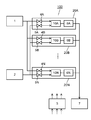
- FIG. 7 shows a conventional fuel cell system 200 described in Patent Document 1.
- the fuel cell system 200 includes first current converters 208A to 208D, second current converters 209A to 209D, and fuel cell units 220A to 220D.
- the fuel cell units 220A to 220D are composed of controllers 203A to 203D, output controllers 206A to 206D, and fuel cell stacks 210A to 210D.
- the controllers 203A to 203D control the power generation outputs of the fuel cell stacks 210A to 210D, and convert the DC power generated by the fuel cell stacks 210A to 210D by the output controllers 206A to 206D into AC power.
- the conventional fuel cell system 200 detects the current flowing through the commercial power line using the first current converters 208A to 208D, and uses the second current converters 209A to 209D to generate the power generation output lines of the fuel cell stacks 210A to 210D.
- the power generation output of the fuel cell stacks 210A to 210D is controlled by monitoring the power of the commercial power line and the power generation outputs of the plurality of fuel cell units 220A to 220D.
- the power generation outputs of the fuel cell stacks 210A to 210D can be controlled to be equal and the power can be output stably.
- the power generation efficiency of the plurality of fuel cell units 220A to 220D as a whole can be increased.
- the fuel cell stack deteriorates and the voltage decreases as the operation time of the fuel cell system increases, so that the power generation efficiency of the fuel cell system as a whole increases.
- the power generation output of each fuel cell unit is controlled to be equal.
- each fuel cell unit When controlling so that the power generation output of each fuel cell unit is equal, for example, when four fuel cell units with a rated power output of 700 W are connected in parallel and the power consumption consumed by the electrical equipment is 1200 W, Each of the four fuel cell units generates 300 W of power. In this case, all four fuel cell units operate, and the voltage of all fuel cell stacks in the fuel cell unit decreases with the operation time.
- the power generation of each fuel cell stack When controlling the output to be uniform, the voltage of all fuel cell stacks decreases, and the upper limit of the capacity of the fuel gas supply system (for example, gas cylinder and booster) that supplies fuel gas to the fuel cell stack Therefore, the necessary fuel gas is not supplied to the fuel cell stack. For this reason, there is a problem that the current of the fuel cell stack cannot be increased and the maximum power generation output decreases with the operation time.
- the fuel gas supply system for example, gas cylinder and booster
- the present invention solves the conventional problems as described above, and provides a fuel cell system in which a maximum power generation output is prevented from decreasing with an operation time in a fuel cell system in which a plurality of fuel cell stacks are connected. .
- a fuel cell system operates a minimum number of fuel cell stacks necessary for obtaining a target power generation output in a fuel cell system in which a plurality of fuel cell stacks are connected.
- a controller for controlling the operation of the plurality of fuel cell stacks is provided.
- the number of fuel cell stacks whose voltage decreases with the operation time can be minimized, and the maximum power generation output decreases with the operation time compared to the case where all the fuel cell stacks are operated with respect to the target power generation output. Can be suppressed.
- FIG. 1 is a block diagram showing the configuration of the fuel cell system according to Embodiment 1 of the present invention.
- FIG. 2 is a flowchart showing a method of operating the fuel cell system according to Embodiment 1 of the present invention.
- FIG. 3 is a block diagram showing the configuration of the fuel cell system according to Embodiment 2 of the present invention.
- FIG. 4 is a flowchart showing a method of operating the fuel cell system according to Embodiment 2 of the present invention.
- FIG. 5 is a flowchart showing an operation method of the fuel cell system according to Embodiment 3 of the present invention.
- FIG. 6 is a flowchart showing a method of operating the fuel cell system according to Embodiment 4 of the present invention.
- FIG. 7 is a block diagram showing a configuration of a conventional fuel cell system.
- FIG. 1 is a block diagram showing the configuration of the fuel cell system according to Embodiment 1 of the present invention.
- a fuel cell system 100 includes a fuel gas supplier 1, an oxidizing gas supplier 2, a controller 3, fuel gas switching valves 4A to 4N, oxidizing gas switching valves 5A to 5N, and an output controller. 6 (output controllers 6A to 6N), an electric device 7, and fuel cell stacks 10A to 10N.
- the fuel gas supply device 1 is a device that supplies fuel gas to the fuel cell stacks 10A to 10N.
- Examples of the fuel gas supply device 1 include a fuel gas infrastructure having a predetermined supply pressure. Hydrogen gas is used as the fuel gas.
- the oxidizing gas supply device 2 is a device that adjusts the flow rate of the oxidizing gas that supplies the oxidizing gas to the fuel cell stacks 10A to 10N.
- a constant displacement pump is used.
- air is used as the oxidizing gas.
- the controller 3 only needs to have a control function, and includes an arithmetic processing unit (not shown) and a storage unit (not shown) for storing a control program.
- An example of the arithmetic processing unit is a CPU.
- a memory is exemplified as the storage unit.
- the fuel gas switching valves 4A to 4N are respectively installed in paths for supplying fuel gas from the fuel gas supply device 1 to the fuel cell stacks 10A to 10N, and are opened and closed according to control signals from the controller 3, respectively.
- the fuel gas switching valves 4A to 4N may be any as long as they can open and close the path, and examples thereof include electromagnetic valves.
- the oxidizing gas switching valves 5A to 5N are respectively installed in paths for supplying the oxidizing gas from the oxidizing gas supply device 2 to the fuel cell stacks 10A to 10N, and are opened and closed according to control signals from the controller 3, respectively.
- the oxidizing gas switching valves 5A to 5N may be any valves that can open and close the path, and for example, electromagnetic valves are used.
- the output controller 6 is provided between the fuel cell stacks 10A to 10N and the electric device 7, and is a DC / AC converter (not shown) for converting DC power generated by the fuel cell stacks 10A to 10N into AC power. )).
- the output controller 6 is composed of an inverter, for example.
- the electric device 7 is a power consuming device such as a refrigerator and a washing machine, for example, and includes various devices that use electricity and may be any device that consumes AC power supplied from the output controller 6.
- the fuel cell stacks 10A to 10N generate power using the fuel gas supplied from the fuel gas supply device 1 and the oxidizing gas supplied from the oxidizing gas supply device 2.
- the fuel cell stack for example, a polymer electrolyte fuel cell is used.
- the configuration of a polymer electrolyte fuel cell generally has a structure in which an MEA (Membrane Electrode Assembly) is sandwiched between separators.
- the MEA generally has a structure in which a gas diffusion layer, a cathode catalyst layer, a solid polymer electrolyte membrane, an anode catalyst layer, and a gas diffusion layer are laminated.
- the cell reaction proceeds in a catalyst layer composed of a catalyst, a carrier supporting the catalyst, and an ionomer (ion conductive polymer).
- the cause of the deterioration is generally the poisoning of the cathode catalyst layer due to the impurity component contained in the atmosphere, and the change in the electrode structure due to the poisoning of the anode catalyst layer due to the impurity component contained in the fuel gas.
- the electrode structure is changed, the gas diffusibility and the discharge of generated water are lowered, and the voltage is lowered.
- This operation time is the time during which each of the fuel cell stacks 10A to 10N is generating power.
- the fuel cell stack 10 indicates one or a plurality of units.
- the fuel gas switching valves 4A to 4N mean that N fuel gas switching valves 4 are provided, and the oxidizing gas switching valves 5A to 5N include N oxidizing gas switching valves 5. It means that.
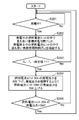
- FIG. 2 is a flowchart showing an operation method of the fuel cell system 100 according to Embodiment 1 of the present invention.
- the operations (steps) shown in the flowchart of FIG. 2 are executed under the control of the controller 3.
- the controller 3 starts the operation of the fuel cell system 100 when the power is supplied to the fuel cell system 100 and always performs the following operations.
- the controller 3 determines the target power generation output generated by the fuel cell system 100 in accordance with the fluctuation of the power consumption consumed by the electric device 7, and checks the fluctuation of the target power generation output (step S101).
- the target power generation output fluctuates from 0 W to 200 W, for example, not only during power generation but also when switching from startup to power generation.
- step S101 If the controller 3 confirms the change in the target power generation output in step S101 (Yes in S101), the process proceeds to step S102.
- step S102 the controller 3 operates the fuel cell stack 10 so that the target power generation output can be obtained with the smallest number of operating fuel cell stacks 10 with respect to the target power generation output confirmed in step S101. Is calculated. That is, the controller 3 calculates the minimum number of fuel cell stacks 10 necessary for obtaining the target power generation output.
- the power generation output of the first fuel cell stack 10 is 700 W.
- the power generation output of the second fuel cell stack 10 is 500 W, and the required minimum number is calculated as two.
- step S101 When the controller 3 confirms that there is no change in the target power generation output in step S101 (No in S101), the process returns to step S101 and step S101 is repeated.
- step S103 the controller 3 compares the number of fuel cell stacks 10 currently generating power with the number of fuel cell stacks 10 calculated in step S102, and changes the number to the number of fuel cell stacks 10 to be operated. If there is any (Yes in S103), the process proceeds to Step S104.
- step S104 the controller 3 confirms whether the number of operating fuel cell stacks 10 confirmed in step S103 increases, and if it increases (Yes in S104), the controller 3 proceeds to step S105.
- step S105 the controller 3 selects the fuel cell stack 10k having a relatively short cumulative power generation time among the fuel cell stacks 10 whose power generation is stopped, and proceeds to step S106.
- the accumulated power generation time is the total time of power generation time generated from the initial state where the fuel cell stack 10 does not generate power.
- step S106 the controller 3 opens the fuel gas switching valve 4k and the oxidizing gas switching valve 5k to start the fuel cell stack 10k selected in step S105, and proceeds to step S107.
- step S107 the controller 3 causes the output controller 6 to start flowing current, and returns to step S101.
- the control cycle from step S101 to step S107 may be set according to the speed of fluctuation of the target power generation output, for example, 1 second.
- step S104 If the number of fuel cell stacks 10 to be operated decreases in step S104 (No in S104), the process proceeds to step S108.
- step S108 the controller 3 selects the fuel cell stack 10m having a relatively long accumulated power generation time among the fuel cell stacks 10 that are generating power, and proceeds to step S109.
- step S109 the controller 3 closes the fuel gas switching valve 4m and the oxidizing gas switching valve 5m to stop the fuel cell stack 10m selected in step S108, and proceeds to step S110.
- step S110 the controller 3 stops the current flow by the output controller 6, and returns to step S101.
- the control cycle from step S101 to step S110 may be set according to the speed of fluctuation of the target power generation output, and is set to 1 second, for example.
- step S101 to step S110 described above are repeated in the fuel cell system 100.
- the fuel cell system 100 can minimize the number of fuel cell stacks 10 whose voltage decreases with the operation time, and all the fuel cells with respect to the target power generation output. Compared with the case where the stack 10 is operated, it is possible to suppress the maximum power generation output from decreasing with the operation time.
- a specific fuel is selected by operating with priority from the fuel cell stack 10 whose accumulated power generation time is relatively short among the fuel cell stacks 10 whose power generation is stopped. Only the battery stack 10 can be prevented from undergoing an extreme voltage drop.
- a specific fuel is stopped by preferentially stopping power generation from the fuel cell stack 10 having a relatively long accumulated power generation time among the fuel cell stacks 10 that are generating power. Only the battery stack 10 can be prevented from undergoing an extreme voltage drop.
- the fuel gas supply device 1 is not limited to the fuel gas infrastructure, and may be a device configured by a fuel gas cylinder or a booster and a flow meter to adjust the flow rate of the fuel gas.
- the fuel gas is not limited to hydrogen gas, and hydrocarbons such as city gas and alcohols such as methanol may be used.
- the reforming unit that generates hydrogen gas by the reforming reaction using the fuel gas is switched between the fuel gas supply 1 and the fuel gas. It may be provided between the valves 4A to 4N.
- the oxidizing gas supply device 2 is not limited to a constant displacement pump, and may be composed of a booster and a flow meter.
- controller 3 may be composed of a single controller that performs centralized control, or may be composed of a plurality of controllers that perform distributed control in cooperation with each other.
- only one output controller 6 may be provided for the plurality of fuel cell stacks 10A to 10N, or for each of the plurality of fuel cell stacks 10A to 10N. Also good. In general, it is more efficient to convert DC power into AC power when the output controllers 6A to 6N are provided for the plurality of fuel cell stacks 10A to 10N, respectively.
- the fuel cell stacks 10A to 10N are not limited to solid polymer fuel cells, and may be any other type, for example, solid oxide fuel cells and phosphoric acid fuel cells.
- the reformer and the fuel cell stacks 10A to 10N are built in one container.
- the operation time is not limited to the time during which each of the fuel cell stacks 10A to 10N is generating power, but the time during which the oxidizing gas is supplied to the fuel cell stacks 10A to 10N and the fuel gas to the fuel cell stacks 10A to 10N. It may be the time being supplied.
- the controller 3 starts the operation of the fuel cell system 100 when the power is supplied to the fuel cell system 100.
- the present invention is not limited to this, and the fuel cell stack 10 generates power.
- the start time may be the start.
- the fuel cell stacks 10A to 10N are connected in parallel, but the present invention is not limited to this, and may be connected in series.
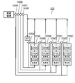
- FIG. 3 is a block diagram showing the configuration of the fuel cell system according to Embodiment 2 of the present invention.
- the same components as those in the first embodiment are denoted by the same reference numerals, and the description thereof is omitted in the present embodiment.
- the fuel cell stack 10 of the present embodiment shown in FIG. 3 the fuel cell stack 10, the fuel gas switching valve 4, the oxidizing gas switching valve 5, the output controller 6, and the fuel cell unit controller are respectively provided.
- This embodiment is different from the first embodiment in that a plurality of fuel cell units 20 provided one by one (fuel cell units 20A to 20N) are connected.
- the fuel cell units 20A to 20N include fuel cell stacks 10A to 10N that generate DC power, output controllers 6A to 6N that convert DC power from the fuel cell stacks 10A to 10N into AC power, and fuel cell stacks 10A to 10N.
- a fuel cell unit controller for controlling the operation of 10N is provided.
- Each of the fuel cell units 20A to 20N receives a command from the controller 3 and starts and stops.
- the output controllers 6A to 6N are provided for the plurality of fuel cell stacks 10A to 10N, respectively, because the efficiency of converting DC power into AC power is better. Loss can be reduced.
- the fuel cell unit 20 indicates one or a plurality of units. Further, in order to distinguish each of the arbitrary fuel cell units 20, a suffix is added to the fuel cell unit 20 as “k” or “m”. “K” and “m” mean arbitrary integers of 1 to n.
- the fuel gas switching valves 4A to 4N mean that N fuel gas switching valves 4 are provided, and the oxidizing gas switching valves 5A to 5N include N oxidizing gas switching valves 5. It means that. Further, the output controllers 6A to 6N mean that N output controllers 6 are provided, and the fuel cell stacks 10A to 10N mean that N fuel cells 10 are provided. .
- each device constituting the fuel cell system 100 in the present embodiment is the same as that in the first embodiment, the same components as those in the first embodiment are denoted by the same reference numerals and description thereof is omitted.
- the difference between the fuel cell system 100 of the present embodiment and the first embodiment is that the controller 3 generates the accumulated power generation time of the fuel cell unit 20 with the longest accumulated power generation time during power generation, and the accumulated power generation time while power generation is stopped.
- the controller 3 When the difference from the accumulated power generation time of the shortest fuel cell unit 20 is equal to or greater than a predetermined value, the fuel cell unit 20 having the longest cumulative power generation time during power generation is stopped and the power generation time is shortest while power generation is stopped. This is to control the fuel cell unit 20 to generate power and maintain the power generation output.
- FIG. 4 is a flowchart showing an operation method of the fuel cell system 100 of the present embodiment.
- the operation (step) shown in the flowchart of FIG. 4 is executed under the control of the controller 3.
- the controller 3 starts the operation of the fuel cell system 100 when the power is supplied to the fuel cell system 100 and always performs the following operations.
- the controller 3 confirms whether at least one of the fuel cell units 20A to 20N is generating power (step S201).
- step S201 When the controller 3 confirms in step S201 that at least one of the fuel cell units 20A to 20N is generating power (Yes in S201), the process proceeds to step S202.
- Step S201 When the controller 3 confirms that the fuel cell units 20A to 20N are not generating power in Step S201 (Yes in S201), the process returns to Step S201.
- step S202 the controller 3 calculates the longest cumulative power generation time (Tk) among the fuel cell units 20 that are generating power and the shortest cumulative power generation time (Tm) among the fuel cell units 20 that are not generating power. Confirm and go to step S203.
- step S203 the controller 3 sets the longest cumulative power generation time (Tk) among the fuel cell units 20 that are generating power and the shortest cumulative power generation time (Tm) among the fuel cell units 20 that are not generating power. It is confirmed whether or not the difference (Tk ⁇ Tm) is equal to or greater than a predetermined value T1, and when the accumulated power generation time difference (Tk ⁇ Tm) is equal to or greater than the predetermined value T1, the process proceeds to step S204.
- Tk longest cumulative power generation time
- Tm shortest cumulative power generation time
- the continuous power generation time of the fuel cell unit 20 from the start of power generation to the stop of power generation is generally 24 hours when the fuel cell stack 10 is a polymer electrolyte fuel cell, but the solid oxide fuel In the case of a battery, it may be 1000 hours or more.
- the appropriate predetermined value T1 differs depending on the type of the fuel cell stack 10 used and the operation method of the fuel cell system 100. Therefore, depending on the type of the fuel cell stack 10 used, the operation method of the fuel cell system 100, etc.
- step S201 When the controller 3 confirms that the difference in accumulated power generation time (Tk ⁇ Tm) is less than the predetermined value T1 in step S203 (No in S201), the process returns to step S201.
- the control cycle from step S201 to step S203 is, for example, 1 second.
- step S204 the controller 3 lowers the power generation output of the fuel cell unit 20k having the longest accumulated power generation time (Tk) among the fuel cell units 20 that are generating power by 5 W, and is the highest among the fuel cell units 20 that are generating power.
- the fuel cell with the shortest cumulative power generation time (Tm) among the fuel cell units 20 in which power generation is stopped so that the same power generation output as before the power generation output of the fuel cell unit 20k with a long cumulative power generation time (Tk) is lowered can be obtained.
- the unit 20m is caused to generate power, the power generation output is increased by 5 W, and the process proceeds to step S205.
- the fuel cell unit controller When generating power in the fuel cell unit 20m, the fuel cell unit controller opens the fuel gas switching valve 4m and the oxidizing gas switching valve 5m, and starts flowing current through the output controller 6m.
- the minimum power generation output of the fuel cell unit 20m having the shortest cumulative power generation time (Tm) among the fuel cell units 20 in which power generation is stopped is 200 W, for example, the power generation starts from 200 W, and the power generation of the fuel cell system 100 is started. The output exceeds the target power generation output.
- the controller 3 After the power generation output of the fuel cell unit 20k having the longest accumulated power generation time (Tk) among the fuel cell units 20 that are generating power has decreased by 200 W, the controller 3 The power generation output of the fuel cell unit 20m having the shortest cumulative power generation time (Tm) is increased by 200W. At this time, since the power generation output is temporarily reduced by 200 W, power may be supplied from a commercial power source or the like.
- step S205 the controller 3 confirms whether the power generation output of the fuel cell unit 20k having the longest accumulated power generation time (Tk) among the fuel cell units 20 that are generating power is 0W. If yes, the process returns to step S201.
- step S205 When the controller 3 confirms in step S205 that the power generation output of the fuel cell unit 20k having the longest accumulated power generation time (Tk) among the fuel cell units 20 that are generating power is not 0 W (No in S205) Returns to step S204.
- control cycle from step S204 to step S205 may be set to a value that allows the fuel cell unit 20 to sufficiently cope with the increase / decrease amount of the power generation output, for example, 1 second.
- the fuel cell system 100 can prevent only a specific fuel cell unit 20 from undergoing an extreme voltage drop regardless of the increase or decrease in the number of operating fuel cell units 20. .
- the fuel cell system 100 includes the fuel cell unit 20 with the longest cumulative power generation time during power generation, and the fuel cell unit 20 with the shortest cumulative power generation time while power generation is stopped. Is switched, the same power generation output as that before switching can be maintained, and a stable power generation output can be supplied.
- the controller 3 starts the operation of the fuel cell system 100 when the power is supplied to the fuel cell system 100.
- the controller 3 is not limited to this, and starts when the fuel cell stacks 10A to 10N start power generation. It is good.
- control cycle from step S201 to step S203 is 1 second
- the present invention is not limited to this, and it is configured to check whether the difference in accumulated power generation time (Tk ⁇ Tm) is equal to or greater than a predetermined value T1 once every hour. It is good.
- step S204 the increase / decrease in the power generation output is set to 5 W, but the present invention is not limited to this, and the fuel cell unit 20 may be set to a value that can sufficiently cope with the increase / decrease in the power generation output.
- the fuel cell unit 20k having the longest cumulative power generation time (Tk) among the fuel cell units 20 during power generation and the fuel cell unit having the shortest cumulative power generation time (Tm) among the fuel cell units 20 during power generation stop When switching to 20 m, the number of fuel cell units 20 that are generating power transiently increases, but this is assumed to be temporary.
- step S204 after the power generation output of the fuel cell unit 20m having the shortest cumulative power generation time (Tm) among the fuel cell units 20 in which power generation is stopped is increased to, for example, 200 W of the minimum power generation output,
- the power generation output of the fuel cell unit 20k having the longest accumulated power generation time (Tk) among the battery units 20 may be reduced by 200W.
- the power generation output temporarily increases by 200W, in this case, the fuel cell system 100 Inside, the increased power generation output 200W is consumed by, for example, a heater.
- the fuel cell system 100 is an example of the fuel cell system 100 to which a plurality of fuel cell units 20A to 20N are connected.
- the present invention is not limited to this, and a plurality of fuel cell stacks 10A to 10N are included. It may be a connected fuel cell system.
- the fuel cell system 100 according to the third embodiment of the present invention is different from the first and second embodiments in that the controller 3 is stopping power generation when increasing the number of operating fuel cell stacks 10A to 10N.
- the controller 3 is stopping power generation when increasing the number of operating fuel cell stacks 10A to 10N.
- the fuel cell stacks 10A to 10N that have a relatively high voltage at the time of the previous power generation are preferentially operated, and the number of operation of the fuel cell stacks 10A to 10N is reduced.
- the fuel cell stacks 10A to 10N have a relatively low voltage, and the power generation is stopped preferentially from the fuel cell stacks 10A to 10N having a relatively low voltage.
- the fuel cell system 100 includes a detection unit that detects voltages at both ends of the fuel cell stacks 10A to 10N during power generation, and a memory that stores voltage histories of voltages at both ends of the fuel cell stacks 10A to 10N. A part.
- FIG. 5 is a flowchart showing an operation method of the fuel cell system 100 of the present embodiment. The operations (steps) shown in the flowchart of FIG. 5 are executed under the control of the controller 3.
- the controller 3 starts the operation of the fuel cell system 100 when the power is supplied to the fuel cell system 100, and always performs the following operations.
- the controller 3 determines the target power generation output generated by the fuel cell system 100 in accordance with the fluctuation of the power consumption consumed by the electric device 7, and checks the fluctuation of the target power generation output (step S301).
- the target power generation output fluctuates from 0 W to 200 W, for example, not only during power generation but also when switching from startup to power generation.
- step S301 If the controller 3 confirms a change in the target power generation output in step S301 (Yes in S301), the process proceeds to step S302.
- step S302 the controller 3 determines the number of fuel cell stacks 10 to be operated so that the target power generation output can be obtained with as few fuel cell stacks 10 as possible with respect to the target power generation output confirmed in step S301. calculate. That is, the minimum number of fuel cell stacks 10 necessary for obtaining the target power generation output is calculated.
- the power generation of the first fuel cell stack 10 is performed. Assuming that the output is 700 W and the power generation output of the second fuel cell stack 10 is 500 W, the number of fuel cell stacks 10 (necessary minimum number) that need to be operated to obtain the target power generation output is calculated as two.
- step S301 When the controller 3 confirms that the target power generation output does not fluctuate in step S301 (No in S301), the process returns to step S301.
- step S303 the controller 3 compares the number of fuel cell stacks 10 currently generating power with the number of fuel cell stacks 10 calculated in step S302, and if the number has changed (Yes in S303). ) Proceeds to step S304.
- step S304 the controller 3 confirms whether the number of the fuel cell stacks 10 confirmed in step S303 increases, and if it increases (Yes in S304), the controller 3 proceeds to step S305.
- step S305 the controller 3 refers to the voltage history in the storage unit, and selects the fuel cell stack 10k having a relatively high voltage at the previous power generation from the fuel cell stacks 10 that have stopped generating power, and then step S306. Proceed to
- an average value of the voltage at the previous power generation may be used, or an instantaneous value before stopping may be used. Since the low power generation output (for example, 200 W) is higher than the high power generation output (for example, 700 W), it is preferable to compare the voltages at the same power generation output when comparing the voltages at the previous power generation.
- the fuel cell stack 10k having a relatively high voltage at the time of the previous power generation is an average value of the voltage at the time of the previous power generation (an average value of the voltage is a voltage per predetermined time (for example, several seconds to several tens of seconds)).
- the fuel cell stack 10 whose average value is higher than that of the other fuel cell stack 10, the fuel cell stack 10 whose voltage value at a certain moment before stopping the power generation is higher than that of the other fuel cell stack 10, and the power generation at the previous power generation When comparing the voltages of the fuel cell stacks 10 having the same power generation output (for example, 200 W), the fuel cell stack 10 having an average voltage higher than that of the other fuel cell stacks 10 and the power generation output at the previous power generation are the same. When the voltages of the fuel cell stacks 10 of the power generation output (for example, 200 W) are compared, the fuel cell stack 1 with the higher voltage value at a certain moment before stopping the power generation It means, and the like.
- step S306 the controller 3 opens the fuel gas switching valve 4k and the oxidizing gas switching valve 5k to start the fuel cell stack 10k selected in step S305, and proceeds to step S307.
- step S307 the controller 3 causes the output controller 6 to start flowing current, and returns to step S301.
- the control cycle from step S301 to step S307 may be set according to the speed of fluctuation of the target power generation output, for example, 1 second.
- step S304 If the number of fuel cell stacks 10 decreases in step S304 (No in S304), the process proceeds to step S308.
- step S308 the controller 3 refers to the voltage detected by the detection unit, selects the fuel cell stack 10m having a relatively low voltage among the fuel cell stacks 10 that are generating power, and then proceeds to step S309.
- an average value of the voltage during power generation may be used, or an instantaneous value of the voltage during power generation may be used.
- the voltage depends on the magnitude of the power generation output.
- the low power generation output for example, 200 W
- the high power generation output for example, 700 W
- the detected fuel cell stack 10m having a relatively low voltage is, for example, a fuel cell stack 10 in which the average value of voltages during power generation is lower than that of other fuel cell stacks 10 during power generation, Of the fuel cell stack 10 having a value lower than that of the other fuel cell stack 10 that is generating power and the fuel cell stack 10 having the same power generation output (for example, 200 W) during power generation, the average value of the voltage during power generation is the other fuel that is generating power.
- step S309 the controller 3 closes the fuel gas switching valve 4m and the oxidizing gas switching valve 5m to stop the fuel cell stack 10m selected in step S308, and proceeds to step S310.
- step S310 the controller 3 stops the current flow by the output controller 6, and returns to step S301.
- the control cycle from step S301 to step S310 may be set according to the speed of fluctuation of the target power generation output, for example, 1 second.
- step S301 to step S310 are repeated.
- the fuel cell system 100 can minimize the number of fuel cell stacks 10 whose voltage decreases with the operation time, and all the fuel cell stacks 10 with respect to the target power generation output. Compared with the case where it operates, it can suppress that a maximum electric power generation output falls with an operating time.
- the fuel cell stack having a relatively high voltage during the previous power generation among the fuel cell stacks 10 in which power generation is stopped since the fuel cell stack 10 to be operated is selected based on the voltage at the time of the previous power generation, not the cumulative power generation time, the fuel cell stack with a small voltage drop is more surely configured. Can generate electricity.
- the number of operating fuel cell stacks 10 is reduced, it is configured to stop power generation preferentially from the fuel cell stack 10 having a relatively low voltage among the fuel cell stacks 10 that are generating power.
- the fuel cell stack 10 with a large voltage drop can be surely stopped.
- the controller 3 detects the voltages at both ends of each of the fuel cell stacks 10A to 10N and refers to the voltage at the previous power generation from the storage unit.
- the present invention is not limited to this.
- the single cell voltage of each of the stacks 10A to 10N may be detected and the single cell voltage at the previous power generation may be referred to.
- the controller 3 starts the operation of the fuel cell system 100 when the power is supplied to the fuel cell system 100.
- the controller 3 is not limited to this, and starts when the fuel cell stacks 10A to 10N start power generation. It is good.
- the fuel cell system 100 in the present embodiment is an example of the fuel cell system 100 to which a plurality of fuel cell stacks 10A to 10N are connected.
- the present invention is not limited to this, and the fuel cell stacks 10A to 10N and output control are not limited thereto.
- a fuel cell system in which a plurality of fuel cell units 20A to 20N including the devices 6A to 6N are connected may be used.
- the fuel cell system 100 according to the fourth embodiment of the present invention is different from the first to third embodiments in that the controller 3 determines the voltage of the fuel cell stacks 10A to 10N having the lowest voltage during power generation, When the difference between the voltage at the previous power generation of the fuel cell stacks 10A to 10N having the highest voltage during the previous power generation is stopped and exceeds a predetermined value, the fuel cell stacks 10A to 10N having the lowest voltage during the power generation are stopped. In addition, the fuel cell stacks 10A to 10N having the highest voltage at the time of the previous power generation during power generation stop are generated to maintain the power generation output.
- the controller 3 includes a detection unit that detects voltages at both ends of the fuel cell stacks 10A to 10N that are generating power, and a voltage at both ends of the fuel cell stacks 10A to 10N.
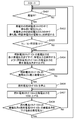
- FIG. 6 is a flowchart showing an operation method of the fuel cell system 100 according to Embodiment 4 of the present invention.
- the operation (step) shown in the flowchart of FIG. 6 is executed under the control of the controller 3.
- the controller 3 starts the operation of the fuel cell system 100 when the power is supplied to the fuel cell system 100, and always performs the following operations.
- the controller 3 confirms whether or not the fuel cell stack 10 is generating power (step S401).
- step S401 When the controller 3 confirms in step S401 that the fuel cell stack 10 is generating power (Yes in S401), the process proceeds to step S402.
- step S401 when the fuel cell stack 10 is not generating power (Yes in S401), the process returns to step S401, and step S401 is repeated.
- step S402 the controller 3 obtains the lowest voltage (Vk) in the fuel cell stack 10 that is generating power and the highest voltage (Vm) during the previous power generation in the fuel cell stack 10 that is not generating power. Confirm and go to step S403.
- step S403 the controller 3 determines the difference between the lowest voltage (Vk) in the fuel cell stack 10 during power generation and the highest voltage (Vm) during the previous power generation in the fuel cell stack 10 during power generation stop. Whether or not (Vm ⁇ Vk) is equal to or greater than the predetermined value V1 is checked. If the voltage difference (Vm ⁇ Vk) is equal to or greater than the predetermined value V1, the process proceeds to step S404.
- the voltage differs depending on the magnitude of the power generation output, and the low power generation output (for example, 200 W) is higher than the high power generation output (for example, 700 W). Therefore, when calculating the voltage difference (Vm ⁇ Vk) It is preferable to compare the voltages at the same power generation output.
- step S403 the controller 3 detects the lowest voltage (Vk) in the fuel cell stack 10 that is generating power with the power generation output 200W, and the previous power generation in the fuel cell stack 10 that is not generating power.
- a difference (Vm ⁇ Vk) from the voltage (Vm) of the fuel cell stack 10 having a power generation output of 200 W is calculated.
- step S403 if the voltage difference (Vm ⁇ Vk) is less than the predetermined value V1 (No in S201), the process returns to S401.
- the control period from step S401 to step S403 is, for example, 1 second.
- step S404 the controller 3 uses the power generation output of the fuel cell stack 10k having the lowest voltage (Vk) among the fuel cell stacks 10 that are generating power as the minimum power generation output (for example, 200 W) that can be generated by the fuel cell stack 10k.
- the fuel cell stack 10m having the highest voltage (Vm) at the time of the previous power generation among the fuel cell stacks 10 whose power generation is stopped is generated up to 200 W, and the process proceeds to step S405.
- the controller 3 When generating electricity in the fuel cell stack 10m, the controller 3 opens the combustion gas switching valve 4m and the oxidizing gas switching valve 5m, and starts the flow of current through the output controller 6.
- step S405 the controller 3 confirms whether the power generation output of the fuel cell stack 10k has decreased to 200 W, which is the minimum power generation output that can be generated by the fuel cell stack 10k, and the power generation output of the fuel cell stack 10k is 200 W. If it has decreased (Yes in S405), the process proceeds to step S406.
- step S405 when the controller 3 confirms that the power generation output of the fuel cell stack 10k has not decreased to 200 W, which is the minimum power generation output that can be generated by the fuel cell stack 10k (No in S405), The process returns to step S404.
- step S406 the controller 3 stops the fuel cell stack 10k, and proceeds to step S407.
- the fuel gas switching valve 4k and the oxidizing gas switching valve 5k are closed, and the flow of current is stopped by the output controller 6.
- step S407 the controller 3 reduces the power generation output of the fuel cell stack 10k by the power generation output of the fuel cell stack 10m having the highest previous power generation voltage (Vm) among the fuel cell stacks 10 whose power generation is stopped.
- Vm previous power generation voltage
- the power generation output is increased by 10 W, for example, and the process proceeds to step S405.
- step S408 the controller 3 confirms whether the power generation output of the fuel cell stack 10m is the same as the power generation output before the power generation output of the fuel cell stack 10k is lowered. If the power generation output is the same (Yes in S408), step S408 is performed. Return to S401.
- step S409 When the controller 3 confirms in step S409 that the power generation output of the fuel cell stack 10m is not the same as the power generation output before the power generation output of the fuel cell stack 10k is lowered (No in S408), step S407 is performed. Return to.
- control cycle from step S407 to step S408 may be set to a value that allows the fuel cell stack 10 to sufficiently cope with the increase / decrease amount of the power generation output, for example, 1 second.
- the fuel cell system 100 can prevent the voltage of only a specific fuel cell stack 10 from being extremely lowered regardless of the increase or decrease in the number of operating fuel cell stacks 10. . Further, when switching between the fuel cell stack 10 having the lowest voltage among the fuel cell stacks 10 that are generating power and the fuel cell stack 10 having the highest voltage during the previous power generation among the fuel cell stacks 10 that are not generating power. The same power generation output as before switching can be maintained, and a stable power generation output can be supplied.
- each of the fuel cell stacks 10A to 10N the voltages at both ends of each of the fuel cell stacks 10A to 10N are detected and the voltage at the previous power generation is referred from the storage unit.
- the present invention is not limited to this, and each of the fuel cell stacks 10A to 10N is referred to. May be detected and the single cell voltage at the previous power generation may be referred to.
- step S403 the voltage difference (Vm ⁇ Vk) is a predetermined value V1 or more.
- the fuel cell stack 10k having the lowest voltage (Vk) among the fuel cell stacks 10 during power generation and the fuel cell stack having the highest voltage (Vm) at the previous power generation time among the fuel cell stacks 10 during power generation stop When switching 10 m, the number of fuel cell stacks 10 that are generating power transiently increases, but this is assumed to be temporary.
- the controller 3 starts the operation of the fuel cell system 100 when, for example, power is supplied to the fuel cell system 100.
- the controller 3 is not limited to this, and when the fuel cell stacks 10A to 10N start power generation. You can also start.
- control cycle from step S401 to step S403 is, for example, 1 second, but is not limited to this, and it is confirmed once every hour whether the voltage difference (Vm ⁇ Vk) is equal to or greater than the predetermined value V1. Good.
- step S408 the controller 3 confirms whether the power generation output of the fuel cell stack 10m is the same as the power generation output before the power generation output of the fuel cell stack 10k is lowered.
- the device 3 may determine the power generation output of the fuel cell stack 10m in accordance with the current target power generation output.
- step S405 the amount of increase in the power generation output is set to 10 W.
- the present invention is not limited to this, and the fuel cell stack 10 may be set to a value that can sufficiently cope with the increase or decrease in the power generation output.
- the fuel cell system 100 temporarily reduces the power generation output of the fuel cell system 100 while the power generation output of the fuel cell stack 10k is being lowered. It is also possible to supply power from such as.
- the fuel cell stack 10m having the highest voltage (Vm) at the time of the previous power generation among the fuel cell stacks 10 whose power generation is stopped is generated, and the power generation output is increased to the minimum power generation output (for example, 200 W).
- the power generation output of the fuel cell stack 10k having the lowest voltage (Vk) among the fuel cell stacks 10 may be reduced by 200 W.
- the power generation output temporarily increases by 200 W, in this case, the inside of the fuel cell system 100
- the increased power generation output 200W is consumed by a heater or the like.
- the fuel cell system 100 in the present embodiment is an example of the fuel cell system 100 to which a plurality of fuel cell stacks 10A to 10N are connected.
- the present invention is not limited to this, and the fuel cell stacks 10A to 10N and output control are not limited thereto.
- a fuel cell system in which a plurality of fuel cell units 20A to 20N including the devices 6A to 6N are connected may be used.
- the present invention has been illustrated and described in the first to fourth embodiments. However, the present invention is independent of each other from the embodiments illustrated in the first to fourth embodiments.
- the present invention is not limited to such a configuration, and includes a configuration in which the embodiments illustrated in the first to fourth embodiments are combined.
- the fuel cell system 100 can determine the number of operating fuel cell stacks by combining the controls exemplified in the first and third embodiments. In this case, for example, based on the control based on the accumulated power generation time as exemplified in the first embodiment and the control based on the voltage at the previous power generation as exemplified in the third embodiment, the fuel cell is calculated from the respective weights. It may be configured to be able to determine the number of operating stacks.
- the fuel cell system is a fuel cell system in which a plurality of fuel cell stacks are connected, and a plurality of fuel cells that are operated to obtain a target power generation output.
- a controller for operating the fuel cell stack is provided to minimize the number of stacks.
- the number of fuel cell stacks whose voltage decreases with the operation time can be minimized, and the maximum power generation output with the operation time can be obtained as compared with the case where all the fuel cell stacks are operated to obtain the target power generation output. Can be suppressed.
- the controller when the controller increases the number of fuel cell stacks to be operated, the accumulated power generation time is relatively within the fuel cell stack in which power generation is stopped. You may be comprised so that it may operate preferentially from a short fuel cell stack. With such a configuration, it is possible to prevent only a specific fuel cell stack from undergoing an extreme voltage drop.
- the controller when the controller reduces the number of fuel cell stacks to be operated, the cumulative power generation time is relatively long among the fuel cell stacks that are generating power.
- the fuel cell stack may be configured to stop power generation with priority. With such a configuration, it is possible to prevent only a specific fuel cell stack from undergoing an extreme voltage drop.
- the controller has a predetermined difference between the accumulated power generation time of the fuel cell stack during power generation and the cumulative power generation time of the fuel cell stack during power generation stoppage.
- the fuel cell stack that is not generating power may be configured to generate power, and the fuel cell stack that is generating power may be stopped.
- the controller is configured such that the difference between the cumulative power generation time of the fuel cell stack during power generation and the cumulative power generation time of the fuel cell stack during power generation stop is a predetermined value. Even when the fuel cell stack having the longest cumulative power generation time is stopped during power generation, the fuel cell stack having the shortest cumulative power generation time is generated while power generation is stopped, and the power generation output is maintained. Good. With such a configuration, when switching between the fuel cell stack with the longest cumulative power generation time during power generation and the fuel cell stack with the shortest cumulative power generation time while power generation is stopped, the same power generation output as before switching may be maintained. And stable power generation output can be supplied.
- the controller compares the voltage at the previous power generation relative to the fuel cell stack in which power generation is stopped.
- the fuel cell stack may be preferentially operated from a high fuel cell stack.
- the controller when the number of fuel cell stacks to be operated is reduced, the controller has a fuel cell having a relatively low voltage in the fuel cell stack that is generating power.
- the power generation may be stopped preferentially from the stack. With such a configuration, the fuel cell stack with a large voltage drop can be stopped more reliably.
- the fuel cell system includes a fuel cell stack in which the controller has the lowest voltage of the fuel cell stack during power generation and the highest voltage during the previous power generation while power generation is stopped.
- the controller has the lowest voltage of the fuel cell stack during power generation and the highest voltage during the previous power generation while power generation is stopped.
- the difference from the previous power generation voltage is greater than or equal to a predetermined value
- the fuel cell stack with the highest voltage during the previous power generation is stopped during power generation, and the fuel cell stack with the lowest voltage during power generation is stopped. It may be configured as follows. With such a configuration, it is possible to prevent the voltage of only a specific fuel cell stack from being extremely lowered regardless of the increase or decrease in the number of operating fuel cell stacks.
- the fuel cell system includes a fuel cell stack in which the controller has the lowest voltage of the fuel cell stack during power generation and the highest voltage during the previous power generation while power generation is stopped.
- the controller has the lowest voltage of the fuel cell stack during power generation and the highest voltage during the previous power generation while power generation is stopped.
- the difference from the previous power generation voltage is equal to or greater than the specified value
- the fuel cell stack with the lowest voltage during power generation is stopped and the fuel cell stack with the highest voltage during the previous power generation is generated while power generation is stopped.
- the power generation output may be maintained.
- An operation method of a fuel cell system is an operation method of a fuel cell system in which a plurality of fuel cell stacks are connected, and the minimum number of fuels necessary for obtaining a target power generation output There is an operation (step) for operating the battery stack.
- the present invention can minimize the number of fuel cell stacks in which the voltage decreases with the operation time.
- a fuel cell system capable of suppressing a decrease in the maximum power generation output with the operation time as compared with a case where a battery stack is operated. Therefore, it can be widely used in various fuel cell systems for home use and business use.
Abstract
In a fuel cell system (100) according to the present invention, a plurality of fuel cell stacks (10A-10N) is connected, the fuel cell system (100) comprising a control unit (3), wherein the control unit (3) controls the operation of the plurality of fuel stacks (10A-10N) so as to operate a minimally required number of the fuel cell stacks (10A-10N) to obtain a target power generation output.
Description
本発明は、燃料電池スタックを複数、接続した燃料電池システム及びその運転方法に関する。
The present invention relates to a fuel cell system in which a plurality of fuel cell stacks are connected and an operation method thereof.
近年、一戸建て住宅および集合住宅などに設置して使用する家庭用燃料電池システムが知られている。家庭用燃料電池システムは、家庭で消費する消費電力をまかなうように構成され、その発電出力は例えば700~1000Wと小さい。
In recent years, home fuel cell systems that are installed and used in detached houses and apartment houses are known. The household fuel cell system is configured to cover power consumption consumed at home, and its power generation output is as small as 700 to 1000 W, for example.
そこで、このような家庭用燃料電池システムを利用して、例えば、3~5kWの発電出力を得るような技術の開発も進められ、複数の燃料電池ユニットを並列に接続して発電出力を得る制御方法が提案されている(例えば、特許文献1参照)。
Therefore, the development of technology that obtains a power generation output of 3 to 5 kW, for example, using such a household fuel cell system is underway, and a control for obtaining a power generation output by connecting a plurality of fuel cell units in parallel. A method has been proposed (see, for example, Patent Document 1).
図7は、特許文献1に記載された従来の燃料電池システム200を示す。図7に示すように、燃料電池システム200は、第1電流変換器208A~208D、第2電流変換器209A~209Dおよび燃料電池ユニット220A~220Dから構成されている。燃料電池ユニット220A~220Dは、制御器203A~203D、出力制御器206A~206Dおよび燃料電池スタック210A~210Dから構成されている。制御器203A~203Dは、燃料電池スタック210A~210Dの発電出力を制御し、出力制御器206A~206Dにより燃料電池スタック210A~210Dで発電した直流電力を交流電力に変換している。
FIG. 7 shows a conventional fuel cell system 200 described in Patent Document 1. As shown in FIG. 7, the fuel cell system 200 includes first current converters 208A to 208D, second current converters 209A to 209D, and fuel cell units 220A to 220D. The fuel cell units 220A to 220D are composed of controllers 203A to 203D, output controllers 206A to 206D, and fuel cell stacks 210A to 210D. The controllers 203A to 203D control the power generation outputs of the fuel cell stacks 210A to 210D, and convert the DC power generated by the fuel cell stacks 210A to 210D by the output controllers 206A to 206D into AC power.
従来の燃料電池システム200は、第1電流変換器208A~208Dを用いて商業電力ラインを流れる電流を検知し、第2電流変換器209A~209Dを用いて燃料電池スタック210A~210Dの発電出力ラインを流れる電流を検知するよう構成されており、商用電力ラインの電力および複数の燃料電池ユニット220A~220Dの発電出力を監視して、燃料電池スタック210A~210Dの発電出力を制御している。
The conventional fuel cell system 200 detects the current flowing through the commercial power line using the first current converters 208A to 208D, and uses the second current converters 209A to 209D to generate the power generation output lines of the fuel cell stacks 210A to 210D. The power generation output of the fuel cell stacks 210A to 210D is controlled by monitoring the power of the commercial power line and the power generation outputs of the plurality of fuel cell units 220A to 220D.
これにより、燃料電池スタック210A~210Dそれぞれの発電出力が均等になるように制御されるとともに安定して電力を出力することができる。その結果、複数の燃料電池ユニット220A~220D全体の発電効率を高めることができる。
Thereby, the power generation outputs of the fuel cell stacks 210A to 210D can be controlled to be equal and the power can be output stably. As a result, the power generation efficiency of the plurality of fuel cell units 220A to 220D as a whole can be increased.
しかしながら、上記のような従来の構成では、燃料電池システムの運転時間が長くなるほど燃料電池スタックが劣化し、電圧が低下することが考慮されておらず、燃料電池システム全体として発電効率が高くなるように、各々の燃料電池ユニットの発電出力が均等になるように制御されている。
However, in the conventional configuration as described above, it is not considered that the fuel cell stack deteriorates and the voltage decreases as the operation time of the fuel cell system increases, so that the power generation efficiency of the fuel cell system as a whole increases. In addition, the power generation output of each fuel cell unit is controlled to be equal.
各々の燃料電池ユニットの発電出力が均等になるように制御する場合、例えば、定格発電出力700Wの燃料電池ユニットを4台並列に接続し、電気機器が消費する消費電力が1200Wの場合においては、4台の燃料電池ユニットは各々300Wずつ発電する。この場合、4台全ての燃料電池ユニットが稼動することになり、燃料電池ユニット内の全ての燃料電池スタックが運転時間とともに電圧低下する。
When controlling so that the power generation output of each fuel cell unit is equal, for example, when four fuel cell units with a rated power output of 700 W are connected in parallel and the power consumption consumed by the electrical equipment is 1200 W, Each of the four fuel cell units generates 300 W of power. In this case, all four fuel cell units operate, and the voltage of all fuel cell stacks in the fuel cell unit decreases with the operation time.
そのため、1つ目の燃料電池スタックが700W、2つ目の燃料電池スタックが500W、および、3つ目と4つ目の燃料電池スタックは稼動しない場合などに比べ、各々の燃料電池スタックの発電出力が均等になるように制御する場合には、全ての燃料電池スタックの電圧が低下し、燃料電池スタックに燃料ガスを供給する燃料ガス供給系(例えば、ガスボンベおよび昇圧器など)の能力の上限から、必要な燃料ガスが燃料電池スタックに供給されない。このため、燃料電池スタックの電流を上げられず、運転時間ともに最大発電出力が低下するという問題を有している。
Therefore, compared with the case where the first fuel cell stack is 700 W, the second fuel cell stack is 500 W, and the third and fourth fuel cell stacks do not operate, the power generation of each fuel cell stack When controlling the output to be uniform, the voltage of all fuel cell stacks decreases, and the upper limit of the capacity of the fuel gas supply system (for example, gas cylinder and booster) that supplies fuel gas to the fuel cell stack Therefore, the necessary fuel gas is not supplied to the fuel cell stack. For this reason, there is a problem that the current of the fuel cell stack cannot be increased and the maximum power generation output decreases with the operation time.
本発明は、上記のような従来の課題を解決するもので、複数の燃料電池スタックが接続された燃料電池システムにおいて、運転時間とともに最大発電出力が低下することを抑制する燃料電池システムを提供する。
The present invention solves the conventional problems as described above, and provides a fuel cell system in which a maximum power generation output is prevented from decreasing with an operation time in a fuel cell system in which a plurality of fuel cell stacks are connected. .
具体的には、本発明の実施の形態の一例による燃料電池システムは、複数の燃料電池スタックが接続された燃料電池システムにおいて、目標発電出力を得るために必要最少台数の燃料電池スタックを稼働させるよう、複数の燃料電池スタックの稼動を制御する制御器を備える。
Specifically, a fuel cell system according to an example of an embodiment of the present invention operates a minimum number of fuel cell stacks necessary for obtaining a target power generation output in a fuel cell system in which a plurality of fuel cell stacks are connected. Thus, a controller for controlling the operation of the plurality of fuel cell stacks is provided.
このような構成によって、運転時間とともに電圧低下する燃料電池スタックの台数を最少とすることができ、目標発電出力に対し全ての燃料電池スタックを稼動させる場合に比べ、運転時間とともに最大発電出力が低下することを抑制することができる。
With such a configuration, the number of fuel cell stacks whose voltage decreases with the operation time can be minimized, and the maximum power generation output decreases with the operation time compared to the case where all the fuel cell stacks are operated with respect to the target power generation output. Can be suppressed.
以下、本発明の実施の形態について、図面を参照しながら説明する。なお、この実施の形態によって本発明が限定されるものではない。
Hereinafter, embodiments of the present invention will be described with reference to the drawings. Note that the present invention is not limited to the embodiments.
(実施の形態1)
図1は、本発明の実施の形態1における燃料電池システムの構成を示すブロック図である。図1において、燃料電池システム100は、燃料ガス供給器1と、酸化ガス供給器2と、制御器3と、燃料ガス切換弁4A~4Nと、酸化ガス切換弁5A~5Nと、出力制御器6(出力制御器6A~6N)と、電気機器7と、燃料電池スタック10A~10Nとを備える。 (Embodiment 1)
FIG. 1 is a block diagram showing the configuration of the fuel cell system according toEmbodiment 1 of the present invention. In FIG. 1, a fuel cell system 100 includes a fuel gas supplier 1, an oxidizing gas supplier 2, a controller 3, fuel gas switching valves 4A to 4N, oxidizing gas switching valves 5A to 5N, and an output controller. 6 (output controllers 6A to 6N), an electric device 7, and fuel cell stacks 10A to 10N.
図1は、本発明の実施の形態1における燃料電池システムの構成を示すブロック図である。図1において、燃料電池システム100は、燃料ガス供給器1と、酸化ガス供給器2と、制御器3と、燃料ガス切換弁4A~4Nと、酸化ガス切換弁5A~5Nと、出力制御器6(出力制御器6A~6N)と、電気機器7と、燃料電池スタック10A~10Nとを備える。 (Embodiment 1)
FIG. 1 is a block diagram showing the configuration of the fuel cell system according to
燃料ガス供給器1は、燃料ガスを燃料電池スタック10A~10Nへ供給する機器である。燃料ガス供給器1としては、例えば、所定の供給圧を有する燃料ガスインフラストラクチャが挙げられる。燃料ガスには、水素ガスが用いられる。
The fuel gas supply device 1 is a device that supplies fuel gas to the fuel cell stacks 10A to 10N. Examples of the fuel gas supply device 1 include a fuel gas infrastructure having a predetermined supply pressure. Hydrogen gas is used as the fuel gas.
酸化ガス供給器2は、酸化ガスを燃料電池スタック10A~10Nへ供給する酸化ガス流量を調整する機器であり、例えば、定容積型ポンプが用いられる。一般的に酸化ガスには、空気が用いられる。
The oxidizing gas supply device 2 is a device that adjusts the flow rate of the oxidizing gas that supplies the oxidizing gas to the fuel cell stacks 10A to 10N. For example, a constant displacement pump is used. Generally, air is used as the oxidizing gas.
制御器3は、制御機能を有するものであればよく、演算処理部(図示せず)と、制御プログラムを記憶する記憶部(図示せず)とを備える。演算処理部としては、CPUが例示される。記憶部としては、メモリが例示される。
The controller 3 only needs to have a control function, and includes an arithmetic processing unit (not shown) and a storage unit (not shown) for storing a control program. An example of the arithmetic processing unit is a CPU. A memory is exemplified as the storage unit.
燃料ガス切換弁4A~4Nは、燃料ガス供給器1から燃料電池スタック10A~10Nへ燃料ガスを供給する経路に夫々設置され、制御器3からの制御信号に従って夫々開閉される。燃料ガス切換弁4A~4Nは、経路の開閉を行えるものであればよく、例えば、電磁弁が挙げられる。
The fuel gas switching valves 4A to 4N are respectively installed in paths for supplying fuel gas from the fuel gas supply device 1 to the fuel cell stacks 10A to 10N, and are opened and closed according to control signals from the controller 3, respectively. The fuel gas switching valves 4A to 4N may be any as long as they can open and close the path, and examples thereof include electromagnetic valves.
酸化ガス切換弁5A~5Nは、酸化ガス供給器2から燃料電池スタック10A~10Nへ酸化ガスを供給する経路に夫々設置され、制御器3からの制御信号に従って夫々開閉される。酸化ガス切換弁5A~5Nは、経路の開閉を行えるものであればよく、例えば、電磁弁が用いられる。
The oxidizing gas switching valves 5A to 5N are respectively installed in paths for supplying the oxidizing gas from the oxidizing gas supply device 2 to the fuel cell stacks 10A to 10N, and are opened and closed according to control signals from the controller 3, respectively. The oxidizing gas switching valves 5A to 5N may be any valves that can open and close the path, and for example, electromagnetic valves are used.
出力制御器6は、燃料電池スタック10A~10Nと電気機器7との間に設けられ、燃料電池スタック10A~10Nが発電した直流電力を交流電力に変換するためのDC/AC変換器(図示せず)を備えている。出力制御器6は、例えば、インバータで構成される。
The output controller 6 is provided between the fuel cell stacks 10A to 10N and the electric device 7, and is a DC / AC converter (not shown) for converting DC power generated by the fuel cell stacks 10A to 10N into AC power. )). The output controller 6 is composed of an inverter, for example.
電気機器7は、例えば冷蔵庫および洗濯機などの電力消費機器であり、電気を使用する様々な機器が含まれ、出力制御器6から供給される交流電力を消費する機器であればよい。
The electric device 7 is a power consuming device such as a refrigerator and a washing machine, for example, and includes various devices that use electricity and may be any device that consumes AC power supplied from the output controller 6.
燃料電池スタック10A~10Nは、燃料ガス供給器1により供給される燃料ガスと、酸化ガス供給器2により供給される酸化ガスを用いて発電する。燃料電池スタックとしては、例えば、固体高分子型燃料電池が用いられる。
The fuel cell stacks 10A to 10N generate power using the fuel gas supplied from the fuel gas supply device 1 and the oxidizing gas supplied from the oxidizing gas supply device 2. As the fuel cell stack, for example, a polymer electrolyte fuel cell is used.
固体高分子型燃料電池の構成は、一般的に、MEA(Membrane Electrode Assembly)がセパレータで挟持された構造を有する。MEAは、一般的には、ガス拡散層、カソード触媒層、固体高分子電解質膜、アノード触媒層、およびガス拡散層が積層された構造を有する。電池反応は、触媒と、触媒を担持する担体と、アイオノマー(イオン伝導性高分子)とからなる触媒層において進行する。
The configuration of a polymer electrolyte fuel cell generally has a structure in which an MEA (Membrane Electrode Assembly) is sandwiched between separators. The MEA generally has a structure in which a gas diffusion layer, a cathode catalyst layer, a solid polymer electrolyte membrane, an anode catalyst layer, and a gas diffusion layer are laminated. The cell reaction proceeds in a catalyst layer composed of a catalyst, a carrier supporting the catalyst, and an ionomer (ion conductive polymer).
燃料電池スタック10A~10Nは、運転時間が長くなるほど劣化し、劣化により電圧が低下することが知られている。劣化の原因は、一般的に、大気中に含まれる不純物成分によるカソード触媒層の被毒、および、燃料ガスに含まれる不純物成分によるアノード触媒層の被毒による電極構造の変化などである。電極構造が変化すると、ガスの拡散性および生成水の排出性が低下して、電圧が低下する。
It is known that the fuel cell stacks 10A to 10N deteriorate as the operation time becomes longer, and the voltage decreases due to the deterioration. The cause of the deterioration is generally the poisoning of the cathode catalyst layer due to the impurity component contained in the atmosphere, and the change in the electrode structure due to the poisoning of the anode catalyst layer due to the impurity component contained in the fuel gas. When the electrode structure is changed, the gas diffusibility and the discharge of generated water are lowered, and the voltage is lowered.
燃料電池スタック10A~10Nの電圧が低下すると、燃料電池スタック10A~10Nに燃料ガスを供給する燃料ガス供給器1の能力の上限から、必要な燃料ガスが燃料電池スタック10A~10Nに供給されないため、燃料電池スタック10A~10Nの電流を上げられず、運転時間ともに最大発電出力が低下する。
When the voltage of the fuel cell stacks 10A to 10N decreases, the necessary fuel gas is not supplied to the fuel cell stacks 10A to 10N due to the upper limit of the capacity of the fuel gas supply device 1 that supplies the fuel gas to the fuel cell stacks 10A to 10N. The current of the fuel cell stacks 10A to 10N cannot be increased, and the maximum power generation output decreases with the operation time.
運転時間が長くなると、燃料電池スタック10A~10Nは電圧低下する。この運転時間とは、燃料電池スタック10A~10N夫々が発電している時間である。
When the operation time becomes longer, the voltage of the fuel cell stacks 10A to 10N decreases. This operation time is the time during which each of the fuel cell stacks 10A to 10N is generating power.
ここで、複数の同一要素に対して付された参照符号について説明する。例えば「燃料電池スタック10A~10N」の場合、添え字の「A」,「N」は、同一要素を互いに区別するために付したものであり、N個の燃料電池スタック10を備えていることを意味している。
Here, reference numerals attached to a plurality of identical elements will be described. For example, in the case of “fuel cell stacks 10A to 10N”, the subscripts “A” and “N” are added to distinguish the same elements from each other, and N fuel cell stacks 10 are provided. Means.
以下の説明では、任意の燃料電池スタック10を示す場合には、添え字を省略して参照符号「10」のみを付し、「燃料電池スタック10」と表記する。この場合、燃料電池スタック10は、1台もしくは複数台を示す。
In the following description, when an arbitrary fuel cell stack 10 is shown, the subscript is omitted and only the reference symbol “10” is given, and is expressed as “fuel cell stack 10”. In this case, the fuel cell stack 10 indicates one or a plurality of units.
さらに、任意の燃料電池スタック10を互いに区別するため、燃料電池スタック10に添え字を「k」または「m」と付す。「k」と「m」は、任意の1~nの整数を意味する。
Furthermore, in order to distinguish the arbitrary fuel cell stacks 10 from each other, a suffix “k” or “m” is added to the fuel cell stack 10. “K” and “m” mean any integer of 1 to n.
同様に、燃料ガス切換弁4A~4Nは、N個の燃料ガス切換弁4を備えていることを意味し、酸化ガス切換弁5A~5Nは、N個の酸化ガス切換弁5を備えていることを意味している。
Similarly, the fuel gas switching valves 4A to 4N mean that N fuel gas switching valves 4 are provided, and the oxidizing gas switching valves 5A to 5N include N oxidizing gas switching valves 5. It means that.
以上のように構成された本実施の形態の燃料電池システム100について、以下その動作および作用を、図2を参照しながら説明する。
The operation and action of the fuel cell system 100 of the present embodiment configured as described above will be described below with reference to FIG.
図2は、本発明の実施の形態1の燃料電池システム100の運転方法を示すフローチャートである。図2のフローチャートに示す動作(ステップ)は、制御器3の制御によって実行される。
FIG. 2 is a flowchart showing an operation method of the fuel cell system 100 according to Embodiment 1 of the present invention. The operations (steps) shown in the flowchart of FIG. 2 are executed under the control of the controller 3.
制御器3は、図2に示すように、燃料電池システム100に電源が投入された時点を、燃料電池システム100の運転のスタートとし、常時以下の動作を行う。
As shown in FIG. 2, the controller 3 starts the operation of the fuel cell system 100 when the power is supplied to the fuel cell system 100 and always performs the following operations.
まず、制御器3は、電気機器7が消費する消費電力の変動に合わせ、燃料電池システム100が発電する目標発電出力を決定し、目標発電出力の変動を確認する(ステップS101)。目標発電出力の変動は発電時だけでなく、起動から発電に切り替えられる際にも、例えば、目標発電出力は0Wから200Wと変動する。
First, the controller 3 determines the target power generation output generated by the fuel cell system 100 in accordance with the fluctuation of the power consumption consumed by the electric device 7, and checks the fluctuation of the target power generation output (step S101). The target power generation output fluctuates from 0 W to 200 W, for example, not only during power generation but also when switching from startup to power generation.
ステップS101で制御器3が目標発電出力の変動を確認した場合(S101でYes)には、ステップS102に進む。
If the controller 3 confirms the change in the target power generation output in step S101 (Yes in S101), the process proceeds to step S102.
ステップS102では、制御器3は、ステップS101で確認した目標発電出力に対して、可能な限り少ない稼動台数の燃料電池スタック10で目標発電出力が得られるように、燃料電池スタック10の稼動させる台数を算出する。すなわち、制御器3は、目標発電出力を得るために必要最少の燃料電池スタック10の台数を算出する。
In step S102, the controller 3 operates the fuel cell stack 10 so that the target power generation output can be obtained with the smallest number of operating fuel cell stacks 10 with respect to the target power generation output confirmed in step S101. Is calculated. That is, the controller 3 calculates the minimum number of fuel cell stacks 10 necessary for obtaining the target power generation output.
例えば、燃料電池システム100が、定格発電出力700Wの燃料電池スタック10A~10Dが4台並列に接続され、目標発電出力が1200Wの場合においては、1つ目の燃料電池スタック10の発電出力を700W、2つ目の燃料電池スタック10の発電出力を500Wとし、必要最少台数は2台と算出する。
For example, in the fuel cell system 100, when four fuel cell stacks 10A to 10D having a rated power generation output of 700 W are connected in parallel and the target power generation output is 1200 W, the power generation output of the first fuel cell stack 10 is 700 W. The power generation output of the second fuel cell stack 10 is 500 W, and the required minimum number is calculated as two.
ステップS101で制御器3が目標発電出力の変動が無いことを確認した場合(S101でNo)には、ステップS101に戻り、ステップS101が繰り返される。
When the controller 3 confirms that there is no change in the target power generation output in step S101 (No in S101), the process returns to step S101 and step S101 is repeated.
次に、ステップS103では、制御器3は、現在発電している燃料電池スタック10の台数と、ステップS102で算出した燃料電池スタック10の台数を比較し、稼動させる燃料電池スタック10の台数に変更がある場合(S103でYes)には、ステップS104へ進む。
Next, in step S103, the controller 3 compares the number of fuel cell stacks 10 currently generating power with the number of fuel cell stacks 10 calculated in step S102, and changes the number to the number of fuel cell stacks 10 to be operated. If there is any (Yes in S103), the process proceeds to Step S104.
ステップS104では、制御器3は、ステップS103で確認した燃料電池スタック10の稼動台数が増加するか確認し、増加する場合(S104でYes)には、ステップS105へ進む。
In step S104, the controller 3 confirms whether the number of operating fuel cell stacks 10 confirmed in step S103 increases, and if it increases (Yes in S104), the controller 3 proceeds to step S105.
ステップS105では、制御器3は、発電停止中の燃料電池スタック10の内で相対的に累積発電時間が短い燃料電池スタック10kを選択し、ステップS106へ進む。累積発電時間は、燃料電池スタック10が発電なしの初期の状態から、発電した発電時間の総和の時間のことである。
In step S105, the controller 3 selects the fuel cell stack 10k having a relatively short cumulative power generation time among the fuel cell stacks 10 whose power generation is stopped, and proceeds to step S106. The accumulated power generation time is the total time of power generation time generated from the initial state where the fuel cell stack 10 does not generate power.
ステップS106では、制御器3は、ステップS105で選択した燃料電池スタック10kを起動させるため、燃料ガス切換弁4kおよび酸化ガス切換弁5kを開放させ、ステップS107へ進む。
In step S106, the controller 3 opens the fuel gas switching valve 4k and the oxidizing gas switching valve 5k to start the fuel cell stack 10k selected in step S105, and proceeds to step S107.
ステップS107では、制御器3は、出力制御器6により電流を流すことを開始させ、ステップS101に戻る。ステップS101からステップS107の制御周期は、目標発電出力の変動の早さに応じて、設定されればよく、例えば、1秒とする。
In step S107, the controller 3 causes the output controller 6 to start flowing current, and returns to step S101. The control cycle from step S101 to step S107 may be set according to the speed of fluctuation of the target power generation output, for example, 1 second.
ステップS104で稼動させる燃料電池スタック10の台数が減少する場合(S104でNo)には、ステップS108へ進む。
If the number of fuel cell stacks 10 to be operated decreases in step S104 (No in S104), the process proceeds to step S108.
ステップS108では、制御器3は、発電中の燃料電池スタック10の内で相対的に累積発電時間が長い燃料電池スタック10mを選択し、ステップS109へ進む。
In step S108, the controller 3 selects the fuel cell stack 10m having a relatively long accumulated power generation time among the fuel cell stacks 10 that are generating power, and proceeds to step S109.
ステップS109では、制御器3は、ステップS108で選択した燃料電池スタック10mを停止させるため、燃料ガス切換弁4mおよび酸化ガス切換弁5mを閉止させ、ステップS110へ進む。
In step S109, the controller 3 closes the fuel gas switching valve 4m and the oxidizing gas switching valve 5m to stop the fuel cell stack 10m selected in step S108, and proceeds to step S110.
ステップS110では、制御器3は、出力制御器6により電流を流すことを停止させ、ステップS101へ戻る。ステップS101からステップS110の制御周期は、目標発電出力の変動の早さに応じて、設定されればよく、例えば、1秒とする。
In step S110, the controller 3 stops the current flow by the output controller 6, and returns to step S101. The control cycle from step S101 to step S110 may be set according to the speed of fluctuation of the target power generation output, and is set to 1 second, for example.
以上説明したステップS101からステップS110の動作が燃料電池システム100において繰り返される。
The operations from step S101 to step S110 described above are repeated in the fuel cell system 100.
以上のような構成(動作)により、本実施の形態における燃料電池システム100は、運転時間とともに電圧低下する燃料電池スタック10の台数を最少とすることができ、目標発電出力に対し全ての燃料電池スタック10を稼動させる場合に比べ、運転時間とともに最大発電出力が低下することを抑制することができる。
With the configuration (operation) as described above, the fuel cell system 100 according to the present embodiment can minimize the number of fuel cell stacks 10 whose voltage decreases with the operation time, and all the fuel cells with respect to the target power generation output. Compared with the case where the stack 10 is operated, it is possible to suppress the maximum power generation output from decreasing with the operation time.
さらに、燃料電池スタック10の稼働台数を増やす場合には、発電停止中の燃料電池スタック10の内で相対的に累積発電時間が短い燃料電池スタック10から優先的に稼働させることにより、特定の燃料電池スタック10だけが極端に電圧低下することを防ぐことができる。
Further, when the number of operating fuel cell stacks 10 is increased, a specific fuel is selected by operating with priority from the fuel cell stack 10 whose accumulated power generation time is relatively short among the fuel cell stacks 10 whose power generation is stopped. Only the battery stack 10 can be prevented from undergoing an extreme voltage drop.
また、燃料電池スタック10の稼働台数を減らす場合には、発電中の燃料電池スタック10の内で相対的に累積発電時間が長い燃料電池スタック10から優先的に発電停止させることにより、特定の燃料電池スタック10だけが極端に電圧低下することを防ぐことができる。
Further, when the number of operating fuel cell stacks 10 is reduced, a specific fuel is stopped by preferentially stopping power generation from the fuel cell stack 10 having a relatively long accumulated power generation time among the fuel cell stacks 10 that are generating power. Only the battery stack 10 can be prevented from undergoing an extreme voltage drop.
なお、燃料ガス供給器1は、燃料ガスインフラに限られず、燃料ガスボンベまたは昇圧器および流量計により構成され、燃料ガスの流量を調整する機器でもよい。また、燃料ガスは、水素ガスに限られず、都市ガス等の炭化水素、および、メタノール等のアルコールが用いられてもよい。
In addition, the fuel gas supply device 1 is not limited to the fuel gas infrastructure, and may be a device configured by a fuel gas cylinder or a booster and a flow meter to adjust the flow rate of the fuel gas. Further, the fuel gas is not limited to hydrogen gas, and hydrocarbons such as city gas and alcohols such as methanol may be used.
燃料ガスが、都市ガス等の炭化水素、および、メタノール等のアルコールである場合には、燃料ガスを用いて改質反応により水素ガスを生成する改質部が燃料ガス供給器1と燃料ガス切換弁4A~4Nとの間に設けられていてもよい。
When the fuel gas is a hydrocarbon such as city gas and an alcohol such as methanol, the reforming unit that generates hydrogen gas by the reforming reaction using the fuel gas is switched between the fuel gas supply 1 and the fuel gas. It may be provided between the valves 4A to 4N.
また、酸化ガス供給器2は、定容積型ポンプに限られず、昇圧器と流量計により構成されていてもよい。
Further, the oxidizing gas supply device 2 is not limited to a constant displacement pump, and may be composed of a booster and a flow meter.
さらに、制御器3は、集中制御を行う単独の制御器で構成されていてもよく、互いに協働して分散制御を行う複数の制御器で構成されていてもよい。
Furthermore, the controller 3 may be composed of a single controller that performs centralized control, or may be composed of a plurality of controllers that perform distributed control in cooperation with each other.
なお、出力制御器6は、図1に示すように、複数の燃料電池スタック10A~10Nに対し1つだけ設けられてもよいし、複数の燃料電池スタック10A~10Nに対し、各々設けられてもよい。一般的に、複数の燃料電池スタック10A~10Nに対し、各々出力制御器6A~6Nが設けられる方が、直流電力を交流電力に変換する効率が良い。
As shown in FIG. 1, only one output controller 6 may be provided for the plurality of fuel cell stacks 10A to 10N, or for each of the plurality of fuel cell stacks 10A to 10N. Also good. In general, it is more efficient to convert DC power into AC power when the output controllers 6A to 6N are provided for the plurality of fuel cell stacks 10A to 10N, respectively.
また、燃料電池スタック10A~10Nは、固体高分子型燃料電池に限られず、他のいずれの種類であってもよく、例えば、固体酸化物形燃料電池および燐酸形燃料電池等が用いられる。なお、燃料電池スタックが、固体酸化物形燃料電池の場合は、改質部と燃料電池スタック10A~10Nとが1つの容器内に内蔵されるよう構成される。
Further, the fuel cell stacks 10A to 10N are not limited to solid polymer fuel cells, and may be any other type, for example, solid oxide fuel cells and phosphoric acid fuel cells. When the fuel cell stack is a solid oxide fuel cell, the reformer and the fuel cell stacks 10A to 10N are built in one container.
また、運転時間とは、燃料電池スタック10A~10N夫々が発電している時間に限られず、燃料電池スタック10A~10Nに酸化ガスが供給されている時間および燃料電池スタック10A~10Nに燃料ガスが供給されている時間などでもよい。
The operation time is not limited to the time during which each of the fuel cell stacks 10A to 10N is generating power, but the time during which the oxidizing gas is supplied to the fuel cell stacks 10A to 10N and the fuel gas to the fuel cell stacks 10A to 10N. It may be the time being supplied.
なお、本実施の形態においては、制御器3は、燃料電池システム100に電源が投入された時点を燃料電池システム100の運転のスタートとしているが、これに限られず、燃料電池スタック10が発電を開始した時点をスタートとしてもよい。
In the present embodiment, the controller 3 starts the operation of the fuel cell system 100 when the power is supplied to the fuel cell system 100. However, the present invention is not limited to this, and the fuel cell stack 10 generates power. The start time may be the start.
また、本実施の形態における燃料電池システム100は、燃料電池スタック10A~10Nが並列に接続されているが、これに限られず、直列に接続されていてもよい。
Further, in the fuel cell system 100 in the present embodiment, the fuel cell stacks 10A to 10N are connected in parallel, but the present invention is not limited to this, and may be connected in series.
(実施の形態2)
本発明の実施の形態2における燃料電池システムの構成について、図3を用いて説明する。図3は、本発明の実施の形態2における燃料電池システムの構成を示すブロック図である。なお、本実施の形態においては、実施の形態1と同様の構成要素については同一符号を付与し、その説明は本実施の形態では省略する。 (Embodiment 2)
The configuration of the fuel cell system according toEmbodiment 2 of the present invention will be described with reference to FIG. FIG. 3 is a block diagram showing the configuration of the fuel cell system according to Embodiment 2 of the present invention. In the present embodiment, the same components as those in the first embodiment are denoted by the same reference numerals, and the description thereof is omitted in the present embodiment.
本発明の実施の形態2における燃料電池システムの構成について、図3を用いて説明する。図3は、本発明の実施の形態2における燃料電池システムの構成を示すブロック図である。なお、本実施の形態においては、実施の形態1と同様の構成要素については同一符号を付与し、その説明は本実施の形態では省略する。 (Embodiment 2)
The configuration of the fuel cell system according to
図3に示す本実施の形態の燃料電池システム100においては、燃料電池スタック10と、燃料ガス切換弁4と、酸化ガス切換弁5と、出力制御器6と、燃料電池ユニット制御器とを夫々1つずつ備える燃料電池ユニット20が複数(燃料電池ユニット20A~20N)接続されている点で実施の形態1と異なっている。
In the fuel cell system 100 of the present embodiment shown in FIG. 3, the fuel cell stack 10, the fuel gas switching valve 4, the oxidizing gas switching valve 5, the output controller 6, and the fuel cell unit controller are respectively provided. This embodiment is different from the first embodiment in that a plurality of fuel cell units 20 provided one by one (fuel cell units 20A to 20N) are connected.
燃料電池ユニット20A~20Nは、直流電力を発生する燃料電池スタック10A~10Nと、燃料電池スタック10A~10Nからの直流電力を交流電力に変換する出力制御器6A~6Nと、燃料電池スタック10A~10Nの運転を制御する燃料電池ユニット制御器を夫々備える。燃料電池ユニット20A~20Nはそれぞれ、制御器3の指令を受け、起動および停止を行う。
The fuel cell units 20A to 20N include fuel cell stacks 10A to 10N that generate DC power, output controllers 6A to 6N that convert DC power from the fuel cell stacks 10A to 10N into AC power, and fuel cell stacks 10A to 10N. A fuel cell unit controller for controlling the operation of 10N is provided. Each of the fuel cell units 20A to 20N receives a command from the controller 3 and starts and stops.
一般的に、複数の燃料電池スタック10A~10Nに対し、各々出力制御器6A~6Nが設けられる方が、直流電力を交流電力に変換する効率が良いため、出力制御器6A~6Nでのエネルギロスを小さくすることができる。
In general, the output controllers 6A to 6N are provided for the plurality of fuel cell stacks 10A to 10N, respectively, because the efficiency of converting DC power into AC power is better. Loss can be reduced.
ここで、複数の同一要素に対して付された参照符号について説明する。例えば「燃料電池ユニット20A~20N」の場合、添え字の「A」,「N」は同一要素を互いに区別するために付したものであり、N個の燃料電池ユニット20を備えていることを意味している。
Here, reference numerals attached to a plurality of identical elements will be described. For example, in the case of “fuel cell units 20A to 20N”, the subscripts “A” and “N” are added to distinguish the same elements from each other, and N fuel cell units 20 are provided. I mean.
以下の説明では、任意の燃料電池ユニット20を示す場合には、添え字を省略して参照符号「20」のみを付し、「燃料電池ユニット20」と表記する。この場合、燃料電池ユニット20は、1台もしくは複数台を示す。さらに、任意の燃料電池ユニット20それぞれを区別するため、燃料電池ユニット20に添え字を「k」または「m」と付す。「k」と「m」は任意の1~nの整数を意味する。
In the following description, when an arbitrary fuel cell unit 20 is indicated, the subscript is omitted, and only the reference numeral “20” is given, and is expressed as “fuel cell unit 20”. In this case, the fuel cell unit 20 indicates one or a plurality of units. Further, in order to distinguish each of the arbitrary fuel cell units 20, a suffix is added to the fuel cell unit 20 as “k” or “m”. “K” and “m” mean arbitrary integers of 1 to n.
同様に、燃料ガス切換弁4A~4Nは、N個の燃料ガス切換弁4を備えていることを意味し、酸化ガス切換弁5A~5Nは、N個の酸化ガス切換弁5を備えていることを意味している。さらに、出力制御器6A~6Nは、N個の出力制御器6を備えていることを意味し、燃料電池スタック10A~10Nは、N個の燃料電池10を備えていることを意味している。
Similarly, the fuel gas switching valves 4A to 4N mean that N fuel gas switching valves 4 are provided, and the oxidizing gas switching valves 5A to 5N include N oxidizing gas switching valves 5. It means that. Further, the output controllers 6A to 6N mean that N output controllers 6 are provided, and the fuel cell stacks 10A to 10N mean that N fuel cells 10 are provided. .
本実施の形態における燃料電池システム100を構成する各機器の動作は、実施の形態1と同様であるため、実施の形態1と同様の構成要素については同一符号を付与し、説明を省略する。
Since the operation of each device constituting the fuel cell system 100 in the present embodiment is the same as that in the first embodiment, the same components as those in the first embodiment are denoted by the same reference numerals and description thereof is omitted.
本実施の形態の燃料電池システム100が実施の形態1と異なる点は、制御器3が、発電中で累積発電時間が最も長い燃料電池ユニット20の累積発電時間と、発電停止中で累積発電時間が最も短い燃料電池ユニット20の累積発電時間との差が、所定値以上になると、発電中で累積発電時間が最も長い燃料電池ユニット20を停止させながら、発電停止中で累積発電時間が最も短い燃料電池ユニット20を発電させ、発電出力が維持されるよう制御することである。
The difference between the fuel cell system 100 of the present embodiment and the first embodiment is that the controller 3 generates the accumulated power generation time of the fuel cell unit 20 with the longest accumulated power generation time during power generation, and the accumulated power generation time while power generation is stopped. When the difference from the accumulated power generation time of the shortest fuel cell unit 20 is equal to or greater than a predetermined value, the fuel cell unit 20 having the longest cumulative power generation time during power generation is stopped and the power generation time is shortest while power generation is stopped. This is to control the fuel cell unit 20 to generate power and maintain the power generation output.
以上のように構成された本実施の形態の燃料電池システム100について、以下その動作および作用を、図4を参照しながら説明する。
The operation and action of the fuel cell system 100 of the present embodiment configured as described above will be described below with reference to FIG.
図4は、本実施の形態の燃料電池システム100の運転方法を示すフローチャートである。図4のフローチャートに示す動作(ステップ)は、制御器3の制御によって実行される。制御器3は、例えば、図4に示すように、燃料電池システム100に電源が投入された時点を、燃料電池システム100の運転のスタートとし、常時以下の動作を行う。
FIG. 4 is a flowchart showing an operation method of the fuel cell system 100 of the present embodiment. The operation (step) shown in the flowchart of FIG. 4 is executed under the control of the controller 3. For example, as shown in FIG. 4, the controller 3 starts the operation of the fuel cell system 100 when the power is supplied to the fuel cell system 100 and always performs the following operations.
まず、制御器3は、燃料電池ユニット20A~20Nのうち少なくとも1台が発電中か否かを確認する(ステップS201)。
First, the controller 3 confirms whether at least one of the fuel cell units 20A to 20N is generating power (step S201).
ステップS201で制御器3が、燃料電池ユニット20A~20Nのうち少なくとも1台が発電中であることを確認した場合(S201でYes)には、ステップS202に進む。
When the controller 3 confirms in step S201 that at least one of the fuel cell units 20A to 20N is generating power (Yes in S201), the process proceeds to step S202.
ステップS201で制御器3が、燃料電池ユニット20A~20Nが発電していないことを確認した場合(S201でYes)には、ステップS201に戻る。
When the controller 3 confirms that the fuel cell units 20A to 20N are not generating power in Step S201 (Yes in S201), the process returns to Step S201.
ステップS202では、制御器3は、発電中の燃料電池ユニット20の中で最も長い累積発電時間(Tk)と、発電停止中の燃料電池ユニット20の中で最も短い累積発電時間(Tm)とを確認し、ステップS203へ進む。
In step S202, the controller 3 calculates the longest cumulative power generation time (Tk) among the fuel cell units 20 that are generating power and the shortest cumulative power generation time (Tm) among the fuel cell units 20 that are not generating power. Confirm and go to step S203.
燃料電池システム100が、定格発電出力700Wの燃料電池ユニット20A~20Dが4台並列に接続されて構成されている場合、制御器3は、燃料電池ユニット20A~20D夫々の累積発電時間を確認する。例えば、燃料電池ユニット20Aは490時間、燃料電池ユニット20Bは480時間、燃料電池ユニット20Cは、478時間、および、燃料電池ユニット20Dは490時間と確認する。また、制御器3は、発電中の燃料電池ユニット20の中で最も長い累積発電時間(Tk=490時間)の燃料電池ユニット20kを、燃料電池ユニット20Aまたは20Dとし、発電停止中の燃料電池ユニット20の中で最も短い累積発電時間(Tm=478時間)の燃料電池ユニット20mを、燃料電池ユニット20Cとする。
When the fuel cell system 100 is configured by connecting four fuel cell units 20A to 20D having a rated power generation output of 700 W in parallel, the controller 3 checks the accumulated power generation time of each of the fuel cell units 20A to 20D. . For example, it is confirmed that the fuel cell unit 20A is 490 hours, the fuel cell unit 20B is 480 hours, the fuel cell unit 20C is 478 hours, and the fuel cell unit 20D is 490 hours. Further, the controller 3 sets the fuel cell unit 20k having the longest accumulated power generation time (Tk = 490 hours) among the fuel cell units 20 that are generating power as the fuel cell unit 20A or 20D, and the fuel cell unit that is not generating power. The fuel cell unit 20m having the shortest accumulated power generation time (Tm = 478 hours) among 20 is defined as a fuel cell unit 20C.
ステップS203では、制御器3は、発電中の燃料電池ユニット20の中で最も長い累積発電時間(Tk)と、発電停止中の燃料電池ユニット20の中で最も短い累積発電時間(Tm)との差(Tk-Tm)が、所定値T1以上になるか否かを確認し、累積発電時間の差(Tk-Tm)が所定値T1以上になる場合、ステップS204へ進む。
In step S203, the controller 3 sets the longest cumulative power generation time (Tk) among the fuel cell units 20 that are generating power and the shortest cumulative power generation time (Tm) among the fuel cell units 20 that are not generating power. It is confirmed whether or not the difference (Tk−Tm) is equal to or greater than a predetermined value T1, and when the accumulated power generation time difference (Tk−Tm) is equal to or greater than the predetermined value T1, the process proceeds to step S204.
目標発電出力を得るために、稼動させる燃料電池ユニット20の台数の増減に関わらず、同じ燃料電池ユニット20が継続して発電を長時間行う場合、特定の燃料電池ユニット20の累積発電時間は長くなり、極端に電圧が低下してしまう。
When the same fuel cell unit 20 continuously generates power for a long time regardless of the increase or decrease in the number of fuel cell units 20 to be operated in order to obtain the target power generation output, the accumulated power generation time of a specific fuel cell unit 20 is long. As a result, the voltage drops extremely.
一度発電を開始させて発電を停止させるまでの燃料電池ユニット20の連続発電時間は、燃料電池スタック10が固体高分子型燃料電池の場合、一般的に24時間であるが、固体酸化物形燃料電池の場合、1000時間以上になることもある。
The continuous power generation time of the fuel cell unit 20 from the start of power generation to the stop of power generation is generally 24 hours when the fuel cell stack 10 is a polymer electrolyte fuel cell, but the solid oxide fuel In the case of a battery, it may be 1000 hours or more.
このように、用いられる燃料電池スタック10の種類および燃料電池システム100の運転方法によって、適切な所定値T1は異なるため、用いられる燃料電池スタック10の種類および燃料電池システム100の運転方法等によって、所定値T1は設定されればよく、例えば、T1=12時間と設定される。
Thus, the appropriate predetermined value T1 differs depending on the type of the fuel cell stack 10 used and the operation method of the fuel cell system 100. Therefore, depending on the type of the fuel cell stack 10 used, the operation method of the fuel cell system 100, etc. The predetermined value T1 may be set, for example, T1 = 12 hours.
本実施の形態においては、発電中の燃料電池ユニット20の中で最も長い累積発電時間(Tk=490時間)の燃料電池ユニット20kは燃料電池ユニット20Aまたは20D、および、発電停止中の燃料電池ユニット20の中で最も短い累積発電時間(Tm=478時間)の燃料電池ユニット20mは燃料電池ユニット20Cであるため、累積発電時間の差(Tk-Tm)=12時間となる。よって、所定値T1=12時間と設定されている場合は、累積発電時間の差(Tk-Tm)が所定値T1以上になるので、ステップS204へ進む。
In the present embodiment, the fuel cell unit 20k having the longest accumulated power generation time (Tk = 490 hours) among the fuel cell units 20 during power generation is the fuel cell unit 20A or 20D, and the fuel cell unit in which power generation is stopped. Since the fuel cell unit 20m having the shortest accumulated power generation time (Tm = 478 hours) among the fuel cells 20 is the fuel cell unit 20C, the difference in accumulated power generation time (Tk−Tm) = 12 hours. Therefore, when the predetermined value T1 = 12 hours is set, the difference in accumulated power generation time (Tk−Tm) is equal to or greater than the predetermined value T1, and thus the process proceeds to step S204.
ステップS203で制御器3が累積発電時間の差(Tk-Tm)が所定値T1未満になることを確認した場合(S201でNo)には、ステップS201に戻る。ステップS201からステップS203の制御周期は、例えば、1秒とする。
When the controller 3 confirms that the difference in accumulated power generation time (Tk−Tm) is less than the predetermined value T1 in step S203 (No in S201), the process returns to step S201. The control cycle from step S201 to step S203 is, for example, 1 second.
ステップS204では、制御器3は、発電中の燃料電池ユニット20の中で最も長い累積発電時間(Tk)の燃料電池ユニット20kの発電出力を5W下げ、発電中の燃料電池ユニット20の中で最も長い累積発電時間(Tk)の燃料電池ユニット20kの発電出力を下げる前と同じ発電出力を得られるように、発電停止中の燃料電池ユニット20の中で最も短い累積発電時間(Tm)の燃料電池ユニット20mを発電させ、発電出力を5W上げ、ステップS205へ進む。
In step S204, the controller 3 lowers the power generation output of the fuel cell unit 20k having the longest accumulated power generation time (Tk) among the fuel cell units 20 that are generating power by 5 W, and is the highest among the fuel cell units 20 that are generating power. The fuel cell with the shortest cumulative power generation time (Tm) among the fuel cell units 20 in which power generation is stopped so that the same power generation output as before the power generation output of the fuel cell unit 20k with a long cumulative power generation time (Tk) is lowered can be obtained. The unit 20m is caused to generate power, the power generation output is increased by 5 W, and the process proceeds to step S205.
燃料電池ユニット20mを発電させる際は、燃料電池ユニット制御器は、燃料ガス切換弁4mと酸化ガス切換弁5mとを開放し、出力制御器6mにより電流を流すことを開始する。
When generating power in the fuel cell unit 20m, the fuel cell unit controller opens the fuel gas switching valve 4m and the oxidizing gas switching valve 5m, and starts flowing current through the output controller 6m.
ここで、発電停止中の燃料電池ユニット20の中で最も短い累積発電時間(Tm)の燃料電池ユニット20mの最小発電出力が、例えば200Wの場合、200Wから発電開始となり、燃料電池システム100の発電出力が、目標発電出力を越えてしまう。
Here, when the minimum power generation output of the fuel cell unit 20m having the shortest cumulative power generation time (Tm) among the fuel cell units 20 in which power generation is stopped is 200 W, for example, the power generation starts from 200 W, and the power generation of the fuel cell system 100 is started. The output exceeds the target power generation output.
そのため、制御器3は、発電中の燃料電池ユニット20の中で最も長い累積発電時間(Tk)の燃料電池ユニット20kの発電出力が、200W分下がった後に、発電停止中の燃料電池ユニット20の中で最も短い累積発電時間(Tm)の燃料電池ユニット20mの発電出力を200W上げる。このとき、一時的に発電出力が200W分下がるため、商業用電源などから電力供給してもよい。
Therefore, after the power generation output of the fuel cell unit 20k having the longest accumulated power generation time (Tk) among the fuel cell units 20 that are generating power has decreased by 200 W, the controller 3 The power generation output of the fuel cell unit 20m having the shortest cumulative power generation time (Tm) is increased by 200W. At this time, since the power generation output is temporarily reduced by 200 W, power may be supplied from a commercial power source or the like.
ステップS205では、制御器3は、発電中の燃料電池ユニット20の中で最も長い累積発電時間(Tk)の燃料電池ユニット20kの発電出力が0Wになっているかを確認し、0Wの場合(S205でYes)には、ステップS201に戻る。
In step S205, the controller 3 confirms whether the power generation output of the fuel cell unit 20k having the longest accumulated power generation time (Tk) among the fuel cell units 20 that are generating power is 0W. If yes, the process returns to step S201.
ステップS205で制御器3が、発電中の燃料電池ユニット20の中で最も長い累積発電時間(Tk)の燃料電池ユニット20kの発電出力が0Wになっていないことを確認した場合(S205でNo)には、ステップS204に戻る。
When the controller 3 confirms in step S205 that the power generation output of the fuel cell unit 20k having the longest accumulated power generation time (Tk) among the fuel cell units 20 that are generating power is not 0 W (No in S205) Returns to step S204.
ステップS204からステップS205の制御周期は、燃料電池ユニット20が発電出力の増減量に十分対応できる値に設定されればよく、例えば、1秒とする。
The control cycle from step S204 to step S205 may be set to a value that allows the fuel cell unit 20 to sufficiently cope with the increase / decrease amount of the power generation output, for example, 1 second.
以上のような構成により、本実施の形態における燃料電池システム100は、燃料電池ユニット20の稼動台数の増減に関わらず、特定の燃料電池ユニット20だけが極端に電圧低下することを防ぐことができる。
With the configuration as described above, the fuel cell system 100 according to the present embodiment can prevent only a specific fuel cell unit 20 from undergoing an extreme voltage drop regardless of the increase or decrease in the number of operating fuel cell units 20. .
さらに、上記のような構成により、本実施の形態における燃料電池システム100は、発電中で累積発電時間が最も長い燃料電池ユニット20と、発電停止中で累積発電時間が最も短い燃料電池ユニット20とが切り替えられるときに、切り替えられる前と同じ発電出力が維持されることができ、安定した発電出力を供給することができる。
Further, with the configuration as described above, the fuel cell system 100 according to the present embodiment includes the fuel cell unit 20 with the longest cumulative power generation time during power generation, and the fuel cell unit 20 with the shortest cumulative power generation time while power generation is stopped. Is switched, the same power generation output as that before switching can be maintained, and a stable power generation output can be supplied.
なお、制御器3は、燃料電池システム100に電源が投入された時点を燃料電池システム100の運転のスタートとしたが、これに限られず、燃料電池スタック10A~10Nが発電を開始した時点をスタートとしてもよい。
The controller 3 starts the operation of the fuel cell system 100 when the power is supplied to the fuel cell system 100. However, the controller 3 is not limited to this, and starts when the fuel cell stacks 10A to 10N start power generation. It is good.
また、本実施の形態では、累積発電時間の差(Tk-Tm)が所定値T1以上になる場合としているが、これに限られず、累積発電時間の比Tk/Tmが所定値T2以上になる場合としてもよい。この場合、例えばT2=1.1と設定する。
In the present embodiment, the difference in accumulated power generation time (Tk−Tm) is equal to or greater than a predetermined value T1, but the present invention is not limited to this, and the ratio Tk / Tm of accumulated power generation time is equal to or greater than a predetermined value T2. It may be a case. In this case, for example, T2 = 1.1 is set.
さらに、ステップS201からステップS203の制御周期は、1秒としたが、これに限られず、1時間に一回、累積発電時間の差(Tk-Tm)が所定値T1以上になるか確認する構成としてもよい。
Furthermore, although the control cycle from step S201 to step S203 is 1 second, the present invention is not limited to this, and it is configured to check whether the difference in accumulated power generation time (Tk−Tm) is equal to or greater than a predetermined value T1 once every hour. It is good.
なお、ステップS204で、発電出力の増減は5Wずつとしているが、これに限られず、燃料電池ユニット20が発電出力の増減に十分対応できる値に設定されればよい。
In step S204, the increase / decrease in the power generation output is set to 5 W, but the present invention is not limited to this, and the fuel cell unit 20 may be set to a value that can sufficiently cope with the increase / decrease in the power generation output.
また、発電中の燃料電池ユニット20の中で最も長い累積発電時間(Tk)の燃料電池ユニット20kと、発電停止中の燃料電池ユニット20の中で最も短い累積発電時間(Tm)の燃料電池ユニット20mとの切り替えを行う際に、過渡的に発電中の燃料電池ユニット20の台数が増加するが、これは一時的なものとする。
Further, the fuel cell unit 20k having the longest cumulative power generation time (Tk) among the fuel cell units 20 during power generation and the fuel cell unit having the shortest cumulative power generation time (Tm) among the fuel cell units 20 during power generation stop. When switching to 20 m, the number of fuel cell units 20 that are generating power transiently increases, but this is assumed to be temporary.
さらに、ステップS204で、発電停止中の燃料電池ユニット20の中で最も短い累積発電時間(Tm)の燃料電池ユニット20mの発電出力を、例えば最小発電出力の200Wに上げた後、発電中の燃料電池ユニット20の中で最も長い累積発電時間(Tk)の燃料電池ユニット20kの発電出力を200W分下げてもよいが、一時的に発電出力が200W分上がるため、この場合、燃料電池システム100の内部で、増加した発電出力200Wを、例えばヒータなどにより消費する。
Further, in step S204, after the power generation output of the fuel cell unit 20m having the shortest cumulative power generation time (Tm) among the fuel cell units 20 in which power generation is stopped is increased to, for example, 200 W of the minimum power generation output, The power generation output of the fuel cell unit 20k having the longest accumulated power generation time (Tk) among the battery units 20 may be reduced by 200W. However, since the power generation output temporarily increases by 200W, in this case, the fuel cell system 100 Inside, the increased power generation output 200W is consumed by, for example, a heater.
なお、本実施の形態における燃料電池システム100は、複数の燃料電池ユニット20A~20Nが接続されている燃料電池システム100を例としているが、これに限られず、複数の燃料電池スタック10A~10Nが接続されている燃料電池システムでもよい。
The fuel cell system 100 according to the present embodiment is an example of the fuel cell system 100 to which a plurality of fuel cell units 20A to 20N are connected. However, the present invention is not limited to this, and a plurality of fuel cell stacks 10A to 10N are included. It may be a connected fuel cell system.
(実施の形態3)
本発明の実施の形態3における燃料電池システムの構成について説明する。本発明の実施の形態3における燃料電池システム100を構成する各機器は、実施の形態1の燃料電池システム100と同様であるため、実施の形態1と同様の構成要素については同一符号を付与し、その説明はここでは省略する。 (Embodiment 3)
The configuration of the fuel cell system according toEmbodiment 3 of the present invention will be described. Since each device constituting the fuel cell system 100 according to the third embodiment of the present invention is the same as that of the fuel cell system 100 according to the first embodiment, the same reference numerals are given to the same components as those in the first embodiment. The description is omitted here.
本発明の実施の形態3における燃料電池システムの構成について説明する。本発明の実施の形態3における燃料電池システム100を構成する各機器は、実施の形態1の燃料電池システム100と同様であるため、実施の形態1と同様の構成要素については同一符号を付与し、その説明はここでは省略する。 (Embodiment 3)
The configuration of the fuel cell system according to
本発明の実施の形態3の燃料電池システム100が実施の形態1および実施の形態2と異なる点は、制御器3が、燃料電池スタック10A~10Nの稼働台数を増やす場合には、発電停止中の燃料電池スタック10A~10Nの内で前回発電時の電圧が相対的に高い燃料電池スタック10A~10Nから優先的に稼働させ、燃料電池スタック10A~10Nの稼働数を減らす場合には、発電中の燃料電池スタック10A~10Nの内で電圧が相対的に低い燃料電池スタック10A~10Nから優先的に発電停止させる点である。
The fuel cell system 100 according to the third embodiment of the present invention is different from the first and second embodiments in that the controller 3 is stopping power generation when increasing the number of operating fuel cell stacks 10A to 10N. Of the fuel cell stacks 10A to 10N, the fuel cell stacks 10A to 10N that have a relatively high voltage at the time of the previous power generation are preferentially operated, and the number of operation of the fuel cell stacks 10A to 10N is reduced. The fuel cell stacks 10A to 10N have a relatively low voltage, and the power generation is stopped preferentially from the fuel cell stacks 10A to 10N having a relatively low voltage.
本実施の形態の燃料電池システム100は、発電中の燃料電池スタック10A~10Nそれぞれの両端の電圧を検出する検出部と、燃料電池スタック10A~10Nそれぞれの両端の電圧の電圧履歴を記憶する記憶部とを備える。
The fuel cell system 100 according to the present embodiment includes a detection unit that detects voltages at both ends of the fuel cell stacks 10A to 10N during power generation, and a memory that stores voltage histories of voltages at both ends of the fuel cell stacks 10A to 10N. A part.
以上のように構成された燃料電池システム100について、以下その動作および作用を、図5を参照しながら説明する。
The operation and action of the fuel cell system 100 configured as described above will be described below with reference to FIG.
図5は、本実施の形態の燃料電池システム100の運転方法を示すフローチャートである。図5のフローチャートに示す動作(ステップ)は、制御器3の制御によって実行される。
FIG. 5 is a flowchart showing an operation method of the fuel cell system 100 of the present embodiment. The operations (steps) shown in the flowchart of FIG. 5 are executed under the control of the controller 3.
図5に示すように、制御器3は、燃料電池システム100に電源が投入された時点を燃料電池システム100の運転のスタートとし、常時以下の動作を行う。
As shown in FIG. 5, the controller 3 starts the operation of the fuel cell system 100 when the power is supplied to the fuel cell system 100, and always performs the following operations.
まず、制御器3は、電気機器7が消費する消費電力の変動に合わせ、燃料電池システム100が発電する目標発電出力を決定し、目標発電出力の変動を確認する(ステップS301)。目標発電出力の変動は発電時だけでなく、起動から発電に切り替えられる際にも、例えば、目標発電出力は0Wから200Wと変動する。
First, the controller 3 determines the target power generation output generated by the fuel cell system 100 in accordance with the fluctuation of the power consumption consumed by the electric device 7, and checks the fluctuation of the target power generation output (step S301). The target power generation output fluctuates from 0 W to 200 W, for example, not only during power generation but also when switching from startup to power generation.
ステップS301で制御器3が目標発電出力の変動を確認した場合(S301でYes)には、ステップS302に進む。
If the controller 3 confirms a change in the target power generation output in step S301 (Yes in S301), the process proceeds to step S302.
ステップS302では、制御器3は、ステップS301で確認した目標発電出力に対して、可能な限り少ない台数の燃料電池スタック10で目標発電出力が得られるように、稼動させる燃料電池スタック10の台数を算出する。すなわち、目標発電出力を得るために必要最少の燃料電池スタック10の台数を算出する。
In step S302, the controller 3 determines the number of fuel cell stacks 10 to be operated so that the target power generation output can be obtained with as few fuel cell stacks 10 as possible with respect to the target power generation output confirmed in step S301. calculate. That is, the minimum number of fuel cell stacks 10 necessary for obtaining the target power generation output is calculated.
例えば、燃料電池システム100が、定格発電出力700Wの燃料電池スタック10が4台並列に接続されて構成されており、目標発電出力が1200Wの場合においては、1つ目の燃料電池スタック10の発電出力を700W、2つ目の燃料電池スタック10の発電出力を500Wとして、目標発電出力を得るために稼動させる必要がある燃料電池スタック10の台数(必要最少台数)を2台と算出する。
For example, when the fuel cell system 100 is configured by connecting four fuel cell stacks 10 having a rated power generation output of 700 W in parallel and the target power generation output is 1200 W, the power generation of the first fuel cell stack 10 is performed. Assuming that the output is 700 W and the power generation output of the second fuel cell stack 10 is 500 W, the number of fuel cell stacks 10 (necessary minimum number) that need to be operated to obtain the target power generation output is calculated as two.
ステップS301で制御器3が目標発電出力の変動が無いことを確認した場合(S301でNo)には、ステップS301に戻る。
When the controller 3 confirms that the target power generation output does not fluctuate in step S301 (No in S301), the process returns to step S301.
次に、ステップS303では、制御器3は、現在発電している燃料電池スタック10の台数と、ステップS302で算出した燃料電池スタック10の台数を比較し、台数に変更がある場合(S303でYes)には、ステップS304へ進む。
Next, in step S303, the controller 3 compares the number of fuel cell stacks 10 currently generating power with the number of fuel cell stacks 10 calculated in step S302, and if the number has changed (Yes in S303). ) Proceeds to step S304.
ステップS304では、制御器3は、ステップS303で確認した燃料電池スタック10の台数が増加するか確認し、増加する場合(S304でYes)には、ステップS305へ進む。
In step S304, the controller 3 confirms whether the number of the fuel cell stacks 10 confirmed in step S303 increases, and if it increases (Yes in S304), the controller 3 proceeds to step S305.
ステップS305では、制御器3は、記憶部の電圧履歴を参照し、発電停止中の燃料電池スタック10の内で前回発電時の電圧が相対的に高い燃料電池スタック10kを選択した後、ステップS306へ進む。
In step S305, the controller 3 refers to the voltage history in the storage unit, and selects the fuel cell stack 10k having a relatively high voltage at the previous power generation from the fuel cell stacks 10 that have stopped generating power, and then step S306. Proceed to
前回発電時の電圧としては、前回発電時の電圧の平均値が用いられてもよいし、停止する前のある瞬間値が用いられてもよいが、一般的に、電圧は、発電出力の大きさにより異なり、低発電出力(例えば200W)の方が高発電出力(例えば700W)に比べ、高いため、前回発電時の電圧を比較するときには、同じ発電出力における電圧を比較することが好ましい。
As the voltage at the previous power generation, an average value of the voltage at the previous power generation may be used, or an instantaneous value before stopping may be used. Since the low power generation output (for example, 200 W) is higher than the high power generation output (for example, 700 W), it is preferable to compare the voltages at the same power generation output when comparing the voltages at the previous power generation.
また、前回発電時の電圧が相対的に高い燃料電池スタック10kとは、前回発電時の電圧の平均値(電圧の平均値とは、所定の時間当たり(例えば数秒~数十秒)における電圧の平均値をいう。)が他の燃料電池スタック10より高い燃料電池スタック10、発電を停止する前のある瞬間の電圧値が他の燃料電池スタック10より高い燃料電池スタック10、前回発電時の発電出力が同じ発電出力(例えば200W)の燃料電池スタック10同士の電圧で比較したとき、電圧の平均値が他の燃料電池スタック10より高い燃料電池スタック10、および、前回発電時の発電出力が同じ発電出力(例えば200W)の燃料電池スタック10同士の電圧を比較したとき、発電を停止する前のある瞬間の電圧値がより高い方の燃料電池スタック10などを意味する。
Further, the fuel cell stack 10k having a relatively high voltage at the time of the previous power generation is an average value of the voltage at the time of the previous power generation (an average value of the voltage is a voltage per predetermined time (for example, several seconds to several tens of seconds)). The fuel cell stack 10 whose average value is higher than that of the other fuel cell stack 10, the fuel cell stack 10 whose voltage value at a certain moment before stopping the power generation is higher than that of the other fuel cell stack 10, and the power generation at the previous power generation When comparing the voltages of the fuel cell stacks 10 having the same power generation output (for example, 200 W), the fuel cell stack 10 having an average voltage higher than that of the other fuel cell stacks 10 and the power generation output at the previous power generation are the same. When the voltages of the fuel cell stacks 10 of the power generation output (for example, 200 W) are compared, the fuel cell stack 1 with the higher voltage value at a certain moment before stopping the power generation It means, and the like.
ステップS306では、制御器3は、ステップS305で選択した燃料電池スタック10kを起動させるため、燃料ガス切換弁4kと酸化ガス切換弁5kを開放させ、ステップS307へ進む。
In step S306, the controller 3 opens the fuel gas switching valve 4k and the oxidizing gas switching valve 5k to start the fuel cell stack 10k selected in step S305, and proceeds to step S307.
ステップS307では、制御器3は、出力制御器6により電流を流すことを開始させ、ステップS301へ戻る。ステップS301からステップS307の制御周期は、目標発電出力の変動の早さに応じて、設定されればよく、例えば、1秒とする。
In step S307, the controller 3 causes the output controller 6 to start flowing current, and returns to step S301. The control cycle from step S301 to step S307 may be set according to the speed of fluctuation of the target power generation output, for example, 1 second.
ステップS304で燃料電池スタック10の台数が減少する場合(S304でNo)には、ステップS308へ進む。
If the number of fuel cell stacks 10 decreases in step S304 (No in S304), the process proceeds to step S308.
ステップS308では、制御器3は、検出部が検出する電圧を参照し、発電中の燃料電池スタック10の内で電圧が相対的に低い燃料電池スタック10mを選択した後、ステップS309へ進む。
In step S308, the controller 3 refers to the voltage detected by the detection unit, selects the fuel cell stack 10m having a relatively low voltage among the fuel cell stacks 10 that are generating power, and then proceeds to step S309.
検出する電圧としては、発電中の電圧の平均値が用いられてもよいし、発電中の電圧のある瞬間値が用いられてもよいが、一般的に、電圧は、発電出力の大きさにより異なり、低発電出力(例えば200W)の方が高発電出力(例えば700W)に比べ、高いため、検出した電圧を比較するときには、同じ発電出力における電圧を比較することが好ましい。
As the voltage to be detected, an average value of the voltage during power generation may be used, or an instantaneous value of the voltage during power generation may be used. Generally, the voltage depends on the magnitude of the power generation output. In contrast, since the low power generation output (for example, 200 W) is higher than the high power generation output (for example, 700 W), when comparing the detected voltages, it is preferable to compare the voltages at the same power generation output.
また、検出した電圧が相対的に低い燃料電池スタック10mとは、例えば、発電中の電圧の平均値が発電中の他の燃料電池スタック10より低い燃料電池スタック10、発電中の電圧のある瞬間値が発電中の他の燃料電池スタック10より低い燃料電池スタック10、発電中の同じ発電出力(例えば200W)の燃料電池スタック10のうち、発電中の電圧の平均値が発電中の他の燃料電池スタック10がより低い燃料電池スタック10、および、発電中の同じ発電出力(例えば200W)の燃料電池スタック10のうち、発電中の電圧のある瞬間値がより低い燃料電池スタック10などを意味する。
The detected fuel cell stack 10m having a relatively low voltage is, for example, a fuel cell stack 10 in which the average value of voltages during power generation is lower than that of other fuel cell stacks 10 during power generation, Of the fuel cell stack 10 having a value lower than that of the other fuel cell stack 10 that is generating power and the fuel cell stack 10 having the same power generation output (for example, 200 W) during power generation, the average value of the voltage during power generation is the other fuel that is generating power. The fuel cell stack 10 having a lower battery stack 10 and the fuel cell stack 10 having the same power generation output (for example, 200 W) during power generation, the fuel cell stack 10 having a lower instantaneous value of the voltage during power generation, and the like. .
ステップS309では、制御器3は、ステップS308で選択した燃料電池スタック10mを停止するため、燃料ガス切換弁4mと酸化ガス切換弁5mを閉止させ、ステップS310へ進む。
In step S309, the controller 3 closes the fuel gas switching valve 4m and the oxidizing gas switching valve 5m to stop the fuel cell stack 10m selected in step S308, and proceeds to step S310.
ステップS310では、制御器3は、出力制御器6により電流を流すことを停止させ、ステップS301へ戻る。ステップS301からステップS310の制御周期は、目標発電出力の変動の早さに応じて、設定されればよく、例えば、1秒とする。
In step S310, the controller 3 stops the current flow by the output controller 6, and returns to step S301. The control cycle from step S301 to step S310 may be set according to the speed of fluctuation of the target power generation output, for example, 1 second.
これら、ステップS301からステップS310までの処理が繰り返される。
These processes from step S301 to step S310 are repeated.
以上のような構成により、本実施の形態における燃料電池システム100は、運転時間とともに電圧低下する燃料電池スタック10の台数を最少とすることができ、目標発電出力に対し全ての燃料電池スタック10を稼動させる場合に比べ、運転時間とともに最大発電出力が低下することを抑制することができる。
With the configuration as described above, the fuel cell system 100 according to the present embodiment can minimize the number of fuel cell stacks 10 whose voltage decreases with the operation time, and all the fuel cell stacks 10 with respect to the target power generation output. Compared with the case where it operates, it can suppress that a maximum electric power generation output falls with an operating time.
さらに、本実施の形態における燃料電池システム100は、燃料電池スタック10の稼働台数を増やす場合には、発電停止中の燃料電池スタック10の内で前回発電時の電圧が相対的に高い燃料電池スタック10から優先的に稼働させるよう構成されており、累積発電時間ではなく、前回発電時の電圧を基に、稼動させる燃料電池スタック10が選択されるため、より確実に電圧低下の小さい燃料電池スタックから発電させることができる。
Furthermore, in the fuel cell system 100 according to the present embodiment, when the number of operating fuel cell stacks 10 is increased, the fuel cell stack having a relatively high voltage during the previous power generation among the fuel cell stacks 10 in which power generation is stopped. Since the fuel cell stack 10 to be operated is selected based on the voltage at the time of the previous power generation, not the cumulative power generation time, the fuel cell stack with a small voltage drop is more surely configured. Can generate electricity.
また、燃料電池スタック10の稼働台数を減らす場合には、発電中の燃料電池スタック10の内で電圧が相対的に低い燃料電池スタック10から優先的に発電停止させるよう構成されているため、より確実に電圧低下の大きい燃料電池スタック10から停止させることができる。
Further, when the number of operating fuel cell stacks 10 is reduced, it is configured to stop power generation preferentially from the fuel cell stack 10 having a relatively low voltage among the fuel cell stacks 10 that are generating power. The fuel cell stack 10 with a large voltage drop can be surely stopped.
なお、本実施の形態では、制御器3は、燃料電池スタック10A~10Nそれぞれの両端の電圧を検出し、記憶部から前回発電時の電圧を参照しているが、これに限られず、燃料電池スタック10A~10Nそれぞれの単セル電圧を検出し、前回発電時の単セル電圧を参照してもよい。
In the present embodiment, the controller 3 detects the voltages at both ends of each of the fuel cell stacks 10A to 10N and refers to the voltage at the previous power generation from the storage unit. However, the present invention is not limited to this. The single cell voltage of each of the stacks 10A to 10N may be detected and the single cell voltage at the previous power generation may be referred to.
また、制御器3は、燃料電池システム100に電源が投入された時点を燃料電池システム100の運転のスタートとしているが、これに限られず、燃料電池スタック10A~10Nが発電を開始した時点をスタートとしてもよい。
The controller 3 starts the operation of the fuel cell system 100 when the power is supplied to the fuel cell system 100. However, the controller 3 is not limited to this, and starts when the fuel cell stacks 10A to 10N start power generation. It is good.
さらに、本実施の形態における燃料電池システム100は、複数の燃料電池スタック10A~10Nが接続されている燃料電池システム100を例としているが、これに限られず、燃料電池スタック10A~10Nおよび出力制御器6A~6Nを含む燃料電池ユニット20A~20Nが複数接続されている燃料電池システムでもよい。
Furthermore, the fuel cell system 100 in the present embodiment is an example of the fuel cell system 100 to which a plurality of fuel cell stacks 10A to 10N are connected. However, the present invention is not limited to this, and the fuel cell stacks 10A to 10N and output control are not limited thereto. A fuel cell system in which a plurality of fuel cell units 20A to 20N including the devices 6A to 6N are connected may be used.
(実施の形態4)
本発明の実施の形態4における燃料電池システム100を構成する各機器は、実施の形態1と同様であるため、実施の形態1と同様の構成要素については同一符号を付与し、その説明はここでは省略する。 (Embodiment 4)
Since each device constituting thefuel cell system 100 according to the fourth embodiment of the present invention is the same as that of the first embodiment, the same reference numerals are given to the same components as those of the first embodiment, and the description thereof is here. I will omit it.
本発明の実施の形態4における燃料電池システム100を構成する各機器は、実施の形態1と同様であるため、実施の形態1と同様の構成要素については同一符号を付与し、その説明はここでは省略する。 (Embodiment 4)
Since each device constituting the
本発明の実施の形態4における燃料電池システム100が実施の形態1~実施の形態3と異なる点は、制御器3が、発電中で最も電圧が低い燃料電池スタック10A~10Nの電圧と、発電停止中で前回発電時の電圧が最も高かった燃料電池スタック10A~10Nの前回発電時の電圧との差が、所定値以上になると、発電中で最も電圧が低い燃料電池スタック10A~10Nを停止させながら、発電停止中で前回発電時の電圧が最も高かった燃料電池スタック10A~10Nを発電させて、発電出力を維持させる点である。
The fuel cell system 100 according to the fourth embodiment of the present invention is different from the first to third embodiments in that the controller 3 determines the voltage of the fuel cell stacks 10A to 10N having the lowest voltage during power generation, When the difference between the voltage at the previous power generation of the fuel cell stacks 10A to 10N having the highest voltage during the previous power generation is stopped and exceeds a predetermined value, the fuel cell stacks 10A to 10N having the lowest voltage during the power generation are stopped. In addition, the fuel cell stacks 10A to 10N having the highest voltage at the time of the previous power generation during power generation stop are generated to maintain the power generation output.
本実施の形態の燃料電池システム100においては、制御器3は、発電中の燃料電池スタック10A~10Nそれぞれの両端の電圧を検出する検出部と、燃料電池スタック10A~10Nそれぞれの両端の電圧の電圧履歴を記憶する記憶部とを備える。
In the fuel cell system 100 of the present embodiment, the controller 3 includes a detection unit that detects voltages at both ends of the fuel cell stacks 10A to 10N that are generating power, and a voltage at both ends of the fuel cell stacks 10A to 10N. A storage unit for storing the voltage history.
以上のように構成された本実施の形態の燃料電池システム100について、以下その動作および作用を、図6を参照しながら説明する。
The operation and action of the fuel cell system 100 of the present embodiment configured as described above will be described below with reference to FIG.
図6は、本発明の実施の形態4の燃料電池システム100の運転方法を示すフローチャートである。図6のフローチャートに示す動作(ステップ)は、制御器3の制御によって実行される。
FIG. 6 is a flowchart showing an operation method of the fuel cell system 100 according to Embodiment 4 of the present invention. The operation (step) shown in the flowchart of FIG. 6 is executed under the control of the controller 3.
図6に示すように、制御器3は、燃料電池システム100に電源が投入された時点を燃料電池システム100の運転のスタートとし、常時以下の動作を行う。
As shown in FIG. 6, the controller 3 starts the operation of the fuel cell system 100 when the power is supplied to the fuel cell system 100, and always performs the following operations.
まず、制御器3は、燃料電池スタック10が発電中か否かを確認する(ステップS401)。
First, the controller 3 confirms whether or not the fuel cell stack 10 is generating power (step S401).
ステップS401で制御器3が、燃料電池スタック10が発電中であることを確認した場合(S401でYes)には、ステップS402に進む。
When the controller 3 confirms in step S401 that the fuel cell stack 10 is generating power (Yes in S401), the process proceeds to step S402.
ステップS401で、燃料電池スタック10が発電していない場合(S401でYes)には、ステップS401に戻り、ステップS401が繰り返される。
In step S401, when the fuel cell stack 10 is not generating power (Yes in S401), the process returns to step S401, and step S401 is repeated.
ステップS402では、制御器3は、発電中の燃料電池スタック10の中で最も低い電圧(Vk)と、発電停止中の燃料電池スタック10の中で最も高い前回発電時の電圧(Vm)とを確認し、ステップS403へ進む。
In step S402, the controller 3 obtains the lowest voltage (Vk) in the fuel cell stack 10 that is generating power and the highest voltage (Vm) during the previous power generation in the fuel cell stack 10 that is not generating power. Confirm and go to step S403.
ステップS403では、制御器3は、発電中の燃料電池スタック10の中で最も低い電圧(Vk)と、発電停止中の燃料電池スタック10の中で最も高い前回発電時の電圧(Vm)の差(Vm-Vk)が、所定値V1以上になるか否かを確認し、電圧の差(Vm-Vk)が所定値V1以上になる場合、ステップS404へ進む。
In step S403, the controller 3 determines the difference between the lowest voltage (Vk) in the fuel cell stack 10 during power generation and the highest voltage (Vm) during the previous power generation in the fuel cell stack 10 during power generation stop. Whether or not (Vm−Vk) is equal to or greater than the predetermined value V1 is checked. If the voltage difference (Vm−Vk) is equal to or greater than the predetermined value V1, the process proceeds to step S404.
一般的に、電圧は、発電出力の大きさにより異なり、低発電出力(例えば200W)の方が高発電出力(例えば700W)に比べ、高いため、電圧の差(Vm-Vk)を算出するときには、同じ発電出力における電圧を比較するのが好ましい。
In general, the voltage differs depending on the magnitude of the power generation output, and the low power generation output (for example, 200 W) is higher than the high power generation output (for example, 700 W). Therefore, when calculating the voltage difference (Vm−Vk) It is preferable to compare the voltages at the same power generation output.
したがって、ステップS403では、制御器3は、例えば、発電出力200Wで発電中の燃料電池スタック10の中で最も低い電圧(Vk)と、発電停止中の燃料電池スタック10の中で前回発電時の発電出力が200Wの燃料電池スタック10の電圧(Vm)との差(Vm-Vk)を算出する。
Therefore, in step S403, for example, the controller 3 detects the lowest voltage (Vk) in the fuel cell stack 10 that is generating power with the power generation output 200W, and the previous power generation in the fuel cell stack 10 that is not generating power. A difference (Vm−Vk) from the voltage (Vm) of the fuel cell stack 10 having a power generation output of 200 W is calculated.
所定値V1は、用いられる燃料電池スタック10の種類によって、適切な所定値V1は異なるため、用いられる燃料電池スタック10の種類に応じて、所定値V1は設定されればよいが、例えば、固体高分子型燃料電池の場合、V1=0.1(V)と設定される。
Since the appropriate predetermined value V1 differs depending on the type of the fuel cell stack 10 used, the predetermined value V1 may be set according to the type of the fuel cell stack 10 used. In the case of a polymer fuel cell, V1 = 0.1 (V) is set.
ステップS403で電圧の差(Vm-Vk)が所定値V1未満の場合(S201でNo)には、S401に戻る。ステップS401からステップS403の制御周期は、例えば1秒とする。
In step S403, if the voltage difference (Vm−Vk) is less than the predetermined value V1 (No in S201), the process returns to S401. The control period from step S401 to step S403 is, for example, 1 second.
ステップS404では、制御器3は、発電中の燃料電池スタック10の中で最も低い電圧(Vk)の燃料電池スタック10kの発電出力を燃料電池スタック10kの発電可能な最小発電出力(例えば、200W)まで下げ、発電停止中の燃料電池スタック10の中で最も高い前回発電時の電圧(Vm)を有する燃料電池スタック10mを200Wまで発電させ、ステップS405へ進む。
In step S404, the controller 3 uses the power generation output of the fuel cell stack 10k having the lowest voltage (Vk) among the fuel cell stacks 10 that are generating power as the minimum power generation output (for example, 200 W) that can be generated by the fuel cell stack 10k. The fuel cell stack 10m having the highest voltage (Vm) at the time of the previous power generation among the fuel cell stacks 10 whose power generation is stopped is generated up to 200 W, and the process proceeds to step S405.
燃料電池スタック10mを発電させる際には、制御器3は、燃焼ガス切換弁4mと酸化ガス切換弁5mとを開放させ、出力制御器6により電流を流すことを開始させる。
When generating electricity in the fuel cell stack 10m, the controller 3 opens the combustion gas switching valve 4m and the oxidizing gas switching valve 5m, and starts the flow of current through the output controller 6.
ステップS405では、制御器3は、燃料電池スタック10kの発電出力が、燃料電池スタック10kが発電可能な最小発電出力である200Wまで低下しているか確認し、燃料電池スタック10kの発電出力が、200Wまで低下している場合(S405でYes)には、ステップS406へ進む。
In step S405, the controller 3 confirms whether the power generation output of the fuel cell stack 10k has decreased to 200 W, which is the minimum power generation output that can be generated by the fuel cell stack 10k, and the power generation output of the fuel cell stack 10k is 200 W. If it has decreased (Yes in S405), the process proceeds to step S406.
ステップS405で、制御器3が、燃料電池スタック10kの発電出力が、燃料電池スタック10kの発電可能な最小発電出力である200Wまで低下していないことを確認した場合(S405でNo)には、ステップS404に戻る。
In step S405, when the controller 3 confirms that the power generation output of the fuel cell stack 10k has not decreased to 200 W, which is the minimum power generation output that can be generated by the fuel cell stack 10k (No in S405), The process returns to step S404.
ステップS406では、制御器3は、燃料電池スタック10kを停止し、ステップS407へ進む。燃料電池スタック10kを停止させる際には、燃料ガス切換弁4kと酸化ガス切換弁5kとを閉止させ、出力制御器6により電流を流すことを停止させる。
In step S406, the controller 3 stops the fuel cell stack 10k, and proceeds to step S407. When stopping the fuel cell stack 10k, the fuel gas switching valve 4k and the oxidizing gas switching valve 5k are closed, and the flow of current is stopped by the output controller 6.
ステップS407では、制御器3は、発電停止中の燃料電池スタック10の中で最も高い前回発電時の電圧(Vm)を有する燃料電池スタック10mの発電出力が、燃料電池スタック10kの発電出力を下げる前と同じ発電出力を得られるように、発電出力を、例えば10W上げ、ステップS405へ進む。
In step S407, the controller 3 reduces the power generation output of the fuel cell stack 10k by the power generation output of the fuel cell stack 10m having the highest previous power generation voltage (Vm) among the fuel cell stacks 10 whose power generation is stopped. In order to obtain the same power generation output as before, the power generation output is increased by 10 W, for example, and the process proceeds to step S405.
ステップS408では、制御器3は、燃料電池スタック10mの発電出力が、燃料電池スタック10kの発電出力を下げる前の発電出力と同じになるか確認し、同じ場合(S408でYes)には、ステップS401へ戻る。
In step S408, the controller 3 confirms whether the power generation output of the fuel cell stack 10m is the same as the power generation output before the power generation output of the fuel cell stack 10k is lowered. If the power generation output is the same (Yes in S408), step S408 is performed. Return to S401.
ステップS409で、制御器3が、燃料電池スタック10mの発電出力が、燃料電池スタック10kの発電出力を下げる前の発電出力と同じではないことを確認した場合(S408でNo)には、ステップS407に戻る。
When the controller 3 confirms in step S409 that the power generation output of the fuel cell stack 10m is not the same as the power generation output before the power generation output of the fuel cell stack 10k is lowered (No in S408), step S407 is performed. Return to.
ステップS407からステップS408の制御周期は、燃料電池スタック10が発電出力の増減量に十分対応できる値に設定されればよく、例えば、1秒とする。
The control cycle from step S407 to step S408 may be set to a value that allows the fuel cell stack 10 to sufficiently cope with the increase / decrease amount of the power generation output, for example, 1 second.
以上のような構成により、本実施の形態における燃料電池システム100は、燃料電池スタック10の稼動台数の増減に関わらず、特定の燃料電池スタック10だけが極端に電圧低下することを防ぐことができる。さらに、発電中の燃料電池スタック10の中で最も電圧が低い燃料電池スタック10と、発電停止中の燃料電池スタック10の中で前回発電時の電圧が最も高かった燃料電池スタック10を切り替えるときに、切り替える前と同じ発電出力が維持されることができ、安定した発電出力を供給することができる。
With the configuration as described above, the fuel cell system 100 according to the present embodiment can prevent the voltage of only a specific fuel cell stack 10 from being extremely lowered regardless of the increase or decrease in the number of operating fuel cell stacks 10. . Further, when switching between the fuel cell stack 10 having the lowest voltage among the fuel cell stacks 10 that are generating power and the fuel cell stack 10 having the highest voltage during the previous power generation among the fuel cell stacks 10 that are not generating power. The same power generation output as before switching can be maintained, and a stable power generation output can be supplied.
なお、本実施の形態では、燃料電池スタック10A~10Nそれぞれの両端の電圧を検出し、記憶部から前回発電時の電圧を参照しているが、これに限られず、燃料電池スタック10A~10Nそれぞれの単セル電圧を検出し、前回発電時の単セル電圧を参照してもよい。
In the present embodiment, the voltages at both ends of each of the fuel cell stacks 10A to 10N are detected and the voltage at the previous power generation is referred from the storage unit. However, the present invention is not limited to this, and each of the fuel cell stacks 10A to 10N is referred to. May be detected and the single cell voltage at the previous power generation may be referred to.
また、ステップS403では、電圧の差(Vm-Vk)が所定値V1以上になる場合としているが、これに限られず、電圧の比Vm/Vkが所定値V2以上になる場合としてもよい。この場合、例えばV2=1.007と設定する。
In step S403, the voltage difference (Vm−Vk) is a predetermined value V1 or more. However, the present invention is not limited to this, and the voltage ratio Vm / Vk may be a predetermined value V2 or more. In this case, for example, V2 = 1.007 is set.
さらに、発電中の燃料電池スタック10の中で最も低い電圧(Vk)の燃料電池スタック10kと、発電停止中の燃料電池スタック10の中で最も高い前回発電時の電圧(Vm)の燃料電池スタック10mの切り替えを行う際に、過渡的に発電中の燃料電池スタック10の台数が増加するが、これは一時的なものとする。
Further, the fuel cell stack 10k having the lowest voltage (Vk) among the fuel cell stacks 10 during power generation and the fuel cell stack having the highest voltage (Vm) at the previous power generation time among the fuel cell stacks 10 during power generation stop. When switching 10 m, the number of fuel cell stacks 10 that are generating power transiently increases, but this is assumed to be temporary.
なお、制御器3は、例えば、燃料電池システム100に電源が投入された時点を燃料電池システム100の運転のスタートとしているが、これに限られず、燃料電池スタック10A~10Nが発電を開始した時点をスタートとしてもよい。
The controller 3 starts the operation of the fuel cell system 100 when, for example, power is supplied to the fuel cell system 100. However, the controller 3 is not limited to this, and when the fuel cell stacks 10A to 10N start power generation. You can also start.
また、ステップS401からステップS403の制御周期は、例えば1秒とするが、これに限られず、1時間に一回、電圧の差(Vm-Vk)が所定値V1以上になるか確認してもよい。
The control cycle from step S401 to step S403 is, for example, 1 second, but is not limited to this, and it is confirmed once every hour whether the voltage difference (Vm−Vk) is equal to or greater than the predetermined value V1. Good.
さらに、ステップS408で、制御器3は、燃料電池スタック10mの発電出力が、燃料電池スタック10kの発電出力を下げる前の発電出力と同じになるか確認しているが、これに限られず、制御器3は、現在の目標発電出力に合わせ、燃料電池スタック10mの発電出力を決定してもよい。
Furthermore, in step S408, the controller 3 confirms whether the power generation output of the fuel cell stack 10m is the same as the power generation output before the power generation output of the fuel cell stack 10k is lowered. The device 3 may determine the power generation output of the fuel cell stack 10m in accordance with the current target power generation output.
なお、ステップS405で、発電出力の増加量を10Wずつとしているが、これに限られず、燃料電池スタック10が発電出力の増減に十分対応できる値に設定されればよい。
In step S405, the amount of increase in the power generation output is set to 10 W. However, the present invention is not limited to this, and the fuel cell stack 10 may be set to a value that can sufficiently cope with the increase or decrease in the power generation output.
さらに、ステップS404からステップS408において、燃料電池システム100は、燃料電池スタック10kの発電出力を下げている間、燃料電池システム100の発電出力が一時的に下がるため、不足の発電出力を商業用電源などから電力供給してもよい。
Further, in steps S404 to S408, the fuel cell system 100 temporarily reduces the power generation output of the fuel cell system 100 while the power generation output of the fuel cell stack 10k is being lowered. It is also possible to supply power from such as.
また、発電停止中の燃料電池スタック10の中で最も高い前回発電時の電圧(Vm)の燃料電池スタック10mを発電させ、発電出力を最小発電出力(例えば200W)に上げた後、発電中の燃料電池スタック10の中で最も低い電圧(Vk)の燃料電池スタック10kの発電出力を200W分下げてもよいが、一時的に発電出力が200W分上がるため、この場合、燃料電池システム100の内部で、例えば、増加した発電出力200Wをヒータなどにより消費する。
In addition, the fuel cell stack 10m having the highest voltage (Vm) at the time of the previous power generation among the fuel cell stacks 10 whose power generation is stopped is generated, and the power generation output is increased to the minimum power generation output (for example, 200 W). The power generation output of the fuel cell stack 10k having the lowest voltage (Vk) among the fuel cell stacks 10 may be reduced by 200 W. However, since the power generation output temporarily increases by 200 W, in this case, the inside of the fuel cell system 100 Thus, for example, the increased power generation output 200W is consumed by a heater or the like.
さらに、本実施の形態における燃料電池システム100は、複数の燃料電池スタック10A~10Nが接続されている燃料電池システム100を例としているが、これに限られず、燃料電池スタック10A~10Nおよび出力制御器6A~6Nを含む燃料電池ユニット20A~20Nが複数接続されている燃料電池システムでもよい。
Furthermore, the fuel cell system 100 in the present embodiment is an example of the fuel cell system 100 to which a plurality of fuel cell stacks 10A to 10N are connected. However, the present invention is not limited to this, and the fuel cell stacks 10A to 10N and output control are not limited thereto. A fuel cell system in which a plurality of fuel cell units 20A to 20N including the devices 6A to 6N are connected may be used.
以上、本発明について、実施の形態1~実施の形態4において例示説明したが、本発明は、上記の実施の形態1~実施の形態4それぞれに例示された実施の形態が互いに独立して成立する構成に限られず、実施の形態1~実施の形態4に例示された実施の形態が組み合わされて成立する構成も含む。例えば、燃料電池システム100は、実施の形態1および実施の形態3それぞれに例示された制御を組み合わせて燃料電池スタックの運転台数を決定することができる。この場合、例えば、実施の形態1に例示したような累積発電時間に基づく制御、および、実施の形態3に例示したような前回発電時の電圧に基づく制御に基づいて、それぞれの重み付けから燃料電池スタックの運転台数を決定できるよう構成されていてもよい。
As described above, the present invention has been illustrated and described in the first to fourth embodiments. However, the present invention is independent of each other from the embodiments illustrated in the first to fourth embodiments. The present invention is not limited to such a configuration, and includes a configuration in which the embodiments illustrated in the first to fourth embodiments are combined. For example, the fuel cell system 100 can determine the number of operating fuel cell stacks by combining the controls exemplified in the first and third embodiments. In this case, for example, based on the control based on the accumulated power generation time as exemplified in the first embodiment and the control based on the voltage at the previous power generation as exemplified in the third embodiment, the fuel cell is calculated from the respective weights. It may be configured to be able to determine the number of operating stacks.
以上説明したように、本発明の実施の形態の一例による燃料電池システムは、複数の燃料電池スタックが接続された燃料電池システムであって、目標発電出力を得るために、稼動させる複数の燃料電池スタックの台数が最少となるように燃料電池スタックを稼働させる制御器を備える。
As described above, the fuel cell system according to an example of the embodiment of the present invention is a fuel cell system in which a plurality of fuel cell stacks are connected, and a plurality of fuel cells that are operated to obtain a target power generation output. A controller for operating the fuel cell stack is provided to minimize the number of stacks.
このような構成により、運転時間とともに電圧低下する燃料電池スタックの台数を最少とすることができ、目標発電出力を得るために全ての燃料電池スタックを稼動させる場合に比べ、運転時間とともに最大発電出力が低下することを抑制することができる。
With such a configuration, the number of fuel cell stacks whose voltage decreases with the operation time can be minimized, and the maximum power generation output with the operation time can be obtained as compared with the case where all the fuel cell stacks are operated to obtain the target power generation output. Can be suppressed.
また、本発明の実施の形態の一例による燃料電池システムは、制御器が、稼動させる燃料電池スタックの台数を増やす場合には、発電停止中の燃料電池スタックの内で相対的に累積発電時間が短い燃料電池スタックから優先的に稼働させるよう構成されていてもよい。このような構成により、特定の燃料電池スタックだけが極端に電圧低下することを防ぐことができる。
In addition, in the fuel cell system according to an example of the embodiment of the present invention, when the controller increases the number of fuel cell stacks to be operated, the accumulated power generation time is relatively within the fuel cell stack in which power generation is stopped. You may be comprised so that it may operate preferentially from a short fuel cell stack. With such a configuration, it is possible to prevent only a specific fuel cell stack from undergoing an extreme voltage drop.
また、本発明の実施の形態の一例による燃料電池システムは、制御器が、稼動させる燃料電池スタックの台数を減らす場合には、発電中の燃料電池スタックの内で相対的に累積発電時間が長い燃料電池スタックから優先的に発電停止させるよう構成されていてもよい。このような構成により、特定の燃料電池スタックだけが極端に電圧低下することを防ぐことができる。
Further, in the fuel cell system according to an example of the embodiment of the present invention, when the controller reduces the number of fuel cell stacks to be operated, the cumulative power generation time is relatively long among the fuel cell stacks that are generating power. The fuel cell stack may be configured to stop power generation with priority. With such a configuration, it is possible to prevent only a specific fuel cell stack from undergoing an extreme voltage drop.
また、本発明の実施の形態の一例による燃料電池システムは、制御器が、発電中の燃料電池スタックの累積発電時間と、発電停止中の燃料電池スタックとの累積発電時間との差が、所定値以上のとき、発電停止中の燃料電池スタックを発電させ、発電中の燃料電池スタックを停止させるよう構成されていてもよい。このような構成により、燃料電池スタックの稼動台数の増減に関わらず、特定の燃料電池スタックだけが極端に電圧低下することを防ぐことができる。
Further, in the fuel cell system according to an example of the embodiment of the present invention, the controller has a predetermined difference between the accumulated power generation time of the fuel cell stack during power generation and the cumulative power generation time of the fuel cell stack during power generation stoppage. When the value is equal to or greater than the value, the fuel cell stack that is not generating power may be configured to generate power, and the fuel cell stack that is generating power may be stopped. With such a configuration, it is possible to prevent the voltage of only a specific fuel cell stack from being extremely lowered regardless of the increase or decrease in the number of operating fuel cell stacks.
また、本発明の実施の形態の一例による燃料電池システムは、制御器が、発電中の燃料電池スタックの累積発電時間と、発電停止中の燃料電池スタックの累積発電時間との差が、所定値以上のとき、発電中で累積発電時間が最も長い燃料電池スタックを停止させながら、発電停止中で累積発電時間が最も短い燃料電池スタックを発電させ、発電出力が維持されるよう構成されていてもよい。このような構成により、発電中で累積発電時間が最も長い燃料電池スタックと、発電停止中で累積発電時間が最も短い燃料電池スタックを切り替えるときに、切り替える前と同じ発電出力が維持されることができ、安定した発電出力を供給することができる。
Further, in the fuel cell system according to an example of the embodiment of the present invention, the controller is configured such that the difference between the cumulative power generation time of the fuel cell stack during power generation and the cumulative power generation time of the fuel cell stack during power generation stop is a predetermined value. Even when the fuel cell stack having the longest cumulative power generation time is stopped during power generation, the fuel cell stack having the shortest cumulative power generation time is generated while power generation is stopped, and the power generation output is maintained. Good. With such a configuration, when switching between the fuel cell stack with the longest cumulative power generation time during power generation and the fuel cell stack with the shortest cumulative power generation time while power generation is stopped, the same power generation output as before switching may be maintained. And stable power generation output can be supplied.
また、本発明の実施の形態の一例による燃料電池システムは、稼動させる燃料電池スタックの台数を増やす場合には、制御器が、発電停止中の燃料電池スタックの内で前回発電時の電圧が相対的に高い燃料電池スタックから優先的に稼働させるよう構成されていてもよい。このような構成により、制御器は、燃料電池スタックの稼働数を増やす場合に、新たに稼働させる燃料電池スタックを、累積発電時間ではなく、前回発電時の電圧を基に選択するため、より確実に電圧低下の小さい燃料電池スタックから発電させることができる。
In addition, in the fuel cell system according to an example of the embodiment of the present invention, when the number of fuel cell stacks to be operated is increased, the controller compares the voltage at the previous power generation relative to the fuel cell stack in which power generation is stopped. In other words, the fuel cell stack may be preferentially operated from a high fuel cell stack. With such a configuration, when the number of operation of the fuel cell stack is increased, the controller selects the fuel cell stack to be newly operated based on the voltage at the time of the previous power generation, not the accumulated power generation time. It is possible to generate power from a fuel cell stack with a small voltage drop.
また、本発明の実施の形態の一例による燃料電池システムは、稼動させる燃料電池スタックの台数を減らす場合には、制御器が、発電中の燃料電池スタックの内で電圧が相対的に低い燃料電池スタックから優先的に発電停止させるよう構成されていてもよい。このような構成により、より確実に電圧低下の大きい燃料電池スタックから停止することができる。
Further, in the fuel cell system according to an example of the embodiment of the present invention, when the number of fuel cell stacks to be operated is reduced, the controller has a fuel cell having a relatively low voltage in the fuel cell stack that is generating power. The power generation may be stopped preferentially from the stack. With such a configuration, the fuel cell stack with a large voltage drop can be stopped more reliably.
また、本発明の実施の形態の一例による燃料電池システムは、制御器が、発電中で最も電圧が低い燃料電池スタックの電圧と、発電停止中で前回発電時の電圧が最も高かった燃料電池スタックの前回発電時の電圧との差が、所定値以上のとき、発電停止中で前回発電時の電圧が最も高かった燃料電池スタックを発電させ、発電中で最も電圧が低い燃料電池スタックを停止させるよう構成されていてもよい。このような構成により、燃料電池スタックの稼動台数の増減に関わらず、特定の燃料電池スタックだけが極端に電圧低下することを防ぐことができる。
Further, the fuel cell system according to an example of the embodiment of the present invention includes a fuel cell stack in which the controller has the lowest voltage of the fuel cell stack during power generation and the highest voltage during the previous power generation while power generation is stopped. When the difference from the previous power generation voltage is greater than or equal to a predetermined value, the fuel cell stack with the highest voltage during the previous power generation is stopped during power generation, and the fuel cell stack with the lowest voltage during power generation is stopped. It may be configured as follows. With such a configuration, it is possible to prevent the voltage of only a specific fuel cell stack from being extremely lowered regardless of the increase or decrease in the number of operating fuel cell stacks.
また、本発明の実施の形態の一例による燃料電池システムは、制御器が、発電中で最も電圧が低い燃料電池スタックの電圧と、発電停止中で前回発電時の電圧が最も高かった燃料電池スタックの前回発電時の電圧との差が、所定値以上のとき、発電中で最も電圧が低い燃料電池スタックを停止させながら、発電停止中で前回発電時の電圧が最も高かった燃料電池スタックを発電させ、発電出力が維持されるよう構成されていてもよい。これにより、発電中で最も電圧が低い燃料電池スタックと、発電停止中で前回発電時の電圧が最も高かった燃料電池スタックを切り替えるときに、切り替える前と同じ発電出力が維持されることができ、安定した発電出力を供給することができる。
Further, the fuel cell system according to an example of the embodiment of the present invention includes a fuel cell stack in which the controller has the lowest voltage of the fuel cell stack during power generation and the highest voltage during the previous power generation while power generation is stopped. When the difference from the previous power generation voltage is equal to or greater than the specified value, the fuel cell stack with the lowest voltage during power generation is stopped and the fuel cell stack with the highest voltage during the previous power generation is generated while power generation is stopped. The power generation output may be maintained. As a result, when switching between the fuel cell stack with the lowest voltage during power generation and the fuel cell stack with the highest voltage during the previous power generation when power generation is stopped, the same power generation output as before switching can be maintained, Stable power generation output can be supplied.
また、本発明の実施の形態の一例による燃料電池システムの運転方法は、複数の燃料電池スタックが接続された燃料電池システムの運転方法であって、目標発電出力を得るために必要最少台数の燃料電池スタックを稼働させる動作(ステップ)を有する。これにより、運転時間とともに電圧低下する燃料電池スタックの台数を最少とすることができ、目標発電出力に対し全ての燃料電池スタックを稼動させる場合に比べ、運転時間とともに最大発電出力が低下することを抑制することができる。
An operation method of a fuel cell system according to an example of an embodiment of the present invention is an operation method of a fuel cell system in which a plurality of fuel cell stacks are connected, and the minimum number of fuels necessary for obtaining a target power generation output There is an operation (step) for operating the battery stack. As a result, the number of fuel cell stacks whose voltage decreases with the operating time can be minimized, and the maximum power output decreases with the operating time as compared with the case where all the fuel cell stacks are operated with respect to the target power output. Can be suppressed.
以上述べたとおり、本発明は、複数の燃料電池スタックが接続された燃料電池システムにおいて、運転時間とともに電圧低下する燃料電池スタックの台数を最少とすることができ、目標発電出力に対し全ての燃料電池スタックを稼動させる場合に比べ、運転時間とともに最大発電出力が低下することを抑制することができる燃料電池システムを提供する。よって、家庭用および業務用その他各種の燃料電池システムに広く利用されることができる。
As described above, in the fuel cell system in which a plurality of fuel cell stacks are connected, the present invention can minimize the number of fuel cell stacks in which the voltage decreases with the operation time. Provided is a fuel cell system capable of suppressing a decrease in the maximum power generation output with the operation time as compared with a case where a battery stack is operated. Therefore, it can be widely used in various fuel cell systems for home use and business use.
1 燃料ガス供給器
2 酸化ガス供給器
3 制御器
4A~4N 燃料ガス切換弁
5A~5N 酸化ガス切換弁
6,6A~6N 出力制御器
7 電気機器
10A~10N 燃料電池スタック
20A~20N 燃料電池ユニット
100 燃料電池システム DESCRIPTION OFSYMBOLS 1 Fuel gas supply device 2 Oxidation gas supply device 3 Controller 4A-4N Fuel gas switching valve 5A-5N Oxidation gas switching valve 6, 6A-6N Output controller 7 Electric equipment 10A-10N Fuel cell stack 20A-20N Fuel cell unit 100 Fuel cell system
2 酸化ガス供給器
3 制御器
4A~4N 燃料ガス切換弁
5A~5N 酸化ガス切換弁
6,6A~6N 出力制御器
7 電気機器
10A~10N 燃料電池スタック
20A~20N 燃料電池ユニット
100 燃料電池システム DESCRIPTION OF
Claims (10)
- 複数の燃料電池スタックが接続された燃料電池システムであって、目標発電出力を得るために必要最少台数の前記複数の燃料電池スタックが稼働するよう、前記複数の燃料電池スタックの稼動を制御する制御器を備えた燃料電池システム。 A fuel cell system in which a plurality of fuel cell stacks are connected, and control for controlling the operation of the plurality of fuel cell stacks so that the minimum number of the plurality of fuel cell stacks are operated in order to obtain a target power generation output. Cell system equipped with a vessel.
- 前記制御器は、前記複数の燃料電池スタックの稼働台数を増やす場合には、前記複数の燃料電池スタックのうち、発電停止中の燃料電池スタックであり、かつ相対的に累積発電時間が短い前記発電停止中の燃料電池スタックから優先的に稼働させるよう構成された請求項1に記載の燃料電池システム。 When increasing the number of operating fuel cell stacks, the controller is a fuel cell stack that is out of power generation among the plurality of fuel cell stacks and has a relatively short cumulative power generation time. The fuel cell system according to claim 1, wherein the fuel cell system is configured to operate preferentially from a stopped fuel cell stack.
- 前記制御器は、前記複数の燃料電池スタックの稼働台数を減らす場合には、前記複数の燃料電池スタックのうち、発電中の燃料電池スタックであり、かつ相対的に累積発電時間が長い前記発電中の燃料電池スタックから優先的に発電停止させるよう構成された請求項1または2に記載の燃料電池システム。 In the case where the controller reduces the number of operating fuel cell stacks, the controller is a fuel cell stack that is generating power among the plurality of fuel cell stacks, and is currently generating power with a relatively long cumulative power generation time. The fuel cell system according to claim 1, wherein power generation is stopped preferentially from the fuel cell stack.
- 前記制御器は、前記複数の燃料電池スタックのうち、発電中で累積発電時間が最も長い燃料電池スタックの累積発電時間と、発電停止中で累積発電時間が最も短い燃料電池スタックの累積発電時間との差が、所定値以上になると、前記発電停止中で累積発電時間が最も短い燃料電池スタックを稼動させ、前記発電中で累積発電時間が最も長い燃料電池スタックを停止させる請求項1に記載の燃料電池システム。 The controller includes, among the plurality of fuel cell stacks, a cumulative power generation time of a fuel cell stack having the longest cumulative power generation time during power generation, and a cumulative power generation time of a fuel cell stack having the shortest cumulative power generation time while power generation is stopped. 2. The fuel cell stack according to claim 1, wherein when the difference between the two values exceeds a predetermined value, the fuel cell stack having the shortest cumulative power generation time is operated while the power generation is stopped, and the fuel cell stack having the longest cumulative power generation time is stopped during the power generation. Fuel cell system.
- 前記制御器は、前記発電中で累積発電時間が最も長い燃料電池スタックの累積発電時間と、前記発電停止中で累積発電時間が最も短い燃料電池スタックの累積発電時間との差が、前記所定値以上になると、前記発電中で累積発電時間が最も長い前記燃料電池スタックを停止させながら、前記発電停止中で累積発電時間が最も短い前記燃料電池スタックを稼動させ、発電出力が維持されるよう、前記複数の燃料電池スタックの稼動を制御する請求項1または4に記載の燃料電池システム。 The controller is configured such that a difference between a cumulative power generation time of the fuel cell stack with the longest cumulative power generation time during the power generation and a cumulative power generation time of the fuel cell stack with the shortest cumulative power generation time during the power generation stop is the predetermined value. When the above, while stopping the fuel cell stack with the longest cumulative power generation time during the power generation, operating the fuel cell stack with the shortest cumulative power generation time during the power generation stop, so that the power generation output is maintained, The fuel cell system according to claim 1, wherein operation of the plurality of fuel cell stacks is controlled.
- 前記制御器は、前記複数の燃料電池スタックの稼働台数を増やす場合には、前記複数の燃料電池スタックの発電停止中の燃料電池スタックの内で前回発電時の電圧が相対的に高い燃料電池スタックから優先的に稼働させるよう構成された請求項1に記載の燃料電池システム。 When the controller increases the number of operating the plurality of fuel cell stacks, the fuel cell stack having a relatively high voltage during the previous power generation among the fuel cell stacks in which the power generation of the plurality of fuel cell stacks is stopped The fuel cell system according to claim 1, wherein the fuel cell system is configured to be operated with priority.
- 前記制御器は、前記複数の燃料電池スタックの稼働台数を減らす場合には、前記複数の燃料電池スタックの発電中の燃料電池スタックの内で電圧が相対的に低い燃料電池スタックから優先的に発電停止させるよう構成された請求項1または6に記載の燃料電池システム。 The controller preferentially generates power from a fuel cell stack having a relatively low voltage among the fuel cell stacks that are generating power of the plurality of fuel cell stacks when reducing the number of operating fuel cell stacks. The fuel cell system according to claim 1 or 6, wherein the fuel cell system is configured to be stopped.
- 前記制御器は、前記複数の燃料電池スタックのうち、発電中で最も電圧が低い燃料電池スタックの電圧と、発電停止中で前回発電時の電圧が最も高い燃料電池スタックの前回発電時の電圧との差が、所定値以上になると、前記発電停止中で前回発電時の電圧が最も高い燃料電池スタックを稼動させ、前記発電中で最も電圧が低い燃料電池スタックを停止させるよう構成された請求項1に記載の燃料電池システム。 The controller includes the voltage of the fuel cell stack having the lowest voltage during power generation among the plurality of fuel cell stacks, and the voltage at the previous power generation of the fuel cell stack having the highest voltage during the previous power generation while power generation is stopped. The fuel cell stack configured to operate the fuel cell stack having the highest voltage during the previous power generation while the power generation is stopped and stop the fuel cell stack having the lowest voltage during the power generation when the difference is equal to or greater than a predetermined value. 2. The fuel cell system according to 1.
- 前記制御器は、前記発電中で最も電圧が低い燃料電池スタックの前記電圧と、前記発電停止中で前回発電時の電圧が最も高かった燃料電池スタックの前回発電時の前記電圧との差が、前記所定値以上になると、前記発電中で最も電圧が低い燃料電池スタックを停止させながら、前記発電停止中で前回発電時の電圧が最も高かった燃料電池スタックを稼動させ、発電出力が維持されるよう、前記複数の燃料電池スタックの稼動を制御する用に構成された請求項1または8に記載の燃料電池システム。 The controller has a difference between the voltage of the fuel cell stack having the lowest voltage during the power generation and the voltage at the previous power generation of the fuel cell stack having the highest voltage during the previous power generation while the power generation is stopped, When the predetermined value or more is reached, the fuel cell stack having the lowest voltage during power generation is stopped, the fuel cell stack having the highest voltage during the previous power generation is operated while power generation is stopped, and the power generation output is maintained. The fuel cell system according to claim 1, wherein the fuel cell system is configured to control operation of the plurality of fuel cell stacks.
- 複数の燃料電池スタックが接続された燃料電池システムの運転方法であって、目標発電出力を得るために必要最少台数の燃料電池スタックを稼働させる燃料電池システムの運転方法。 An operation method of a fuel cell system in which a plurality of fuel cell stacks are connected, wherein the fuel cell system operates a minimum number of fuel cell stacks to obtain a target power generation output.
Priority Applications (2)
| Application Number | Priority Date | Filing Date | Title |
|---|---|---|---|
| EP16824054.7A EP3324472A4 (en) | 2015-07-16 | 2016-07-08 | Fuel cell system and operating method for same |
| JP2017528283A JP6788778B2 (en) | 2015-07-16 | 2016-07-08 | Fuel cell system and its operation method |
Applications Claiming Priority (2)
| Application Number | Priority Date | Filing Date | Title |
|---|---|---|---|
| JP2015142197 | 2015-07-16 | ||
| JP2015-142197 | 2015-07-16 |
Publications (1)
| Publication Number | Publication Date |
|---|---|
| WO2017010069A1 true WO2017010069A1 (en) | 2017-01-19 |
Family
ID=57756971
Family Applications (1)
| Application Number | Title | Priority Date | Filing Date |
|---|---|---|---|
| PCT/JP2016/003246 WO2017010069A1 (en) | 2015-07-16 | 2016-07-08 | Fuel cell system and operating method for same |
Country Status (3)
| Country | Link |
|---|---|
| EP (1) | EP3324472A4 (en) |
| JP (1) | JP6788778B2 (en) |
| WO (1) | WO2017010069A1 (en) |
Cited By (5)
| Publication number | Priority date | Publication date | Assignee | Title |
|---|---|---|---|---|
| WO2019058979A1 (en) * | 2017-09-19 | 2019-03-28 | 東芝燃料電池システム株式会社 | Fuel cell system, instruction device for fuel cell system, and instruction method for fuel cell system |
| CN110808389A (en) * | 2019-10-22 | 2020-02-18 | 深圳市氢蓝时代动力科技有限公司 | Multi-power electric pile control method and device of fuel cell engine |
| US10930958B2 (en) | 2018-08-24 | 2021-02-23 | Toyota Jidosha Kabushiki Kaisha | Fuel cell system |
| JP2022155083A (en) * | 2021-03-30 | 2022-10-13 | 本田技研工業株式会社 | fuel cell power system |
| WO2023054598A1 (en) * | 2021-09-30 | 2023-04-06 | 株式会社小松製作所 | Work machine control device and work machine control method |
Families Citing this family (2)
| Publication number | Priority date | Publication date | Assignee | Title |
|---|---|---|---|---|
| JP7115279B2 (en) * | 2018-12-11 | 2022-08-09 | トヨタ自動車株式会社 | fuel cell system |
| JP2022026085A (en) * | 2020-07-30 | 2022-02-10 | 本田技研工業株式会社 | Fuel cell mounting device |
Citations (8)
| Publication number | Priority date | Publication date | Assignee | Title |
|---|---|---|---|---|
| JPH05144443A (en) * | 1991-11-21 | 1993-06-11 | Fuji Electric Co Ltd | Stacked fuel cell |
| JPH09283165A (en) * | 1996-04-12 | 1997-10-31 | Osaka Gas Co Ltd | Operation method and operation device for fuel cell power generation device |
| JP2004178877A (en) * | 2002-11-26 | 2004-06-24 | Ebara Ballard Corp | Fuel cell system |
| JP2005526363A (en) * | 2002-05-16 | 2005-09-02 | バラード パワー システムズ インコーポレイティド | Power facility with an array of adjustable fuel cell systems |
| JP2005327494A (en) * | 2004-05-12 | 2005-11-24 | Aisin Seiki Co Ltd | Fuel cell power generation system for apartment house and its operation method |
| JP2010287509A (en) * | 2009-06-12 | 2010-12-24 | Honda Motor Co Ltd | Fuel cell system |
| JP2011096529A (en) * | 2009-10-30 | 2011-05-12 | Panasonic Corp | Generator device |
| JP2014050265A (en) * | 2012-09-03 | 2014-03-17 | Tokyo Gas Co Ltd | Power supply system and power supply control method |
Family Cites Families (4)
| Publication number | Priority date | Publication date | Assignee | Title |
|---|---|---|---|---|
| US6835481B2 (en) * | 2000-03-29 | 2004-12-28 | Idatech, Llc | Fuel cell system with load management |
| FR2875340B1 (en) * | 2004-09-14 | 2006-11-17 | Renault Sas | DEVICE AND METHOD FOR MANAGING POWER SUPPLIES OF A FUEL CELL |
| US7648784B2 (en) * | 2006-03-09 | 2010-01-19 | Delphi Technologies, Inc. | Method and apparatus for controlling a fuel cell system having a variable number of parallel-connected modules |
| JP2012160336A (en) * | 2011-01-31 | 2012-08-23 | Toshiba Corp | Fuel cell system and method of operating the same |
-
2016
- 2016-07-08 WO PCT/JP2016/003246 patent/WO2017010069A1/en unknown
- 2016-07-08 JP JP2017528283A patent/JP6788778B2/en active Active
- 2016-07-08 EP EP16824054.7A patent/EP3324472A4/en active Pending
Patent Citations (8)
| Publication number | Priority date | Publication date | Assignee | Title |
|---|---|---|---|---|
| JPH05144443A (en) * | 1991-11-21 | 1993-06-11 | Fuji Electric Co Ltd | Stacked fuel cell |
| JPH09283165A (en) * | 1996-04-12 | 1997-10-31 | Osaka Gas Co Ltd | Operation method and operation device for fuel cell power generation device |
| JP2005526363A (en) * | 2002-05-16 | 2005-09-02 | バラード パワー システムズ インコーポレイティド | Power facility with an array of adjustable fuel cell systems |
| JP2004178877A (en) * | 2002-11-26 | 2004-06-24 | Ebara Ballard Corp | Fuel cell system |
| JP2005327494A (en) * | 2004-05-12 | 2005-11-24 | Aisin Seiki Co Ltd | Fuel cell power generation system for apartment house and its operation method |
| JP2010287509A (en) * | 2009-06-12 | 2010-12-24 | Honda Motor Co Ltd | Fuel cell system |
| JP2011096529A (en) * | 2009-10-30 | 2011-05-12 | Panasonic Corp | Generator device |
| JP2014050265A (en) * | 2012-09-03 | 2014-03-17 | Tokyo Gas Co Ltd | Power supply system and power supply control method |
Non-Patent Citations (1)
| Title |
|---|
| See also references of EP3324472A4 * |
Cited By (8)
| Publication number | Priority date | Publication date | Assignee | Title |
|---|---|---|---|---|
| WO2019058979A1 (en) * | 2017-09-19 | 2019-03-28 | 東芝燃料電池システム株式会社 | Fuel cell system, instruction device for fuel cell system, and instruction method for fuel cell system |
| JP2019057362A (en) * | 2017-09-19 | 2019-04-11 | 東芝燃料電池システム株式会社 | Fuel cell system, instruction device for fuel cell system, and instruction method for fuel cell system |
| US10930958B2 (en) | 2018-08-24 | 2021-02-23 | Toyota Jidosha Kabushiki Kaisha | Fuel cell system |
| CN110808389A (en) * | 2019-10-22 | 2020-02-18 | 深圳市氢蓝时代动力科技有限公司 | Multi-power electric pile control method and device of fuel cell engine |
| CN110808389B (en) * | 2019-10-22 | 2021-01-15 | 深圳市氢蓝时代动力科技有限公司 | Multi-power electric pile control method and device of fuel cell engine |
| JP2022155083A (en) * | 2021-03-30 | 2022-10-13 | 本田技研工業株式会社 | fuel cell power system |
| JP7349467B2 (en) | 2021-03-30 | 2023-09-22 | 本田技研工業株式会社 | fuel cell power system |
| WO2023054598A1 (en) * | 2021-09-30 | 2023-04-06 | 株式会社小松製作所 | Work machine control device and work machine control method |
Also Published As
| Publication number | Publication date |
|---|---|
| EP3324472A4 (en) | 2018-06-27 |
| EP3324472A1 (en) | 2018-05-23 |
| JPWO2017010069A1 (en) | 2018-05-24 |
| JP6788778B2 (en) | 2020-11-25 |
Similar Documents
| Publication | Publication Date | Title |
|---|---|---|
| WO2017010069A1 (en) | Fuel cell system and operating method for same | |
| US8837179B2 (en) | Alternating current power supply device and method of controlling same | |
| US9917322B2 (en) | Electrical power distribution system and method for a grid-tied reversible solid oxide fuel cell system | |
| US6498462B2 (en) | Generator control system to accommodate a decrease in a power grid voltage | |
| DK178736B1 (en) | Systems and methods for independent regulation of the operation of fuel cell thank and fuel cell systems containing same | |
| US20110200906A1 (en) | Parallel fuel cell electrical power system | |
| CN108091907B (en) | Fuel cell system and shutdown method thereof | |
| JP6785320B2 (en) | Fuel cell load fluctuations to support the power grid | |
| US20080032163A1 (en) | Preventing corrosion during start up and shut down of a fuel cell | |
| JP2007220538A (en) | Fuel cell system | |
| JP2007059120A (en) | Fuel battery system | |
| JP2014535138A (en) | Method for controlling the operation of a hybrid system | |
| US8604637B2 (en) | Method for high voltage bus control in fuel cell vehicles | |
| JP2007018781A (en) | Fuel cell system | |
| JP6225957B2 (en) | Fuel cell system | |
| JP2015210908A (en) | Fuel battery system and control method for the same | |
| KR101060282B1 (en) | Purge Method of Fuel Cell System | |
| JP6861340B2 (en) | Fuel cell system and how to operate it | |
| US20230115279A1 (en) | Fuel cell system and control method thereof | |
| KR101435394B1 (en) | Fuel cell operation system system and method | |
| JP6924925B2 (en) | Fuel cell system and how to operate it | |
| US8053121B2 (en) | System and method for switching a dual mode electrochemical cell stack between modes of operation | |
| KR101800078B1 (en) | Fuel cell and moving body | |
| WO2023155996A1 (en) | A method and system to produce electrical power in an autonomous stationary situation using a chemical fuel obtained from organic source | |
| KR20230069013A (en) | Hybrid fuel cell system for load following and backup in a microgrid and method of operating thereof |
Legal Events
| Date | Code | Title | Description |
|---|---|---|---|
| 121 | Ep: the epo has been informed by wipo that ep was designated in this application |
Ref document number: 16824054 Country of ref document: EP Kind code of ref document: A1 |
|
| ENP | Entry into the national phase |
Ref document number: 2017528283 Country of ref document: JP Kind code of ref document: A |
|
| NENP | Non-entry into the national phase |
Ref country code: DE |