WO2017008226A1 - 一种三维人脸重建方法及系统 - Google Patents
一种三维人脸重建方法及系统 Download PDFInfo
- Publication number
- WO2017008226A1 WO2017008226A1 PCT/CN2015/083889 CN2015083889W WO2017008226A1 WO 2017008226 A1 WO2017008226 A1 WO 2017008226A1 CN 2015083889 W CN2015083889 W CN 2015083889W WO 2017008226 A1 WO2017008226 A1 WO 2017008226A1
- Authority
- WO
- WIPO (PCT)
- Prior art keywords
- dimensional
- dimensional imaging
- point cloud
- imaging unit
- unit
- Prior art date
- Legal status (The legal status is an assumption and is not a legal conclusion. Google has not performed a legal analysis and makes no representation as to the accuracy of the status listed.)
- Ceased
Links
Images




Classifications
-
- G—PHYSICS
- G06—COMPUTING OR CALCULATING; COUNTING
- G06T—IMAGE DATA PROCESSING OR GENERATION, IN GENERAL
- G06T15/00—Three-dimensional [3D] image rendering
- G06T15/10—Geometric effects
- G06T15/20—Perspective computation
- G06T15/205—Image-based rendering
-
- G—PHYSICS
- G06—COMPUTING OR CALCULATING; COUNTING
- G06T—IMAGE DATA PROCESSING OR GENERATION, IN GENERAL
- G06T17/00—Three-dimensional [3D] modelling for computer graphics
-
- G—PHYSICS
- G06—COMPUTING OR CALCULATING; COUNTING
- G06T—IMAGE DATA PROCESSING OR GENERATION, IN GENERAL
- G06T7/00—Image analysis
- G06T7/50—Depth or shape recovery
- G06T7/521—Depth or shape recovery from laser ranging, e.g. using interferometry; from the projection of structured light
-
- G—PHYSICS
- G06—COMPUTING OR CALCULATING; COUNTING
- G06T—IMAGE DATA PROCESSING OR GENERATION, IN GENERAL
- G06T15/00—Three-dimensional [3D] image rendering
- G06T15/005—General purpose rendering architectures
-
- G—PHYSICS
- G06—COMPUTING OR CALCULATING; COUNTING
- G06T—IMAGE DATA PROCESSING OR GENERATION, IN GENERAL
- G06T2200/00—Indexing scheme for image data processing or generation, in general
- G06T2200/08—Indexing scheme for image data processing or generation, in general involving all processing steps from image acquisition to 3D model generation
-
- G—PHYSICS
- G06—COMPUTING OR CALCULATING; COUNTING
- G06T—IMAGE DATA PROCESSING OR GENERATION, IN GENERAL
- G06T2207/00—Indexing scheme for image analysis or image enhancement
- G06T2207/10—Image acquisition modality
- G06T2207/10016—Video; Image sequence
-
- G—PHYSICS
- G06—COMPUTING OR CALCULATING; COUNTING
- G06T—IMAGE DATA PROCESSING OR GENERATION, IN GENERAL
- G06T2207/00—Indexing scheme for image analysis or image enhancement
- G06T2207/10—Image acquisition modality
- G06T2207/10016—Video; Image sequence
- G06T2207/10021—Stereoscopic video; Stereoscopic image sequence
-
- G—PHYSICS
- G06—COMPUTING OR CALCULATING; COUNTING
- G06T—IMAGE DATA PROCESSING OR GENERATION, IN GENERAL
- G06T2207/00—Indexing scheme for image analysis or image enhancement
- G06T2207/30—Subject of image; Context of image processing
- G06T2207/30196—Human being; Person
- G06T2207/30201—Face
-
- G—PHYSICS
- G06—COMPUTING OR CALCULATING; COUNTING
- G06T—IMAGE DATA PROCESSING OR GENERATION, IN GENERAL
- G06T2210/00—Indexing scheme for image generation or computer graphics
- G06T2210/52—Parallel processing
-
- G—PHYSICS
- G06—COMPUTING OR CALCULATING; COUNTING
- G06T—IMAGE DATA PROCESSING OR GENERATION, IN GENERAL
- G06T2215/00—Indexing scheme for image rendering
- G06T2215/16—Using real world measurements to influence rendering
Definitions
- the invention belongs to the field of computer graphics technology, and in particular relates to a three-dimensional face reconstruction method and system.
- 3D face modeling has become a research hotspot in the field of computer graphics.
- 3D face modeling has been gradually applied to virtual reality, film and television production, medical plastic surgery, face recognition, game entertainment and many other fields, and has a strong application value.
- the embodiment of the invention provides a method and a device for reconstructing a three-dimensional face, which aims to solve the problem that the current measurement speed of the three-dimensional imaging technology based on the stripe projection is low, and the efficiency of the three-dimensional face modeling is affected.
- a method for reconstructing a three-dimensional face includes:
- Three-dimensional imaging units of the same configuration are respectively disposed on the left and right sides of the tested face;
- Performing a dual target on the three-dimensional imaging unit establishing a polynomial relationship between the three-dimensional point cloud coordinates acquired by the three-dimensional imaging unit and the corresponding phase according to the result of the dual target, and determining the two digital imaging unit acquisitions. a transformation relationship between three-dimensional point cloud coordinates;
- the three-dimensional point cloud coordinates of the three-dimensional imaging unit are unified into a global coordinate system, and the three-dimensional reconstruction of the measured human face is completed.
- Another object of the embodiments of the present invention is to provide a three-dimensional face reconstruction system, including:
- a setting unit configured to respectively set a three-dimensional imaging unit of the same configuration on the left and right sides of the measured human face
- a calibration unit configured to perform dual target determination on the three-dimensional imaging unit, and establish a polynomial relationship between the three-dimensional point cloud coordinates acquired by the three-dimensional imaging unit and the corresponding phase according to the result of the dual target determination, and determine two a transformation relationship between three-dimensional point cloud coordinates acquired by the three-dimensional imaging unit;
- An acquisition unit configured to acquire, by the three-dimensional imaging unit, an image sequence of the left and right sides of the measured human face, to obtain an absolute phase of the image sequence
- mapping unit configured to map an absolute phase of the image sequence into a three-dimensional point cloud coordinate by using the polynomial relationship
- a reconstruction unit configured to unify the three-dimensional point cloud coordinates of the three-dimensional imaging unit into the global coordinate system according to the transformation relationship, and complete the three-dimensional reconstruction of the measured human face.
- the process of searching for the corresponding point according to the conjugate sinus line and the phase value can be avoided, and the rapid three-dimensional reconstruction of the face is realized, and at the same time, the left and right sides are calibrated.
- the transformation relationship between the three-dimensional imaging units realizes the automatic matching of the three-dimensional data on the left and right sides, and improves the processing efficiency of the three-dimensional reconstruction of the face.
- FIG. 1 is a flowchart of an implementation of a three-dimensional face reconstruction method according to an embodiment of the present invention
- FIG. 2 is a schematic diagram of setting a three-dimensional imaging unit according to an embodiment of the present invention.
- FIG. 3 is a flowchart of a specific implementation of a three-dimensional face reconstruction method S102 according to an embodiment of the present invention
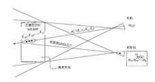
- FIG. 4 is a schematic diagram of a principle of a three-dimensional face reconstruction method S102 according to an embodiment of the present invention.
- FIG. 5 is a schematic diagram of a process flow of a three-dimensional face reconstruction method according to an embodiment of the present invention.
- FIG. 6 is a structural block diagram of a three-dimensional face reconstruction system according to an embodiment of the present invention.
- FIG. 1 is a flowchart showing an implementation process of a three-dimensional face reconstruction method according to an embodiment of the present invention, which is described in detail as follows:
- three-dimensional imaging units of the same configuration are respectively disposed on the left and right sides of the measured human face.
- each three-dimensional imaging unit is composed of a projector and an industrial camera, wherein the projector is regarded as a reverse camera, and the camera is connected to a computer through a GigE port, and the acquired image is transmitted to a computer for processing.
- the angle between the projector and the optical axis of the camera is approximately 30 degrees.
- the image projection action of the projector and the image capturing action of the camera are synchronously controlled by setting the projection acquisition control unit as shown in FIG. 2 .
- the three-dimensional imaging unit is dual-targeted, and a polynomial relationship between the three-dimensional point cloud coordinates acquired by the three-dimensional imaging unit and the corresponding phase is established according to the result of the dual target determination, and two three-dimensional relationships are determined.
- the transformation relationship between the three-dimensional point cloud coordinates acquired by the imaging unit is determined.
- the same calibration method is performed in the dual target setting process, and according to the dual target
- the result of the determination can determine the transformation relationship between the three-dimensional point cloud coordinates acquired by the two three-dimensional imaging units.
- the planar target with the reference point of the known three-dimensional coordinates is placed in different orientations, and the two three-dimensional imaging units are controlled to uniformly illuminate the target, and to project the phase shift and the Gray code structured light.
- the camera is controlled to capture the uniform illumination and deformation structure light images in each orientation.
- the polynomial relationship between the coordinates and phase of the 3D point cloud data is fitted to each 3D imaging unit.
- a point correspondence relationship between a camera position of the camera and a projection chip position of the projector and a system parameter of each of the three-dimensional imaging units are determined based on a preset binocular imaging model.
- the binocular imaging model determines the correspondence between the camera position m c and the projection chip position m p According to the binocular imaging model, system parameters (R cl , t cl , K cl , ⁇ cl , R sl , t sl , K pl , ⁇ pl ) and (R cr , t) of the left and right three-dimensional imaging units can be obtained respectively. Cr , K cr , ⁇ cr , R sr , t sr , K pr , ⁇ pr ).
- a ray emitted from the optical center and passing through the pixel is determined by the system parameter, and N different three-dimensional point cloud coordinates are sampled within a measurement range of the ray,
- the N is an integer greater than one.
- the three-dimensional point cloud coordinates are projected onto the projection chip, and the phase corresponding to the three-dimensional point cloud coordinates is obtained, and the three-dimensional point cloud coordinates acquired by the three-dimensional imaging unit are established and corresponding.
- the polynomial relationship between the phases is established and corresponding.
- phase distribution is obtained from the generated ideal stripes, which is independent of the three-dimensional scene and linearly distributed along the three-dimensional point cloud coordinates. Therefore, for the three-dimensional imaging unit that has completed the dual target setting, A closed interval continuous function can be used to represent the correspondence between the phase of each pixel and its three-dimensional point cloud coordinates. According to the Weierstrass approximation theorem, any closed-length continuous function can be approximated by polynomials. Therefore, phase is used.
- the polynomial coefficients a 0 , a 1 , a 2 ..., b 0 , b 1 , b 2 ..., c 0 , c 1 , c 2 ... represent the phase An n-th order polynomial mapping relationship with the three-dimensional point cloud coordinate X w (x w , y w , z w ).
- N are sampled within the measurement range of the ray, in order to obtain the corresponding points
- Absolute phase according to the binocular imaging model in S301, determine the position m pk (u p , v p ) of these sampling points in the projection chip (DMD chip), project the three-dimensional point cloud coordinates onto the projection chip, and according to the absolute Linear relationship between phase and projection chip position (where ⁇ is the spatial period of the phase-shifted stripe), the corresponding phase can be obtained Therefore, according to the Weierstrass approximation theorem, the correspondence between the phase and the three-dimensional coordinate points is as follows:
- the least squares solution of the overdetermined equation is used to determine the polynomial coefficients a 0 , a 1 , a 2 ..., b 0 , b 1 , b 2 ..., c 0 , c 1 , c 2 ..., thereby determining the polynomial relationship between the three-dimensional point cloud coordinates and the phase.
- R cl and T cl are the rotation matrix and translation matrix of the left three-dimensional imaging unit and the world coordinate system, respectively
- R cr and T cr are the rotation matrix and translation matrix of the right three-dimensional imaging unit and the world coordinate system
- R lr And T lr is used to respectively represent the mutual transformation relationship between the two three-dimensional imaging units for automatically matching the three-dimensional point cloud data between the two three-dimensional imaging units.
- an image sequence of the left and right sides of the measured human face is acquired by the three-dimensional imaging unit, and an absolute phase of the image sequence is obtained.
- the two three-dimensional imaging units are controlled to sequentially project the phase-shifted Gray coded structured light on the measured face, and simultaneously control the camera to acquire the deformed image sequence to obtain the absolute phase of the image sequence.
- k 1 and k 2 are respectively two different folding orders with complementary properties obtained by the complementary Gray code.
- the three-dimensional point cloud coordinates X w (y w , y w , z w corresponding to each different pixel position (i, j) in the camera can be obtained. ).
- the three-dimensional point cloud coordinates of the three-dimensional imaging unit are unified into a global coordinate system, and the three-dimensional reconstruction of the measured human face is completed.
- the three-dimensional point clouds X l and X r obtained on the left and right sides are matched to the global coordinate system, and the global coordinates can be based on the three-dimensional imaging unit on the left side. As follows:
- each pixel position is based on the acquired image sequence and the calibrated polynomial relationship.
- the 3D point cloud coordinates of the point can be obtained, and the parallelism is excellent. Therefore, the graphics processing unit (GPU) can be used to accelerate the calculation and obtain the 3D point cloud data of the entire camera area array in parallel.
- GPU graphics processing unit
- the process flow diagram of the above three-dimensional face reconstruction scheme can be as shown in FIG. 5.
- the process of searching for the corresponding point according to the conjugate sinus line and the phase value can be avoided, and the rapid three-dimensional reconstruction of the face is realized, and at the same time, the left and right sides are calibrated.
- the transformation relationship between the three-dimensional imaging units realizes the automatic matching of the three-dimensional data on the left and right sides, and improves the processing efficiency of the three-dimensional reconstruction of the face.
- FIG. 6 is a structural block diagram of a three-dimensional face reconstruction system provided by an embodiment of the present invention, where the three-dimensional face reconstruction system may be a software unit,
- a hardware unit is either a unit that combines hardware and software. For the convenience of explanation, only the parts related to the present embodiment are shown.
- the system includes:
- the setting unit 61 respectively sets three-dimensional imaging units of the same configuration on the left and right sides of the measured human face;
- the calibration unit 62 performs dual target determination on the three-dimensional imaging unit, and establishes a polynomial relationship between the three-dimensional point cloud coordinates acquired by the three-dimensional imaging unit and the corresponding phase according to the result of the dual target determination, and determines two three-dimensional relationships. a transformation relationship between the three-dimensional point cloud coordinates acquired by the imaging unit;
- the acquiring unit 63 is configured to acquire an image sequence of the left and right sides of the measured human face through the three-dimensional imaging unit, to obtain an absolute phase of the image sequence;
- the mapping unit 64 uses the polynomial relationship to map the absolute phase of the image sequence to a three-dimensional point cloud coordinate
- the reconstruction unit 65 integrates the three-dimensional point cloud coordinates of the three-dimensional imaging unit into the global coordinate system according to the transformation relationship, and completes the three-dimensional reconstruction of the measured human face.
- the setting unit 61 includes:
- Configuring a subunit configuring one projector and one camera for each of the three-dimensional imaging units, and using the projector as the camera opposite;
- the calibration unit 62 includes:
- Determining a subunit determining a point correspondence relationship between a camera position of the camera and a projection chip position of the projector and a system parameter of each of the three-dimensional imaging unit based on a preset binocular imaging model;
- a sampling subunit for a pixel point of an arbitrary pixel position of the camera, determining, by the system parameter, a ray that is emitted from the optical center and passes through the pixel, and samples N different three-dimensional point cloud coordinates within the measurement range of the ray;
- the calibration unit 62 is further configured to:
- R cl and T cl are the rotation matrix and translation matrix of the left three-dimensional imaging unit and the world coordinate system, respectively, and R cr and T cr are the rotation matrix and translation matrix of the right three-dimensional imaging unit and the world coordinate system, respectively, R lr And T lr are used to respectively represent the mutual transformation relationship between the two three-dimensional imaging units.
- system further includes:
- a parallel computing unit for processing each pixel in the sequence of images in parallel using a graphics processor GPU accelerated computation.
- each functional unit and module described above is exemplified. In practical applications, the above functions may be assigned to different functional units as needed.
- the module is completed by dividing the internal structure of the device into different functional units or modules to perform all or part of the functions described above.
- Each functional unit and module in the embodiment may be integrated into one processing unit, or each unit may exist physically separately, or two or more units may be integrated into one unit, and the integrated unit may be hardware.
- Formal implementation can also be implemented in the form of software functional units.
- the specific names of the respective functional units and modules are only for the purpose of facilitating mutual differentiation, and are not intended to limit the scope of protection of the present application.
- For the specific working process of the unit and the module in the foregoing system reference may be made to the corresponding process in the foregoing method embodiment, and details are not described herein again.
- the disclosed apparatus and method may be implemented in other manners.
- the system embodiments described above are merely illustrative, for example, The division of the module or unit is only a logical function division. In actual implementation, there may be another division manner. For example, multiple units or components may be combined or integrated into another system, or some features may be ignored, or carried out.
- the mutual coupling or direct coupling or communication connection shown or discussed may be an indirect coupling or communication connection through some interface, device or unit, and may be in electrical, mechanical or other form.
- the units described as separate components may or may not be physically separated, and the components displayed as units may or may not be physical units, that is, may be located in one place, or may be distributed to multiple network units. Some or all of the units may be selected according to actual needs to achieve the purpose of the solution of the embodiment.
- each functional unit in each embodiment of the present invention may be integrated into one processing unit, or each unit may exist physically separately, or two or more units may be integrated into one unit.
- the above integrated unit can be implemented in the form of hardware or in the form of a software functional unit.
- the integrated unit if implemented in the form of a software functional unit and sold or used as a standalone product, may be stored in a computer readable storage medium.
- the medium includes a plurality of instructions for causing a computer device (which may be a personal computer, a server, or a network device, etc.) or a processor to perform all or part of the steps of the methods described in various embodiments of the embodiments of the present invention.
- the foregoing storage medium includes: a U disk, a mobile hard disk, a read-only memory (ROM), a random access memory (RAM), a magnetic disk, or an optical disk, and the like. .
Landscapes
- Engineering & Computer Science (AREA)
- Physics & Mathematics (AREA)
- Theoretical Computer Science (AREA)
- General Physics & Mathematics (AREA)
- Computer Graphics (AREA)
- Geometry (AREA)
- Optics & Photonics (AREA)
- Computer Vision & Pattern Recognition (AREA)
- Computing Systems (AREA)
- Software Systems (AREA)
- Length Measuring Devices By Optical Means (AREA)
- Image Processing (AREA)
Abstract
Description


Claims (10)
- 一种三维人脸重建方法,其特征在于,包括:在被测人脸左右两侧分别设置相同配置的三维成像单元;对所述三维成像单元进行双目标定,根据双目标定的结果建立所述三维成像单元采集的三维点云坐标与对应的相位之间的多项式关系,并确定两个所述三维成像单元采集的三维点云坐标之间的变换关系;通过所述三维成像单元采集所述被测人脸左右两侧的图像序列,得到所述图像序列的绝对相位;利用所述多项式关系,将所述图像序列的绝对相位映射为三维点云坐标;根据所述变换关系,将所述三维成像单元的三维点云坐标统一至全局坐标系中,完成所述被测人脸的三维重建。
- 如权利要求1所述的方法,其特征在于,所述在被测人脸左右两侧分别设置相同配置的三维成像单元包括:为每个所述三维成像单元配置一个投影仪和一个相机,且将所述投影仪用做反向的所述相机;设置投影采集控制单元,用于同步控制所述投影仪的图像投射动作及所述相机的图像采集动作。
- 如权利要求2所述的方法,其特征在于,所述对所述三维成像单元进行双目标定,根据双目标定的结果建立所述三维成像单元采集的三维点云坐标与对应的相位之间的多项式关系包括:基于预设的双目成像模型,确定所述相机的相机位置与所述投影仪的投影芯片位置的点对应关系及每个所述三维成像单元的系统参数;对所述相机任意像素位置的像素点,由所述系统参数确定从光心射出并经过该像素的射线,在所述射线的测量范围内抽样N个不同的三维点云坐标;根据所述点对应关系,将所述三维点云坐标投影到所述投影芯片,得到所述三维点云坐标对应的相位,建立所述三维成像单元采集的三维点云坐标与对 应的相位之间的多项式关系。
- 如权利要求1所述的方法,其特征在于,所述确定两个所述三维成像单元采集的三维点云坐标之间的变换关系包括:确定所述变换关系为:
 其中,Rcl和Tcl分别为左侧三维成像单元与世界坐标系的旋转矩阵和平移矩阵,Rcr和Tcr分别为右侧三维成像单元与世界坐标系的旋转矩阵和平移矩阵,Rlr和Tlr用于分别表示两个三维成像单元之间的相互变换关系。
 - 如权利要求1所述的方法,其特征在于,所述方法还包括:利用图形处理器GPU加速计算并行处理所述图像序列中的每个像素。
- 一种三维人脸重建系统,其特征在于,包括:设置单元,用于在被测人脸左右两侧分别设置相同配置的三维成像单元;标定单元,用于对所述三维成像单元进行双目标定,根据双目标定的结果建立所述三维成像单元采集的三维点云坐标与对应的相位之间的多项式关系,并确定两个所述三维成像单元采集的三维点云坐标之间的变换关系;采集单元,用于通过所述三维成像单元采集所述被测人脸左右两侧的图像序列,得到所述图像序列的绝对相位;映射单元,用于利用所述多项式关系,将所述图像序列的绝对相位映射为三维点云坐标;重建单元,用于根据所述变换关系,将所述三维成像单元的三维点云坐标统一至全局坐标系中,完成所述被测人脸的三维重建。
- 如权利要求6所述的系统,其特征在于,所述设置单元包括:配置子单元,用于为每个所述三维成像单元配置一个投影仪和一个相机,且将所述投影仪用做反向的所述相机;设置子单元,用于设置投影采集控制单元,用于同步控制所述投影仪的图像投射动作及所述相机的图像采集动作。
- 如权利要求7所述的系统,其特征在于,所述标定单元包括:确定子单元,用于基于预设的双目成像模型,确定所述相机的相机位置与所述投影仪的投影芯片位置的点对应关系及每个所述三维成像单元的系统参数;抽样子单元,用于对所述相机任意像素位置的像素点,由所述系统参数确定从光心射出并经过该像素的射线,在所述射线的测量范围内抽样N个不同的三维点云坐标;建立子单元,用于根据所述点对应关系,将所述三维点云坐标投影到所述投影芯片,得到所述三维点云坐标对应的相位,建立所述三维成像单元采集的三维点云坐标与对应的相位之间的多项式关系。
- 如权利要求6所述的系统,其特征在于,所述标定单元还用于:确定所述变换关系为:
 其中,Rcl和Tcl分别为左侧三维成像单元与世界坐标系的旋转矩阵和平移矩阵,Rcr和Tcr分别为右侧三维成像单元与世界坐标系的旋转矩阵和平移矩阵,Rlr和Tlr用于分别表示两个三维成像单元之间的相互变换关系。
 - 如权利要求6所述的系统,其特征在于,所述系统还包括:并行计算单元,用于利用图形处理器GPU加速计算并行处理所述图像序列中的每个像素。
Priority Applications (3)
| Application Number | Priority Date | Filing Date | Title |
|---|---|---|---|
| CN201580008078.0A CN106164979B (zh) | 2015-07-13 | 2015-07-13 | 一种三维人脸重建方法及系统 |
| US15/114,649 US20170032565A1 (en) | 2015-07-13 | 2015-07-13 | Three-dimensional facial reconstruction method and system |
| PCT/CN2015/083889 WO2017008226A1 (zh) | 2015-07-13 | 2015-07-13 | 一种三维人脸重建方法及系统 |
Applications Claiming Priority (1)
| Application Number | Priority Date | Filing Date | Title |
|---|---|---|---|
| PCT/CN2015/083889 WO2017008226A1 (zh) | 2015-07-13 | 2015-07-13 | 一种三维人脸重建方法及系统 |
Publications (1)
| Publication Number | Publication Date |
|---|---|
| WO2017008226A1 true WO2017008226A1 (zh) | 2017-01-19 |
Family
ID=57348156
Family Applications (1)
| Application Number | Title | Priority Date | Filing Date |
|---|---|---|---|
| PCT/CN2015/083889 Ceased WO2017008226A1 (zh) | 2015-07-13 | 2015-07-13 | 一种三维人脸重建方法及系统 |
Country Status (3)
| Country | Link |
|---|---|
| US (1) | US20170032565A1 (zh) |
| CN (1) | CN106164979B (zh) |
| WO (1) | WO2017008226A1 (zh) |
Cited By (6)
| Publication number | Priority date | Publication date | Assignee | Title |
|---|---|---|---|---|
| CN109712200A (zh) * | 2019-01-10 | 2019-05-03 | 深圳大学 | 一种基于最小二乘原理及边长推算的双目定位方法及系统 |
| CN111080784A (zh) * | 2019-11-27 | 2020-04-28 | 贵州宽凳智云科技有限公司北京分公司 | 一种基于地面图像纹理的地面三维重建方法和装置 |
| CN111462331A (zh) * | 2020-03-31 | 2020-07-28 | 四川大学 | 扩展对极几何并实时计算三维点云的若干方法 |
| CN113706686A (zh) * | 2021-07-09 | 2021-11-26 | 苏州浪潮智能科技有限公司 | 一种三维点云重建结果补全方法及相关组件 |
| CN114459380A (zh) * | 2022-01-25 | 2022-05-10 | 清华大学深圳国际研究生院 | 一种获取折叠相位的方法、三维重建的方法及系统 |
| CN115063468A (zh) * | 2022-06-17 | 2022-09-16 | 梅卡曼德(北京)机器人科技有限公司 | 双目立体匹配方法、计算机存储介质以及电子设备 |
Families Citing this family (31)
| Publication number | Priority date | Publication date | Assignee | Title |
|---|---|---|---|---|
| CN106580472B (zh) * | 2016-12-12 | 2019-03-26 | 快创科技(大连)有限公司 | 一种基于ar虚拟现实技术的整形手术实时捕捉系统 |
| WO2018107427A1 (zh) * | 2016-12-15 | 2018-06-21 | 深圳大学 | 相位映射辅助三维成像系统快速对应点匹配的方法及装置 |
| CN106767405B (zh) * | 2016-12-15 | 2019-07-05 | 深圳大学 | 相位映射辅助三维成像系统快速对应点匹配的方法及装置 |
| CN106767533B (zh) * | 2016-12-28 | 2019-07-05 | 深圳大学 | 基于条纹投影轮廓术的高效相位-三维映射方法及系统 |
| CN107170010A (zh) * | 2017-05-11 | 2017-09-15 | 四川大学 | 系统校准方法、装置及三维重建系统 |
| CN108895969A (zh) * | 2018-05-23 | 2018-11-27 | 深圳大学 | 一种手机外壳的三维检测方法及装置 |
| CN109191505A (zh) * | 2018-08-03 | 2019-01-11 | 北京微播视界科技有限公司 | 静态生成人脸三维模型的方法、装置、电子设备 |
| CN109712228B (zh) * | 2018-11-19 | 2023-02-24 | 中国科学院深圳先进技术研究院 | 建立三维重建模型的方法、装置、电子设备及存储介质 |
| CN109840486B (zh) * | 2019-01-23 | 2023-07-21 | 深圳市中科晟达互联智能科技有限公司 | 专注度的检测方法、计算机存储介质和计算机设备 |
| CN109816791B (zh) * | 2019-01-31 | 2020-04-28 | 北京字节跳动网络技术有限公司 | 用于生成信息的方法和装置 |
| CN109903376B (zh) * | 2019-02-28 | 2022-08-09 | 四川川大智胜软件股份有限公司 | 一种人脸几何信息辅助的三维人脸建模方法及系统 |
| CN109903377B (zh) * | 2019-02-28 | 2022-08-09 | 四川川大智胜软件股份有限公司 | 一种无需相位展开的三维人脸建模方法及系统 |
| CN109978982B (zh) * | 2019-04-02 | 2023-04-07 | 广东电网有限责任公司 | 一种基于倾斜影像的点云快速上色方法 |
| CN110349257B (zh) * | 2019-07-16 | 2020-02-28 | 四川大学 | 一种基于相位伪映射的双目测量缺失点云插补方法 |
| CN113034345B (zh) * | 2019-12-25 | 2023-02-28 | 广东奥博信息产业股份有限公司 | 一种基于sfm重建的人脸识别方法及系统 |
| CN111179157B (zh) * | 2019-12-30 | 2023-09-05 | 东软集团股份有限公司 | 医学影像中面部区域的处理方法、装置及相关产品 |
| CN111325663B (zh) * | 2020-02-21 | 2023-11-28 | 深圳市易尚展示股份有限公司 | 基于并行架构的三维点云匹配方法、装置和计算机设备 |
| WO2021189303A1 (zh) * | 2020-03-25 | 2021-09-30 | 深圳市汇顶科技股份有限公司 | 数据采集装置、人脸识别装置、设备、方法及存储介质 |
| CN111462309B (zh) * | 2020-03-31 | 2023-12-19 | 深圳市新镜介网络有限公司 | 三维人头的建模方法、装置、终端设备及存储介质 |
| CN111583323B (zh) * | 2020-04-30 | 2023-04-25 | 深圳大学 | 一种单帧结构光场三维成像方法和系统 |
| CN111899326A (zh) * | 2020-06-18 | 2020-11-06 | 苏州小优智能科技有限公司 | 一种基于gpu并行加速的三维重建方法 |
| CN111932672B (zh) * | 2020-09-14 | 2021-03-09 | 江苏原力数字科技股份有限公司 | 一种基于机器学习自动生成超写实3d面部模型的方法 |
| CN112099002B (zh) * | 2020-09-18 | 2021-07-27 | 欧必翼太赫兹科技(北京)有限公司 | 三维异形平面孔径全息成像安检雷达光学重建方法 |
| CN113345039B (zh) * | 2021-03-30 | 2022-10-28 | 西南电子技术研究所(中国电子科技集团公司第十研究所) | 三维重建量化结构光相位图像编码方法 |
| CN112884889B (zh) * | 2021-04-06 | 2022-05-20 | 北京百度网讯科技有限公司 | 模型训练、人头重建方法,装置,设备以及存储介质 |
| CN114119549B (zh) * | 2021-11-26 | 2023-08-29 | 卡本(深圳)医疗器械有限公司 | 一种多模态医学图像三维点云配准优化方法 |
| CN115406371B (zh) * | 2022-09-01 | 2025-01-07 | 安徽大学 | 一种基于dic的柔性指尖形变测量方法 |
| CN116664796B (zh) * | 2023-04-25 | 2024-04-02 | 北京天翔睿翼科技有限公司 | 轻量级头部建模系统及方法 |
| CN117058233A (zh) * | 2023-07-31 | 2023-11-14 | 宁波江丰生物信息技术有限公司 | 基于三维反投影的取材指导方法、存储介质及系统 |
| CN116862999B (zh) * | 2023-09-04 | 2023-12-08 | 华东交通大学 | 一种双摄像机三维测量的标定方法、系统、设备和介质 |
| CN116993948B (zh) * | 2023-09-26 | 2024-03-26 | 粤港澳大湾区数字经济研究院(福田) | 一种人脸三维重建方法、系统及智能终端 |
Citations (6)
| Publication number | Priority date | Publication date | Assignee | Title |
|---|---|---|---|---|
| CN101101672A (zh) * | 2007-07-13 | 2008-01-09 | 中国科学技术大学 | 基于虚拟图像对应的立体视觉三维人脸建模方法 |
| CN101466998A (zh) * | 2005-11-09 | 2009-06-24 | 几何信息学股份有限公司 | 三维绝对坐标表面成像的方法和装置 |
| CN101866497A (zh) * | 2010-06-18 | 2010-10-20 | 北京交通大学 | 基于双目立体视觉的智能三维人脸重建方法及系统 |
| CN102175179A (zh) * | 2011-02-23 | 2011-09-07 | 东南大学 | 一种人体表面轮廓三维重建的方法与装置 |
| US20120275667A1 (en) * | 2011-04-29 | 2012-11-01 | Aptina Imaging Corporation | Calibration for stereoscopic capture system |
| CN103971408A (zh) * | 2014-05-21 | 2014-08-06 | 中国科学院苏州纳米技术与纳米仿生研究所 | 三维人脸模型生成系统及方法 |
Family Cites Families (9)
| Publication number | Priority date | Publication date | Assignee | Title |
|---|---|---|---|---|
| JP2003269928A (ja) * | 2002-03-12 | 2003-09-25 | Nec Corp | 3次元形状計測方法および装置ならびにプログラム |
| US6701006B2 (en) * | 2002-06-26 | 2004-03-02 | Nextengine, Inc. | Apparatus and method for point cloud assembly |
| US8050491B2 (en) * | 2003-12-17 | 2011-11-01 | United Technologies Corporation | CAD modeling system and method |
| US7769205B2 (en) * | 2006-11-28 | 2010-08-03 | Prefixa International Inc. | Fast three dimensional recovery method and apparatus |
| PL2438397T3 (pl) * | 2009-06-01 | 2019-05-31 | Dentsply Sirona Inc | Sposób i urządzenie do trójwymiarowej detekcji powierzchni z dynamiczną ramką odniesienia |
| GB2483285A (en) * | 2010-09-03 | 2012-03-07 | Marc Cardle | Relief Model Generation |
| US8587583B2 (en) * | 2011-01-31 | 2013-11-19 | Microsoft Corporation | Three-dimensional environment reconstruction |
| CN102654391B (zh) * | 2012-01-17 | 2014-08-20 | 深圳大学 | 基于光束平差原理的条纹投影三维测量系统及其标定方法 |
| CN102945565B (zh) * | 2012-10-18 | 2016-04-06 | 深圳大学 | 一种物体的三维真实感重建方法、系统及电子设备 |
-
2015
- 2015-07-13 WO PCT/CN2015/083889 patent/WO2017008226A1/zh not_active Ceased
- 2015-07-13 US US15/114,649 patent/US20170032565A1/en not_active Abandoned
- 2015-07-13 CN CN201580008078.0A patent/CN106164979B/zh active Active
Patent Citations (6)
| Publication number | Priority date | Publication date | Assignee | Title |
|---|---|---|---|---|
| CN101466998A (zh) * | 2005-11-09 | 2009-06-24 | 几何信息学股份有限公司 | 三维绝对坐标表面成像的方法和装置 |
| CN101101672A (zh) * | 2007-07-13 | 2008-01-09 | 中国科学技术大学 | 基于虚拟图像对应的立体视觉三维人脸建模方法 |
| CN101866497A (zh) * | 2010-06-18 | 2010-10-20 | 北京交通大学 | 基于双目立体视觉的智能三维人脸重建方法及系统 |
| CN102175179A (zh) * | 2011-02-23 | 2011-09-07 | 东南大学 | 一种人体表面轮廓三维重建的方法与装置 |
| US20120275667A1 (en) * | 2011-04-29 | 2012-11-01 | Aptina Imaging Corporation | Calibration for stereoscopic capture system |
| CN103971408A (zh) * | 2014-05-21 | 2014-08-06 | 中国科学院苏州纳米技术与纳米仿生研究所 | 三维人脸模型生成系统及方法 |
Cited By (8)
| Publication number | Priority date | Publication date | Assignee | Title |
|---|---|---|---|---|
| CN109712200A (zh) * | 2019-01-10 | 2019-05-03 | 深圳大学 | 一种基于最小二乘原理及边长推算的双目定位方法及系统 |
| CN111080784A (zh) * | 2019-11-27 | 2020-04-28 | 贵州宽凳智云科技有限公司北京分公司 | 一种基于地面图像纹理的地面三维重建方法和装置 |
| CN111080784B (zh) * | 2019-11-27 | 2024-04-19 | 贵州宽凳智云科技有限公司北京分公司 | 一种基于地面图像纹理的地面三维重建方法和装置 |
| CN111462331A (zh) * | 2020-03-31 | 2020-07-28 | 四川大学 | 扩展对极几何并实时计算三维点云的若干方法 |
| CN113706686A (zh) * | 2021-07-09 | 2021-11-26 | 苏州浪潮智能科技有限公司 | 一种三维点云重建结果补全方法及相关组件 |
| CN113706686B (zh) * | 2021-07-09 | 2023-07-21 | 苏州浪潮智能科技有限公司 | 一种三维点云重建结果补全方法及相关组件 |
| CN114459380A (zh) * | 2022-01-25 | 2022-05-10 | 清华大学深圳国际研究生院 | 一种获取折叠相位的方法、三维重建的方法及系统 |
| CN115063468A (zh) * | 2022-06-17 | 2022-09-16 | 梅卡曼德(北京)机器人科技有限公司 | 双目立体匹配方法、计算机存储介质以及电子设备 |
Also Published As
| Publication number | Publication date |
|---|---|
| CN106164979A (zh) | 2016-11-23 |
| CN106164979B (zh) | 2019-05-17 |
| US20170032565A1 (en) | 2017-02-02 |
Similar Documents
| Publication | Publication Date | Title |
|---|---|---|
| CN106164979B (zh) | 一种三维人脸重建方法及系统 | |
| CN113012277B (zh) | 一种基于dlp面结构光多相机重建方法 | |
| CN108876926B (zh) | 一种全景场景中的导航方法及系统、ar/vr客户端设备 | |
| CN110288642B (zh) | 基于相机阵列的三维物体快速重建方法 | |
| CN107170043B (zh) | 一种三维重建方法 | |
| CN103971408B (zh) | 三维人脸模型生成系统及方法 | |
| Schmalz et al. | An endoscopic 3D scanner based on structured light | |
| CN102072706B (zh) | 一种多相机定位与跟踪方法及系统 | |
| CN108269300A (zh) | 牙齿三维数据重建方法、装置和系统 | |
| JP2019516983A (ja) | 3次元走査システムおよびその走査方法 | |
| WO2016037486A1 (zh) | 人体三维成像方法及系统 | |
| CN107393011A (zh) | 一种基于多结构光视觉技术的快速三维虚拟试衣系统和方法 | |
| Li et al. | Binocular stereo vision calibration based on alternate adjustment algorithm | |
| CN116958233A (zh) | 基于多波段红外结构光系统的皮肤烧伤面积计算方法 | |
| CN112294453B (zh) | 一种显微手术术野三维重建系统及方法 | |
| Mahdy et al. | Projector calibration using passive stereo and triangulation | |
| CN107038753A (zh) | 立体视觉三维重建系统及方法 | |
| CN110458960A (zh) | 一种基于偏振的彩色物体三维重建方法 | |
| Wilm et al. | Accurate and simple calibration of DLP projector systems | |
| CN104794718A (zh) | 一种单图像ct机房监控摄像机标定的方法 | |
| KR102585129B1 (ko) | 픽셀 빔을 나타내는 데이터를 생성하기 위한 장치 및 방법 | |
| CN111739103A (zh) | 一种基于单点标定物的多相机标定系统 | |
| US9621875B2 (en) | Device for the acquisition of a stereoscopy image pair | |
| Castaneda et al. | Stereo time-of-flight | |
| RU2729698C2 (ru) | Устройство и способ для кодирования изображения, захваченного оптической системой получения данных |
Legal Events
| Date | Code | Title | Description |
|---|---|---|---|
| WWE | Wipo information: entry into national phase |
Ref document number: 15114649 Country of ref document: US |
|
| 121 | Ep: the epo has been informed by wipo that ep was designated in this application |
Ref document number: 15897954 Country of ref document: EP Kind code of ref document: A1 |
|
| NENP | Non-entry into the national phase |
Ref country code: DE |
|
| 32PN | Ep: public notification in the ep bulletin as address of the adressee cannot be established |
Free format text: NOTING OF LOSS OF RIGHTS PURSUANT TO RULE 112(1) EPC (EPO FORM 1205A DATED 01.06.2018) |
|
| 122 | Ep: pct application non-entry in european phase |
Ref document number: 15897954 Country of ref document: EP Kind code of ref document: A1 |