WO2017006882A1 - Dispositif terminal, dispositif à station de base, procédé de communication et circuit intégré - Google Patents
Dispositif terminal, dispositif à station de base, procédé de communication et circuit intégré Download PDFInfo
- Publication number
- WO2017006882A1 WO2017006882A1 PCT/JP2016/069706 JP2016069706W WO2017006882A1 WO 2017006882 A1 WO2017006882 A1 WO 2017006882A1 JP 2016069706 W JP2016069706 W JP 2016069706W WO 2017006882 A1 WO2017006882 A1 WO 2017006882A1
- Authority
- WO
- WIPO (PCT)
- Prior art keywords
- layers
- maximum number
- information
- terminal device
- downlink
- Prior art date
Links
Images


Classifications
-
- H—ELECTRICITY
- H04—ELECTRIC COMMUNICATION TECHNIQUE
- H04B—TRANSMISSION
- H04B7/00—Radio transmission systems, i.e. using radiation field
- H04B7/02—Diversity systems; Multi-antenna system, i.e. transmission or reception using multiple antennas
- H04B7/04—Diversity systems; Multi-antenna system, i.e. transmission or reception using multiple antennas using two or more spaced independent antennas
- H04B7/06—Diversity systems; Multi-antenna system, i.e. transmission or reception using multiple antennas using two or more spaced independent antennas at the transmitting station
- H04B7/0613—Diversity systems; Multi-antenna system, i.e. transmission or reception using multiple antennas using two or more spaced independent antennas at the transmitting station using simultaneous transmission
- H04B7/0615—Diversity systems; Multi-antenna system, i.e. transmission or reception using multiple antennas using two or more spaced independent antennas at the transmitting station using simultaneous transmission of weighted versions of same signal
- H04B7/0619—Diversity systems; Multi-antenna system, i.e. transmission or reception using multiple antennas using two or more spaced independent antennas at the transmitting station using simultaneous transmission of weighted versions of same signal using feedback from receiving side
- H04B7/0621—Feedback content
- H04B7/063—Parameters other than those covered in groups H04B7/0623 - H04B7/0634, e.g. channel matrix rank or transmit mode selection
-
- H—ELECTRICITY
- H04—ELECTRIC COMMUNICATION TECHNIQUE
- H04B—TRANSMISSION
- H04B7/00—Radio transmission systems, i.e. using radiation field
- H04B7/02—Diversity systems; Multi-antenna system, i.e. transmission or reception using multiple antennas
- H04B7/04—Diversity systems; Multi-antenna system, i.e. transmission or reception using multiple antennas using two or more spaced independent antennas
- H04B7/0413—MIMO systems
- H04B7/0456—Selection of precoding matrices or codebooks, e.g. using matrices antenna weighting
- H04B7/0486—Selection of precoding matrices or codebooks, e.g. using matrices antenna weighting taking channel rank into account
-
- H—ELECTRICITY
- H04—ELECTRIC COMMUNICATION TECHNIQUE
- H04L—TRANSMISSION OF DIGITAL INFORMATION, e.g. TELEGRAPHIC COMMUNICATION
- H04L1/00—Arrangements for detecting or preventing errors in the information received
- H04L1/12—Arrangements for detecting or preventing errors in the information received by using return channel
- H04L1/16—Arrangements for detecting or preventing errors in the information received by using return channel in which the return channel carries supervisory signals, e.g. repetition request signals
- H04L1/18—Automatic repetition systems, e.g. Van Duuren systems
- H04L1/1812—Hybrid protocols; Hybrid automatic repeat request [HARQ]
-
- H—ELECTRICITY
- H04—ELECTRIC COMMUNICATION TECHNIQUE
- H04L—TRANSMISSION OF DIGITAL INFORMATION, e.g. TELEGRAPHIC COMMUNICATION
- H04L1/00—Arrangements for detecting or preventing errors in the information received
- H04L1/12—Arrangements for detecting or preventing errors in the information received by using return channel
- H04L1/16—Arrangements for detecting or preventing errors in the information received by using return channel in which the return channel carries supervisory signals, e.g. repetition request signals
- H04L1/18—Automatic repetition systems, e.g. Van Duuren systems
- H04L1/1822—Automatic repetition systems, e.g. Van Duuren systems involving configuration of automatic repeat request [ARQ] with parallel processes
-
- H—ELECTRICITY
- H04—ELECTRIC COMMUNICATION TECHNIQUE
- H04L—TRANSMISSION OF DIGITAL INFORMATION, e.g. TELEGRAPHIC COMMUNICATION
- H04L1/00—Arrangements for detecting or preventing errors in the information received
- H04L1/12—Arrangements for detecting or preventing errors in the information received by using return channel
- H04L1/16—Arrangements for detecting or preventing errors in the information received by using return channel in which the return channel carries supervisory signals, e.g. repetition request signals
- H04L1/18—Automatic repetition systems, e.g. Van Duuren systems
- H04L1/1829—Arrangements specially adapted for the receiver end
- H04L1/1835—Buffer management
-
- H—ELECTRICITY
- H04—ELECTRIC COMMUNICATION TECHNIQUE
- H04L—TRANSMISSION OF DIGITAL INFORMATION, e.g. TELEGRAPHIC COMMUNICATION
- H04L49/00—Packet switching elements
- H04L49/90—Buffering arrangements
-
- H—ELECTRICITY
- H04—ELECTRIC COMMUNICATION TECHNIQUE
- H04L—TRANSMISSION OF DIGITAL INFORMATION, e.g. TELEGRAPHIC COMMUNICATION
- H04L5/00—Arrangements affording multiple use of the transmission path
- H04L5/0001—Arrangements for dividing the transmission path
- H04L5/0014—Three-dimensional division
- H04L5/0023—Time-frequency-space
-
- H—ELECTRICITY
- H04—ELECTRIC COMMUNICATION TECHNIQUE
- H04W—WIRELESS COMMUNICATION NETWORKS
- H04W16/00—Network planning, e.g. coverage or traffic planning tools; Network deployment, e.g. resource partitioning or cells structures
- H04W16/24—Cell structures
- H04W16/28—Cell structures using beam steering
-
- H—ELECTRICITY
- H04—ELECTRIC COMMUNICATION TECHNIQUE
- H04W—WIRELESS COMMUNICATION NETWORKS
- H04W28/00—Network traffic management; Network resource management
- H04W28/02—Traffic management, e.g. flow control or congestion control
- H04W28/04—Error control
-
- H—ELECTRICITY
- H04—ELECTRIC COMMUNICATION TECHNIQUE
- H04W—WIRELESS COMMUNICATION NETWORKS
- H04W72/00—Local resource management
- H04W72/04—Wireless resource allocation
-
- H—ELECTRICITY
- H04—ELECTRIC COMMUNICATION TECHNIQUE
- H04W—WIRELESS COMMUNICATION NETWORKS
- H04W8/00—Network data management
- H04W8/22—Processing or transfer of terminal data, e.g. status or physical capabilities
- H04W8/24—Transfer of terminal data
Definitions
- the present invention relates to a terminal device, a base station device, a communication method, and an integrated circuit.
- LTE Long Term Evolution
- EUTRA Evolved Universal Terrestrial Radio Access
- 3GPP Third Generation Partnership Project
- a base station apparatus is also called eNodeB (evolvedvolveNodeB), and a terminal device is also called UE (UserUEEquipment).
- LTE is a cellular communication system in which a plurality of areas covered by a base station apparatus are arranged in a cell shape. A single base station apparatus may manage a plurality of cells.
- LTE introduces carrier aggregation that communicates with a base station apparatus via a plurality of carriers (cells) in which terminal apparatuses are aggregated, and MIMO (Multiple Input Input Multiple Output) in which a plurality of layers are spatially multiplexed.
- MIMO Multiple Input Input Multiple Output
- LTE release 8 and carrier aggregation is introduced from LTE release 10 (Non-Patent Documents 2, 3, and 4).
- the terminal device transmits capability information indicating MIMO and carrier aggregation technology supported by the terminal device to the base station device (Non-Patent Document 5).
- the actual operation of the base station device and the operation of the base station device assumed by the terminal device may be different, and the base station device and the terminal device may not communicate correctly.
- the actual operation of the base station apparatus with respect to the bit width of RI (Rank Indicator) that the terminal apparatus feeds back to the base station apparatus, the rate matching of code blocks of the downlink transport block, the store of soft channel bits,
- RI Rank Indicator
- the operation of the base station device assumed by the terminal device and / or the actual operation of the terminal device and the operation of the terminal device assumed by the base station device are different.
- the present invention has been made in view of the above points, and an object thereof is to provide a terminal device, a base station device, a communication method, and an integrated circuit that can efficiently communicate with the base station device. is there.
- the aspect of the present invention takes the following measures. That is, the first aspect of the present invention is a terminal apparatus, which transmits a RI (Rank (Indicator) for PDSCH (Physical Downlink Shared CHannel) transmission, and for determining a bit width for the RI.
- a receiving unit that receives first information used to determine the first maximum number of layers, and receives a transport block on the PDSCH;
- a decoding unit that decodes the code block, and when the decoding unit fails to decode the code block, stores a soft channel bit corresponding to a range of at least a predetermined soft channel bit, and The soft channel bits are based on the soft buffer size for the code block, and the soft buffer bit for the code block.
- File size at least, based on the first information used for the determination of the maximum number of the first of said layer.
- a second aspect of the present invention is a communication method used for a terminal apparatus, which transmits an RI (Rank Indicator) for PDSCH (Physical Downlink Shared CHannel) transmission and determines a bit width for the RI Receiving the first information used for determining the first maximum number of layers, receiving the transport block on the PDSCH, and the transport block If the code block is decoded and the decoding of the code block fails, at least a soft channel bit corresponding to a predetermined soft channel bit range is stored, and the predetermined soft channel bit is a soft buffer size for the code block.
- the soft buffer size for the code block is at least the ray block. Based on the first information used for the first determination of the maximum number of over.
- a third aspect of the present invention is an integrated circuit for transmitting a RI (Rank (Indicator) for PDSCH (Physical Downlink Shared CHannel) transmission and for determining a bit width for the RI.
- RI Rank (Indicator) for PDSCH (Physical Downlink Shared CHannel) transmission and for determining a bit width for the RI.
- a first maximum number assumed, a function of receiving first information used for determining the first maximum number of layers, a function of receiving a transport block on the PDSCH, and the transport A terminal device exhibits a series of functions including a function of decoding a code block of a block and a function of storing at least a soft channel bit corresponding to a predetermined soft channel bit range when decoding of the code block fails.
- the predetermined soft channel bit is based on a soft buffer size for the code block.
- Soft buffer size for click is at least, based on the first information used for the determination of the maximum number of the first of said layer.
- the terminal device and the base station device can communicate efficiently.
- a plurality of cells are set in the terminal device.
- a technique in which a terminal device communicates via a plurality of cells is referred to as cell aggregation or carrier aggregation.
- the present invention may be applied to each of a plurality of cells set for a terminal device. Further, the present invention may be applied to some of the plurality of set cells.
- a cell set in the terminal device is also referred to as a serving cell.
- TDD Time Division Division Duplex
- FDD Frequency Division Duplex
- the set serving cells include one primary cell (PCell) and one or more secondary cells (SCell).
- the primary cell is a serving cell in which an initial connection establishment (initial connection establishment) procedure is performed, a serving cell that starts a connection reestablishment (connection (re-establishment) procedure, or a cell designated as a primary cell in a handover procedure.
- the secondary cell may be set at the time when the RRC connection is established or afterwards.
- a carrier corresponding to a cell is referred to as a downlink component carrier.
- a carrier corresponding to a cell is referred to as an uplink component carrier.
- the component carrier includes a transmission bandwidth setting.
- the transmission bandwidth settings are 1.4 MHz, 5 MHz, 10 MHz, 15 MHz, and 20 MHz.
- FIG. 1 is a conceptual diagram of the wireless communication system of the present embodiment.
- the radio communication system includes terminal apparatuses 1A to 1C and a base station apparatus 3.
- the terminal devices 1A to 1C are referred to as the terminal device 1.
- the following uplink physical channels are used in uplink wireless communication from the terminal device 1 to the base station device 3.
- the uplink physical channel is used for transmitting information output from an upper layer.
- -PUCCH Physical Uplink Control Channel
- PUSCH Physical Uplink Shared Channel
- PRACH Physical Random Access Channel
- Uplink Control Information is a physical channel used for transmitting uplink control information (Uplink Control Information: UCI).
- Uplink control information includes downlink channel state information (Channel State Information: CSI), scheduling request (Scheduling Request: SR) indicating a PUSCH resource request, downlink data (Transport block, Downlink-Shared Channel, DL-SCH).
- ACK acknowledgenowledgement
- NACK negative-acknowledgement
- ACK / NACK is also referred to as HARQ-ACK, HARQ feedback, or response information.
- the channel state information includes a channel quality index (Channel Quality Indicator: CQI), RI (Rank Index), and PMI (Precoding Matrix Indicator).
- CQI expresses a combination of a modulation scheme and a coding rate for a single transport block transmitted on the PDSCH.
- RI indicates the number of useful layers determined by the terminal device 1.
- PMI indicates a code book determined by the terminal device 1.
- the codebook is related to PDSCH precoding.
- the PUSCH is a physical channel used to transmit uplink data (Uplink-Shared Channel: UL-SCH).
- the PUSCH may also be used to transmit HARQ-ACK and / or channel state information along with uplink data. Also, the PUSCH may be used to transmit only channel state information or only HARQ-ACK and channel state information.
- PRACH is a physical channel used to transmit a random access preamble.
- uplink physical signals are used in uplink wireless communication.
- the uplink physical signal is not used for transmitting information output from the upper layer, but is used by the physical layer.
- UL RS Uplink Reference Signal
- DMRS Demodulation Reference Signal
- SRS Sounding Reference Signal
- DMRS is related to transmission of PUSCH or PUCCH.
- SRS is not related to PUSCH or PUCCH transmission.
- the following downlink physical channels are used in downlink radio communication from the base station apparatus 3 to the terminal apparatus 1.
- the downlink physical channel is used for transmitting information output from an upper layer.
- PBCH Physical Broadcast Channel
- PCFICH Physical Control Format Indicator Channel
- PHICH Physical Hybrid automatic repeat request Indicator Channel
- PDCCH Physical Downlink Control Channel
- EPDCCH Enhanced Physical Downlink Control Channel
- PDSCH Physical Downlink Shared Channel
- PMCH Physical Multicast Channel
- the PBCH is used to broadcast a master information block (Master Information Block: MIB, Broadcast Channel: BCH) commonly used in the terminal device 1.
- SFN system frame number
- MIB is system information. For example, the MIB includes information indicating SFN.
- PBCH is transmitted in a part or all of transmit antenna ports 0 to 3.
- PCFICH is used for transmitting information indicating a region (OFDM symbol) used for transmission of PDCCH.
- the PHICH is used to transmit an HARQ indicator (HARQ feedback, response information) indicating ACK (ACKnowledgement) or NACK (Negative ACKnowledgement) for uplink data (Uplink Shared Channel: UL-SCH) received by the base station apparatus 3. It is done.
- HARQ indicator HARQ feedback, response information
- ACK acknowledgement
- NACK Negative ACKnowledgement
- the PDCCH and EPDCCH are used to transmit downlink control information (Downlink Control Information: DCI).
- DCI Downlink Control Information
- the downlink control information is also referred to as a DCI format.
- the downlink control information includes a downlink grant (downlink grant) and an uplink grant (uplink grant).
- the downlink grant is also referred to as downlink assignment (downlink allocation) or downlink assignment (downlink allocation).
- the downlink grant is used for scheduling a single PDSCH within a single cell.
- the downlink grant is used for scheduling the PDSCH in the same subframe as the subframe in which the downlink grant is transmitted.
- the uplink grant is used for scheduling a single PUSCH within a single cell.
- the uplink grant is used for scheduling a single PUSCH in a subframe that is four or more after the subframe in which the uplink grant is transmitted.
- CRC Cyclic Redundancy Check
- CRC parity bits are scrambled by C-RNTI (Cell-Radio Network Temporary Identifier) or SPS C-RNTI (Semi-Persistent Scheduling Cell-Radio Network Temporary Identifier).
- C-RNTI and SPS C-RNTI are identifiers for identifying the terminal device 1 in the cell.
- C-RNTI is used to control PDSCH or PUSCH in a single subframe.
- the SPS C-RNTI is used to periodically allocate PDSCH or PUSCH resources.
- PDSCH is used to transmit downlink data (Downlink Shared Channel: DL-SCH).
- PMCH is used to transmit multicast data (Multicast Channel: MCH).
- the following downlink physical signals are used in downlink wireless communication.
- the downlink physical signal is not used for transmitting information output from the upper layer, but is used by the physical layer.
- SS Synchronization signal
- DL RS Downlink Reference Signal
- the synchronization signal is used for the terminal device 1 to synchronize the downlink frequency domain and time domain.
- the downlink reference signal is used for the terminal device 1 to correct the propagation path of the downlink physical channel.
- the downlink reference signal is used for the terminal device 1 to calculate downlink channel state information.
- the following five types of downlink reference signals are used.
- -CRS Cell-specific Reference Signal
- URS UE-specific Reference Signal
- PDSCH PDSCH
- DMRS Demodulation Reference Signal
- EPDCCH Non-Zero Power Chanel State Information-Reference Signal
- ZP CSI-RS Zero Power Chanel State Information-Reference Signal
- MBSFN RS Multimedia Broadcast and Multicast Service over Single Frequency Network Reference signal
- PRS Positioning Reference Signal
- CRS is transmitted in the entire bandwidth of the subframe.
- CRS is used to demodulate PBCH / PDCCH / PHICH / PCFICH / PDSCH.
- the CRS may be used for the terminal device 1 to calculate downlink channel state information.
- PBCH / PDCCH / PHICH / PCFICH is transmitted through an antenna port used for CRS transmission.
- URS related to PDSCH is transmitted in a subframe and a band used for transmission of PDSCH related to URS.
- URS is used to demodulate the PDSCH with which the URS is associated.
- the PDSCH is transmitted through an antenna port used for CRS or URS transmission.
- the DCI format 1A is used for scheduling of PDSCH transmitted through an antenna port used for CRS transmission.
- the DCI format 2B, the DCI format 2C, and the DCI format 2D are used for scheduling of PDSCH transmitted by an antenna port used for URS transmission.
- DMRS related to EPDCCH is transmitted in subframes and bands used for transmission of EPDCCH related to DMRS.
- DMRS is used to demodulate the EPDCCH with which DMRS is associated.
- the EPDCCH is transmitted through an antenna port used for DMRS transmission.
- NZP CSI-RS is transmitted in the set subframe.
- the resource for transmitting the NZP CSI-RS is set by the base station apparatus.
- the NZP CSI-RS is used by the terminal device 1 to calculate downlink channel state information.
- the terminal device 1 performs signal measurement (channel measurement) using NZP CSI-RS.
- the NZP CSI-RS is transmitted in a part or all of the transmission antenna ports 15 to 22.
- the terminal device 1 sets / specifies a transmission antenna port for NZP CSI-RS transmission based on the information received from the base station device 3.
- ZP CSI-RS resources are set by the base station device 3.
- the base station apparatus 3 transmits ZP CSI-RS with zero output. That is, the base station apparatus 3 does not transmit ZP CSI-RS.
- the base station apparatus 3 does not transmit PDSCH and EPDCCH in the resource set by ZP CSI-RS.
- the terminal device 1 can measure interference in a resource supported by NZP CSI-RS in a certain cell.
- the MBSFN RS is transmitted in the entire band of the subframe used for PMCH transmission.
- the MBSFN RS is used for PMCH demodulation.
- PMCH is transmitted through an antenna port used for transmission of MBSFN RS.
- PRS may be used for RSTD (Reference Signal Signal Time Difference) measurement.
- the RSTD is defined by a relative timing difference between a neighbor cell and a reference cell.
- the downlink physical channel and the downlink physical signal are collectively referred to as a downlink signal.
- the uplink physical channel and the uplink physical signal are collectively referred to as an uplink signal.
- the downlink physical channel and the uplink physical channel are collectively referred to as a physical channel.
- the downlink physical signal and the uplink physical signal are collectively referred to as a physical signal.
- BCH, MCH, UL-SCH and DL-SCH are transport channels.
- a channel used in a medium access control (Medium Access Control: MAC) layer is referred to as a transport channel.
- a transport channel unit used in the MAC layer is also referred to as a transport block (transport block: TB) or a MAC PDU (Protocol Data Unit).
- HARQ HybridbrAutomatic Repeat reQuest
- the transport block is a unit of data that the MAC layer delivers to the physical layer.
- the transport block is mapped to a code word, and an encoding process is performed for each code word.
- FIG. 2 is a diagram illustrating a schematic configuration of a radio frame according to the present embodiment.
- Each radio frame is 10 ms long.
- the horizontal axis is a time axis.
- Each radio frame is composed of two half frames.
- Each half frame is 5 ms long.
- Each half frame is composed of 5 subframes.
- Each subframe is 1 ms long and is defined by two consecutive slots.
- Each of the slots is 0.5 ms long.
- the i-th subframe in the radio frame is composed of a (2 ⁇ i) th slot and a (2 ⁇ i + 1) th slot. That is, 10 subframes can be used in each 10 ms interval.
- subframes In this embodiment, the following three types of subframes are defined. -Downlink subframe (first subframe) -Uplink subframe (second subframe) Special subframe (third subframe)
- the downlink subframe is a subframe reserved for downlink transmission.
- the uplink subframe is a subframe reserved for uplink transmission.
- the special subframe is composed of three fields. The three fields are DwPTS (Downlink Pilot Time Slot), GP (Guard Period), and UpPTS (Uplink Pilot Time Slot). The total length of DwPTS, GP, and UpPTS is 1 ms.
- DwPTS is a field reserved for downlink transmission.
- UpPTS is a field reserved for uplink transmission.
- GP is a field in which downlink transmission and uplink transmission are not performed. Note that the special subframe may be composed of only DwPTS and GP, or may be composed of only GP and UpPTS.
- a single radio frame is composed of at least a downlink subframe, an uplink subframe, and a special subframe.
- the wireless communication system of this embodiment supports 5 ms and 10 ms downlink-uplink-switch-point-periodicity.
- the downlink-uplink switch point period is 5 ms
- a special subframe is included in both half frames in the radio frame.
- the downlink-uplink switch point period is 10 ms
- a special subframe is included only in the first half frame in the radio frame.
- FIG. 3 is a diagram showing the configuration of the slot according to the present embodiment.
- normal CP normal Cyclic Prefix
- An extended CP extendedexCyclic Prefix
- the physical signal or physical channel transmitted in each of the slots is represented by a resource grid.
- the horizontal axis is a time axis
- the vertical axis is a frequency axis.
- the resource grid is defined by a plurality of subcarriers and a plurality of OFDM symbols.
- the resource grid is defined by a plurality of subcarriers and a plurality of SC-FDMA symbols.
- the number of subcarriers constituting one slot depends on the cell bandwidth.
- the number of OFDM symbols or SC-FDMA symbols constituting one slot is seven.
- Each element in the resource grid is referred to as a resource element.
- the resource element is identified using a subcarrier number and an OFDM symbol or SC-FDMA symbol number.
- the resource block is used to express mapping of a certain physical channel (such as PDSCH or PUSCH) to a resource element.
- resource blocks virtual resource blocks and physical resource blocks are defined.
- a physical channel is first mapped to a virtual resource block. Thereafter, the virtual resource block is mapped to the physical resource block.
- One physical resource block is defined by 7 consecutive OFDM symbols or SC-FDMA symbols in the time domain and 12 consecutive subcarriers in the frequency domain. Therefore, one physical resource block is composed of (7 ⁇ 12) resource elements.
- One physical resource block corresponds to one slot in the time domain and corresponds to 180 kHz in the frequency domain. Physical resource blocks are numbered from 0 in the frequency domain.
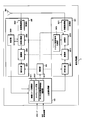
- FIG. 4 is a schematic block diagram showing the configuration of the terminal device 1 of the present embodiment.
- the terminal device 1 includes an upper layer processing unit 101, a control unit 103, a receiving unit 105, a transmitting unit 107, and a transmission / reception antenna 109.
- the upper layer processing unit 101 includes a radio resource control unit 1011, a scheduling information interpretation unit 1013, and a channel state information (CSI) report control unit 1015.
- the reception unit 105 includes a decoding unit 1051, a demodulation unit 1053, a demultiplexing unit 1055, a wireless reception unit 1057, and a measurement unit 1059.
- the transmission unit 107 includes an encoding unit 1071, a modulation unit 1073, a multiplexing unit 1075, a radio transmission unit 1077, and an uplink reference signal generation unit 1079.
- the upper layer processing unit 101 outputs uplink data (transport block) generated by a user operation or the like to the transmission unit 107.
- the upper layer processing unit 101 includes a medium access control (MAC: Medium Access Control) layer, a packet data integration protocol (Packet Data Convergence Protocol: PDCP) layer, a radio link control (Radio Link Control: RLC) layer, and radio resource control. Process the (Radio Resource Control: RRC) layer.
- MAC Medium Access Control
- PDCP Packet Data Convergence Protocol
- RLC Radio Link Control
- RRC Radio Resource Control
- the radio resource control unit 1011 included in the upper layer processing unit 101 manages various setting information of the own device. Also, the radio resource control unit 1011 generates information arranged in each uplink channel and outputs the information to the transmission unit 107.
- the scheduling information interpretation unit 1013 provided in the upper layer processing unit 101 interprets the DCI format (scheduling information) received via the reception unit 105, and based on the interpretation result of the DCI format, the reception unit 105 and the transmission unit Control information is generated in order to perform the control of 107 and output to the control unit 103.
- the CSI report control unit 1015 instructs the measurement unit 1059 to derive channel state information (RI / PMI / CQI) related to the CSI reference resource.
- the CSI report control unit 1015 instructs the transmission unit 107 to transmit RI / PMI / CQI.
- the CSI report control unit 1015 sets a setting used when the measurement unit 1059 calculates the CQI.
- the control unit 103 generates a control signal for controlling the receiving unit 105 and the transmitting unit 107 based on the control information from the higher layer processing unit 101. Control unit 103 outputs the generated control signal to receiving unit 105 and transmitting unit 107 to control receiving unit 105 and transmitting unit 107.
- the receiving unit 105 separates, demodulates, and decodes the received signal received from the base station apparatus 3 via the transmission / reception antenna 109 according to the control signal input from the control unit 103, and sends the decoded information to the upper layer processing unit 101. Output.
- the radio reception unit 1057 converts the downlink signal received via the transmission / reception antenna 109 into an intermediate frequency (down-conversion: down covert), removes unnecessary frequency components, and maintains the signal level appropriately. Then, the amplification level is controlled, quadrature demodulation is performed based on the in-phase component and the quadrature component of the received signal, and the quadrature demodulated analog signal is converted into a digital signal.
- the radio reception unit 1057 removes a portion corresponding to a guard interval (Guard Interval: GI) from the converted digital signal, and performs a fast Fourier transform (FFT Fourier Transform: FFT) on the signal from which the guard interval has been removed. Extract the region signal.
- GI Guard Interval
- FFT fast Fourier transform
- the demultiplexing unit 1055 separates the extracted signals into PHICH, PDCCH, EPDCCH, PDSCH, and downlink reference signals. Further, demultiplexing section 1055 compensates the propagation path of PHICH, PDCCH, EPDCCH, and PDSCH from the estimated value of the propagation path input from measurement section 1059. Also, the demultiplexing unit 1055 outputs the separated downlink reference signal to the measurement unit 1059.
- the demodulating unit 1053 multiplies the PHICH by a corresponding code and synthesizes it, demodulates the synthesized signal using a BPSK (Binary Phase Shift Shift Keying) modulation method, and outputs the demodulated signal to the decoding unit 1051.
- Decoding section 1051 decodes the PHICH addressed to the own apparatus, and outputs the decoded HARQ indicator to higher layer processing section 101.
- Demodulation section 1053 performs QPSK modulation demodulation on PDCCH and / or EPDCCH, and outputs the result to decoding section 1051.
- Decoding section 1051 attempts to decode PDCCH and / or EPDCCH, and outputs the decoded downlink control information and the RNTI corresponding to the downlink control information to higher layer processing section 101 when the decoding is successful.
- the demodulation unit 1053 demodulates the modulation scheme notified by the downlink grant such as QPSK (Quadrature Shift Keying), 16QAM (Quadrature Amplitude Modulation), 64QAM, and the like to the decoding unit 1051.
- the decoding unit 1051 performs decoding based on the information regarding the coding rate notified by the downlink control information, and outputs the decoded downlink data (transport block) to the higher layer processing unit 101.
- the measurement unit 1059 performs downlink path loss measurement, channel measurement, and / or interference measurement from the downlink reference signal input from the demultiplexing unit 1055.
- the measurement unit 1059 outputs the channel state information calculated based on the measurement result and the measurement result to the upper layer processing unit 101. Also, measurement section 1059 calculates an estimated value of the downlink propagation path from the downlink reference signal, and outputs it to demultiplexing section 1055.
- the transmission unit 107 generates an uplink reference signal according to the control signal input from the control unit 103, encodes and modulates the uplink data (transport block) input from the higher layer processing unit 101, PUCCH, The PUSCH and the generated uplink reference signal are multiplexed and transmitted to the base station apparatus 3 via the transmission / reception antenna 109.
- the encoding unit 1071 encodes the uplink control information and the uplink data input from the higher layer processing unit 101.
- the modulation unit 1073 modulates the coded bits input from the coding unit 1071 using a modulation scheme such as BPSK, QPSK, 16QAM, or 64QAM.
- the uplink reference signal generation unit 1079 is a physical cell identifier for identifying the base station device 3 (referred to as physical cell ⁇ ⁇ identity: ⁇ ⁇ ⁇ PCI, Cell ⁇ ID, etc.), a bandwidth for arranging the uplink reference signal, and an uplink grant.
- a sequence determined by a predetermined rule is generated based on the notified cyclic shift, the value of a parameter for generating the DMRS sequence, and the like.
- Multiplexer 1075 determines the number of PUSCH layers to be spatially multiplexed based on information used for PUSCH scheduling, and uses multiple SMs (Multiple Input Multiple Output Spatial Multiplexing) to transmit multiple PUSCHs. Are mapped to a plurality of layers, and precoding is performed on these layers.
- SMs Multiple Input Multiple Output Spatial Multiplexing
- the multiplexing unit 1075 performs discrete Fourier transform (Discrete-Fourier-Transform: DFT) on the modulation symbols of the PUSCH according to the control signal input from the control unit 103. Also, multiplexing section 1075 multiplexes the PUCCH and PUSCH signals and the generated uplink reference signal for each transmission antenna port. That is, multiplexing section 1075 arranges the PUCCH and PUSCH signals and the generated uplink reference signal in the resource element for each transmission antenna port.
- DFT discrete Fourier transform
- Radio transmission section 1077 performs inverse fast Fourier transform (inverse Fast Transform: IFFT) on the multiplexed signal, performs SC-FDMA modulation, and adds a guard interval to the SC-FDMA-modulated SC-FDMA symbol
- IFFT inverse Fast Transform
- a baseband digital signal converting the baseband digital signal to an analog signal, generating an in-phase component and a quadrature component of an intermediate frequency from the analog signal, removing an extra frequency component for the intermediate frequency band,
- the intermediate frequency signal is converted to a high frequency signal (up-conversion: up convert), an extra frequency component is removed, the power is amplified, and output to the transmission / reception antenna 109 for transmission.
- FIG. 5 is a schematic block diagram showing the configuration of the base station apparatus 3 of the present embodiment.
- the base station apparatus 3 includes an upper layer processing unit 301, a control unit 303, a reception unit 305, a transmission unit 307, and a transmission / reception antenna 309.
- the upper layer processing unit 301 includes a radio resource control unit 3011, a scheduling unit 3013, and a CSI report control unit 3015.
- the reception unit 305 includes a decoding unit 3051, a demodulation unit 3053, a demultiplexing unit 3055, a wireless reception unit 3057, and a measurement unit 3059.
- the transmission unit 307 includes an encoding unit 3071, a modulation unit 3073, a multiplexing unit 3075, a radio transmission unit 3077, and a downlink reference signal generation unit 3079.
- the upper layer processing unit 301 includes a medium access control (MAC: Medium Access Control) layer, a packet data integration protocol (Packet Data Convergence Protocol: PDCP) layer, a radio link control (Radio Link Control: RLC) layer, a radio resource control (Radio). Resource (Control: RRC) layer processing. Further, upper layer processing section 301 generates control information for controlling receiving section 305 and transmitting section 307 and outputs the control information to control section 303.
- MAC Medium Access Control
- PDCP Packet Data Convergence Protocol
- RLC Radio Link Control
- Radio Radio Resource
- the radio resource control unit 3011 included in the higher layer processing unit 301 generates downlink data (transport block), system information, RRC message, MAC CE (Control Element), etc. arranged in the downlink PDSCH, or higher level. Obtained from the node and output to the transmission unit 307.
- the radio resource control unit 3011 manages various setting information of each terminal device 1.
- the scheduling unit 3013 included in the higher layer processing unit 301 uses the received channel state information and the estimated channel value and channel quality input from the measurement unit 3059 to allocate frequencies and subframes for allocating physical channels (PDSCH and PUSCH).
- the coding rate and modulation scheme of physical channels (PDSCH and PUSCH), transmission power, and the like are determined.
- scheduling section 3013 Based on the scheduling result, scheduling section 3013 generates control information for controlling receiving section 305 and transmitting section 307 and outputs the control information to control section 303.
- the scheduling unit 3013 generates information (for example, DCI format) used for scheduling physical channels (PDSCH and PUSCH) based on the scheduling result.
- the CSI report control unit 3015 provided in the higher layer processing unit 301 controls the CSI report of the terminal device 1.
- the CSI report control unit 3015 transmits, to the terminal device 1 via the transmission unit 307, information indicating various settings assumed for the terminal device 1 to derive RI / PMI / CQI in the CSI reference resource.
- the control unit 303 generates a control signal for controlling the reception unit 305 and the transmission unit 307 based on the control information from the higher layer processing unit 301.
- the control unit 303 outputs the generated control signal to the reception unit 305 and the transmission unit 307 and controls the reception unit 305 and the transmission unit 307.
- the receiving unit 305 separates, demodulates and decodes the received signal received from the terminal device 1 via the transmission / reception antenna 309 according to the control signal input from the control unit 303, and outputs the decoded information to the higher layer processing unit 301.
- the radio reception unit 3057 converts an uplink signal received via the transmission / reception antenna 309 into an intermediate frequency (down-conversion: down covert), removes unnecessary frequency components, and appropriately maintains the signal level. In this way, the amplification level is controlled, and based on the in-phase and quadrature components of the received signal, quadrature demodulation is performed, and the quadrature demodulated analog signal is converted into a digital signal.
- the wireless receiver 3057 removes a portion corresponding to a guard interval (Guard Interval: GI) from the converted digital signal.
- the radio reception unit 3057 performs fast Fourier transform (FFT) on the signal from which the guard interval is removed, extracts a frequency domain signal, and outputs the signal to the demultiplexing unit 3055.
- FFT fast Fourier transform
- the demultiplexing unit 1055 demultiplexes the signal input from the radio receiving unit 3057 into signals such as PUCCH, PUSCH, and uplink reference signal. Note that this separation is performed based on radio resource allocation information included in the uplink grant that is determined in advance by the radio resource control unit 3011 by the base station device 3 and notified to each terminal device 1. Further, demultiplexing section 3055 compensates for the propagation paths of PUCCH and PUSCH based on the propagation path estimation value input from measurement section 3059. Also, the demultiplexing unit 3055 outputs the separated uplink reference signal to the measurement unit 3059.
- the demodulator 3053 performs inverse discrete Fourier transform (Inverse Discrete Fourier Transform: IDFT) on the PUSCH, acquires modulation symbols, and performs BPSK (Binary Shift Keying), QPSK, 16QAM, and PUCCH and PUSCH modulation symbols respectively.
- IDFT inverse discrete Fourier transform
- the received signal is demodulated using a predetermined modulation scheme such as 64QAM, or the modulation method notified by the own device to each terminal device 1 in advance using an uplink grant.
- the demodulator 3053 uses the MIMO SM based on the number of spatially multiplexed sequences notified in advance to each terminal device 1 using an uplink grant and information indicating precoding performed on the sequences.
- a plurality of uplink data modulation symbols transmitted on the PUSCH are separated.
- the decoding unit 3051 encodes the demodulated PUCCH and PUSCH encoding bits in a predetermined encoding scheme, or a coding rate at which the device itself notifies the terminal device 1 in advance with an uplink grant. And the decoded uplink data and the uplink control information are output to the upper layer processing unit 101.
- decoding section 3051 performs decoding using the encoded bits held in the HARQ buffer input from higher layer processing section 301 and the demodulated encoded bits.
- the measurement unit 309 measures the channel estimation value, channel quality, and the like from the uplink reference signal input from the demultiplexing unit 3055 and outputs the measured values to the demultiplexing unit 3055 and the upper layer processing unit 301.
- the transmission unit 307 generates a downlink reference signal according to the control signal input from the control unit 303, encodes and modulates the HARQ indicator, downlink control information, and downlink data input from the higher layer processing unit 301. Then, the PHICH, PDCCH, EPDCCH, PDSCH, and downlink reference signal are multiplexed, and the signal is transmitted to the terminal device 1 via the transmission / reception antenna 309.
- the encoding unit 3071 encodes the HARQ indicator, the downlink control information, and the downlink data input from the higher layer processing unit 301.
- the modulation unit 3073 modulates the coded bits input from the coding unit 3071 using a modulation scheme such as BPSK, QPSK, 16QAM, or 64QAM.
- the downlink reference signal generation unit 3079 generates a known sequence as a downlink reference signal, which is obtained by a predetermined rule based on a physical cell identifier (PCI) for identifying the base station apparatus 3 and the like. To do.
- PCI physical cell identifier
- the multiplexing unit 3075 maps one or more downlink data transmitted on one PUSCH to one or more layers according to the number of spatially multiplexed PDSCH layers, and the one or more layers Precoding the layer.
- the multiplexing unit 375 multiplexes the downlink physical channel signal and the downlink reference signal for each transmission antenna port.
- the multiplexing unit 375 arranges the downlink physical channel signal and the downlink reference signal in the resource element for each transmission antenna port.
- the wireless transmission unit 3077 performs inverse fast Fourier transform (Inverse Fast Fourier Transform: IFFT) on the multiplexed modulation symbols and the like, performs modulation in the OFDM scheme, adds a guard interval to the OFDM symbol that has been OFDM-modulated, and baseband
- IFFT inverse Fast Fourier Transform
- the baseband digital signal is converted to an analog signal, the in-phase and quadrature components of the intermediate frequency are generated from the analog signal, the extra frequency components for the intermediate frequency band are removed, and the intermediate-frequency signal is generated. Is converted to a high-frequency signal (up-conversion: up convert), an extra frequency component is removed, power is amplified, and output to the transmission / reception antenna 309 for transmission.
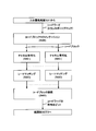
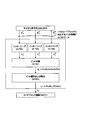
- FIG. 6 is a diagram illustrating an example of processing in the encoding unit 3071 of the present embodiment.
- the encoding unit 3071 may apply the process of FIG. 6 to each transport block.
- One transport block is mapped to one codeword. That is, encoding a transport block is the same as encoding a codeword.
- the encoding unit 3071 adds a corresponding CRC parity bit to one codeword input from the higher layer processing unit 301, and then divides the codeword into one or a plurality of code blocks (S600). A corresponding CRC parity bit may be added to each code block.
- Each of one or a plurality of code blocks is encoded (for example, turbo encoding or convolutional encoding) (S601). Rate matching is applied to each coded bit sequence of the code block (S602). A sequence of coded bits of a codeword is obtained by concatenating one or more code blocks to which rate matching has been applied (S603). The sequence of coded bits of the code word is output to modulation section 3073.
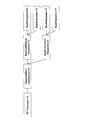
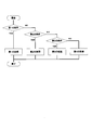
- FIG. 7 is a diagram illustrating an example of processing in the multiplexing unit 3075 of the present embodiment.
- the multiplexing unit 3075 maps the complex value symbols of the first codeword and the complex value symbols of the second codeword input from the modulation unit 3073 to one or more layers (S700). Note that only the complex value symbol of the first code word may be input from the modulation unit 3073. Note that the number of input code words is the same as or smaller than the number of layers.
- Precoding is applied to the complex value symbols mapped to the layer (S701). Precoding generates as many sequences of complex-valued symbols as there are corresponding transmit antenna ports. Note that the number of layers is the same as or smaller than the number of transmit antenna ports corresponding to PDSCH transmission. For each transmit antenna port corresponding to PDSCH transmission, a complex value symbol to which precoding is applied is mapped to a resource element (S702).
- the terminal device 1 sets a transmission mode for PDSCH transmission based on the information received from the base station device 3.
- the terminal device 1 is set by the upper layer to receive the PDSCH data transmission signaled through the PDCCH according to the transmission mode.
- the terminal device 1 selects a DCI format to be monitored according to the transmission mode. Also, the terminal device 1 identifies the PDSCH transmission method corresponding to the DCI format according to the transmission mode and the received DCI format.
- FIG. 8 is a diagram illustrating an example of correspondence between the transmission mode, the DCI format, and the PDSCH transmission method in the present embodiment.
- the column of P800 in FIG. 8 indicates the transmission mode.
- the column of P801 in FIG. 8 shows the DCI format.
- the column of P802 in FIG. 8 indicates the PDSCH transmission scheme corresponding to the PDCCH and the number of layers supported by the PDSCH transmission scheme.
- the PDSCH transmission method corresponding to the PDCCH is closed loop spatial multiplexing (up to 4 layers), Or transmission diversity (one layer).
- the information included in the DCI format 2 indicates either closed-loop spatial multiplexing or transmission diversity.
- Information included in DCI format 2 indicates the number of layers that are spatially multiplexed.
- the terminal device 1 transmits capability information (UECapabilityInformation) to the base station device 3.
- the base station device 3 sets the terminal device 1 according to the capability information and schedules the terminal device 1.
- the capability information may include a plurality of capability parameters (UE-radio-access-capability-parameters).
- One capability parameter corresponds to one function or a group of functions.
- One capability parameter may indicate whether a corresponding function or group of corresponding functions has been successfully tested.
- One capability parameter may indicate whether the terminal device 1 supports a corresponding function or a group of corresponding functions.
- the capability information is RRC layer information.
- the capability parameter is a parameter of the RRC layer.
- the capability information may include one or more capability parameters indicating the UE category.
- the capability information may include one capability parameter indicating a downlink UE category.
- the downlink UE category is defined separately from the UE category.
- the UE category and the downlink UE category correspond to the total number of DL-SCH soft channel bits and the maximum number of supported layers for spatial multiplexing in the downlink.
- the total number of DL-SCH soft channel bits is the total number of soft channel bits available for DL-SCH HARQ processing.
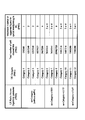
- FIG. 9 is a diagram illustrating an example of a UE category in the present embodiment.
- the column of P900 in FIG. 9 shows capability parameters indicating the UE category.
- the column of P901 in FIG. 9 shows the UE category indicated by the capability parameter.
- P902 in FIG. 9 indicates the total number of DL-SCH soft channel bits to which the UE category corresponds.
- P903 in FIG. 9 indicates the maximum number of layers supported for spatial multiplexing in the downlink to which the UE category corresponds.
- the capability parameter ue-Category (without suffix) indicates any one of UE categories 1 to 5.
- the capability parameter ue-Category-v1020 indicates any one of UE categories 6 to 8.
- the capability parameter ue-Category-v1170 indicates any one of UE categories 9 and 10.
- the capability parameter ue-Category-v11a0 indicates one of the UE categories 11 and 12.
- FIG. 10 is a diagram illustrating an example of a downlink UE category in the present embodiment.
- the column of P1000 in FIG. 10 shows capability parameters indicating downlink UE categories.
- the P1001 column in FIG. 10 indicates the downlink UE category indicated by the capability parameter.
- P1002 in FIG. 10 indicates the total number of DL-SCH soft channel bits to which the downlink UE category corresponds.
- P1003 in FIG. 10 indicates the maximum number of layers supported for spatial multiplexing in the downlink to which the downlink UE category corresponds.
- the capability parameter ue-CategoryDL-r12 indicates any one of the downlink UE categories 0, 6, 7, 9, 10, 11, 12, 13, and 14.
- FIG. 11 is a diagram illustrating an example of a combination of categories indicated by a plurality of capability parameters according to the present embodiment.
- the capability parameter ue-CategoryDL-r12 indicates the downlink UE category 9
- the capability parameter ue-Category-v1020 indicates the UE category 6
- the capability parameter ue-Category (without suffix) is UE. It expresses showing Category 4.
- the capability information may include a carrier aggregation supported by the terminal device 1 and a capability parameter supportedBandCombination indicating MIMO.
- the capability parameter supportedBandCombination indicates one or more band combinations.
- the one band combination includes one or more bands.
- the one band includes one or more combinations of supported bandwidth classes and MIMO capabilities for the downlink. That is, the terminal device 1 provides the base station device 3 with the MIMO capability for the downlink for each bandwidth class for each band combination specified in the capability parameter supportedBandCombination.
- the MIMO capability for the downlink indicates the maximum number of layers supported by the terminal device 1 and is applied to all component carriers (cells) corresponding to the bandwidth class.
- the bandwidth class corresponds to the aggregated transmission bandwidth setting and the maximum number of component carriers supported by the terminal device 1 for the bandwidth class.
- the aggregated transmission bandwidth setting is defined by the total number of resource blocks included in the component carriers aggregated in the corresponding band.
- a plurality of component carriers corresponding to the bandwidth class are continuous in the frequency domain. There may be a guard band of 300 kHz or less between consecutive component carriers in the frequency domain.
- FIG. 12 is a diagram illustrating an example of a bandwidth class according to the present embodiment.
- the bandwidth class is C
- the aggregated transmission bandwidth setting is greater than 25, the same as or smaller than 100
- the maximum number of component carriers is 2.
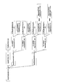
- FIGS. 13 and 14 are diagrams illustrating an example of the configuration of the capability parameter supportedBandCombination in the present embodiment.
- the capability parameter supportedBandCombination is included in the capability parameter RF-Parameters-r10.
- the capability parameter supportedBandCombination includes one or more parameters BandCombinationParameters-r10.
- the capability parameter supportedBandCombination indicates a band combination.
- the parameter BandCombinationParameters-r10 includes one or more parameters BandParameters-r10.
- the parameter BandParameters-r10 indicates one band.
- the parameter FreqBandIndicator included in the parameter BandParameters-r10 indicates the frequency of the corresponding band.
- the parameter bandParametersUL-r10 included in the parameter BandParameters-r10 includes one or more parameters CA-MIMO-ParametersUL-r10.
- the parameter CA-MIMO-ParametersUL-r10 includes a parameter ca-BandwidthClassUL-r10 and a parameter supportedMIMO-CapabilityUL-r10.
- the parameter ca-BandwidthClassUL-r10 indicates the bandwidth class for the uplink in the corresponding band.
- the parameter supportedMIMO-CapabilityUL-r10 indicates the MIMO capability for the uplink in the corresponding band (the maximum number of layers supported by the terminal device 1). That is, the parameter ca-BandwidthClassUL-r10 indicates one combination of the bandwidth class and the MIMO capability for the uplink.
- the parameter bandParametersDL-r10 included in the parameter BandParameters-r10 includes one or more parameters CA-MIMO-ParametersDL-r10.
- the parameter CA-MIMO-ParametersDL-r10 includes a parameter ca-BandwidthClassDL-r10 and a parameter supportedMIMO-CapabilityDL-r10.
- the parameter ca-BandwidthClassDL-r10 indicates the bandwidth class for the downlink in the corresponding band.
- the parameter supportedMIMO-CapabilityDL-r10 indicates the MIMO capability for the downlink in the corresponding band (the maximum number of layers supported by the terminal device 1). That is, the parameter ca-BandwidthClassDL-r10 indicates one combination of the bandwidth class and the MIMO capability for the downlink.
- the capability parameter supportedBandCombination may indicate the MIMO capability (the maximum number of layers supported by the terminal device 1) without carrier aggregation.
- the terminal device 1 For each of the bandwidth classes for each band combination specified in the capability parameter supportedBandCombination, the terminal device 1 further indicates the maximum number of layers supported by the terminal device 1, and the bandwidth class
- the base station apparatus is provided with a MIMO capability (parameter supported MIMO-Capability DL-v10xx) applied to any one of the downlink component carriers corresponding to.
- the parameter supportedMIMO-CapabilityDL-v10xx For each bandwidth class for each band combination specified in the capability parameter supportedBandCombination, the parameter supportedMIMO-CapabilityDL-v10xx may be included in the capability information.
- the terminal device 1 corresponds to the bandwidth class to the base station device 3.
- MIMO capability (parameter supportedMIMO-CapabilityDL-r10) applied to all downlink component carriers to be applied to the downlink component carrier corresponding to the bandwidth class (parameter supportedMIMO- CapabilityDL-v10xx). Note that the parameter supportedMIMO-CapabilityDL-v10xx may not be included in the capability parameter supportedBandCombination.
- FIG. 15 is a diagram illustrating an example of a combination of a bandwidth class and a MIMO capability in the present embodiment.
- the terminal apparatus 1 may provide the base station apparatus 3 with the four combinations shown in FIG. 15 for one band in one combination of bands specified in the capability parameter supportedBandCombination.
- the bandwidth class is B
- the parameter supportedMIMO-CapabilityDL-r10 indicates 2
- the parameter supportedMIMO-CapabilityDL-v10xx indicates ⁇ 4, 2 ⁇ .
- the base station apparatus 3 that cannot decode the parameter supportedMIMO-CapabilityDL-v10xx has a maximum number of 2 layers supported in each of two downlink component carriers (two cells) set in the corresponding band. Judge that there is.
- the base station apparatus 3 capable of decoding the parameter supportedMIMO-CapabilityDL-v10xx has a maximum number of 4 layers supported in one of two downlink component carriers (two cells) set in the corresponding band. It is determined that the maximum number of layers supported in the other of the two downlink component carriers is two.
- the base station apparatus 3 may control which of the two downlink component carriers is applied with PDSCH (DL-SCH) transmission using up to four layers.
- the base station apparatus 3 applies only to the first downlink component carrier of the two downlink component carriers, and transmits the parameter LayersCount-v10xx indicating the maximum number of layers to the terminal apparatus 1. May be.
- the base station apparatus 3 is applied only to one second downlink component carrier of the two downlink component carriers, and transmits a parameter LayersCount-v10xx indicating the maximum number of layers to the terminal apparatus 1. May be.
- the parameter LayersCount-v10xx is a parameter of the RRC layer.
- the base station device 3 is a parameter LayersCount-v10xx for one first downlink component carrier of the two downlink component carriers, a parameter LayersCount-v10xx indicating 4, and The parameter LayersCount-v10xx for one second downlink component carrier of the two downlink component carriers, and the parameter LayersCount-v10xx indicating 2 may be transmitted to the terminal device 1.
- the terminal device 1 when the terminal device 1 receives / sets the parameter LayersCount-v10xx for one first downlink component carrier of the two downlink component carriers, the terminal device 1 It may be determined that up to four layers indicated by the parameter LayersCount-v10xx are applied to PDSCH (DL-SCH) transmission in the first downlink component carrier of one of the carriers.
- PDSCH DL-SCH
- the terminal device 1 when the terminal device 1 has not received / set the parameter LayersCount-v10xx for one second downlink component carrier of the two downlink component carriers, the terminal device 1 It may be determined that up to two layers indicated by the parameter supported MIMO-Capability DL-r10 are applied to PDSCH (DL-SCH) transmission in the second downlink component carrier of one of the carriers.
- DL-SCH PDSCH
- the terminal device 1 when the capability information does not include the parameter supportedMIMO-CapabilityDL-r10 and the parameter supportedMIMO-CapabilityDL-v10xx, the terminal device 1 has the first one of the two downlink component carriers.
- PDSCH DL-SCH
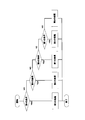
- FIG. 16 is a diagram illustrating an example of a sequence chart between the terminal device 1 and the base station device 3 in the present embodiment.
- the base station device 3 transmits a UECapabilityEnquiry message to the terminal device 1 (S160).
- the UECapabilityEnquiry message is an RRC layer message.
- the UECapabilityEnquiry message is used to request transmission of capability information (UECapabilityInformation).
- the terminal device 1 transmits capability information (UECapabilityInformation) to the base station device 3 (S161).
- the base station apparatus 3 determines the carrier aggregation for the terminal apparatus 1, the transmission mode for PDSCH transmission, and / or the MIMO setting for PDSCH transmission according to the received capability information (UECapabilityInformation) (S162).
- the base station device 3 transmits an RRCConnectionReconfiguration message to the terminal device 1 (S163).
- the RRCConnectionReconfiguration message transmits RRC layer information for the setting determined in S161.
- the RRCConnectionReconfiguration message is a command for correcting the RRC connection.
- the RRCConnectionReconfiguration message may include a parameter LayersCount-v10xx.
- the terminal device 1 corrects / reconfigures the RRC connection according to the received RRCConnectionReconfiguration message. That is, the terminal device 1 corrects / reconfigures the carrier aggregation, the transmission mode related to PDSCH transmission, and / or the MIMO related to PDSCH transmission according to the received RRCConnectionReconfiguration message.
- the terminal device 1 transmits an RRCConnectionReconfigurationComplete message to the base station device 3 after correcting the RRC connection according to the received RRCConnectionReconfiguration message.
- the RRCConnectionReconfigurationComplete message is an RRC layer message.
- the RRCConnectionReconfigurationComplete message is used for confirmation of normal completion (successful completion) of RRC connection reconfiguration.
- the terminal device 1 and the base station device 3 specify the bit width of the RI based on the setting determined in S162 and / or capability information (UECapabilityInformation) (S165).
- the terminal device 1 transmits the RI having the bit width determined in S165 to the base station device 3 using PUCCH or PUSCH.
- the base station apparatus 3 performs RI reception processing (demultiplexing, demodulation, and / or decoding) by assuming the RI having the bit width determined in S165.
- the bit width of RI is given for each corresponding downlink component carrier (cell).
- the bit widths of RI corresponding to different downlink component carriers may be different.
- the bit width of RI is “1”.
- the bit width of the RI is “2”.
- the RI bit width is “3”.
- the terminal apparatus 1 and the base station apparatus 3 use a soft buffer for a code block of a transport block (codeword) transmitted on the PDSCH based on the setting determined in S162 and / or capability information (UECapabilityInformation)
- the size and rate matching for the code block are specified (S167).
- the base station apparatus 3 encodes the transport block according to the rate matching with respect to the code block of the transport block identified in S167, and transmits the encoded transport block to the terminal apparatus 1 by PDSCH. (S168).
- the terminal device 1 performs reception processing (decoding) of the transport block in accordance with rate matching with respect to the code block of the transport block specified in S167.
- the terminal device 1 When the terminal device 1 fails to decode the code block of the transport block, the terminal device 1 stores a part or all of the soft channel bits of the code block (S169). Which of the soft channel bits of the code block is stored is given by referring to the soft buffer size for the code block of the transport block identified in S167. The stored soft channel bits are used for HARQ processing for the code block. The stored soft channel bits may be combined with the retransmitted soft channel bits.
- the terminal device 1 uses the PDSCH (Physical Downlink Shared CHannel in the first downlink component carrier corresponding to the first bandwidth class of the first band in the first band combination. ) RI (Rank Indicator) corresponding to the transmission and corresponding to the number of effective layers (useful layers), and transmitting the RI determined by the terminal device, and receiving the PDSCH A receiving unit 105.
- the transmission unit 107 includes first information (ue-Category (without suffix)), second information (ca-BandwidthClassDL-r10), third information (supportedMIMO-CapabilityDL-r10), and / or The capability information (UECapabilityInformation) including the fourth information (supportedMIMO-CapabilityDL-v10xx) is transmitted.
- the reception unit 105 includes fifth information (LayersCount-v10xx) for the first downlink component carrier corresponding to the first bandwidth class of the first band in the first band combination.
- the first information (ue-Category (without suffix)) indicates a UE category corresponding to the first maximum number of the layers supported by the terminal apparatus in the downlink.
- the second information (ca-BandwidthClassDL-r10) is the first bandwidth class for the first band in the first band combination, and is a downlink supported by the terminal apparatus. The first bandwidth class corresponding to the number of component carriers is indicated.
- the third information (supportedMIMO-CapabilityDL-r10) includes one or more downlink component carriers corresponding to the first bandwidth class of the first band in the first band combination.
- the second maximum number of layers applied to all and supported by the terminal device in the downlink is indicated.
- the fourth information (supported MIMO-Capability DL-v10xx) is the one or more downlink component carriers corresponding to the first bandwidth class of the first band in the first band combination.
- the third maximum number of the layers applied to any one of the above and supported by the terminal apparatus in the downlink is shown.
- the fifth information (LayersCount-v10xx) indicates the fourth maximum number of the layers.
- the fifth maximum number of layers assumed for the determination of the bit width for the RI corresponds to the first bandwidth class of the first band in the first band combination.
- the third information It is given by referring to any one of the second maximum number of layers and the fourth maximum number of layers indicated by the fifth information.
- the bit width for the RI is given by referring to the fifth maximum number of layers.
- the fifth information (LayersCount for the first downlink component carrier corresponding to the first bandwidth class of the first band in the first band combination) -v10xx) is not set, the fifth maximum number of layers assumed for the determination of the bit width for the RI is the first maximum number of layers and the first number of layers. Given by referring to any one of the maximum number of two.
- the fifth information (LayersCount-v10xx) for the first downlink component carrier corresponding to the first bandwidth class of the first band in the first band combination is set.
- the fifth maximum number of layers envisaged for determination of the bit width for the RI is given by referring to the fourth maximum number of layers.
- the fifth information (LayersCount for the first downlink component carrier corresponding to the first bandwidth class of the first band in the first band combination) -v10xx) is set, and the first transmission mode for the PDSCH transmission (eg, transmission mode 9) is set for the first downlink component carrier, for the RI
- the fifth maximum number of layers envisaged for bit width determination is: (i) the number of configured first ports, and (ii) the minimum of the third maximum number of layers Depending on the thing.
- the first port is a transmission antenna port for CSI-RS (Chanel State Information-Reference Signal).
- the fifth information (LayersCount for the first downlink component carrier corresponding to the first bandwidth class of the first band in the first band combination) -v10xx) is set and a second transmission mode (eg, transmission mode 4) for the PDSCH transmission is set for the first downlink component carrier,
- the fifth maximum number of the layers envisaged for bit width determination is the smallest of (i) the number of second ports and (ii) the third maximum number of layers. Will be decided accordingly.
- the second port is a transmission antenna port for PBCH (Physical Broadcast CHannel).
- the fifth information for the first downlink component carrier corresponding to the first bandwidth class of the first band in the first band combination is set, and the first If the second transmission mode for the PDSCH transmission is set for the downlink component carrier of the first, the fifth maximum number of the layers assumed for the determination of the bit width for the RI is at least It is determined according to the third maximum number of the layers indicated by the fifth information.
- the fifth information (LayersCount for the first downlink component carrier corresponding to the first bandwidth class of the first band in the first band combination) -v10xx) is not set, a first transmission mode (eg, transmission mode 9) for the PDSCH transmission is set for the first downlink component carrier, and the capability information (
- the third information (supportedMIMO-CapabilityDL-r10) is included in UECapabilityInformation)
- the fifth maximum number of the layers assumed for the determination of the bit width for the RI is (i) Determined according to the number of configured first ports and (ii) the minimum of the second maximum number of the layers indicated by the third information .
- the first port is a CSI-RS (Chanel State This is a transmit antenna port for Information-Reference Signal.
- the fifth information (LayersCount for the first downlink component carrier corresponding to the first bandwidth class of the first band in the first band combination) -v10xx) is not set, a first transmission mode (eg, transmission mode 9) for the PDSCH transmission is set for the first downlink component carrier, and the capability information ( If the third information (supportedMIMO-CapabilityDL-r10) is not included in UECapabilityInformation), the fifth maximum number of the layers assumed for determining the bit width for the RI is (i) Determined according to the set number of first ports and (ii) the smallest of the first maximum numbers of the layers corresponding to the first informationHere, the first port is a transmission antenna port for CSI-RS (Chanel State Information-Reference Signal).
- CSI-RS Channel State Information-Reference Signal
- the fifth information (LayersCount for the first downlink component carrier corresponding to the first bandwidth class of the first band in the first band combination) -v10xx) is not set and the second transmission mode (eg, transmission mode 4) for the PDSCH transmission is set for the first downlink component carrier,
- the fifth maximum number of layers envisaged for the determination of bit width is (i) the number of second ports, and (ii) the first maximum of the layers corresponding to the first information. Determined according to the smallest of the numbers.
- the second port is a transmission antenna port for PBCH (Physical Broadcast CHannel).
- the transmission unit 107 transmits the RI using PUSCH (Physical-Uplink-Shared-CHannel).
- PUSCH Physical-Uplink-Shared-CHannel
- the base station apparatus 3 performs PDSCH (Physical Downlink Shared on the first downlink component carrier corresponding to the first bandwidth class of the first band in the first band combination).
- a receiving unit 305 that receives the RI determined by the terminal device, which is an RI (Rank Indicator) corresponding to the number of effective layers and corresponding to the number of effective layers.
- a transmission unit 307 that transmits the PDSCH to the terminal device.
- the receiving unit 305 includes first information (ue-Category (without suffix)), second information (ca-BandwidthClassDL-r10), third information (supportedMIMO-CapabilityDL-r10), and / or The capability information (UECapabilityInformation) including the fourth information (supportedMIMO-CapabilityDL-v10xx) is received from the terminal device.
- the transmission unit 307 includes fifth information (LayersCount-v10xx) for the first downlink component carrier corresponding to the first bandwidth class of the first band in the first band combination. Is transmitted to the terminal device.
- the first information (ue-Category (without suffix)) indicates a UE category corresponding to the first maximum number of the layers supported by the terminal apparatus in the downlink.
- the second information (ca-BandwidthClassDL-r10) is the first bandwidth class for the first band in the first band combination, and is a downlink supported by the terminal apparatus.
- the first bandwidth class corresponding to the number of component carriers is indicated.
- the third information (supportedMIMO-CapabilityDL-r10) includes one or more downlink component carriers corresponding to the first bandwidth class of the first band in the first band combination.
- the second maximum number of layers applied to all and supported by the terminal device in the downlink is indicated.
- the fourth information (supported MIMO-Capability DL-v10xx) is the one or more downlink component carriers corresponding to the first bandwidth class of the first band in the first band combination.
- the third maximum number of the layers applied to any one of the above and supported by the terminal apparatus in the downlink is shown.
- the fifth information (LayersCount-v10xx) indicates the fourth maximum number of the layers.
- the fifth maximum number of layers assumed for determining the bit width for the RI is the first bandwidth class corresponding to the first bandwidth class of the first band in the first band combination.
- the fifth information (LayersCount for the first downlink component carrier corresponding to the first bandwidth class of the first band in the first band combination) -v10xx) is not set for the terminal device, the fifth maximum number of layers assumed for the determination of the bit width for the RI is the first maximum number of layers, And by referring to any one of the second maximum number of layers.
- the fifth information (LayersCount-v10xx) for the first downlink component carrier corresponding to the first bandwidth class of the first band in the first band combination is transmitted to the terminal apparatus. If set for, the fifth maximum number of layers assumed for the determination of the bit width for the RI is given by referring to the fourth maximum number of layers.
- the fifth information (LayersCount) for the first downlink component carrier corresponding to the first bandwidth class of the first band in the first band combination -v10xx) is set for the terminal apparatus, and the first transmission mode (for example, transmission mode 9) related to the PDSCH transmission is set for the terminal apparatus for the first downlink component carrier.
- the fifth maximum number of layers assumed for the determination of the bit width for the RI is (i) the number of configured first ports, and (ii) Determined according to the smallest of the third maximum number of layers, wherein the first port is for CSI-RS (Chanel State Information Information Reference Signal) It is a signal antenna port.
- CSI-RS Channel State Information Information Reference Signal
- the fifth information (LayersCount) for the first downlink component carrier corresponding to the first bandwidth class of the first band in the first band combination -v10xx) is set for the terminal device, and the second transmission mode (for example, transmission mode 4) related to the PDSCH transmission is set for the terminal device for the first downlink component carrier.
- the fifth maximum number of layers envisaged for determining the bit width for the RI is (i) the number of second ports, and (ii) the layer's Determined according to the smallest of the third maximum numbers.
- the second port is a transmission antenna port for PBCH (Physical Broadcast CHannel).
- the fifth information for the first downlink component carrier corresponding to the first bandwidth class of the first band in the first band combination is set, and the first If the second transmission mode for the PDSCH transmission is set for the downlink component carrier of the first, the fifth maximum number of the layers assumed for the determination of the bit width for the RI is at least It is determined according to the third maximum number of the layers indicated by the fifth information.
- the fifth information (LayersCount for the first downlink component carrier corresponding to the first bandwidth class of the first band in the first band combination) -v10xx) is not set for the terminal device, and the first transmission mode (for example, transmission mode 9) for the PDSCH transmission is set for the terminal device for the first downlink component carrier.
- the third information (supportedMIMO-CapabilityDL-r10) is included in the capability information (UECapabilityInformation), it is assumed that the bit width for the RI is determined.
- the fifth maximum number of layers is (i) the number of configured first ports, and (ii) the second number of the layers indicated by the third information. The maximum number is determined according to the smallest of the of.
- the first port is a transmission antenna port for CSI-RS (Chanel State Information-Reference Signal).
- the fifth information (LayersCount for the first downlink component carrier corresponding to the first bandwidth class of the first band in the first band combination) -v10xx) is not set for the terminal device, and the first transmission mode (for example, transmission mode 9) for the PDSCH transmission is set for the terminal device for the first downlink component carrier.
- the third information (supportedMIMO-CapabilityDL-r10) is not included in the capability information (UECapabilityInformation), it is assumed that the bit width for the RI is determined.
- the fifth maximum number of layers is: (i) the number of configured first ports; and (ii) the first maximum number of layers corresponding to the first information. It is determined according to the smallest of a few.
- the first port is a transmission antenna port for CSI-RS (Chanel State Information-Reference Signal).
- the fifth information (LayersCount for the first downlink component carrier corresponding to the first bandwidth class of the first band in the first band combination) -v10xx) is not set for the terminal device, and the second transmission mode (for example, transmission mode 4) related to the PDSCH transmission is set for the terminal device for the first downlink component carrier.
- the fifth maximum number of layers envisioned for determining the bit width for the RI is (i) the number of second ports, and (ii) the first Is determined according to a minimum one of the first maximum numbers of the layers corresponding to the information.
- the second port is a transmission antenna port for PBCH (Physical Broadcast CHannel).
- the reception unit 305 receives the RI by PUSCH (Physical-Uplink-Shared-CHannel).
- the capability information includes the third information (supportedMIMO-CapabilityDL-r10).
- the capability information may not include the fourth information (supportedMIMO-CapabilityDL-v10xx).
- the terminal device 1 supports PDSCH (Physical Downlink Shared Shared CHannel) transmission in a downlink component carrier corresponding to the first band in the first band combination, and RI (Rank Indicator) corresponding to the number, and includes a transmitter 107 that transmits the RI determined by the terminal device, and a receiver 105 that receives the PDSCH.
- PDSCH Physical Downlink Shared Shared CHannel
- RI Rank Indicator
- the first band combination includes only the first band.
- the transmission mode 9 or 10 related to the PDSCH transmission is set in the terminal device.
- the transmission unit 107 includes the first information (ca-BandwidthClassDL-r10), the second information (supportedMIMO-CapabilityDL-r10), and the third information (ca-BandwidthClassDL- r10) and capability information (UECapabilityInformation) including the fourth information (supportedMIMO-CapabilityDL-r10) is transmitted.
- the first information (ca-BandwidthClassDL-r10) is a first bandwidth class of the first band in the first band combination, and is a downlink component supported by the terminal apparatus.
- the first bandwidth class indicating a first number of carriers is indicated.
- the second information (supported MIMO-Capability DL-r10) is the first number of downlink component carriers corresponding to the first bandwidth class of the first band in the first band combination.
- the third information (ca-BandwidthClassDL-r10) is a second bandwidth class of the first band in the first band combination, and is a downlink component supported by the terminal apparatus.
- Fig. 3 shows the second bandwidth class indicating a second number of carriers.
- the fourth information (supported MIMO-Capability DL-r10) is the second number of downlink component carriers corresponding to the second bandwidth class of the first band in the first band combination.
- the second maximum number of the layers applied to all of the above and supported by the terminal device in the downlink is the third maximum number of layers assumed for the determination of the bit width for the RI.
- the third maximum number of layers assumed for the determination of the bit width for the RI is the number of downlink component carriers set in the first band in the first band combination. Refers to either one of the first maximum number of layers and the second maximum number of layers based on whether is the first number or the second number Given by.
- the transmitting unit 107 transmits the RI using PUSCH (Physical-Uplink-Shared-CHannel).
- the bit width for the RI is the first maximum number of layers.
- the number of downlink component carriers set in the first band in the first band combination is the second number, it is assumed for determining the bit width for the RI.
- the third maximum number of layers is the second maximum number of layers.
- the capability information includes the third information (supportedMIMO-CapabilityDL-r10).
- the capability information may not include the fourth information (supportedMIMO-CapabilityDL-v10xx).
- the base station apparatus 3 corresponds to PDSCH (Physical Downlink Shared CHannel) transmission in a downlink component carrier corresponding to the first band in the first band combination, and the layer A receiving unit 305 that receives the RI determined by the terminal device from the terminal device, a transmitting unit 307 that transmits the PDSCH to the terminal device, Is provided.
- the first maximum number of the layers assumed for determining the bit width for the RI is a downlink set by the terminal apparatus in the first band in the first band combination. Based on the number of component carriers.
- the first band combination includes only the first band.
- the terminal device is set to transmission mode 9 or 10 related to the PDSCH transmission.
- the receiving unit 305 includes first information (ca-BandwidthClassDL-r10), second information (supportedMIMO-CapabilityDL-r10), and third information (ca-BandwidthClassDL- r10) and capability information (UECapabilityInformation) including the fourth information (supportedMIMO-CapabilityDL-r10) is received from the terminal device.
- the first information (ca-BandwidthClassDL-r10) is a first bandwidth class of the first band in the first band combination, and is a downlink component supported by the terminal apparatus.
- the first bandwidth class indicating a first number of carriers is indicated.
- the second information (supported MIMO-Capability DL-r10) is the first number of downlink component carriers corresponding to the first bandwidth class of the first band in the first band combination.
- the third information (ca-BandwidthClassDL-r10) is a second bandwidth class of the first band in the first band combination, and is a downlink component supported by the terminal apparatus.
- Fig. 3 shows the second bandwidth class indicating a second number of carriers.
- the fourth information (supported MIMO-Capability DL-r10) is the second number of downlink component carriers corresponding to the second bandwidth class of the first band in the first band combination.
- the second maximum number of the layers applied to all of the above and supported by the terminal device in the downlink is the third maximum number of layers assumed for the determination of the bit width for the RI.
- the third maximum number of layers assumed for the determination of the bit width for the RI is the number of downlink component carriers set in the first band in the first band combination. Refers to either one of the first maximum number of layers and the second maximum number of layers based on whether is the first number or the second number Given by.
- the receiving unit 305 receives the RI through a PUSCH (Physical-Uplink-Shared-CHannel).
- PUSCH Physical-Uplink-Shared-CHannel
- the bit width for the RI is the first maximum number of layers.
- the number of downlink component carriers set in the first band in the first band combination is the second number, it is assumed for determining the bit width for the RI.
- the third maximum number of layers is the second maximum number of layers.
- FIG. 17 is a diagram showing an example of rate matching in the present embodiment. Rate matching is executed in S602 of FIG. That is, rate matching is applied to the code block of the transport block.
- One rate matching includes three interleaving (S1700), one bit collection (S1701), one bit selection and pruning (S2002).
- three information bit streams (d ′ k , d ′′ k , d ′ ′′ k ) are input from channel coding (S601).
- Each of the three information bit streams (d ′ k , d ′′ k , d ′ ′′ k ) is interleaved according to the sub-block interleaver in interleaving (S1700).
- the number of subframe interleaver columns C subblock is 32.
- the number of rows of the sub-floc interleaver R subblock is the smallest integer that satisfies the following inequality (1).
- D is the number of each bit of the information bit stream (d ′ k , d ′′ k , d ′ ′′ k ).
- w k (virtual circular buffer) is obtained from the three output sequences (v ′ k , v ′′ k , v ′ ′′ k ).
- w k is given by the following equation (3).
- the number Kw of bits of w k is three times K ⁇ .
- FIG. 18 is a diagram illustrating an example of bit selection and removal according to the present embodiment.
- Rv idx in FIG. 18 is an RV (redundancy version) number for transmission of the corresponding transport block.
- the RV number is indicated by information included in the DCI format.
- N cb of Figure 18 is a soft buffer size for the corresponding code block is represented by the number of bits. N cb is given by the following equation (4).
- N IR is the soft buffer size for the corresponding transport block, and is represented by the number of bits. N IR is given by the following equation (5).
- K MIMO is the same as the maximum number of transport blocks that can be included in one PDSCH transmission received based on the transmission mode in which the terminal apparatus 1 is set.
- M DL_HARQ is the maximum number of downlink HARQ processes managed in parallel in one corresponding serving cell.
- M DL_HARQ may be 8.
- M DL_HARQ may correspond to uplink-downlink configuration.
- M limit is 8.
- K c is any one of 1, 3/2, 2, 3, and 5.
- the method for setting K c will be described after the method for setting N soft .
- N soft is the total number of soft channel bits corresponding to the UE category or the downlink UE category.
- N soft is given by any one of the ability parameter ue-Category (without suffix), the ability parameter ue-Category-v1020, the ability parameter ue-Category-v1170, and the ability parameter ue-CategoryDL-r12.
- the terminal device 1 When the parameter altCQI-Table-r12 is not set in the terminal device 1, the terminal device 1 is the first indicating the correspondence between the combination of the modulation scheme and the coding rate and the CQI for a single transport block transmitted on the PDSCH.
- the CQI is derived based on the following table.
- the terminal device 1 When the parameter altCQI-Table-r12 is set in the terminal device 1, the terminal device 1 is the second indicating the correspondence between the combination of the modulation scheme and the coding rate and the CQI for a single transport block transmitted on the PDSCH.
- the CQI is derived based on the following table.
- the first table may be a table designed on the assumption that 256QAM is not applied to PDSCH.
- the second table may be a table designed on the assumption that 256QAM is applied to the PDSCH.
- FIG. 19 is a diagram illustrating an example of a flowchart regarding determination of the total number N soft of soft channel bits in the present embodiment.
- the flow of FIG. 19 may be applied to each downlink component carrier (cell).
- the first condition is satisfied, the first process is performed. If the first condition is not satisfied, the process proceeds to the second condition. When the second condition is satisfied, the second process is performed. If the second condition is not satisfied, the process proceeds to the third condition. When the third condition is satisfied, the third process is performed. If the third condition is not satisfied, the fourth process is performed. After the first process, the second process, the third process, or the fourth process, the flow for determining the total number N soft of soft channel bits is terminated.
- the terminal device 1 is signaling the capability parameter ue-CategoryDL-r12 indicating the downlink UE category 0, or (ii) the terminal device 1 is the downlink UE If the capability parameter ue-CategoryDL-r12 not indicating category 0 is signaled, and the terminal device 1 has the parameter altCQI-Table-r12 for the downlink component carrier (cell) set by the upper layer (YES), N soft is the total number of soft channel bits corresponding to the downlink UE category indicated by the capability parameter ue-CategoryDL-r12 (first process).
- the terminal device 1 signals the capability parameter ue-Category-v11a0, and the terminal device 1 sets the parameter altCQI-Table-r12 for the downlink component carrier (cell) by the higher layer. If so (YES), N soft is the total number of soft channel bits according to the UE category indicated by the capability parameter ue-Category-v11a0 (second processing).
- the terminal device 1 signals the capability parameter ue-Category-v1020, and the terminal device 1 is in a first transmission mode (for example, transmission mode 9, Alternatively, if transmission mode 10) is set (YES), N soft is the total number of soft channel bits corresponding to the UE category indicated by the capability parameter ue-Category-v 1020 (third process).
- the terminal device 1 may or may not signal the capability parameter ue-Category-v1170.
- the terminal device 1 signals the capability parameter ue-Category-v1020, and the terminal device 1 has a parameter LayersCount-v10xx for the downlink component carrier (cell) set by the upper layer. If so (YES), N soft is the total number of soft channel bits according to the UE category indicated by the capability parameter ue-Category-v 1020 (first process).
- the terminal device 1 may be set to a transmission mode other than the first transmission mode.
- the terminal device 1 may or may not signal the capability parameter ue-Category-v1170.
- N soft is the total number of soft channel bits according to the UE category indicated by the capability parameter ue-Category (without suffix).
- the terminal device 1 signals the capability parameter ue-Category-v11a0, the capability parameter ue-Category-v1120, the capability parameter ue-Category-v1020, and the capability parameter ue-Category (without suffix), and the terminal device 1 is that the parameter altCQI-Table-r12 for the downlink component carrier (cell) is not set by the upper layer, and the parameter LayersCount-v10xx for the downlink component carrier (cell) is set by the upper layer in the terminal device 1
- N soft is the total number of soft channel bits according to the UE category indicated by the capability parameter ue-Category (without suffix) if no transmission mode other than the first transmission mode is set in the terminal device 1 It is.
- the terminal device 1 signals the capability parameter ue-Category-v1120, the capability parameter ue-Category-v1020, and the capability parameter ue-Category (without suffix), and the terminal device 1 is downloaded by the upper layer. If the parameter LayersCount-v10xx for the link component carrier (cell) is not set and the terminal device 1 is set to a transmission mode other than the first transmission mode, N soft is a capability parameter ue-Category (without The total number of soft channel bits according to the UE category indicated by suffix).
- FIG. 20 is a diagram illustrating an example of a method for setting K c in the present embodiment.
- K c is (i) N soft specified in FIG. 19, (ii) whether or not the terminal device 1 is configured with the parameter altCQI-Table-r12 for the downlink component carrier (cell) by the higher layer, and / or , (Iii) based on the maximum number of layers for the downlink component carrier (cell).
- the maximum number of the layers is (i) the number of layers supported by the PDSCH transmission scheme corresponding to the transmission mode in which the terminal device 1 is configured for the downlink component carrier (cell), and / or (Ii) In S165 of FIG. 16, it may be given by referring to the maximum number of layers assumed to specify the bit width for the RI.
- the maximum number of layers is (i) the number of layers supported by the PDSCH transmission scheme corresponding to the transmission mode in which the terminal device 1 is set for the downlink component carrier (cell), and (ii) In S165 of FIG. 16, it may be given according to the smaller of the maximum number of layers assumed to specify the bit width for RI.
- the soft buffer size N cb for the corresponding code block and the rate matching for the corresponding code block are given by referring to some or all of the following (i) to (v) Also good.
- (i) Which of the ability parameter ue-Category (without suffix), ability parameter ue-Category-v1020, ability parameter ue-Category-v1170, and ability parameter ue-CategoryDL-r12 is transmitted (ii) Whether the parameter LayersCount-v10xx for the downlink component carrier is received / set (iii) Whether the parameter altCQI-Table-r12 for the downlink component carrier is received / set (iv) Number of layers supported by the PDSCH transmission scheme corresponding to the transmission mode in which the terminal device 1 is set for the downlink component carrier (v) Maximum number of layers assumed to specify bit width for RI
- the terminal device 1 transmits a transmission unit 107 that transmits an RI (Rank Indicator) for PDSCH (Physical Downlink Shared CHannel) transmission, and for determining a bit width for the RI.
- a receiving unit 105 that receives first information (RRCConnectionReconfiguration message) that is a first maximum number to be assumed and is used to determine the first maximum number of layers, and that receives a transport block on the PDSCH;
- a decoding unit 1051 for decoding the code block of the transport block.
- the rate matching for the code block is based on at least a soft buffer size for the code block.
- the soft buffer size for the code block is based at least on the first information (RRCConnectionReconfiguration message) used for determining the first maximum number of the layers.
- the transmitting unit 107 transmits the RI using PUSCH (Physical-Uplink-Shared-CHannel).
- the terminal device 1 is set with a predetermined transmission mode related to the PDSCH transmission.
- the transmitting unit 107 performs the capability information (UECapabilityInformation) including the second information (ue-Category ⁇ (without suffix)) and the third information (ue-Category-v1020).
- the second information includes the second maximum number of the layers supported by the terminal device in the downlink, and HARQ (Hybrid Automatic Repeat reQuest in the downlink).
- HARQ Hybrid Automatic Repeat reQuest in the downlink.
- the third information includes the third maximum number of the layers supported by the terminal apparatus in the downlink, and HARQ (Hybrid Automatic Repeat reQuest) in the downlink.
- FIG. 9 shows a second UE category corresponding to a second total number of soft channel bits available for processing.
- the soft buffer size for the code block is determined based on whether the first information (RRCConnectionReconfiguration message) used for determining the first maximum number of the layer indicates the fourth maximum number of the layer. Based on any one of the first total and the second total. That is, the soft buffer size for the code block is determined by whether the first information used for determining the first maximum number of the layers is set to a value indicating the fourth maximum number of the layers. Based on any one of the first total and the second total.
- the soft buffer size for the code block is given by referring to the first total number.
- the first information (RRCConnectionReconfiguration message) used for determining the first maximum number of the layers does not indicate the fourth maximum number of the layers
- the soft buffer size for the code block is , Given by reference to the second total number.
- “the first information (RRCConnectionReconfiguration message) does not indicate the fourth maximum number of the layers” means that the parameter LayersCount-v10xx is not included in the first information (RRCConnectionReconfiguration message). "including.
- the soft buffer size for the code block is The first information used for determining the first maximum number of the layers is set to a value indicating the fourth maximum number of the layers. If not, the soft buffer size for the code block is given by referring to the second total number.
- the first information (RRCConnectionReconfiguration message) used for determining the first maximum number of the layers indicates the fourth maximum number of the layers
- the first maximum number of layers is given by referring to the fourth maximum number of layers.
- “the first information (RRCConnectionReconfiguration message) indicates the fourth maximum number of the layers” means that the parameter LayersCount-v10xx included in the first information (RRCConnectionReconfiguration message) Indicating the fourth maximum number ”. That is, when the first information is received, the first maximum number of the layers is given by referring to the first information.
- the first maximum number of the layers is any one of the second maximum number of the layers and the plurality of maximum numbers of the layers including at least the third maximum number of the layers. Given by reference. That is, when the first information is not received, the first maximum number of the layers is given by referring to either the second information or the third information.
- a sixth example regarding a method for specifying rate matching with respect to the code block size of the transport block in step S167 in FIG. The sixth example is applied to the base station device 3.
- the base station device 3 includes a receiving unit 305 that receives an RI (Rank Indicator) for PDSCH (Physical Downlink Shared CHannel) transmission from a terminal device, and a bit width for the RI Transmitting, to the terminal device, first information (RRCConnectionReconfiguration message) used by the terminal device for determining a first maximum number of layers assumed by the terminal device for determination of the PDSCH; And a transmission unit 307 for transmitting the transport block to the terminal device, and an encoding unit 3071 for encoding the code block of the transport block.
- rate matching for the coded code block is based at least on a soft buffer size for the code block.
- the soft buffer size for the code block is based at least on first information (RRCConnectionReconfiguration message) used by the terminal device for determining the first maximum number of the layers.
- the receiving unit 305 receives the RI from the terminal device using PUSCH (Physical-Uplink-Shared-CHannel).
- PUSCH Physical-Uplink-Shared-CHannel
- the terminal device 1 is set with a predetermined transmission mode related to the PDSCH transmission.
- the receiving unit 305 performs capability information (UECapabilityInformation) including second information (ue-Category (without suffix)) and third information (ue-Category-v1020). ) Is received from the terminal device.
- the second information includes the second maximum number of the layers supported by the terminal device in the downlink, and HARQ (Hybrid Automatic Repeat reQuest in the downlink).
- HARQ Hybrid Automatic Repeat reQuest in the downlink.
- the third information includes the third maximum number of the layers supported by the terminal apparatus in the downlink, and HARQ (Hybrid Automatic Repeat reQuest) in the downlink.
- FIG. 9 shows a second UE category corresponding to a second total number of soft channel bits available for processing.
- the soft buffer size for the code block is such that the first information (RRCConnectionReconfiguration message) used by the terminal device for determining the first maximum number of the layers is the fourth maximum number of the layers. Is given by referring to any one of the first total number and the second total number. That is, the soft buffer size for the code block is determined by whether the first information used for determining the first maximum number of the layers is set to a value indicating the fourth maximum number of the layers. Based on any one of the first total and the second total.
- the first information (RRCConnectionReconfiguration message) used by the terminal device for determining the first maximum number of the layers is the fourth maximum number of the layers.
- the soft buffer size for the code block is given by referring to the first total number.
- the code block The soft buffer size for is given by referring to the second total number.
- “the first information (RRCConnectionReconfiguration message) does not indicate the fourth maximum number of the layers” means that the parameter LayersCount-v10xx is not included in the first information (RRCConnectionReconfiguration message). "including.
- the soft buffer size for the code block is The first information used for determining the first maximum number of the layers is set to a value indicating the fourth maximum number of the layers. If not, the soft buffer size for the code block is given by referring to the second total number.
- the first information (RRCConnectionReconfiguration message) used by the terminal device for determining the first maximum number of the layers is the fourth maximum number of the layers.
- the first maximum number of the layers is given by referring to the fourth maximum number of the layers.
- “the first information (RRCConnectionReconfiguration message) indicates the fourth maximum number of the layers” means that the parameter LayersCount-v10xx included in the first information (RRCConnectionReconfiguration message) Indicating the fourth maximum number ”. That is, when the first information is received, the first maximum number of the layers is given by referring to the first information.
- the first information (RRCConnectionReconfiguration message) used by the terminal device for determining the first maximum number of the layers is the fourth maximum number of the layers.
- the first maximum number of the layers is the second maximum number of the layers and the plurality of maximum numbers of the layers including at least the third maximum number of the layers. Given by referring to any one. That is, when the first information is not received, the first maximum number of the layers is given by referring to either the second information or the third information.
- the soft channel bits of the code block of the transport block stored by the terminal device 1 are based on the soft buffer size N cb for the code block of the transport block.
- the terminal device 1 fails to decode the code block of the transport block, the terminal device 1 corresponds to at least the range of ⁇ w k , w k + 1 ,..., W (k + nSB-1) mod Ncb >.
- K of ⁇ w k , w k + 1 ,..., W (k + nSB ⁇ 1) mod Ncb > is determined by the terminal device 1.
- the terminal apparatus 1 stores soft channel bits corresponding to a lower value of k. It is preferable to give priority.
- FIG. 21 is a diagram illustrating an example of a range of ⁇ w k , w k + 1 ,..., W (k + nSB ⁇ 1) mod Ncb > in the present embodiment.
- n SB is given by referring to the soft buffer size N cb for the code block of the transport block.
- n SB is given by the following equation (6).
- N DL_cells is the number of downlink component carriers (cells) set for the terminal device 1.
- N ′ soft is the total number of soft channel bits corresponding to the UE category or the downlink UE category.
- N ' soft is given by one of the ability parameter ue-Category (without suffix), ability parameter ue-Category-v1020, ability parameter ue-Category-v1170, and ability parameter ue-CategoryDL-r12 .
- N soft and N ' soft are defined individually.
- FIG. 22 is a diagram illustrating an example of a flowchart regarding determination of the total number N ′ soft of soft channel bits in the present embodiment.
- the flow of FIG. 22 may be applied to each downlink component carrier (cell).
- the fourth condition is satisfied, the fifth process is performed. If the fourth condition is not satisfied, the process proceeds to the fifth condition.
- the sixth process is performed. If the fifth condition is not satisfied, the process proceeds to the sixth condition.
- the seventh process is performed. If the sixth condition is not satisfied, the process proceeds to the seventh condition.
- an eighth process is performed. If the seventh condition is not satisfied, the ninth process is performed. After the fifth process, the sixth process, the seventh process, the eighth process, or the ninth process, the flow for determining the total number N ′ soft of soft channel bits is terminated.
- N soft corresponds to the downlink UE category indicated by the capability parameter ue-CategoryDL-r12.
- the total number of soft channel bits (fifth process).
- N soft is the capability parameter ue. -Total number of soft channel bits corresponding to the UE category indicated by Category-v11a0 (sixth process).
- N soft is the total number of soft channel bits corresponding to the UE category indicated by the capability parameter ue-Category-v1170 (seventh process).
- the terminal device 1 signals the capability parameter ue-Category-v1020, and the capability parameter ue-Category-v1170, the capability parameter ue-Category-v11a0, and the capability parameter ue-CategoryDL- If r12 is not signaled (YES), N soft is the total number of soft channel bits according to the UE category indicated by the capability parameter ue-Category-v1020 (eighth process).
- the terminal device 1 signals the ability parameter ue-Category (without suffix), and the ability parameter ue-Category-v1020, ability parameter ue-Category-v1170, ability parameter ue-Category- If v11a0 and capability parameter ue-CategoryDL-r12 are not signaled (NO), N soft is the total number of soft channel bits according to the UE category indicated by capability parameter ue-Category (without suffix) ( Ninth process).
- the soft channel bits stored by the terminal device 1 refer to part or all of the following (i) to (v): May be given by (i) Which of the ability parameter ue-Category (without suffix), ability parameter ue-Category-v1020, ability parameter ue-Category-v1170, and ability parameter ue-CategoryDL-r12 is transmitted (ii) Whether the parameter LayersCount-v10xx for the downlink component carrier is received / set (iii) Whether parameter altCQI-Table-r12 for downlink component carrier is received / set (iv) Number of layers supported by the PDSCH transmission scheme corresponding to the transmission mode in which the terminal device 1 is set for the downlink component carrier (v) Maximum number of layers assumed to specify bit width for RI
- the seventh example is applied to the terminal device 1.
- the terminal device 1 transmits a transmission unit 107 that transmits an RI (Rank Indicator) for PDSCH (Physical Downlink Shared CHannel) transmission, and determines a bit width for the RI.
- a receiving unit 105 that receives first information (RRCConnectionReconfiguration message) that is a first maximum number to be assumed and is used to determine the first maximum number of layers, and that receives a transport block on the PDSCH;
- a decoding unit 1051 for decoding the code block of the transport block.
- the decoding unit 1051 fails to decode the code block, the decoding unit 1051 generates a soft channel bit corresponding to at least a predetermined soft channel bit range among the soft channel bits of the code block.
- the predetermined soft channel bit is based on a soft buffer size for the code block.
- the soft buffer size for the code block is based on at least first information (RRCConnectionReconfiguration message) used for determining the first maximum number of the layers.
- the transmitting unit 107 transmits the RI using PUSCH (Physical-Uplink-Shared-CHannel).
- the terminal device 1 is set with a predetermined transmission mode related to the PDSCH transmission.
- the transmitting unit 107 performs the capability information (UECapabilityInformation) including the second information (ue-Category (without suffix)) and the third information (ue-Category-v1020).
- the second information includes the second maximum number of the layers supported by the terminal device in the downlink, and HARQ (Hybrid Automatic Repeat reQuest in the downlink).
- HARQ Hybrid Automatic Repeat reQuest in the downlink.
- the third information includes the third maximum number of the layers supported by the terminal apparatus in the downlink, and HARQ (Hybrid Automatic Repeat reQuest) in the downlink.
- FIG. 9 shows a second UE category corresponding to a second total number of soft channel bits available for processing.
- the soft buffer size for the code block is determined based on whether the first information (RRCConnectionReconfiguration message) used for determining the first maximum number of the layer indicates the fourth maximum number of the layer. Based on any one of the first total and the second total. That is, the soft buffer size for the code block is determined by whether the first information used for determining the first maximum number of the layers is set to a value indicating the fourth maximum number of the layers. Based on any one of the first total and the second total.
- the soft buffer size for the code block is given by referring to the first total number.
- the first information (RRCConnectionReconfiguration message) used for determining the first maximum number of the layers does not indicate the fourth maximum number of the layers
- the soft buffer size for the code block is , Given by reference to the second total number.
- “the first information (RRCConnectionReconfiguration message) does not indicate the fourth maximum number of the layers” means that the parameter LayersCount-v10xx is not included in the first information (RRCConnectionReconfiguration message). "including.
- the soft buffer size for the code block is The first information used for determining the first maximum number of the layers is set to a value indicating the fourth maximum number of the layers. If not, the soft buffer size for the code block is given by referring to the second total number.
- the first information (RRCConnectionReconfiguration message) used for determining the first maximum number of the layers indicates the fourth maximum number of the layers
- the first maximum number of layers is given by referring to the fourth maximum number of layers.
- “the first information (RRCConnectionReconfiguration message) indicates the fourth maximum number of the layers” means that the parameter LayersCount-v10xx included in the first information (RRCConnectionReconfiguration message) Indicating the fourth maximum number ”. That is, when the first information is received, the first maximum number of the layers is given by referring to the first information.
- the first maximum number of the layers is any one of the second maximum number of the layers and the plurality of maximum numbers of the layers including at least the third maximum number of the layers. Given by reference. That is, when the first information is not received, the first maximum number of the layers is given by referring to either the second information or the third information.
- the terminal device 1 can efficiently communicate with the base station device 3 without knowing the release and version of LTE to which the base station device 3 corresponds. Also, the base station apparatus 3 can efficiently communicate with the terminal apparatus 1 without knowing the LTE release and version supported by the terminal apparatus 1.
- a program that operates in the base station device 3 and the terminal device 1 related to the present invention is a program that controls a CPU (Central Processing Unit) or the like (a computer is functioned) so as to realize the functions of the above-described embodiments related to the present invention Program).
- Information handled by these devices is temporarily stored in RAM (Random Access Memory) during processing, and then stored in various ROMs such as Flash ROM (Read Only Memory) and HDD (Hard Disk Drive). Reading, correction, and writing are performed by the CPU as necessary.
- the program for realizing the control function may be recorded on a computer-readable recording medium, and the program recorded on the recording medium may be read by the computer system and executed.
- the “computer system” here is a computer system built in the terminal device 1 or the base station device 3 and includes hardware such as an OS and peripheral devices.
- the “computer-readable recording medium” refers to a storage device such as a flexible medium, a magneto-optical disk, a portable medium such as a ROM or a CD-ROM, and a hard disk incorporated in a computer system.
- the “computer-readable recording medium” is a medium that dynamically holds a program for a short time, such as a communication line when transmitting a program via a network such as the Internet or a communication line such as a telephone line,
- a volatile memory inside a computer system serving as a server or a client may be included and a program that holds a program for a certain period of time.
- the program may be a program for realizing a part of the functions described above, and may be a program capable of realizing the functions described above in combination with a program already recorded in a computer system.
- the base station device 3 in the above-described embodiment can be realized as an aggregate (device group) composed of a plurality of devices.
- Each of the devices constituting the device group may include a part or all of each function or each functional block of the base station device 3 according to the above-described embodiment.
- the device group only needs to have one function or each function block of the base station device 3.
- the terminal device 1 according to the above-described embodiment can also communicate with the base station device as an aggregate.
- the base station apparatus 3 in the above-described embodiment may be EUTRAN (Evolved Universal Terrestrial Radio Access Network).
- the base station device 3 in the above-described embodiment may have a part or all of the functions of the upper node for the eNodeB.
- a part or all of the terminal device 1 and the base station device 3 in the above-described embodiment may be realized as an LSI that is typically an integrated circuit, or may be realized as a chip set.
- Each functional block of the terminal device 1 and the base station device 3 may be individually chipped, or a part or all of them may be integrated into a chip.
- the method of circuit integration is not limited to LSI, and may be realized by a dedicated circuit or a general-purpose processor.
- an integrated circuit based on the technology can also be used.
- the terminal device is described as an example of the terminal device or the communication device.
- the present invention is not limited to this, and is a stationary type or a non-movable type installed indoors and outdoors.
- the present invention can also be applied to terminal devices or communication devices such as electronic devices such as AV devices, kitchen devices, cleaning / washing devices, air conditioning devices, office devices, vending machines, and other daily life devices.
- the present invention can be applied to terminal devices or communication devices such as mobile phones, personal computers, tablet computers, AV equipment, kitchen equipment, cleaning / washing equipment, air conditioning equipment, office equipment, vending machines, and other daily life equipment. .
- Terminal apparatus 3 Base station apparatus 101 Upper layer processing section 103 Control section 105 Reception section 107 Transmission section 301 Upper layer processing section 303 Control section 305 Reception section 307 Transmission section 1011 Radio resource control section 1013 Scheduling information Interpretation unit 1015 CSI report control unit 3011 Radio resource control unit 3013 Scheduling unit 3015 CSI report control unit
Landscapes
- Engineering & Computer Science (AREA)
- Signal Processing (AREA)
- Computer Networks & Wireless Communication (AREA)
- Databases & Information Systems (AREA)
- Physics & Mathematics (AREA)
- Mathematical Physics (AREA)
- Mobile Radio Communication Systems (AREA)
Abstract
Priority Applications (6)
| Application Number | Priority Date | Filing Date | Title |
|---|---|---|---|
| US15/738,141 US10411774B2 (en) | 2015-07-03 | 2016-07-01 | Terminal device, base station device, communication method, and integrated circuit using physical downlink shared channel transmission for efficient communication |
| CN201680037778.7A CN107736052B (zh) | 2015-07-03 | 2016-07-01 | 终端装置、基站装置、通信方法以及集成电路 |
| NZ738445A NZ738445A (en) | 2015-07-03 | 2016-07-01 | Terminal device, base station device, communication method and integrated circuit |
| JP2017527435A JP6794357B2 (ja) | 2015-07-03 | 2016-07-01 | 端末装置、および通信方法 |
| EP16821351.0A EP3319365B1 (fr) | 2015-07-03 | 2016-07-01 | Dispositif terminal, dispositif à station de base, procédé de communication et circuit intégré |
| SG11201710730PA SG11201710730PA (en) | 2015-07-03 | 2016-07-01 | Terminal device, base station device, communication method and integrated circuit |
Applications Claiming Priority (2)
| Application Number | Priority Date | Filing Date | Title |
|---|---|---|---|
| JP2015133997 | 2015-07-03 | ||
| JP2015-133997 | 2015-07-03 |
Publications (1)
| Publication Number | Publication Date |
|---|---|
| WO2017006882A1 true WO2017006882A1 (fr) | 2017-01-12 |
Family
ID=57685447
Family Applications (1)
| Application Number | Title | Priority Date | Filing Date |
|---|---|---|---|
| PCT/JP2016/069706 WO2017006882A1 (fr) | 2015-07-03 | 2016-07-01 | Dispositif terminal, dispositif à station de base, procédé de communication et circuit intégré |
Country Status (7)
| Country | Link |
|---|---|
| US (1) | US10411774B2 (fr) |
| EP (1) | EP3319365B1 (fr) |
| JP (1) | JP6794357B2 (fr) |
| CN (1) | CN107736052B (fr) |
| NZ (1) | NZ738445A (fr) |
| SG (1) | SG11201710730PA (fr) |
| WO (1) | WO2017006882A1 (fr) |
Cited By (3)
| Publication number | Priority date | Publication date | Assignee | Title |
|---|---|---|---|---|
| WO2018182489A1 (fr) * | 2017-04-01 | 2018-10-04 | Telefonaktiebolaget L M Ericsson (Publ) | Dispositif sans fil, dispositif de transmission et procédés exécutés par ceux-ci |
| JP2020535750A (ja) * | 2017-09-28 | 2020-12-03 | 華為技術有限公司Huawei Technologies Co.,Ltd. | 情報伝送方法、端末装置、およびネットワーク装置 |
| US11742929B2 (en) * | 2019-02-25 | 2023-08-29 | Ntt Docomo, Inc. | User equipment and communication method |
Families Citing this family (3)
| Publication number | Priority date | Publication date | Assignee | Title |
|---|---|---|---|---|
| JP2020072371A (ja) * | 2018-10-31 | 2020-05-07 | シャープ株式会社 | 端末装置および通信方法 |
| US20200154267A1 (en) * | 2018-11-12 | 2020-05-14 | Qualcomm Incorporated | Configuring a maximum number of layers |
| KR102613219B1 (ko) * | 2019-08-07 | 2023-12-13 | 삼성전자 주식회사 | 무선 통신 시스템에서 안테나 적응 방법 및 장치 |
Citations (5)
| Publication number | Priority date | Publication date | Assignee | Title |
|---|---|---|---|---|
| JP2012527153A (ja) * | 2009-05-15 | 2012-11-01 | エルジー エレクトロニクス インコーポレイティド | 無線通信システムにおけるサウンディング参照信号送信方法及びそのための装置 |
| WO2012150668A1 (fr) * | 2011-05-02 | 2012-11-08 | 株式会社エヌ・ティ・ティ・ドコモ | Station de base sans fil, dispositif mobile, appareil de commande de communication et procédé de commande de communication |
| US20140044061A1 (en) * | 2012-07-25 | 2014-02-13 | Nec Laboratories America, Inc. | Coordinated Multipoint Transmission and Reception (CoMP) |
| JP2014510461A (ja) * | 2011-02-15 | 2014-04-24 | サムスン エレクトロニクス カンパニー リミテッド | 無線通信システムで端末カテゴリーを処理するための方法及び装置 |
| WO2014084638A1 (fr) * | 2012-11-28 | 2014-06-05 | Samsung Electronics Co., Ltd. | Procédé et dispositif pour exécuter une communication dans un système de communication sans fil |
Family Cites Families (11)
| Publication number | Priority date | Publication date | Assignee | Title |
|---|---|---|---|---|
| EP2493092B1 (fr) * | 2009-10-25 | 2018-12-05 | LG Electronics Inc. | Procédé de décodage d'un signal de liaison descendante sur une station relais et station relais l'utilisant |
| US8724742B2 (en) * | 2010-10-06 | 2014-05-13 | Motorola Mobility Llc | Method and apparatus for soft buffer management for carrier aggregation |
| WO2012141634A1 (fr) * | 2011-04-13 | 2012-10-18 | Telefonaktiebolaget L M Ericsson (Publ) | Procédé et dispositif pour déterminer un nombre de couches mimo |
| CN108923897A (zh) * | 2012-05-25 | 2018-11-30 | 谷歌技术控股有限责任公司 | 减少通信设备经历的干扰的影响 |
| CN103580825B (zh) * | 2012-08-03 | 2017-05-24 | 电信科学技术研究院 | Uci的传输方法和设备 |
| US9060365B2 (en) | 2013-03-12 | 2015-06-16 | Qualcomm Incorporated | Method and apparatus for sharing decoding time across transport blocks |
| WO2015020373A1 (fr) * | 2013-08-05 | 2015-02-12 | 엘지전자 주식회사 | Procédé et dispositif de transmission d'informations d'état de canal dans un système de communication sans fil |
| US9674845B2 (en) | 2013-11-04 | 2017-06-06 | Qualcomm Incorporated | Soft buffer management |
| US20170222763A1 (en) * | 2014-10-04 | 2017-08-03 | Lg Electronics Inc. | Method for managing soft buffer in wireless communication system and apparatus for performing same |
| CN106797583A (zh) * | 2015-02-20 | 2017-05-31 | 株式会社Ntt都科摩 | 用户装置和缓存控制方法 |
| JP5980380B1 (ja) * | 2015-06-26 | 2016-08-31 | 株式会社Nttドコモ | ユーザ装置、及びソフトバッファサイズ決定方法 |
-
2016
- 2016-07-01 JP JP2017527435A patent/JP6794357B2/ja active Active
- 2016-07-01 US US15/738,141 patent/US10411774B2/en active Active
- 2016-07-01 SG SG11201710730PA patent/SG11201710730PA/en unknown
- 2016-07-01 EP EP16821351.0A patent/EP3319365B1/fr active Active
- 2016-07-01 WO PCT/JP2016/069706 patent/WO2017006882A1/fr active Application Filing
- 2016-07-01 CN CN201680037778.7A patent/CN107736052B/zh active Active
- 2016-07-01 NZ NZ738445A patent/NZ738445A/en unknown
Patent Citations (5)
| Publication number | Priority date | Publication date | Assignee | Title |
|---|---|---|---|---|
| JP2012527153A (ja) * | 2009-05-15 | 2012-11-01 | エルジー エレクトロニクス インコーポレイティド | 無線通信システムにおけるサウンディング参照信号送信方法及びそのための装置 |
| JP2014510461A (ja) * | 2011-02-15 | 2014-04-24 | サムスン エレクトロニクス カンパニー リミテッド | 無線通信システムで端末カテゴリーを処理するための方法及び装置 |
| WO2012150668A1 (fr) * | 2011-05-02 | 2012-11-08 | 株式会社エヌ・ティ・ティ・ドコモ | Station de base sans fil, dispositif mobile, appareil de commande de communication et procédé de commande de communication |
| US20140044061A1 (en) * | 2012-07-25 | 2014-02-13 | Nec Laboratories America, Inc. | Coordinated Multipoint Transmission and Reception (CoMP) |
| WO2014084638A1 (fr) * | 2012-11-28 | 2014-06-05 | Samsung Electronics Co., Ltd. | Procédé et dispositif pour exécuter une communication dans un système de communication sans fil |
Non-Patent Citations (2)
| Title |
|---|
| "Intel Corporation, Discussion on new UE category", 3GPP TSG-RAN WG1#76 RL-140106, February 2014 (2014-02-01), XP050735671, Retrieved from the Internet <URL:http://www.3gpp.org/ftp/tsg_ran/ WG1_RL1/TSGR1_76/Docs/R1-140106.zip> * |
| 3GPP TS 36.213 V10.2.0, June 2011 (2011-06-01), pages 42 - 43, XP055345876 * |
Cited By (6)
| Publication number | Priority date | Publication date | Assignee | Title |
|---|---|---|---|---|
| WO2018182489A1 (fr) * | 2017-04-01 | 2018-10-04 | Telefonaktiebolaget L M Ericsson (Publ) | Dispositif sans fil, dispositif de transmission et procédés exécutés par ceux-ci |
| US11038630B2 (en) | 2017-04-01 | 2021-06-15 | Telefonaktiebolaget Lm Ericsson (Publ) | Method performed by a wireless device for handling transport block for error correction |
| JP2020535750A (ja) * | 2017-09-28 | 2020-12-03 | 華為技術有限公司Huawei Technologies Co.,Ltd. | 情報伝送方法、端末装置、およびネットワーク装置 |
| JP7206263B2 (ja) | 2017-09-28 | 2023-01-17 | 華為技術有限公司 | 情報伝送方法、端末装置、およびネットワーク装置 |
| US11882574B2 (en) | 2017-09-28 | 2024-01-23 | Huawei Technologies Co., Ltd. | Information transmission method, terminal device, and network device |
| US11742929B2 (en) * | 2019-02-25 | 2023-08-29 | Ntt Docomo, Inc. | User equipment and communication method |
Also Published As
| Publication number | Publication date |
|---|---|
| EP3319365A1 (fr) | 2018-05-09 |
| CN107736052B (zh) | 2021-12-28 |
| CN107736052A (zh) | 2018-02-23 |
| JPWO2017006882A1 (ja) | 2018-04-19 |
| US10411774B2 (en) | 2019-09-10 |
| SG11201710730PA (en) | 2018-01-30 |
| EP3319365A4 (fr) | 2018-11-14 |
| US20180191412A1 (en) | 2018-07-05 |
| EP3319365B1 (fr) | 2020-09-02 |
| JP6794357B2 (ja) | 2020-12-02 |
| NZ738445A (en) | 2023-07-28 |
Similar Documents
| Publication | Publication Date | Title |
|---|---|---|
| US10862556B2 (en) | Terminal device, base station device, communication method, and integrated circuit | |
| WO2017006877A1 (fr) | Dispositif de terminal, dispositif de station de base, procédé de communication et circuit intégré | |
| WO2017082028A1 (fr) | Dispositif de terminal, dispositif de station de base, procédé de communication et circuit intégré | |
| JP6785764B2 (ja) | 端末装置、および通信方法 | |
| CN108353272B (zh) | 终端装置、基站装置以及通信方法 | |
| JP6794357B2 (ja) | 端末装置、および通信方法 | |
| WO2014203851A1 (fr) | Dispositif de terminal, dispositif de station de base, circuit intégré et procédé de communication sans fil | |
| CN106031216B (zh) | 终端装置、集成电路以及无线通信方法 | |
| WO2014148442A1 (fr) | Dispositif formant terminal, dispositif formant station de base, circuit intégré, et procédé de communication sans fil | |
| WO2016125580A1 (fr) | Dispositif terminal, dispositif station de base, circuit intégré et procédé de communication | |
| JP2018137496A (ja) | 端末装置、基地局装置、通信方法、および、集積回路 | |
| WO2016125584A1 (fr) | Dispositif terminal, dispositif de station de base, circuit intégré et procédé de communication |
Legal Events
| Date | Code | Title | Description |
|---|---|---|---|
| 121 | Ep: the epo has been informed by wipo that ep was designated in this application |
Ref document number: 16821351 Country of ref document: EP Kind code of ref document: A1 |
|
| ENP | Entry into the national phase |
Ref document number: 2017527435 Country of ref document: JP Kind code of ref document: A |
|
| WWE | Wipo information: entry into national phase |
Ref document number: 11201710730P Country of ref document: SG |
|
| NENP | Non-entry into the national phase |
Ref country code: DE |
|
| WWE | Wipo information: entry into national phase |
Ref document number: 2016821351 Country of ref document: EP |