WO2017006819A1 - Coil unit arrangement device - Google Patents
Coil unit arrangement device Download PDFInfo
- Publication number
- WO2017006819A1 WO2017006819A1 PCT/JP2016/069233 JP2016069233W WO2017006819A1 WO 2017006819 A1 WO2017006819 A1 WO 2017006819A1 JP 2016069233 W JP2016069233 W JP 2016069233W WO 2017006819 A1 WO2017006819 A1 WO 2017006819A1
- Authority
- WO
- WIPO (PCT)
- Prior art keywords
- coil
- coil unit
- unit
- support
- array
- Prior art date
Links
Images


Classifications
-
- H—ELECTRICITY
- H02—GENERATION; CONVERSION OR DISTRIBUTION OF ELECTRIC POWER
- H02K—DYNAMO-ELECTRIC MACHINES
- H02K15/00—Methods or apparatus specially adapted for manufacturing, assembling, maintaining or repairing of dynamo-electric machines
- H02K15/04—Methods or apparatus specially adapted for manufacturing, assembling, maintaining or repairing of dynamo-electric machines of windings, prior to mounting into machines
- H02K15/0435—Wound windings
- H02K15/0442—Loop windings
- H02K15/045—Form wound coils
-
- H—ELECTRICITY
- H02—GENERATION; CONVERSION OR DISTRIBUTION OF ELECTRIC POWER
- H02K—DYNAMO-ELECTRIC MACHINES
- H02K15/00—Methods or apparatus specially adapted for manufacturing, assembling, maintaining or repairing of dynamo-electric machines
- H02K15/04—Methods or apparatus specially adapted for manufacturing, assembling, maintaining or repairing of dynamo-electric machines of windings, prior to mounting into machines
- H02K15/0435—Wound windings
- H02K15/0442—Loop windings
-
- H—ELECTRICITY
- H02—GENERATION; CONVERSION OR DISTRIBUTION OF ELECTRIC POWER
- H02K—DYNAMO-ELECTRIC MACHINES
- H02K3/00—Details of windings
- H02K3/04—Windings characterised by the conductor shape, form or construction, e.g. with bar conductors
- H02K3/18—Windings for salient poles
-
- H—ELECTRICITY
- H02—GENERATION; CONVERSION OR DISTRIBUTION OF ELECTRIC POWER
- H02K—DYNAMO-ELECTRIC MACHINES
- H02K1/00—Details of the magnetic circuit
- H02K1/06—Details of the magnetic circuit characterised by the shape, form or construction
- H02K1/12—Stationary parts of the magnetic circuit
- H02K1/14—Stator cores with salient poles
- H02K1/146—Stator cores with salient poles consisting of a generally annular yoke with salient poles
- H02K1/148—Sectional cores
-
- H—ELECTRICITY
- H02—GENERATION; CONVERSION OR DISTRIBUTION OF ELECTRIC POWER
- H02K—DYNAMO-ELECTRIC MACHINES
- H02K1/00—Details of the magnetic circuit
- H02K1/06—Details of the magnetic circuit characterised by the shape, form or construction
- H02K1/12—Stationary parts of the magnetic circuit
- H02K1/16—Stator cores with slots for windings
-
- H—ELECTRICITY
- H02—GENERATION; CONVERSION OR DISTRIBUTION OF ELECTRIC POWER
- H02K—DYNAMO-ELECTRIC MACHINES
- H02K3/00—Details of windings
- H02K3/04—Windings characterised by the conductor shape, form or construction, e.g. with bar conductors
- H02K3/12—Windings characterised by the conductor shape, form or construction, e.g. with bar conductors arranged in slots
-
- Y—GENERAL TAGGING OF NEW TECHNOLOGICAL DEVELOPMENTS; GENERAL TAGGING OF CROSS-SECTIONAL TECHNOLOGIES SPANNING OVER SEVERAL SECTIONS OF THE IPC; TECHNICAL SUBJECTS COVERED BY FORMER USPC CROSS-REFERENCE ART COLLECTIONS [XRACs] AND DIGESTS
- Y10—TECHNICAL SUBJECTS COVERED BY FORMER USPC
- Y10T—TECHNICAL SUBJECTS COVERED BY FORMER US CLASSIFICATION
- Y10T29/00—Metal working
- Y10T29/49—Method of mechanical manufacture
- Y10T29/49002—Electrical device making
- Y10T29/49009—Dynamoelectric machine
-
- Y—GENERAL TAGGING OF NEW TECHNOLOGICAL DEVELOPMENTS; GENERAL TAGGING OF CROSS-SECTIONAL TECHNOLOGIES SPANNING OVER SEVERAL SECTIONS OF THE IPC; TECHNICAL SUBJECTS COVERED BY FORMER USPC CROSS-REFERENCE ART COLLECTIONS [XRACs] AND DIGESTS
- Y10—TECHNICAL SUBJECTS COVERED BY FORMER USPC
- Y10T—TECHNICAL SUBJECTS COVERED BY FORMER US CLASSIFICATION
- Y10T29/00—Metal working
- Y10T29/49—Method of mechanical manufacture
- Y10T29/49002—Electrical device making
- Y10T29/4902—Electromagnet, transformer or inductor
- Y10T29/49073—Electromagnet, transformer or inductor by assembling coil and core
Definitions
- the present invention relates to a coil unit arranging device used in a step of arranging a coil unit in a required arrangement state among steps of manufacturing a rotating device by using a necessary number of phases for a coil unit having a plurality of coils and connecting wires. It is.
- Patent Document 1 Patent Document 1
- Patent Document 2 Patent Document 3
- Patent Document 3 Patent Document 3
- Patent Document 1 discloses a technique regarding a coil, a slotless motor, and a method for manufacturing the coil. Specifically, using a bending device provided with a fixing tool for fixing the conducting wire and a pressing tool for pressing the conducting wire in a perpendicular direction, the conducting wire as a material protrudes a predetermined length and the root is fixed with the fixing tool. In this state, after pressing the protruding portion of the conducting wire with the pressing tool in a right angle direction on the plane to bend the conducting wire at a right angle, the operation of projecting the conducting wire by a predetermined length from the fixture and bending it at a right angle is sequentially repeated. Thus, a method for manufacturing a coil is disclosed, in which a rectangular spiral body is formed.
- Patent Document 2 discloses a technique regarding a method for manufacturing a salient pole concentrated winding stator of an electric motor. Specifically, from the plurality of coils 13 wound by the same winding 14 via the crossover portion 14T and arranged in a stepped manner so that the height position gradually decreases from the first layer L1 to the nth layer Ln.
- the three-phase coil group 18 is arranged so that the arrangement order of the three phases is the same in each layer. With any one of the coils 13 being the same as the reference layer, the work of moving around the crossing portion 14T of the other phase so as to be the same height as the reference layer in order from the coil 13 close to the reference layer is the same.
- a method of manufacturing a stator that is continuously aligned in a row until reaching a height and inserted into the teeth 11b of the stator core 11 is disclosed.
- Patent Document 3 discloses a manufacturing method of a concentrated winding stator and a technique related to the manufacturing method. Specifically, a coil unit is formed by continuously forming a plurality of concentrated winding portions with the same conducting wire, and the concentrated winding of the coil unit having a predetermined phase as the coil unit. The coil unit of each phase is rotated by repeating the operation of rotating the concentrated winding part of the coil unit of the predetermined phase between the concentrated winding parts of the coil unit of the other phase by rotating once for each part. The concentrated winding portions of the coil units are arranged in accordance with the arrangement order on the stator, and the coil units of all the phases are aligned and arranged. The manufacturing method of the coil which inserts the teeth part with which it is provided is disclosed.
- Patent Documents 1 to 3 have the problems described below.
- a wire conductive wire
- the pressing tool is pressed in a state where the wire is fixed by a fixing tool, and the wire is bent along a guide 22 having a round outer peripheral surface.
- the processing is already completed and the processed wire constituting the coil increases.
- it is necessary to translate or rotate according to each process while holding the processed strand. Accordingly, it is necessary to secure a sufficient space so that the processed wire does not interfere with the apparatus or the like as the number of coils in the same phase increases.
- Patent Document 2 it is necessary to move around a crossover line of another phase while fixing a positional relationship of unarranged coils of a predetermined phase.
- “relative movement of the central axis of the coil unit of each phase” is necessary to overcome the unarranged coil of the coil unit of the other phase while fixing the positional relationship of the unarranged coil of the coil unit of the predetermined phase.
- This arrangement work becomes more complicated and difficult as the number of coils in the coil unit increases.
- a coil unit is formed in a plurality of phases, and a coil unit having a predetermined phase is rotated once for each concentrated winding part of the coil unit having the other phase, so that the concentrated winding part of the coil unit of the other phase is obtained.
- a concentrated winding portion of a coil unit of a predetermined phase is disposed between them.
- the present invention reduces the processing space when forming a plurality of coils with the same conducting wire, and crosses over the coils of the coil unit having the required number of phases thereafter. It is an object of the present invention to provide an efficient coil unit arraying device that is easy to arrange in order of motor arrangement so that it does not occur.
- a coil unit arraying device that forms an array coil group by arraying the coils of a coil unit in which a plurality of coils corresponding to a plurality of phases are connected by crossovers for each phase in a predetermined array order,
- a holding portion including a self-rotating coil unit support that supports the coil unit;
- a receiving section that includes an array coil group support that supports the array coil group, and that rotates relative to the holding section;
- a coil unit array device comprising:
- the coil unit arraying device further including a transport unit that transports the coils of the coil unit supported by the coil unit support to the array coil group support.
- the connecting wire between the array coil group and the coil to be extracted is the array coil.
- the control unit that controls the holding unit, the receiving unit, and the transport unit so as to be disposed on the same side with respect to the crossover between the group and the other coil unit. Coil unit array device.
- the coil unit support body and the array coil group support body include a through-hole, and the transport unit includes a guide bar that can be inserted and removed through the through-hole,
- the coil unit array device according to any one of (2) to (5), wherein the coil unit support and the array coil group support are connected by the guide bar to convey the coil.
- the coil unit arraying device of the present invention having such characteristics can provide the following operations and effects. Since the coils are taken out and arranged based on the arrangement order of the stators from the coil units for each phase in which a plurality of coils and crossovers are sequentially arranged, it is possible to deal with the stators in various arrangement orders.
- the coils When the coils are taken out and arranged, the coils are taken out so that the connecting wire between the arranged coil group and the extracted coil is arranged on the same side with respect to the connecting wire between the arranged coil group and another coil unit. Since the coil unit is arranged with respect to the other coil units, it is possible to add and arrange the coils to the array coil group without crossing the crossover wires.
- the process of adding the coil to be taken out to the array coil group can be simplified, and the work efficiency can be improved.
- the center axis of the coil unit of the predetermined phase is different for each coil in the coil unit of the predetermined phase. It was necessary to move relative to the central axis of the phase coil unit. According to the present invention, it is also possible to obtain an array coil group in which coils are arranged according to the order of arrangement in a rotating electrical machine without relatively moving the coil unit central axis. As a result, the apparatus can be simplified and the working efficiency can be greatly improved.
- FIG. 3 is an XY plan view showing an outline of the movement of the coil unit support according to the first embodiment of the present invention. It is XY top view which shows a motion of the holding
- stator for inner rotors It is an illustration of the stator for inner rotors, (a) perspective view and (b) plan view. It is an illustration of the stator for outer rotors, and is a perspective view. It is sectional drawing of the stator for inner rotors. It is the (a) perspective view and (b) YZ top view of the coil unit used as the sequence
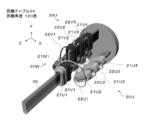
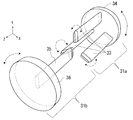
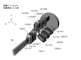
- FIG. 1 shows a block diagram, a perspective view, and a YZ plan view of the coil unit array device.
- the coil unit arrangement device 28 includes a control unit 29 and an arrangement unit 30.
- the array unit 30 is A holding portion 31a provided with a self-rotating coil unit support 33 for supporting the coil unit;
- a receiving portion 31b that includes an arrangement coil group support 35 that supports the arrangement coil group, and that rotates relative to the holding portion;
- a transport unit 31c for transporting the coils of the coil unit supported by the coil unit support 33 to the array coil group support 35; Is provided.
- the control unit 29 When forming an array coil group by taking out and arranging the coils from the coil unit based on the arrangement order, the connecting wire between the array coil group and the coil to be extracted is between the array coil group and another coil unit.
- the operations of the holding unit 31a, the receiving unit 31b, and the transport unit 31c are controlled so as to be arranged on the same side with respect to the crossover.
- the holding part 31a includes a coil unit support 33 having the required number of phases and a rotation table 34 to which the coil unit support 33 is connected. Each of the coil unit supports 33 can rotate.
- the receiving portion 31b is disposed to face the holding portion 31a, and includes an array coil group support 35 and a rotation table 36 to which the array coil group support 35 is connected. Similar to the holding part 31a, the array coil group support 35 can rotate. Further, the connection location between the array coil group support 35 and the rotary table 36 can be adjusted in the radial direction of the rotary table 36.
- the array coil group support body 35 and the coil unit support body 33 have a gap in the Z direction so that the crossover wires 22 can pass therethrough.
- the axial direction of rotation and rotation of the coil unit support 33, the array coil group support 35, and the rotation tables 34 and 36 is the Z direction. In the present embodiment, the Z direction substantially coincides with a center axis TT of a coil described later.
- the holding portion 31a and the receiving portion 31b are relatively rotated.
- the coil unit support 33 and the arrayed coil group support 35 of the holding portion 31a can rotate at an arbitrary rotation direction and rotation speed.
- the holding unit 31 a fixes the internal gear of the planetary gear, uses the rotation of the planetary gear carrier for rotation of the rotation table 34, and uses the rotation of the planetary gear for rotation of the coil unit support 33.
- 31a can be configured.
- the coil unit support 33 and the rotation table 34 may be driven by independent motors.
- the transport unit 31 c includes a plurality of claws 32 for gripping the coil, and at least one of the claws 32 can adjust a distance from the other claws 32.
- the transport unit 31c includes a mechanism that can move in two directions, the Y direction and the Z direction.
- the conveyance part 31c can hold
- sequence coil group support body 35 can be sent out to a Z direction as needed.
- the conveyance unit 31c may be configured by a multi-indirect robot.
- FIGS. 2 to 6 show a coil unit of an air-core coil and a molding process of the coil unit.
- the processing unit 10 includes a feeding unit 3 and a deforming unit 4.
- the feed unit 3 includes a drive roll 12a and a driven roll 12b disposed to face the drive roll 12a, and rotates the drive roll 12a while holding the coil wire 2 between the drive roll 12a and the drive roll 12b.
- the coil wire 2 is fed out from a supply unit (not shown) and conveyed to the deformation unit 4 while being shaped to be linear in the longitudinal direction.
- the deformation unit 4 includes a pressing roll 13, a support roll 14, and a pressing roll 15.
- the support roll 14 is arranged on one side of the conveyance path of the coil wire 2
- the push roll 15 is arranged on the other side of the conveyance path of the coil element 2 so as to move in a direction crossing the conveyance path. It has become.
- the coil wire 2 is deformed into a desired curvature by a pressing operation of pressing the coil wire 2 with the pressing roll 15.
- the coil wire 2 that has passed through the deformable portion 4 becomes a molded body 17.
- a guide 16 As shown in FIG. 3, the coil wire 2 that has passed through the deformable portion 4 becomes a molded body 17.
- the molded body 17 progresses spirally in the Z-axis direction while being guided by the guide 16 (in the perspective view of FIG. 2, the spiral shape is emphasized and drawn).
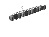
- processing is performed so that the molded body 17 forms a coil unit 20 in which a required number of coils 21 and crossover wires 22 are sequentially arranged.
- the coil unit 20 includes four concentrated winding coils 21 and five crossovers 22.
- the coil 21 is a multilayer ⁇ -winding coil in which straight portions and curved portions are alternately formed.
- the connecting wire 22 of the coil unit is formed so as to go around the central axis TT of the coil 21.
- the connecting wire 22 is designed to have a length necessary for connecting the coils 21 having the same phase when the coil 21 is disposed in the motor.
- Desirable circulation of the crossover wire 22 with respect to the central axis TT depends on the symmetry of the inner peripheral shape of the coil 21. Specifically, when the coil 21 is approximately rectangular, the coil 21 is approximately square. In this case, it is an integral multiple of 1 ⁇ 4 round. Not only this but the circumference with respect to the central axis TT of the crossover wire 22 may be set arbitrarily.
- the coil unit 20 may be formed by normal bobbin winding, not limited to the multilayer ⁇ winding.
- the description will be made in the case of the coil unit 20 in which the connecting wire 22 is rotated 360 degrees around the central axis TT.
- the U-phase coil unit is 20U
- the coils are 21U1, 21U2, 21U3, 21U4, and the transitions between the coils in order from the bottom of the page.
- the lines are described as 22U1, 22U2, 22U3. V phase and W phase are described similarly.
- the connecting wires 22 at both ends of the coil unit is a connecting line to the power source, and the other is a connecting line to the neutral point. However, in order to make it easier to see in the subsequent drawings, the drawing of the connecting wires 22 at both ends of the coil unit is omitted.
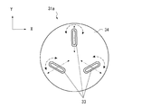
- FIG. 7 shows an XY plan view of the holding portion 31a in the initial state viewed from the receiving portion 31b.
- the central axis of the coil unit support 33 is located at 0 o'clock, 4 o'clock, and 8 o'clock when the rotary table 34 is regarded as a clock, and is approximately 120 degrees apart. If the angle of the coil unit support 33 at the 0 o'clock position is 90 degrees, the coil unit support 33 is connected to the rotary table 34 at a relationship of 30 degrees at 4 o'clock and 150 degrees at 8 o'clock. As shown by a two-dot chain line arrow in FIG. 7, the connection location between the coil unit support 33 and the rotary table 34 can be adjusted in the radial direction of the rotary table 34.
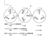
- FIG. 8 shows a change in the XY plan view when the holding portion 31a in operation from the receiving portion 31b is viewed in the Z direction.
- a ⁇ mark is written on the coil unit support 33.
- the coil unit support 33 rotates in the counterclockwise direction indicated by the alternate long and short dash line at the rotational speed ⁇ 2, and the rotation table 34 rotates at the rotational speed ⁇ 1 in the clockwise direction indicated by the broken line arrow.
- the rotary table 34 when the rotary table 34 is rotated 90 degrees, when attention is paid to the coil unit support 33 that was in the 0 o'clock position in the initial state, the coil unit support 33 moves to the 3 o'clock position. At this time, the ⁇ mark comes to the center side of the rotary table 34.
- the rotation table 34 is rotated 120 degrees, the coil unit support 33 that was at the 0 o'clock position in the initial state is at the 4 o'clock position. At this time, the angle coincides with the coil unit support 33 at the 4 o'clock position in the initial state.
- the rotating table 34 rotates once in the clockwise direction
- the coil unit support 33 rotates twice in the counterclockwise direction, but apparently the counterclockwise value obtained by subtracting one rotation of the revolution (the rotation of the rotating table 34). Rotate once around.
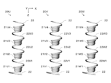
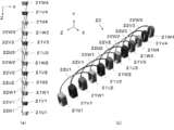
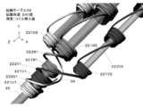
- FIG. 9 shows an initial state in which the coil units 20 for three phases are set on the coil unit support 33 of the holding portion 31a.
- the coil end on the Y axis + side in FIG. 5 is on the ⁇ mark side in FIG. 8, and the order of each phase is the position of 0:00 in the arrangement order when the rotary table 34 is rotated clockwise. It is installed so as to pass in the order of a certain U phase ⁇ V phase ⁇ W phase.
- the coil 21U1 of the coil unit 20U is gripped and transported by the transport unit 31c from the state of FIG.
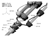
- the rotation table 34 is rotated 120 degrees clockwise to a position with a rotation angle of 120 degrees.
- the coil 21 ⁇ / b> V ⁇ b> 1 of the coil unit 20 ⁇ / b> V is fitted on the array coil group support 35 from the state of FIG. 11.
- the crossover 22U1 passes through the upper side of the coil 21V1 (the positive direction side of the Y axis) and connects the coil 21U1 and the coil 21U2.
- FIG. 13 from the state of FIG.
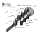
- the rotation table 34 is further rotated 120 degrees clockwise to a rotation angle of 240 degrees.
- the coil 21 ⁇ / b> W ⁇ b> 1 of the coil unit 20 ⁇ / b> W is fitted on the array coil group support 35 from the state of FIG. 13. From FIG. 12, even when the rotation table 34 rotates 120 degrees, the crossover wire 22 ⁇ / b> U ⁇ b> 1 is connected to the coil 21 ⁇ / b> U ⁇ b> 2 via the + X side when viewed from the array coil group support 35.
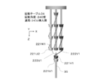
- the rotation table 34 is further rotated 120 degrees clockwise to a rotation angle of 360 degrees.
- the coil 21 ⁇ / b> U ⁇ b> 1 fitted on the array coil group support 35 is placed in the Z direction from the state of FIG. 15, and the coil 21 ⁇ / b> U ⁇ b> 2 of the coil unit 20 ⁇ / b> U is fitted on the array coil group support 35.
- the connecting wire 22U1 is rotated by the rotation of the rotation table 34 of the holding portion 31a and the rotation of the coil unit support 33, and the -Z of the coil 21W1.
- Crossover 22U (n) is between crossover 22W (n-1) and crossover 22V (n)
- the crossover line 22V (n) is between the crossover line 22U (n) and the crossover line 22W (n)
- the crossover line 22W (n) is between the crossover line 22V (n) and the crossover line 22V (n + 1).
- the relative positional relationship between the central axes of the coil unit support 33 is constant.
- the structure of the apparatus can be simplified, and the main motion is a rotational motion, so that there is an advantage that it is easy to speed up the operation.
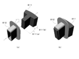
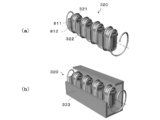
- FIG. 19 is a perspective view of a split stator core 811 that forms a stator of a motor having a rotor inside.
- the divided stator core 811 is formed by laminating electromagnetic steel plates formed by pressing or the like, and a part thereof is integrated by caulking or welding. Further, it is composed of a teeth portion 811 (a) and a yoke portion 811 (b) for arranging the coil 21, and as shown in FIG. 19 (b), before the coil 21 is arranged on the teeth portion 811 (a). Then, the insulating member 812 is fitted in advance.
- FIG. 20 shows a schematic diagram of the fitting process.
- the split stator core 811 fitted with the insulating member 812 is brought into contact with the end surface of the array coil group support 35 that penetrates the air core portion of the array coil group 23, and the coil 21 of the array coil group 23 is split into the split stator. Fit into the core 811.
- the split stator core fitted with the coil 21 can be continuously subjected to the fitting process by sliding in the direction intersecting the axial direction of the arrayed coil group support 35 that supports the arrayed coil group 23.
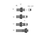
- a detailed process of fitting the coil 21 to the split stator core 811 while focusing on one coil 21 is shown in FIG. From the initial state of FIG. 21A, as shown in FIG.
- the divided stator core 811 fitted with the insulating member 812 and the arrayed coil group support 35 that supports the arrayed coil group 23 are brought into contact with each other. Monkey. Thereafter, as shown in FIG. 21 (c), the guide tape 71 is wound so that the arrayed coil group support 35 and the divided stator core 811 are integrated, and at least part of the insulating member 812 is included.
- the coil 21 is fitted to the split stator core 811 as shown in FIG.
- a linear stator 810 as shown in FIG. 22 is obtained.
- the linear stator 810 obtained in the fitting step is arranged in an annular shape and fixed by baking bamelling or the like, thereby obtaining a stator as shown in FIG.
- FIG. 25 (a) is a cross-sectional view of the stator of FIG. 23, but the space factor is increased by alternately changing the cross section of the adjacent coil shape from coil 24 to coil 25 as shown in FIG. 25 (b). be able to.
- the coil unit to be arranged in another arrangement step 1 by the coil unit arrangement apparatus of the first embodiment has the same configuration as that of the first embodiment except that the number of turns of the central axis TT of the crossover is 1/2. It has. This is effective when the length of the crossover is short and it is difficult to make one turn with respect to the central axis TT.
- the conveyance part 31c is the same as that of 1st embodiment, description is abbreviate
- FIG. 26 shows a coil unit 120 used in another arrangement step 1 by the coil unit arrangement apparatus of the first embodiment.
- the coil unit 120 includes four coils 121 and five connecting wires 122 that circulate around the central axis TT by a coil wire 2.
- the coil 121 prevents the coil 121 from spreading in the direction of the central axis TT and connects the coil portion 121 and the jumper wire 121 so that the coil wire 2 in the vicinity of the jumper wire 122 constituting the coil 121 is not deformed. Two places in the vicinity are restrained by the attachment tape P.
- the coils 121 before and after the crossover wire 122 are connected in a positional relationship that is rotated 180 degrees about the central axis TT. In this way, three coil units 120 are prepared. As shown in FIG.
- the three phases are the U phase, the V phase, and the W phase.
- the U-phase coil unit is 120U
- the coils are 121U1, 121U2, 121U3, 121U4,
- the lines are described as 122U1, 122U2, 122U3.
- V phase and W phase are described similarly.
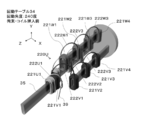
- FIG. 28 is a perspective view of the arrangement unit of the coil unit arrangement apparatus of the first embodiment.
- FIG. 29 shows a change in the XY plan view of the holding portion 31a in operation from the receiving portion 31b in the Z direction.
- the central axis of the coil unit support 33 is located at 0 o'clock, 4 o'clock, and 8 o'clock when the rotary table 34 is regarded as a clock, and is approximately 120 degrees apart. ing.
- the rotation angle of the rotation table 34 is 0 degree, if the angle of the coil unit support 33 at the 0 o'clock position is 90 degrees, the rotation angle is 150 degrees at 4 o'clock and 30 degrees at 8 o'clock.
- the moving table 34 is connected.
- the coil unit support 33 rotates in the counterclockwise direction indicated by the alternate long and short dash line at the rotational speed ⁇ 2, and the rotation table 34 rotates at the rotational speed ⁇ 1 in the clockwise direction indicated by the broken line arrow.
- the rotary table 34 when the rotary table 34 is rotated 90 degrees, when attention is paid to the coil unit support 33 that was in the 0 o'clock position in the initial state, the coil unit support 33 moves to the 3 o'clock position. At this time, since the coil unit support 33 rotates -135 degrees, it apparently rotates -45 degrees counterclockwise.
- the rotation table 34 is rotated 120 degrees, the coil unit support 33 that was at the 0 o'clock position in the initial state is at the 4 o'clock position. At this time, the angle coincides with the coil unit support 33 at the 4 o'clock position in the initial state.
- the rotary table 34 makes one clockwise rotation, the coil unit support 33 rotates 3/2 counterclockwise. At this time, apparently, one rotation of revolution (rotation of the rotation table 34) is subtracted and the rotation is halved counterclockwise.
- FIG. 30 shows an initial state in which the three-phase coil units 120 are set on the coil unit support 33 of the holding portion 31a.
- the initial state of each coil unit 120 is as follows.
- the coil unit 120U is installed on the coil unit support 33 at the 0 o'clock position so that the coil end to which the connecting wire 122 of the coil 121U1 is connected is on the outer diameter side of the turntable 34.
- the coil unit 120V is installed on the coil unit support 33 at the 8 o'clock position so that the coil end to which the connecting wire 122 of the coil 121V1 is connected is on the center side of the rotary table 34.
- the coil unit 120W is installed on the coil unit support 33 at the 4 o'clock position so that the coil end to which the connecting wire 122 of the coil 121W1 is connected is on the outer diameter side of the rotary table 34.
- the coil 121U1 of the coil unit 120U is gripped and transported by the transport unit 31c from the initial state of FIG.
- the rotation table 34 is rotated 120 degrees clockwise to a position where the rotation angle is 120 degrees, and the coil 121V1 of the coil unit 120V is arranged as an array coil group support. 35.
- the connecting wire 122 is connected to the coil 121V1 of the coil unit 120V to be fitted to the array coil group support 35 and the coil 121U2 located at the tip of the coil unit support 33 at the 4 o'clock position.
- the coil end on the other side becomes the outer diameter side of the rotary table 34.
- the coil end on the side to which the connecting wire 122 is connected is the center side of the rotary table 34.
- the crossover wire 122U1 passes through the upper side of the coil 121V1 (the positive direction side of the Y axis) and connects the coil 121U1 and the coil 121U2.
- the rotation table 34 is further rotated 120 degrees clockwise to a position where the rotation angle is 240 degrees, and the coil 121W1 of the coil unit 120W is arranged in the array coil group. Fit onto the support 35.
- the connecting wire 122U1 is connected to the coil 121U2 via the back side (minus side in the Z direction) of the coil 121W1.
- the rotation table 34 is further rotated 120 degrees clockwise to a rotation angle of 360 degrees, and is fitted on the array coil group support 35.
- the coil 121U1 is fed in the Z direction, and the coil 121U2 of the coil unit 120U is fitted on the array coil group support 35.
- the connecting wire 122U1 is moved to the rear side of the coil 121W1 by the rotation of the rotation table 34 of the holding portion 31a and the rotation of the coil unit support 33 ( Passes through the gap between the coil unit support 33 and the arrayed coil group support 35 in the Z direction.
- the coil unit 120 Each time the rotation table 34 makes one rotation, the coil unit 120 apparently makes a half turn counterclockwise, so all the coils 121 fitted to the array coil group support 35 are in the same direction. Therefore, all the coils 121 are repeatedly fitted to the array coil group support 35 by repeating the above-described operation, so that the crossover wires 122 are not crossed and arranged in a line in the order in which they are arranged on the stator.
- the arranged array coil group 23 can be obtained.
- FIG. 35 shows a coil unit 220 used in another arranging step 2 by the coil unit arranging apparatus of the first embodiment.
- the coil unit 220 In the coil unit 220, four coils 221 and five crossover wires 222 that make a half turn around the central axis TT are constituted by the coil wire 2.
- the coil 221 prevents the coil 221 from spreading in the direction of the central axis TT and connects the coil portion 221 and the jumper wire 221 so that the coil wire 2 in the vicinity of the jumper wire 222 constituting the coil 221 is not deformed. 3 places including 2 places in the vicinity are restrained by the attachment tape P.
- the coils 221 before and after the crossover 222 are connected in the same positional relationship with the central axis TT as an axis.
- the drawing of the attachment tape P is omitted for easy understanding.
- three coil units 220 are prepared.
- the three phases are the U phase, the V phase, and the W phase.
- the U phase coil unit is 220U, and the coils are 221U1, 221U2, 221U3, 221U4
- the lines are described as 222U1, 222U2, 222U3.
- V phase and W phase are described similarly.
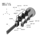
- FIG. 37 is a perspective view of the arrangement unit of the coil unit arrangement device of the first embodiment.
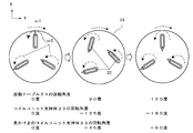
- FIG. 38 shows a change in the XY plan view of the holding unit 31a in another arrangement step 2 performed by the coil unit arrangement apparatus of the first embodiment during operation from the receiving unit 31b when viewed in the Z direction.
- the central axis of the coil unit support 33 is located at 0 o'clock, 4 o'clock, and 8 o'clock when the rotary table 34 is regarded as a clock, and is approximately 120 degrees apart. ing. Further, all the coil unit supports 33 are connected to the rotating table 34 at the same angle.
- the coil unit support 33 rotates in the counterclockwise direction indicated by the alternate long and short dash line at the rotational speed ⁇ 2, and the rotation table 34 rotates at the rotational speed ⁇ 1 in the clockwise direction indicated by the broken line arrow.
- the rotation table 34 When the rotation table 34 is rotated 120 degrees, the position of the coil unit support 33 at the 0 o'clock position in the initial state coincides with the position of the coil unit support 33 at the 4 o'clock position in the initial state. Become. When the rotating table 34 makes one clockwise rotation, the coil unit support 33 makes one counterclockwise rotation, so that the same orientation is maintained in appearance.
- FIG. 39 shows an initial state in which the coil units 220 for three phases are set on the coil unit support 33 of the holding portion 31a that moves in this manner.
- the initial state of each coil unit 220 is as follows.
- the coil unit 220U is installed on the coil unit support 33 at the 0 o'clock position so that the coil end to which the connecting wire 222 of the coil 221U1 is connected is on the outer diameter side of the rotary table 34.
- the coil unit 220V is installed on the coil unit support 33 at 8 o'clock and the coil unit 220W is installed at 4 o'clock so as to be in the same direction as the coil unit 220U.
- the coil 221U1 of the coil unit 220U is gripped and transported by the transport unit 31c and fitted onto the arrayed coil group support 35.
- the rotation table 34 is rotated 120 degrees clockwise to a position where the rotation angle is 120 degrees, and the coil 221V1 of the coil unit 220V is arranged as an array coil group support. 35.
- the crossover wire 222U1 passes through the upper side of the coil 221V1 (the positive direction side of the Y axis) and connects the coil 221U1 and the coil 221U2.
- the rotation table 34 is further rotated 120 degrees clockwise to a position where the rotation angle is 240 degrees, and the coil 221U1 and the coil are rotated using the restraining tool 39.
- the connecting wire 222U1 connecting 221U2 is restrained.
- the crossover wire 222U1 restrained by the restraining tool 39 goes around the plus side in the X direction with respect to the coil 221W1.
- FIG. 44 when the coil 221W1 is fitted to the array coil group support 35, the crossover wire 222U1 is connected to the coil 221U2 via the back side (minus side in the Z direction) of the coil 221W1.
- the crossover wire 222U1 is connected to the rotation table 34 of the holding portion 31a.
- the coil 221W1 passes through the back side (minus side in the Z direction), and further passes through the gap in the Z direction between the coil unit support 33 and the arrayed coil group support 35. .
- the arrangement similar to FIG. 18 is arranged in a line in the arrangement order on the stator without crossing the connecting wires 222.
- the coil group 23 can be obtained.
- FIG. 45 is a perspective view of the rotation table 34 before the rotation angle is 240 degrees and the coil 221W1 is inserted into the array coil group support 35.
- the coil unit arrangement device By using the coil unit arrangement device according to the present invention, handling is possible in a state where the connecting wire of the coil unit circulates around the central axis TT. Since it is not linear, the length in the Z-axis direction necessary for the holding portion 31a when obtaining the array coil group can be reduced. Even if the number of coils in the coil unit is increased, the rotation of the rotation table 34 of the holding unit 31a, the rotation of the coil unit support 33, and the coil at a specific position are gripped and transferred by the transfer unit 31c to arrange the coils. It can be a repetitive operation to fit the group support 35. Furthermore, the first embodiment can be implemented by a simple mechanism because of the rotational movement in which the central axes of the coil units do not move relative to each other. In the prior art, a gripping mechanism corresponding to the number of coils of the coil unit is necessary, and the number of coils to be gripped needs to be reduced as the process proceeds. Further, the central axis of the coil unit has to be moved relatively.
- the rotation rate of the coil unit support 33 is maintained with respect to one rotation of the rotation table 34 and the rotation table 36 relative to each other, even if the rotational speed ⁇ 1 of the coil unit support 33 varies. Good.
- the amount of winding of the coil unit with respect to the central axis of the connecting wire can be arbitrarily set in the molding process, but there may be a connecting wire with a different number of turns in the coil unit. This case can be dealt with by appropriately adjusting the amount of rotation of the carp unit support 33 that supports the coil unit in the arranging step.
- FIG. 48 shows a divided support used in the second embodiment.
- the divided support body 37 has a structure that can be continuously engaged with the other divided support bodies 37 and has at least one or more through holes.
- the coil unit support 33 and the array coil group support 35 are configured by combining the split support 37 as shown in FIG.
- the turntable 36 to which the array coil group support 35 is connected also has a through hole.
- the array coil group support 35 is set to face the coil unit support 33 at the 0 o'clock position when the holding portion 31a rotates.
- the transport unit 31 c includes a guide bar 38 that penetrates the divided support 37 and the through hole of the rotary table 36.
- the retracted guide bar 38 moves in the direction of the solid line arrow, and the leading end of the coil unit support 33 is obtained.
- the split support 37 at the tip is moved in the direction of the white arrow while being guided by the guide bar 38 and connected to the array coil group support 35.
- the guide bar 38 is retracted in the direction of the solid line arrow so as not to hinder the rotation of the holding portion 31a.
- the rotation table 36 moves in the direction of the black arrow in FIG. 50C according to the interval between the arrayed coil group support 35 and the coil unit support 33 that faces next.
- the holding unit 31a may be moved in the ⁇ Z direction.
- the coil unit support body 33 and the arrangement
- FIG. 51 shows a coil unit 320 used in the third embodiment.
- the coil unit 320 four coils 321 and five connecting wires 322 that make one round of the central axis are constituted by the coil wire 2.
- the coil 321 is fitted to the split stator core 811 fitted with the insulating member 812 by applying a method similar to the fitting step of the first embodiment shown in FIG. 20 to the coil unit.
- the coil unit 320 having the split stator core can be rotated while being rotated, as in the first embodiment.
- the coil can be implemented so that the central axis of the coil intersects the longitudinal direction of the coil unit support 333.
- the cylindrical coil unit support 333 has an opening through which the claw 32 of the transport unit 31c passes so that the cross section of the coil unit support 333 can be used to send out or fix a predetermined coil 321. Is desirable.
- the coil unit 320 may be supported and rotated by a rod-shaped magnetic body by utilizing the fact that the material of the divided stator core is a ferromagnetic body. Thereby, even if it is the concentrated winding made by the normal bobbin winding, the same operation as the coil having the air core portion can be performed.
- a coil unit array device according to a fourth embodiment of the present invention will be described with reference to FIGS. 53 to 55.
- the fourth embodiment is different from the first embodiment in that the coil unit support is moved one by one. Differences from the first embodiment will be described.
- the three coil units 20 in FIG. 5 are used as the coil units.
- the tip end in the Z-axis direction supported by the coil unit support 33 is used.
- the case where the array coil group in which the coils 21 are arrayed in a predetermined array order is obtained by fitting the coil 21 on the side to the array coil group support 35 will be described.
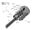
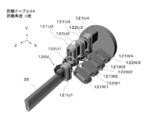
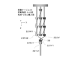
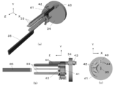
- FIG. 53 shows a perspective view, a YZ plan view, and an XY plan view of an arrangement portion used in the fourth embodiment.
- the holding body 41 is fixed to a base (not shown) and holds the coupling 42 to which the coil unit support 33 is connected.
- the holding body 41 matches the trajectory that passes through the holding body 41 of the coupling 42 and the trajectory that the rotating body 43 rotates as the rotating table 34 rotates. It is desirable to install so as to.
- the holding body 41 includes a retrograde prevention tool 411 in order to prevent the coupling 42 put in the holding body 41 from going backward.
- the retrograde prevention tool 411 rotates around a rotation shaft 414 that is supported by a bearing 413 fixed to the holder 41.
- the stopper 412 restricts the rotation of the retrograde prevention tool 411.
- the anti-reverse tool 411 does not prevent the coupling 42 from entering the holding body 41, but prevents it from going backward.
- the coupling 42 and the rotating body 43 are provided with two or more through-holes through which the connection bar 44 passes.
- the through bar 44 can reciprocate in the Z direction, and the through bar 44 passes through the coupling 42 and the rotating body 43 to rotate and rotate the coil unit support 33 connected to the coupling 42.
- the coupling 42 is desirably provided with a slit so as to be stably held by the holding body 41. In the subsequent drawings, drawing related to the retrograde preventer 411 is omitted.
- the coil unit support 33 In the initial state, as shown in FIG. 55 (a), the coil unit support 33 is held by the holding body 41 in a state of being adjacent to each other around the 9 o'clock position. As shown in FIG. 56 (a), the rotating table 34 is rotated and the rotating body 43 is rotated from the state shown in FIG. 55 (a), so that the coupling 42 and the rotating body 43 closer to the 0 o'clock position.
- the connection bar 44 is penetrated by matching the through holes.
- the coil unit support 33 rotates in the counterclockwise direction indicated by the alternate long and short dash line at the rotational speed ⁇ 2, and the rotation table 34 rotates at the rotational speed ⁇ 1 in the clockwise direction indicated by the broken line arrow.
- the coil is rotated by the rotation of the rotation table 34 and the rotation of the coil unit support 33 which are rotated through the through bar 44 from the state of FIG. 56 (a).
- the unit 20 rotates while rotating from 0 o'clock to 4 o'clock. Thereafter, the other coil unit 20 held by the holding body 41 is pushed up and rotated to the 8 o'clock position.
- 56 (b) is a YZ plan view of FIG. 55 (b)
- FIG. 56 (c) is a YZ plan view of FIG. 55 (c).
- 56D is an XY plan view of the rotating coil unit 20 when the other coil unit 20 is pushed up and rotated to the 8 o'clock position.
- the through bar 44 is moved in the -Z direction at the 8 o'clock position to release the connection with the rotary table 34.
- the turning table 34 is turned and the rotating body 43 is rotated so that the through hole of the rotating body 43 is aligned with the coupling 42 closer to 0:00.
- the coil units 20 are installed in the order of the U phase, the V phase, and the W phase from the coil unit support 33 closer to 0 o'clock.
- the coil unit support 33 is rotated one by one through the through bar 44. And rotate.
- the coil 21 on the tip side in the Z-axis direction supported by the coil unit support 33 is used as the array coil group support 35. An array coil group in which the coils 21 are arranged in a predetermined arrangement order is obtained.
- the coil unit support 33 to be rotated is one, handling of the crossover wire is facilitated. Therefore, even when the number of phases of the motor is large, the array coil group can be obtained with certainty.
Abstract
A coil unit arrangement device that forms an arranged coil group by arranging in a prescribed arrangement order each of the coils of coil units in which multiple coils corresponding to multiple phases are connected with a crossover wire for each phase, said coil unit arrangement device configured so as to be equipped with: a retaining part equipped with rotatable coil unit support bodies that support the coil units; and a receiving part, which is equipped with an arranged coil group support body that supports the arranged coil group, and rotates relative to the retaining part.
Description
本発明は、複数のコイル及び渡り線が構成されたコイルユニットを、必要相数用いて回転機器を製造する工程のうち、コイルユニットを所要配列状態に配列する工程に用いるコイルユニット配列装置に関するものである。
The present invention relates to a coil unit arranging device used in a step of arranging a coil unit in a required arrangement state among steps of manufacturing a rotating device by using a necessary number of phases for a coil unit having a plurality of coils and connecting wires. It is.
電気自動車やハイブリッド自動車用モータは、小型化、高出力化が求められている。コイル間の結線処理にともなう電気抵抗の上昇を抑えるため、1相分の複数コイルを1本のコイル素線により成形した多連巻きコイルを利用することで、性能向上が見込まれる。多連巻きの製造方法および製造装置に関する従来技術として、特許文献1、特許文献2および特許文献3がある。
¡Motors for electric vehicles and hybrid vehicles are required to be smaller and have higher output. In order to suppress an increase in electrical resistance due to the connection processing between the coils, performance improvement is expected by using a multiple winding coil in which a plurality of coils for one phase are formed by one coil wire. There are Patent Document 1, Patent Document 2, and Patent Document 3 as conventional techniques related to a method for manufacturing multiple windings and a manufacturing apparatus.
特許文献1には、コイル、スロットレスモータ及びコイルの製造方法についての技術が開示されている。
具体的には、導線を固定する固定具と、導線を直角方向に押圧する押圧具とを備えた折り曲げ装置を用い、素材である導線を所定長さ突出させて根元を前記固定具で固定した状態で、前記押圧具で導線の突出部を平面上で直角方向に押圧して当該導線を直角に折り曲げた後、さらに、固定具から導線を所定長さ突出させて直角に折り曲げる操作を順次繰り返すことにより、角形渦巻状の渦巻体を形成することを特徴とするコイルの製造方法が開示されている。Patent Document 1 discloses a technique regarding a coil, a slotless motor, and a method for manufacturing the coil.
Specifically, using a bending device provided with a fixing tool for fixing the conducting wire and a pressing tool for pressing the conducting wire in a perpendicular direction, the conducting wire as a material protrudes a predetermined length and the root is fixed with the fixing tool. In this state, after pressing the protruding portion of the conducting wire with the pressing tool in a right angle direction on the plane to bend the conducting wire at a right angle, the operation of projecting the conducting wire by a predetermined length from the fixture and bending it at a right angle is sequentially repeated. Thus, a method for manufacturing a coil is disclosed, in which a rectangular spiral body is formed.
具体的には、導線を固定する固定具と、導線を直角方向に押圧する押圧具とを備えた折り曲げ装置を用い、素材である導線を所定長さ突出させて根元を前記固定具で固定した状態で、前記押圧具で導線の突出部を平面上で直角方向に押圧して当該導線を直角に折り曲げた後、さらに、固定具から導線を所定長さ突出させて直角に折り曲げる操作を順次繰り返すことにより、角形渦巻状の渦巻体を形成することを特徴とするコイルの製造方法が開示されている。
Specifically, using a bending device provided with a fixing tool for fixing the conducting wire and a pressing tool for pressing the conducting wire in a perpendicular direction, the conducting wire as a material protrudes a predetermined length and the root is fixed with the fixing tool. In this state, after pressing the protruding portion of the conducting wire with the pressing tool in a right angle direction on the plane to bend the conducting wire at a right angle, the operation of projecting the conducting wire by a predetermined length from the fixture and bending it at a right angle is sequentially repeated. Thus, a method for manufacturing a coil is disclosed, in which a rectangular spiral body is formed.
特許文献2には、電動機の突極集中巻ステータの製造方法についての技術が開示されている。
具体的には、渡り部14Tを介して同一の巻線14によって巻回され、1階層L1からn階層Lnまで、高さ位置が次第に低くなるように階段状に配列された複数のコイル13からなる3相分のコイル群18を、各階層において3相の並び順が一致するように配置する。いずれかを基準階層として、基準階層に近いコイル13から順に、基準階層の高さと同じ高さとなるように、他相の渡り部14Tを迂回して移動する作業を、すべてのコイル13が同一の高さになるまで続けて1列に整列させ、ステータコア11のティース11bに挿入するステータの製造方法が開示されている。Patent Document 2 discloses a technique regarding a method for manufacturing a salient pole concentrated winding stator of an electric motor.
Specifically, from the plurality ofcoils 13 wound by the same winding 14 via the crossover portion 14T and arranged in a stepped manner so that the height position gradually decreases from the first layer L1 to the nth layer Ln. The three-phase coil group 18 is arranged so that the arrangement order of the three phases is the same in each layer. With any one of the coils 13 being the same as the reference layer, the work of moving around the crossing portion 14T of the other phase so as to be the same height as the reference layer in order from the coil 13 close to the reference layer is the same. A method of manufacturing a stator that is continuously aligned in a row until reaching a height and inserted into the teeth 11b of the stator core 11 is disclosed.
具体的には、渡り部14Tを介して同一の巻線14によって巻回され、1階層L1からn階層Lnまで、高さ位置が次第に低くなるように階段状に配列された複数のコイル13からなる3相分のコイル群18を、各階層において3相の並び順が一致するように配置する。いずれかを基準階層として、基準階層に近いコイル13から順に、基準階層の高さと同じ高さとなるように、他相の渡り部14Tを迂回して移動する作業を、すべてのコイル13が同一の高さになるまで続けて1列に整列させ、ステータコア11のティース11bに挿入するステータの製造方法が開示されている。
Specifically, from the plurality of
特許文献3には、集中巻線式ステータの製造方法及びその製造方法についての技術が開示されている。
具体的には、複数の集中巻線部を同一の導線にて連続成形することでコイルユニットを形成し、所定相とする前記コイルユニットを、他相とする前記コイルユニットが有する前記集中巻線部毎に一回転させて、前記他相のコイルユニットの前記集中巻線部間に、前記所定相のコイルユニットの前記集中巻線部を配置する動作を繰り返すことで、各相の前記コイルユニットの前記集中巻線部を、ステータへの配置順序にしたがって整列配置させ、各相全ての前記コイルユニットを整列配置させることで形成されたコイルユニット群が有する前記集中巻線部に、前記ステータが備えるティース部を嵌装するコイルの製造方法が開示されている。Patent Document 3 discloses a manufacturing method of a concentrated winding stator and a technique related to the manufacturing method.
Specifically, a coil unit is formed by continuously forming a plurality of concentrated winding portions with the same conducting wire, and the concentrated winding of the coil unit having a predetermined phase as the coil unit. The coil unit of each phase is rotated by repeating the operation of rotating the concentrated winding part of the coil unit of the predetermined phase between the concentrated winding parts of the coil unit of the other phase by rotating once for each part. The concentrated winding portions of the coil units are arranged in accordance with the arrangement order on the stator, and the coil units of all the phases are aligned and arranged. The manufacturing method of the coil which inserts the teeth part with which it is provided is disclosed.
具体的には、複数の集中巻線部を同一の導線にて連続成形することでコイルユニットを形成し、所定相とする前記コイルユニットを、他相とする前記コイルユニットが有する前記集中巻線部毎に一回転させて、前記他相のコイルユニットの前記集中巻線部間に、前記所定相のコイルユニットの前記集中巻線部を配置する動作を繰り返すことで、各相の前記コイルユニットの前記集中巻線部を、ステータへの配置順序にしたがって整列配置させ、各相全ての前記コイルユニットを整列配置させることで形成されたコイルユニット群が有する前記集中巻線部に、前記ステータが備えるティース部を嵌装するコイルの製造方法が開示されている。
Specifically, a coil unit is formed by continuously forming a plurality of concentrated winding portions with the same conducting wire, and the concentrated winding of the coil unit having a predetermined phase as the coil unit. The coil unit of each phase is rotated by repeating the operation of rotating the concentrated winding part of the coil unit of the predetermined phase between the concentrated winding parts of the coil unit of the other phase by rotating once for each part. The concentrated winding portions of the coil units are arranged in accordance with the arrangement order on the stator, and the coil units of all the phases are aligned and arranged. The manufacturing method of the coil which inserts the teeth part with which it is provided is disclosed.
しかし、特許文献1から特許文献3には以下に説明する課題がある。
特許文献1は、線材(導線)を所定長さ突出させ、固定具で線材を固定した状態で押圧具を押圧し、線材を外周面が丸いガイド22に沿うように曲げる。
加工が進むに連れ、既に加工が完了し、コイルを構成する加工済み線材が多くなる。そのため、線材を所定長さ送り出す工程や曲げる工程において、加工済み素線を保持しながら各工程に応じて平行移動あるいは回転運動させる必要がある。これにより、同相のコイル数が多くなるほど加工済み素線が装置等と干渉しないように十分なスペースを確保する必要がある。 However,Patent Documents 1 to 3 have the problems described below.
InPatent Document 1, a wire (conductive wire) is projected for a predetermined length, the pressing tool is pressed in a state where the wire is fixed by a fixing tool, and the wire is bent along a guide 22 having a round outer peripheral surface.
As the processing proceeds, the processing is already completed and the processed wire constituting the coil increases. For this reason, in the process of feeding the wire to a predetermined length or the process of bending, it is necessary to translate or rotate according to each process while holding the processed strand. Accordingly, it is necessary to secure a sufficient space so that the processed wire does not interfere with the apparatus or the like as the number of coils in the same phase increases.
特許文献1は、線材(導線)を所定長さ突出させ、固定具で線材を固定した状態で押圧具を押圧し、線材を外周面が丸いガイド22に沿うように曲げる。
加工が進むに連れ、既に加工が完了し、コイルを構成する加工済み線材が多くなる。そのため、線材を所定長さ送り出す工程や曲げる工程において、加工済み素線を保持しながら各工程に応じて平行移動あるいは回転運動させる必要がある。これにより、同相のコイル数が多くなるほど加工済み素線が装置等と干渉しないように十分なスペースを確保する必要がある。 However,
In
As the processing proceeds, the processing is already completed and the processed wire constituting the coil increases. For this reason, in the process of feeding the wire to a predetermined length or the process of bending, it is necessary to translate or rotate according to each process while holding the processed strand. Accordingly, it is necessary to secure a sufficient space so that the processed wire does not interfere with the apparatus or the like as the number of coils in the same phase increases.
特許文献2は、所定相の未配列コイルの位置関係を固定した状態で、他相の渡り線を迂回して移動する作業が必要である。つまり、所定相のコイルユニットの未配列のコイルの位置関係を固定した状態で、他相のコイルユニットの未配列コイルを乗り越える、「各相のコイルユニットの中心軸の相対的移動」が必要となる。
この配列作業は、コイルユニット内のコイル数が増えるほど移動作業が複雑で困難になる。 InPatent Document 2, it is necessary to move around a crossover line of another phase while fixing a positional relationship of unarranged coils of a predetermined phase. In other words, “relative movement of the central axis of the coil unit of each phase” is necessary to overcome the unarranged coil of the coil unit of the other phase while fixing the positional relationship of the unarranged coil of the coil unit of the predetermined phase. Become.
This arrangement work becomes more complicated and difficult as the number of coils in the coil unit increases.
この配列作業は、コイルユニット内のコイル数が増えるほど移動作業が複雑で困難になる。 In
This arrangement work becomes more complicated and difficult as the number of coils in the coil unit increases.
特許文献3は、コイルユニットを複数相分形成し、所定相とするコイルユニットが他相とするコイルユニットの集中巻線部毎に一回転させられることにより、他相のコイルユニットの集中巻部間に所定相のコイルユニットの集中巻部が配置される。
この方法は、所定相の集中巻線部の動作を統一しなければ、渡り線にネジレが発生する。また、前進動作中において所定相とするコイルユニットの渡り線と他相のコイルユニットの渡り線との干渉が発生する。そのためコイルユニット内のコイル数が多くなるほど、特許文献2以上に作業が複雑で困難となる。 InPatent Document 3, a coil unit is formed in a plurality of phases, and a coil unit having a predetermined phase is rotated once for each concentrated winding part of the coil unit having the other phase, so that the concentrated winding part of the coil unit of the other phase is obtained. A concentrated winding portion of a coil unit of a predetermined phase is disposed between them.
In this method, if the operation of the concentrated winding portion of a predetermined phase is not unified, twisting occurs in the crossover. Further, during the forward movement, interference occurs between the connecting wire of the coil unit that is a predetermined phase and the connecting wire of the coil unit of the other phase. Therefore, as the number of coils in the coil unit increases, the work becomes more complicated and difficult than inPatent Document 2.
この方法は、所定相の集中巻線部の動作を統一しなければ、渡り線にネジレが発生する。また、前進動作中において所定相とするコイルユニットの渡り線と他相のコイルユニットの渡り線との干渉が発生する。そのためコイルユニット内のコイル数が多くなるほど、特許文献2以上に作業が複雑で困難となる。 In
In this method, if the operation of the concentrated winding portion of a predetermined phase is not unified, twisting occurs in the crossover. Further, during the forward movement, interference occurs between the connecting wire of the coil unit that is a predetermined phase and the connecting wire of the coil unit of the other phase. Therefore, as the number of coils in the coil unit increases, the work becomes more complicated and difficult than in
そこで本発明は、このような課題を解決するために、複数のコイルを同一導線により成形する際の加工スペースをコンパクトにするとともに、その後の所用相数のコイルユニットのコイルを渡り線の交差が生じないようにモータ配設順に配列する配列作業が容易で、効率的なコイルユニット配列装置を提供することを目的とする。
Therefore, in order to solve such a problem, the present invention reduces the processing space when forming a plurality of coils with the same conducting wire, and crosses over the coils of the coil unit having the required number of phases thereafter. It is an object of the present invention to provide an efficient coil unit arraying device that is easy to arrange in order of motor arrangement so that it does not occur.
(1)複数相に対応する複数のコイルが相毎に渡り線で接続されたコイルユニットの当該各コイルを所定の配列順序で配列して配列コイル群を形成するコイルユニット配列装置であって、
前記コイルユニットを支持する自転可能なコイルユニット支持体を備えた保持部と、
前記配列コイル群を支持する配列コイル群支持体を備え、前記保持部に対し相対的に回動する受け部と、
を備えているコイルユニット配列装置。 (1) A coil unit arraying device that forms an array coil group by arraying the coils of a coil unit in which a plurality of coils corresponding to a plurality of phases are connected by crossovers for each phase in a predetermined array order,
A holding portion including a self-rotating coil unit support that supports the coil unit;
A receiving section that includes an array coil group support that supports the array coil group, and that rotates relative to the holding section;
A coil unit array device comprising:
(2)前記コイルユニット支持体に支持されたコイルユニットのコイルを、前記配列コイル群支持体へ搬送する搬送部を備えている(1)に記載のコイルユニット配列装置。
(2) The coil unit arraying device according to (1), further including a transport unit that transports the coils of the coil unit supported by the coil unit support to the array coil group support.
(3)前記コイルユニットから前記配列順序に基づいて前記コイルを取り出して配列することで前記配列コイル群を形成する際に、前記配列コイル群と取り出すコイルとの間の前記渡り線が前記配列コイル群と他の前記コイルユニットとの間の前記渡り線に対して同じ側に配置されるように前記保持部、前記受け部および前記搬送部を制御する制御部を備えている(2)に記載のコイルユニット配列装置。
(3) When forming the array coil group by extracting and arranging the coils from the coil unit based on the array order, the connecting wire between the array coil group and the coil to be extracted is the array coil. (2) The control unit that controls the holding unit, the receiving unit, and the transport unit so as to be disposed on the same side with respect to the crossover between the group and the other coil unit. Coil unit array device.
(4)前記コイルユニット支持体が、分割支持体を組み合せて構成されている(1)から(3)のいずれかに記載のコイルユニット配列装置。
(4) The coil unit arraying device according to any one of (1) to (3), wherein the coil unit support is configured by combining divided supports.
(5)前記配列コイル群支持体が、分割支持体を組み合せて構成されている(1)から(4)のいずれかに記載のコイルユニット配列装置。
(5) The coil unit arraying device according to any one of (1) to (4), wherein the array coil group support body is configured by combining divided support bodies.
(6)前記コイルユニット支持体、配列コイル群支持体が、貫通口を備えるとともに、前記搬送部は、前記貫通口を貫通する抜き差し可能なガイドバーを備え、
前記コイルユニット支持体と配列コイル群支持体とを前記ガイドバーにより連接して前記コイルを搬送する(2)から(5)のいずれかに記載のコイルユニット配列装置。 (6) The coil unit support body and the array coil group support body include a through-hole, and the transport unit includes a guide bar that can be inserted and removed through the through-hole,
The coil unit array device according to any one of (2) to (5), wherein the coil unit support and the array coil group support are connected by the guide bar to convey the coil.
このような特徴を有する本発明のコイルユニット配列装置は以下のような作用、効果が得られる。複数のコイル及び渡り線を順次配列した相毎のコイルユニットから固定子の配列順序に基づいてコイルを取り出して配列するようにしているので、様々な配列順序の固定子に対応することができる。
The coil unit arraying device of the present invention having such characteristics can provide the following operations and effects. Since the coils are taken out and arranged based on the arrangement order of the stators from the coil units for each phase in which a plurality of coils and crossovers are sequentially arranged, it is possible to deal with the stators in various arrangement orders.
また、コイルユニットからコイルを一旦取り出して配列しているので、コイルの数が増加しても同じ配列処理を繰り返して行うことで確実に固定子の配列順序で配列することができる。
In addition, since the coils are once taken out from the coil unit and arranged, even if the number of coils increases, the same arrangement process can be repeated to ensure the arrangement in the stator arrangement order.
コイルを取り出して配列する際に、配列コイル群と取り出すコイルとの間の渡り線が配列コイル群と他のコイルユニットとの間の渡り線に対して同じ側に配置されるようにコイルを取り出すコイルユニットを他のコイルユニットに対して配置するようにしているので、渡り線を交差させることなく配列コイル群にコイルを追加して配列することができる。
When the coils are taken out and arranged, the coils are taken out so that the connecting wire between the arranged coil group and the extracted coil is arranged on the same side with respect to the connecting wire between the arranged coil group and another coil unit. Since the coil unit is arranged with respect to the other coil units, it is possible to add and arrange the coils to the array coil group without crossing the crossover wires.
また、コイルユニット同士を配置しなおすことで渡り線を交差しないようにしているので、取り出すコイルを配列コイル群に追加する処理が単純化でき、作業効率の向上を図ることが可能となる。
In addition, since the crossover lines are not crossed by re-arranging the coil units, the process of adding the coil to be taken out to the array coil group can be simplified, and the work efficiency can be improved.
従来は、1本の導体で複数のコイルおよび渡り線からなるコイルユニットを成形する際に、成形済みコイルユニットを成形加工に応じて回転する必要がある。成形済みコイルユニットが回転する回転軸から最大コイルユニット長さだけ作業スペースを確保する必要があった。本発明によれば、回転軸方向に成形済みコイルが進展するため作業スペースをコンパクトにできる。
Conventionally, when forming a coil unit composed of a plurality of coils and crossovers with a single conductor, it is necessary to rotate the formed coil unit in accordance with the forming process. It was necessary to secure a working space by the maximum coil unit length from the rotating shaft on which the formed coil unit rotates. According to the present invention, since the formed coil advances in the direction of the rotation axis, the work space can be made compact.
また、必要相数のコイルユニットを各相の渡り先同士が交差することなく配列するためには、従来では、所定相のコイルユニット内のコイル毎に、所定相のコイルユニットの中心軸を他相のコイルユニットの中心軸に対して相対的に移動させる必要があった。本発明によれば、コイルユニット中心軸を相対的に移動させることなく、回転電機への配設順に従ってコイルを配列した配列コイル群を得ることもできる。これにより装置を簡素化するとともに作業効率を大幅に向上させることができる。
In addition, in order to arrange the coil units having the required number of phases without crossing each other, the center axis of the coil unit of the predetermined phase is different for each coil in the coil unit of the predetermined phase. It was necessary to move relative to the central axis of the phase coil unit. According to the present invention, it is also possible to obtain an array coil group in which coils are arranged according to the order of arrangement in a rotating electrical machine without relatively moving the coil unit central axis. As a result, the apparatus can be simplified and the working efficiency can be greatly improved.
以下、本発明に係るコイルユニット配列装置の実施形態について3相12コアの固定子の製造を例に詳しく説明する。なお、以下に説明する実施形態は、本発明を実施するにあたって好ましい具体例であるから、技術的に種々の限定がなされているが、本発明は、以下の説明において特に本発明を限定する旨明記されていない限り、これらの形態に限定されるものではない。
Hereinafter, an embodiment of a coil unit array device according to the present invention will be described in detail by taking the manufacture of a three-phase 12-core stator as an example. The embodiments described below are preferable specific examples for carrying out the present invention, and thus various technical limitations are made. However, the present invention is particularly limited in the following description. Unless otherwise specified, the present invention is not limited to these forms.
(第1実施形態)
図1から図25を参照しながら第1実施形態のコイルユニット配列装置28について説明する。図1にコイルユニット配列装置のブロック図、斜視図およびYZ平面図を示す。
コイルユニット配列装置28は、制御部29と配列部30を備える。
配列部30は、
コイルユニットを支持する自転可能なコイルユニット支持体33を備えた保持部31aと、
配列コイル群を支持する配列コイル群支持体35を備え、保持部に対し相対的に回動する受け部31bと、
コイルユニット支持体33に支持されたコイルユニットのコイルを、配列コイル群支持体35へ搬送する搬送部31cと、
を備える。
制御部29は、
コイルユニットから配列順序に基づいてコイルを取り出して配列することで配列コイル群を形成する際に、配列コイル群と取り出すコイルとの間の渡り線が配列コイル群と他のコイルユニットとの間の渡り線に対して同じ側に配置されるように保持部31a、受け部31bおよび搬送部31cの動作を制御する。 (First embodiment)
The coilunit arranging device 28 according to the first embodiment will be described with reference to FIGS. 1 to 25. FIG. 1 shows a block diagram, a perspective view, and a YZ plan view of the coil unit array device.
The coilunit arrangement device 28 includes a control unit 29 and an arrangement unit 30.
The array unit 30 is
A holdingportion 31a provided with a self-rotating coil unit support 33 for supporting the coil unit;
A receivingportion 31b that includes an arrangement coil group support 35 that supports the arrangement coil group, and that rotates relative to the holding portion;
Atransport unit 31c for transporting the coils of the coil unit supported by the coil unit support 33 to the array coil group support 35;
Is provided.
The control unit 29
When forming an array coil group by taking out and arranging the coils from the coil unit based on the arrangement order, the connecting wire between the array coil group and the coil to be extracted is between the array coil group and another coil unit. The operations of the holdingunit 31a, the receiving unit 31b, and the transport unit 31c are controlled so as to be arranged on the same side with respect to the crossover.
図1から図25を参照しながら第1実施形態のコイルユニット配列装置28について説明する。図1にコイルユニット配列装置のブロック図、斜視図およびYZ平面図を示す。
コイルユニット配列装置28は、制御部29と配列部30を備える。
配列部30は、
コイルユニットを支持する自転可能なコイルユニット支持体33を備えた保持部31aと、
配列コイル群を支持する配列コイル群支持体35を備え、保持部に対し相対的に回動する受け部31bと、
コイルユニット支持体33に支持されたコイルユニットのコイルを、配列コイル群支持体35へ搬送する搬送部31cと、
を備える。
制御部29は、
コイルユニットから配列順序に基づいてコイルを取り出して配列することで配列コイル群を形成する際に、配列コイル群と取り出すコイルとの間の渡り線が配列コイル群と他のコイルユニットとの間の渡り線に対して同じ側に配置されるように保持部31a、受け部31bおよび搬送部31cの動作を制御する。 (First embodiment)
The coil
The coil
The array unit 30 is
A holding
A receiving
A
Is provided.
The control unit 29
When forming an array coil group by taking out and arranging the coils from the coil unit based on the arrangement order, the connecting wire between the array coil group and the coil to be extracted is between the array coil group and another coil unit. The operations of the holding
保持部31aは、必要相数のコイルユニット支持体33と、コイルユニット支持体33が接続する回動テーブル34とを備える。コイルユニット支持体33はそれぞれが自転することができる。
受け部31bは、保持部31aと対向配置され、配列コイル群支持体35と配列コイル群支持体35が接続される回動テーブル36とを備える。保持部31aと同様に、配列コイル群支持体35は回転することができる。また、配列コイル群支持体35と回動テーブル36との接続箇所は、回動テーブル36の径方向に調整可能となっている。
配列コイル群支持体35とコイルユニット支持体33とは、渡り線22が通過できるようZ方向にギャップを有している。
コイルユニット支持体33、配列コイル群支持体35、回動テーブル34、36の回転および回動の軸方向は、Z方向である。本実施例では、Z方向は後述するコイルの中心軸TTと概ね一致する。 The holdingpart 31a includes a coil unit support 33 having the required number of phases and a rotation table 34 to which the coil unit support 33 is connected. Each of the coil unit supports 33 can rotate.
The receivingportion 31b is disposed to face the holding portion 31a, and includes an array coil group support 35 and a rotation table 36 to which the array coil group support 35 is connected. Similar to the holding part 31a, the array coil group support 35 can rotate. Further, the connection location between the array coil group support 35 and the rotary table 36 can be adjusted in the radial direction of the rotary table 36.
The array coilgroup support body 35 and the coil unit support body 33 have a gap in the Z direction so that the crossover wires 22 can pass therethrough.
The axial direction of rotation and rotation of thecoil unit support 33, the array coil group support 35, and the rotation tables 34 and 36 is the Z direction. In the present embodiment, the Z direction substantially coincides with a center axis TT of a coil described later.
受け部31bは、保持部31aと対向配置され、配列コイル群支持体35と配列コイル群支持体35が接続される回動テーブル36とを備える。保持部31aと同様に、配列コイル群支持体35は回転することができる。また、配列コイル群支持体35と回動テーブル36との接続箇所は、回動テーブル36の径方向に調整可能となっている。
配列コイル群支持体35とコイルユニット支持体33とは、渡り線22が通過できるようZ方向にギャップを有している。
コイルユニット支持体33、配列コイル群支持体35、回動テーブル34、36の回転および回動の軸方向は、Z方向である。本実施例では、Z方向は後述するコイルの中心軸TTと概ね一致する。 The holding
The receiving
The array coil
The axial direction of rotation and rotation of the
以上のように、回動テーブル34および回動テーブル36の少なくともどちらかが回動することで、保持部31aと受け部31bは相対的に回動する。保持部31aのコイルユニット支持体33および配列コイル群支持体35は任意の回転方向および回転速度で回転することができる。
保持部31aは、例えば、遊星歯車の内歯ギアを固定し、遊星歯車キャリアの回転を回動テーブル34の回動に、遊星歯車の自転をコイルユニット支持体33の回転に用いることで保持部31aを構成することができる。そのほか、コイルユニット支持体33と回動テーブル34それぞれに独立したモータにより駆動させてもよい。 As described above, when at least one of the rotation table 34 and the rotation table 36 is rotated, the holdingportion 31a and the receiving portion 31b are relatively rotated. The coil unit support 33 and the arrayed coil group support 35 of the holding portion 31a can rotate at an arbitrary rotation direction and rotation speed.
For example, the holdingunit 31 a fixes the internal gear of the planetary gear, uses the rotation of the planetary gear carrier for rotation of the rotation table 34, and uses the rotation of the planetary gear for rotation of the coil unit support 33. 31a can be configured. In addition, the coil unit support 33 and the rotation table 34 may be driven by independent motors.
保持部31aは、例えば、遊星歯車の内歯ギアを固定し、遊星歯車キャリアの回転を回動テーブル34の回動に、遊星歯車の自転をコイルユニット支持体33の回転に用いることで保持部31aを構成することができる。そのほか、コイルユニット支持体33と回動テーブル34それぞれに独立したモータにより駆動させてもよい。 As described above, when at least one of the rotation table 34 and the rotation table 36 is rotated, the holding
For example, the holding
搬送部31cは、コイルを把持するための複数の爪32を備えたており、少なくとも一つの爪32は、その他の爪32との間隔を調整可能となっている。また図1(c)の一点鎖線矢印で示すように、搬送部31cはY方向およびZ方向の2方向に移動可能な機構を備える。これにより、搬送部31cは、保持部31aのコイルユニット支持体33に支持されたコイルを把持し、受け部31bの配列コイル群支持体35に搬送することができる。また、必要に応じて配列コイル群支持体35に被嵌されたコイルをZ方向へ送り出すことができる。図1(c)では、1個のみ記載しているが、2個以上備えるのが望ましい。
このほか、例えば多間接ロボットにより搬送部31cを構成してもよい。 Thetransport unit 31 c includes a plurality of claws 32 for gripping the coil, and at least one of the claws 32 can adjust a distance from the other claws 32. In addition, as indicated by a one-dot chain line arrow in FIG. 1C, the transport unit 31c includes a mechanism that can move in two directions, the Y direction and the Z direction. Thereby, the conveyance part 31c can hold | grip the coil supported by the coil unit support body 33 of the holding | maintenance part 31a, and can convey it to the arrangement | sequence coil group support body 35 of the receiving part 31b. Moreover, the coil fitted to the arrangement | sequence coil group support body 35 can be sent out to a Z direction as needed. Although only one is shown in FIG. 1C, it is desirable to provide two or more.
In addition, for example, theconveyance unit 31c may be configured by a multi-indirect robot.
このほか、例えば多間接ロボットにより搬送部31cを構成してもよい。 The
In addition, for example, the
以下、第1実施形態のコイルユニット配列装置による配列工程について説明する。まず、配列対象となるコイルユニットの例として、図2から図6に空芯コイルのコイルユニットおよびコイルユニットの成形工程を示す。
空芯コイルの成形工程では、加工部においてコイル素線を設計形状となるように曲げ加工を行う。加工部10は、図2に示すように、送り部3、変形部4を備えている。送り部3は、駆動ロール12aおよび駆動ロール12aに対向配置された従動ロール12bを有し、コイル素線2を駆動ロール12aおよび駆動ロール12bの間に狭持して駆動ロール12aを回転駆動することで、コイル素線2を図示せぬ供給部から繰り出していき、長手方向に直線状になるように整形しながら変形部4へ搬送する。
変形部4は、押さえロール13、支持ロール14および押込みロール15を備えている。支持ロール14は、コイル素線2の搬送経路の一方の側に配置され、押込みロール15はコイル素線2の搬送経路の他方の側に配置されて搬送経路に交差する方向に移動するようになっている。そして、押込みロール15によりコイル素線2を押圧する押込み動作によりコイル素線2を所望の曲率に変形させる。 Hereinafter, the arrangement | sequence process by the coil unit arrangement | sequence apparatus of 1st Embodiment is demonstrated. First, as an example of a coil unit to be arranged, FIGS. 2 to 6 show a coil unit of an air-core coil and a molding process of the coil unit.
In the air core coil forming process, bending is performed so that the coil element wire has a designed shape in the processing portion. As illustrated in FIG. 2, theprocessing unit 10 includes a feeding unit 3 and a deforming unit 4. The feed unit 3 includes a drive roll 12a and a driven roll 12b disposed to face the drive roll 12a, and rotates the drive roll 12a while holding the coil wire 2 between the drive roll 12a and the drive roll 12b. Thus, the coil wire 2 is fed out from a supply unit (not shown) and conveyed to the deformation unit 4 while being shaped to be linear in the longitudinal direction.
Thedeformation unit 4 includes a pressing roll 13, a support roll 14, and a pressing roll 15. The support roll 14 is arranged on one side of the conveyance path of the coil wire 2, and the push roll 15 is arranged on the other side of the conveyance path of the coil element 2 so as to move in a direction crossing the conveyance path. It has become. Then, the coil wire 2 is deformed into a desired curvature by a pressing operation of pressing the coil wire 2 with the pressing roll 15.
空芯コイルの成形工程では、加工部においてコイル素線を設計形状となるように曲げ加工を行う。加工部10は、図2に示すように、送り部3、変形部4を備えている。送り部3は、駆動ロール12aおよび駆動ロール12aに対向配置された従動ロール12bを有し、コイル素線2を駆動ロール12aおよび駆動ロール12bの間に狭持して駆動ロール12aを回転駆動することで、コイル素線2を図示せぬ供給部から繰り出していき、長手方向に直線状になるように整形しながら変形部4へ搬送する。
変形部4は、押さえロール13、支持ロール14および押込みロール15を備えている。支持ロール14は、コイル素線2の搬送経路の一方の側に配置され、押込みロール15はコイル素線2の搬送経路の他方の側に配置されて搬送経路に交差する方向に移動するようになっている。そして、押込みロール15によりコイル素線2を押圧する押込み動作によりコイル素線2を所望の曲率に変形させる。 Hereinafter, the arrangement | sequence process by the coil unit arrangement | sequence apparatus of 1st Embodiment is demonstrated. First, as an example of a coil unit to be arranged, FIGS. 2 to 6 show a coil unit of an air-core coil and a molding process of the coil unit.
In the air core coil forming process, bending is performed so that the coil element wire has a designed shape in the processing portion. As illustrated in FIG. 2, the
The
図3に示すように、変形部4を通過したコイル素線2は成形体17となる。成形体17と各ロールとの干渉を防ぐため、図4に示すように、適宜ガイド16を設置することが望ましい。成形体17は、ガイド16に案内されながら、Z軸方向に螺旋状に進展していく(図2の斜視図では螺旋形状を強調して描画している。)。
上述した加工部を用いて、成形体17が所要数のコイル21と渡り線22を順次配列したコイルユニット20を形成するように加工を行う。コイル21が中心軸TT方向に広がらないようにするとともに、コイル21を構成する渡り線22近傍のコイル素線2が変形しないようにするため、コイル部21の少なくとも2箇所以上を仕付けテープPで拘束しておくことが望ましい。
図5に示すように、3相12コアの固定子の場合は、コイルユニット20は4個の集中巻きコイル21と5個の渡り線22で構成される。コイル21は、直線部と曲線部を交互に成形した多層α巻コイルである。 As shown in FIG. 3, thecoil wire 2 that has passed through the deformable portion 4 becomes a molded body 17. In order to prevent interference between the molded body 17 and each roll, it is desirable to appropriately install a guide 16 as shown in FIG. The molded body 17 progresses spirally in the Z-axis direction while being guided by the guide 16 (in the perspective view of FIG. 2, the spiral shape is emphasized and drawn).
Using the above-described processing portion, processing is performed so that the moldedbody 17 forms a coil unit 20 in which a required number of coils 21 and crossover wires 22 are sequentially arranged. In order to prevent the coil 21 from spreading in the direction of the central axis TT and to prevent the coil wire 2 in the vicinity of the connecting wire 22 constituting the coil 21 from being deformed, at least two places of the coil portion 21 are attached with the attachment tape P. It is desirable to restrain it.
As shown in FIG. 5, in the case of a three-phase 12-core stator, thecoil unit 20 includes four concentrated winding coils 21 and five crossovers 22. The coil 21 is a multilayer α-winding coil in which straight portions and curved portions are alternately formed.
上述した加工部を用いて、成形体17が所要数のコイル21と渡り線22を順次配列したコイルユニット20を形成するように加工を行う。コイル21が中心軸TT方向に広がらないようにするとともに、コイル21を構成する渡り線22近傍のコイル素線2が変形しないようにするため、コイル部21の少なくとも2箇所以上を仕付けテープPで拘束しておくことが望ましい。
図5に示すように、3相12コアの固定子の場合は、コイルユニット20は4個の集中巻きコイル21と5個の渡り線22で構成される。コイル21は、直線部と曲線部を交互に成形した多層α巻コイルである。 As shown in FIG. 3, the
Using the above-described processing portion, processing is performed so that the molded
As shown in FIG. 5, in the case of a three-phase 12-core stator, the
コイルユニットの渡り線22はコイル21の中心軸TTを周回するように形成される。渡り線22はコイル21をモータに配設したときに同相のコイル21間を接続するために必要な長さを有するように設計する。また、コイルユニット20を支持・回転するために、コイルユニット支持体33が中心軸TTを貫通できるように、渡り線22は、コイル21の空芯部を交差しないように形成することが望ましい。
渡り線22の中心軸TTに対する望ましい周回はコイル21の内周形状の対称性に依存し、具体的にはコイル21が概長方形の場合は1/2周の整数倍、コイル21が概正方形の場合は1/4周の整数倍である。これに限らず渡り線22の中心軸TTに対する周回を任意に設定してもよい。 The connectingwire 22 of the coil unit is formed so as to go around the central axis TT of the coil 21. The connecting wire 22 is designed to have a length necessary for connecting the coils 21 having the same phase when the coil 21 is disposed in the motor. Further, in order to support and rotate the coil unit 20, it is desirable to form the crossover 22 so as not to intersect the air core portion of the coil 21 so that the coil unit support 33 can penetrate the central axis TT.
Desirable circulation of thecrossover wire 22 with respect to the central axis TT depends on the symmetry of the inner peripheral shape of the coil 21. Specifically, when the coil 21 is approximately rectangular, the coil 21 is approximately square. In this case, it is an integral multiple of ¼ round. Not only this but the circumference with respect to the central axis TT of the crossover wire 22 may be set arbitrarily.
渡り線22の中心軸TTに対する望ましい周回はコイル21の内周形状の対称性に依存し、具体的にはコイル21が概長方形の場合は1/2周の整数倍、コイル21が概正方形の場合は1/4周の整数倍である。これに限らず渡り線22の中心軸TTに対する周回を任意に設定してもよい。 The connecting
Desirable circulation of the
このようにして、コイルユニット20を3相分用意する。多層α巻に限らず、通常のボビン巻きによりコイルユニット20を形成してもよい。
以降の工程の説明では、図5に示すように、渡り線22が中心軸TTを360度周回しているコイルユニット20の場合で説明する。
また、3相をU相、V相、W相とし、図6に示すように、U相のコイルユニットを20U、コイルを紙面下側から順番に21U1、21U2、21U3、21U4、コイル間の渡り線を22U1、22U2、22U3と記述する。V相、W相も同様に記述する。 In this way, threecoil units 20 are prepared. The coil unit 20 may be formed by normal bobbin winding, not limited to the multilayer α winding.
In the description of the subsequent steps, as shown in FIG. 5, the description will be made in the case of thecoil unit 20 in which the connecting wire 22 is rotated 360 degrees around the central axis TT.
In addition, as shown in FIG. 6, the U-phase coil unit is 20U, the coils are 21U1, 21U2, 21U3, 21U4, and the transitions between the coils in order from the bottom of the page. The lines are described as 22U1, 22U2, 22U3. V phase and W phase are described similarly.
以降の工程の説明では、図5に示すように、渡り線22が中心軸TTを360度周回しているコイルユニット20の場合で説明する。
また、3相をU相、V相、W相とし、図6に示すように、U相のコイルユニットを20U、コイルを紙面下側から順番に21U1、21U2、21U3、21U4、コイル間の渡り線を22U1、22U2、22U3と記述する。V相、W相も同様に記述する。 In this way, three
In the description of the subsequent steps, as shown in FIG. 5, the description will be made in the case of the
In addition, as shown in FIG. 6, the U-phase coil unit is 20U, the coils are 21U1, 21U2, 21U3, 21U4, and the transitions between the coils in order from the bottom of the page. The lines are described as 22U1, 22U2, 22U3. V phase and W phase are described similarly.
単にコイルと記載した場合は、21U1から21WU4の少なくとも一つ以上のコイル21を指すか、もしくは全部のコイル21を指す。
単に渡り線と記載した場合は、22U1から22WU3の少なくとも一つ以上の渡り線22を指すか、もしくは全部の渡り線22を指す。
単にコイルユニットと記載した場合は、U相、V相、W相の少なくとも一つ以上のコイルユニット20を指すか、もしくは全部のコイルユニット20を指す。
コイルユニット両端の渡り線22の一方は電源への接続線に、もう一方は中性点への接続線となるため必要な構成部分である。しかし、これ以後の図では見やすくするために、コイルユニット両端の渡り線22の描画は省略する。 When it is simply described as a coil, it indicates at least onecoil 21 of 21U1 to 21WU4 or all coils 21.
When it is simply described as a crossover line, it indicates at least one ormore crossover lines 22 from 22U1 to 22WU3 or all of the crossover lines 22.
When it is simply described as a coil unit, it indicates at least onecoil unit 20 of U phase, V phase, W phase, or all coil units 20.
One of the connectingwires 22 at both ends of the coil unit is a connecting line to the power source, and the other is a connecting line to the neutral point. However, in order to make it easier to see in the subsequent drawings, the drawing of the connecting wires 22 at both ends of the coil unit is omitted.
単に渡り線と記載した場合は、22U1から22WU3の少なくとも一つ以上の渡り線22を指すか、もしくは全部の渡り線22を指す。
単にコイルユニットと記載した場合は、U相、V相、W相の少なくとも一つ以上のコイルユニット20を指すか、もしくは全部のコイルユニット20を指す。
コイルユニット両端の渡り線22の一方は電源への接続線に、もう一方は中性点への接続線となるため必要な構成部分である。しかし、これ以後の図では見やすくするために、コイルユニット両端の渡り線22の描画は省略する。 When it is simply described as a coil, it indicates at least one
When it is simply described as a crossover line, it indicates at least one or
When it is simply described as a coil unit, it indicates at least one
One of the connecting
次に、第1実施形態のコイルユニット配列装置28の動作について図7から図17を参照しながら説明する。図7に受け部31bから初期状態の保持部31aを見たXY平面図を示す。
コイルユニット支持体33の中心軸は、回動テーブル34を時計とみなしたとき、0時、4時、8時の位置にあり、概ね120度間隔となっている。また、0時の位置にあるコイルユニット支持体33の角度を90度とすると、4時は30度、8時は150度の関係で回動テーブル34と接続されている。
図7の2点鎖線矢印で示すように コイルユニット支持体33と回動テーブル34との接続箇所は、回動テーブル34の径方向に調整可能となっている。 Next, the operation of the coilunit arraying device 28 of the first embodiment will be described with reference to FIGS. FIG. 7 shows an XY plan view of the holding portion 31a in the initial state viewed from the receiving portion 31b.
The central axis of thecoil unit support 33 is located at 0 o'clock, 4 o'clock, and 8 o'clock when the rotary table 34 is regarded as a clock, and is approximately 120 degrees apart. If the angle of the coil unit support 33 at the 0 o'clock position is 90 degrees, the coil unit support 33 is connected to the rotary table 34 at a relationship of 30 degrees at 4 o'clock and 150 degrees at 8 o'clock.
As shown by a two-dot chain line arrow in FIG. 7, the connection location between thecoil unit support 33 and the rotary table 34 can be adjusted in the radial direction of the rotary table 34.
コイルユニット支持体33の中心軸は、回動テーブル34を時計とみなしたとき、0時、4時、8時の位置にあり、概ね120度間隔となっている。また、0時の位置にあるコイルユニット支持体33の角度を90度とすると、4時は30度、8時は150度の関係で回動テーブル34と接続されている。
図7の2点鎖線矢印で示すように コイルユニット支持体33と回動テーブル34との接続箇所は、回動テーブル34の径方向に調整可能となっている。 Next, the operation of the coil
The central axis of the
As shown by a two-dot chain line arrow in FIG. 7, the connection location between the
受け部31bの配列コイル群支持体35および回動テーブル36を固定し、保持部31aのコイルユニット支持体33を回転させつつ回動テーブル34を回動させる場合を例に説明する。相対的関係が同じであれば、例えば、保持部31aの回動テーブル34を固定しコイルユニット支持体33を回転させ、受け部31bの回動テーブル36を回動させてもよい。
An example in which the arrangement coil group support 35 and the rotation table 36 of the receiving portion 31b are fixed and the rotation table 34 is rotated while rotating the coil unit support 33 of the holding portion 31a will be described. If the relative relationship is the same, for example, the rotation table 34 of the holding portion 31a may be fixed, the coil unit support 33 may be rotated, and the rotation table 36 of the receiving portion 31b may be rotated.
最初に保持部31aのみの動きを説明する。図8に、受け部31bから動作中の保持部31aをZ方向に見たXY平面図の変化を示す。動作を分かりやすくするためにコイルユニット支持体33に△印を記入している。コイルユニット支持体33は一点鎖線矢印で示す反時計方向に回転速度ω2で回転し、回動テーブル34は破線矢印で示す時計方向に回動速度ω1で回動する。ω1とω2の関係は、ω2=-2×ω1に設定されている。
そのため、回動テーブル34が90度回動したとき、初期状態において0時の位置にあったコイルユニット支持体33に注目すると、コイルユニット支持体33は3時の位置に移動する。このとき、△印は回動テーブル34の中心側にくる。
回動テーブル34が120度回動すると、初期状態において0時の位置にあったコイルユニット支持体33は4時の位置にくる。このとき初期状態の4時の位置のコイルユニット支持体33と角度が一致する。
このように、回動テーブル34が120度回動するごとに、コイルユニット支持体33の位置が異なるものの初期状態と同じ配置となる。また、回動テーブル34が時計回りに1回転すると、コイルユニット支持体33は反時計回りに2回転するが、見かけ上は公転(回動テーブル34の回動)の1回転を差し引いた反時計回りに1回転する。 First, the movement of only the holdingunit 31a will be described. FIG. 8 shows a change in the XY plan view when the holding portion 31a in operation from the receiving portion 31b is viewed in the Z direction. In order to make the operation easy to understand, a Δ mark is written on the coil unit support 33. The coil unit support 33 rotates in the counterclockwise direction indicated by the alternate long and short dash line at the rotational speed ω2, and the rotation table 34 rotates at the rotational speed ω1 in the clockwise direction indicated by the broken line arrow. The relationship between ω1 and ω2 is set to ω2 = −2 × ω1.
Therefore, when the rotary table 34 is rotated 90 degrees, when attention is paid to thecoil unit support 33 that was in the 0 o'clock position in the initial state, the coil unit support 33 moves to the 3 o'clock position. At this time, the Δ mark comes to the center side of the rotary table 34.
When the rotation table 34 is rotated 120 degrees, thecoil unit support 33 that was at the 0 o'clock position in the initial state is at the 4 o'clock position. At this time, the angle coincides with the coil unit support 33 at the 4 o'clock position in the initial state.
Thus, every time theturntable 34 is rotated 120 degrees, the position of the coil unit support 33 is different, but the arrangement is the same as the initial state. When the rotating table 34 rotates once in the clockwise direction, the coil unit support 33 rotates twice in the counterclockwise direction, but apparently the counterclockwise value obtained by subtracting one rotation of the revolution (the rotation of the rotating table 34). Rotate once around.
そのため、回動テーブル34が90度回動したとき、初期状態において0時の位置にあったコイルユニット支持体33に注目すると、コイルユニット支持体33は3時の位置に移動する。このとき、△印は回動テーブル34の中心側にくる。
回動テーブル34が120度回動すると、初期状態において0時の位置にあったコイルユニット支持体33は4時の位置にくる。このとき初期状態の4時の位置のコイルユニット支持体33と角度が一致する。
このように、回動テーブル34が120度回動するごとに、コイルユニット支持体33の位置が異なるものの初期状態と同じ配置となる。また、回動テーブル34が時計回りに1回転すると、コイルユニット支持体33は反時計回りに2回転するが、見かけ上は公転(回動テーブル34の回動)の1回転を差し引いた反時計回りに1回転する。 First, the movement of only the holding
Therefore, when the rotary table 34 is rotated 90 degrees, when attention is paid to the
When the rotation table 34 is rotated 120 degrees, the
Thus, every time the
3相分のコイルユニット20を、保持部31aのコイルユニット支持体33にセットした初期状態を図9に示す。図5のY軸+側のコイルエンドが図8の△印側となるように、また、各相の順番は、回動テーブル34が時計周りに回動したとき0時の位置を配列順序であるU相→V相→W相の順序で通過するように設置する。
FIG. 9 shows an initial state in which the coil units 20 for three phases are set on the coil unit support 33 of the holding portion 31a. The coil end on the Y axis + side in FIG. 5 is on the Δ mark side in FIG. 8, and the order of each phase is the position of 0:00 in the arrangement order when the rotary table 34 is rotated clockwise. It is installed so as to pass in the order of a certain U phase → V phase → W phase.
渡り線22同士の交差が生じることなく、渡り線22が他相の渡り線22に対して同じ側となる配列コイル群を得る動作について図10から図18を参照しながら説明する。
An operation of obtaining an array coil group in which the crossover wires 22 are on the same side with respect to the crossover wires 22 of other phases without causing crossover of the crossover wires 22 will be described with reference to FIGS. 10 to 18.
図10に示すように、図9の状態から、コイルユニット20Uのコイル21U1を搬送部31cにより把持および搬送することで配列コイル群支持体35に被嵌させる。次に、図11に示すように、図10の状態から、回動テーブル34を時計回りに120度回転させて回転角度120度の位置にする。次に、図12に示すように、図11の状態からコイルユニット20Vのコイル21V1を配列コイル群支持体35に被嵌させる。このとき渡り線22U1は、コイル21V1の上側(Y軸のプラス方向側)を通過してコイル21U1とコイル21U2を繋ぐ状態となる。
図13に示すように、図12の状態から、回動テーブル34を時計回りにさらに120度回動させて回動角度240度の位置にする。次に図14に示すように、図13の状態からコイルユニット20Wのコイル21W1を配列コイル群支持体35に被嵌させる。図12から回動テーブル34が120度回動しても渡り線22U1は配列コイル群支持体35からみて、+X側を経由して、コイル21U2に接続される。 As shown in FIG. 10, the coil 21U1 of thecoil unit 20U is gripped and transported by the transport unit 31c from the state of FIG. Next, as shown in FIG. 11, from the state of FIG. 10, the rotation table 34 is rotated 120 degrees clockwise to a position with a rotation angle of 120 degrees. Next, as shown in FIG. 12, the coil 21 </ b> V <b> 1 of the coil unit 20 </ b> V is fitted on the array coil group support 35 from the state of FIG. 11. At this time, the crossover 22U1 passes through the upper side of the coil 21V1 (the positive direction side of the Y axis) and connects the coil 21U1 and the coil 21U2.
As shown in FIG. 13, from the state of FIG. 12, the rotation table 34 is further rotated 120 degrees clockwise to a rotation angle of 240 degrees. Next, as shown in FIG. 14, thecoil 21 </ b> W <b> 1 of the coil unit 20 </ b> W is fitted on the array coil group support 35 from the state of FIG. 13. From FIG. 12, even when the rotation table 34 rotates 120 degrees, the crossover wire 22 </ b> U <b> 1 is connected to the coil 21 </ b> U <b> 2 via the + X side when viewed from the array coil group support 35.
図13に示すように、図12の状態から、回動テーブル34を時計回りにさらに120度回動させて回動角度240度の位置にする。次に図14に示すように、図13の状態からコイルユニット20Wのコイル21W1を配列コイル群支持体35に被嵌させる。図12から回動テーブル34が120度回動しても渡り線22U1は配列コイル群支持体35からみて、+X側を経由して、コイル21U2に接続される。 As shown in FIG. 10, the coil 21U1 of the
As shown in FIG. 13, from the state of FIG. 12, the rotation table 34 is further rotated 120 degrees clockwise to a rotation angle of 240 degrees. Next, as shown in FIG. 14, the
図15に示すように、図14の状態から、回動テーブル34を時計回りにさらに120度回動させて回動角度360度の位置にする。次に図16に示すように、図15の状態から配列コイル群支持体35に被嵌させたコイル21U1をZ方向におくり、コイルユニット20Uのコイル21U2を配列コイル群支持体35に被嵌させる。
回動テーブル34の回動角度が240度から360度になる過程で、渡り線22U1は、保持部31aの回動テーブル34の回動およびコイルユニット支持体33の回転により、コイル21W1の-Z側を通過し、さらに、コイルユニット支持体33と配列コイル群支持体35のZ方向のギャップを通過する。
図17に示すように、回動テーブル34の回動角度が360度になったとき、渡り線22U1は、渡り線22V1および渡り線22W1に対して-Y方向側をくぐる。
これにより、全てのコイル21を上述の作業を繰り返して配列コイル群支持体35へ被嵌させると、図18に示す配列コイル群23を得る。図18(a)に示すように、配列コイル群23の渡り線22は渡り線22同士が交差することなく、他相の渡り線22に対して同じ側に位置することになる。具体的には、
渡り線22U(n)は渡り線22W(n-1)と渡り線22V(n)の間にあり、
渡り線22V(n)は渡り線22U(n)と渡り線22W(n)の間にあり、
渡り線22W(n)は渡り線22V(n)と渡り線22V(n+1)の間にある。
このように、配列順序に一列に配列され、かつ、渡り線22同士が交差することなく、他相の渡り線22に対して同じ側に配置した配列コイル群23を得ることができる。 As shown in FIG. 15, from the state of FIG. 14, the rotation table 34 is further rotated 120 degrees clockwise to a rotation angle of 360 degrees. Next, as shown in FIG. 16, thecoil 21 </ b> U <b> 1 fitted on the array coil group support 35 is placed in the Z direction from the state of FIG. 15, and the coil 21 </ b> U <b> 2 of the coil unit 20 </ b> U is fitted on the array coil group support 35. .
In the process in which the rotation angle of the rotation table 34 is changed from 240 degrees to 360 degrees, the connecting wire 22U1 is rotated by the rotation of the rotation table 34 of the holdingportion 31a and the rotation of the coil unit support 33, and the -Z of the coil 21W1. And passes through the gap between the coil unit support 33 and the arrayed coil group support 35 in the Z direction.
As shown in FIG. 17, when the rotation angle of the rotation table 34 reaches 360 degrees, the crossover wire 22U1 passes through the −Y direction side with respect to the crossover wire 22V1 and the crossover wire 22W1.
Thus, when all thecoils 21 are repeatedly fitted to the array coil group support 35 by repeating the above-described operation, the array coil group 23 shown in FIG. 18 is obtained. As shown in FIG. 18A, the connecting wires 22 of the array coil group 23 are positioned on the same side with respect to the connecting wires 22 of the other phases without the connecting wires 22 intersecting each other. In particular,
Crossover 22U (n) is between crossover 22W (n-1) and crossover 22V (n)
The crossover line 22V (n) is between the crossover line 22U (n) and the crossover line 22W (n),
The crossover line 22W (n) is between the crossover line 22V (n) and the crossover line 22V (n + 1).
Thus, thearray coil group 23 arranged in a line in the arrangement order and arranged on the same side with respect to the crossover wires 22 of the other phase can be obtained without the crossover wires 22 crossing each other.
回動テーブル34の回動角度が240度から360度になる過程で、渡り線22U1は、保持部31aの回動テーブル34の回動およびコイルユニット支持体33の回転により、コイル21W1の-Z側を通過し、さらに、コイルユニット支持体33と配列コイル群支持体35のZ方向のギャップを通過する。
図17に示すように、回動テーブル34の回動角度が360度になったとき、渡り線22U1は、渡り線22V1および渡り線22W1に対して-Y方向側をくぐる。
これにより、全てのコイル21を上述の作業を繰り返して配列コイル群支持体35へ被嵌させると、図18に示す配列コイル群23を得る。図18(a)に示すように、配列コイル群23の渡り線22は渡り線22同士が交差することなく、他相の渡り線22に対して同じ側に位置することになる。具体的には、
渡り線22U(n)は渡り線22W(n-1)と渡り線22V(n)の間にあり、
渡り線22V(n)は渡り線22U(n)と渡り線22W(n)の間にあり、
渡り線22W(n)は渡り線22V(n)と渡り線22V(n+1)の間にある。
このように、配列順序に一列に配列され、かつ、渡り線22同士が交差することなく、他相の渡り線22に対して同じ側に配置した配列コイル群23を得ることができる。 As shown in FIG. 15, from the state of FIG. 14, the rotation table 34 is further rotated 120 degrees clockwise to a rotation angle of 360 degrees. Next, as shown in FIG. 16, the
In the process in which the rotation angle of the rotation table 34 is changed from 240 degrees to 360 degrees, the connecting wire 22U1 is rotated by the rotation of the rotation table 34 of the holding
As shown in FIG. 17, when the rotation angle of the rotation table 34 reaches 360 degrees, the crossover wire 22U1 passes through the −Y direction side with respect to the crossover wire 22V1 and the crossover wire 22W1.
Thus, when all the
Crossover 22U (n) is between crossover 22W (n-1) and crossover 22V (n)
The crossover line 22V (n) is between the crossover line 22U (n) and the crossover line 22W (n),
The crossover line 22W (n) is between the crossover line 22V (n) and the crossover line 22V (n + 1).
Thus, the
従来技術では、コイルユニットの中心軸同士を相対移動させる必要があったが、第1実施例によれば、コイルユニット支持体33の中心軸同士の相対的位置関係が一定となる。そのため、装置の構造を簡略化できるとともに、主要な運動は回転運動であるため運転を高速化しやすいというメリットがある。
In the prior art, it is necessary to relatively move the central axes of the coil units, but according to the first embodiment, the relative positional relationship between the central axes of the coil unit support 33 is constant. As a result, the structure of the apparatus can be simplified, and the main motion is a rotational motion, so that there is an advantage that it is easy to speed up the operation.
次に、コイルユニット配列装置により得た配列コイル群23を、回転機器に組立てるまでの組立工程について図19から図25を参照しながら説明する。
組立工程は、固定子のティース部にコイル21を嵌装して一体化する嵌装工程と、一体化したコイルをモータ形状に円環状に配設して固定する配設工程とを有する。
嵌装工程では、コイルユニット配列装置により得た配列コイル群23を、モータの固定子のティース部に絶縁部材を介して嵌装する。
図19は、回転子が内側にあるモータの固定子を構成する分割固定子コア811の斜視図である。分割固定子コア811はプレス等で成形した電磁鋼板を積層して形成されており、一部がカシメ加工あるいは溶接されることで一体となっている。また、コイル21を配設するティース部811(a)とヨーク部811(b)で構成され、図19(b)に示すように、コイル21をティース部811(a)に配設する前に、絶縁部材812を予め被嵌させる。 Next, an assembly process until thearray coil group 23 obtained by the coil unit array device is assembled into a rotating device will be described with reference to FIGS.
The assembly process includes a fitting process in which thecoil 21 is fitted and integrated in the teeth portion of the stator, and a disposing process in which the integrated coil is disposed in an annular shape in a motor shape and fixed.
In the fitting step, thearrangement coil group 23 obtained by the coil unit arrangement device is fitted to the tooth portion of the stator of the motor via an insulating member.
FIG. 19 is a perspective view of asplit stator core 811 that forms a stator of a motor having a rotor inside. The divided stator core 811 is formed by laminating electromagnetic steel plates formed by pressing or the like, and a part thereof is integrated by caulking or welding. Further, it is composed of a teeth portion 811 (a) and a yoke portion 811 (b) for arranging the coil 21, and as shown in FIG. 19 (b), before the coil 21 is arranged on the teeth portion 811 (a). Then, the insulating member 812 is fitted in advance.
組立工程は、固定子のティース部にコイル21を嵌装して一体化する嵌装工程と、一体化したコイルをモータ形状に円環状に配設して固定する配設工程とを有する。
嵌装工程では、コイルユニット配列装置により得た配列コイル群23を、モータの固定子のティース部に絶縁部材を介して嵌装する。
図19は、回転子が内側にあるモータの固定子を構成する分割固定子コア811の斜視図である。分割固定子コア811はプレス等で成形した電磁鋼板を積層して形成されており、一部がカシメ加工あるいは溶接されることで一体となっている。また、コイル21を配設するティース部811(a)とヨーク部811(b)で構成され、図19(b)に示すように、コイル21をティース部811(a)に配設する前に、絶縁部材812を予め被嵌させる。 Next, an assembly process until the
The assembly process includes a fitting process in which the
In the fitting step, the
FIG. 19 is a perspective view of a
図20に嵌装工程の概要図を示す。絶縁部材812を被嵌された分割固定子コア811を、配列コイル群23の空芯部を貫通する配列コイル群支持体35の端面に当接させ、配列コイル群23のコイル21を分割固定子コア811に嵌装する。コイル21が嵌装された分割固定子コアは、配列コイル群23を支持する配列コイル群支持体35軸方向と交差する方向へスライドさせることで、連続して嵌装工程を行うことができる。
1個のコイル21に着目してコイル21を分割固定子コア811に嵌装する詳細な工程を図21に示す。図21(a)の初期状態から図21(b)に示すように、絶縁部材812を被嵌された分割固定子コア811と配列コイル群23を支持する配列コイル群支持体35とを当接さる。その後、図21(c)に示すように、配列コイル群支持体35および分割固定子コア811が一体となるように、また、絶縁部材812の少なくとも一部を含むようにガイドテープ71を巻きつけ、図21(d)に示すようにコイル21を分割固定子コア811に嵌装する。
以上の作業を繰り返えして配列コイル群23の全てのコイル21を分割固定子コア811に嵌装することで、図22に示すような直線状の固定子810を得る。
配設工程では、嵌装工程で得た直線状の固定子810を円環状に並べて焼きバメリング等により固定することで、図23に示すような固定子を得る。 FIG. 20 shows a schematic diagram of the fitting process. Thesplit stator core 811 fitted with the insulating member 812 is brought into contact with the end surface of the array coil group support 35 that penetrates the air core portion of the array coil group 23, and the coil 21 of the array coil group 23 is split into the split stator. Fit into the core 811. The split stator core fitted with the coil 21 can be continuously subjected to the fitting process by sliding in the direction intersecting the axial direction of the arrayed coil group support 35 that supports the arrayed coil group 23.
A detailed process of fitting thecoil 21 to the split stator core 811 while focusing on one coil 21 is shown in FIG. From the initial state of FIG. 21A, as shown in FIG. 21B, the divided stator core 811 fitted with the insulating member 812 and the arrayed coil group support 35 that supports the arrayed coil group 23 are brought into contact with each other. Monkey. Thereafter, as shown in FIG. 21 (c), the guide tape 71 is wound so that the arrayed coil group support 35 and the divided stator core 811 are integrated, and at least part of the insulating member 812 is included. The coil 21 is fitted to the split stator core 811 as shown in FIG.
By repeating the above operation and fitting all thecoils 21 of the array coil group 23 into the divided stator core 811, a linear stator 810 as shown in FIG. 22 is obtained.
In the disposing step, thelinear stator 810 obtained in the fitting step is arranged in an annular shape and fixed by baking bamelling or the like, thereby obtaining a stator as shown in FIG.
1個のコイル21に着目してコイル21を分割固定子コア811に嵌装する詳細な工程を図21に示す。図21(a)の初期状態から図21(b)に示すように、絶縁部材812を被嵌された分割固定子コア811と配列コイル群23を支持する配列コイル群支持体35とを当接さる。その後、図21(c)に示すように、配列コイル群支持体35および分割固定子コア811が一体となるように、また、絶縁部材812の少なくとも一部を含むようにガイドテープ71を巻きつけ、図21(d)に示すようにコイル21を分割固定子コア811に嵌装する。
以上の作業を繰り返えして配列コイル群23の全てのコイル21を分割固定子コア811に嵌装することで、図22に示すような直線状の固定子810を得る。
配設工程では、嵌装工程で得た直線状の固定子810を円環状に並べて焼きバメリング等により固定することで、図23に示すような固定子を得る。 FIG. 20 shows a schematic diagram of the fitting process. The
A detailed process of fitting the
By repeating the above operation and fitting all the
In the disposing step, the
図24に示すような回転子が外側にくるアウターロータタイプの固定子820につても、固定子コア821を1コイル毎に回転させながら嵌装工程を行うことで組み立てることができる。
図25(a)は図23の固定子を断面図であるが、隣接するコイル形状の断面を図25(b)に示すようにコイル24→コイル25と交互に変えることで占積率を高めることができる。 The outerrotor type stator 820 with the rotor as shown in FIG. 24 can be assembled by performing the fitting process while rotating the stator core 821 for each coil.
FIG. 25 (a) is a cross-sectional view of the stator of FIG. 23, but the space factor is increased by alternately changing the cross section of the adjacent coil shape fromcoil 24 to coil 25 as shown in FIG. 25 (b). be able to.
図25(a)は図23の固定子を断面図であるが、隣接するコイル形状の断面を図25(b)に示すようにコイル24→コイル25と交互に変えることで占積率を高めることができる。 The outer
FIG. 25 (a) is a cross-sectional view of the stator of FIG. 23, but the space factor is increased by alternately changing the cross section of the adjacent coil shape from
(第1実施形態のコイルユニット配列装置による他の配列工程1)
次に、第1実施形態のコイルユニット配列装置による他の配列工程1について図26から図34を参照しながら説明する。第1実施形態のコイルユニット配列装置による他の配列工程1で配列対象とするコイルユニットは、渡り線の中心軸TTの周回数が1/2周である他は第1実施形態と同様の構成を備えている。渡り線の長さが短く、中心軸TTに対して1周させることが困難な場合に有効である。なお、搬送部31cは、第一実施形態と同様のため、説明を省略する。 (Other arrangement process 1 by the coil unit arrangement apparatus of 1st Embodiment)
Next, anotherarrangement process 1 by the coil unit arrangement apparatus of the first embodiment will be described with reference to FIGS. The coil unit to be arranged in another arrangement step 1 by the coil unit arrangement apparatus of the first embodiment has the same configuration as that of the first embodiment except that the number of turns of the central axis TT of the crossover is 1/2. It has. This is effective when the length of the crossover is short and it is difficult to make one turn with respect to the central axis TT. In addition, since the conveyance part 31c is the same as that of 1st embodiment, description is abbreviate | omitted.
次に、第1実施形態のコイルユニット配列装置による他の配列工程1について図26から図34を参照しながら説明する。第1実施形態のコイルユニット配列装置による他の配列工程1で配列対象とするコイルユニットは、渡り線の中心軸TTの周回数が1/2周である他は第1実施形態と同様の構成を備えている。渡り線の長さが短く、中心軸TTに対して1周させることが困難な場合に有効である。なお、搬送部31cは、第一実施形態と同様のため、説明を省略する。 (
Next, another
図26に第1実施形態のコイルユニット配列装置による他の配列工程1に用いるコイルユニット120を示す。コイルユニット120は、4個のコイル121と、中心軸TTを1/2周回する5個の渡り線122がコイル素線2により構成される。コイル121は、コイル121が中心軸TT方向に広がらないようにするとともに、コイル121を構成する渡り線122近傍のコイル素線2が変形しないようにするため、コイル部121と渡り線121が接続する近傍2箇所を仕付けテープPで拘束している。渡り線122の前後のコイル121同士は、中心軸TTを軸に180度回転した位置関係で接続される。
このようにして、コイルユニット120を3相分用意する。また、3相をU相、V相、W相とし、図27に示すように、U相のコイルユニットを120U、コイルを紙面下側から順番に121U1、121U2、121U3、121U4、コイル間の渡り線を122U1、122U2、122U3と記述する。V相、W相も同様に記述する。 FIG. 26 shows acoil unit 120 used in another arrangement step 1 by the coil unit arrangement apparatus of the first embodiment. The coil unit 120 includes four coils 121 and five connecting wires 122 that circulate around the central axis TT by a coil wire 2. The coil 121 prevents the coil 121 from spreading in the direction of the central axis TT and connects the coil portion 121 and the jumper wire 121 so that the coil wire 2 in the vicinity of the jumper wire 122 constituting the coil 121 is not deformed. Two places in the vicinity are restrained by the attachment tape P. The coils 121 before and after the crossover wire 122 are connected in a positional relationship that is rotated 180 degrees about the central axis TT.
In this way, threecoil units 120 are prepared. As shown in FIG. 27, the three phases are the U phase, the V phase, and the W phase. As shown in FIG. 27, the U-phase coil unit is 120U, the coils are 121U1, 121U2, 121U3, 121U4, The lines are described as 122U1, 122U2, 122U3. V phase and W phase are described similarly.
このようにして、コイルユニット120を3相分用意する。また、3相をU相、V相、W相とし、図27に示すように、U相のコイルユニットを120U、コイルを紙面下側から順番に121U1、121U2、121U3、121U4、コイル間の渡り線を122U1、122U2、122U3と記述する。V相、W相も同様に記述する。 FIG. 26 shows a
In this way, three
次に、本発明に係るコイルユニット配列装置の動作について図28から図34を参照しながら説明する。図28に第1実施形態のコイルユニット配列装置の配列部の斜視図を示す。また、図29に受け部31bから動作中の保持部31aをZ方向に見たXY平面図の変化を示す。
図29の左図に示すように、コイルユニット支持体33の中心軸は、回動テーブル34を時計とみなしたとき、0時、4時、8時の位置にあり、概ね120度間隔となっている。また、回動テーブル34の回動角度が0度のとき、0時の位置にあるコイルユニット支持体33の角度を90度とすると、4時は150度、8時は30度の関係で回動テーブル34と接続されている。
コイルユニット支持体33は一点鎖線矢印で示す反時計方向に回転速度ω2で回転し、回動テーブル34は破線矢印で示す時計方向に回動速度ω1で回動する。ω1とω2の関係は、ω2=-1.5×ω1に設定されている。
そのため、回動テーブル34が90度回動したとき、初期状態において0時の位置にあったコイルユニット支持体33に注目すると、コイルユニット支持体33は3時の位置に移動する。このとき、コイルユニット支持体33は-135度回転するため見かけ上は-45度半時計回りに回転する。
回動テーブル34が120度回動すると、初期状態において0時の位置にあったコイルユニット支持体33は4時の位置にくる。このとき初期状態の4時の位置のコイルユニット支持体33と角度が一致する。回動テーブル34が時計回りに1回転すると、コイルユニット支持体33は反時計回りに3/2回転する。このとき見かけ上は、公転(回動テーブル34の回動)の1回転を差し引いて反時計回りに1/2回転する。 Next, the operation of the coil unit arranging device according to the present invention will be described with reference to FIGS. FIG. 28 is a perspective view of the arrangement unit of the coil unit arrangement apparatus of the first embodiment. FIG. 29 shows a change in the XY plan view of the holdingportion 31a in operation from the receiving portion 31b in the Z direction.
As shown in the left diagram of FIG. 29, the central axis of thecoil unit support 33 is located at 0 o'clock, 4 o'clock, and 8 o'clock when the rotary table 34 is regarded as a clock, and is approximately 120 degrees apart. ing. Further, when the rotation angle of the rotation table 34 is 0 degree, if the angle of the coil unit support 33 at the 0 o'clock position is 90 degrees, the rotation angle is 150 degrees at 4 o'clock and 30 degrees at 8 o'clock. The moving table 34 is connected.
Thecoil unit support 33 rotates in the counterclockwise direction indicated by the alternate long and short dash line at the rotational speed ω2, and the rotation table 34 rotates at the rotational speed ω1 in the clockwise direction indicated by the broken line arrow. The relationship between ω1 and ω2 is set to ω2 = −1.5 × ω1.
Therefore, when the rotary table 34 is rotated 90 degrees, when attention is paid to thecoil unit support 33 that was in the 0 o'clock position in the initial state, the coil unit support 33 moves to the 3 o'clock position. At this time, since the coil unit support 33 rotates -135 degrees, it apparently rotates -45 degrees counterclockwise.
When the rotation table 34 is rotated 120 degrees, thecoil unit support 33 that was at the 0 o'clock position in the initial state is at the 4 o'clock position. At this time, the angle coincides with the coil unit support 33 at the 4 o'clock position in the initial state. When the rotary table 34 makes one clockwise rotation, the coil unit support 33 rotates 3/2 counterclockwise. At this time, apparently, one rotation of revolution (rotation of the rotation table 34) is subtracted and the rotation is halved counterclockwise.
図29の左図に示すように、コイルユニット支持体33の中心軸は、回動テーブル34を時計とみなしたとき、0時、4時、8時の位置にあり、概ね120度間隔となっている。また、回動テーブル34の回動角度が0度のとき、0時の位置にあるコイルユニット支持体33の角度を90度とすると、4時は150度、8時は30度の関係で回動テーブル34と接続されている。
コイルユニット支持体33は一点鎖線矢印で示す反時計方向に回転速度ω2で回転し、回動テーブル34は破線矢印で示す時計方向に回動速度ω1で回動する。ω1とω2の関係は、ω2=-1.5×ω1に設定されている。
そのため、回動テーブル34が90度回動したとき、初期状態において0時の位置にあったコイルユニット支持体33に注目すると、コイルユニット支持体33は3時の位置に移動する。このとき、コイルユニット支持体33は-135度回転するため見かけ上は-45度半時計回りに回転する。
回動テーブル34が120度回動すると、初期状態において0時の位置にあったコイルユニット支持体33は4時の位置にくる。このとき初期状態の4時の位置のコイルユニット支持体33と角度が一致する。回動テーブル34が時計回りに1回転すると、コイルユニット支持体33は反時計回りに3/2回転する。このとき見かけ上は、公転(回動テーブル34の回動)の1回転を差し引いて反時計回りに1/2回転する。 Next, the operation of the coil unit arranging device according to the present invention will be described with reference to FIGS. FIG. 28 is a perspective view of the arrangement unit of the coil unit arrangement apparatus of the first embodiment. FIG. 29 shows a change in the XY plan view of the holding
As shown in the left diagram of FIG. 29, the central axis of the
The
Therefore, when the rotary table 34 is rotated 90 degrees, when attention is paid to the
When the rotation table 34 is rotated 120 degrees, the
3相分のコイルユニット120を、保持部31aのコイルユニット支持体33に、3相分のコイルユニット120をセットした初期状態を図30に示す。各コイルユニット120の初期状態は次のとおりである。
コイルユニット120Uを0時の位置にあるコイルユニット支持体33に、コイル121U1の渡り線122が接続されるコイルエンドが回動テーブル34の外径側になるように設置する。コイルユニット120Vを8時の位置にあるコイルユニット支持体33に、コイル121V1の渡り線122が接続されるコイルエンドが回動テーブル34の中心側になるように設置する。コイルユニット120Wを4時の位置にあるコイルユニット支持体33に、コイル121W1の渡り線122が接続されるコイルエンドが回動テーブル34の外径側になるように設置する。 FIG. 30 shows an initial state in which the three-phase coil units 120 are set on the coil unit support 33 of the holding portion 31a. The initial state of each coil unit 120 is as follows.
Thecoil unit 120U is installed on the coil unit support 33 at the 0 o'clock position so that the coil end to which the connecting wire 122 of the coil 121U1 is connected is on the outer diameter side of the turntable 34. The coil unit 120V is installed on the coil unit support 33 at the 8 o'clock position so that the coil end to which the connecting wire 122 of the coil 121V1 is connected is on the center side of the rotary table 34. The coil unit 120W is installed on the coil unit support 33 at the 4 o'clock position so that the coil end to which the connecting wire 122 of the coil 121W1 is connected is on the outer diameter side of the rotary table 34.
コイルユニット120Uを0時の位置にあるコイルユニット支持体33に、コイル121U1の渡り線122が接続されるコイルエンドが回動テーブル34の外径側になるように設置する。コイルユニット120Vを8時の位置にあるコイルユニット支持体33に、コイル121V1の渡り線122が接続されるコイルエンドが回動テーブル34の中心側になるように設置する。コイルユニット120Wを4時の位置にあるコイルユニット支持体33に、コイル121W1の渡り線122が接続されるコイルエンドが回動テーブル34の外径側になるように設置する。 FIG. 30 shows an initial state in which the three-
The
渡り線122同士の交差が生じることなく、渡り線122が他相の渡り線22に対して同じ側となる配列コイル群を得る動作について図31から図34を参照しながら説明する。
The operation of obtaining an array coil group in which the crossover wires 122 are on the same side with respect to the crossover wires 22 of other phases without causing crossover of the crossover wires 122 will be described with reference to FIGS.
第1実施形態同様、図31に示すように、図30の初期状態から、コイルユニット120Uのコイル121U1を搬送部31cにより把持および搬送することで配列コイル群支持体35に被嵌させる。次に図32に示すように、図31の状態から、回動テーブル34を時計回りに120度回動させて回動角度120度の位置にし、コイルユニット120Vのコイル121V1を配列コイル群支持体35に被嵌させる。このとき次に配列コイル群支持体35に被嵌することになるコイルユニット120Vのコイル121V1および4時の位置にあるコイルユニット支持体33の先端に位置するコイル121U2は、渡り線122が接続される側のコイルエンドが回動テーブル34の外径側となる。また、8時の位置にあるコイルユニット支持体33の先端にあるコイル121W1は、渡り線122が接続される側のコイルエンドが回動テーブル34の中心側となる。また、渡り線122U1は、コイル121V1の上側(Y軸のプラス方向側)を通過してコイル121U1とコイル121U2を繋ぐ状態となる。
As in the first embodiment, as shown in FIG. 31, the coil 121U1 of the coil unit 120U is gripped and transported by the transport unit 31c from the initial state of FIG. Next, as shown in FIG. 32, from the state of FIG. 31, the rotation table 34 is rotated 120 degrees clockwise to a position where the rotation angle is 120 degrees, and the coil 121V1 of the coil unit 120V is arranged as an array coil group support. 35. At this time, the connecting wire 122 is connected to the coil 121V1 of the coil unit 120V to be fitted to the array coil group support 35 and the coil 121U2 located at the tip of the coil unit support 33 at the 4 o'clock position. The coil end on the other side becomes the outer diameter side of the rotary table 34. Further, in the coil 121W1 at the tip of the coil unit support 33 at the 8 o'clock position, the coil end on the side to which the connecting wire 122 is connected is the center side of the rotary table 34. Moreover, the crossover wire 122U1 passes through the upper side of the coil 121V1 (the positive direction side of the Y axis) and connects the coil 121U1 and the coil 121U2.
次に、図33に示すように、図32の状態から、回動テーブル34を時計回りにさらに120度回動させて回動角度240度の位置にし、コイルユニット120Wのコイル121W1を配列コイル群支持体35に被嵌させる。このとき渡り線122U1がコイル121W1の背面側(Z方向のマイナス側)を経由して、コイル121U2に接続される。
Next, as shown in FIG. 33, from the state of FIG. 32, the rotation table 34 is further rotated 120 degrees clockwise to a position where the rotation angle is 240 degrees, and the coil 121W1 of the coil unit 120W is arranged in the array coil group. Fit onto the support 35. At this time, the connecting wire 122U1 is connected to the coil 121U2 via the back side (minus side in the Z direction) of the coil 121W1.
次に、図34に示すように、図33の状態から、回動テーブル34を時計回りにさらに120度回動させて回動角度360度の位置にし、配列コイル群支持体35に被嵌させたコイル121U1をZ方向に送り、コイルユニット120Uのコイル121U2を配列コイル群支持体35に被嵌させる。
回動テーブル34の回動角度が240度から360度になる過程で、渡り線122U1は、保持部31aの回動テーブル34の回転およびコイルユニット支持体33の回転により、コイル121W1の背面側(Z方向のマイナス側)を通過し、さらに、コイルユニット支持体33と配列コイル群支持体35のZ方向のギャップを通過する。 Next, as shown in FIG. 34, from the state of FIG. 33, the rotation table 34 is further rotated 120 degrees clockwise to a rotation angle of 360 degrees, and is fitted on the arraycoil group support 35. The coil 121U1 is fed in the Z direction, and the coil 121U2 of the coil unit 120U is fitted on the array coil group support 35.
In the process in which the rotation angle of the rotation table 34 is changed from 240 degrees to 360 degrees, the connecting wire 122U1 is moved to the rear side of the coil 121W1 by the rotation of the rotation table 34 of the holdingportion 31a and the rotation of the coil unit support 33 ( Passes through the gap between the coil unit support 33 and the arrayed coil group support 35 in the Z direction.
回動テーブル34の回動角度が240度から360度になる過程で、渡り線122U1は、保持部31aの回動テーブル34の回転およびコイルユニット支持体33の回転により、コイル121W1の背面側(Z方向のマイナス側)を通過し、さらに、コイルユニット支持体33と配列コイル群支持体35のZ方向のギャップを通過する。 Next, as shown in FIG. 34, from the state of FIG. 33, the rotation table 34 is further rotated 120 degrees clockwise to a rotation angle of 360 degrees, and is fitted on the array
In the process in which the rotation angle of the rotation table 34 is changed from 240 degrees to 360 degrees, the connecting wire 122U1 is moved to the rear side of the coil 121W1 by the rotation of the rotation table 34 of the holding
回動テーブル34が1回転するごとに、コイルユニット120は見かけ上反時計回りに1/2回転するため、配列コイル群支持体35に被嵌するコイル121は全て同じ向きとなる。そのため、全てのコイル121を上述の作業を繰り返して配列コイル群支持体35へ被嵌させることで、図18と同様な、渡り線122が交差することなく、固定子への配列順に一列に配列された配列コイル群23を得ることができる。
Each time the rotation table 34 makes one rotation, the coil unit 120 apparently makes a half turn counterclockwise, so all the coils 121 fitted to the array coil group support 35 are in the same direction. Therefore, all the coils 121 are repeatedly fitted to the array coil group support 35 by repeating the above-described operation, so that the crossover wires 122 are not crossed and arranged in a line in the order in which they are arranged on the stator. The arranged array coil group 23 can be obtained.
(第1実施形態のコイルユニット配列装置による他の配列工程2)
次に、第1実施形態のコイルユニット配列装置による他の配列工程2について図35から図44を参照しながら説明する。第1実施形態のコイルユニット配列装置による他の配列工程2で配列対象とするコイルユニットは、渡り線の中心軸TTの周回数が1/2周で、かつ、コイルユニットのコイルが同じ向きである。また、配列部は渡り線を拘束する拘束具を備えている。なお、搬送部31cは、第1実施形態と同様のため、説明を省略する。 (Other arrangement process 2 by the coil unit arrangement apparatus of 1st Embodiment)
Next, anotherarrangement process 2 by the coil unit arrangement apparatus of the first embodiment will be described with reference to FIGS. In the coil unit to be arranged in another arrangement step 2 by the coil unit arrangement apparatus of the first embodiment, the number of turns of the central axis TT of the crossover is ½, and the coils of the coil unit are in the same direction. is there. Moreover, the arrangement | sequence part is equipped with the restraint tool which restrains a crossover. In addition, since the conveyance part 31c is the same as that of 1st Embodiment, description is abbreviate | omitted.
次に、第1実施形態のコイルユニット配列装置による他の配列工程2について図35から図44を参照しながら説明する。第1実施形態のコイルユニット配列装置による他の配列工程2で配列対象とするコイルユニットは、渡り線の中心軸TTの周回数が1/2周で、かつ、コイルユニットのコイルが同じ向きである。また、配列部は渡り線を拘束する拘束具を備えている。なお、搬送部31cは、第1実施形態と同様のため、説明を省略する。 (
Next, another
図35に第1実施形態のコイルユニット配列装置による他の配列工程2に用いるコイルユニット220を示す。コイルユニット220は、4個のコイル221と、中心軸TTを1/2周回する5個の渡り線222がコイル素線2により構成される。コイル221は、コイル221が中心軸TT方向に広がらないようにするとともに、コイル221を構成する渡り線222近傍のコイル素線2が変形しないようにするため、コイル部221と渡り線221が接続する近傍2箇所を含む3箇所を仕付けテープPで拘束している。渡り線222の前後のコイル221同士は、中心軸TTを軸に同じ位置関係で接続される。これ以後の図では見やすくするために、仕付けテープPの描画は省略する。
このようにして、コイルユニット220を3相分用意する。また、3相をU相、V相、W相とし、図36に示すように、U相のコイルユニットを220U、コイルを紙面下側から順番に221U1、221U2、221U3、221U4、コイル間の渡り線を222U1、222U2、222U3と記述する。V相、W相も同様に記述する。 FIG. 35 shows a coil unit 220 used in another arrangingstep 2 by the coil unit arranging apparatus of the first embodiment. In the coil unit 220, four coils 221 and five crossover wires 222 that make a half turn around the central axis TT are constituted by the coil wire 2. The coil 221 prevents the coil 221 from spreading in the direction of the central axis TT and connects the coil portion 221 and the jumper wire 221 so that the coil wire 2 in the vicinity of the jumper wire 222 constituting the coil 221 is not deformed. 3 places including 2 places in the vicinity are restrained by the attachment tape P. The coils 221 before and after the crossover 222 are connected in the same positional relationship with the central axis TT as an axis. In the subsequent drawings, the drawing of the attachment tape P is omitted for easy understanding.
In this way, three coil units 220 are prepared. As shown in FIG. 36, the three phases are the U phase, the V phase, and the W phase. As shown in FIG. 36, the U phase coil unit is 220U, and the coils are 221U1, 221U2, 221U3, 221U4 The lines are described as 222U1, 222U2, 222U3. V phase and W phase are described similarly.
このようにして、コイルユニット220を3相分用意する。また、3相をU相、V相、W相とし、図36に示すように、U相のコイルユニットを220U、コイルを紙面下側から順番に221U1、221U2、221U3、221U4、コイル間の渡り線を222U1、222U2、222U3と記述する。V相、W相も同様に記述する。 FIG. 35 shows a coil unit 220 used in another arranging
In this way, three coil units 220 are prepared. As shown in FIG. 36, the three phases are the U phase, the V phase, and the W phase. As shown in FIG. 36, the U phase coil unit is 220U, and the coils are 221U1, 221U2, 221U3, 221U4 The lines are described as 222U1, 222U2, 222U3. V phase and W phase are described similarly.
次に、本発明に係るコイルユニット配列装置の動作について図37から図44を参照しながら説明する。図37に第1実施形態のコイルユニット配列装置の配列部の斜視図を示す。図38に受け部31bから動作中における第1実施形態のコイルユニット配列装置による他の配列工程2の保持部31aをZ方向に見たXY平面図の変化を示す。
図38の左図に示すように、コイルユニット支持体33の中心軸は、回動テーブル34を時計とみなしたとき、0時、4時、8時の位置にあり、概ね120度間隔となっている。また、コイルユニット支持体33は全て同じ角度で回動テーブル34と接続されている。
コイルユニット支持体33は一点鎖線矢印で示す反時計方向に回転速度ω2で回転し、回動テーブル34は破線矢印で示す時計方向に回動速度ω1で回動する。ω1とω2の関係は、ω2=-ω1に設定されている。
そのため回動テーブル34が90度回動したとき、初期状態において0時の位置にあったコイルユニット支持体33に注目すると、コイルユニット支持体33は3時の位置に移動する。このとき、コイルユニット支持体33は-90度回転するため見かけ上は同じ角度を維持する。
回動テーブル34が120度回動すると、初期状態において0時の位置にあったコイルユニット支持体33は、初期状態において4時の位置にあったコイルユニット支持体33の位置が一致することになる。回動テーブル34が時計回りに1回転すると、コイルユニット支持体33は反時計回りに1回転するため見かけ上は同じ向きを維持しつづける。 Next, the operation of the coil unit arraying apparatus according to the present invention will be described with reference to FIGS. FIG. 37 is a perspective view of the arrangement unit of the coil unit arrangement device of the first embodiment. FIG. 38 shows a change in the XY plan view of the holdingunit 31a in another arrangement step 2 performed by the coil unit arrangement apparatus of the first embodiment during operation from the receiving unit 31b when viewed in the Z direction.
As shown in the left diagram of FIG. 38, the central axis of thecoil unit support 33 is located at 0 o'clock, 4 o'clock, and 8 o'clock when the rotary table 34 is regarded as a clock, and is approximately 120 degrees apart. ing. Further, all the coil unit supports 33 are connected to the rotating table 34 at the same angle.
Thecoil unit support 33 rotates in the counterclockwise direction indicated by the alternate long and short dash line at the rotational speed ω2, and the rotation table 34 rotates at the rotational speed ω1 in the clockwise direction indicated by the broken line arrow. The relationship between ω1 and ω2 is set to ω2 = −ω1.
Therefore, when the rotation table 34 is rotated 90 degrees, when attention is paid to thecoil unit support 33 that was in the 0 o'clock position in the initial state, the coil unit support 33 moves to the 3 o'clock position. At this time, since the coil unit support 33 rotates by −90 degrees, the same angle is apparently maintained.
When the rotation table 34 is rotated 120 degrees, the position of thecoil unit support 33 at the 0 o'clock position in the initial state coincides with the position of the coil unit support 33 at the 4 o'clock position in the initial state. Become. When the rotating table 34 makes one clockwise rotation, the coil unit support 33 makes one counterclockwise rotation, so that the same orientation is maintained in appearance.
図38の左図に示すように、コイルユニット支持体33の中心軸は、回動テーブル34を時計とみなしたとき、0時、4時、8時の位置にあり、概ね120度間隔となっている。また、コイルユニット支持体33は全て同じ角度で回動テーブル34と接続されている。
コイルユニット支持体33は一点鎖線矢印で示す反時計方向に回転速度ω2で回転し、回動テーブル34は破線矢印で示す時計方向に回動速度ω1で回動する。ω1とω2の関係は、ω2=-ω1に設定されている。
そのため回動テーブル34が90度回動したとき、初期状態において0時の位置にあったコイルユニット支持体33に注目すると、コイルユニット支持体33は3時の位置に移動する。このとき、コイルユニット支持体33は-90度回転するため見かけ上は同じ角度を維持する。
回動テーブル34が120度回動すると、初期状態において0時の位置にあったコイルユニット支持体33は、初期状態において4時の位置にあったコイルユニット支持体33の位置が一致することになる。回動テーブル34が時計回りに1回転すると、コイルユニット支持体33は反時計回りに1回転するため見かけ上は同じ向きを維持しつづける。 Next, the operation of the coil unit arraying apparatus according to the present invention will be described with reference to FIGS. FIG. 37 is a perspective view of the arrangement unit of the coil unit arrangement device of the first embodiment. FIG. 38 shows a change in the XY plan view of the holding
As shown in the left diagram of FIG. 38, the central axis of the
The
Therefore, when the rotation table 34 is rotated 90 degrees, when attention is paid to the
When the rotation table 34 is rotated 120 degrees, the position of the
このような動きをする保持部31aのコイルユニット支持体33に、3相分のコイルユニット220をセットした初期状態を図39に示す。各コイルユニット220の初期状態は次のとおりである。
コイルユニット220Uを0時の位置にあるコイルユニット支持体33に、コイル221U1の渡り線222が接続されるコイルエンドが回動テーブル34の外径側になるように設置する。コイルユニット220Uと同じ向きとなるように、コイルユニット220Vを8時、コイルユニット220Wを4時の位置にあるコイルユニット支持体33に設置する。 FIG. 39 shows an initial state in which the coil units 220 for three phases are set on thecoil unit support 33 of the holding portion 31a that moves in this manner. The initial state of each coil unit 220 is as follows.
Thecoil unit 220U is installed on the coil unit support 33 at the 0 o'clock position so that the coil end to which the connecting wire 222 of the coil 221U1 is connected is on the outer diameter side of the rotary table 34. The coil unit 220V is installed on the coil unit support 33 at 8 o'clock and the coil unit 220W is installed at 4 o'clock so as to be in the same direction as the coil unit 220U.
コイルユニット220Uを0時の位置にあるコイルユニット支持体33に、コイル221U1の渡り線222が接続されるコイルエンドが回動テーブル34の外径側になるように設置する。コイルユニット220Uと同じ向きとなるように、コイルユニット220Vを8時、コイルユニット220Wを4時の位置にあるコイルユニット支持体33に設置する。 FIG. 39 shows an initial state in which the coil units 220 for three phases are set on the
The
渡り線222同士の交差が生じることなく、渡り線222が他相の渡り線22に対して同じ側となる配列コイル群を得る動作について図40から図44を参照しながら説明する。
An operation of obtaining an array coil group in which the crossover wires 222 are on the same side with respect to the crossover wires 22 of other phases without causing crossover of the crossover wires 222 will be described with reference to FIGS. 40 to 44.
第1実施形態同様、図40に示すように、図39の初期状態から、コイルユニット220Uのコイル221U1を搬送部31cにより把持および搬送して配列コイル群支持体35に被嵌させる。次に図41に示すように、図40の状態から、回動テーブル34を時計回りに120度回動させて回動角度120度の位置にし、コイルユニット220Vのコイル221V1を配列コイル群支持体35に被嵌させる。このとき渡り線222U1は、コイル221V1の上側(Y軸のプラス方向側)を通過してコイル221U1とコイル221U2を繋ぐ状態となる。
As in the first embodiment, as shown in FIG. 40, from the initial state of FIG. 39, the coil 221U1 of the coil unit 220U is gripped and transported by the transport unit 31c and fitted onto the arrayed coil group support 35. Next, as shown in FIG. 41, from the state of FIG. 40, the rotation table 34 is rotated 120 degrees clockwise to a position where the rotation angle is 120 degrees, and the coil 221V1 of the coil unit 220V is arranged as an array coil group support. 35. At this time, the crossover wire 222U1 passes through the upper side of the coil 221V1 (the positive direction side of the Y axis) and connects the coil 221U1 and the coil 221U2.
次に、図42に示すように、図41の状態から、回動テーブル34を時計回りにさらに120度回動させて回動角度240度の位置にし、拘束具39を用いてコイル221U1とコイル221U2をつなぐ渡り線222U1を拘束する。図43に示すように、拘束具39に拘束された渡り線222U1はコイル221W1に対してX方向プラス側を周回することになる。これにより図44に示すように、コイル221W1を配列コイル群支持体35に被嵌させるとき、渡り線222U1はコイル221W1の背面側(Z方向のマイナス側)を経由して、コイル221U2に接続される。
Next, as shown in FIG. 42, from the state of FIG. 41, the rotation table 34 is further rotated 120 degrees clockwise to a position where the rotation angle is 240 degrees, and the coil 221U1 and the coil are rotated using the restraining tool 39. The connecting wire 222U1 connecting 221U2 is restrained. As shown in FIG. 43, the crossover wire 222U1 restrained by the restraining tool 39 goes around the plus side in the X direction with respect to the coil 221W1. As a result, as shown in FIG. 44, when the coil 221W1 is fitted to the array coil group support 35, the crossover wire 222U1 is connected to the coil 221U2 via the back side (minus side in the Z direction) of the coil 221W1. The
次に、図44の状態から、回動テーブル34を時計回りにさらに120度回動させて回動角度360度の位置にする過程で、渡り線222U1は、保持部31aの回動テーブル34の回動およびコイルユニット支持体33の回転により、コイル221W1の背面側(Z方向のマイナス側)を通過し、さらに、コイルユニット支持体33と配列コイル群支持体35のZ方向のギャップを通過する。
Next, from the state of FIG. 44, in the process of rotating the rotation table 34 further 120 degrees clockwise to the position of the rotation angle 360 degrees, the crossover wire 222U1 is connected to the rotation table 34 of the holding portion 31a. By the rotation and rotation of the coil unit support 33, the coil 221W1 passes through the back side (minus side in the Z direction), and further passes through the gap in the Z direction between the coil unit support 33 and the arrayed coil group support 35. .
全てのコイル221を上述の作業を繰り返して配列コイル群支持体35へ被嵌させることで、図18と同様な、渡り線222が交差することなく、ステータへの配列順に一列に配列された配列コイル群23を得ることができる。
By arranging all the coils 221 on the arrangement coil group support body 35 by repeating the above-described operation, the arrangement similar to FIG. 18 is arranged in a line in the arrangement order on the stator without crossing the connecting wires 222. The coil group 23 can be obtained.
拘束具39を用いず渡り線同士の交差が生じる例を図45から図47で示す。図45は、回動テーブル34の回動角度が240度でコイル221W1を配列コイル群支持体35に挿入前の斜視図である。拘束具39に拘束されないため渡り線222U1は、図43に示したような大きな円弧を描くことなく、配列コイル群支持体35の紙面上側(Y方向プラス側)を通過してコイル221U2に接続する。
図46に示すように、この状態でコイル221W1を配列コイル群支持体35に被嵌させると、図47に示すように、渡り線222U1は渡り線222W1の前面(Z方向プラス側)を経由してコイル221U2に接続する状態となる。
図47の状態から、回動テーブル34の回動角度が240度から360度になる過程で渡り線222U1はコイル221W1の背面側(Z方向のマイナス側)を通過しない。この方法により作られた配列コイル群では、配列順序どおりにコイル1が配列されるものの、渡り線222U1と渡り線222W1の交差が生じる。
以上のように、3相のコイルユニットの中心軸を維持した状態で単純に回動させるだけでは渡り線同士の交差が生じる。 An example in which crossovers occur without using the restrainingtool 39 is shown in FIGS. 45 to 47. FIG. 45 is a perspective view of the rotation table 34 before the rotation angle is 240 degrees and the coil 221W1 is inserted into the array coil group support 35. FIG. Since it is not restrained by the restraining tool 39, the crossover wire 222U1 passes through the upper side (Y direction plus side) of the arrayed coil group support 35 and connects to the coil 221U2 without drawing a large arc as shown in FIG. .
As shown in FIG. 46, when the coil 221W1 is fitted on the arrayedcoil group support 35 in this state, the crossover wire 222U1 passes through the front surface (Z direction plus side) of the crossover wire 222W1 as shown in FIG. Thus, the coil 221U2 is connected.
In the process in which the turning angle of theturntable 34 is changed from 240 degrees to 360 degrees from the state of FIG. 47, the crossover wire 222U1 does not pass through the back side (minus side in the Z direction) of the coil 221W1. In the array coil group produced by this method, although the coils 1 are arrayed in the array order, the crossover of the crossover wire 222U1 and the crossover wire 222W1 occurs.
As described above, crossover of crossover lines occurs only by simply rotating while maintaining the central axis of the three-phase coil unit.
図46に示すように、この状態でコイル221W1を配列コイル群支持体35に被嵌させると、図47に示すように、渡り線222U1は渡り線222W1の前面(Z方向プラス側)を経由してコイル221U2に接続する状態となる。
図47の状態から、回動テーブル34の回動角度が240度から360度になる過程で渡り線222U1はコイル221W1の背面側(Z方向のマイナス側)を通過しない。この方法により作られた配列コイル群では、配列順序どおりにコイル1が配列されるものの、渡り線222U1と渡り線222W1の交差が生じる。
以上のように、3相のコイルユニットの中心軸を維持した状態で単純に回動させるだけでは渡り線同士の交差が生じる。 An example in which crossovers occur without using the restraining
As shown in FIG. 46, when the coil 221W1 is fitted on the arrayed
In the process in which the turning angle of the
As described above, crossover of crossover lines occurs only by simply rotating while maintaining the central axis of the three-phase coil unit.
(第1実施形態)、(第1実施形態のコイルユニット配列装置による他の配列工程1)および(第1実施形態のコイルユニット配列装置による他の配列工程2)の項目で示したように、成形工程で成形したコイルユニットの渡り線の周回に応じて、回動テーブル34の回動およびコイルユニット支持体33の回転を適宜調整することで、配列工程および配置工程により、渡り線の周回を解除し、コイルを搬送部31cにより把持および搬送して配列コイル群支持体35に被嵌させることで、図18に示すような渡り先同士が交差することなく同じ側に配置され、かつ、コイルが配列順序に配列されたコイル群を得ることができる。
本発明に係るコイルユニット配列装置を用いることで、コイルユニットの渡り線が中心軸TTを周回した状態で取り扱いが可能となる。直線状ではないため、配列コイル群を得る際の保持部31aに必要なZ軸方向長さを低減することができる。
また、コイルユニットのコイル数が増えても、保持部31aの回動テーブル34の回動やコイルユニット支持体33の回転と、特定の位置のコイルを搬送部31cにより把持および搬送して配列コイル群支持体35に被嵌させる反復作業とすることができる。さらには、第1実施形態は、コイルユニット同士の中心軸は相対的に移動しない回動運動のため簡単な機構により実施できる。
従来技術では、コイルユニットのコイル数に応じた把持機構が必要であるとともに、工程の進行に応じて、把持するコイル数を減らしていく必要があった。また、コイルユニットの中心軸は相対的に移動させる必要があった。 As shown in the items of (first embodiment), (other arrangement step 1 by the coil unit arrangement device of the first embodiment) and (other arrangement step 2 by the coil unit arrangement device of the first embodiment), By appropriately adjusting the rotation of the rotation table 34 and the rotation of the coil unit support body 33 according to the circulation of the connecting wire of the coil unit formed in the forming process, the connecting wire is circulated by the arranging process and the arranging process. By releasing, holding and transporting the coil by the transport unit 31c and fitting the coil onto the arrayed coil group support 35, the transition points as shown in FIG. 18 are arranged on the same side without crossing each other, and the coil Can be obtained in the arrangement order.
By using the coil unit arrangement device according to the present invention, handling is possible in a state where the connecting wire of the coil unit circulates around the central axis TT. Since it is not linear, the length in the Z-axis direction necessary for the holdingportion 31a when obtaining the array coil group can be reduced.
Even if the number of coils in the coil unit is increased, the rotation of the rotation table 34 of the holdingunit 31a, the rotation of the coil unit support 33, and the coil at a specific position are gripped and transferred by the transfer unit 31c to arrange the coils. It can be a repetitive operation to fit the group support 35. Furthermore, the first embodiment can be implemented by a simple mechanism because of the rotational movement in which the central axes of the coil units do not move relative to each other.
In the prior art, a gripping mechanism corresponding to the number of coils of the coil unit is necessary, and the number of coils to be gripped needs to be reduced as the process proceeds. Further, the central axis of the coil unit has to be moved relatively.
本発明に係るコイルユニット配列装置を用いることで、コイルユニットの渡り線が中心軸TTを周回した状態で取り扱いが可能となる。直線状ではないため、配列コイル群を得る際の保持部31aに必要なZ軸方向長さを低減することができる。
また、コイルユニットのコイル数が増えても、保持部31aの回動テーブル34の回動やコイルユニット支持体33の回転と、特定の位置のコイルを搬送部31cにより把持および搬送して配列コイル群支持体35に被嵌させる反復作業とすることができる。さらには、第1実施形態は、コイルユニット同士の中心軸は相対的に移動しない回動運動のため簡単な機構により実施できる。
従来技術では、コイルユニットのコイル数に応じた把持機構が必要であるとともに、工程の進行に応じて、把持するコイル数を減らしていく必要があった。また、コイルユニットの中心軸は相対的に移動させる必要があった。 As shown in the items of (first embodiment), (
By using the coil unit arrangement device according to the present invention, handling is possible in a state where the connecting wire of the coil unit circulates around the central axis TT. Since it is not linear, the length in the Z-axis direction necessary for the holding
Even if the number of coils in the coil unit is increased, the rotation of the rotation table 34 of the holding
In the prior art, a gripping mechanism corresponding to the number of coils of the coil unit is necessary, and the number of coils to be gripped needs to be reduced as the process proceeds. Further, the central axis of the coil unit has to be moved relatively.
以上の(第1実施形態)、(第1実施形態のコイルユニット配列装置による他の配列工程1)および(第1実施形態のコイルユニット配列装置による他の配列工程2)の項目の説明では、回動テーブル34が回動し、配列コイル群支持体35および回動テーブル36を固定する場合で説明したが、これに限るものではない。
例えば、回動テーブル34を固定して回動テーブル36を回動させてもよい。また、保持部31aから受け部31bにコイルを被嵌させる特定の位置を0時の場合で説明したが、例えば0時と6時など、複数箇所に設定してもよい。
また、回動テーブル34と回動テーブル36の相対回転の1回転に対して、コイルユニット支持体33の回転割合が維持されていれば、コイルユニット支持体33の回転速度ω1が変動してもよい。
コイルユニットの渡り線の中心軸に対する周回量は、成形工程で任意に設定できるが、コイルユニット内で異なる周回数の渡り線があってもよい。この場合は、配置工程で当該コイルユニットを支持するコイユニット支持体33の回転量を適宜調整することで対応することができる。 In the description of the above items (first embodiment), (other arrangement step 1 by the coil unit arrangement device of the first embodiment) and (other arrangement step 2 by the coil unit arrangement device of the first embodiment), Although the case where the rotation table 34 rotates and the array coil group support 35 and the rotation table 36 are fixed has been described, the present invention is not limited to this.
For example, the rotation table 34 may be fixed and the rotation table 36 may be rotated. Moreover, although the specific position which fits a coil from the holding |maintenance part 31a to the receiving part 31b was demonstrated in the case of 0:00, you may set in multiple places, such as 0:00 and 6:00, for example.
Further, if the rotation rate of thecoil unit support 33 is maintained with respect to one rotation of the rotation table 34 and the rotation table 36 relative to each other, even if the rotational speed ω1 of the coil unit support 33 varies. Good.
The amount of winding of the coil unit with respect to the central axis of the connecting wire can be arbitrarily set in the molding process, but there may be a connecting wire with a different number of turns in the coil unit. This case can be dealt with by appropriately adjusting the amount of rotation of thecarp unit support 33 that supports the coil unit in the arranging step.
例えば、回動テーブル34を固定して回動テーブル36を回動させてもよい。また、保持部31aから受け部31bにコイルを被嵌させる特定の位置を0時の場合で説明したが、例えば0時と6時など、複数箇所に設定してもよい。
また、回動テーブル34と回動テーブル36の相対回転の1回転に対して、コイルユニット支持体33の回転割合が維持されていれば、コイルユニット支持体33の回転速度ω1が変動してもよい。
コイルユニットの渡り線の中心軸に対する周回量は、成形工程で任意に設定できるが、コイルユニット内で異なる周回数の渡り線があってもよい。この場合は、配置工程で当該コイルユニットを支持するコイユニット支持体33の回転量を適宜調整することで対応することができる。 In the description of the above items (first embodiment), (
For example, the rotation table 34 may be fixed and the rotation table 36 may be rotated. Moreover, although the specific position which fits a coil from the holding |
Further, if the rotation rate of the
The amount of winding of the coil unit with respect to the central axis of the connecting wire can be arbitrarily set in the molding process, but there may be a connecting wire with a different number of turns in the coil unit. This case can be dealt with by appropriately adjusting the amount of rotation of the
(第2実施形態)
本発明に係る第2実施形態のコイルユニット配列装置について、図48から図50を参照しながら説明する。第2実施形態は第1実施形態と比較してコイルユニット支持体および配列コイル群支持体の構成が異なる。また、搬送部31cは、搬送を確実に行うためにガイドバーを備えている。第1実施形態との相違点について説明する。
図48に、第2実施形態に用いる分割支持体を示す。分割支持体37は、他の分割支持体37と連続して係合できる構造となっているとともに、少なくとも1つ以上の貫通口を有している。第2実施形態では、図49に示すように分割支持体37を組み合わせることで、コイルユニット支持体33および配列コイル群支持体35を構成する。また、配列コイル群支持体35が接続する回転テーブル36も貫通口を有する。配列コイル群支持体35は、保持部31aが回転したときに、コイルユニット支持体33と0時の位置で対面するように設定されている。
搬送部31cは、分割支持体37および回動テーブル36の貫通口を貫通するガイドバー38を備えている。 (Second Embodiment)
A coil unit array device according to a second embodiment of the present invention will be described with reference to FIGS. The second embodiment is different from the first embodiment in the configuration of the coil unit support and the array coil group support. Further, thetransport unit 31c includes a guide bar in order to perform transport reliably. Differences from the first embodiment will be described.
FIG. 48 shows a divided support used in the second embodiment. The dividedsupport body 37 has a structure that can be continuously engaged with the other divided support bodies 37 and has at least one or more through holes. In the second embodiment, the coil unit support 33 and the array coil group support 35 are configured by combining the split support 37 as shown in FIG. The turntable 36 to which the array coil group support 35 is connected also has a through hole. The array coil group support 35 is set to face the coil unit support 33 at the 0 o'clock position when the holding portion 31a rotates.
Thetransport unit 31 c includes a guide bar 38 that penetrates the divided support 37 and the through hole of the rotary table 36.
本発明に係る第2実施形態のコイルユニット配列装置について、図48から図50を参照しながら説明する。第2実施形態は第1実施形態と比較してコイルユニット支持体および配列コイル群支持体の構成が異なる。また、搬送部31cは、搬送を確実に行うためにガイドバーを備えている。第1実施形態との相違点について説明する。
図48に、第2実施形態に用いる分割支持体を示す。分割支持体37は、他の分割支持体37と連続して係合できる構造となっているとともに、少なくとも1つ以上の貫通口を有している。第2実施形態では、図49に示すように分割支持体37を組み合わせることで、コイルユニット支持体33および配列コイル群支持体35を構成する。また、配列コイル群支持体35が接続する回転テーブル36も貫通口を有する。配列コイル群支持体35は、保持部31aが回転したときに、コイルユニット支持体33と0時の位置で対面するように設定されている。
搬送部31cは、分割支持体37および回動テーブル36の貫通口を貫通するガイドバー38を備えている。 (Second Embodiment)
A coil unit array device according to a second embodiment of the present invention will be described with reference to FIGS. The second embodiment is different from the first embodiment in the configuration of the coil unit support and the array coil group support. Further, the
FIG. 48 shows a divided support used in the second embodiment. The divided
The
図50(a)に示すように、配列コイル群支持体35とコイルユニット支持体33が対面すると、退避していたガイドバー38が実線矢印方向に移動して、コイルユニット支持体33の最先端に位置する分割支持体37の貫通口に到達する。
その後、図50(b)に示すように、ガイドバー38にガイドされながら先端の分割支持体37を白抜き矢印方向移動させて配列コイル群支持体35に接続する。分割支持体37と配列コイル群支持体35との接続が完了すると、ガイドバー38は、保持部31aの回転を妨げないように、実線矢印方向に退避する。
このとき、回動テーブル36は、配列コイル群支持体35と次に対面するコイルユニット支持体33との間隔に応じて、図50(c)の黒塗り矢印方向へ移動する。保持部31aを-Z方向に移動させてもよい。 As shown in FIG. 50 (a), when the arrayedcoil group support 35 and the coil unit support 33 face each other, the retracted guide bar 38 moves in the direction of the solid line arrow, and the leading end of the coil unit support 33 is obtained. To the through hole of the split support 37 located at
Thereafter, as shown in FIG. 50 (b), thesplit support 37 at the tip is moved in the direction of the white arrow while being guided by the guide bar 38 and connected to the array coil group support 35. When the connection between the divided support body 37 and the arrayed coil group support body 35 is completed, the guide bar 38 is retracted in the direction of the solid line arrow so as not to hinder the rotation of the holding portion 31a.
At this time, the rotation table 36 moves in the direction of the black arrow in FIG. 50C according to the interval between the arrayedcoil group support 35 and the coil unit support 33 that faces next. The holding unit 31a may be moved in the −Z direction.
その後、図50(b)に示すように、ガイドバー38にガイドされながら先端の分割支持体37を白抜き矢印方向移動させて配列コイル群支持体35に接続する。分割支持体37と配列コイル群支持体35との接続が完了すると、ガイドバー38は、保持部31aの回転を妨げないように、実線矢印方向に退避する。
このとき、回動テーブル36は、配列コイル群支持体35と次に対面するコイルユニット支持体33との間隔に応じて、図50(c)の黒塗り矢印方向へ移動する。保持部31aを-Z方向に移動させてもよい。 As shown in FIG. 50 (a), when the arrayed
Thereafter, as shown in FIG. 50 (b), the
At this time, the rotation table 36 moves in the direction of the black arrow in FIG. 50C according to the interval between the arrayed
このようにコイルユニット支持体33および配列コイル群支持体35を分割支持体37で構成することで、次の利点がある。
被嵌対象のコイルを支持している分割支持体37を搬送部31cにより把持および搬送することで、直接コイルを把持する必要がなくなるため、把持による絶縁被膜へのダメージを軽減することができる。また、配列コイル群を支持する配列コイル群支持体35についても、配列コイル群を適宜Z方向にスライドさせる必要があるが、分割支持体37で連結させることで、必要なスライド量が減り、コイル内周側のコイル素線の絶縁被覆へのダメージを軽減することができる。
また、分割支持体37が貫通口を有することで、ガイドバー38に分割支持体37を案内させることで、保持部31aから受け部31bへ安定して確実に移動させることができる。回動テーブル34に貫通口を設けて、ガイドバー38を、保持部31aから支持部31bに向かって貫通させてもよい。 Thus, by comprising the coilunit support body 33 and the arrangement | sequence coil group support body 35 by the division | segmentation support body 37, there exists the following advantage.
Since the dividedsupport 37 supporting the coil to be fitted is gripped and transported by the transport unit 31c, it is not necessary to grip the coil directly, so that damage to the insulating film due to gripping can be reduced. Further, with respect to the array coil group support 35 that supports the array coil group, it is necessary to appropriately slide the array coil group in the Z direction. It is possible to reduce damage to the insulation coating of the inner coil side wire.
In addition, since thesplit support 37 has a through hole, the split support 37 is guided by the guide bar 38, so that the split support 37 can be stably and reliably moved from the holding portion 31a to the receiving portion 31b. A through hole may be provided in the rotary table 34, and the guide bar 38 may be penetrated from the holding portion 31a toward the support portion 31b.
被嵌対象のコイルを支持している分割支持体37を搬送部31cにより把持および搬送することで、直接コイルを把持する必要がなくなるため、把持による絶縁被膜へのダメージを軽減することができる。また、配列コイル群を支持する配列コイル群支持体35についても、配列コイル群を適宜Z方向にスライドさせる必要があるが、分割支持体37で連結させることで、必要なスライド量が減り、コイル内周側のコイル素線の絶縁被覆へのダメージを軽減することができる。
また、分割支持体37が貫通口を有することで、ガイドバー38に分割支持体37を案内させることで、保持部31aから受け部31bへ安定して確実に移動させることができる。回動テーブル34に貫通口を設けて、ガイドバー38を、保持部31aから支持部31bに向かって貫通させてもよい。 Thus, by comprising the coil
Since the divided
In addition, since the
(第3実施形態)
本発明に係る第3実施形態のコイルユニット配列装置について、図51および図52を参照しながら説明する。第3実施形態は、第1実施形態と比較して、コイルユニットが分割固定子コアを有する点以外は、第1実施形態と同一の構成を備えている。第1実施形態との相違点について説明する。
図51に第3実施形態に用いるコイルユニット320を示す。コイルユニット320は、4個のコイル321と、中心軸を1周回する5個の渡り線322がコイル素線2により構成されている。コイル321は、図20に示した第1実施形態の嵌装工程と同様の方法をコイルユニットに適用することにより、絶縁部材812を被嵌された分割固定子コア811に嵌装されている。
筒状のコイルユニット支持体333を用いることで、第1実施例と同様に、分割固定子コアを有するコイルユニット320を回動させつつ回転させることができる。
図52に示すように、筒状のコイルユニット支持体333を用いることで、コイルの中心軸がコイルユニット支持体333の長手方向と交差するようにして実施することもできる。
筒状のコイルユニット支持体333は、所定のコイル321を送り出し、もしくは固定することができるように、コイルユニット支持体333の断面は搬送部31cの爪32が通過するための開口部を有することが望ましい。図示しないが配列コイル群支持体35もコイルユニット支持体333と同様な筒状のものを利用することが望ましい。
この他、分割固定子コアの材料が強磁性体であることを利用して、棒状の磁性体によりコイルユニット320を支持および回転させてもよい。
これにより、通常のボビン巻により作られた集中巻であっても空芯部分を有するコイル同様の操作が可能となる。 (Third embodiment)
A coil unit arranging device according to a third embodiment of the present invention will be described with reference to FIGS. Compared with the first embodiment, the third embodiment has the same configuration as that of the first embodiment except that the coil unit has a split stator core. Differences from the first embodiment will be described.
FIG. 51 shows acoil unit 320 used in the third embodiment. In the coil unit 320, four coils 321 and five connecting wires 322 that make one round of the central axis are constituted by the coil wire 2. The coil 321 is fitted to the split stator core 811 fitted with the insulating member 812 by applying a method similar to the fitting step of the first embodiment shown in FIG. 20 to the coil unit.
By using the cylindricalcoil unit support 333, the coil unit 320 having the split stator core can be rotated while being rotated, as in the first embodiment.
As shown in FIG. 52, by using a cylindricalcoil unit support 333, the coil can be implemented so that the central axis of the coil intersects the longitudinal direction of the coil unit support 333.
The cylindricalcoil unit support 333 has an opening through which the claw 32 of the transport unit 31c passes so that the cross section of the coil unit support 333 can be used to send out or fix a predetermined coil 321. Is desirable. Although not shown, it is desirable to use a cylindrical member similar to the coil unit support 333 as the array coil group support 35.
In addition, thecoil unit 320 may be supported and rotated by a rod-shaped magnetic body by utilizing the fact that the material of the divided stator core is a ferromagnetic body.
Thereby, even if it is the concentrated winding made by the normal bobbin winding, the same operation as the coil having the air core portion can be performed.
本発明に係る第3実施形態のコイルユニット配列装置について、図51および図52を参照しながら説明する。第3実施形態は、第1実施形態と比較して、コイルユニットが分割固定子コアを有する点以外は、第1実施形態と同一の構成を備えている。第1実施形態との相違点について説明する。
図51に第3実施形態に用いるコイルユニット320を示す。コイルユニット320は、4個のコイル321と、中心軸を1周回する5個の渡り線322がコイル素線2により構成されている。コイル321は、図20に示した第1実施形態の嵌装工程と同様の方法をコイルユニットに適用することにより、絶縁部材812を被嵌された分割固定子コア811に嵌装されている。
筒状のコイルユニット支持体333を用いることで、第1実施例と同様に、分割固定子コアを有するコイルユニット320を回動させつつ回転させることができる。
図52に示すように、筒状のコイルユニット支持体333を用いることで、コイルの中心軸がコイルユニット支持体333の長手方向と交差するようにして実施することもできる。
筒状のコイルユニット支持体333は、所定のコイル321を送り出し、もしくは固定することができるように、コイルユニット支持体333の断面は搬送部31cの爪32が通過するための開口部を有することが望ましい。図示しないが配列コイル群支持体35もコイルユニット支持体333と同様な筒状のものを利用することが望ましい。
この他、分割固定子コアの材料が強磁性体であることを利用して、棒状の磁性体によりコイルユニット320を支持および回転させてもよい。
これにより、通常のボビン巻により作られた集中巻であっても空芯部分を有するコイル同様の操作が可能となる。 (Third embodiment)
A coil unit arranging device according to a third embodiment of the present invention will be described with reference to FIGS. Compared with the first embodiment, the third embodiment has the same configuration as that of the first embodiment except that the coil unit has a split stator core. Differences from the first embodiment will be described.
FIG. 51 shows a
By using the cylindrical
As shown in FIG. 52, by using a cylindrical
The cylindrical
In addition, the
Thereby, even if it is the concentrated winding made by the normal bobbin winding, the same operation as the coil having the air core portion can be performed.
(第4実施形態)
本発明に係る第4実施形態のコイルユニット配列装置について、図53から図55を参照しながら説明する。第4実施形態は、コイルユニット支持体を1本ずつ動かす点が第1実施形態と異なる。第1実施形態との相違点について説明する。
コイルユニットは、図5のコイルユニット20を3個用いて、回動テーブル34の回動により0時に位置するコイルユニット20のコイル21のうち、コイルユニット支持体33に支持されるZ軸方向先端側にあるコイル21を配列コイル群支持体35に被嵌させることで、所定の配列順序にコイル21が配列された配列コイル群を得る場合で説明する。 (Fourth embodiment)
A coil unit array device according to a fourth embodiment of the present invention will be described with reference to FIGS. 53 to 55. The fourth embodiment is different from the first embodiment in that the coil unit support is moved one by one. Differences from the first embodiment will be described.
The threecoil units 20 in FIG. 5 are used as the coil units. Of the coils 21 of the coil unit 20 positioned at 0:00 by the rotation of the rotation table 34, the tip end in the Z-axis direction supported by the coil unit support 33 is used. The case where the array coil group in which the coils 21 are arrayed in a predetermined array order is obtained by fitting the coil 21 on the side to the array coil group support 35 will be described.
本発明に係る第4実施形態のコイルユニット配列装置について、図53から図55を参照しながら説明する。第4実施形態は、コイルユニット支持体を1本ずつ動かす点が第1実施形態と異なる。第1実施形態との相違点について説明する。
コイルユニットは、図5のコイルユニット20を3個用いて、回動テーブル34の回動により0時に位置するコイルユニット20のコイル21のうち、コイルユニット支持体33に支持されるZ軸方向先端側にあるコイル21を配列コイル群支持体35に被嵌させることで、所定の配列順序にコイル21が配列された配列コイル群を得る場合で説明する。 (Fourth embodiment)
A coil unit array device according to a fourth embodiment of the present invention will be described with reference to FIGS. 53 to 55. The fourth embodiment is different from the first embodiment in that the coil unit support is moved one by one. Differences from the first embodiment will be described.
The three
図53に、第4実施形態に用いる配列部の斜視図、YZ平面図およびXY平面図を示す。保持体41は図示せぬ基台に固定されており、コイルユニット支持体33が接続するカップリング42を保持する。保持体41は、図53(c)に示すXY平面図において、カップリング42の保持体41を通過する軌跡と、回動テーブル34の回動にともなう回転体43の回動する軌跡とが一致するように設置することが望ましい。
FIG. 53 shows a perspective view, a YZ plan view, and an XY plan view of an arrangement portion used in the fourth embodiment. The holding body 41 is fixed to a base (not shown) and holds the coupling 42 to which the coil unit support 33 is connected. In the XY plan view shown in FIG. 53 (c), the holding body 41 matches the trajectory that passes through the holding body 41 of the coupling 42 and the trajectory that the rotating body 43 rotates as the rotating table 34 rotates. It is desirable to install so as to.
図54に示すように、保持体41は、保持体41に入れられるカップリング42が逆行することを防ぐため、逆行防止具411を備えている。逆行防止具411は、保持具41に固定した軸受け413に軸支される回転軸414を中心に回転する。また、ストッパ412により逆行防止具411は回転を制限される。これにより、逆行防止具411は、カップリング42が保持体41に進入することを妨げないが、逆行することを防止する。
As shown in FIG. 54, the holding body 41 includes a retrograde prevention tool 411 in order to prevent the coupling 42 put in the holding body 41 from going backward. The retrograde prevention tool 411 rotates around a rotation shaft 414 that is supported by a bearing 413 fixed to the holder 41. In addition, the stopper 412 restricts the rotation of the retrograde prevention tool 411. Thereby, the anti-reverse tool 411 does not prevent the coupling 42 from entering the holding body 41, but prevents it from going backward.
カップリング42および回転体43は、接続バー44が通過するための貫通口を2個以上備えている。貫通バー44は、Z方向に往復可能で、貫通バー44がカップリング42および回転体43を貫通することで、カップリング42と接続しているコイルユニット支持体33を回動および回転させる。
カップリング42は、保持体41に安定して保持されるよう、スリットが設けられていることが望ましい。
以降の図では、逆行防止具411関連の描画は省略する。 Thecoupling 42 and the rotating body 43 are provided with two or more through-holes through which the connection bar 44 passes. The through bar 44 can reciprocate in the Z direction, and the through bar 44 passes through the coupling 42 and the rotating body 43 to rotate and rotate the coil unit support 33 connected to the coupling 42.
Thecoupling 42 is desirably provided with a slit so as to be stably held by the holding body 41.
In the subsequent drawings, drawing related to theretrograde preventer 411 is omitted.
カップリング42は、保持体41に安定して保持されるよう、スリットが設けられていることが望ましい。
以降の図では、逆行防止具411関連の描画は省略する。 The
The
In the subsequent drawings, drawing related to the
コイルユニット支持体33の動きについて説明する。初期状態は、図55(a)に示すようにコイルユニット支持体33を9時の位置を中心に隣り合う状態で3本とも保持体41に保持させる。
図56(a)に示すように、図55(a)の状態から回動テーブル34を回動および回転体43を回転させて、0時の位置に近いほうのカップリング42と回転体43の貫通口を一致させて接続バー44を貫通させる。
コイルユニット支持体33は一点鎖線矢印で示す反時計方向に回転速度ω2で回転し、回動テーブル34は破線矢印で示す時計方向に回動速度ω1で回動する。ω1とω2の関係は、概ねω2=-2×ω1に設定されている。
図55(b)および図55(c)に示すように、図56(a)の状態から貫通バー44を介して回動する回動テーブル34の回動およびコイルユニット支持体33の回転によりコイルユニット20が0時から4時の位置に回動しつつ回転する。その後、保持体41に保持される他のコイルユニット20を押し上げながら、8時の位置まで回動される。
図56(b)は図55(b)の、図56(c)は図55(c)のYZ平面図である。図56(d)は回動するコイルユニット20が他のコイルユニット20を押し上げて8時の位置に回動されたときのXY平面図である。
図56(e)に示すように、8時の位置で貫通バー44を-Z方向に移動させて回動テーブル34との接続を解除する。
その状態で図56(f)に示すように、回動テーブル34を回動および回転体43を回転させて、0時に近いほうのカップリング42に回転体43の貫通口を一致させる。 The movement of thecoil unit support 33 will be described. In the initial state, as shown in FIG. 55 (a), the coil unit support 33 is held by the holding body 41 in a state of being adjacent to each other around the 9 o'clock position.
As shown in FIG. 56 (a), the rotating table 34 is rotated and therotating body 43 is rotated from the state shown in FIG. 55 (a), so that the coupling 42 and the rotating body 43 closer to the 0 o'clock position. The connection bar 44 is penetrated by matching the through holes.
Thecoil unit support 33 rotates in the counterclockwise direction indicated by the alternate long and short dash line at the rotational speed ω2, and the rotation table 34 rotates at the rotational speed ω1 in the clockwise direction indicated by the broken line arrow. The relationship between ω1 and ω2 is generally set to ω2 = −2 × ω1.
As shown in FIGS. 55 (b) and 55 (c), the coil is rotated by the rotation of the rotation table 34 and the rotation of thecoil unit support 33 which are rotated through the through bar 44 from the state of FIG. 56 (a). The unit 20 rotates while rotating from 0 o'clock to 4 o'clock. Thereafter, the other coil unit 20 held by the holding body 41 is pushed up and rotated to the 8 o'clock position.
56 (b) is a YZ plan view of FIG. 55 (b), and FIG. 56 (c) is a YZ plan view of FIG. 55 (c). FIG. 56D is an XY plan view of therotating coil unit 20 when the other coil unit 20 is pushed up and rotated to the 8 o'clock position.
As shown in FIG. 56 (e), the throughbar 44 is moved in the -Z direction at the 8 o'clock position to release the connection with the rotary table 34.
In this state, as shown in FIG. 56 (f), the turning table 34 is turned and therotating body 43 is rotated so that the through hole of the rotating body 43 is aligned with the coupling 42 closer to 0:00.
図56(a)に示すように、図55(a)の状態から回動テーブル34を回動および回転体43を回転させて、0時の位置に近いほうのカップリング42と回転体43の貫通口を一致させて接続バー44を貫通させる。
コイルユニット支持体33は一点鎖線矢印で示す反時計方向に回転速度ω2で回転し、回動テーブル34は破線矢印で示す時計方向に回動速度ω1で回動する。ω1とω2の関係は、概ねω2=-2×ω1に設定されている。
図55(b)および図55(c)に示すように、図56(a)の状態から貫通バー44を介して回動する回動テーブル34の回動およびコイルユニット支持体33の回転によりコイルユニット20が0時から4時の位置に回動しつつ回転する。その後、保持体41に保持される他のコイルユニット20を押し上げながら、8時の位置まで回動される。
図56(b)は図55(b)の、図56(c)は図55(c)のYZ平面図である。図56(d)は回動するコイルユニット20が他のコイルユニット20を押し上げて8時の位置に回動されたときのXY平面図である。
図56(e)に示すように、8時の位置で貫通バー44を-Z方向に移動させて回動テーブル34との接続を解除する。
その状態で図56(f)に示すように、回動テーブル34を回動および回転体43を回転させて、0時に近いほうのカップリング42に回転体43の貫通口を一致させる。 The movement of the
As shown in FIG. 56 (a), the rotating table 34 is rotated and the
The
As shown in FIGS. 55 (b) and 55 (c), the coil is rotated by the rotation of the rotation table 34 and the rotation of the
56 (b) is a YZ plan view of FIG. 55 (b), and FIG. 56 (c) is a YZ plan view of FIG. 55 (c). FIG. 56D is an XY plan view of the
As shown in FIG. 56 (e), the through
In this state, as shown in FIG. 56 (f), the turning table 34 is turned and the
図55(a)に示すように、0時に近いほうのコイルユニット支持体33からU相、V相、W相の順番でコイルユニット20を設置する。第4実施形態では、図55(a)→図55(b)→図55(c)→図55(a)のように、貫通バー44を介して1本ずつコイルユニット支持体33を回動および回転させる。
このとき回動テーブル34の回動により、0時に位置するコイルユニット20のコイル21のうち、コイルユニット支持体33に支持されるZ軸方向先端側にあるコイル21を配列コイル群支持体35に被嵌させ、所定の配列順序にコイル21が配列された配列コイル群を得る。 As shown in FIG. 55A, thecoil units 20 are installed in the order of the U phase, the V phase, and the W phase from the coil unit support 33 closer to 0 o'clock. In the fourth embodiment, as shown in FIG. 55 (a) → FIG. 55 (b) → FIG. 55 (c) → FIG. 55 (a), the coil unit support 33 is rotated one by one through the through bar 44. And rotate.
At this time, of thecoils 21 of the coil unit 20 located at 0 o'clock by the rotation of the rotation table 34, the coil 21 on the tip side in the Z-axis direction supported by the coil unit support 33 is used as the array coil group support 35. An array coil group in which the coils 21 are arranged in a predetermined arrangement order is obtained.
このとき回動テーブル34の回動により、0時に位置するコイルユニット20のコイル21のうち、コイルユニット支持体33に支持されるZ軸方向先端側にあるコイル21を配列コイル群支持体35に被嵌させ、所定の配列順序にコイル21が配列された配列コイル群を得る。 As shown in FIG. 55A, the
At this time, of the
第4実施形態は、回動させるコイルユニット支持体33が一つであるため、渡り線の取り扱いが容易となる。そのためモータの相数が多い場合でも、確実に配列コイル群を得ることができる。
In the fourth embodiment, since the coil unit support 33 to be rotated is one, handling of the crossover wire is facilitated. Therefore, even when the number of phases of the motor is large, the array coil group can be obtained with certainty.
2・・・コイル素線、3・・・送り部、4・・・変形部、12・・・駆動ロールおよび従動ロール、13・・・押さえロール、14・・・支持ロール、15・・・押込みロール、16・・・ガイド、17・・・成形体、20・・・コイルユニット、21・・・コイル、22・・・渡り線、23・・・配列コイル群、28・・・コイルユニット配列装置、29・・・制御部、30・・・配列部、31a・・・保持部、31b・・・受け部、31c・・・搬送部、32・・・爪、33・・・コイルユニット支持体、34・・・回動テーブル、35・・・配列コイル群支持体、36・・・回動テーブル、37・・・分割支持体、38・・・ガイドバー、39・・・拘束具、41・・・保持体、42・・・カップリング、43・・・回転体、44・・・貫通バー、411・・・逆行防止具、412・・・ストッパ、413・・・軸受、414・・・回転軸、71・・・ガイドテープ、120・・・コイルユニット、121・・・コイル、122・・・渡り線、220・・・コイルユニット、221・・・コイル、222・・・渡り線、320・・・分割固定子コアを含むコイルユニット、321・・・コイル、322・・・渡り線、333・・・コイルユニット支持体、810・・・固定子、811・・・分割固定子コア、812・・・絶縁部材、820・・・アウターロータ用固定子、821・・・アウターロータ用固定子コア、P・・・仕付けテープ、TT・・・中心軸
DESCRIPTION OF SYMBOLS 2 ... Coil strand, 3 ... Feed part, 4 ... Deformation part, 12 ... Drive roll and driven roll, 13 ... Pressing roll, 14 ... Support roll, 15 ... Push roll, 16 ... guide, 17 ... molded body, 20 ... coil unit, 21 ... coil, 22 ... crossover wire, 23 ... array coil group, 28 ... coil unit Arrangement device, 29 ... control unit, 30 ... arrangement unit, 31a ... holding unit, 31b ... receiving unit, 31c ... conveying unit, 32 ... claw, 33 ... coil unit Support body, 34... Rotation table, 35... Array coil group support body, 36... Rotation table, 37. , 41 ... Holding body, 42 ... Coupling, 43 ... Rotating body, 44 ... Penetration bar, 411 ... anti-reverse tool, 412 ... stopper, 413 ... bearing, 414 ... rotating shaft, 71 ... guide tape, 120 ... coil unit, 121 ... coil, 122 ... crossover wire, 220 ... coil unit, 221 ... coil, 222 ... crossover wire, 320 ... coil unit including split stator core, 321 ... coil, 322 ... Crossover wire, 333 ... Coil unit support, 810 ... Stator, 811 ... Split stator core, 812 ... Insulating member, 820 ... Stator for outer rotor, 821 ... Outer Stator core for rotor, P ... Mounting tape, TT ... Center axis
Claims (6)
- 複数相に対応する複数のコイルが相毎に渡り線で接続されたコイルユニットの当該各コイルを所定の配列順序で配列して配列コイル群を形成するコイルユニット配列装置であって、
前記コイルユニットを支持する自転可能なコイルユニット支持体を備えた保持部と、
前記配列コイル群を支持する配列コイル群支持体を備え、前記保持部に対し相対的に回動する受け部と、
を備えているコイルユニット配列装置。 A coil unit arrangement device that forms an arrangement coil group by arranging the coils of a coil unit in which a plurality of coils corresponding to a plurality of phases are connected by a crossover line for each phase in a predetermined arrangement order,
A holding portion including a self-rotating coil unit support that supports the coil unit;
A receiving section that includes an array coil group support that supports the array coil group, and that rotates relative to the holding section;
A coil unit array device comprising: - 前記コイルユニット支持体に支持されたコイルユニットのコイルを、前記配列コイル群支持体へ搬送する搬送部を備えている請求項1に記載のコイルユニット配列装置。 The coil unit arraying device according to claim 1, further comprising a transport unit that transports the coils of the coil unit supported by the coil unit support to the array coil group support.
- 前記コイルユニットから前記配列順序に基づいて前記コイルを取り出して配列することで前記配列コイル群を形成する際に、前記配列コイル群と取り出すコイルとの間の前記渡り線が前記配列コイル群と他の前記コイルユニットとの間の前記渡り線に対して同じ側に配置されるように前記保持部、前記受け部および前記搬送部を制御する制御部を備えている請求項2に記載のコイルユニット配列装置。 When forming the array coil group by taking out the coils from the coil unit and arranging them based on the array order, the connecting wire between the array coil group and the coil to be extracted is connected to the array coil group and others. The coil unit according to claim 2, further comprising a control unit that controls the holding unit, the receiving unit, and the transport unit so as to be arranged on the same side with respect to the connecting wire between the coil unit and the coil unit. Array device.
- 前記コイルユニット支持体が、分割支持体を組み合せて構成されている請求項1から請求項3のいずれかに記載のコイルユニット配列装置。 The coil unit arraying device according to any one of claims 1 to 3, wherein the coil unit support is configured by combining split supports.
- 前記配列コイル群支持体が、分割支持体を組み合せて構成されている請求項1から請求項4のいずれかに記載のコイルユニット配列装置。 The coil unit array device according to any one of claims 1 to 4, wherein the array coil group support body is configured by combining split support bodies.
- 前記コイルユニット支持体および配列コイル群支持体が、貫通口を備えるとともに、前記搬送部は、前記貫通口を貫通する抜き差し可能なガイドバーを備え、
前記コイルユニット支持体と配列コイル群支持体とを前記ガイドバーにより連接して前記コイルを搬送する請求項2から請求項5のいずれかに記載のコイルユニット配列装置。 The coil unit support body and the array coil group support body include a through-hole, and the transport unit includes a guide bar that can be inserted and removed through the through-hole,
The coil unit array device according to any one of claims 2 to 5, wherein the coil unit support and the array coil group support are connected by the guide bar to convey the coil.
Priority Applications (3)
| Application Number | Priority Date | Filing Date | Title |
|---|---|---|---|
| US15/741,644 US10693355B2 (en) | 2015-07-06 | 2016-06-29 | Coil unit arrangement device |
| CN201680033197.6A CN107636942B (en) | 2015-07-06 | 2016-06-29 | Coil unit arranging device |
| EP16821288.4A EP3322072B1 (en) | 2015-07-06 | 2016-06-29 | Coil unit arrangement device |
Applications Claiming Priority (2)
| Application Number | Priority Date | Filing Date | Title |
|---|---|---|---|
| JP2015134883A JP5942236B1 (en) | 2015-07-06 | 2015-07-06 | Coil unit array device |
| JP2015-134883 | 2015-07-06 |
Publications (1)
| Publication Number | Publication Date |
|---|---|
| WO2017006819A1 true WO2017006819A1 (en) | 2017-01-12 |
Family
ID=56244713
Family Applications (1)
| Application Number | Title | Priority Date | Filing Date |
|---|---|---|---|
| PCT/JP2016/069233 WO2017006819A1 (en) | 2015-07-06 | 2016-06-29 | Coil unit arrangement device |
Country Status (5)
| Country | Link |
|---|---|
| US (1) | US10693355B2 (en) |
| EP (1) | EP3322072B1 (en) |
| JP (1) | JP5942236B1 (en) |
| CN (1) | CN107636942B (en) |
| WO (1) | WO2017006819A1 (en) |
Families Citing this family (5)
| Publication number | Priority date | Publication date | Assignee | Title |
|---|---|---|---|---|
| JP6811042B2 (en) * | 2016-07-12 | 2021-01-13 | 日本電産コパル電子株式会社 | Coreless coil and manufacturing method of this coreless coil |
| JP6992554B2 (en) * | 2018-02-01 | 2022-01-13 | トヨタ自動車株式会社 | Coil assembly device |
| JP2020155430A (en) * | 2019-03-18 | 2020-09-24 | Nittoku株式会社 | Coil winding device and coil winding method |
| JP2020161215A (en) * | 2019-03-25 | 2020-10-01 | Nittoku株式会社 | Coil winding device and coil winding method |
| CN113078784B (en) * | 2021-03-29 | 2022-04-19 | 江苏铭纳阳智能装备有限公司 | New forms of energy motor coil flaring mechanism |
Citations (2)
| Publication number | Priority date | Publication date | Assignee | Title |
|---|---|---|---|---|
| JP2010213467A (en) * | 2009-03-11 | 2010-09-24 | Nissan Motor Co Ltd | Coil forming and inserting device |
| JP2011259537A (en) * | 2010-06-07 | 2011-12-22 | Hitachi Ltd | Rotary electric machine and manufacturing method of the same |
Family Cites Families (8)
| Publication number | Priority date | Publication date | Assignee | Title |
|---|---|---|---|---|
| JPS6015937B2 (en) | 1976-07-02 | 1985-04-23 | 松下電器産業株式会社 | Photoresponsive polymer membrane |
| US7243874B2 (en) * | 2003-05-22 | 2007-07-17 | Atop S.P.A. | Apparatus and methods for winding wire coils for dynamo-electric machine components |
| JP4604071B2 (en) * | 2007-09-11 | 2010-12-22 | スミダ電機株式会社 | Coil, slotless motor, and method of manufacturing coil |
| JP5304058B2 (en) * | 2008-07-03 | 2013-10-02 | トヨタ自動車株式会社 | Concentrated winding stator manufacturing method and concentrated winding stator |
| JP5204627B2 (en) * | 2008-11-12 | 2013-06-05 | 日特エンジニアリング株式会社 | Connecting coil winding method and connecting coil winding apparatus |
| JP2012019575A (en) * | 2010-07-06 | 2012-01-26 | Honda Motor Co Ltd | Manufacturing method of stator of salient pole-concentrated winding of electric motor |
| JP5481307B2 (en) * | 2010-08-02 | 2014-04-23 | 本田技研工業株式会社 | Motor salient pole concentrated winding stator |
| JP5768305B1 (en) * | 2014-09-19 | 2015-08-26 | 福井県 | Stator manufacturing method and apparatus |
-
2015
- 2015-07-06 JP JP2015134883A patent/JP5942236B1/en active Active
-
2016
- 2016-06-29 US US15/741,644 patent/US10693355B2/en active Active
- 2016-06-29 CN CN201680033197.6A patent/CN107636942B/en active Active
- 2016-06-29 EP EP16821288.4A patent/EP3322072B1/en active Active
- 2016-06-29 WO PCT/JP2016/069233 patent/WO2017006819A1/en active Application Filing
Patent Citations (2)
| Publication number | Priority date | Publication date | Assignee | Title |
|---|---|---|---|---|
| JP2010213467A (en) * | 2009-03-11 | 2010-09-24 | Nissan Motor Co Ltd | Coil forming and inserting device |
| JP2011259537A (en) * | 2010-06-07 | 2011-12-22 | Hitachi Ltd | Rotary electric machine and manufacturing method of the same |
Also Published As
| Publication number | Publication date |
|---|---|
| JP2017017935A (en) | 2017-01-19 |
| US10693355B2 (en) | 2020-06-23 |
| EP3322072A1 (en) | 2018-05-16 |
| JP5942236B1 (en) | 2016-06-29 |
| CN107636942A (en) | 2018-01-26 |
| CN107636942B (en) | 2020-05-12 |
| US20180212498A1 (en) | 2018-07-26 |
| EP3322072B1 (en) | 2021-02-24 |
| EP3322072A4 (en) | 2018-06-06 |
Similar Documents
| Publication | Publication Date | Title |
|---|---|---|
| WO2017006819A1 (en) | Coil unit arrangement device | |
| US8281481B2 (en) | Method for loading stator windings into a stator core | |
| US20200321819A1 (en) | Stator with tip ends of conductors of different phases having larger distance between them than distance between tip ends of same phase conductors of a rotary electric machine | |
| KR20160017967A (en) | Wire assembly for rotary electric machine and corresponding method to obtain the wire assmebly | |
| EP2937978B1 (en) | Method for manufacturing stator for rotating electrical machine | |
| JP5768305B1 (en) | Stator manufacturing method and apparatus | |
| EP2955819A1 (en) | Production method for stator for rotating electrical machines | |
| WO2014185376A1 (en) | Production method for stator for rotating electrical machines | |
| US8151447B2 (en) | Apparatus for loading stator windings into a stator core | |
| US11165319B2 (en) | Method of forming a stator having skewed slots | |
| JP2014180129A (en) | Coil arranging device and coil arranging method | |
| US6343762B1 (en) | Winders for electric motor armatures | |
| JP7023185B2 (en) | Processing equipment for rotary electric machines and processing methods for rotary electric machines | |
| JP5262868B2 (en) | Stator manufacturing method | |
| WO2023148823A1 (en) | Manufacturing device and manufacturing method | |
| JP5309593B2 (en) | Coil assembly braiding machine for rotating electrical machines | |
| JP2011182559A (en) | Method for manufacturing stator coil | |
| JP2011130570A (en) | Manufacturing method for rotary electric machines and rotary electric machine |
Legal Events
| Date | Code | Title | Description |
|---|---|---|---|
| 121 | Ep: the epo has been informed by wipo that ep was designated in this application |
Ref document number: 16821288 Country of ref document: EP Kind code of ref document: A1 |
|
| WWE | Wipo information: entry into national phase |
Ref document number: 15741644 Country of ref document: US |
|
| NENP | Non-entry into the national phase |
Ref country code: DE |
|
| WWE | Wipo information: entry into national phase |
Ref document number: 2016821288 Country of ref document: EP |