WO2017006677A1 - 吸収性物品及び吸収性物品の製造方法 - Google Patents
吸収性物品及び吸収性物品の製造方法 Download PDFInfo
- Publication number
- WO2017006677A1 WO2017006677A1 PCT/JP2016/066755 JP2016066755W WO2017006677A1 WO 2017006677 A1 WO2017006677 A1 WO 2017006677A1 JP 2016066755 W JP2016066755 W JP 2016066755W WO 2017006677 A1 WO2017006677 A1 WO 2017006677A1
- Authority
- WO
- WIPO (PCT)
- Prior art keywords
- flap
- sheet
- main body
- skin
- fold line
- Prior art date
- Legal status (The legal status is an assumption and is not a legal conclusion. Google has not performed a legal analysis and makes no representation as to the accuracy of the status listed.)
- Ceased
Links
Images





Classifications
-
- A—HUMAN NECESSITIES
- A61—MEDICAL OR VETERINARY SCIENCE; HYGIENE
- A61F—FILTERS IMPLANTABLE INTO BLOOD VESSELS; PROSTHESES; DEVICES PROVIDING PATENCY TO, OR PREVENTING COLLAPSING OF, TUBULAR STRUCTURES OF THE BODY, e.g. STENTS; ORTHOPAEDIC, NURSING OR CONTRACEPTIVE DEVICES; FOMENTATION; TREATMENT OR PROTECTION OF EYES OR EARS; BANDAGES, DRESSINGS OR ABSORBENT PADS; FIRST-AID KITS
- A61F13/00—Bandages or dressings; Absorbent pads
- A61F13/15—Absorbent pads, e.g. sanitary towels, swabs or tampons for external or internal application to the body; Supporting or fastening means therefor; Tampon applicators
-
- A—HUMAN NECESSITIES
- A61—MEDICAL OR VETERINARY SCIENCE; HYGIENE
- A61F—FILTERS IMPLANTABLE INTO BLOOD VESSELS; PROSTHESES; DEVICES PROVIDING PATENCY TO, OR PREVENTING COLLAPSING OF, TUBULAR STRUCTURES OF THE BODY, e.g. STENTS; ORTHOPAEDIC, NURSING OR CONTRACEPTIVE DEVICES; FOMENTATION; TREATMENT OR PROTECTION OF EYES OR EARS; BANDAGES, DRESSINGS OR ABSORBENT PADS; FIRST-AID KITS
- A61F13/00—Bandages or dressings; Absorbent pads
- A61F13/15—Absorbent pads, e.g. sanitary towels, swabs or tampons for external or internal application to the body; Supporting or fastening means therefor; Tampon applicators
- A61F13/45—Absorbent pads, e.g. sanitary towels, swabs or tampons for external or internal application to the body; Supporting or fastening means therefor; Tampon applicators characterised by the shape
- A61F13/49—Absorbent pads, e.g. sanitary towels, swabs or tampons for external or internal application to the body; Supporting or fastening means therefor; Tampon applicators characterised by the shape specially adapted to be worn around the waist, e.g. diapers, nappies
Definitions
- the present invention relates to an absorbent article and a method for manufacturing the absorbent article.
- Patent Documents 1 to 4 disclose open-type disposable diapers. In the diapers described in these patent documents, folding of a flap or a tape is also described.
- An object of the present invention is to provide an absorbent article that can prompt a worker to perform a sufficient flap unfolding operation.
- the main invention for achieving the above object is that the skin-side sheet on the skin side constituting the main body and the base end region are joined to the skin-side sheet, and the region outside the base end region forms a side flap.
- the base sheet of the flap sheet has a recessed portion forming region in which a recessed portion is formed, and the skin side sheet and the flap sheet are joined in the recessed portion forming region and folded back.
- the skin-side surface of the side flap and the skin-side surface of the main body are temporarily fixed by a temporary fixing portion formed in a region overlapping with the recess forming region in the thickness direction. It is an absorbent article.
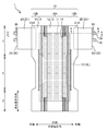
- FIG. 1 is a plan view of the developed absorbent article 1 as seen from the skin side.
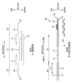
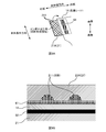
- 2A is an exploded explanatory view taken along the line AA in FIG.
- FIG. 2B is an enlarged explanatory view taken along the line BB in FIG.
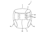
- FIG. 3 is an explanatory diagram of the absorbent article 1 in a worn state.
- 4A and 4B are explanatory diagrams of the fastening tape 30 before unfolding.
- FIG. 4C is an explanatory diagram illustrating a part of the fastening tape 30 in the same state as FIG.
- FIG. 5A is an explanatory diagram of a fold line portion of the side flap 20.
- FIG. 5B is an explanatory diagram of the absorbent article 1 in a state where the side flaps 20 are folded and temporarily fixed (temporarily fixed state).
- FIG. 5C is an enlarged explanatory view of the CC section of FIG. 5B.
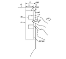
- FIG. 6 is an explanatory diagram of a state during the flap unfolding operation.
- FIG. 7A is a transmission plan view of the adhesive application range of the first temporary fixing part 51.
- FIG. 7B is a transmission plan view of the adhesive application range of the second temporary fixing portion 52.
- 8A to 8C are explanatory diagrams of the joining process of the side flap sheet 21.
- FIG. FIG. 9A is an explanatory diagram of a recess formation region of the base end region 21A.
- FIG. 9B is an enlarged cross-sectional view of the bonding surface in the recess formation region.
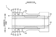
- FIG. 10 is an explanatory diagram of the main body fold line portion 43 when the absorbent article 1 is packaged.
- FIG. 11A is an explanatory diagram of a main body fold line portion 43 of a modification.
- FIG. 11B is an explanatory diagram of folding of the side flap 20 by the main body folding line portion 43 of the modification.
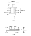
- FIG. 12A is an explanatory diagram of a temporarily fixed state in the second embodiment.
- FIG. 12B is an enlarged explanatory view of the DD cross section of FIG. 12A.
- the base end region there is a recess forming region in which a recess is formed, the skin side sheet and the flap sheet are joined in the recess forming region, and the skin side surface of the folded back side flap.
- the absorbent article is characterized in that the skin side surface of the main body part is temporarily fixed by a temporary fixing part formed in a region overlapping with the concave portion forming region in the thickness direction. According to such an absorbent article, it is possible to prompt the operator to perform a sufficient flap unfolding operation.
- the skin side sheet has less basis weight than the flap sheet. This is particularly effective in such a case.
- the temporary fixing portion is formed along a longitudinal direction of the main body with a predetermined width, and is arranged so that the concave portion formed in a line crosses the temporary fixing portion when viewed from the thickness direction. It is desirable. Thereby, the peeling origin of a temporary fix part can be formed so that a temporary fix part may be crossed.
- the side flap is folded by a first fold line portion on the side of the flap tip and a second fold line portion on the side of the main body, and the side flap is folded by the second fold line portion.
- the skin-side surface and the skin-side surface of the main body portion are temporarily fixed by the temporary fixing portion, and the non-skin-side surfaces of the side flaps folded back by the first folding line portion are the temporary surfaces. It is desirable to be temporarily fixed by a temporary fixing part different from the fixing part. Thereby, the operation
- the bonding force of the another temporary fixing portion is stronger than the bonding force of the temporary fixing portion that temporarily fixes the skin side surface of the side flap and the skin side surface of the main body portion. As a result, the operator can be encouraged to perform a sufficient flap unfolding operation.
- the main body fold line part along the main body longitudinal direction, the main body part is further folded from the state where the side flaps are folded, and in the state where the side flaps are temporarily fixed while unfolding the main body fold line part, It is desirable that the main body fold line portion is located on the inner side in the main body width direction than the fastening tape. Thereby, it becomes difficult to fold the main body fold line portion on the fastening tape.
- the main body fold line portion is preferably located on the inner side in the main body width direction with respect to the first fold line portion. This makes it difficult for the side flaps to be excessively folded.
- the main body fold line portion is located between the first fold line portion and the tape front end portion of the fastening tape. Therefore, it can suppress that the tape front-end
- At least two fastening tapes are provided at the flap front ends of the side flaps, and the fastening tapes are folded by fixing the fastening surfaces of the fastening tapes to the side flaps. It is desirable that a temporary fixing portion for folding is formed along the longitudinal direction of the body on the outer side of the folded two fastening tapes in the longitudinal direction of the body. This makes it easier to put a finger in the area between the two fastening tapes when the flap tip is gripped and the flap unfolding operation is performed.
- an absorbent article comprising: a skin side sheet on the skin side constituting the main body part; and a flap sheet in which a base end region is joined to the skin side sheet and a region outside the base end region forms a side flap.
- a recessed portion forming region having a recessed portion in the proximal end region of the flap sheet; and a skin side surface of the folded side flap and a skin side surface of the main body portion.
- the manufacturing method of becomes clear. According to such a method for manufacturing an absorbent article, it is possible to manufacture an absorbent article that can prompt the operator to perform a sufficient flap unfolding operation.
- FIG. 1 is a plan view of the developed absorbent article 1 as seen from the skin side.
- 2A is an exploded explanatory view taken along the line AA in FIG.
- FIG. 2B is an enlarged explanatory view taken along the line BB in FIG.
- FIG. 3 is an explanatory diagram of the absorbent article 1 in a worn state.
- the side that should be positioned on the skin side of the wearer may be referred to as “skin side”, and the side that should be positioned on the non-skin side of the wearer may be referred to as “non-skin side”.
- the longitudinal direction of the main body 10 of the elongated absorbent article 1 may be referred to as “main body longitudinal direction”, and the width direction of the main body 10 may be referred to as “main body width direction”.
- the center side of the absorbent article 1 may be referred to as “inside” and the opposite side may be referred to as “outside”.
- each sheet may be referred to as a “base end portion”, and an outer end portion of each sheet may be referred to as a “leading end portion”.
- a direction orthogonal to the longitudinal direction of the main body and the width direction of the main body may be referred to as a “thickness direction”.
- the side of the top sheet 12 when viewed from the absorbent core 11 may be referred to as “front side”, and the opposite side may be referred to as “back side”.
- the “skin side” becomes “front side”, but as described later, the “non-skin side” may become “front side” when the sheet is folded. .
- the absorbent article 1 is an article that absorbs and retains the excretion fluid (for example, urine) of the wearer.
- the absorbent article 1 of this embodiment is a disposable diaper for adults.
- the absorbent article 1 may be a baby diaper or a sanitary napkin.
- the absorbent article 1 has a front part 3, a crotch part 5, and a rear part 7, as shown in FIG.
- the front part 3 is a part which will be located in a wearer's front side (abdominal side).
- the rear part 7 is a part which will be located in a wearer's rear side (buttock side, back side).
- the crotch part 5 is a part that is located between the front part 3 and the rear part 7.
- the absorbent article 1 has a main body 10, a side flap 20, and a fastening tape 30. Moreover, the absorbent article of this embodiment is bonded to the skin side sheet
- a region outside the region 21 ⁇ / b> A has a side flap sheet 21 constituting the side flap 20.
- the main body portion 10 is a belt-like portion located in the central portion of the absorbent article 1 in the main body width direction, and is configured along the longitudinal direction across the front portion 3, the crotch portion 5, and the rear portion 7.
- the main body 10 has an absorption region 10A and a wing region 10B.
- the absorption region 10 ⁇ / b> A is a region that absorbs and holds liquid, and is formed at the center of the main body 10.
- the wing region 10B is a region outside the absorption region 10A.
- Side flaps 20 are formed outside the rear portion 7 of the wing region 10B.
- the crotch part 5 of the wing region 10B is provided with a stretchable part 15 (see FIG. 1) that constitutes a leg gather LG (see FIG. 3) that prevents leakage of urine and feces from the wearer's legs.
- the main body 10 has an absorbent core 11, a top sheet 12, and a back sheet 13.
- the absorptive core 11 is a member that absorbs and holds liquid (excretion fluid).
- the top sheet 12 is a liquid-permeable sheet member disposed on the skin side of the absorbent core 11.
- the back sheet 13 is a liquid-impermeable sheet member disposed on the non-skin side of the absorbent core 11.
- the main body 10 has a pair of side gather sheets 14.
- the pair of side gather sheets 14 are sheets that constitute a three-dimensional gather that stands on the top sheet 12.
- the outer end portion of the side gather sheet 14 is joined so that it cannot stand up at a joint portion along the longitudinal direction of the main body.
- the inner end portion of the side gather sheet 14 is given a contraction force in the longitudinal direction by rubber thread (not shown) or the like, and stands up on the skin side in the thickness direction by this contraction force and functions as a three-dimensional gather.
- the side flap 20 is a part formed to protrude outward from the main body 10.
- the side flap 20 is comprised with the side flap sheet
- the base end region 21A on the inner side of the side flap sheet 21 is joined between the back sheet 13 and the side gather sheet 14, and the region outside the base end region 21A of the side flap sheet 21 is connected to the side flap 20. It is composed.
- the side gather sheet 14 since the side gather sheet 14 is joined on the skin side of the base end region 21 ⁇ / b> A of the side flap sheet 21, the side gather sheet 14 becomes the “skin side sheet”.
- the top sheet 12 may be joined on the skin side of the proximal end region 21A of the side flap sheet 21, and in this case, the top sheet 12 becomes the “skin side sheet”. Further, the non-skin side of the base end region 21 ⁇ / b> A of the side flap sheet 21 may be joined to another sheet instead of the back sheet 13.
- Fastening tape 30 is a tape-shaped portion provided at the flap tip portion 23 of the side flap 20. As shown in FIG. 1, the fastening tape 30 is unfolded so as to protrude outward from the flap tip 23 during use. Further, as shown in FIG. 3, the fastening tape 30 is used by being fastened to the target area 3 ⁇ / b> A of the front part 3 (non-skin-side fastening area of the back sheet 13) when worn.
- a fastening surface 34 (joint surface) is formed on the skin side surface of the fastening tape 30.
- the fixing surface 34 is configured by applying an adhesive, but may be configured by a hook sheet that is caught on the target area 3 ⁇ / b> A of the front portion 3.
- the fastening tape 30 is configured by two base material sheets (a first base material sheet 31 and a second base material sheet 32) bonded together.
- a fastening surface 34 is formed on the skin-side surface of the first base sheet 31 disposed on the skin side.
- the two base sheets constituting the fastening tape 30 can be divided into a base end region 33X, an intermediate region 33A, a fastening region 33B, and a front end region 33C.
- the proximal end region 33X is a region joined to the side flap 20.
- the distal end portion of the side flap sheet 21 is sandwiched and joined between the first base sheet 31 and the second base sheet 32.
- the base end region 33X belongs to the side flap 20, and a part of the first base sheet 31 (base end region 33X) is disposed on the skin side surface of the side flap 20, and the non-skin side of the side flap 20 is located on the non-skin side.
- a part (base end region 33X) of the second base sheet 32 is disposed on the surface.
- the regions other than the base end region 33X are regions that are projected outward from the flap distal end portion 23 of the side flap 20 during use.
- the intermediate region 33A is a region between the proximal end region 33X and the fastening region 33B.
- the fastening region 33B is a region where the fastening surface 34 is provided.
- the tip region 33C is a region closer to the tape tip 35 than the fastening region 33B.
- the distal end region 33 ⁇ / b> C is configured as a non-stick surface and functions as a “knob” that is pinched with a finger when the fastening tape 30 is used (when deployed or worn). In order to improve the visibility of the portion where the fastening tape 30 is picked, the tip region 33C may be colored.
- FIG. 4A and 4B are explanatory diagrams of the fastening tape 30 before unfolding.
- FIG. 4A is a plan view of the fastening tape 30 before unfolding.
- FIG. 4B is a cross-sectional view of the fastening tape 30 before unfolding.
- the fastening tape 30 before unfolding is folded with the fastening surface 34 fastened to the skin side surface of the side flap 20.
- the fastening surface 34 to which the adhesive is applied is fastened to the nonwoven fabric (side flap sheet 21), fibers adhere to the developed fastening surface 34, and the fastening property of the fastening surface 34 is improved.
- the fastening surface 34 to which the adhesive is applied is fastened to the first base sheet 31 on the side flap 20.
- the tape tip portion 35 of the fastening tape 30 (the tip portion of the tip region 33 ⁇ / b> C) is folded so as to protrude inward from the first base sheet 31.
- the fold line portion for folding the fastening tape 30 may be referred to as a “tape fold line portion 36”.
- the tape fold line portion 36 is formed in the intermediate region 33A (or the boundary portion between the base end region 33X and the intermediate region 33A).
- FIG. 4C is an explanatory diagram illustrating some of the components of the fastening tape 30 in the same state as FIG. 4B with the components omitted.
- the fastening tape 30 may be illustrated without the proximal end region 33X.
- the fastening tape 30 may be illustrated as one sheet as shown in FIG. 4C.
- FIG. 5A is an explanatory diagram of a fold line portion of the side flap 20.
- FIG. 5B is an explanatory diagram of the absorbent article 1 in a state where the side flaps 20 are folded and temporarily fixed (temporarily fixed state).
- FIG. 5C is an enlarged explanatory view of the CC section of FIG. 5B. As illustrated, the side flaps 20 of the absorbent article 1 are temporarily fixed in a folded state. Thereby, when making a wearer wear the absorbent article 1, it becomes easy to lay the rear part 7 of the absorbent article 1 under a wearer.
- the side flap 20 is folded by a first fold line portion 41 and a second fold line portion 42.
- the first fold line portion 41 is a fold line portion of the side flap 20 closest to the flap tip portion 23.
- the second fold line portion 42 is a fold line portion on the most proximal end side of the side flap 20.
- the first fold line portion 41 becomes a mountain fold-like fold line portion
- the second fold line portion 42 becomes a valley fold-like fold line portion (see FIG. 5A). . That is, the side flaps 20 are folded back alternately to be folded into a bellows shape.
- a region between the first fold line portion 41 and the flap tip portion 23 in the side flap 20 may be referred to as an “outer region 20B”. Further, a region (here, a region between the first fold line portion 41 and the second fold line portion 42) that faces the skin side surface of the main body 10 when folded is referred to as an “inner region 20A”. Sometimes.
- the first fold line portion 41 and the second fold line portion 42 are fold line portions for folding the side flap 20.
- the first fold line portion 41 and the second fold line portion 42 become fold line portions along the main body longitudinal direction.
- the side flap sheet 21 constituting the side flap 20 has a thickness, a region to be bent when the side flap 20 is bent has a width, but here, the “fold line portion” is bent. Refers to the center position of the area.
- the side flap 20 is temporarily fixed in a folded state.
- “temporarily fastened” means that the material is bonded to such an extent that it cannot be peeled off during manufacture and transport, but can be peeled off by a human hand during use.
- the side flap 20 is temporarily fixed by a first temporary fixing part 51 and a second temporary fixing part 52.
- the first temporary fixing part 51 is a part that temporarily fixes the non-skin side surfaces of the side flaps 20 folded back by the first folding line part 41.
- the second temporary fixing part 52 is a part that temporarily fixes the skin side surface of the side flap 20 folded back by the second temporary fixing part 52 and the skin side surface of the main body part 10.
- the first temporary fixing part 51 and the second temporary fixing part 52 are formed by applying an adhesive.
- the first temporary fixing portion 51 temporarily fixes the non-skin side surfaces of the side flaps 20 folded back by the first folding line portion 41
- the second temporary fixing portion. 52 temporarily fixes the skin-side surface of the side flap 20 and the skin-side surface of the main body 10 that are folded back by the second fold line portion 42.
- the flap front end portion 23 is positioned outside the first fold line portion 41 when the side flap 20 is temporarily fixed (temporarily fixed state).
- the outer region 20B of the side flap 20 (the region between the first fold line portion 41 and the flap tip portion 23) is disposed on the front side with the flap tip portion 23 facing outside. become.
- work overlap expansion
- the flap front end portion 23 is on the inner side.
- the flap front end 23 is on the lower side of the wearer.
- the flap tip part 23 can be easily pulled out, and the flap deployment work is facilitated.
- the fastening tape 30 is folded with the fastening surface 34 fastened to the skin side surface of the side flap 20.
- the fastening tape 30 is folded in this way and the flap front end portion 23 is positioned outside the first fold line portion 41, the fastening tape 30 is disposed on the front side of the side flap 20.
- work tape expansion
- the fastening tape 30 becomes easy.
- the fastening tape 30 is arranged on the front side of the side flap 20, the tape leading end portion 35 of the fastening tape 30 easily comes into contact with the wearer's skin. Therefore, in the present embodiment, as shown in FIGS.
- the tape front end portion 35 of the fastening tape 30 is more than the first fold line portion 41 in a state where the side flap 20 is temporarily fixed (temporarily fixed state). Located on the outside. Thereby, since the tape front-end
- FIG. 6 is an explanatory diagram of the state during the flap unfolding operation.
- an interval L1 between the first fold line portion 41 and the second fold line portion 42 and an interval L2 between the flap tip portion 23 and the first fold line portion 41 are shown.
- the interval L1 is wider than the interval L2.
- first temporary fixing part 51 and the second temporary fixing part 52 are formed so that the bonding force of the first temporary fixing part 51 is stronger than the bonding force of the second temporary fixing part 52. For this reason, when the flap leading end portion 23 is picked and the flap unfolding operation is performed (see FIG. 6), the second temporary fixing portion 52 having a weak bonding force is first peeled off, and the first temporary fixing is peeled after the second temporary fastening portion 52 is peeled off. The part 51 will peel off. Since the operator who performs the flap unfolding operation may end the flap unfolding operation when the first temporary locking portion 51 on the side close to himself / herself is peeled off, it is more likely than the second temporary locking portion 52 during the flap unfolding operation.
- the flap unfolding operation is finished with the second temporary fixing part 52 not peeled off, and the fastening tape 30 is securely fixed to the target area 3A (see FIG. 3). It cannot be put on, which may lead to leakage and a feeling of strangeness when worn.
- the second temporary fixing part 52 is already peeled off. Can be encouraged.
- the joining force can be measured with a tensile testing machine (manufactured by Instron Japan Ltd., model 5543).
- the bonding force is measured as follows. First, the test piece of the side flap 20 is fixed to the upper fixing part and the lower fixing part of the tensile tester.
- the test piece fixed to the upper fixing part and the lower fixing part has a width of 10 mm.
- a joint surface corresponding to the first temporary fixing part 51 (or the second temporary fixing part 52) is formed between the test piece fixed to the upper fixing part and the test piece fixed to the lower fixing part. That is, a joining surface corresponding to the first temporary fixing part 51 (or the second temporary fixing part 52) is formed at a substantially intermediate position between the upper fixing part and the lower fixing part.
- the relative displacement rate between the upper fixed portion and the lower fixed portion of the tensile tester is set to 100 mm / min, and the maximum load point while peeling the bonded portion is defined as the bonding force (adhesive strength).
- the joining force of the first temporary fixing part 51 is, for example, in the range of 2 to 10 N / 25 mm 2 , and more preferably in the range of 2 to 7 N / 25 mm 2 .
- the joining force of the second temporary fixing part 52 is, for example, in the range of 0 to 4 N / 25 mm 2 . In such a numerical range, it is desirable that the bonding force of the first temporary fixing part 51 is stronger than the bonding force of the second temporary fixing part 52.
- FIG. 7A is a transmission plan view of the adhesive application range of the first temporary fixing part 51.
- the side flap 20 and the fastening tape 30 are permeate
- the adhesive of the first temporary fixing portion 51 is applied in a zigzag manner along the longitudinal direction of the main body while reciprocating the linear adhesive with a width of 6.25 mm in the main body width direction.
- the first temporary fixing part 51 is formed by coating the hot melt adhesive in a non-contact manner. After the hot melt adhesive was applied to the non-skin side surface of the inner region 20 ⁇ / b> A of the side flap 20, the side flap 20 was folded at the first fold line portion 41 and folded back by the first fold line portion 41. The non-skin side surfaces of the side flaps 20 are temporarily fixed by the first temporary fixing portions 51.
- the adhesive of the first temporary fixing part 51 is formed so that the first temporary fixing part 51 is formed along the main body longitudinal direction outside the two fastening tapes 30 in the main body longitudinal direction. It is applied to the non-skin side surface of the side flap 20.
- the first temporary fixing part 51 is not formed between the two fastening tapes 30 folded, when the operator performs the flap deployment work by picking the flap tip 23 as shown in FIG. It becomes easy to put a finger in the area between the two fastening tapes 30.
- stop part 51 is not apply
- the fastening tape 30 uses a material having rigidity higher than that of the side flaps 20, the operator can easily slide his / her finger under the fastening tape 30, and the flaps are unfolded by grasping the flap tip 23. It becomes easier to work.
- a part of the second base material sheet 32 base end region 33 ⁇ / b> X
- the first overlapped position with the fastening tape 30 since a part of the second base material sheet 32 (base end region 33 ⁇ / b> X) is disposed on the non-skin side surface of the side flap 20, the first overlapped position with the fastening tape 30.
- FIG. 7B is a transmission plan view of the adhesive application range of the second temporary fixing portion 52. Also in FIG. 7B, the side flap 20 and the fastening tape 30 are permeated to show the adhesive application range.
- stop part 52 is apply
- the second temporary fixing portion 52 is formed by applying a hot melt adhesive in a non-contact manner. After the hot melt adhesive is applied to the skin side surface of the main body 10, the side flap 20 is folded at the second fold line portion 42, and the skin of the side flap 20 folded back by the second temporary fixing portion 52. The side surface and the skin side surface of the main body 10 are temporarily fixed by the second temporary fixing portion 52.
- the linear adhesive applied to the first temporary fixing part 51 is thicker than the fine linear adhesive applied to the second temporary fixing part 52.
- the amount of the adhesive per unit area in the first temporary fixing part 51 is larger than the amount of the adhesive per unit area in the second temporary fixing part 52.
- the first temporary fixing portion 51 and the second temporary fixing portion 52 are formed so that the bonding force of the first temporary fixing portion 51 is stronger than the bonding force of the second temporary fixing portion 52.
- the 2nd temporary fix part 52 with weak joining force becomes easy to peel ahead of the 1st temporary fix part 51 at the time of flap expansion
- a dispenser that discharges the adhesive of the first temporary fixing part 51 (hereinafter referred to as a first dispenser) and a dispenser that discharges the adhesive of the second temporary fixing part 52 (hereinafter referred to as the second dispenser) are The same amount of adhesive is discharged per unit time. For this reason, the amount of the adhesive applied to the first temporary fixing portion 51 and the amount of the adhesive applied to the second temporary fixing portion 52 are substantially the same.
- the width of the first dispenser reciprocating in the body width direction is narrower than the second dispenser (here 6.25 mm) and the application area of the first temporary fixing part 51 is narrower than the second temporary fixing part 52, the first dispenser The amount of the adhesive per unit area in the first temporary fixing part 51 is larger than the amount of the adhesive per unit area in the second temporary fixing part 52.
- the bonding force of the first temporary fixing part 51 is greater than the bonding force of the second temporary fixing part 52. It is possible to form the 1st temporary fix part 51 and the 2nd temporary fix part 52 so that it may become strong.
- the sheet to which the adhesive is applied is processed in advance (for example, embossing).
- embossing it is possible to make the joining force of the first temporary fixing part 51 and the second temporary fixing part 52 different.
- the adhesive may be applied along the longitudinal direction of the main body. May be applied continuously. Further, the adhesive may be applied by contact instead of non-contact.
- FIG. 8A to 8C are explanatory diagrams of the joining process of the side flap sheet 21.
- the fastening tape 30 is attached to the flap tip 23 of the side flap sheet 21, and the fastening surface 34 is attached to the skin side surface of the side flap 20. Then, the fastening tape 30 is folded. Further, before the side flap sheet 21 is joined to the side gather sheet 14 (skin side sheet), the adhesive of the first temporary fixing portion 51 is applied, and the side flap sheet 21 is folded back at the first fold line portion 41. The non-skin-side surfaces of the side flaps 20 folded back by the first fold line portion 41 are temporarily fixed by the first temporary fixing portion 51.
- the side flap sheet 21 temporarily fixed by the first temporary fixing part 51 is applied to the front side of the side gather sheet 14 by the second temporary fixing part 52 after the adhesive of the second temporary fixing part 52 is applied. Temporarily fixed at (skin side).
- the second fold line portion 42 is not formed, and the proximal end region 21A of the side flap sheet 21 is located on the outer side in the main body width direction with respect to the side gather sheet 14.
- an adhesive 61 is applied to the back side (non-skin side) surface of the side gather sheet 14.
- the adhesive 61 is an adhesive applied for joining the side flap sheet 21 and the side gather sheet 14 (skin side sheet).
- the side flap sheet 21 is folded back at the second fold line portion 42, and the base end region 21 ⁇ / b> A of the side flap sheet 21 is bonded to the side gather sheet 14.
- the base end region 21A of the side flap sheet 21 folded back by the second fold line portion 42 is pressurized from the back side toward the side gather sheet 14, thereby causing the side flap sheet 21 to be It will be joined to the gather sheet 14 (skin side sheet).
- the base sheet 21A is joined between the back sheet 13 and the side gather sheet 14 by joining the back sheet 13 to the back side. become.
- the side flap sheet 21 is thick and has high rigidity because the side flap sheet 21 is pulled when the flap unfolding operation or the fastening tape 30 is fixed to the target area 3A (see FIG. 3).
- the side gather sheet 14 which is a skin side sheet is a member in contact with the wearer's skin, the sheet is thinner and softer than the side flap sheet 21.
- the side flap sheet 21 is 50 g / m 2
- the basis weight of the side gather sheet 14 is 15 g / m 2
- the side gather sheet 14 (skin side sheet) is more than the side flap sheet 21. Also become thinner.
- the side gather sheet 14 is lower in rigidity than the side flap sheet 21. For this reason, when the side flap sheet 21 is pressed toward the side gather sheet 14 with the adhesive 61 applied as shown in FIG. 8C, the adhesive 61 penetrates into the thin side gather sheet 14 and adheres. The agent 61 may pass through the side gather sheet 14. Further, as shown in FIG. 8C, when the application region of the adhesive 61 and the second temporary fixing portion 52 overlap in the thickness direction, the second temporary fixing portion is bonded by the adhesive 61 that has passed through the gather sheet 14. There is a possibility that the bonding force of 52 is strengthened. As a result, there is a possibility that the operator may finish the flap unfolding work while the second temporary fixing part 52 is not sufficiently peeled off.
- FIG. 9A is an explanatory diagram of a recess forming region of the base end region 21A.
- FIG. 9A shows a state during the process shown in FIG. 8B.
- the surface of the skin side of the base end region 21A of the side flap sheet 21 is provided with a recess forming region by embossing.
- the side flap sheet 21 is embossed by being sandwiched between an embossed roller having unevenness and a flat roller.
- the sheet surface on the embossing roller side becomes an embossed surface, and the opposite sheet surface becomes a non-embossed surface.
- the skin side surface of the side flap sheet 21 is an embossed surface, and the opposite side is a non-embossed surface.
- the convex portion of the embossing roller joins the fibers of the side flap sheet 21 (nonwoven fabric) with heat, the nonwoven fabric is formed into a film, and this filmed portion becomes the concave portion 211 on the embossed surface.
- the concave portion 211 is formed on the embossed surface and the concave and convex portions are not formed on the non-embossed surface on the opposite side, the embossed surface and the non-embossed surface Can be identified.
- embossing is applied to a thin sheet (nonwoven fabric), irregularities may also be visually recognized on the non-embossed surface.
- the concave portion on the embossed surface is more than the concave portion on the non-embossed surface. Since it becomes large, the embossed surface and the non-embossed surface can be distinguished from the size relationship of the concave portion 211 (the large surface of the concave portion 211 is the embossed surface).
- the reason why the size of the recess differs between the embossed surface and the non-embossed surface is that the size of the top of the convex portion of the embossing roller is filmed on the non-embossed surface and is visually recognized as a recess. This is because the convex portion and its periphery are formed into a film on the processed surface and visually recognized as the concave portion 211.
- the skin-side embossed surface of the base end region 21 ⁇ / b> A of the side flap sheet 21 becomes a recess forming region in which the recess 211 is formed.
- the adhesive 61 is applied to a region facing the recess forming region when the side flap sheet 21 is folded back at the second fold line portion 42.
- the recess forming region is a region wider than the application region of the adhesive 61 and covers the application region of the adhesive 61 when the side flap sheet 21 is folded back at the second fold line portion 42.
- FIG. 9B is an enlarged cross-sectional view of the bonding surface in the recess formation region.
- FIG. 9B shows a state during the process shown in FIG. 8C.
- the adhesive 61 is sandwiched between the side gather sheet 14 (skin side sheet) and the recessed portion forming region of the side flap sheet 21, whereby the side gather sheet 14 and the side flap sheet 21 are recessed by the adhesive 61. It will be joined in the region.
- the side gather sheet 14 (skin side sheet) and the side flap sheet 21 are equivalent to the amount that has entered the concave portion 211.
- the amount of the adhesive 61 sandwiched between the two decreases. For this reason, in this embodiment, the quantity of the adhesive agent 61 which permeate
- the second temporary fixing portion 52 overlaps with the concave portion formation region (application region of the adhesive 61) in the thickness direction, and thus the adhesive that transmits the side gather sheet 14. By reducing the amount of the agent 61, it is possible to suppress an increase in the bonding force of the second temporary fixing portion 52.
- the recess forming area is provided by embossing, the recess forming area may not be formed by embossing. Even if it is not embossing, if the concave portion 211 is formed on the skin side surface of the base end region 21A of the side flap sheet 21, the adhesive 61 is taken into the concave portion 211, and therefore there is no concave portion 211. In comparison, it is possible to reduce the amount of the adhesive 61 that passes through the side gather sheet 14. However, when the side flap sheet 21 is embossed, the rigidity of the side flap sheet 21 can be increased, so that the proximal end region 21A can be stably joined to the side gather sheet 14 (skin side sheet). Further effects can be obtained.
- the side gather sheet 14 (skin side sheet) has less basis weight than the side flap sheet 21.
- the adhesive agent 61 is easy to permeate
- seat 14 skin side sheet
- the side flap sheet 21 in which the recessed part 211 is formed becomes thicker than the side gather sheet 14, the deep recessed part 211 can be formed, and the amount of the adhesive 61 taken into the recessed part 211 can be increased.
- the linear concave portion 211 is formed along the longitudinal direction of the main body with the second temporary fixing portion 52 (25 mm width). It will be arranged so as to cross the formed second temporary fixing portion 52).
- region with weak joining force area
- the linear recess 211 is arranged so as to cross the second temporary fixing part 52. Sometimes peeling of the second temporary fixing part 52 can be promoted.
- linear concave portions 211 are arranged in a lattice pattern.
- a plurality of linear recesses 211 parallel to the first direction and a plurality of linear recesses 211 parallel to the direction intersecting the first direction form a grid-like recess 211 in the recess formation region.
- the width of one linear recess 211 is, for example, 2 mm.
- the interval between the parallel linear recesses 211 and the recesses 211 is, for example, 20 mm in the main body width direction, and is, for example, 30 mm in the main body longitudinal direction.
- linear concave portions 211 are arranged in a lattice shape, a plurality of linear concave portions are arranged so as to cross the second temporary fixing portion 52, and the linear concave portions 211 are formed from a plurality of directions. Since it arrange
- the arrangement of the linear concave portions 211 is not limited to the lattice shape, and the linear concave portions 211 may be arranged, for example, in a striped pattern. Further, the recess 211 is not limited to a linear shape (groove shape), and the recess 211 may be, for example, a dot shape. Even if it is such a recessed part, the joining force of the 2nd temporary fix
- FIG. 10 is an explanatory diagram of the main body fold line portion 43 when the absorbent article 1 is packaged.
- the absorbent article 1 in the figure is in a state in which the side flap 20 is folded and temporarily fixed while the body fold line portion 43 is expanded.
- the main body 10 (the main body 10 on the inner side in the main body width direction from the side flap 20) is further provided along the main body longitudinal direction from the state in which the side flaps 20 are folded and temporarily fixed. It is folded by the fold line portion 43.
- the absorbent article 1 in a state in which the side flaps 20 are folded and temporarily fixed is folded into three along the longitudinal direction of the main body by the two main body folding lines 43 during packaging (in addition, this Thus, the absorbent article 1 folded into three is further folded into three by a fold line portion along the width direction of the main body, but the description is omitted here.
- the main body folding line 43 is positioned on the inner side in the main body width direction with respect to the fastening tape 30. is doing. If the main body fold line portion 43 is arranged so as to cross the fastening tape 30, the fastening tape 30 is folded when the main body portion 10 is folded by the main body fold line portion 43.
- the tape front end portion 35 rises when the main body fold line portion 43 is unfolded, and the tape front end portion 35 of the fastening tape 30 is The problem that it becomes easy to contact a wearer's skin will arise.
- the main body fold line portion 43 is located on the inner side in the main body width direction with respect to the fastening tape 30, so that the folding folds of the main body fold line portion 43 are not attached to the fastening tape 30.
- the main body folding line portion 43 is more main body than the first folding line portion 41. It is located inside in the width direction. Therefore, when the main body part 10 is folded at the main body fold line part 43, the side flap 20 is not subjected to an excessive folding.
- FIG. 11A is an explanatory diagram of a main body fold line portion 43 of a modified example. Also in the modified example, in a state where the side flap 20 is folded and temporarily fixed while the main body fold line portion 43 is expanded, the main body fold line portion 43 is located on the inner side in the main body width direction with respect to the fastening tape 30. For this reason, even in the modified example, the folding tape of the main body fold line portion 43 is not attached to the fastening tape 30.
- the side fold line portion 43 when the side flap 20 is folded and temporarily fixed while the body fold line portion 43 is unfolded, the body fold line portion 43 is located between the first fold line portion 41 and the tape front end portion 35. Is located. For this reason, in the modified example, the side fold 20 has a folding line of the body fold line portion 43.
- FIG. 11B is an explanatory diagram of the folding of the side flap 20 by the main body folding line 43 according to a modification.
- the side flap 20 has a valley fold-like gusset, when the body fold line portion 43 is unfolded, the inner side of the side flap 20 that is folded and temporarily secured (the first fold line portion 41 side) Stand up.
- the side flap 20 erected by folding gusset covers the tape front end portion 35 of the outer fastening tape 30 from the inner side.
- tip part 35 of the fastening tape 30 contacts a wearer's skin by the side flap 20 which stood up by folding gusset is acquired. Therefore, when the side flap 20 is allowed to be folded by the main body fold line portion 43, the main body fold line portion 43 is positioned between the first fold line portion 41 and the tape front end portion 35. It is desirable.
- the side flap 20 becomes longer in the width direction of the main body.
- the side flap 20 is Z-shaped (bellows-shaped) by the first fold line portion 41 and the second fold line portion 42. It is desirable to fold them alternately.
- the number of folding lines for folding the side flap 20 is not limited to two.
- FIG. 12A is an explanatory diagram of a temporarily fixed state in the second embodiment.
- FIG. 12B is an enlarged explanatory view of the DD cross section of FIG. 12A.
- the side flap 20 is temporarily fixed in a state of being folded at the fold line portion 42. When the side flap 20 in the unfolded state is viewed from the skin side, the fold line portion 42 becomes a valley fold-shaped fold line portion.
- the side flap 20 is temporarily fixed by a first temporary fixing part 51 and a second temporary fixing part 52.
- the first temporary fixing part 51 and the second temporary fixing part 52 temporarily fix the skin side surface of the side flap 20 and the skin side surface of the main body part 10.
- the skin-side surface of the base end region 21A of the side flap sheet 21 is provided with a recess forming region by embossing.
- the side gather sheet 14 and the side flap sheet 21 are joined by the adhesive 61 in the recess forming region.
- seat 14 can be reduced compared with the case where there is no recessed part 211 (when embossing is not performed). Further, as shown in FIG.
- the first temporary fixing portion 51 is formed along the longitudinal direction of the main body of the two folded fastening tapes 30 on the outer side of the longitudinal direction of the main body. (However, in the second embodiment, the adhesive of the first temporary fixing portion 51 is applied to the skin side surface). This makes it easier for the operator to put a finger in the region between the two fastening tapes 30 when the operator performs the flap unfolding operation by grasping the flap tip 23.
- the fastening tape 30 is provided on each of the pair of side flaps 20.
- the number of fastening tapes 30 provided on the side flap 20 is not limited to this, and may be one by one or two or more.
- the fastening tape 30 was comprised with the two base material sheets (The 1st base material sheet 31 and the 2nd base material sheet 32).
- the fastening tape 30 may be composed of one base sheet, or may be composed of two or more base sheets.
- the fastening surface 34 of the fastening tape 30 is made of an adhesive.
- the fastening tape 30 is not made of such an adhesive tape, but may have another structure. .
- the skin-side sheet joined to the skin-side surface of the base end region 21 ⁇ / b> A of the side flap sheet 21 is the side gather sheet 14.
- the skin sheet that is joined to the skin side surface of the base end region 21 ⁇ / b> A of the side flap sheet 21 may be the top sheet 12.
Landscapes
- Health & Medical Sciences (AREA)
- Epidemiology (AREA)
- Engineering & Computer Science (AREA)
- Biomedical Technology (AREA)
- Heart & Thoracic Surgery (AREA)
- Vascular Medicine (AREA)
- Life Sciences & Earth Sciences (AREA)
- Animal Behavior & Ethology (AREA)
- General Health & Medical Sciences (AREA)
- Public Health (AREA)
- Veterinary Medicine (AREA)
- Absorbent Articles And Supports Therefor (AREA)
Abstract
吸収性物品(1)は、本体部(10)を構成する肌側の肌側シート(14)と、基端領域(21A)が肌側シート(14)に接合され基端領域(21A)よりも外側の領域がサイドフラップを構成するフラップシート(21)と、を備える。フラップシート(21)の基端領域(21A)には、凹部(211)の形成された凹部形成領域がある。肌側シート(14)とフラップシート(21)とが凹部形成領域で接合されており、折り返されたサイドフラップの肌側の面と本体部の肌側の面とが、凹部形成領域と厚み方向に重複する領域に形成された仮止部(52)によって仮止めされている。
Description
本発明は、吸収性物品及び吸収性物品の製造方法に関する。
従来からオープンタイプの使い捨ておむつが広く使用されている。このようなオープンタイプの使い捨ておむつでは、サイドフラップにファスニングテープが設けられている。例えば、特許文献1~4には、オープンタイプの使い捨ておむつが開示されている。これらの特許文献に記載のおむつでは、フラップやテープを折り畳むことも記載されている。
サイドフラップが折り畳まれた状態で仮止めされている場合、折り畳まれた状態でサイドフラップの形状が固定されるため、吸収性物品を着用者に着用させ易くなる。但し、サイドフラップが折り畳まれた状態で仮止めされている場合には、使用時にサイドフラップを展開することが必要になる。このとき、折り畳まれたサイドフラップの仮止部が未剥離のままフラップ展開作業を終えてしまうと、ファスニングテープがターゲット領域に届き難くなる。この結果、ファスニングテープをしっかりと止着させることができず、漏れや装着時の違和感につながるおそれがある。なお、この問題は、使い捨ておむつに限らず、サイドフラップやファスニングテープを備える他の吸収性物品においても生じる問題である。
本発明は、十分なフラップ展開作業を作業者に促すことが可能な吸収性物品を提供することを目的とする。
上記目的を達成するための主たる発明は、本体部を構成する肌側の肌側シートと、基端領域が前記肌側シートに接合され、前記基端領域よりも外側の領域がサイドフラップを構成するフラップシートとを備え、前記フラップシートの前記基端領域には、凹部の形成された凹部形成領域があり、前記肌側シートと前記フラップシートとが前記凹部形成領域で接合されており、折り返された前記サイドフラップの肌側の面と前記本体部の肌側の面とが、前記凹部形成領域と厚み方向に重複する領域に形成された仮止部によって仮止めされていることを特徴とする吸収性物品である。
本発明の他の特徴については、本明細書及び添付図面の記載により明らかにする。
本発明によれば、十分なフラップ展開作業を作業者に促すことができる。
本明細書及び添付図面の記載により、少なくとも以下の事項が明らかとなる。
本体部を構成する肌側の肌側シートと、基端領域が前記肌側シートに接合され、前記基端領域よりも外側の領域がサイドフラップを構成するフラップシートとを備え、前記フラップシートの前記基端領域には、凹部の形成された凹部形成領域があり、前記肌側シートと前記フラップシートとが前記凹部形成領域で接合されており、折り返された前記サイドフラップの肌側の面と前記本体部の肌側の面とが、前記凹部形成領域と厚み方向に重複する領域に形成された仮止部によって仮止めされていることを特徴とする吸収性物品が明らかとなる。このような吸収性物品によれば、十分なフラップ展開作業を作業者に促すことができる。
前記肌側シートは、前記フラップシートよりも目付が少ないことが望ましい。このような場合に特に有効である。
前記仮止部は、所定幅で本体長手方向に沿って形成されており、前記厚み方向から見たときに、線状に形成された前記凹部が前記仮止部を横切るように配置されていることが望ましい。これにより、仮止部を横切るように仮止部の剥離起点を形成できる。
前記サイドフラップは、フラップ先端部の側の第1折り線部と、前記本体部の側の第2折り線部によって折り畳まれており、前記第2折り線部によって折り返された前記前記サイドフラップの肌側の面と前記本体部の肌側の面とが、前記仮止部によって仮止めされており、前記第1折り線部によって折り返された前記サイドフラップの非肌側の面同士が前記仮止部とは別の仮止部で仮止めされていることが望ましい。これによりフラップ先端部を外側に引き出してサイドフラップを展開する作業が容易になる。
前記別の仮止部の接合力は、前記前記サイドフラップの肌側の面と前記本体部の肌側の面とを仮止めする前記仮止部の接合力よりも強いことが望ましい。これにより、十分なフラップ展開作業を作業者に促すことができる。
本体長手方向に沿った本体折り線部によって、前記サイドフラップが折り畳まれた状態から更に本体部が折り畳まれており、前記本体折り線部を展開しつつ前記サイドフラップが仮止めされた状態では、前記本体折り線部がファスニングテープよりも本体幅方向内側に位置することが望ましい。これにより、ファスニングテープに本体折り線部の折りグセが付き難くなる。
前記本体折り線部を展開しつつ前記サイドフラップが仮止めされた状態では、前記本体折り線部が前記第1折り線部よりも前記本体幅方向内側に位置することが望ましい。これにより、サイドフラップに余計な折りグセが付き難くなる。
前記本体折り線部を展開しつつ前記サイドフラップが仮止めされた状態では、前記本体折り線部が前記第1折り線部とファスニングテープのテープ先端部との間に位置することが望ましい。これにより、ファスニングテープのテープ先端部が着用者の肌に接触することを抑制できる。
前記サイドフラップのフラップ先端部に少なくとも2つのファスニングテープが設けられており、前記ファスニングテープの止着面を前記サイドフラップに止着させることによって、前記ファスニングテープが折り畳まれており、前記サイドフラップを折り畳むための仮止部が、折り畳まれた2つの前記ファスニングテープの本体長手方向の外側で、本体長手方向に沿って形成されていることが望ましい。これにより、フラップ先端部を摘まんでフラップ展開作業を行う際に、2つのファスニングテープの間の領域に指を入れやすくなる。
本体部を構成する肌側の肌側シートと、基端領域が前記肌側シートに接合され、前記基端領域よりも外側の領域がサイドフラップを構成するフラップシートとを備える吸収性物品の製造方法であって、前記フラップシートの前記基端領域に、凹部を有する凹部形成領域を形成すること、及び、折り返された前記サイドフラップの肌側の面と前記本体部の肌側の面とが、前記凹部形成領域と厚み方向に重複する領域に形成された仮止部によって仮止めされるように、前記肌側シートと前記フラップシートとを前記凹部形成領域で接合することを行う吸収性物品の製造方法が明らかとなる。このような吸収性物品の製造方法によれば、十分なフラップ展開作業を作業者に促すことができる吸収性物品を製造できる。
===第1実施形態===
<吸収性物品1の全体構成>
図1は、展開状態の吸収性物品1を肌側から見た平面図である。図2Aは、図1のA-A断面における分解説明図である。図2Bは、図1のB-B断面における拡大説明図である。図3は、着用状態の吸収性物品1の説明図である。
<吸収性物品1の全体構成>
図1は、展開状態の吸収性物品1を肌側から見た平面図である。図2Aは、図1のA-A断面における分解説明図である。図2Bは、図1のB-B断面における拡大説明図である。図3は、着用状態の吸収性物品1の説明図である。
以下の説明では、着用者の肌側に位置すべき側を「肌側」と呼び、着用者の非肌側に位置すべき側を「非肌側」と呼ぶことがある。
また、図1に示すように、長尺状の吸収性物品1の本体部10の長手方向を「本体長手方向」と呼び、本体部10の幅方向を「本体幅方向」と呼ぶことがある。
本体幅方向において、吸収性物品1の中央側を「内側」と呼び、逆側を「外側」と呼ぶことがある。また、各シートの内側の端部を「基端部」と呼び、各シートの外側の端部を「先端部」と呼ぶことがある。
また、本体長手方向と本体幅方向に直交する方向を「厚み方向」と呼ぶことがある。なお、厚み方向において、吸収性コア11から見てトップシート12の側を「表側」とし、逆側を「裏側」と呼ぶことがある。吸収性物品1を完全に展開させた状態では「肌側」が「表側」になるが、後述するようにシートが折り畳まれた状態では「非肌側」が「表側」になることもあり得る。
また、図1に示すように、長尺状の吸収性物品1の本体部10の長手方向を「本体長手方向」と呼び、本体部10の幅方向を「本体幅方向」と呼ぶことがある。
本体幅方向において、吸収性物品1の中央側を「内側」と呼び、逆側を「外側」と呼ぶことがある。また、各シートの内側の端部を「基端部」と呼び、各シートの外側の端部を「先端部」と呼ぶことがある。
また、本体長手方向と本体幅方向に直交する方向を「厚み方向」と呼ぶことがある。なお、厚み方向において、吸収性コア11から見てトップシート12の側を「表側」とし、逆側を「裏側」と呼ぶことがある。吸収性物品1を完全に展開させた状態では「肌側」が「表側」になるが、後述するようにシートが折り畳まれた状態では「非肌側」が「表側」になることもあり得る。
吸収性物品1は、着用者の排泄液(例えば尿)を吸収し保持する物品である。本実施形態の吸収性物品1は、大人用の使い捨ておむつである。但し、吸収性物品1は、乳幼児用おむつでも良いし、生理用ナプキン等でも良い。
吸収性物品1は、図1に示すように、前部3と、股下部5と、後部7とを有する。前部3は、着用者の前側(腹側)に位置することになる部分である。後部7は、着用者の後側(臀部側、背側)に位置することになる部分である。股下部5は、前部3と後部7との間に位置することになる部分である。
吸収性物品1は、本体部10と、サイドフラップ20と、ファスニングテープ30とを有する。また、本実施形態の吸収性物品は、以下に説明する通り、本体部を構成する肌側のサイドギャザーシート14(肌側シート)と、基端領域21Aが肌側シートに接合され、基端領域21Aよりも外側の領域がサイドフラップ20を構成するサイドフラップシート21とを有している。
本体部10は、吸収性物品1の本体幅方向の中央部に位置する帯状の部位であり、前部3、股下部5及び後部7にわたって長手方向に沿って構成されている。本体部10は、吸収領域10Aとウイング領域10Bとを有する。吸収領域10Aは、液体を吸収し保持する領域であり、本体部10の中央部の形成されている。ウイング領域10Bは、吸収領域10Aの外側の領域である。ウイング領域10Bの後部7の外側にはサイドフラップ20が形成されている。ウイング領域10Bの股下部5には、着用者の脚回りからの尿便漏れを防ぐレッグギャザーLG(図3参照)を構成する伸縮部15(図1参照)が設けられている。
本体部10は、吸収性コア11と、トップシート12と、バックシート13とを有している。吸収性コア11は、液体(排泄液)を吸収し保持する部材である。トップシート12は、吸収性コア11の肌側に配置された液透過性のシート部材である。バックシート13は、吸収性コア11の非肌側に配置された液不透過性のシート部材である。
また、本体部10は、一対のサイドギャザーシート14を有する。一対のサイドギャザーシート14は、トップシート12上に起立する立体ギャザーを構成するシートである。サイドギャザーシート14の外側の端部は、本体長手方向に沿った接合部において起立不能に接合されている。サイドギャザーシート14の内側の端部は、糸ゴム(不図示)等によって長手方向に収縮力が付与されており、この収縮力によって厚さ方向の肌側に起立して立体ギャザーとして機能する。
サイドフラップ20は、本体部10から外側に突出して形成された部位である。サイドフラップ20は、不織布であるサイドフラップシート21で構成されている。サイドフラップシート21の内側の基端領域21Aが、バックシート13とサイドギャザーシート14との間に接合されており、サイドフラップシート21の基端領域21Aよりも外側の領域が、サイドフラップ20を構成している。本実施形態では、サイドフラップシート21の基端領域21Aの肌側で接合されるのはサイドギャザーシート14であるため、サイドギャザーシート14が「肌側シート」となる。但し、サイドフラップシート21の基端領域21Aの肌側でトップシート12が接合されても良く、この場合には、トップシート12が「肌側シート」となる。また、サイドフラップシート21の基端領域21Aの非肌側がバックシート13ではなく他のシートに接合されても良い。
ファスニングテープ30は、サイドフラップ20のフラップ先端部23に設けられたテープ状の部位である。ファスニングテープ30は、図1に示すように、使用時にはフラップ先端部23よりも外側に突出させて展開されることになる。また、ファスニングテープ30は、図3に示すように、着用時には前部3のターゲット領域3A(バックシート13の非肌側の止着領域)に止着させて用いられる。
ファスニングテープ30の肌側の面には止着面34(接合面)が形成されている。止着面34は、ここでは接着剤を塗布して構成されているが、前部3のターゲット領域3Aに引っ掛かるフックシートによって構成しても良い。
ファスニングテープ30は、張り合わせた2枚の基材シート(第1基材シート31及び第2基材シート32)によって構成されている。肌側に配置された第1基材シート31の肌側の面に止着面34が形成されている。
図2Bに示すように、ファスニングテープ30を構成する2枚の基材シートは、基端領域33Xと、中間領域33Aと、止着領域33Bと、先端領域33Cとに区分できる。
図2Bに示すように、ファスニングテープ30を構成する2枚の基材シートは、基端領域33Xと、中間領域33Aと、止着領域33Bと、先端領域33Cとに区分できる。
基端領域33Xは、サイドフラップ20に接合された領域である。基端領域33Xでは、第1基材シート31と第2基材シート32との間にサイドフラップシート21の先端部が挟まれて接合されている。基端領域33Xはサイドフラップ20に属し、サイドフラップ20の肌側の面には第1基材シート31の一部(基端領域33X)が配置されており、サイドフラップ20の非肌側の面には第2基材シート32の一部(基端領域33X)が配置されている。
基端領域33X以外の領域(中間領域33A、止着領域33B及び先端領域33C)は、使用時にサイドフラップ20のフラップ先端部23よりも外側に突出させて展開される領域となる。中間領域33Aは、基端領域33Xと止着領域33Bとの間の領域である。止着領域33Bは、止着面34が設けられた領域である。先端領域33Cは、止着領域33Bよりもテープ先端部35側の領域である。先端領域33Cは、非止着面として構成されており、ファスニングテープ30の使用時(展開時や着用時)に指で摘まむ「つまみ」として機能する。ファスニングテープ30を摘まむ部位の視認性を良くするために、先端領域33Cに着色が施されることもある。
図4A及び図4Bは、展開前のファスニングテープ30の説明図である。図4Aは、展開前のファスニングテープ30の平面図である。図4Bは、展開前のファスニングテープ30の断面図である。図示するように、展開前のファスニングテープ30は、止着面34をサイドフラップ20の肌側の面に止着させて、折り畳まれている。なお、接着剤の塗布された止着面34が不織布(サイドフラップシート21)に一旦止着されると、展開後の止着面34に繊維が付着して止着面34の止着性が低下するため、接着剤の塗布された止着面34は、サイドフラップ20上の第1基材シート31に止着されている。また、先端領域33Cを摘まみやすくするために、ファスニングテープ30のテープ先端部35(先端領域33Cの先端部)が第1基材シート31よりも内側に突出するように折り畳まれている。
ファスニングテープ30を折り畳むための折り線部のことを「テープ折り線部36」と呼ぶことがある。テープ折り線部36は、中間領域33A(又は基端領域33Xと中間領域33Aとの境界部)に形成される。
図4Cは、図4Bと同じ状態のファスニングテープ30の一部の構成要素を省略して図示した説明図である。以下の説明では、図4Cのように、基端領域33Xを省略してファスニングテープ30を図示することがある。また、以下の説明では、図4Cのように、ファスニングテープ30を1枚のシートとして図示することがある。
<サイドフラップ20の折り線部と仮止部について>
図5Aは、サイドフラップ20の折り線部の説明図である。図5Bは、サイドフラップ20を折り畳んで仮止めした状態(仮止め状態)の吸収性物品1の説明図である。図5Cは、図5BのC-C断面の拡大説明図である。図示するように、吸収性物品1のサイドフラップ20は、折り畳まれた状態で仮止めされている。これにより、吸収性物品1を着用者に着用させる際に、吸収性物品1の後部7を着用者の下に敷き込み易くなる。
図5Aは、サイドフラップ20の折り線部の説明図である。図5Bは、サイドフラップ20を折り畳んで仮止めした状態(仮止め状態)の吸収性物品1の説明図である。図5Cは、図5BのC-C断面の拡大説明図である。図示するように、吸収性物品1のサイドフラップ20は、折り畳まれた状態で仮止めされている。これにより、吸収性物品1を着用者に着用させる際に、吸収性物品1の後部7を着用者の下に敷き込み易くなる。
サイドフラップ20は、第1折り線部41と、第2折り線部42とによって折り畳まれている。第1折り線部41は、サイドフラップ20の最もフラップ先端部23の側の折り線部である。第2折り線部42は、サイドフラップ20の最も基端部側の折り線部である。展開状態のサイドフラップ20を肌側から見ると、第1折り線部41は山折り状の折り線部となり、第2折り線部42は谷折り状の折り線部となる(図5A参照)。つまり、サイドフラップ20が互い違いに折り返されることによって、蛇腹状に折り畳まれている。
以下の説明では、サイドフラップ20における第1折り線部41とフラップ先端部23との間の領域を「外側領域20B」と呼ぶことがある。また、折り畳まれたときに本体部10の肌側の面と対向する領域(ここでは、第1折り線部41と第2折り線部42との間の領域)を「内側領域20A」と呼ぶことがある。
第1折り線部41及び第2折り線部42は、サイドフラップ20を折り畳むための折り線部である。本体部10から本体幅方向の外側に突出したサイドフラップ20を折り畳むため、第1折り線部41及び第2折り線部42は、本体長手方向に沿った折り線部となる。なお、サイドフラップ20を構成するサイドフラップシート21には厚みがあるため、サイドフラップ20を折り曲げたときに折り曲がる領域は幅を持つことになるが、ここでは「折り線部」は、折り曲げた領域の中心位置を指す。
サイドフラップ20は、折り畳まれた状態で仮止めされている。なお、「仮止め」とは、製造搬送時等には剥離せず、使用時に人の手で剥離可能な程度に接合されていることを意味する。具体的には、サイドフラップ20は、第1仮止部51と第2仮止部52とによって仮止めされている。第1仮止部51は、第1折り線部41によって折り返されたサイドフラップ20の非肌側の面同士を仮止めする部位である。第2仮止部52は、第2仮止部52によって折り返されたサイドフラップ20の肌側の面と本体部10の肌側の面とを仮止めする部位である。後述するように、第1仮止部51及び第2仮止部52は、接着剤を塗布することによって形成されている。
本実施形態では、図5Cに示すように、第1仮止部51は、第1折り線部41によって折り返されたサイドフラップ20の非肌側の面同士を仮止めし、第2仮止部52は、第2折り線部42によって折り返されたサイドフラップ20の肌側の面と本体部10の肌側の面とを仮止めしている。これにより、第1折り線部41及び第2折り線部42によって蛇腹状に折り畳まれた状態でサイドフラップ20の形状が固定されるため、吸収性物品1の後部7を着用者の下に敷き込み易くなる。
本実施形態では、図5B及び図5Cに示すように、サイドフラップ20が仮止めされた状態(仮止め状態)では、フラップ先端部23が第1折り線部41よりも外側に位置している。これにより、仮止め状態では、サイドフラップ20の外側領域20B(第1折り線部41とフラップ先端部23との間の領域)が、フラップ先端部23を外側にして、表側に配置されることになる。このため、フラップ先端部23を外側に引き出してサイドフラップ20を展開する作業(フラップ展開作業)が容易になる。なお、仮にフラップ先端部23が第1折り線部41よりも内側になるようにサイドフラップ20が折り畳まれていると、フラップ先端部23が内側になっているために、吸収性物品1の後部7を着用者の下に敷き込んだときにフラップ先端部23が着用者の下側になってしまい、この結果、フラップ先端部23を外側に引き出し難くなり、フラップ展開作業が困難になってしまう。これに対し、本実施形態では、吸収性物品1の後部7を着用者の下に敷き込んだ後でも、フラップ先端部23を外側に引き出しやすいため、フラップ展開作業が容易になる。
ところで、既に説明したように、ファスニングテープ30は、止着面34をサイドフラップ20の肌側の面に止着させて折り畳まれている。このようにファスニングテープ30が折り畳まれた状態で、フラップ先端部23が第1折り線部41よりも外側に位置していると、ファスニングテープ30がサイドフラップ20の表側に配置されることになる。このため、本実施形態では、ファスニングテープ30を展開させる作業(テープ展開作業)も容易になる。
その一方、ファスニングテープ30がサイドフラップ20の表側に配置されると、ファスニングテープ30のテープ先端部35が着用者の肌に接触しやすくなる。そこで、本実施形態では、図5B及び図5Cに示すように、サイドフラップ20が仮止めされた状態(仮止め状態)では、ファスニングテープ30のテープ先端部35が第1折り線部41よりも外側に位置している。これにより、仮止め状態で表側に配置されたファスニングテープ30のテープ先端部35は、折り畳まれたサイドフラップ20から内側に突出していないため、着用者の肌に接触しにくくなる。このため、本実施形態では、吸収性物品1の後部7を着用者の下に敷き込むときに、着用者に不快感を与えずに済む。
その一方、ファスニングテープ30がサイドフラップ20の表側に配置されると、ファスニングテープ30のテープ先端部35が着用者の肌に接触しやすくなる。そこで、本実施形態では、図5B及び図5Cに示すように、サイドフラップ20が仮止めされた状態(仮止め状態)では、ファスニングテープ30のテープ先端部35が第1折り線部41よりも外側に位置している。これにより、仮止め状態で表側に配置されたファスニングテープ30のテープ先端部35は、折り畳まれたサイドフラップ20から内側に突出していないため、着用者の肌に接触しにくくなる。このため、本実施形態では、吸収性物品1の後部7を着用者の下に敷き込むときに、着用者に不快感を与えずに済む。
図6は、フラップ展開作業時の様子の説明図である。図中には、第1折り線部41と第2折り線部42との間隔L1と、フラップ先端部23と第1折り線部41との間隔L2が示されている。図6に示す通り、間隔L1が間隔L2よりも広い。これにより、フラップ先端部23と第2折り線部42との間の領域(第2折り線部42で折り返されたサイドフラップ20の表側に露出した非肌側の面)を指で押さえながら、フラップ先端部23を指で摘まむことができるので、フラップ展開作業が容易になる。
更に、第1仮止部51の接合力が第2仮止部52の接合力よりも強くなるように、第1仮止部51及び第2仮止部52が形成されている。このため、フラップ先端部23を摘まんでフラップ展開作業を行うと(図6参照)、まず接合力の弱い第2仮止部52が剥離し、第2仮止部52の剥離後に第1仮止部51が剥離することになる。フラップ展開作業を行う作業者は、自らに近い側の第1仮止部51が剥離した段階でフラップ展開作業を終えてしまうことがあるため、仮にフラップ展開作業時に第2仮止部52よりも先に第1仮止部51が剥離してしまうと、第2仮止部52が未剥離のままフラップ展開作業を終えてしまい、ターゲット領域3A(図3参照)にファスニングテープ30をしっかりと止着させることができず、漏れや装着時の違和感につながるおそれがある。これに対し、本実施形態では、作業者に近い第1仮止部51が剥離した段階では、既に第2仮止部52も剥離が完了した状態であるため、十分なフラップ展開作業を作業者に促すことができる。
接合力は、引張試験機(インストロンジャパンカンパニイリミテッド製、型式 5543)で測定可能である。例えば、接合力は次のように測定する。まず、引張試験機の上部固定部及び下部固定部に、サイドフラップ20の試験片を固定する。上部固定部及び下部固定部に固定する試験片は幅10mmとする。上部固定部に固定する試験片と下部固定部に固定する試験片との間には、第1仮止部51(又は第2仮止部52)に相当する接合面が形成されている。つまり、上部固定部と下部固定部との間の略中間位置に、第1仮止部51(又は第2仮止部52)に相当する接合面が形成されている。引張試験機の上部固定部と下部固定部との相対変位速度を100mm/分に設定し、接合部を剥離している間の最大荷重点を接合力(接着強度)とする。
第1仮止部51の接合力は、例えば2~10N/25mm2の範囲であり、より望ましくは2~7N/25mm2の範囲である。また、第2仮止部52の接合力は、例えば0~4N/25mm2の範囲である。このような数値範囲において、第1仮止部51の接合力が第2仮止部52の接合力よりも強いことが望ましい。
第1仮止部51の接合力は、例えば2~10N/25mm2の範囲であり、より望ましくは2~7N/25mm2の範囲である。また、第2仮止部52の接合力は、例えば0~4N/25mm2の範囲である。このような数値範囲において、第1仮止部51の接合力が第2仮止部52の接合力よりも強いことが望ましい。
図7Aは、第1仮止部51の接着剤の塗布範囲の透過平面図である。図7Aでは、サイドフラップ20及びファスニングテープ30を透過させて、接着剤の塗布範囲を示している。第1仮止部51の接着剤は、線状の接着剤を本体幅方向に6.25mmの幅で往復させつつ、本体長手方向に沿ってジグザグに塗布されている。第1仮止部51は、ホットメルト接着剤を非接触で塗工することによって、形成されている。サイドフラップ20の内側領域20Aの非肌側の面にホットメルト接着剤が塗布された後、第1折り線部41にてサイドフラップ20が折り曲げられて、第1折り線部41によって折り返されたサイドフラップ20の非肌側の面同士が第1仮止部51によって仮止めされることになる。
本実施形態では、第1仮止部51が、折り畳まれた2つのファスニングテープ30の本体長手方向の外側で本体長手方向に沿って形成されるように、第1仮止部51の接着剤がサイドフラップ20の非肌側の面に塗布される。これにより、折り畳まれた2つのファスニングテープ30の間には第1仮止部51が形成されないため、図6に示すように作業者がフラップ先端部23を摘まんでフラップ展開作業を行う際に、2つのファスニングテープ30の間の領域に指を入れやすくなる。また、ファスニングテープ30と重複する位置には第1仮止部51の接着剤が塗布されていないため、指を入れやすい領域が更に広くなる。特にファスニングテープ30がサイドフラップ20よりも剛性の高い素材を使用している場合には、作業者は、ファスニングテープ30の下側に指を滑り込ませ易くなり、フラップ先端部23を摘まんでフラップ展開作業を行いやすくなる。また、図2Bに示すようにサイドフラップ20の非肌側の面に第2基材シート32の一部(基端領域33X)が配置されているため、ファスニングテープ30と重複する位置に第1仮止部51の接着剤が塗布されていないことによって、第2基材シート32に接着剤が付着することを防止でき、さらに使用時に肌に接着材が付着することを防止できる。
図7Bは、第2仮止部52の接着剤の塗布範囲の透過平面図である。図7Bにおいても、サイドフラップ20及びファスニングテープ30を透過させて、接着剤の塗布範囲を示している。第2仮止部52の接着剤は、細線状の接着剤を本体幅方向に25mmの幅で往復させつつ、本体長手方向に沿ってジグザグに塗布されている。第2仮止部52は、ホットメルト接着剤を非接触で塗工することによって、形成されている。本体部10の肌側の面にホットメルト接着剤が塗布された後、第2折り線部42にてサイドフラップ20が折り曲げられて、第2仮止部52によって折り返されたサイドフラップ20の肌側の面と本体部10の肌側の面とが第2仮止部52によって仮止めされることになる。
図7A及び図7Bに示すように、第1仮止部51に塗布される線状の接着剤は、第2仮止部52に塗布される細線状の接着剤よりも太い。このため、第1仮止部51における単位面積当たりの接着剤の量は、第2仮止部52における単位面積当たりの接着剤の量よりも多くなっている。これにより、第1仮止部51の接合力が第2仮止部52の接合力よりも強くなるように、第1仮止部51及び第2仮止部52が形成されている。これにより、フラップ展開作業時に、接合力の弱い第2仮止部52が第1仮止部51よりも先に剥離しやすくなる。
なお、上記の場合は、第1仮止部51の接着剤を吐出するディスペンサ(以下、第1ディスペンサ)と、第2仮止部52の接着剤を吐出するディスペンサ(以下、第2ディスペンサ)は、単位時間当たりに同じ量の接着剤を吐出する。このため、第1仮止部51に塗布される接着剤の量と、第2仮止部52に塗布される接着剤の量は、ほぼ同じ量になる。但し、第1ディスペンサが本体幅方向に往復する幅が第2ディスペンサよりも狭く(ここでは6.25mm)、第1仮止部51の塗布面積が第2仮止部52よりも狭いため、第1仮止部51における単位面積当たりの接着剤の量が、第2仮止部52における単位面積当たりの接着剤の量よりも多くなる。このように、第1仮止部51及び第2仮止部52に塗布される接着剤が同じ量であっても、1仮止部51の接合力が第2仮止部52の接合力よりも強くなるように、第1仮止部51及び第2仮止部52を形成することが可能である。但し、第1仮止部51と第2仮止部52の接着剤の厚さ(目付)を同じにした場合であっても、接着剤を塗布するシートに予め加工(例えばエンボス加工)を行うことによって、第1仮止部51と第2仮止部52の接合力を異ならせることは可能である。
なお、本体長手方向に沿って接着剤を塗布する方法としては、前述のジグザグに塗工するだけでなく、波形や円形を繰り返すパターンで塗布しても良いし、本体長手方向に沿って接着剤を連続的に塗布しても良い。また、接着剤を非接触で塗工するのではなく、接触塗工しても良い。
<サイドフラップシート21の接合とエンボス加工面について>
図8A~図8Cは、サイドフラップシート21の接合工程の説明図である。
図8A~図8Cは、サイドフラップシート21の接合工程の説明図である。
サイドフラップシート21をサイドギャザーシート14(肌側シート)に接合する前に、サイドフラップシート21のフラップ先端部23にファスニングテープ30が取り付けられ、止着面34をサイドフラップ20の肌側の面に止着させてファスニングテープ30が折り畳まれる。また、サイドフラップシート21をサイドギャザーシート14(肌側シート)に接合する前に、第1仮止部51の接着剤が塗布され、サイドフラップシート21が第1折り線部41で折り返されて、第1折り線部41によって折り返されたサイドフラップ20の非肌側の面同士が第1仮止部51によって仮止めされる。
図8Aに示すように、第1仮止部51によって仮止めされたサイドフラップシート21が、第2仮止部52の接着剤の塗布後、第2仮止部52によってサイドギャザーシート14の表側(肌側)で仮止めされる。この段階では、第2折り線部42は形成されておらず、サイドフラップシート21の基端領域21Aがサイドギャザーシート14よりも本体幅方向の外側に位置している。
次に、図8Bに示すように、サイドギャザーシート14の裏側(非肌側)の面に接着剤61が塗布される。接着剤61は、サイドフラップシート21とサイドギャザーシート14(肌側シート)との接合のために塗布された接着剤である。接着剤61の塗布後、サイドフラップシート21が第2折り線部42で折り返されて、サイドフラップシート21の基端領域21Aがサイドギャザーシート14に接着される。
図8Cに示すように、第2折り線部42によって折り返されたサイドフラップシート21の基端領域21Aは、裏側からサイドギャザーシート14に向かって圧力をかけられ、これによりサイドフラップシート21がサイドギャザーシート14(肌側シート)に接合されることになる。この後、サイドフラップシート21とサイドギャザーシート14との接合後、裏側にバックシート13が接合されることによって、基端領域21Aがバックシート13とサイドギャザーシート14との間に接合されることになる。
ところで、サイドフラップシート21は、フラップ展開作業やファスニングテープ30をターゲット領域3A(図3参照)に止着させるときにサイドフラップシート21が引っ張られるため、厚みがあり剛性の高いシートとなる。これに対し、肌側シートであるサイドギャザーシート14は、着用者の肌に接する部材であるため、サイドフラップシート21と比べて薄くて柔らかいシートとなる。具体的には、サイドフラップシート21は50g/m2であるのに対し、サイドギャザーシート14の目付は15g/m2であり、サイドギャザーシート14(肌側シート)は、サイドフラップシート21よりも薄くなる。また、ガーレ法(JIS法)で測定される剛性について、サイドギャザーシート14はサイドフラップシート21よりも剛性が低くなる。
このため、図8Cに示すように接着剤61が塗布された状態でサイドフラップシート21がサイドギャザーシート14に向かって圧力をかけられると、薄いサイドギャザーシート14に接着剤61が浸透し、接着剤61がサイドギャザーシート14を透過するおそれがある。更に、図8Cに示すように、接着剤61の塗布領域と第2仮止部52が厚さ方向に重複している場合には、ギャザーシート14を透過した接着剤61によって第2仮止部52の接合力が強化されてしまうおそれがある。この結果、第2仮止部52の剥離が不十分なまま作業者がフラップ展開作業を終えてしまうおそれがある。
このため、図8Cに示すように接着剤61が塗布された状態でサイドフラップシート21がサイドギャザーシート14に向かって圧力をかけられると、薄いサイドギャザーシート14に接着剤61が浸透し、接着剤61がサイドギャザーシート14を透過するおそれがある。更に、図8Cに示すように、接着剤61の塗布領域と第2仮止部52が厚さ方向に重複している場合には、ギャザーシート14を透過した接着剤61によって第2仮止部52の接合力が強化されてしまうおそれがある。この結果、第2仮止部52の剥離が不十分なまま作業者がフラップ展開作業を終えてしまうおそれがある。
そこで、本実施形態では、サイドフラップシート21にエンボス加工による凹部形成領域を設けることによって、接着剤61がサイドギャザーシート14を透過することを抑制している。以下、この点について説明する。
図9Aは、基端領域21Aの凹部形成領域の説明図である。図9Aは図8Bに示す工程時の様子である。
サイドフラップシート21の基端領域21Aの肌側の面には、エンボス加工によって凹部形成領域が設けられている。サイドフラップシート21(不織布)が凹凸を有するエンボスローラーと平らなローラーとの間に挟まれることによって、サイドフラップシート21にエンボス加工が施されている。エンボスローラー側のシート面がエンボス加工面となり、逆側のシート面が非エンボス加工面となる。ここでは、サイドフラップシート21の肌側の面がエンボス加工面となり、逆側が非エンボス加工面となる。エンボスローラーの凸部がサイドフラップシート21(不織布)の繊維を熱で接合し、不織布がフィルム化されて、このフィルム化された部分がエンボス加工面の凹部211となる。通常、エンボス加工面に凹部211が形成された状態になり、反対側の非エンボス加工面には凹凸が形成されない状態になるため、表面の凹部211の有無からエンボス加工面と非エンボス加工面とを識別可能である。薄いシート(不織布)にエンボス加工を施した場合には、非エンボス加工面にも凹凸が視認されることもあるが、この場合には、エンボス加工面の凹部が非エンボス加工面の凹部よりも大きくなるため、凹部211の大小関係からエンボス加工面と非エンボス加工面とを識別可能である(凹部211の大きい面がエンボス加工面である)。エンボス加工面と非エンボス加工面とで凹部の大きさが異なる理由は、非エンボス加工面ではエンボスローラーの凸部の頂部の大きさがフィルム化されて凹部として視認されるのに対して、エンボス加工面では凸部とその周囲がフィルム化されて凹部211として視認されるためである。
サイドフラップシート21の基端領域21Aの肌側のエンボス加工面は、凹部211の形成された凹部形成領域となる。接着剤61は、サイドフラップシート21を第2折り線部42で折り返したときに凹部形成領域と対向する領域に塗布される。言い換えると、凹部形成領域は、接着剤61の塗布領域よりも広い領域であり、サイドフラップシート21を第2折り線部42で折り返したときに接着剤61の塗布領域を覆う領域である。
図9Bは、凹部形成領域における接着面の拡大断面図である。図9Bは図8Cに示す工程時の様子である。
接着剤61は、サイドギャザーシート14(肌側シート)と、サイドフラップシート21の凹部形成領域との間に挟まれ、これにより、サイドギャザーシート14とサイドフラップシート21が接着剤61により凹部形成領域で接合されることになる。このとき、図9Bに示すように、接着剤61が凹部形成領域の凹部211の内部に取り込まれるため、凹部211に入り込んだ分だけ、サイドギャザーシート14(肌側シート)とサイドフラップシート21との間に挟み込まれる接着剤61の量が減少する。このため、本実施形態では、凹部211が無い場合(エンボス加工を施さない場合)と比べて、サイドギャザーシート14を透過する接着剤61の量を軽減させることができる。また、図9Bに示すように、本実施形態では第2仮止部52が凹部形成領域(接着剤61の塗布領域)と厚さ方向に重複しているため、サイドギャザーシート14を透過する接着剤61の量を軽減させることによって、第2仮止部52の接合力が強化されてしまうことを抑制できるという効果が得られる。
接着剤61は、サイドギャザーシート14(肌側シート)と、サイドフラップシート21の凹部形成領域との間に挟まれ、これにより、サイドギャザーシート14とサイドフラップシート21が接着剤61により凹部形成領域で接合されることになる。このとき、図9Bに示すように、接着剤61が凹部形成領域の凹部211の内部に取り込まれるため、凹部211に入り込んだ分だけ、サイドギャザーシート14(肌側シート)とサイドフラップシート21との間に挟み込まれる接着剤61の量が減少する。このため、本実施形態では、凹部211が無い場合(エンボス加工を施さない場合)と比べて、サイドギャザーシート14を透過する接着剤61の量を軽減させることができる。また、図9Bに示すように、本実施形態では第2仮止部52が凹部形成領域(接着剤61の塗布領域)と厚さ方向に重複しているため、サイドギャザーシート14を透過する接着剤61の量を軽減させることによって、第2仮止部52の接合力が強化されてしまうことを抑制できるという効果が得られる。
エンボス加工を施すことによって凹部形成領域が設けられているが、凹部形成領域は、エンボス加工によるものでなくても良い。エンボス加工ではなくても、サイドフラップシート21の基端領域21Aの肌側の面に凹部211が形成されていれば、接着剤61が凹部211の内部に取り込まれるため、凹部211が無い場合と比べてサイドギャザーシート14を透過する接着剤61の量を軽減させることが可能である。但し、サイドフラップシート21にエンボス加工を施した場合には、サイドフラップシート21の剛性を高めることができるため、基端領域21Aをサイドギャザーシート14(肌側シート)に安定的に接合できるという効果を更に得ることができる。
本実施形態では、既に説明したように、サイドギャザーシート14(肌側シート)がサイドフラップシート21よりも目付が少ない。このため、接着剤61がサイドギャザーシート14(肌側シート)を透過しやすいので、このような状況下で凹部形成領域を形成することが特に有効になる。また、凹部211の形成されるサイドフラップシート21はサイドギャザーシート14よりも厚くなるため、深い凹部211を形成でき、凹部211に取り込まれる接着剤61の量を増やすことができる。
本実施形態では、接合後の第2仮止部52及び凹部形成領域を厚み方向から見たときに、線状の凹部211が、第2仮止部52(25mm幅で本体長手方向に沿って形成された第2仮止部52)を横切るように配置されることになる。これにより、第2仮止部52を横切るように接合力の弱い領域(接合力の強化が抑制された領域:凹部211と重複する領域)を形成できる。接合力の弱い領域は第2仮止部52の剥離の起点(端緒、きっかけ)になるため、線状の凹部211が第2仮止部52を横切るように配置されることによって、フラップ展開作業時に第2仮止部52の剥離を促進させることができる。
本実施形態では、図9Aに示すように、線状の凹部211が格子状に配置されている。すなわち、第1方向に平行な線状の複数の凹部211と、第1方向と交差する方向に平行な線状の複数の凹部211とによって、凹部形成領域に格子状の凹部211が形成されている。1本の線状の凹部211の幅は例えば2mmである。平行な線状の凹部211と凹部211の間隔は、本体幅方向に例えば20mmであり、本体長手方向に例えば30mmである。線状の凹部211が格子状に配置されることによって、複数本の線状の凹部が第2仮止部52を横切るように配置されるため、また、複数の方向から線状の凹部211が第2仮止部52を横切るように配置されるため、更に第2仮止部52の剥離を促進させることが可能になる。
なお、線状の凹部211の配置は格子状に限られるものではなく、線状の凹部211が例えば縞状に配置されても良い。また、凹部211は線状(溝状)に限られるものではなく、凹部211が例えば点状であっても良い。このような凹部であっても、サイドギャザーシート14(肌側シート)とサイドフラップシート21との接合時に接着剤61が凹部に取り込まれることによって、第2仮止部52の接合力が強化されてしまうことを抑制できるという効果が得られる。
<包装時の本体折り線部43について>
図10は、吸収性物品1の包装時における本体折り線部43の説明図である。図中の吸収性物品1は、本体折り線部43を展開しつつサイドフラップ20が折り畳まれて仮止めされた状態である。
図10は、吸収性物品1の包装時における本体折り線部43の説明図である。図中の吸収性物品1は、本体折り線部43を展開しつつサイドフラップ20が折り畳まれて仮止めされた状態である。
吸収性物品1の包装時には、サイドフラップ20が折り畳まれて仮止めされた状態から更に、本体部10(サイドフラップ20よりも本体幅方向内側の本体部10)が、本体長手方向に沿った本体折り線部43によって折り畳まれている。本体長手方向に沿った本体折り線部43は2つある。本体折り線部43を展開させた状態で吸収性物品1を肌側から見ると、2つの本体折り線部43は、谷折り状の折り線部となる。つまり、サイドフラップ20が折り畳まれて仮止めされた状態の吸収性物品1は、包装時に、2つの本体折り線部43によって本体長手方向に沿って3つに折り畳まれることになる(なお、このように3つに折り畳まれた吸収性物品1は、本体幅方向に沿った折り線部によって更に3つに折り畳まれるが、ここでは説明を省略する)。
本実施形態では、本体折り線部43を展開しつつサイドフラップ20が折り畳まれて仮止めされた状態(図10参照)では、本体折り線部43がファスニングテープ30よりも本体幅方向内側に位置している。仮に本体折り線部43がファスニングテープ30を横切るように配置されていると、本体折り線部43で本体部10を折り畳んだときにファスニングテープ30に折りグセが付いてしまう。谷折り状の折りグセがファスニングテープ30に付いてしまうと、本体折り線部43を展開したときにテープ先端部35(先端領域33C)が起立してしまい、ファスニングテープ30のテープ先端部35が着用者の肌に接触しやすくなるという問題が生じてしまう。これに対し、本実施形態では、本体折り線部43がファスニングテープ30よりも本体幅方向内側に位置しているため、ファスニングテープ30に本体折り線部43の折りグセが付かずに済む。
また、本実施形態では、本体折り線部43を展開しつつサイドフラップ20が折り畳まれて仮止めされた状態(図10参照)では、本体折り線部43が第1折り線部41よりも本体幅方向内側に位置している。これにより、本体折り線部43で本体部10を折り畳んだときにサイドフラップ20に余計な折りグセが付かずに済む。
図11Aは、変形例の本体折り線部43の説明図である。変形例においても、本体折り線部43を展開しつつサイドフラップ20が折り畳まれて仮止めされた状態では、本体折り線部43がファスニングテープ30よりも本体幅方向内側に位置している。このため、変形例においても、ファスニングテープ30に本体折り線部43の折りグセが付かずに済む。
一方、変形例では、本体折り線部43を展開しつつサイドフラップ20が折り畳まれて仮止めされた状態では、本体折り線部43が、第1折り線部41とテープ先端部35との間に位置している。このため、変形例では、サイドフラップ20に本体折り線部43の折りグセが付いてしまう。
図11Bは、変形例の本体折り線部43によるサイドフラップ20の折りグセの説明図である。サイドフラップ20に谷折り状の折りグセが付くと、本体折り線部43を展開したときに、折り畳まれて仮止めされた状態のサイドフラップ20の内側(第1折り線部41の側)が起立する。この結果、折りグセによって起立したサイドフラップ20が、外側のファスニングテープ30のテープ先端部35を内側から覆うことになる。これにより、折りグセによって起立したサイドフラップ20によって、ファスニングテープ30のテープ先端部35が着用者の肌に接触することを抑制する効果が得られる。このため、サイドフラップ20に本体折り線部43による折りグセが付くことが許容される場合には、本体折り線部43が、第1折り線部41とテープ先端部35との間に位置することが望ましい。
===別の実施形態===
例えば吸収性物品1が大型の大人用おむつの場合、サイドフラップ20が本体幅方向に長くなる。このように長いサイドフラップ20を折り畳んで仮止めする際には、前述の実施形態に示すように、第1折り線部41及び第2折り線部42によってサイドフラップ20をZ状(蛇腹状)に互い違いに折り畳むことが望ましい。但し、サイドフラップ20を折り畳むための折り線部は2つに限られるものではない。
図12Aは、第2実施形態における仮止め状態の説明図である。図12Bは、図12AのD-D断面の拡大説明図である。サイドフラップ20は、折り線部42で折り返された状態で仮止めされている。展開状態のサイドフラップ20を肌側から見た場合、折り線部42は谷折り状の折り線部となる。サイドフラップ20は、第1仮止部51及び第2仮止部52によって仮止めされている。第1仮止部51及び第2仮止め部52は、サイドフラップ20の肌側の面と本体部10の肌側の面とを仮止めしている。
第2実施形態においても、サイドフラップシート21の基端領域21Aの肌側の面には、エンボス加工による凹部形成領域が設けられている。そして、第2実施形態においても、図9Bに示すように、サイドギャザーシート14とサイドフラップシート21が接着剤61により凹部形成領域で接合されている。これにより、凹部211が無い場合(エンボス加工を施さない場合)と比べて、サイドギャザーシート14を透過する接着剤61の量を軽減させることができる。また、図9Bに示すように、第2仮止部52が凹部形成領域(接着剤61の塗布領域)と厚さ方向に重複しているため、サイドギャザーシート14を透過する接着剤61の量を軽減させることによって、第2仮止部52の接合力が強化されてしまうことを抑制できるという効果が得られる。
また、第2実施形態においても、第1仮止部51が、折り畳まれた2つのファスニングテープ30の本体長手方向の外側で本体長手方向に沿って形成されるように、第1仮止部51の接着剤が塗布される(但し、第2実施形態では第1仮止部51の接着剤は肌側の面に塗布される)。これにより、作業者がフラップ先端部23を摘まんでフラップ展開作業を行う際に、2つのファスニングテープ30の間の領域に指を入れやすくなる。
なお、前述の実施形態では、一対のサイドフラップ20のそれぞれに2つずつファスニングテープ30が設けられていた。但し、サイドフラップ20に設けられるファスニングテープ30の数はこれに限られるものではなく、1つずつでも良いし、2以上ずつでも良い。
また、前述の実施形態では、ファスニングテープ30が2枚の基材シート(第1基材シート31及び第2基材シート32)で構成されていた。但し、ファスニングテープ30が1枚の基材シートで構成されても良いし、2以上の基材シートで構成されても良い。
また、前述の実施形態では、ファスニングテープ30の止着面34が接着剤によって構成されていたが、ファスニングテープ30をこのような粘着テープで構成するのではなく、他の構成であっても良い。
また、前述の実施形態では、ファスニングテープ30が2枚の基材シート(第1基材シート31及び第2基材シート32)で構成されていた。但し、ファスニングテープ30が1枚の基材シートで構成されても良いし、2以上の基材シートで構成されても良い。
また、前述の実施形態では、ファスニングテープ30の止着面34が接着剤によって構成されていたが、ファスニングテープ30をこのような粘着テープで構成するのではなく、他の構成であっても良い。
また、前述の実施形態では、サイドフラップシート21の基端領域21Aの肌側の面と接合される肌側シートは、サイドギャザーシート14であった。但し、サイドギャザーシート14に限られるものではなく、サイドフラップシート21の基端領域21Aの肌側の面と接合される肌側シートがトップシート12であっても良い。
===その他===
上記の実施形態は、本発明の理解を容易にするためのものであり、本発明を限定して解釈するためのものではない。本発明は、その趣旨を逸脱することなく、変更・改良され得ると共に、本発明には、その等価物が含まれることは言うまでもない。
上記の実施形態は、本発明の理解を容易にするためのものであり、本発明を限定して解釈するためのものではない。本発明は、その趣旨を逸脱することなく、変更・改良され得ると共に、本発明には、その等価物が含まれることは言うまでもない。
1 吸収性物品、
3 前部3A ターゲット領域、
5 股下部、7 後部、
10 本体部、
10A 吸収領域、10B ウイング領域、
11 吸収性コア、12 トップシート、13 バックシート、
14 サイドギャザーシート(肌側シート)、15 伸縮部、
20 サイドフラップ、
20A 内側領域、20B 外側領域、
21 サイドフラップシート(フラップシート)、
21A 基端領域、
23 フラップ先端部、
30 ファスニングテープ、
31 第1基材シート、32 第2基材シート、
33X 基端領域、33A 中間領域、
33B 止着領域、33C 先端領域、
34 止着面(接合面)、35 テープ先端部、
36 テープ折り線部、
41 第1折り線部、42 第2折り線部、
43 本体折り線部、
51 第1仮止部、52 第2仮止部(仮止部)、
61 接着剤、211 凹部
3 前部3A ターゲット領域、
5 股下部、7 後部、
10 本体部、
10A 吸収領域、10B ウイング領域、
11 吸収性コア、12 トップシート、13 バックシート、
14 サイドギャザーシート(肌側シート)、15 伸縮部、
20 サイドフラップ、
20A 内側領域、20B 外側領域、
21 サイドフラップシート(フラップシート)、
21A 基端領域、
23 フラップ先端部、
30 ファスニングテープ、
31 第1基材シート、32 第2基材シート、
33X 基端領域、33A 中間領域、
33B 止着領域、33C 先端領域、
34 止着面(接合面)、35 テープ先端部、
36 テープ折り線部、
41 第1折り線部、42 第2折り線部、
43 本体折り線部、
51 第1仮止部、52 第2仮止部(仮止部)、
61 接着剤、211 凹部
Claims (10)
- 本体部を構成する肌側の肌側シートと、
基端領域が前記肌側シートに接合され、前記基端領域よりも外側の領域がサイドフラップを構成するフラップシートと
を備え、
前記フラップシートの前記基端領域には、凹部の形成された凹部形成領域があり、
前記肌側シートと前記フラップシートとが前記凹部形成領域で接合されており、
折り返された前記サイドフラップの肌側の面と前記本体部の肌側の面とが、前記凹部形成領域と厚み方向に重複する領域に形成された仮止部によって仮止めされている
ことを特徴とする吸収性物品。 - 請求項1に記載の吸収性物品であって、
前記肌側シートは、前記フラップシートよりも目付が少ないことを特徴とする吸収性物品。 - 請求項1又は2に記載の吸収性物品であって、
前記仮止部は、所定幅で本体長手方向に沿って形成されており、
前記厚み方向から見たときに、線状に形成された前記凹部が前記仮止部を横切るように配置されている
ことを特徴とする吸収性物品。 - 請求項1~3のいずれかに記載の吸収性物品であって、
前記サイドフラップは、フラップ先端部の側の第1折り線部と、前記本体部の側の第2折り線部によって折り畳まれており、
前記第2折り線部によって折り返された前記前記サイドフラップの肌側の面と前記本体部の肌側の面とが、前記仮止部によって仮止めされており、
前記第1折り線部によって折り返された前記サイドフラップの非肌側の面同士が前記仮止部とは別の仮止部で仮止めされている
ことを特徴とする吸収性物品。 - 請求項4に記載の吸収性物品であって、
前記別の仮止部の接合力は、前記前記サイドフラップの肌側の面と前記本体部の肌側の面とを仮止めする前記仮止部の接合力よりも強いことを特徴とする吸収性物品。 - 請求項4又は5に記載の吸収性物品であって、
本体長手方向に沿った本体折り線部によって、前記サイドフラップが折り畳まれた状態から更に本体部が折り畳まれており、
前記本体折り線部を展開しつつ前記サイドフラップが仮止めされた状態では、前記本体折り線部がファスニングテープよりも本体幅方向内側に位置する
ことを特徴とする吸収性物品。 - 請求項6に記載の吸収性物品であって、
前記本体折り線部を展開しつつ前記サイドフラップが仮止めされた状態では、前記本体折り線部が前記第1折り線部よりも前記本体幅方向内側に位置することを特徴とする吸収性物品。 - 請求項6に記載の吸収性物品であって、
前記本体折り線部を展開しつつ前記サイドフラップが仮止めされた状態では、前記本体折り線部が前記第1折り線部とファスニングテープのテープ先端部との間に位置することを特徴とする吸収性物品。 - 請求項1~8のいずれかに記載の吸収性物品であって、
前記サイドフラップのフラップ先端部に少なくとも2つのファスニングテープが設けられており、
前記ファスニングテープの止着面を前記サイドフラップに止着させることによって、前記ファスニングテープが折り畳まれており、
前記サイドフラップを折り畳むための仮止部が、折り畳まれた2つの前記ファスニングテープの本体長手方向の外側で、本体長手方向に沿って形成されている
ことを特徴とする吸収性物品。 - 本体部を構成する肌側の肌側シートと、
基端領域が前記肌側シートに接合され、前記基端領域よりも外側の領域がサイドフラップを構成するフラップシートと
を備える吸収性物品の製造方法であって、
前記フラップシートの前記基端領域に、凹部を有する凹部形成領域を形成すること、及び、
折り返された前記サイドフラップの肌側の面と前記本体部の肌側の面とが、前記凹部形成領域と厚み方向に重複する領域に形成された仮止部によって仮止めされるように、前記肌側シートと前記フラップシートとを前記凹部形成領域で接合すること
を行う吸収性物品の製造方法。
Applications Claiming Priority (2)
| Application Number | Priority Date | Filing Date | Title |
|---|---|---|---|
| JP2015135331A JP6407108B2 (ja) | 2015-07-06 | 2015-07-06 | 吸収性物品及び吸収性物品の製造方法 |
| JP2015-135331 | 2015-07-06 |
Publications (1)
| Publication Number | Publication Date |
|---|---|
| WO2017006677A1 true WO2017006677A1 (ja) | 2017-01-12 |
Family
ID=57685401
Family Applications (1)
| Application Number | Title | Priority Date | Filing Date |
|---|---|---|---|
| PCT/JP2016/066755 Ceased WO2017006677A1 (ja) | 2015-07-06 | 2016-06-06 | 吸収性物品及び吸収性物品の製造方法 |
Country Status (2)
| Country | Link |
|---|---|
| JP (1) | JP6407108B2 (ja) |
| WO (1) | WO2017006677A1 (ja) |
Cited By (5)
| Publication number | Priority date | Publication date | Assignee | Title |
|---|---|---|---|---|
| WO2018180264A1 (ja) * | 2017-03-28 | 2018-10-04 | 大王製紙株式会社 | テープタイプ使い捨ておむつ、及びテープタイプ使い捨ておむつの製造方法 |
| JP2018164632A (ja) * | 2017-03-28 | 2018-10-25 | 大王製紙株式会社 | テープタイプ使い捨ておむつ |
| JP2018166861A (ja) * | 2017-03-30 | 2018-11-01 | 大王製紙株式会社 | テープタイプ使い捨ておむつ及びその製造方法 |
| WO2021123288A1 (en) | 2019-12-19 | 2021-06-24 | Crystal Pharma, S.A.U. | Process and intermediates for the preparation of upadacitinib |
| US20250000713A1 (en) * | 2023-06-29 | 2025-01-02 | The Procter & Gamble Company | Methods and apparatuses for manufacturing a joined resealable absorbent article |
Citations (4)
| Publication number | Priority date | Publication date | Assignee | Title |
|---|---|---|---|---|
| JP2002000631A (ja) * | 2000-06-19 | 2002-01-08 | Uni Charm Corp | 使い捨ておむつ |
| JP2002330994A (ja) * | 1994-02-28 | 2002-11-19 | Procter & Gamble Co:The | 複数帯域の構造的弾性様フィルムウェブの延伸可能な腰部要素を有する吸収物品 |
| JP2013146483A (ja) * | 2012-01-23 | 2013-08-01 | Kami Shoji Kk | 紙おむつ用ファスナー部材及び紙おむつ |
| JP2015053967A (ja) * | 2013-09-10 | 2015-03-23 | ユニ・チャーム株式会社 | 吸収性物品 |
-
2015
- 2015-07-06 JP JP2015135331A patent/JP6407108B2/ja active Active
-
2016
- 2016-06-06 WO PCT/JP2016/066755 patent/WO2017006677A1/ja not_active Ceased
Patent Citations (4)
| Publication number | Priority date | Publication date | Assignee | Title |
|---|---|---|---|---|
| JP2002330994A (ja) * | 1994-02-28 | 2002-11-19 | Procter & Gamble Co:The | 複数帯域の構造的弾性様フィルムウェブの延伸可能な腰部要素を有する吸収物品 |
| JP2002000631A (ja) * | 2000-06-19 | 2002-01-08 | Uni Charm Corp | 使い捨ておむつ |
| JP2013146483A (ja) * | 2012-01-23 | 2013-08-01 | Kami Shoji Kk | 紙おむつ用ファスナー部材及び紙おむつ |
| JP2015053967A (ja) * | 2013-09-10 | 2015-03-23 | ユニ・チャーム株式会社 | 吸収性物品 |
Cited By (9)
| Publication number | Priority date | Publication date | Assignee | Title |
|---|---|---|---|---|
| WO2018180264A1 (ja) * | 2017-03-28 | 2018-10-04 | 大王製紙株式会社 | テープタイプ使い捨ておむつ、及びテープタイプ使い捨ておむつの製造方法 |
| CN108652833A (zh) * | 2017-03-28 | 2018-10-16 | 大王制纸株式会社 | 带型一次性尿布和带型一次性尿布的制造方法 |
| JP2018164632A (ja) * | 2017-03-28 | 2018-10-25 | 大王製紙株式会社 | テープタイプ使い捨ておむつ |
| CN108652833B (zh) * | 2017-03-28 | 2021-07-13 | 大王制纸株式会社 | 带型一次性尿布和带型一次性尿布的制造方法 |
| TWI737903B (zh) * | 2017-03-28 | 2021-09-01 | 日商大王製紙股份有限公司 | 黏貼型拋棄式尿布、及黏貼型拋棄式尿布的製造方法 |
| US11786414B2 (en) | 2017-03-28 | 2023-10-17 | Daio Paper Corporation | Tape-type disposable diaper, and method for manufacturing tape-type disposable diaper |
| JP2018166861A (ja) * | 2017-03-30 | 2018-11-01 | 大王製紙株式会社 | テープタイプ使い捨ておむつ及びその製造方法 |
| WO2021123288A1 (en) | 2019-12-19 | 2021-06-24 | Crystal Pharma, S.A.U. | Process and intermediates for the preparation of upadacitinib |
| US20250000713A1 (en) * | 2023-06-29 | 2025-01-02 | The Procter & Gamble Company | Methods and apparatuses for manufacturing a joined resealable absorbent article |
Also Published As
| Publication number | Publication date |
|---|---|
| JP2017012658A (ja) | 2017-01-19 |
| JP6407108B2 (ja) | 2018-10-17 |
Similar Documents
| Publication | Publication Date | Title |
|---|---|---|
| CN101541526B (zh) | 复合片及使用复合片的吸收性物品 | |
| JP5933579B2 (ja) | 折り畳み式失禁用品 | |
| JP5614899B2 (ja) | パンツ型吸収性物品 | |
| JP2012527334A (ja) | 折り畳み式失禁用品 | |
| JP6407108B2 (ja) | 吸収性物品及び吸収性物品の製造方法 | |
| JP6116657B1 (ja) | パンツ型使い捨ておむつ | |
| CA2787095C (en) | Disposable diaper | |
| JP6238847B2 (ja) | 吸収性物品 | |
| CN107847370B (zh) | 一次性穿着物品 | |
| JP6461716B2 (ja) | 吸収性物品 | |
| WO2019208180A1 (ja) | パンツ型使い捨ておむつ | |
| JP3229304U (ja) | 吸収性物品 | |
| JP6415318B2 (ja) | 開放型の使い捨て着用物品 | |
| JP5747139B1 (ja) | 吸収性物品 | |
| JP6278710B2 (ja) | 使い捨てのパンツ型着用物品 | |
| WO2019198515A1 (ja) | 吸収性物品 | |
| JP5760154B1 (ja) | 吸収性物品 | |
| JP5784256B1 (ja) | 吸収性物品 | |
| JP6071529B2 (ja) | 使い捨ておむつ | |
| JP6436771B2 (ja) | 使い捨ての着用物品 | |
| JP6453146B2 (ja) | 使い捨て着用物品 | |
| JP6317143B2 (ja) | 吸収性物品 | |
| JP7274296B2 (ja) | パンツ型使い捨ておむつ | |
| JP2022114648A (ja) | 吸収性物品 | |
| JP2021183102A (ja) | 吸収性物品 |
Legal Events
| Date | Code | Title | Description |
|---|---|---|---|
| 121 | Ep: the epo has been informed by wipo that ep was designated in this application |
Ref document number: 16821148 Country of ref document: EP Kind code of ref document: A1 |
|
| NENP | Non-entry into the national phase |
Ref country code: DE |
|
| 122 | Ep: pct application non-entry in european phase |
Ref document number: 16821148 Country of ref document: EP Kind code of ref document: A1 |