WO2017006643A1 - 熱交換ユニット及び熱交換システム - Google Patents
熱交換ユニット及び熱交換システム Download PDFInfo
- Publication number
- WO2017006643A1 WO2017006643A1 PCT/JP2016/065872 JP2016065872W WO2017006643A1 WO 2017006643 A1 WO2017006643 A1 WO 2017006643A1 JP 2016065872 W JP2016065872 W JP 2016065872W WO 2017006643 A1 WO2017006643 A1 WO 2017006643A1
- Authority
- WO
- WIPO (PCT)
- Prior art keywords
- unit
- heat exchange
- central
- plane
- airflow
- Prior art date
- Legal status (The legal status is an assumption and is not a legal conclusion. Google has not performed a legal analysis and makes no representation as to the accuracy of the status listed.)
- Ceased
Links
Images


Classifications
-
- F—MECHANICAL ENGINEERING; LIGHTING; HEATING; WEAPONS; BLASTING
- F17—STORING OR DISTRIBUTING GASES OR LIQUIDS
- F17C—VESSELS FOR CONTAINING OR STORING COMPRESSED, LIQUEFIED OR SOLIDIFIED GASES; FIXED-CAPACITY GAS-HOLDERS; FILLING VESSELS WITH, OR DISCHARGING FROM VESSELS, COMPRESSED, LIQUEFIED, OR SOLIDIFIED GASES
- F17C9/00—Methods or apparatus for discharging liquefied or solidified gases from vessels not under pressure
- F17C9/02—Methods or apparatus for discharging liquefied or solidified gases from vessels not under pressure with change of state, e.g. vaporisation
-
- F—MECHANICAL ENGINEERING; LIGHTING; HEATING; WEAPONS; BLASTING
- F28—HEAT EXCHANGE IN GENERAL
- F28D—HEAT-EXCHANGE APPARATUS, NOT PROVIDED FOR IN ANOTHER SUBCLASS, IN WHICH THE HEAT-EXCHANGE MEDIA DO NOT COME INTO DIRECT CONTACT
- F28D1/00—Heat-exchange apparatus having stationary conduit assemblies for one heat-exchange medium only, the media being in contact with different sides of the conduit wall, in which the other heat-exchange medium is a large body of fluid, e.g. domestic or motor car radiators
- F28D1/02—Heat-exchange apparatus having stationary conduit assemblies for one heat-exchange medium only, the media being in contact with different sides of the conduit wall, in which the other heat-exchange medium is a large body of fluid, e.g. domestic or motor car radiators with heat-exchange conduits immersed in the body of fluid
- F28D1/04—Heat-exchange apparatus having stationary conduit assemblies for one heat-exchange medium only, the media being in contact with different sides of the conduit wall, in which the other heat-exchange medium is a large body of fluid, e.g. domestic or motor car radiators with heat-exchange conduits immersed in the body of fluid with tubular conduits
-
- F—MECHANICAL ENGINEERING; LIGHTING; HEATING; WEAPONS; BLASTING
- F28—HEAT EXCHANGE IN GENERAL
- F28F—DETAILS OF HEAT-EXCHANGE AND HEAT-TRANSFER APPARATUS, OF GENERAL APPLICATION
- F28F9/00—Casings; Header boxes; Auxiliary supports for elements; Auxiliary members within casings
- F28F9/22—Arrangements for directing heat-exchange media into successive compartments, e.g. arrangements of guide plates
-
- F—MECHANICAL ENGINEERING; LIGHTING; HEATING; WEAPONS; BLASTING
- F28—HEAT EXCHANGE IN GENERAL
- F28F—DETAILS OF HEAT-EXCHANGE AND HEAT-TRANSFER APPARATUS, OF GENERAL APPLICATION
- F28F9/00—Casings; Header boxes; Auxiliary supports for elements; Auxiliary members within casings
- F28F9/26—Arrangements for connecting different sections of heat-exchange elements, e.g. of radiators
Definitions
- the present invention relates to a heat exchange unit and a heat exchange system.
- Patent Document 1 discloses an outside air suction fan that generates a downdraft, an evaporation pipe that vaporizes low-temperature liquefied gas by exchanging heat between the downflow and low-temperature liquefied gas, and an evaporation pipe spaced upward from the ground.
- a low-temperature liquefied gas vaporizer heat exchange device
- a gantry supported at a position.
- An object of the present invention is to provide a heat exchange unit and a heat exchange system capable of suppressing low-temperature air re-suction.
- a heat exchange unit includes at least one heat exchange device and a diverting member, and the at least one heat exchange device includes a blower that forms a downwardly flowing air current, the air current and the air A heat exchanger that heats the low-temperature medium by exchanging heat with a low-temperature low-temperature medium; and a support portion that supports the heat exchanger at a position spaced upward from the ground, and the diverting member Changes the direction of the airflow between the heat exchanger and the ground so that at least a part of the airflow includes a component directed horizontally.
- the heat exchange system is a heat exchange system having an odd number of heat exchange units, wherein each heat exchange unit is the heat exchange unit, and the odd number of heat exchange units is A central diverting member that is arranged along the one direction and that is a diverting member of a central unit that is arranged in the middle of the one direction among the odd number of heat exchange units is provided in the central unit.
- the unit component positioned on one end side in the orthogonal direction to the unit component element positioned on the other end side in the orthogonal direction among the plurality of unit component elements included in the central unit.
- a lateral direction changing member which is a direction changing member of a side unit disposed on the side of the central unit in the one direction, is one end side in the orthogonal direction among a plurality of unit components included in the side unit.
- the unit component has a shape extending along the orthogonal direction so as to reach the unit component located on the other end side in the orthogonal direction from among the unit component elements included in the side unit. And at least a part of the airflow is a plane perpendicular to the one direction and a virtual system center plane passing through the center of the heat exchange system in the one direction. Changing the direction of the air flow so as to include an outer and and horizontally directed component of said one direction.
- a heat exchange system is a heat exchange system having an even number of heat exchange units, each heat exchange unit being the heat exchange unit, and the even number of heat exchange units being A virtual system that is arranged along the one direction and is a plane orthogonal to the one direction among the even number of heat exchange units and passes through the center of the heat exchange system in the one direction.
- the one-side diverting member that is the diverting member of the one-side unit disposed on one side of the center plane is a unit configuration that is located on one end side in the orthogonal direction among the plurality of unit components included in the one-side unit.
- the other-side diverting member which is a diverting member of the other-side unit disposed on the other side of the system center plane in the one direction, is the orthogonal among the plurality of unit components included in the other-side unit.
- the airflow has a shape that extends, and at least a part of the airflow includes a component that extends outwardly in one direction and horizontally from the system center plane. Changing the can.
- This heat exchange system is a system that heats a low-temperature medium by exchanging heat between a low-temperature medium (such as a low-temperature liquefied gas or an intermediate medium) that is lower in temperature than air (atmosphere) and air.
- the heat exchange system may be used to directly heat the low-temperature liquefied gas with air, or in a so-called intermediate medium type heat exchange system (an apparatus for heating the low-temperature liquefied gas with an intermediate medium such as propane). It may be used to heat the intermediate medium.
- the heat exchange system includes odd (three in this embodiment) heat exchange units 101 and 102 arranged in one direction (left and right direction in FIG. 1). Yes.
- central unit 101 the heat exchange unit located at the center in the one direction
- side unit 102 the central unit in the one direction
- a virtual plane that is orthogonal to the one direction and passes through the center of the central unit 101 in the one direction is referred to as a “central unit central plane P1”, and is a plane parallel to the central unit central plane P1.
- the heat exchange units 101, 102 are arranged such that the central unit center plane P1 coincides with the system center plane Ps, in other words, the heat exchange units 101, 102 are arranged at equal intervals along one direction. 102 is arranged.
- the heat exchange units 101 and 102 may be arranged so that the dimensions of the heat exchange units adjacent to each other are different, that is, the central unit center plane P1 is separated from the system center plane Ps in one direction.
- the heat exchange system is formed in plane symmetry with the system center plane Ps as a plane of symmetry.
- the central unit 101 has a plurality of heat exchange devices 20 and a central turning member 201.
- Each heat exchange device 20 is a device that heats a low temperature medium by exchanging heat between air and the low temperature medium.
- the plurality of heat exchange devices 20 are arranged in a matrix formed by a plurality of rows and a plurality of columns. Each row is parallel to the one direction, and each column is parallel to an orthogonal direction (vertical direction in FIG. 1) orthogonal to the one direction.
- a plurality of heat exchange devices 20 arranged in one direction are collectively referred to as “unit component 10”.
- the unit component 10 includes two heat exchange devices 20, and the central unit 101 has six unit components 10.
- each unit component 10 and the number of unit components 10 included in the central unit 101 are not limited thereto.
- the number of unit components 10 included in the central unit 101 is preferably set to be larger than the number of heat exchange devices 20 that constitute each unit component 10.
- Each heat exchange device 20 is arranged to be plane symmetric with the central unit center plane P1 as a plane of symmetry.
- Each heat exchange device 20 includes a blower 30, a heat exchanger 40, and a support portion 50.
- the blower 30 forms an airflow that flows downward (downward airflow).
- the blower 30 includes a cylindrical blower chamber 32, a fan 34 disposed in the blower chamber 32, and a motor (not shown) that drives the fan 34.
- the fan 34 is disposed in the blower chamber 32 so as to form a downward airflow that flows vertically downward when the motor is driven.
- the heat exchanger 40 evaporates at least a part of the low temperature medium by exchanging heat between the downdraft (air) formed by the blower 30 and the low temperature medium.
- the heat exchanger 40 includes a heat exchange chamber 42 and a heat transfer tube 44 disposed in the heat exchange chamber 42.
- the heat exchange chamber 42 is formed in a square cylinder shape.
- the upper end of the heat exchange chamber 42 is connected to the lower end of the blower chamber 32 through a hollow connecting portion 36. For this reason, the airflow formed by the blower 30 passes through the inside of the heat exchange chamber 42 and goes downward of the heat exchange chamber 42.
- a low-temperature medium (low-temperature liquefied gas or intermediate medium) flows.
- the airflow contacts the heat transfer tube 44 in the heat exchange chamber 42 that is, when the airflow and the low temperature medium exchange heat, at least a part of the low temperature medium flowing in the heat transfer tube 44 evaporates.
- the heat transfer tube 44 on one side (right side in FIG. 3) and the heat transfer tube 44 on the other side (left side in FIG. 3) of each unit component 10 are formed to communicate with each other.
- the one side heat transfer tube 44 is folded in the heat exchange chamber 42.
- the support unit 50 supports the heat exchanger 40 at a position spaced upward from the ground. Specifically, the support unit 50 supports the heat exchange chamber 42 in a posture in which the central axis of the heat exchange chamber 42 is parallel to the vertical direction. Note that the central axis of the blower chamber 32 is also in a posture parallel to the vertical direction.
- a tread board 62 and a blocking member 64 are connected to the outer surface of the heat exchange chamber 42.
- the tread plate 62 is formed in a net shape and is connected to the upper end of the outer surface of the heat exchange chamber 42.
- the tread board 62 is set to a strength that allows a person to walk on the tread board 62.
- the blocking member 64 blocks the airflow that has passed through the heat exchanger 40 from moving toward the blower 30 side (upward) along the outer surface of the heat exchange chamber 42 and the outer surface of the connecting portion 36.
- the blocking member 64 has an overhang portion 65 and an upright portion 66.
- the overhang portion 65 is connected to a portion of the outer surface of the heat exchange chamber 42 that is below the tread plate 62.
- the overhanging portion 65 has a shape that protrudes horizontally from the outer surface of the heat exchange chamber 42 and away from the outer surface.
- the overhang portion 65 has a shape that closes between the outer surfaces of the heat exchange chambers 42 adjacent to each other.
- the standing portion 66 is connected to the outer edge of the overhang portion 65.
- the upright portion 66 has a shape that gradually inclines upward from the outer edge of the overhang portion 65 as the distance from the heat exchange chamber 42 increases.
- the overhanging portion 65 and the standing portion 66 are formed in a flat plate shape.
- the central diverting member 201 is configured so that at least a part of the airflow (low-temperature air after heat exchange by the heat exchanger 40) includes a horizontal component between the heat exchanger 40 and the ground. Change direction. More specifically, the central diverting member 201 changes the direction of the air flow so as to include a component that goes along the one direction and horizontally before at least a part of the air current collides (arrives) with the ground. .
- the central turning member 201 is connected to the lower surface of a connecting portion 52 (see FIG. 3) that connects the lower ends of the heat exchange chambers 42 of the central unit 101.
- the shape of the central deflecting member 201 is formed symmetrically with the central unit central plane P1 (system central plane Ps in this embodiment) as a symmetrical plane.
- the center turning member 201 changes the direction of the airflow so that at least a part of the airflow includes a component that is horizontally outward from the central unit central plane P1 in the one direction (side unit 102 side) and horizontally.
- the central diverting member 201 includes the unit component 10 included in the central unit 101 to the unit unit 10 included in the central unit 101 from the unit component 10 positioned on one end side in the orthogonal direction. It has a shape extending along the central unit center plane P1 so as to reach the unit component 10 located on the other end side in the orthogonal direction.
- the central turning member 201 has a shape that is gradually curved downward and convex downward as it goes from the central unit central plane P1 toward the outside in the one direction.
- the curvature of the central turning member 201 is set to, for example, one half of the dimension D (see FIG. 3) in one direction of the heat exchange chamber 42.
- the unidirectional dimension w (see FIG. 3) of the central turning member 201 is between the central unit central plane P1 and the outermost surface of the heat exchange chamber 42 which is located farthest from the central unit central plane P1.
- the first dimension W (see FIGS. 2 and 3) is set to one quarter.
- the vertical dimension h (see FIG. 3) of the central turning member 201 is set to, for example, one quarter of the dimension H (see FIG. 3) between the lower surface of the heat exchange chamber 42 and the ground.
- the side unit 102 disposed on one side of the central unit 101 and the side unit 102 disposed on the other side of the central unit 101 are configured to be plane symmetric with the system center plane Ps as a plane of symmetry. Therefore, only the side unit 102 on one side will be described below.
- the side unit 102 includes a plurality of heat exchange devices 20 and a side direction changing member 202.
- each heat exchange device 20 is the same as that of the central unit 101. That is, the side unit 102 includes six unit components 10 arranged along the orthogonal direction, and each unit component 10 includes a plurality of heat exchange devices 20 arranged along one direction. Moreover, each heat exchange apparatus 20 is arrange
- the side direction changing member 202 is connected to the lower part of the heat exchange chamber 42 located on the side closer to the central unit 101 than the side unit center plane P2 in each heat exchange chamber 42 of the side unit 102.
- the side direction changing member 202 has a first dimension W (outside of the outer surface of each heat exchange chamber 42 of the side unit 102, the center unit 101 most from the side unit central surface P ⁇ b> 2 toward the central unit 101.
- the ratio l / W of the second dimension l to the dimension between the plane located near the center unit P2 and the side unit center plane P2 is in the range of 0.9 to 1.0.
- the second dimension l is a dimension from the side unit center plane P ⁇ b> 2 to the upper end portion of the side direction changing member 202.
- the side diverting member 202 changes the direction of the airflow so that at least a part of the airflow includes a component that is directed outward from the system center plane Ps (central unit 101) and horizontally.
- the side diverting member 202 includes a plurality of unit components 10 included in the side unit 102 from the unit components 10 positioned on one end side in the orthogonal direction among the plurality of unit components 10 included in the side unit 102.
- the unit has a shape extending along the orthogonal direction so as to reach the unit component 10 located on the other end side in the orthogonal direction.
- the side diverting member 202 has a shape that gradually curves downward and protrudes downward as it moves away from the central unit 101 (towards the side unit central plane P2).
- the curvature, the unidirectional dimension w, and the vertical dimension h of the side diverting member 202 are set to be the same as those of the central diverting member 201, respectively.
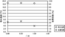
- FIG. 4 shows the relationship between the ratio l ′ / W of the dimension 1 ′ to the first dimension W, the suction temperature (the temperature of the air sucked by the blower 30), and the improvement index for the central unit 101.
- the dimension l ′ is a dimension from the central unit center plane P1 to the upper end of the central turning member 201.
- the improvement index is a value obtained by dividing the increase rate of the suction temperature of each blower 30 by providing the central turning member 201 by the increase rate of the pressure loss of each blower 30 by providing the central turning member 201.
- the curvature of the central deflecting member 201 is D / 2
- the dimension h is a quarter of the dimension H.
- the dimension w is 1 ⁇ 4 of the first dimension W.
- both the suction temperature and the improvement index are positive values regardless of the value of the ratio l ′ / W (the mounting position of the central deflecting member 201 with respect to the central unit 101). That is, the suction temperature of the blower 30 is increased by providing the central turning member 201. This is also presumed to be the same for the case where the lateral direction changing member 202 is provided in the lateral unit 102.
- each heat exchange device 20 When the blower 30 of each heat exchange unit 101, 102 is driven, a downward airflow is formed in each heat exchange device 20, and the low temperature medium is heated by the airflow coming into contact with the heat transfer tube 44. And although the airflow (low-temperature air cooled by contacting the heat transfer tube 44) after heat exchange in the heat exchanger 40 is directed to the ground, at least a part of the airflow is The direction is changed by the direction change members 201 and 202. Specifically, the center turning member 201 changes the direction of the airflow so that at least a part of the airflow includes a component that goes in a direction away from the central unit center plane P1 (a direction in which the side unit 102 is located). .
- the side direction changing member 202 changes the direction of the airflow so that at least a part of the airflow that has passed through each heat exchanger 40 of the side unit 102 includes a component that goes in a direction away from the central unit 101. For this reason, it is suppressed that the low temperature air which flowed out from the central unit 101 and the low temperature air which flowed out from the side unit 102 gather between the central unit 101 and the side unit 102 (retention of low temperature air). Re-suction of low-temperature air by each blower 30 of the side unit 102 is suppressed.
- the lateral direction changing member 202 is disposed at a position closer to the central unit 101 than the lateral unit center plane P2, the retention of the low-temperature air between the central unit 101 and the lateral unit 102 is further increased. Suppressed reliably. Specifically, the airflow redirected in the direction away from the central unit 101 by the lateral deflecting member 202 flows out from each heat exchanger 40 located on the side farther from the central unit 101 than the lateral unit center plane P2. Thus, the direction of the air flow toward the ground is changed so as to be away from the central unit 101. Therefore, the retention of low temperature air between the central unit 101 and the side unit 102 is more reliably suppressed.
- each of the deflecting members 201 and 202 has a shape that gradually curves downward and protrudes downward as it goes outward from the system center plane Ps in the one direction. For this reason, the raise of the pressure loss of each air blower 30 by providing a direction change member can be suppressed.
- the airflow that has passed through the heat exchanger 40 is provided with the blocking member 64 that blocks the flow of air toward the blower 30 side, re-suction of low-temperature air by the blower 30 is further suppressed.
- the heat exchange system of the present embodiment includes an even number (four in the present embodiment) of heat exchange units 111 and 121 arranged in one direction.
- the heat exchange units 111 and 121 are arranged so as to be arranged at equal intervals along one direction.
- each heat exchange unit arranged on one side (right side in FIG. 5) of the system center plane Ps in one direction among the plurality of heat exchange units 111 and 121 is referred to as “one side unit 111”, and a plurality of heat exchange units are arranged.
- each heat exchange unit arranged on the other side (left side in FIG. 5) of the system center plane Ps in one direction is referred to as “the other side unit 121”.
- a virtual plane that is orthogonal to the one direction and passes through the center of the one-side unit 111 in the one direction is referred to as a “one-side unit center plane P11”, and is parallel to the one-side unit center plane P11.
- a virtual plane that passes through the center of the other unit 121 in the one direction is referred to as “the other unit center plane P21”.
- This heat exchange system is formed symmetrically with the system center plane Ps as a symmetry plane. For this reason, only the one-side unit 111 will be described below. In FIG. 6, only the one-side unit 111 located on one side of the system center plane Ps in the present heat exchange system is shown.
- the structure of the one side unit 111 is basically the same as that of the side unit 102 of the first embodiment. That is, the one side unit 111 includes a plurality of heat exchange devices 20 and one side diverting member 211. A description of each heat exchange device 20 is omitted.
- the one-side diverting member 211 changes the direction of the airflow so that at least a part of the airflow includes a component that extends outward from the system center plane Ps in the one direction and horizontally.
- the shape of the one side turning member 211 is the same as that of the side turning member 202 of the first embodiment.
- the attachment position to the heat exchange apparatus 20 of the one side direction change member 211 is the same as that of the side direction change member 202 of 1st Embodiment. That is, in the one-side diverting member 211, the ratio l / W of the second dimension 1 to the first dimension W is 0.9 to 1.0 from the one-side unit center plane P11 toward the system center plane Ps. Placed in range.
- the first dimension W is a dimension between a surface located closest to the system center plane Ps among the outer surfaces of the heat exchange chambers 42 of the one-side unit 111 and the one-side unit center plane P11.
- the second dimension l is a dimension from the one-side unit center plane P11 to the upper end portion of the one-side diverting member 211.
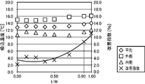
- FIG. 7 shows that in the case where the unit component 10 of the one-side unit 111 is constituted by two heat exchange devices 20, the curvature of the one-side diverting member 211 is D / 2, and the dimension h is the dimension H. The relationship is shown when the size is 1/4 and the dimension w is 1/4 of the first dimension W.
- the suction temperature the suction temperature of the blower 30 located on the side close to the system center plane Ps is “inside”, and the suction temperature of the blower 30 located on the side far from the system center plane Ps is “outside”.
- the average value of the inner side and the outer side is indicated as “average”.
- both the suction temperature and the improvement index are positive values, and the ratio l / W is 0.9 to 1.0. If it is within the range, the improvement index is 8.0% or more (high temperature rise effect is obtained). This is considered to hold true even in the case where an odd number of heat exchange units are arranged, that is, the mounting position of the side turning member 202 with respect to the side unit 102 of the first embodiment.
- the one-side diverting member 211 and the other-side diverting member are arranged in the range where the ratio l / W is 0.9 to 1.0, a high temperature raising effect can be obtained with respect to the suction temperature of the blower 30. .
- the heat exchange system may be configured by a single heat exchange unit.
- the heat exchange unit may have only a single unit component 10 or may have only a single heat exchange device 20.
- each of the deflecting members 201, 202, 211, and 221 is not limited to the example shown in the above embodiment.
- the shape of each diverting member can be appropriately changed within a range in which the direction of the airflow can be changed so that at least a part of the airflow that has passed through the heat exchanger 40 includes a component that goes horizontally.
- the deflecting member may be formed in a flat plate shape.
- the center turning member 201 is not limited to the example connected to the lower surface of the connecting portion 52.
- the center turning member 201 can be disposed at an arbitrary height position between the lower surface of the connecting portion 52 and the ground.
- the closer the arrangement of the central deflecting member 201 is to the lower surface of the connecting portion 52 the more easily the airflow that has passed through the heat exchanger 40 is redirected (in the direction away from the central unit 101) to include a horizontal component. Therefore, it is preferable that the center turning member 201 is connected to the lower surface of the connecting portion 52.
- the side diverting member 202, the one side diverting member 211, and the other side diverting member 221 are preferably connected to the lower surface of the heat exchange chamber 42, respectively.
- tread plate 62 may be omitted, and the overhanging portion 65 of the blocking member 64 may be connected to the upper end of the outer surface of the heat exchange chamber 42.
- the heat exchange unit of the above embodiment includes at least one heat exchange device and a diverting member, and the at least one heat exchange device has a blower that forms a downwardly flowing airflow, and the airflow and the air.
- a heat exchanger that heats the low-temperature medium by exchanging heat with a low-temperature low-temperature medium; and a support portion that supports the heat exchanger at a position spaced upward from the ground. The direction of the airflow is changed between the heat exchanger and the ground so that at least a part of the airflow includes a component that goes horizontally.
- the low-temperature air after heat exchange by the heat exchanger is changed.
- the blower is prevented from sucking again.
- at least a part of the low-temperature air is diverted to include a component that goes horizontally before colliding with the ground, and thus flows away from the heat exchange unit in the horizontal direction. Therefore, it is suppressed that the said low temperature air collides with the ground and the said low temperature air retains in the lower part or its periphery of a heat exchanger, and, thereby, the re-suction of the low temperature air by a fan is suppressed.
- the at least one heat exchange device includes a plurality of heat exchange devices arranged in one direction, and the diverting member has at least a part of the air flow along the one direction and horizontally. It is preferable to change the direction of the air flow so as to include components.
- the at least one heat exchange device has a plurality of unit components arranged along an orthogonal direction orthogonal to the one direction, and each unit component is a plurality of units arranged along the one direction.
- the heat exchange device is configured such that the number of the plurality of unit components is set to be greater than the number of the heat exchange devices included in each unit component, and the diverting member includes the plurality of unit components.
- a unit component located on one end side in the orthogonal direction has a shape extending along the orthogonal direction so as to reach a unit component element located on the other end side in the orthogonal direction. Is preferred.
- the heating amount of the low temperature medium can be further increased.
- the heat exchange unit further includes a blocking member that blocks airflow that has passed through the heat exchanger from moving toward the blower.
- the blocking member gradually extends upward as the protruding portion has a shape protruding outward from the outer surface of the heat exchanger and the outer edge of the protruding portion is separated from the heat exchanger. It is preferable to have an upright portion having a shape.
- the heat exchange system of the first embodiment is a heat exchange system having an odd number of heat exchange units, each heat exchange unit is the heat exchange unit, and the odd number of heat exchange units are: A central diverting member that is arranged along the one direction and that is a diverting member of a central unit that is arranged in the middle of the one direction among the odd number of heat exchange units is provided in the central unit.
- a side turning member which is a side member turning member disposed on the side of the central unit in one direction, is provided at one end in the orthogonal direction among a plurality of unit components included in the side unit. It has a shape extending along the orthogonal direction so as to reach a unit component located on the other end side in the orthogonal direction from the unit component positioned in the side unit.
- At least a part of the airflow is a plane orthogonal to the one direction and from a virtual system center plane passing through the center of the heat exchange system in the one direction.
- Serial redirecting of the air flow so as to include an outer and and horizontally directed component of one direction.
- the side turning member changes the direction of the airflow so that at least a part of the airflow includes a component that goes outward in one direction and horizontally from the system center plane.
- the cold air that has flowed out of the vessel goes away from the central unit. Therefore, the collection of the low-temperature air flowing out from the central unit and the low-temperature air flowing out from the side unit (retention of low-temperature air) is suppressed between the central unit and the side unit. Re-suction is suppressed.
- the central deflection member has a shape that gradually curves downward and convex downward as it goes outward from the central unit central plane in the one direction, and the lateral deflection. It is preferable that the member has a shape that gradually curves downward and protrudes downward as it goes outward from the system center plane in the one direction.
- the side diverting member is a plane orthogonal to the one direction and from the virtual side unit center plane passing through the center of the side unit in the one direction toward the central unit, With respect to the dimension from the side unit center surface to the end portion on the side close to the central unit among the heat exchangers of the side unit, from the side unit center surface to the upper end portion of the side turning member. It is preferable that the ratio of dimensions is in a range of 0.9 to 1.0.
- the center unit is closer to the center unit than the center surface of the side unit among the heat exchangers of the side unit. Most of the low-temperature air flowing out from the heat exchanger located on the side is directed away from the central unit.
- the airflow (the airflow redirected in the direction away from the central unit by the lateral deflecting member) flows out from each heat exchanger located on the side farther from the central unit than the side surface of the lateral unit and flows to the ground.
- the improvement index becomes 8% or more by disposing the side turning member in the range where the ratio is 0.9 to 1.0, a high temperature rise effect can be obtained with respect to the suction temperature of the blower.
- the improvement index is a value obtained by dividing the increase rate of the air suction temperature of each blower by providing each deflecting member by the increase rate of the pressure loss of each blower by providing each turning member.
- the heat exchange system of the second embodiment is a heat exchange system having an even number of heat exchange units, each heat exchange unit is the heat exchange unit, and the even number of heat exchange units are: A virtual system center that is arranged along the one direction and is a plane orthogonal to the one direction among the even number of heat exchange units and passes through the center of the heat exchange system in the one direction.
- the one-side diverting member that is the diverting member of the one-side unit disposed on one side of the surface is a unit component located on one end side in the orthogonal direction among the plurality of unit components included in the one-side unit. Along the orthogonal direction so as to reach a unit component located on the other end side in the orthogonal direction among the plurality of unit components included in the one-side unit.
- the even number of heat exchange units are configured to change the direction of the air flow so that at least a part of the air flow includes a component extending outwardly and horizontally in the one direction from the system center plane.
- the other direction turning member that is a direction changing member of the other side unit disposed on the other side of the system center plane in the one direction. Extending from the unit component located on one end side to the unit component located on the other end side in the orthogonal direction among the plurality of unit components included in the other unit.
- a direction of the airflow so that at least a part of the airflow includes a component that extends outwardly and horizontally in the one direction from the system center plane. Change.
- the one-side diverting member has a shape that gradually curves downward and convex downward toward the outside in the one direction from the system center plane, and the other-side diverting member. It is preferable that the member has a shape that gradually curves downward and protrudes downward as it goes outward from the system center plane in the one direction.
- the one-side diverting member is a plane orthogonal to the one direction and extends from the virtual one-side unit center plane passing through the center of the one-side unit in the one direction toward the system center plane.
- the upper end portion of the one-side diverting member from the one-side unit center surface to the dimension from the one-side unit center surface to the end portion close to the system center surface among the heat exchangers of the one-side unit.
- the other side diverting member is a plane perpendicular to the one direction, and the other side unit has a ratio of the dimensions up to 0.9 to 1.0.
- the end on the side closer to the system central plane among the heat exchangers of the other side unit from the other side unit central plane is preferably disposed in the range of 0.9 to 1.0.
Landscapes
- Engineering & Computer Science (AREA)
- Mechanical Engineering (AREA)
- General Engineering & Computer Science (AREA)
- Physics & Mathematics (AREA)
- Thermal Sciences (AREA)
- Heat-Exchange Devices With Radiators And Conduit Assemblies (AREA)
- Details Of Heat-Exchange And Heat-Transfer (AREA)
- Separation By Low-Temperature Treatments (AREA)
- Other Air-Conditioning Systems (AREA)
- Air Filters, Heat-Exchange Apparatuses, And Housings Of Air-Conditioning Units (AREA)
Abstract
熱交換ユニットであって、少なくとも1つの熱交換装置(20)と、変向部材(201)と、を備える。熱交換装置(20)は、下向きに流れる気流を形成する送風機(30)と、前記気流と空気よりも低温の低温媒体とを熱交換させることによって低温媒体を加熱する熱交換器(40)と、熱交換器(40)を地面から上方に離間した位置に支持する支持部(50)と、を備える。変向部材(201)は、熱交換器(40)と地面との間において、前記気流の少なくとも一部が水平に向かう成分を含むように当該気流の向きを変える。
Description
本発明は、熱交換ユニット及び熱交換システムに関するものである。
従来、液化天然ガス(LNG)等の低温液化ガスを空気(大気)で加熱することによって気化させる空温式の気化装置が知られている。例えば、特許文献1には、下降気流を生じさせる外気吸引ファンと、下降気流と低温液化ガスとを熱交換させることにより低温液化ガスを気化させる蒸発管と、蒸発管を地面から上方に離間した位置に支持する架台と、を備える低温液化ガス気化装置(熱交換装置)が開示されている。
特許文献1に記載されるような低温液化ガス気化装置では、蒸発管に接触することにより冷却された低温空気(前記下降気流のうち蒸発管の下流側に位置する空気)が、再度外気吸引ファンにより吸い込まれる場合がある。具体的に、外気吸込ファンにより形成される気流は下向きであるので、前記低温空気は、地面に衝突した後に蒸発管の下部ないしその周辺に滞留しやすく、このため、その低温空気が外気吸引ファンにより再び吸い込まれる場合がある。この場合、蒸発管に供給される空気(下降気流)の温度が蒸発管と熱交換した後の気流の温度とほとんど同じになるので、蒸発管において有効な熱交換(低温液化ガスの加熱)が行われなくなる。
本発明の目的は、低温空気の再吸込を抑制可能な熱交換ユニット及び熱交換システムを提供することである。
本発明の一局面に従う熱交換ユニットは、少なくとも1つの熱交換装置と、変向部材と、を備え、前記少なくとも1つの熱交換装置は、下向きに流れる気流を形成する送風機と、前記気流と空気よりも低温の低温媒体とを熱交換させることによって前記低温媒体を加熱する熱交換器と、前記熱交換器を地面から上方に離間した位置に支持する支持部と、を備え、前記変向部材は、前記熱交換器と地面との間において、前記気流の少なくとも一部が水平に向かう成分を含むように当該気流の向きを変える。
また、本発明の一局面に従う熱交換システムは、奇数個の熱交換ユニットを有する熱交換システムであって、各熱交換ユニットは、前記熱交換ユニットであり、前記奇数個の熱交換ユニットは、前記一方向に沿って並ぶように配置されており、前記奇数個の熱交換ユニットのうち前記一方向の中央に配置された中央ユニットの変向部材である中央変向部材は、前記中央ユニットに含まれる複数のユニット構成要素のうち前記直交方向の一端側に位置するユニット構成要素から前記中央ユニットに含まれる前記複数のユニット構成要素のうち前記直交方向の他端側に位置するユニット構成要素に至るように、前記一方向と直交する平面であって前記一方向について前記中央ユニットの中央を通る仮想的な中央ユニット中心面に沿って延びる形状を有し、かつ、前記気流の少なくとも一部が、前記中央ユニット中心面から前記一方向の外側でかつ水平に向かう成分を含むように当該気流の向きを変え、前記複数の熱交換ユニットのうち前記一方向について前記中央ユニットの側方に配置された側方ユニットの変向部材である側方変向部材は、前記側方ユニットに含まれる複数のユニット構成要素のうち前記直交方向の一端側に位置するユニット構成要素から前記側方ユニットに含まれる前記複数のユニット構成要素のうち前記直交方向の他端側に位置するユニット構成要素に至るように、前記直交方向に沿って延びる形状を有し、かつ、前記気流の少なくとも一部が、前記一方向と直交する平面であって前記一方向について当該熱交換システムの中央を通る仮想的なシステム中心面から前記一方向の外側でかつ水平に向かう成分を含むように当該気流の向きを変える。
また、本発明の他の局面に従う熱交換システムは、偶数個の熱交換ユニットを有する熱交換システムであって、各熱交換ユニットは、前記熱交換ユニットであり、前記偶数個の熱交換ユニットは、前記一方向に沿って並ぶように配置されており、前記偶数個の熱交換ユニットのうち前記一方向と直交する平面であって前記一方向について当該熱交換システムの中央を通る仮想的なシステム中心面の一方側に配置された一方側ユニットの変向部材である一方側変向部材は、前記一方側ユニットに含まれる複数のユニット構成要素のうち前記直交方向の一端側に位置するユニット構成要素から前記一方側ユニットに含まれる前記複数のユニット構成要素のうち前記直交方向の他端側に位置するユニット構成要素に至るように、前記直交方向に沿って延びる形状を有し、かつ、前記気流の少なくとも一部が、前記システム中心面から前記一方向の外側でかつ水平に向かう成分を含むように当該気流の向きを変え、前記偶数個の熱交換ユニットのうち前記一方向について前記システム中心面の他方側に配置された他方側ユニットの変向部材である他方側変向部材は、前記他方側ユニットに含まれる複数のユニット構成要素のうち前記直交方向の一端側に位置するユニット構成要素から前記他方側ユニットに含まれる前記複数のユニット構成要素のうち前記直交方向の他端側に位置するユニット構成要素に至るように、前記直交方向に沿って延びる形状を有し、かつ、前記気流の少なくとも一部が、前記システム中心面から前記一方向の外側でかつ水平に向かう成分を含むように当該気流の向きを変える。
本発明の好ましい実施形態について、以下、図面を参照しながら説明する。
(第1実施形態)
本発明の第1実施形態の熱交換システムについて、図1~図4を参照しながら説明する。本熱交換システムは、空気(大気)よりも低温の低温媒体(低温液化ガス、中間媒体等)と空気とを熱交換させることにより低温媒体を加熱するシステムである。なお、本熱交換システムは、空気で直接低温液化ガスを加熱するために用いられてもよいし、いわゆる中間媒体式の熱交換システム(プロパン等の中間媒体により低温液化ガスを加熱する装置)において中間媒体を加熱するために用いられてもよい。
本発明の第1実施形態の熱交換システムについて、図1~図4を参照しながら説明する。本熱交換システムは、空気(大気)よりも低温の低温媒体(低温液化ガス、中間媒体等)と空気とを熱交換させることにより低温媒体を加熱するシステムである。なお、本熱交換システムは、空気で直接低温液化ガスを加熱するために用いられてもよいし、いわゆる中間媒体式の熱交換システム(プロパン等の中間媒体により低温液化ガスを加熱する装置)において中間媒体を加熱するために用いられてもよい。
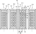
図1~図3に示されるように、本熱交換システムは、一方向(図1の左右方向)に沿って並ぶ奇数個(本実施形態では3個)の熱交換ユニット101,102を備えている。
以下、奇数個の熱交換ユニット101,102のうち前記一方向の中央に位置する熱交換ユニットを「中央ユニット101」といい、奇数個の熱交換ユニット101,102のうち前記一方向について中央ユニット101の側方に配置された熱交換ユニットを「側方ユニット102」という。また、前記一方向と直交する平面であって前記一方向について中央ユニット101の中央を通る仮想的な平面を「中央ユニット中心面P1」といい、この中央ユニット中心面P1と平行な平面であって前記一方向について側方ユニット102の中央を通る仮想的な平面を「側方ユニット中心面P2」といい、前記一方向と直交する平面であって前記一方向について当該熱交換システムの中央を通る仮想的な平面を「システム中心面Ps」という。本実施形態では、中央ユニット中心面P1がシステム中心面Psと一致するように、換言すれば、各熱交換ユニット101,102が一方向に沿って等間隔で並ぶようにこれら熱交換ユニット101,102が配置されている。ただし、各熱交換ユニット101,102は、互いに隣接する熱交換ユニットの寸法がそれぞれ異なるように、つまり、中央ユニット中心面P1がシステム中心面Psから一方向に離間するように配置されてもよい。また、本実施形態では、熱交換システムは、システム中心面Psを対称面として面対称に形成されている。
中央ユニット101は、複数の熱交換装置20と、中央変向部材201と、を有している。
各熱交換装置20は、空気と低温媒体とを熱交換させることにより低温媒体を加熱する装置である。複数の熱交換装置20は、複数の行と複数の列とにより形成される行列状に並ぶように配置されている。各行は、前記一方向と平行であり、各列は、前記一方向と直交する直交方向(図1の上下方向)と平行である。以下、一方向に沿って並ぶ複数の熱交換装置20(各行に含まれる複数の熱交換装置20)をまとめて「ユニット構成要素10」という。本実施形態では、ユニット構成要素10は、2つの熱交換装置20からなり、中央ユニット101は、6つのユニット構成要素10を有している。ただし、各ユニット構成要素10に含まれる熱交換装置20の数及び中央ユニット101に含まれるユニット構成要素10の数は、これに限られない。中央ユニット101に含まれるユニット構成要素10の数は、各ユニット構成要素10を構成する熱交換装置20の数よりも大きく設定されることが好ましい。各熱交換装置20は、中央ユニット中心面P1を対称面として面対称となるように配置されている。各熱交換装置20は、送風機30と、熱交換器40と、支持部50と、を有している。
送風機30は、下向きに流れる気流(下降気流)を形成する。具体的に、送風機30は、円筒状の送風機室32と、送風機室32内に配置されたファン34と、ファン34を駆動するモータ(図示略)と、を有する。ファン34は、モータが駆動したときに鉛直下向きに流れる下降気流を形成する姿勢で送風機室32内に配置されている。
熱交換器40は、送風機30により形成された下降気流(空気)と低温媒体とを熱交換させることによって低温媒体の少なくとも一部を蒸発させる。具体的に、熱交換器40は、熱交換室42と、熱交換室42内に配置された伝熱管44と、を有する。
熱交換室42は、四角筒状に形成されている。熱交換室42の上端は、中空状の連結部36を介して送風機室32の下端に接続されている。このため、送風機30により形成された気流は、熱交換室42内を通って当該熱交換室42の下方に向かう。
伝熱管44内には、低温媒体(低温液化ガスや中間媒体)が流れる。熱交換室42内において伝熱管44に前記気流が接触することにより、つまり、前記気流と低温媒体とが熱交換することにより、伝熱管44内を流れる低温媒体の少なくとも一部が蒸発する。本実施形態では、各ユニット構成要素10の一方側(図3の右側)の伝熱管44と他方側(図3の左側)の伝熱管44とは、互いに連通するように形成されている。また、前記一方側の伝熱管44は、熱交換室42内で折り返されている。
支持部50は、熱交換器40を地面から上方に離間した位置に支持する。具体的に、支持部50は、熱交換室42の中心軸が鉛直方向と平行となる姿勢で当該熱交換室42を支持している。なお、送風機室32の中心軸も、鉛直方向と平行な姿勢となる。
本実施形態では、熱交換室42の外側面に、踏み板62と、遮断部材64と、が接続されている。
踏み板62は、網状に形成されており、熱交換室42の外側面の上端に接続されている。この踏み板62は、当該踏み板62上を人が歩くことができる程度の強度に設定される。
遮断部材64は、熱交換器40を通過した気流が熱交換室42の外側面及び連結部36の外側面に沿って送風機30側(上方)に向かうのを遮断する。遮断部材64は、張出部65と、起立部66と、を有する。張出部65は、熱交換室42の外側面のうち踏み板62よりも下方の部位に接続されている。張出部65は、熱交換室42の外側面から水平方向でかつ当該外側面から離間する向きに張り出す形状を有する。張出部65は、互いに隣接する熱交換室42の外側面間を塞ぐ形状を有する。起立部66は、張出部65の外縁に接続されている。具体的に、起立部66は、張出部65の外縁から熱交換室42から離間するにしたがって次第に上方に向かうように傾斜する形状を有する。張出部65及び起立部66は、平板状に形成されている。
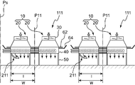
中央変向部材201は、熱交換器40と地面との間において、前記気流(熱交換器40で熱交換した後の低温空気)の少なくとも一部が水平に向かう成分を含むように当該気流の向きを変える。より具体的には、中央変向部材201は、前記気流の少なくとも一部が地面に衝突(到達)する前に、前記一方向に沿いかつ水平に向かう成分を含むように当該気流の向きを変える。中央変向部材201は、中央ユニット101の熱交換室42の下端部同士を連結する連結部52(図3を参照)の下面に接続されている。中央変向部材201の形状は、中央ユニット中心面P1(本実施形態ではシステム中心面Ps)を対称面として面対称に形成されている。中央変向部材201は、前記気流の少なくとも一部が、中央ユニット中心面P1から前記一方向の外側(側方ユニット102側)でかつ水平に向かう成分を含むように当該気流の向きを変える。中央変向部材201は、中央ユニット101に含まれる複数のユニット構成要素10のうち前記直交方向の一端側に位置するユニット構成要素10から中央ユニット101に含まれる複数のユニット構成要素10のうち前記直交方向の他端側に位置するユニット構成要素10に至るように、中央ユニット中心面P1に沿って延びる形状を有する。
本実施形態では、中央変向部材201は、中央ユニット中心面P1から前記一方向の外側に向かうにしたがって次第に下方に向かうとともに下向きに凸となるように湾曲する形状を有する。中央変向部材201の曲率は、熱交換室42の一方向の寸法D(図3を参照)の例えば2分の1に設定される。中央変向部材201の一方向の寸法w(図3を参照)は、熱交換室42の外側面のうち中央ユニット中心面P1から最も遠くに位置する面と中央ユニット中心面P1との間の第1寸法W(図2及び図3を参照)の例えば4分の1に設定される。中央変向部材201の上下方向の寸法h(図3を参照)は、熱交換室42の下面と地面との間の寸法H(図3を参照)の例えば4分の1に設定される。
本実施形態では、中央ユニット101の一方側に配置された側方ユニット102と中央ユニット101の他方側に配置された側方ユニット102とは、システム中心面Psを対称面として面対称に構成されているので、以下、一方側の側方ユニット102についてのみ説明する。側方ユニット102は、複数の熱交換装置20と、側方変向部材202と、を有している。
各熱交換装置20の配置は、中央ユニット101のそれと同様である。すなわち、側方ユニット102は、直交方向に沿って並ぶ6つのユニット構成要素10を有しており、各ユニット構成要素10は、一方向に沿って並ぶ2つの複数の熱交換装置20からなる。また、各熱交換装置20は、側方ユニット中心面P2を対称面として面対称となるように配置されている。各熱交換装置20の構造は、中央ユニット101のそれと同じであるので、その説明を省略する。また、側方ユニット102は、中央ユニット101と同様に、踏み板62及び遮断部材64を有している。
側方変向部材202は、側方ユニット102の各熱交換室42のうち側方ユニット中心面P2よりも中央ユニット101に近い側に位置する熱交換室42の下部に接続されている。具体的に、側方変向部材202は、側方ユニット中心面P2から中央ユニット101に向かって、第1寸法W(側方ユニット102の各熱交換室42の外側面のうち最も中央ユニット101の近くに位置する面と側方ユニット中心面P2との間の寸法)に対する第2寸法lの割合l/Wが、0.9~1.0となる範囲に配置される。第2寸法lは、側方ユニット中心面P2から側方変向部材202の上端部までの寸法である。側方変向部材202は、前記気流の少なくとも一部が、システム中心面Ps(中央ユニット101)から前記一方向の外側でかつ水平に向かう成分を含むように当該気流の向きを変える。側方変向部材202は、側方ユニット102に含まれる複数のユニット構成要素10のうち前記直交方向の一端側に位置するユニット構成要素10から側方ユニット102に含まれる複数のユニット構成要素10のうち前記直交方向の他端側に位置するユニット構成要素10に至るように、前記直交方向に沿って延びる形状を有する。側方変向部材202は、中央ユニット101から離間する(側方ユニット中心面P2に向かう)にしたがって次第に下方に向かうとともに下向きに凸となるように湾曲する形状を有する。側方変向部材202の曲率、一方向の寸法w、及び、上下方向の寸法hは、それぞれ中央変向部材201のそれと同じに設定されている。
次に、図4を参照しながら、各変向部材を設けることによる効果について説明する。図4は、中央ユニット101について、第1寸法Wに対する寸法l′の割合l′/Wと、吸込温度(送風機30が吸い込む空気の温度)及び改善指数と、の関係を示している。前記寸法l′は、中央ユニット中心面P1から中央変向部材201の上端までの寸法である。改善指数は、中央変向部材201を設けることによる各送風機30の吸込温度の上昇割合を、中央変向部材201を設けることによる各送風機30の圧力損失の上昇割合で除した値である。ここで、図4は、ユニット構成要素10が2つの熱交換装置20からなる場合において、中央変向部材201の曲率がD/2であり、前記寸法hが前記寸法Hの4分の1であり、前記寸法wが前記第1寸法Wの4分の1である場合の関係を示している。
図4に示されるように、前記割合l′/Wの値(中央変向部材201の中央ユニット101に対する取付位置)にかかわらず、吸込温度及び改善指数がともに正の値となっている。すなわち、中央変向部材201を設けることにより送風機30の吸込温度が上昇する。このことは、側方ユニット102に側方変向部材202を設けた場合についても同様と推察される。
以上に説明した熱交換システムの動作について説明する。
各熱交換ユニット101,102の送風機30が駆動されると、それぞれの熱交換装置20において下向きの気流が形成され、この気流が伝熱管44と接触することにより低温媒体が加熱される。そして、熱交換器40において熱交換した後の気流(伝熱管44に接触することより冷却された低温空気)は、地面に向かうものの、その気流の少なくとも一部は、地面に衝突する前に各変向部材201,202により変向される。具体的に、中央変向部材201は、前記気流の少なくとも一部が中央ユニット中心面P1から離間する方向(側方ユニット102が位置する方向)に向かう成分を含むように当該気流の向きを変える。このため、前記気流(低温空気)の少なくとも一部は、地面に衝突する前に、中央ユニット101から水平方向に遠ざかるように流れる。よって、前記低温空気が地面へ衝突することにより当該低温空気が熱交換器40の下部ないしその周辺に滞留することが抑制され、これにより中央ユニット101の各送風機30による低温空気の再吸込が抑制される。
また、側方変向部材202は、側方ユニット102の各熱交換器40を通過した気流の少なくとも一部が中央ユニット101から離間する方向に向かう成分を含むように当該気流の向きを変える。このため、中央ユニット101と側方ユニット102との間に、中央ユニット101から流出した低温空気と側方ユニット102から流出した低温空気とが集まること(低温空気の滞留)が抑制され、これにより側方ユニット102の各送風機30による低温空気の再吸込が抑制される。
さらに、側方変向部材202は、側方ユニット中心面P2よりも中央ユニット101に近い位置に配置されているので、中央ユニット101と側方ユニット102との間への低温空気の滞留がより確実に抑制される。具体的に、側方変向部材202により中央ユニット101から離間する方向に変向された気流は、側方ユニット中心面P2よりも中央ユニット101から遠い側に位置する各熱交換器40から流出して地面に向かう気流の向きを、中央ユニット101から離間する方向に変えるように作用する。よって、中央ユニット101と側方ユニット102との間への低温空気の滞留がより確実に抑制される。
また、各変向部材201,202は、システム中心面Psから前記一方向の外側に向かうにしたがって次第に下方に向かうとともに下向きに凸となるように湾曲する形状を有している。このため、変向部材を設けることによる各送風機30の圧力損失の上昇を抑制することができる。
また、熱交換器40を通過した気流が送風機30側に向かうのを遮断する遮断部材64を有するので、送風機30による低温空気の再吸込が一層抑制される。
(第2実施形態)
次に、図5~図7を参照しながら、本発明の第2実施形態の熱交換システムについて説明する。なお、第2実施形態では、第1実施形態と異なる部分についてのみ説明を行い、第1実施形態と同じ構造、作用及び効果の説明は省略する。
次に、図5~図7を参照しながら、本発明の第2実施形態の熱交換システムについて説明する。なお、第2実施形態では、第1実施形態と異なる部分についてのみ説明を行い、第1実施形態と同じ構造、作用及び効果の説明は省略する。
本実施形態の熱交換システムは、一方向に沿って並ぶ偶数個(本実施形態では4個)の熱交換ユニット111,121を備えている。本実施形態では、各熱交換ユニット111,121は、一方向に沿って等間隔で並ぶように配置されている。
以下、複数の熱交換ユニット111,121のうち一方向についてシステム中心面Psの一方側(図5の右側)に配置された各熱交換ユニットを「一方側ユニット111」といい、複数の熱交換ユニット111,121のうち一方向についてシステム中心面Psの他方側(図5の左側)に配置された各熱交換ユニットを「他方側ユニット121」という。また、前記一方向と直交する平面であって前記一方向について一方側ユニット111の中央を通る仮想的な平面を「一方側ユニット中心面P11」といい、この一方側ユニット中心面P11と平行な平面であって前記一方向について他方側ユニット121の中央を通る仮想的な平面を「他方側ユニット中心面P21」という。本熱交換システムは、システム中心面Psを対称面として面対称に形成されている。このため、以下では、一方側ユニット111についてのみ説明する。なお、図6では、本熱交換システムのうちシステム中心面Psの一方側に位置する一方側ユニット111のみが示されている。
一方側ユニット111の構造は、第1実施形態の側方ユニット102のそれと基本的に同様である。すなわち、一方側ユニット111は、複数の熱交換装置20と、一方側変向部材211と、を有している。各熱交換装置20についての説明は、省略する。
一方側変向部材211は、前記気流の少なくとも一部が、システム中心面Psから前記一方向の外側でかつ水平に向かう成分を含むように当該気流の向きを変える。一方側変向部材211の形状は、第1実施形態の側方変向部材202のそれと同じである。また、一方側変向部材211の熱交換装置20への取付位置は、第1実施形態の側方変向部材202のそれと同じである。すなわち、一方側変向部材211は、一方側ユニット中心面P11からシステム中心面Psに向かって、第1寸法Wに対する第2寸法lの割合l/Wが、0.9~1.0となる範囲に配置される。なお、第1寸法Wは、一方側ユニット111の各熱交換室42の外側面のうち最もシステム中心面Psの近くに位置する面と一方側ユニット中心面P11との間の寸法である。第2寸法lは、一方側ユニット中心面P11から一方側変向部材211の上端部までの寸法である。
次に、図7を参照しながら、前記割合l/Wと、吸込温度及び改善指数と、の関係について説明する。図7は、一方側ユニット111のユニット構成要素10が2つの熱交換装置20により構成される場合において、一方側変向部材211の曲率がD/2であり、前記寸法hが前記寸法Hの4分の1であり、前記寸法wが前記第1寸法Wの4分の1である場合の関係を示している。なお、図7では、吸込温度について、システム中心面Psに近い側に位置する送風機30の吸込温度が「内側」、システム中心面Psから遠い側に位置する送風機30の吸込温度が「外側」、そして、内側と外側の平均値が「平均」として示されている。
図7に示されるように、前記割合l/Wの値にかかわらず、吸込温度及び改善指数がともに正の値となっており、しかも、前記割合l/Wが0.9~1.0の範囲内であれば、改善指数が8.0%以上となっている(高い昇温効果が得られている)。このことは、熱交換ユニットが奇数個並んでいる場合においても、すなわち、第1実施形態の側方ユニット102に対する側方変向部材202の取付位置についても同様に成立すると考えられる。
以上に説明した本実施形態においても、各送風機30による低温空気の再吸込が有効に抑制される。
また、前記割合l/Wが0.9~1.0となる範囲に一方側変向部材211及び他方側変向部材が配置されるので、送風機30の吸込温度について高い昇温効果が得られる。
なお、今回開示された実施形態は、すべての点で例示であって制限的なものではないと考えられるべきである。本発明の範囲は、上記した実施形態の説明ではなく特許請求の範囲によって示され、さらに特許請求の範囲と均等の意味および範囲内でのすべての変更が含まれる。
例えば、上記実施形態では、熱交換システムが複数の熱交換ユニットを有している例が示されたが、熱交換システムは、単一の熱交換ユニットにより構成されてもよい。また、熱交換ユニットは、単一のユニット構成要素10のみを有していてもよく、あるいは、単一の熱交換装置20のみを有していてもよい。
また、各変向部材201,202,211,221の形状は、上記実施形態で示された例に限られない。各変向部材の形状は、熱交換器40を通過した気流の少なくとも一部が水平に向かう成分を含むように当該気流の向きを変えることができる範囲で適宜変更し得る。例えば、変向部材は、平板状に形成されてもよい。
また、中央変向部材201は、連結部52の下面に接続される例に限られない。中央変向部材201は、連結部52の下面と地面との間の任意の高さ位置に配置されることが可能である。ただし、中央変向部材201の配置が連結部52の下面に近づくほど、熱交換器40を通過した気流が水平に向かう成分を含むように(中央ユニット101から離間する方向に)変向されやすいため、中央変向部材201は、連結部52の下面に接続されることが好ましい。同様に、側方変向部材202、一方側変向部材211及び他方側変向部材221は、それぞれ熱交換室42の下面に接続されることが好ましい。
また、踏み板62が省略され、遮断部材64の張出部65が熱交換室42の外側面の上端に接続されてもよい。
ここで、上記実施形態について概説する。
上記実施形態の熱交換ユニットは、少なくとも1つの熱交換装置と、変向部材と、を備え、前記少なくとも1つの熱交換装置は、下向きに流れる気流を形成する送風機と、前記気流と空気よりも低温の低温媒体とを熱交換させることによって前記低温媒体を加熱する熱交換器と、前記熱交換器を地面から上方に離間した位置に支持する支持部と、を備え、前記変向部材は、前記熱交換器と地面との間において、前記気流の少なくとも一部が水平に向かう成分を含むように当該気流の向きを変える。
本熱交換ユニットでは、熱交換器を通過した後の気流の少なくとも一部が変向部材により水平に向かう成分を含むように変向されるので、熱交換器で熱交換した後の低温空気を送風機が再度吸い込むことが抑制される。具体的に、前記低温空気の少なくとも一部は、地面に衝突する前に水平に向かう成分を含むように変向されることにより、本熱交換ユニットから水平方向に遠ざかるように流れる。よって、前記低温空気が地面へ衝突することにより当該低温空気が熱交換器の下部ないしその周辺に滞留することが抑制され、これにより送風機による低温空気の再吸込が抑制される。
この場合において、前記少なくとも1つの熱交換装置は、一方向に沿って並ぶ複数の熱交換装置を含み、前記変向部材は、前記気流の少なくとも一部が、前記一方向に沿いかつ水平に向かう成分を含むように当該気流の向きを変えることが好ましい。
このようにすれば、低温媒体の加熱量の増大と、送風機による低温空気の再吸込の抑制と、を両立することができる。具体的に、各熱交換器において低温媒体が加熱されるので、低温媒体の加熱量が増大し、しかも、各熱交換器で熱交換した後の気流の少なくとも一部は、変向部材により前記一方向に沿いかつ水平方向に、すなわち、当該熱交換ユニットから遠ざかるように流れるので、各送風機による低温空気の再吸込が抑制される。
さらにこの場合において、前記少なくとも1つの熱交換装置は、前記一方向と直交する直交方向に沿って並ぶ複数のユニット構成要素を有し、各ユニット構成要素は、前記一方向に沿って並ぶ複数の熱交換装置からなり、前記複数のユニット構成要素の数は、各ユニット構成要素に含まれる前記熱交換装置の数よりも多く設定されており、前記変向部材は、前記複数のユニット構成要素のうち前記直交方向の一端側に位置するユニット構成要素から前記複数のユニット構成要素のうち前記直交方向の他端側に位置するユニット構成要素に至るように前記直交方向に沿って延びる形状を有することが好ましい。
このようにすれば、直交方向に沿って並ぶ複数のユニット構成要素の各熱交換器から流出した低温空気が当該熱交換ユニットから遠ざかるように流れるので、各送風機による低温空気の再吸込を抑制しながら、低温媒体の加熱量をさらに増やすことができる。
また、前記熱交換ユニットにおいて、前記熱交換器を通過した気流が前記送風機側に向かうのを遮断する遮断部材をさらに備えることが好ましい。
このようにすれば、送風機による低温空気の再吸込が一層抑制される。
具体的に、前記遮断部材は、前記熱交換器の外側面から外向きに張り出す形状を有する張出部と、前記張出部の外縁から前記熱交換器から離間するにしたがって次第に上方に向かう形状を有する起立部と、を有することが好ましい。
このようにすれば、送風機による低温空気の再吸込がより確実に抑制される。
また、上記第1実施形態の熱交換システムは、奇数個の熱交換ユニットを有する熱交換システムであって、各熱交換ユニットは、前記熱交換ユニットであり、前記奇数個の熱交換ユニットは、前記一方向に沿って並ぶように配置されており、前記奇数個の熱交換ユニットのうち前記一方向の中央に配置された中央ユニットの変向部材である中央変向部材は、前記中央ユニットに含まれる複数のユニット構成要素のうち前記直交方向の一端側に位置するユニット構成要素から前記中央ユニットに含まれる前記複数のユニット構成要素のうち前記直交方向の他端側に位置するユニット構成要素に至るように、前記一方向と直交する平面であって前記一方向について前記中央ユニットの中央を通る仮想的な中央ユニット中心面に沿って延びる形状を有し、かつ、前記気流の少なくとも一部が、前記中央ユニット中心面から前記一方向の外側でかつ水平に向かう成分を含むように当該気流の向きを変え、前記複数の熱交換ユニットのうち前記一方向について前記中央ユニットの側方に配置された側方ユニットの変向部材である側方変向部材は、前記側方ユニットに含まれる複数のユニット構成要素のうち前記直交方向の一端側に位置するユニット構成要素から前記側方ユニットに含まれる前記複数のユニット構成要素のうち前記直交方向の他端側に位置するユニット構成要素に至るように、前記直交方向に沿って延びる形状を有し、かつ、前記気流の少なくとも一部が、前記一方向と直交する平面であって前記一方向について当該熱交換システムの中央を通る仮想的なシステム中心面から前記一方向の外側でかつ水平に向かう成分を含むように当該気流の向きを変える。
本熱交換システムによれば、各送風機による低温空気の再吸込を抑制しながら、低温媒体の加熱量をさらに増やすことができる。具体的に、側方変向部材は、気流の少なくとも一部がシステム中心面から一方向の外側でかつ水平に向かう成分を含むように当該気流の向きを変えるので、側方ユニットの各熱交換器から流出した低温空気は、中央ユニットから離れる方向に向かう。よって、中央ユニットと側方ユニットとの間に、中央ユニットから流出した低温空気と側方ユニットから流出した低温空気とが集まること(低温空気の滞留)が抑制され、これにより各送風機による低温空気の再吸込が抑制される。
この場合において、前記中央変向部材は、前記中央ユニット中心面から前記一方向の外側に向かうにしたがって次第に下方に向かうとともに下向きに凸となるように湾曲する形状を有し、前記側方変向部材は、前記システム中心面から前記一方向の外側に向かうにしたがって次第に下方に向かうとともに下向きに凸となるように湾曲する形状を有することが好ましい。
このようにすれば、各変向部材を設けることによる各送風機の圧力損失の上昇を抑制することができ、さらに、中央ユニットから流出した低温空気は側方ユニットに向かい、かつ、側方ユニットから流出した低温空気は中央ユニットから離間する方向に向かうので、各送風機による低温空気の再吸込が有効に抑制される。
具体的に、前記側方変向部材は、前記一方向と直交する平面であって前記一方向について前記側方ユニットの中央を通る仮想的な側方ユニット中心面から前記中央ユニットに向かって、前記側方ユニット中心面から当該側方ユニットの各熱交換器のうち前記中央ユニットに近い側の端部までの寸法に対する、前記側方ユニット中心面から当該側方変向部材の上端部までの寸法の割合が、0.9~1.0となる範囲に配置されていることが好ましい。
このようにすれば、側方ユニットの各送風機のうち側方ユニット中心面よりも中央ユニットに近い側に位置する送風機による低温空気の再吸込がより有効に抑制される。具体的に、前記割合が0.9~1.0となる範囲に側方変向部材を配置することにより、側方ユニットの各熱交換器のうち側方ユニット中心面よりも中央ユニットに近い側に位置する熱交換器から流出した低温空気の大部分が中央ユニットから離れる方向に向かう。そして、その気流(側方変向部材により中央ユニットから離間する方向に変向された気流)は、側方ユニット中心面よりも中央ユニットから遠い側に位置する各熱交換器から流出して地面に向かう気流の向きを、中央ユニットから離間する方向に変えるように作用する。よって、中央ユニットと側方ユニットとの間への低温空気の滞留が一層抑制される。このため、各送風機による低温空気の再吸込が有効に抑制される。
さらに、前記割合が0.9~1.0となる範囲に側方変向部材を配置することにより、改善指数が8%以上となるので、送風機の吸込温度について高い昇温効果が得られる。改善指数とは、各変向部材を設けることによる各送風機の空気の吸込温度の上昇割合を、各変向部材を設けることによる各送風機の圧力損失の上昇割合で除した値である。
また、上記第2実施形態の熱交換システムは、偶数個の熱交換ユニットを有する熱交換システムであって、各熱交換ユニットは、前記熱交換ユニットであり、前記偶数個の熱交換ユニットは、前記一方向に沿って並ぶように配置されており、前記偶数個の熱交換ユニットのうち前記一方向と直交する平面であって前記一方向について当該熱交換システムの中央を通る仮想的なシステム中心面の一方側に配置された一方側ユニットの変向部材である一方側変向部材は、前記一方側ユニットに含まれる複数のユニット構成要素のうち前記直交方向の一端側に位置するユニット構成要素から前記一方側ユニットに含まれる前記複数のユニット構成要素のうち前記直交方向の他端側に位置するユニット構成要素に至るように、前記直交方向に沿って延びる形状を有し、かつ、前記気流の少なくとも一部が、前記システム中心面から前記一方向の外側でかつ水平に向かう成分を含むように当該気流の向きを変え、前記偶数個の熱交換ユニットのうち前記一方向について前記システム中心面の他方側に配置された他方側ユニットの変向部材である他方側変向部材は、前記他方側ユニットに含まれる複数のユニット構成要素のうち前記直交方向の一端側に位置するユニット構成要素から前記他方側ユニットに含まれる前記複数のユニット構成要素のうち前記直交方向の他端側に位置するユニット構成要素に至るように、前記直交方向に沿って延びる形状を有し、かつ、前記気流の少なくとも一部が、前記システム中心面から前記一方向の外側でかつ水平に向かう成分を含むように当該気流の向きを変える。
本熱交換システムにおいても、各送風機による低温空気の再吸込を抑制しながら、低温媒体の加熱量をさらに増やすことができる。
この場合において、前記一方側変向部材は、前記システム中心面から前記一方向の外側に向かうにしたがって次第に下方に向かうとともに下向きに凸となるように湾曲する形状を有し、前記他方側変向部材は、前記システム中心面から前記一方向の外側に向かうにしたがって次第に下方に向かうとともに下向きに凸となるように湾曲する形状を有することが好ましい。
このようにすれば、各変向部材を設けることによる各送風機の圧力損失の上昇を抑制することができ、さらに、各送風機による低温空気の再吸込が有効に抑制される。
具体的に、前記一方側変向部材は、前記一方向と直交する平面であって前記一方向について前記一方側ユニットの中央を通る仮想的な一方側ユニット中心面から前記システム中心面に向かって、前記一方側ユニット中心面から当該一方側ユニットの各熱交換器のうち前記システム中心面に近い側の端部までの寸法に対する、前記一方側ユニット中心面から当該一方側変向部材の上端部までの寸法の割合が、0.9~1.0となる範囲に配置されており、前記他方側変向部材は、前記一方向と直交する平面であって前記一方向について前記他方側ユニットの中央を通る仮想的な他方側ユニット中心面から前記システム中心面に向かって、前記他方側ユニット中心面から当該他方側ユニットの各熱交換器のうち前記システム中心面に近い側の端部までの寸法に対する、前記他方側ユニット中心面から当該他方側変向部材の上端部までの寸法の割合が、0.9~1.0となる範囲に配置されていることが好ましい。
このようにすれば、各ユニットの送風機うちシステム中心面に近い側に位置する送風機による低温空気の再吸込がより有効に抑制され、前記改善指数が8%以上となる。
Claims (11)
- 熱交換ユニットであって、
少なくとも1つの熱交換装置と、
変向部材と、を備え、
前記少なくとも1つの熱交換装置は、
下向きに流れる気流を形成する送風機と、
前記気流と空気よりも低温の低温媒体とを熱交換させることによって前記低温媒体を加熱する熱交換器と、
前記熱交換器を地面から上方に離間した位置に支持する支持部と、を備え、
前記変向部材は、前記熱交換器と地面との間において、前記気流の少なくとも一部が水平に向かう成分を含むように当該気流の向きを変える、熱交換ユニット。 - 請求項1に記載の熱交換ユニットにおいて、
前記少なくとも1つの熱交換装置は、一方向に沿って並ぶ複数の熱交換装置を含み、
前記変向部材は、前記気流の少なくとも一部が、前記一方向に沿いかつ水平に向かう成分を含むように当該気流の向きを変える、熱交換ユニット。 - 請求項2に記載の熱交換ユニットにおいて、
前記少なくとも1つの熱交換装置は、前記一方向と直交する直交方向に沿って並ぶ複数のユニット構成要素を有し、各ユニット構成要素は、前記一方向に沿って並ぶ複数の熱交換装置からなり、
前記複数のユニット構成要素の数は、各ユニット構成要素に含まれる前記熱交換装置の数よりも多く設定されており、
前記変向部材は、前記複数のユニット構成要素のうち前記直交方向の一端側に位置するユニット構成要素から前記複数のユニット構成要素のうち前記直交方向の他端側に位置するユニット構成要素に至るように前記直交方向に沿って延びる形状を有する、熱交換ユニット。 - 請求項1ないし3のいずれかに記載の熱交換ユニットにおいて、
前記熱交換器を通過した気流が前記送風機側に向かうのを遮断する遮断部材をさらに備える、熱交換ユニット。 - 請求項4に記載の熱交換ユニットにおいて、
前記遮断部材は、前記熱交換器の外側面から外向きに張り出す形状を有する張出部と、前記張出部の外縁から前記熱交換器から離間するにしたがって次第に上方に向かう形状を有する起立部と、を有する、熱交換ユニット。 - 奇数個の熱交換ユニットを有する熱交換システムであって、
各熱交換ユニットは、請求項3に記載の熱交換ユニットであり、
前記奇数個の熱交換ユニットは、前記一方向に沿って並ぶように配置されており、
前記奇数個の熱交換ユニットのうち前記一方向の中央に配置された中央ユニットの変向部材である中央変向部材は、前記中央ユニットに含まれる複数のユニット構成要素のうち前記直交方向の一端側に位置するユニット構成要素から前記中央ユニットに含まれる前記複数のユニット構成要素のうち前記直交方向の他端側に位置するユニット構成要素に至るように、前記一方向と直交する平面であって前記一方向について前記中央ユニットの中央を通る仮想的な中央ユニット中心面に沿って延びる形状を有し、かつ、前記気流の少なくとも一部が、前記中央ユニット中心面から前記一方向の外側でかつ水平に向かう成分を含むように当該気流の向きを変え、
前記複数の熱交換ユニットのうち前記一方向について前記中央ユニットの側方に配置された側方ユニットの変向部材である側方変向部材は、前記側方ユニットに含まれる複数のユニット構成要素のうち前記直交方向の一端側に位置するユニット構成要素から前記側方ユニットに含まれる前記複数のユニット構成要素のうち前記直交方向の他端側に位置するユニット構成要素に至るように、前記直交方向に沿って延びる形状を有し、かつ、前記気流の少なくとも一部が、前記一方向と直交する平面であって前記一方向について当該熱交換システムの中央を通る仮想的なシステム中心面から前記一方向の外側でかつ水平に向かう成分を含むように当該気流の向きを変える、熱交換システム。 - 請求項6に記載の熱交換システムにおいて、
前記中央変向部材は、前記中央ユニット中心面から前記一方向の外側に向かうにしたがって次第に下方に向かうとともに下向きに凸となるように湾曲する形状を有し、
前記側方変向部材は、前記システム中心面から前記一方向の外側に向かうにしたがって次第に下方に向かうとともに下向きに凸となるように湾曲する形状を有する、熱交換システム。 - 請求項7に記載の熱交換システムにおいて、
前記側方変向部材は、前記一方向と直交する平面であって前記一方向について前記側方ユニットの中央を通る仮想的な側方ユニット中心面から前記中央ユニットに向かって、前記側方ユニット中心面から当該側方ユニットの各熱交換器のうち前記中央ユニットに近い側の端部までの寸法に対する、前記側方ユニット中心面から当該側方変向部材の上端部までの寸法の割合が、0.9~1.0となる範囲に配置されている、熱交換システム。 - 偶数個の熱交換ユニットを有する熱交換システムであって、
各熱交換ユニットは、請求項3に記載の熱交換ユニットであり、
前記偶数個の熱交換ユニットは、前記一方向に沿って並ぶように配置されており、
前記偶数個の熱交換ユニットのうち前記一方向と直交する平面であって前記一方向について当該熱交換システムの中央を通る仮想的なシステム中心面の一方側に配置された一方側ユニットの変向部材である一方側変向部材は、前記一方側ユニットに含まれる複数のユニット構成要素のうち前記直交方向の一端側に位置するユニット構成要素から前記一方側ユニットに含まれる前記複数のユニット構成要素のうち前記直交方向の他端側に位置するユニット構成要素に至るように、前記直交方向に沿って延びる形状を有し、かつ、前記気流の少なくとも一部が、前記システム中心面から前記一方向の外側でかつ水平に向かう成分を含むように当該気流の向きを変え、
前記偶数個の熱交換ユニットのうち前記一方向について前記システム中心面の他方側に配置された他方側ユニットの変向部材である他方側変向部材は、前記他方側ユニットに含まれる複数のユニット構成要素のうち前記直交方向の一端側に位置するユニット構成要素から前記他方側ユニットに含まれる前記複数のユニット構成要素のうち前記直交方向の他端側に位置するユニット構成要素に至るように、前記直交方向に沿って延びる形状を有し、かつ、前記気流の少なくとも一部が、前記システム中心面から前記一方向の外側でかつ水平に向かう成分を含むように当該気流の向きを変える、熱交換システム。 - 請求項9に記載の熱交換システムにおいて、
前記一方側変向部材は、前記システム中心面から前記一方向の外側に向かうにしたがって次第に下方に向かうとともに下向きに凸となるように湾曲する形状を有し、
前記他方側変向部材は、前記システム中心面から前記一方向の外側に向かうにしたがって次第に下方に向かうとともに下向きに凸となるように湾曲する形状を有する、熱交換システム。 - 請求項10に記載の熱交換システムにおいて、
前記一方側変向部材は、前記一方向と直交する平面であって前記一方向について前記一方側ユニットの中央を通る仮想的な一方側ユニット中心面から前記システム中心面に向かって、前記一方側ユニット中心面から当該一方側ユニットの各熱交換器のうち前記システム中心面に近い側の端部までの寸法に対する、前記一方側ユニット中心面から当該一方側変向部材の上端部までの寸法の割合が、0.9~1.0となる範囲に配置されており、
前記他方側変向部材は、前記一方向と直交する平面であって前記一方向について前記他方側ユニットの中央を通る仮想的な他方側ユニット中心面から前記システム中心面に向かって、前記他方側ユニット中心面から当該他方側ユニットの各熱交換器のうち前記システム中心面に近い側の端部までの寸法に対する、前記他方側ユニット中心面から当該他方側変向部材の上端部までの寸法の割合が、0.9~1.0となる範囲に配置されている、熱交換システム。
Priority Applications (2)
| Application Number | Priority Date | Filing Date | Title |
|---|---|---|---|
| CN201680035313.8A CN107709918B (zh) | 2015-07-07 | 2016-05-30 | 换热组件及换热系统 |
| MYPI2017704754A MY185772A (en) | 2015-07-07 | 2016-05-30 | Heat-exchange unit and heat-exchange system |
Applications Claiming Priority (2)
| Application Number | Priority Date | Filing Date | Title |
|---|---|---|---|
| JP2015136144A JP6613064B2 (ja) | 2015-07-07 | 2015-07-07 | 熱交換ユニット及び熱交換システム |
| JP2015-136144 | 2015-07-07 |
Publications (1)
| Publication Number | Publication Date |
|---|---|
| WO2017006643A1 true WO2017006643A1 (ja) | 2017-01-12 |
Family
ID=57685413
Family Applications (1)
| Application Number | Title | Priority Date | Filing Date |
|---|---|---|---|
| PCT/JP2016/065872 Ceased WO2017006643A1 (ja) | 2015-07-07 | 2016-05-30 | 熱交換ユニット及び熱交換システム |
Country Status (4)
| Country | Link |
|---|---|
| JP (1) | JP6613064B2 (ja) |
| CN (1) | CN107709918B (ja) |
| MY (1) | MY185772A (ja) |
| WO (1) | WO2017006643A1 (ja) |
Citations (5)
| Publication number | Priority date | Publication date | Assignee | Title |
|---|---|---|---|---|
| JPS5156645U (ja) * | 1974-10-29 | 1976-05-04 | ||
| JP2005147246A (ja) * | 2003-11-14 | 2005-06-09 | Osaka Gas Co Ltd | 液化ガスの気化装置 |
| US20070017232A1 (en) * | 2005-07-21 | 2007-01-25 | Cryoquip, Inc. | Wind effect mitigation in cryogenic ambient air vaporizers |
| JP2009501879A (ja) * | 2005-07-15 | 2009-01-22 | エスピーエックス・クーリング・テクノロジーズ・インコーポレーテッド | 風向順応型ヒーティングタワー装置および方法 |
| JP2014037904A (ja) * | 2012-08-13 | 2014-02-27 | Ihi Corp | 空冷式熱交換器 |
Family Cites Families (1)
| Publication number | Priority date | Publication date | Assignee | Title |
|---|---|---|---|---|
| CN201748845U (zh) * | 2010-07-21 | 2011-02-16 | 上海阿美泰克工业设备有限公司 | 一种采用液压开、闭进风口的新型冷却塔 |
-
2015
- 2015-07-07 JP JP2015136144A patent/JP6613064B2/ja not_active Expired - Fee Related
-
2016
- 2016-05-30 MY MYPI2017704754A patent/MY185772A/en unknown
- 2016-05-30 CN CN201680035313.8A patent/CN107709918B/zh not_active Expired - Fee Related
- 2016-05-30 WO PCT/JP2016/065872 patent/WO2017006643A1/ja not_active Ceased
Patent Citations (5)
| Publication number | Priority date | Publication date | Assignee | Title |
|---|---|---|---|---|
| JPS5156645U (ja) * | 1974-10-29 | 1976-05-04 | ||
| JP2005147246A (ja) * | 2003-11-14 | 2005-06-09 | Osaka Gas Co Ltd | 液化ガスの気化装置 |
| JP2009501879A (ja) * | 2005-07-15 | 2009-01-22 | エスピーエックス・クーリング・テクノロジーズ・インコーポレーテッド | 風向順応型ヒーティングタワー装置および方法 |
| US20070017232A1 (en) * | 2005-07-21 | 2007-01-25 | Cryoquip, Inc. | Wind effect mitigation in cryogenic ambient air vaporizers |
| JP2014037904A (ja) * | 2012-08-13 | 2014-02-27 | Ihi Corp | 空冷式熱交換器 |
Also Published As
| Publication number | Publication date |
|---|---|
| CN107709918B (zh) | 2020-07-03 |
| JP6613064B2 (ja) | 2019-11-27 |
| CN107709918A (zh) | 2018-02-16 |
| JP2017020668A (ja) | 2017-01-26 |
| MY185772A (en) | 2021-06-07 |
Similar Documents
| Publication | Publication Date | Title |
|---|---|---|
| US20160169586A1 (en) | Heat exchanger, air-conditioning apparatus, refrigeration cycle apparatus and method for manufacturing heat exchanger | |
| JP6824410B2 (ja) | 熱源ユニット | |
| JP2011147836A (ja) | 除湿装置 | |
| KR102224130B1 (ko) | 증발기 | |
| JP2017537287A (ja) | 熱交換器、熱交換モジュール、熱交換装置、及び熱源ユニット | |
| JP2017030741A (ja) | ヘッダーパイプの垂直配置構造を有する車両用エアコン蒸発器 | |
| JP2018054257A (ja) | 熱交換ユニット | |
| WO2015004292A4 (es) | Intercambiador para calderas de calefacción | |
| JP6613064B2 (ja) | 熱交換ユニット及び熱交換システム | |
| JP6370399B2 (ja) | 空気調和装置の室内機 | |
| JP2017155993A5 (ja) | ||
| KR102833390B1 (ko) | 열교환기 | |
| ES2716569T3 (es) | Intercambiador térmico para gases, en particular para los gases de escape de un motor | |
| JP2020148448A5 (ja) | ||
| US20200208924A1 (en) | Air condenser | |
| ES2894870T3 (es) | Mejora de la capacidad térmica del intercambiador de calor con aletas elípticas | |
| JP6278613B2 (ja) | ヒートシンク | |
| ES2639173T3 (es) | Intercambiador de calor | |
| JP3805162B2 (ja) | 吹出し口装置 | |
| ES2503218T3 (es) | Aparato climatizador para la refrigeración de aparatos electrónicos o armarios de instrumentos electrónicos con chapa para mejorar la ventilación | |
| JP2016138606A (ja) | 低温液化ガスの気化装置 | |
| EP3380800B1 (en) | Heat exchanger | |
| JP3203510U (ja) | 網式放熱構造及び網式放熱構造を有する放熱装置 | |
| KR100689903B1 (ko) | 열교환기의 열 교환 핀 | |
| JPWO2021019647A5 (ja) |
Legal Events
| Date | Code | Title | Description |
|---|---|---|---|
| 121 | Ep: the epo has been informed by wipo that ep was designated in this application |
Ref document number: 16821114 Country of ref document: EP Kind code of ref document: A1 |
|
| NENP | Non-entry into the national phase |
Ref country code: DE |
|
| 122 | Ep: pct application non-entry in european phase |
Ref document number: 16821114 Country of ref document: EP Kind code of ref document: A1 |