WO2017002878A1 - Foreign matter removal device and vehicle provided with same - Google Patents
Foreign matter removal device and vehicle provided with same Download PDFInfo
- Publication number
- WO2017002878A1 WO2017002878A1 PCT/JP2016/069335 JP2016069335W WO2017002878A1 WO 2017002878 A1 WO2017002878 A1 WO 2017002878A1 JP 2016069335 W JP2016069335 W JP 2016069335W WO 2017002878 A1 WO2017002878 A1 WO 2017002878A1
- Authority
- WO
- WIPO (PCT)
- Prior art keywords
- nozzle
- foreign matter
- pressure air
- lens
- vehicle
- Prior art date
Links
- 238000004891 communication Methods 0.000 claims description 39
- 238000005192 partition Methods 0.000 claims description 18
- 230000002093 peripheral effect Effects 0.000 claims description 17
- 239000000126 substance Substances 0.000 claims description 12
- 238000004140 cleaning Methods 0.000 claims description 9
- 239000007788 liquid Substances 0.000 claims description 9
- 239000000853 adhesive Substances 0.000 claims description 8
- 230000001070 adhesive effect Effects 0.000 claims description 8
- 238000007599 discharging Methods 0.000 claims description 8
- 230000001154 acute effect Effects 0.000 claims description 7
- 238000005259 measurement Methods 0.000 claims description 6
- 238000007664 blowing Methods 0.000 claims description 4
- 238000003860 storage Methods 0.000 claims description 3
- 238000005507 spraying Methods 0.000 abstract description 2
- 230000004048 modification Effects 0.000 description 28
- 238000012986 modification Methods 0.000 description 28
- 238000002347 injection Methods 0.000 description 22
- 239000007924 injection Substances 0.000 description 22
- 239000000463 material Substances 0.000 description 12
- 230000008859 change Effects 0.000 description 5
- 239000000428 dust Substances 0.000 description 5
- 239000011347 resin Substances 0.000 description 5
- 229920005989 resin Polymers 0.000 description 5
- XLYOFNOQVPJJNP-UHFFFAOYSA-N water Substances O XLYOFNOQVPJJNP-UHFFFAOYSA-N 0.000 description 4
- 238000003384 imaging method Methods 0.000 description 3
- 238000004519 manufacturing process Methods 0.000 description 3
- 239000007921 spray Substances 0.000 description 3
- 238000009825 accumulation Methods 0.000 description 2
- 230000008878 coupling Effects 0.000 description 2
- 238000010168 coupling process Methods 0.000 description 2
- 238000005859 coupling reaction Methods 0.000 description 2
- 238000000034 method Methods 0.000 description 2
- 230000003287 optical effect Effects 0.000 description 2
- 230000001105 regulatory effect Effects 0.000 description 2
- 230000001276 controlling effect Effects 0.000 description 1
- 238000010586 diagram Methods 0.000 description 1
- 238000006073 displacement reaction Methods 0.000 description 1
- 230000000694 effects Effects 0.000 description 1
- 230000006872 improvement Effects 0.000 description 1
- 238000009434 installation Methods 0.000 description 1
- 238000005304 joining Methods 0.000 description 1
- 230000007246 mechanism Effects 0.000 description 1
- 230000003252 repetitive effect Effects 0.000 description 1
- 230000009466 transformation Effects 0.000 description 1
Images


Classifications
-
- B—PERFORMING OPERATIONS; TRANSPORTING
- B60—VEHICLES IN GENERAL
- B60S—SERVICING, CLEANING, REPAIRING, SUPPORTING, LIFTING, OR MANOEUVRING OF VEHICLES, NOT OTHERWISE PROVIDED FOR
- B60S1/00—Cleaning of vehicles
- B60S1/02—Cleaning windscreens, windows or optical devices
- B60S1/56—Cleaning windscreens, windows or optical devices specially adapted for cleaning other parts or devices than front windows or windscreens
- B60S1/566—Cleaning windscreens, windows or optical devices specially adapted for cleaning other parts or devices than front windows or windscreens including wiping devices
-
- B—PERFORMING OPERATIONS; TRANSPORTING
- B60—VEHICLES IN GENERAL
- B60S—SERVICING, CLEANING, REPAIRING, SUPPORTING, LIFTING, OR MANOEUVRING OF VEHICLES, NOT OTHERWISE PROVIDED FOR
- B60S1/00—Cleaning of vehicles
- B60S1/02—Cleaning windscreens, windows or optical devices
- B60S1/56—Cleaning windscreens, windows or optical devices specially adapted for cleaning other parts or devices than front windows or windscreens
-
- B—PERFORMING OPERATIONS; TRANSPORTING
- B08—CLEANING
- B08B—CLEANING IN GENERAL; PREVENTION OF FOULING IN GENERAL
- B08B13/00—Accessories or details of general applicability for machines or apparatus for cleaning
-
- B—PERFORMING OPERATIONS; TRANSPORTING
- B08—CLEANING
- B08B—CLEANING IN GENERAL; PREVENTION OF FOULING IN GENERAL
- B08B5/00—Cleaning by methods involving the use of air flow or gas flow
- B08B5/02—Cleaning by the force of jets, e.g. blowing-out cavities
-
- B—PERFORMING OPERATIONS; TRANSPORTING
- B60—VEHICLES IN GENERAL
- B60S—SERVICING, CLEANING, REPAIRING, SUPPORTING, LIFTING, OR MANOEUVRING OF VEHICLES, NOT OTHERWISE PROVIDED FOR
- B60S1/00—Cleaning of vehicles
- B60S1/02—Cleaning windscreens, windows or optical devices
- B60S1/54—Cleaning windscreens, windows or optical devices using gas, e.g. hot air
-
- H—ELECTRICITY
- H04—ELECTRIC COMMUNICATION TECHNIQUE
- H04N—PICTORIAL COMMUNICATION, e.g. TELEVISION
- H04N23/00—Cameras or camera modules comprising electronic image sensors; Control thereof
-
- H—ELECTRICITY
- H04—ELECTRIC COMMUNICATION TECHNIQUE
- H04N—PICTORIAL COMMUNICATION, e.g. TELEVISION
- H04N7/00—Television systems
- H04N7/18—Closed-circuit television [CCTV] systems, i.e. systems in which the video signal is not broadcast
Definitions
- the present invention relates to a foreign matter removing device that ejects high pressure air to remove foreign matter, and a vehicle equipped with the foreign matter removing device.
- an injection device that injects high-pressure air requires a device for generating high-pressure air.
- such an injection device has a configuration in which external air is sucked from the tip of the nozzle and the air sucked in the device is compressed.
- the tip of the nozzle may be clogged with mud or dust, and it may be difficult to generate high-pressure air.
- it is necessary to take measures against clogging of the nozzle tip.
- An object of the present invention is to provide a foreign matter removing device capable of saving space and a vehicle including the foreign matter removing device.
- the foreign matter removing apparatus of the present invention comprises A foreign matter removing device for removing foreign matter on the lens of the in-vehicle camera attached to the vehicle so that the lens of the in-vehicle camera is exposed toward the outside of the body panel of the vehicle, A generator for generating high-pressure air; A nozzle unit having a nozzle that injects the high-pressure air toward the lens, and a mounting portion that is integrally formed with the nozzle and that can be attached to a housing of the in-vehicle camera; With In a state where the attachment portion is attached to the housing, the tip of the nozzle is positioned with respect to the lens.
- the nozzle is attached to the housing of the in-vehicle camera by the attachment portion formed integrally with the nozzle. For this reason, the tip of the nozzle can be accurately positioned with respect to the lens of the in-vehicle camera without using a dedicated bracket for attaching to the body panel of the vehicle, and the performance of removing foreign matters can be maintained.
- the attachment portion is attached to the housing of the in-vehicle camera in which the change in shape of each product is small compared to the body panel of the vehicle, versatility when attaching the foreign matter removing device to the vehicle is improved.
- the housing includes a first surface, a second surface that is continuous with one end of the first surface, a third surface that is located opposite to the second surface and is continuous with the other end of the first surface, Have In the state where the attachment portion is attached to the housing, the attachment portion is elastically deformable in a direction away from the opposing surface facing the first surface and the second surface, and is in contact with the second surface. You may have a contact part and the 2nd contact part which contacts the said 3rd surface while being elastically deformable toward the direction away from the said 3rd surface.
- the mounting portion of the nozzle unit is fixed to the housing while being deformed along the outer shape of the housing of the in-vehicle camera. For this reason, the tip of the nozzle can be positioned more accurately with respect to the lens of the in-vehicle camera.
- the first surface of the housing and the facing surface of the mounting portion may be bonded to each other through an adhesive member.
- the mounting portion of the nozzle unit is firmly fixed to the in-vehicle camera housing via the adhesive member. For this reason, the tip of the nozzle can be positioned more accurately with respect to the lens of the in-vehicle camera.
- the foreign matter removing apparatus of the present invention is The housing and the attachment portion may be configured to be engageable with each other.
- the mounting portion of the nozzle unit is fixed while being engaged with the housing of the in-vehicle camera. For this reason, the tip of the nozzle can be positioned more accurately with respect to the lens of the in-vehicle camera.
- the housing has a camera front surface in which a lens hole for exposing the lens is formed
- the nozzle may include a positioning portion that is positioned with respect to the camera front surface in contact with the camera front surface in a state where the attachment portion is attached to the housing.
- the tip of the nozzle can be accurately positioned in the front-rear direction of the camera with respect to the lens of the in-vehicle camera.
- the generator has a discharge port for discharging the high-pressure air
- the nozzle has an inlet through which the high-pressure air flows, further, A hose connecting the outlet and the inlet; While connecting the hose and the nozzle, a joint member capable of changing the attitude with respect to the nozzle, May be provided.
- the orientation of the hose can be changed by changing the posture of the joint member that is a separate component from the nozzle, and the versatility when attaching the foreign matter removing device to the vehicle is improved.
- the tip of the nozzle may be positioned so as to face the center of the lens.
- the foreign matter removing apparatus of the present invention is A foreign matter removing device that removes foreign matter on the camera lens attached so that the camera lens is exposed to the outside of the panel member, A generator for generating high-pressure air; A nozzle unit having a nozzle that injects the high-pressure air toward the lens, and a mounting portion that is integrally formed with the nozzle and that can be attached to the housing of the camera; With In a state where the attachment portion is attached to the housing, the tip of the nozzle is positioned with respect to the lens.
- the nozzle is attached to the camera housing by the attachment portion formed integrally with the nozzle. Therefore, the tip of the nozzle can be accurately positioned with respect to the camera lens without using a dedicated bracket for attaching to the panel member, and the performance of removing foreign matter can be maintained. Moreover, since the attachment portion is attached to the camera housing in which the change in shape of each product is small compared to the panel member, versatility is improved.
- the foreign matter removing apparatus of the present invention is A foreign matter removing device for removing foreign matter adhering to a partition wall interposed between an in-vehicle sensor and a measurement target of the in-vehicle sensor, A generator for generating high-pressure air; A nozzle unit having a nozzle that injects the high-pressure air toward the partition; and a mounting unit that is integrally formed with the nozzle and that can be attached to a housing of the in-vehicle sensor; With In a state where the attachment portion is attached to the housing, the tip of the nozzle is positioned with respect to the partition wall.
- the foreign matter removing apparatus of the present invention includes: A foreign matter removing device for removing foreign matter on the lens of the in-vehicle camera attached to the vehicle so that the lens of the in-vehicle camera is exposed toward the outside of the body panel of the vehicle, A generator for generating high-pressure air; A nozzle for injecting the high-pressure air toward the lens; With The nozzle has an inflow port through which high-pressure air flows, a spout through which high-pressure air is ejected, and a communication path that connects the inflow port and the spout. The communication path communicates with a bypass path through an opening smaller than the jet port.
- the bypass path may be formed to join the communication path in an acute angle direction from the rear with respect to the direction in which the high-pressure air flows.
- the bypass path is formed at an acute angle with respect to the direction in which the high-pressure air flows through the communication path. For this reason, the high-pressure air flowing toward the injection port during the injection hardly flows out from the opening, and the performance of removing foreign matters is maintained.
- the generator has a discharge port for discharging the high-pressure air, further, A hose connecting the outlet and the inlet of the nozzle; A connecting portion for connecting the hose and the nozzle; With A groove may be provided on the outer peripheral surface of the connecting portion, and the groove may serve as the bypass path in a state where the connecting portion is fitted to the inlet of the nozzle.
- the bypass path can be simply configured using the connecting portion that connects the hose and the nozzle.
- the generator has a discharge port for discharging the high-pressure air, further, A hose connecting the outlet and the inlet of the nozzle; A connecting portion for connecting the hose and the nozzle; With The opening of the connecting portion is smaller than the inlet of the nozzle, In a state where a part of the connecting portion is inserted into the inlet of the nozzle, a gap is formed between the outer peripheral surface of the connecting portion and the inner peripheral surface of the inlet, and the gap is the bypass path. It may be.
- the bypass path can be simply configured using the connecting portion that connects the hose and the nozzle.
- the foreign matter removing apparatus of the present invention is A foreign matter removing device for removing foreign matter on a lens, A generator for generating high-pressure air; A nozzle for injecting the high-pressure air toward the lens; With The nozzle has an inflow port through which high-pressure air flows, a spout through which high-pressure air is ejected, and a communication path that connects the inflow port and the spout.
- the communication path communicates with a bypass path through an opening smaller than the jet port.
- the foreign matter removing apparatus of the present invention is A foreign matter removing device for removing foreign matter adhering to a partition wall interposed between an in-vehicle sensor and a measurement target of the in-vehicle sensor, A generator for generating high-pressure air; A nozzle that injects the high-pressure air toward the partition; With The nozzle has an inflow port through which high-pressure air flows, a spout through which high-pressure air is ejected, and a communication path that connects the inflow port and the spout. The communication path communicates with a bypass path through an opening smaller than the jet port.
- the generator has a piston
- the time for the piston in the generating unit to move from the top dead center to the bottom dead center may be 10 times or more the time for the piston to move from the bottom dead center to the top dead center.
- the piston in the generating unit is in the direction of the retentive force in which the speed in the sending direction, which is the moving direction when sending air, is opposite to the sending direction and is the moving direction when sucking in air.
- the speed at which the air in the communication path moves is also faster during exhaust than during intake. According to this, while ensuring the bypass function of the bypass path, the amount of high-pressure air flowing out from the bypass path during exhaust (injection) can be reduced, and the foreign matter removal performance during injection can be maintained.
- the foreign matter removing apparatus includes: A foreign matter removing device for removing foreign matter on the lens of the in-vehicle camera attached to the vehicle so that the lens of the in-vehicle camera is exposed toward the outside of the body panel of the vehicle, A generator for generating high-pressure air; A nozzle for injecting the high-pressure air toward the lens, The tip of the nozzle includes a first wall that faces the front surface of the in-vehicle camera.
- the tip of the nozzle includes the first wall portion facing the front surface of the in-vehicle camera.
- the shape of the nozzle may be configured such that the high-pressure air that has flowed into the nozzle from the generation unit is jetted toward the lens while being applied to the first wall portion.
- the high-pressure air can be rectified by sending the high-pressure air against the first wall portion, and high-pressure air with an appropriate air volume can be sent to an appropriate location on the lens surface.
- the tip of the nozzle may include a pair of second wall portions that extend from both side surfaces of the first wall portion toward the lens.
- the air blown from the nozzle can be more efficiently guided to the lens.
- the pair of second wall portions has a shape conforming to the shape of the front surface of the in-vehicle camera,
- the nozzle may be attached to the in-vehicle camera so that the pair of second wall portions are in contact with the front surface.
- the first wall portion, the second wall portion, and the front surface of the camera can form a pipe line that covers the entire peripheral surface of the high-pressure air outlet, so that the air blown from the nozzle is more efficient. Therefore, the nozzle can be accurately positioned with respect to the lens of the camera.
- the first wall portion may have a shape expanded in a fan shape toward the lens.
- high-pressure air can be sprayed substantially uniformly toward the entire outer surface of the lens.
- the surface of the first wall facing the front surface of the in-vehicle camera may be provided with at least one protrusion for rectifying the high-pressure air and spraying it on the lens.
- the projection direction can control the injection direction, amount, pressure, and the like of the high-pressure air at the nozzle tip to efficiently blow it with the lens.
- a foreign matter removing apparatus for removing foreign matter on the lens of the in-vehicle camera attached to the vehicle so that the lens of the in-vehicle camera is exposed toward the outside of the body panel of the vehicle,
- the nozzle is attached to the in-vehicle camera so that the pair of second wall portions are in contact with the front surface, At least one protrusion for rectifying the cleaning liquid and discharging it toward the lens is provided on a surface of the first wall facing the front surface.
- the ejection direction, the flow rate, the pressure, and the like of the cleaning liquid at the nozzle tip can be controlled by the protrusion, and the lens can be efficiently sprayed.
- the foreign matter removing apparatus of the present invention is A foreign matter removing device for removing foreign matter on a camera lens, A generator for generating high-pressure air; A nozzle for injecting the high-pressure air toward the lens; With The tip portion of the nozzle includes a first wall portion facing the lens.
- the tip portion of the nozzle includes the first wall portion facing the lens.
- the foreign matter removing apparatus of the present invention is A foreign matter removing device for removing foreign matter adhering to a partition wall interposed between an in-vehicle sensor and a measurement target of the in-vehicle sensor, A generator for generating high-pressure air; A nozzle that injects the high-pressure air toward the partition; With The tip of the nozzle has a first wall that faces the partition.
- the vehicle of the present invention includes the above-described foreign matter removing device.
- the foreign matter on the lens can be removed by blowing high-pressure air.
- the accuracy of the information obtained can be increased.
- the foreign matter removing device of the present invention and the vehicle equipped with the foreign matter removing device, it is possible to improve versatility when attaching the foreign matter removing device to the vehicle while maintaining the performance of removing the foreign matter. Moreover, even when the tip of the nozzle is clogged, high-pressure air can be generated, and space can be saved when the nozzle is attached to the vehicle.
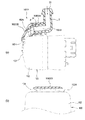
- (A) is a rear view of the vehicle (foreign matter removing device is shown in perspective)
- (b) is a side view of the rear part of the vehicle (foreign matter removing device is shown in perspective)
- (c) is a vehicle It is the elements on larger scale of the rear part.
- (A) is a figure which shows another example of the position where a foreign material removal apparatus is attached.
- It is a perspective view of a foreign substance removal device concerning a first embodiment of the present invention.
- FIG. 10 is a cross-sectional view taken along line AA in FIG. 9.
- FIG. 10 is a longitudinal sectional view taken along line BB in FIG. 9.
- (A), (b) is sectional drawing for demonstrating the bypass path
- FIG. 14 is a cross-sectional view taken along the line CC of FIG. 13.
- FIG. 15A is a cross-sectional view taken along the line DD of FIG. 14, and
- FIG. 15B is a perspective view of the joint member viewed from the lower surface side.
- (A) is a perspective view for demonstrating another modification (modification 3) of a bypass path.
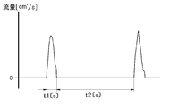
- FIG. 17 is a longitudinal sectional view taken along line EE in FIG. 16. It is a graph which shows the time change of the flow volume of the high pressure air injected from a nozzle. It is a perspective view of the foreign material removal apparatus which concerns on 3rd embodiment of this invention. It is a disassembled perspective view which shows the nozzle unit and joint member which concern on 3rd embodiment.
- FIG. 21 It is a perspective view which shows the nozzle unit attached to the vehicle-mounted camera of FIG. It is a side view which shows the attachment state of the nozzle unit with respect to a vehicle-mounted camera.
- A) is a longitudinal sectional view taken along line FF in FIG. 21, and
- (b) is a transverse sectional view taken along line GG in FIG. It is a perspective view for demonstrating the modification (modification 4) of the nozzle with which a nozzle unit is provided.
- (A) is a side view of the state in which the nozzle unit of FIG. 24 is attached to the in-vehicle camera
- (b) is a longitudinal sectional view taken along the line HH of FIG.
- the foreign matter removing device of the present invention is applied as a device that removes foreign matter such as water droplets, mud and dust adhering to the lens of the vehicle-mounted camera.
- the foreign matter removing apparatus 1 is attached to a back door 200A of the vehicle V, for example.
- the foreign matter removing apparatus 1 includes a motor 55, and a power terminal of the motor 55 is connected to a power line of the vehicle.
- the vehicle control unit (ECU) (not shown) starts shooting by an in-vehicle camera 100 described later, and the foreign matter removing device 1 is, for example, within a few seconds at the start of shooting. It is controlled to operate by a vehicle control unit (ECU).
- the in-vehicle camera 100 is a camera for confirming, for example, the rear of the vehicle V, and the lens 101 of the in-vehicle camera 100 is exposed toward the outside of the back door 200A of the vehicle V as shown in FIG. Is attached to the back door 200A.
- the in-vehicle camera 100 has an imaging unit (not shown), and the lens 101 covers the imaging unit.
- the lens 101 includes a simple translucent cover that does not converge or diffuse light.
- the foreign material removal apparatus 1 may be attached to the rear bumper 200B of the vehicle V, for example, as shown to Fig.2 (a), (b).
- the position where the in-vehicle camera 100 is attached is not limited to the rear end side of the vehicle, and may be a body panel on the front side or side side of the vehicle.
- the meaning of “attached to the body panel” means, for example, when the in-vehicle camera is attached via a vehicle cover part such as a lamp, a door knob, a mirror, or a bumper attached to the body panel. Is included as a part of these parts (as an integral part).
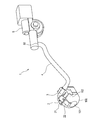
- the foreign matter removing apparatus 1 includes a nozzle unit 2, a joint member 3, a hose 4, and a high-pressure air generation unit (an example of a generation unit) 5.
- the nozzle unit 2 is configured to be detachable from the in-vehicle camera 100, and includes an attachment portion 21 and a nozzle 22.
- the nozzle unit 2 is made of, for example, resin.
- the attachment portion 21 is attached to the housing 102 of the in-vehicle camera 100 so as to cover the upper surface of the in-vehicle camera 100.
- the nozzle 22 injects high-pressure air toward the lens 101 of the in-vehicle camera 100.
- the nozzle 22 is formed integrally with the attachment portion 21, and is provided so that the tip (injection port) of the nozzle 22 faces the lens 101 when the attachment portion 21 is attached to the housing 102.
- integralally formed means that the operator can handle the nozzle 22 and the attachment portion 21 as an integral part during assembly work.
- the nozzle 22 and the attachment portion 21 may be formed with the same material and the same mold, or the nozzle 22 and the attachment portion 21 may be formed with different materials and fitted to each other.
- the nozzle unit 2 may be formed integrally.
- the joint member 3 is a member that joins the nozzle 22 and the hose 4 of the nozzle unit 2, and has one end connected to the nozzle 22 and the other end connected to the hose 4.
- the joint member 3 is made of, for example, resin.
- the hose 4 is a piping member that connects the nozzle 22 and the high-pressure air generation unit 5 together with the joint member 3. One end of the hose 4 is connected to the joint member 3, and the opposite end is connected to the discharge port 50 of the high-pressure air generation unit 5.
- the hose 4 is made of a material such as resin or rubber.
- the high-pressure air generation unit 5 is a unit for generating high-pressure air to be sent to the nozzle 22.
- the high pressure air generation unit 5 is attached to a part of the vehicle body inside the vehicle.
- the high-pressure air generation unit 5 includes a case main body 51 and a moving mechanism disposed inside the case main body 51.
- the moving direction of the piston 52 is the sending direction in the rear, which is the direction in which the air is sent out, and the accumulating force direction is in the direction opposite to the sending direction.
- the piston 52 In an initial state before high-pressure air is sent out, the piston 52 is positioned on the delivery direction side, and the rack 53 is positioned in a state where the rack portion 53a can mesh with the gear portion 54a of the pinion 54.
- the air (outside air) that has flowed into the front half portion (second space) 60b of the internal space 60 of the piston support portion 59 passes through the gap 61b along the step 61a. It flows through the inner space 60 toward a substantially half portion (first space) 60a on the rear side.
- the mounting portion 21 of the nozzle unit 2 has a substantially rectangular top plate 21A and two side plates 21B and 21C.
- the side plate 21B is provided so as to protrude from the lower surface side of the top plate 21A continuously to one end of the top plate 21A.
- the side plate 21C is located on the side opposite to the side plate 21B, and is provided so as to protrude from the lower surface side of the top plate 21A continuously to the other end of the top plate 21A.
- the side plate 21B and the side plate 21C are curved so that the respective contact portions 21D and 21E protrude slightly inward, and the lower end portion 21F and the lower end portion 21G slightly extend outward. Inclined. A material having excellent elasticity is used for the resin constituting the mounting portion 21.
- the nozzle 22 of the nozzle unit 2 has a connecting portion 22A, an extending portion 22B, and an ejection portion 22C.
- the connecting portion 22A is a portion to which the joint member 3 is connected.
- the connecting portion 22A is provided with an inflow port 23 through which high-pressure air flows.
- the extending portion 22B is a portion that connects the connecting portion 22A and the ejection portion 22C.
- the jet part 22C is a part from which high-pressure air is jetted, and is provided with a jet port 24 that opens horizontally (for example, rectangular, elliptical, etc.).
- the high-pressure air that has flowed into the inlet 23 of the connecting portion 22A is ejected from the outlet 24 of the ejecting portion 22C through the connecting portion 22A, the extending portion 22B, and the communication path formed in the ejecting portion 22C.
- the nozzle 22 is disposed at the center of the mounting portion 21 on the top plate 21A.
- the joint member 3 is formed of a cylindrical member having an L shape, and has a connecting portion 31 connected to the nozzle 22 and a connecting portion 32 connected to the hose 4.
- the connection part 32 is provided with an inflow port 33 into which high-pressure air flows.
- the connecting portion 31 is provided with an outlet 34 through which high-pressure air flows out.
- a connection path that connects the inflow port 33 and the outflow port 34 is formed in the joint member 3.
- the joint member 3 is connected to the nozzle 22 as shown in FIG. 5B by fitting the connecting portion 31 into the inlet 23 of the nozzle 22. In a state where the joint member 3 is connected to the nozzle 22, the joint member 3 can rotate about the connecting portion 31 to change the posture with respect to the nozzle 22.
- the housing 102 of the in-vehicle camera 100 is formed in a cubic shape, for example.
- the housing 102 is positioned on the opposite side of the upper surface (an example of the first surface) 102A, the right side surface (an example of the second surface) 102B continuous with one end of the upper surface 102A, and the other side of the upper surface 102A.
- the left side surface (an example of the third surface) 102C is formed in a cubic shape, for example.
- the nozzle unit 2 is attached to the in-vehicle camera 100 so that the attachment portion 21 is fitted into the housing 102 from above.
- the inner surface (an example of the opposite surface) of the top plate 21 ⁇ / b> A faces the upper surface 102 ⁇ / b> A of the housing 102.
- the top plate 21A is bonded to the upper surface 102A of the housing 102 via an adhesive member 25 such as an adhesive or a double-sided tape.
- the side plate 21B is elastically deformable in a direction away from the right side surface 102B of the housing 102, and contacts the right side surface 102B at a contact portion (an example of a first contact portion) 21D of the side plate 21B.
- the side plate 21C comes into contact with the left side surface 102C and presses the left side surface 102C at a contact portion (an example of a second contact portion) 21E.
- a contact portion an example of a second contact portion
- the nozzle 22 is disposed toward the lens 101 so that the extending portion 22B is along the shoulder on the front surface of the housing 102, and is positioned so that the jet outlet 24 of the jet portion 22C faces the center 101A of the lens 101.
- the joint member 3 is connected to the hose 4 at the connecting portion 32.
- the high-pressure air flows into the inlet 23 (see FIG. 5) of the nozzle 22 and is ejected from the ejection port 24 through the communication path.
- High-pressure air ejected from the ejection port 24 is blown toward the lens 101 of the in-vehicle camera 100. Thereby, the foreign matter adhering to the lens 101 is blown away, and the dirt of the lens 101 is eliminated.
- the camera and the nozzle are respectively attached to the vehicle body panel. It must be positioned while. In this case, an attachment error occurs in each of the camera and the nozzle, and the sum of the two errors results in a displacement of the nozzle relative to the camera lens.
- the shape of the body panel (appearance) of the vehicle is various, it is necessary to prepare a dedicated bracket depending on the manufacturer and vehicle type, and the versatility when attaching to the vehicle is low.
- the nozzle 22 is formed integrally with the attachment portion 21, and the attachment portion 21 is attached to the housing 102 of the in-vehicle camera 100. Since it is not necessary to position the nozzle 22 by attaching it to the body panel of the vehicle, the tip of the nozzle 22 can be accurately positioned with respect to the lens 101 of the in-vehicle camera 100, and the performance of removing foreign matter adhering to the lens 101 is achieved. Can be increased.
- the nozzle unit 2 is configured such that when the attachment portion 21 is attached to the housing 102 of the in-vehicle camera 100, the jet port 24 of the nozzle 22 faces the center of the lens 101. For this reason, the positioning accuracy of the nozzle 22 with respect to the lens 101 of the in-vehicle camera 100 can be further improved, and the performance of removing foreign matter can be enhanced.
- the top plate 21 ⁇ / b> A is bonded to the housing 102 with the adhesive member 25, and the side plates 21 ⁇ / b> B and 21 ⁇ / b> C are elastically deformed to come into contact with the housing 102.
- the attachment portion 21 is firmly fixed to the housing 102 by the adhesive member 25 and is fixed to the housing 102 of the in-vehicle camera 100 in a state of being deformed along the shape of the housing 102. Therefore, the jet port 24 of the nozzle 22 can be positioned more accurately with respect to the lens 101 of the in-vehicle camera 100, and the performance of removing foreign matter can be enhanced.
- the shape of the housing 102 of the in-vehicle camera 100 to which the mounting portion 21 is attached is smaller in the size of each product compared to the shape of the vehicle body panel. Since the side plates 21B and 21C can be elastically deformed and attached to cameras with slightly different left and right widths of the housing 102, it is not necessary to prepare a dedicated bracket or the like, and the foreign matter removing apparatus 1 is attached to the vehicle. Versatility can be improved.
- the joint member 3 connected to the nozzle 22 is configured so that the posture with respect to the nozzle 22 can be changed. Therefore, the joint member 3 can be connected to the hose 4 by changing the posture of the joint member 3 even when the location of the high-pressure air generating unit 5 in the vehicle varies depending on the vehicle type. Therefore, the nozzle unit 2 and the high pressure air generation unit 5 can be easily connected via the joint member 3, and the versatility when the foreign matter removing apparatus 1 is attached to the vehicle can be further improved.
- the nozzle 22 can be attached to the vehicle-mounted camera 100 via the nozzle unit 2 without using a dedicated bracket, an increase in product cost can be suppressed.
- the attachment portion 71 of the modification is different in structure of the side plate 71B and the side plate 71C from the attachment portion 21 (see FIG. 7).
- the repeated description is abbreviate
- the side plate 71B is provided so as to extend in a direction perpendicular to the top plate 21A on the lower surface side of the top plate 21A continuously from one end of the top plate 21A.
- the side plate 71C is located on the opposite side of the side plate 71B, and is provided so as to extend in a direction perpendicular to the top plate 21A on the lower surface side of the top plate 21A continuously to the other end of the top plate 21A. It has been.
- the side plate 71B and the side plate 71C can be elastically deformed in a direction away from the right side surface 102B and the left side surface 102C of the housing 102, respectively.
- the side plate 71B and the side plate 71C are provided with a convex portion 71F and a convex portion 71G at the lower end 71D and the lower end 71E, respectively.
- the convex portion 71F and the convex portion 71G are provided so as to face each other inside the side plate 71B and the side plate 71C.
- the convex part 71F and the convex part 71G are provided so that it may extend in the width direction of the side plate 71B and the side plate 71C, for example.
- the left side surface 102C and the right side surface 102B of the housing 102 are provided with a recess 102G and a recess 102F.
- the distance h from the upper surface 102A of the housing 102 to the concave portion 102G and the concave portion 102F is configured to be equal to the distance H from the lower surface of the top plate 21A of the mounting portion 71 to the convex portion 71F and the convex portion 71G.
- the mounting portion 71 of the nozzle unit 2 is engaged with the concave portion 102G and the concave portion 102F of the housing 102, respectively, with respect to the housing 102 of the in-vehicle camera 100.
- the side plate 71B and the side plate 71C are fixed in surface contact with the housing 102.
- tip of the nozzle 22 can be positioned more accurately with respect to the lens 101 of the vehicle-mounted camera 100 in the front-rear and left-right directions of the camera.
- an engagement configuration in which a convex portion is provided on the housing 102 and a concave portion is provided on the side plate may be employed.
- FIG. 9 shows the nozzle unit 2 ⁇ / b> A attached to the in-vehicle camera 100.
- 10 shows a cross-sectional view taken along the line AA in FIG. 9, and
- FIG. 11 shows a vertical cross-sectional view taken along the line BB in FIG.
- the nozzle 82 of the modified example is different from the nozzle 22 (see FIG. 6) in the structure of the ejection part 82C.
- the repeated description is abbreviate
- the nozzle unit 2 ⁇ / b> A includes a mounting portion 21 and a nozzle 82.
- the nozzle 82 has a connecting portion 22A, an extending portion 22B, and an ejection portion 82C.
- the ejection part 82C is a part from which high-pressure air is ejected, and is provided with an ejection port 24.
- the high-pressure air flowing into the inflow port 23 is ejected from the ejection port 24 through a communication path formed by the connecting portion 22A, the extending portion 22B, and the ejection portion 82C.
- the housing 102 of the in-vehicle camera 100 has a front surface (an example of the camera front surface) 102H that is continuous with one end of each of the upper surface 102A, the right side surface 102B, and the left side surface 102C.
- the front surface 102H is a planar view region when the housing 102 is viewed from the front as a single unit.
- a lens hole 102K through which the lens 101 is exposed is formed on the front surface 102H.
- the ejection part 82 ⁇ / b> C has a top wall 91 that faces the front surface 102 ⁇ / b> H of the housing 102, and two side walls 92 and 93.
- the side wall 92 is provided so as to continuously extend from the one end of the top wall 91 in a direction away from the top wall 91.
- the side wall 93 is located on the opposite side of the side wall 92, and is provided so as to continuously extend from the other end of the top wall 91 in a direction away from the top wall 91.
- the ejection portion 82 ⁇ / b> C of the nozzle 82 is configured by the top wall 91 and the side walls 92 and 93, and a wall (bottom wall) facing the top wall 91 is not formed.
- the nozzle 82 is configured such that the side walls 92 and 93 (an example of a positioning portion) of the ejection portion 82 ⁇ / b> C are in contact with the front surface 102 ⁇ / b> H of the housing 102 in a state where the attachment portion 21 is attached to the housing 102 of the in-vehicle camera 100. (See FIG. 10). When the side walls 92 and 93 are in contact with the front surface 102H, the position of the nozzle 82 with respect to the front surface 102H of the housing 102 is determined.
- a communication passage 94 surrounded by the top wall 91, the side walls 92 and 93, and the front surface 102H of the housing 102 is formed in the ejection portion 82C (see FIG. 11).
- the high-pressure air is ejected from the ejection port 24 through the communication path 94.
- the nozzle unit 2A is fixed to the housing 102 of the in-vehicle camera 100 by the mounting portion 21 and is also fixed by the side walls 92 and 93 of the nozzle 82.
- the tip of the nozzle 82 can be accurately positioned with respect to the lens 101 of the in-vehicle camera 100 not only in the left-right direction but also in the front-rear direction of the camera.
- the ejection portion 82C has no bottom wall, the thickness of the nozzle 82 can be reduced, and the increase in size of the nozzle unit 2A can be suppressed.
- FIG. 12A and 12B are cross-sectional views for explaining a bypass path formed in a nozzle included in the foreign matter removing apparatus according to the second embodiment.
- the nozzle 122 provided in the foreign matter removing apparatus according to the second embodiment includes a communication path 71 that connects the inflow port 23 and the ejection port 24, and a lower wall 72 of the extending portion 22 ⁇ / b> B.
- a bypass path 73 is formed therethrough.
- the communication path 71 includes a pipe 71a of the connecting portion 22A, pipes 71b and 71c of the extending portion 22B, and a pipe 71d of the ejection portion 22C.
- the pipe line 71b means a pipe line from the end of the pipe line 71a to a place where the bypass path 73 is formed, and the pipe line 71c is a path from the place where the bypass path 73 is formed to the beginning of the pipe line 71d.
- the cross-sectional area of the pipe 71c (the cross-sectional area of the cross section orthogonal to the flow: an example of the size of the pipe) is slightly larger than the cross-sectional area of the pipe 71b.
- the cross-sectional area of the pipe line 71d (jet port 24) is formed to be the same as the cross-sectional area of the pipe line 71c.
- the cross-sectional area of the pipe line 71a is formed larger than the cross-sectional area of the pipe line 71d.
- the inner diameter of the pipe 71 a is the same as the outer diameter of the connecting portion 31 of the joint member 3 fitted into the inflow port 23.
- the magnitude relationship of a pipe line and each opening may be prescribed
- the bypass path 73 communicates with the communication path 71 through an opening 74 formed in the lower wall 72.
- the sectional area of the bypass path 73 is formed to be the same size as the sectional area of the opening 74.
- the opening 74 is formed to be smaller than the cross-sectional area of the pipe 71d (jet port 24) and the cross-sectional area of the pipe 71b.
- the bypass path 73 is formed to have an acute angle ⁇ with respect to the lower wall 72.
- An arrow X in FIG. 12A indicates the direction in which high-pressure air flows in the communication path 71.
- the bypass path 73 is formed so as to merge in the acute angle direction from the rear with respect to the direction of the arrow X.
- the high-pressure air flows into the inflow port 23 of the nozzle 122 as shown in FIG. 12A, and is ejected from the ejection port 24 through the communication path 71 as indicated by an arrow X.
- the jet outlet 24 is formed larger than the opening 74, and the bypass passage 73 is formed in an acute angle ( ⁇ ) direction with respect to the direction in which the high pressure air flows. Sent out as indicated by X.
- the high-pressure air ejected from the ejection port 24 is blown toward the lens 101 of the in-vehicle camera 100. Thereby, the foreign matter adhering to the lens 101 is blown away, and the dirt of the lens 101 is eliminated.
- the air sucked into the high-pressure air generating unit 5 is indicated by an arrow Y in FIG. As shown, the air flows in from the bypass port 75 and is sucked into the high-pressure air generating unit 5 through the bypass path 73 and the communication path 71.
- the nozzle 122 is provided with the spout 24 and the bypass path 73 communicating with the communication path 71 via the opening 74. For this reason, even if the nozzle 24 is temporarily clogged, the outside air (air) for generating high-pressure air can be sucked through the bypass path 73. Thereby, even if the clogging occurs in the ejection port 24, high-pressure air can be generated, and the clogging of the ejection port 24 is eliminated by the generated high-pressure air, and a good ejection state of the high-pressure air is ensured. be able to.
- the opening 74 of the bypass path 73 is formed smaller than the ejection port 24 of the nozzle 122, the high-pressure air flowing toward the ejection port 24 during the injection hardly flows out from the opening 74. For this reason, even if the bypass path 73 is provided in the nozzle 122 in addition to the ejection port 24, the performance of the nozzle 122 to remove foreign matters is maintained.
- the bypass path 73 is formed at an acute angle ( ⁇ ) with respect to the direction in which the high-pressure air flows through the communication path 71 (the direction of the arrow X shown in FIG. 12A). For this reason, the high-pressure air flowing toward the jet outlet 24 during the injection hardly flows in the direction of the bypass path 73 and hardly flows out from the opening. For this reason, even if the bypass path 73 is provided in addition to the ejection port 24, the performance of removing foreign matter by the nozzle 122 is maintained.
- FIG. 13 shows a nozzle unit 2 attached to the in-vehicle camera 100 and a joint member (an example of a connecting portion) 3A connected to the nozzle 22 of the nozzle unit 2.
- FIG. 14 is a longitudinal sectional view taken along the line CC in FIG.
- FIG. 15A shows a cross-sectional view taken along the line DD in FIG. 14, and
- FIG. 15B shows a nozzle side connecting portion 31A (referred to as a nozzle connecting portion in this example) 31A of the joint member 3A from the lower surface side. A perspective view is shown.
- the bypass path 73A of Modification 2 is different from the bypass path 73 (see FIG. 12) formed through the lower wall 72 of the nozzle 122 in that it is formed in the nozzle connecting portion 31A of the joint member 3A. Yes.
- the repeated description is abbreviate
- the nozzle connecting portion 31A of the joint member 3A of this example has a rectangular cross section as shown in FIG. Further, a rectangular connecting path 81 (a path connecting the inflow port 33 and the outflow port 34) is formed in the nozzle connecting portion 31A.
- a groove 83 that forms part of the bypass path 73A is provided on the outer peripheral surface of the lower wall 82 that constitutes the nozzle connecting portion 31A.
- the groove 83 has, for example, a semicircular cross section, and is provided so as to extend in a single line in the length direction of the nozzle connecting portion 31A.
- a bypass path 73A is formed by the inner peripheral surface.
- the bypass path 73 ⁇ / b> A is connected to the communication path 71 in the nozzle 22.
- the cross-sectional area of the bypass path 73 ⁇ / b> A is formed smaller than the cross-sectional area of the ejection port 24 of the nozzle 22.
- the function and operation of the bypass path 73A are the same as those of the bypass path 73 (see FIG. 12) described in the above embodiment.
- the bypass 22A can be simply configured by connecting the nozzle 22 and the hose 4 and using the joint member 3A that is detachably provided. Further, since the bypass path 73A is smaller than the ejection port 24, the ability of the nozzle 22 to remove foreign matter is maintained even if the bypass path 73A is provided in addition to the ejection port 24 with respect to the nozzle 22. Even if the nozzle 22 is clogged, the outside air (air) can be sucked through the bypass path 73A, and high-pressure air can be generated.
- FIG. 16A shows a state where each member is not assembled
- FIG. 16B shows a state where each member is assembled
- FIG. 17 is a cross-sectional view taken along the line EE in FIG.
- the bypass path 73B of Modification 3 is formed by assembling the in-vehicle camera 100 to which the nozzle unit 2 is attached to the camera bracket 91, and is a bypass path formed through the lower wall 72 of the nozzle 122. 73 (see FIG. 12).
- the repeated description is abbreviate
- the camera bracket 91 is provided with a pipe line (an example of a connecting portion) 92 and an opening 93.
- the pipe line 92 is a pipe that allows the nozzle 22 and the joint member 3 to communicate with each other.
- the pipe line 92 has a nozzle-side connecting portion 92A at the end on the side to which the nozzle 22 is connected, and the end on the side to which the joint member 3 is connected.
- a connecting path is formed in the pipe path 92, a nozzle connecting port 94 is provided in the nozzle side connecting portion 92A, and a joint connecting port 95 is provided in the joint side connecting portion 92B.
- the opening 93 is a part in which the in-vehicle camera 100 is accommodated.
- the in-vehicle camera 100 includes a connector unit 103 provided with a power supply terminal, a signal terminal, and the like.
- the nozzle 22 is attached to the upper surface 10 ⁇ / b> A of the camera 100 with an adhesive member (for example, double-sided tape) 25.
- the nozzles 22 are attached so as to be adjusted so that the nozzles 24 of the nozzles 22 face, for example, the center point of the lens 101 of the camera 100.
- the connector 103 of the in-vehicle camera 100 is inserted into the opening 93 of the camera bracket 91.
- the inserted in-vehicle camera 100 has the lens 101 side rotated in the direction of the upper surface 100A of the in-vehicle camera 100 around the end on the connector portion 103 side, and the nozzle 22 affixed to the upper surface 100A is a conduit of the camera bracket 91 92.
- a part of the nozzle side connecting portion 92 ⁇ / b> A of the pipe line 92 is inserted into the inlet 23 of the nozzle 22.
- the engaging portion of the camera bracket 91 is engaged with the engaging portion of the in-vehicle camera 100, and the assembly is completed.
- the cross-sectional area of the nozzle connection port 94 of the nozzle side connection portion 92A is smaller than the cross-sectional area of the inflow port 23 of the connection portion 22A of the nozzle 22. For this reason, gaps 96A and 96B are formed between the outer peripheral surface of the nozzle side connecting portion 92A and the inner peripheral surface of the connecting portion 22A. This gap becomes the bypass path 73B.
- the bypass path 73 ⁇ / b> B communicates with the communication path 71 in the nozzle 22 through the opening 97 or 98.
- the cross-sectional area of the opening 97 and the cross-sectional area of the opening 98 are formed smaller than the cross-sectional area of the ejection port 24 of the nozzle 22.
- the distance d1 of the opening 97 and the distance d2 of the opening 98 are formed to be smaller than the distance d3 of the ejection port 24 of the nozzle 22.
- the function and operation of the bypass path 73B are the same as those of the bypass path 73 (see FIG. 12) described in the second embodiment.
- the bypass path 73B can be simply configured using the pipe path 92 provided in the camera bracket 91.
- the nozzle-side connecting portion 92A of the conduit 92 and the nozzle connecting port 94 of the nozzle 22 that have different maximum outer diameters and cross-sectional areas. Are inserted into each other and assembled. For this reason, when the vehicle-mounted camera 100 is assembled to the camera bracket 91, the nozzle-side coupling portion 92A and the nozzle coupling port 94 can be assembled without being in contact with each other.
- the position of the nozzle 22 with respect to 101 can be set appropriately.
- the same effects as those of the second modification are achieved.
- the high-pressure air generation unit 5 described with reference to FIG. 4 may operate as follows. Specifically, in FIG. 18, the piston 52 in the high-pressure air generating unit 5 is moved from the top dead center (the state where the end 52 ⁇ / b> A is positioned on the imaginary line L of the first space 60 a) to the bottom dead center (shown in FIG. 4). The time during which the piston 52 moves from the bottom dead center to the top dead center is defined as the exhaust time (delivery time) t1. At this time, as shown in FIG. 18, the accumulation time t2 is preferably 10 times or more of the delivery time t1.
- the piston 52 is slowly moved from the top dead center to the bottom dead center, while the movement from the bottom dead center to the top dead center is instantaneously performed, that is, sufficiently longer than the delivery time t1.
- instantaneously exhausting the air within the delivery time t1 while ensuring the reservoir time t2 even in the high-pressure air generating unit 5 where the biasing force of the biasing spring 58 is small, water droplets attached to the lens 101 are reliably moved. be able to.
- the speed of the piston 52 in the sending direction which is the moving direction for sending out air
- the speed in the direction of the retentive force which is the moving direction when inhaling air.
- the moving speed of the air in the communication passage 71 is also faster during exhaust than during intake.
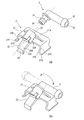
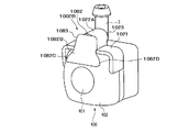
- FIG. 19 is a perspective view of a foreign matter removing apparatus according to the third embodiment of the present invention.
- the foreign matter removing apparatus 1000 includes a nozzle unit 1002, a joint member 3, a hose 4, and a high-pressure air generation unit (an example of a generation unit) 5. Since the basic configuration of the nozzle unit 1002 is the same as that of the nozzle unit 2 of the first embodiment, repeated description is omitted. In addition, parts having the same numbers as those described above have the same functions and operations, and thus repetitive description is omitted.
- the mounting portion 1021 of the nozzle unit 1002 has a substantially rectangular top plate 1021A and two side plates 1021B and 1021C.
- the side plate 1021B is provided so as to protrude from the lower surface side of the top plate 1021A continuously to one end of the top plate 1021A.
- the side plate 1021C is located on the opposite side to the side plate 1021B, and is provided so as to protrude from the lower surface side of the top plate 1021A continuously to the other end of the top plate 1021A.
- a material having excellent elasticity is used for the resin constituting the mounting portion 1021.
- the nozzle 1022 of the nozzle unit 1002 is arranged at the center of the mounting portion 1021 on the top plate 1021A.
- the nozzle 1022 has a connecting portion 1022A and a top wall 1022B (an example of a first wall portion).
- the connecting portion 1022A is a portion to which the joint member 3 is connected.
- the connecting portion 1022A is provided with an inflow port 1023 into which high-pressure air flows.
- the ceiling wall 1022B is a portion from which high-pressure air is ejected, and protrudes obliquely downward from the upper portion of the connecting portion 1022A.
- the high-pressure air flowing into the inflow port 1023 is ejected toward the lens 101 along the top wall 1022B through the connecting portion 1022A.
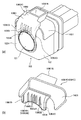
- the housing 102 of the in-vehicle camera 100 is formed in a cubic shape, for example.
- the housing 102 has an upper surface (an example of a first surface) 102A, side surfaces 102B and 102C continuous with both ends of the upper surface 102A, and a front surface (front surface of the camera) continuous with one end of each of the upper surface 102A, right side surface 102B, and left side surface 102C.
- Example) 102H The front surface 102H is a planar view region when the housing 102 is viewed from the front as a single unit.
- the top wall 1022B of the nozzle 1022 is disposed at a position facing the front surface 102H of the housing 102 in a state where the mounting portion 1021 of the nozzle unit 1002 is mounted on the housing 102 of the in-vehicle camera 100.
- the injection port of the nozzle 1022 is formed only from the top wall 1022B, and a wall (bottom wall) facing the top wall 1022B and side walls extending from both ends of the top wall 1022B are not formed.
- the nozzle 1022 is disposed toward the lens 101 so that the top wall 1022B is along the shoulder between the upper surface 102A and the upper surface 102A and the front surface 102H of the housing 102, and the tip of the top wall 1022B is The lens 101 is positioned so as to face the lens 101.
- the high-pressure air that has flowed into the inflow port 1023 of the connecting portion 1022A passes between the top wall 1022B and the upper surface 102A of the housing 102, and is ejected from between the top wall 1022B and the front surface 102H of the housing 102.
- a high-pressure air outlet is formed between the top wall 1022B and the housing 102.
- the shape of the nozzle 1022 is configured so that the high-pressure air flowing into the nozzle 1022 from the high-pressure air generation unit 5 is jetted toward the lens 101 while being applied to the top wall 1022B.
- the nozzle 1022 is formed so that the angle ⁇ formed by the connecting portion 1022A and the top wall 1022B is an obtuse angle, preferably 110 ° or more and 160 ° or less.
- the top wall 1022B has a shape that extends substantially parallel to the front surface 102H of the housing 102 of the in-vehicle camera 100 in a top view with the nozzle unit 1002 attached to the in-vehicle camera 100. No side wall or the like extending from the top wall 1022B to the front surface 102H side of the housing 102 is provided.
- the high-pressure air flows into the inlet 1023 (see FIG. 23A) of the nozzle 1022, and flows between the top wall 1022B and the front surface 102H of the housing 102.
- the high-pressure air that has flowed in between the top wall 1022 ⁇ / b> B and the front surface 102 ⁇ / b> H of the housing 102 flows along the shoulder of the front surface 102 ⁇ / b> H of the housing 102 and is blown toward the lens 101 of the in-vehicle camera 100. Thereby, the foreign matter adhering to the lens 101 is blown away, and the dirt of the lens 101 is eliminated.
- the nozzle outlet is arranged at a position facing the upper surface of the camera housing as in the conventional foreign matter removing apparatus, it is difficult to efficiently blow high-pressure air onto the lens. Further, if the nozzle tip is formed with a wall that covers the entire peripheral surface of the high-pressure air outlet, it is necessary to make the space for attaching the foreign substance removing device relatively large.
- the tip of the nozzle 1022 is formed from the top wall 1022B facing the front surface 102H of the camera 100. For this reason, since the high-pressure air sent from the high-pressure air generation unit 5 flows between the top wall 1022B and the front surface 102H of the camera housing 102 and is efficiently blown onto the lens 101, the performance of removing foreign matters can be maintained. it can. Further, the tip of the nozzle 1022 is formed only from the top wall 1022B, and the nozzle ejection portion is not formed by the wall portion covering the entire peripheral surface of the high-pressure air ejection port as in the prior art. It is simple and can reduce the thickness of the jet outlet of the nozzle 1022 to save space, and is very excellent in mounting on a vehicle.
- the shape of the nozzle 1022 is configured so that the high-pressure air flowing into the nozzle 1022 from the high-pressure air generating unit 5 is jetted toward the lens 101 while being applied to the top wall 1022B.
- high-pressure air can be rectified, and high-pressure air with an appropriate air volume can be sent to an appropriate location on the surface of the lens 101.
- FIG. 24 shows a nozzle unit 1002A attached to the in-vehicle camera 100.
- FIG. 25 (a) is a side view of the state in which the nozzle unit 1002A is attached to the in-vehicle camera 100
- FIG. 25 (b) is a longitudinal sectional view taken along the line HH in FIG. c) shows a cross-sectional view taken along the line II in FIG.
- the nozzle 1072 of the modified example 4 is different in the structure of the ejection part 1073 compared to the nozzle 1022 (see FIGS. 21, 22 and the like).
- the repeated description is abbreviate
- the nozzle unit 1002A has a mounting portion 1021 and a nozzle 1072.
- the nozzle 1072 has a connecting portion 1022A and an ejection portion 1073.
- the ejection part 1073 is a part from which high-pressure air is ejected, and the high-pressure air that has flowed into the inlet 1023 via the joint member 3 is ejected from the ejection part 1073 through the connecting part 1022A.
- the ejection portion 1073 has a top wall 1072B facing the front surface 102H of the housing 102, and two side walls 1072C and 1072D (an example of a second wall portion).
- the side wall 1072C is provided so as to continuously extend from one end of the top wall 1072B in a direction away from the top wall 1072B.
- the side wall 1072D is located on the opposite side of the side wall 1072C, and is provided so as to continuously extend from the other end of the top wall 1072B in a direction away from the top wall 1072B.
- the ejection part 1073 of the nozzle 1072 is constituted by the top wall 1072B and the side walls 1072C and 1072D, and a wall (bottom wall) facing the top wall 1072B is not formed.
- the nozzle 1072 is configured such that the side walls 1072C and 1072D of the ejection portion 1073 are in contact with the front surface 102H of the housing 102 in a state where the attachment portion 1021 is attached to the housing 102 of the in-vehicle camera 100 (FIG. 25C). reference).
- the side walls 1072C and 1072D come into contact with the front surface 102H, the position of the nozzle 1072 with respect to the front surface 102H of the housing 102 is determined.
- the ejection portion 1073 is formed with a communication passage 1074 surrounded by the top wall 1072B, the side walls 1072C and 1072D, and the front surface 102H of the housing 102 (FIG. 25 ( b) and (c)). High-pressure air is ejected from the ejection port 1075 through the communication path 1074.
- the top wall 1072B, the side walls 1072C and 1072D, and the front surface 102H of the camera housing 102 form the communication path 1074 that covers the entire peripheral surface of the high-pressure air blowing port, so that the high pressure blown from the nozzle 1072 is formed. Air can be guided to the lens 101 more efficiently.
- it is fixed to the housing 102 of the in-vehicle camera 100 by the mounting portion 1021 and positioned by contacting the side walls 1072C and 1072D of the nozzle 1072 with the front surface 102H of the housing 102.
- the tip of the nozzle 1072 can be accurately positioned with respect to the lens 101 of the in-vehicle camera 100 not only in the left-right direction but also in the front-rear direction of the in-vehicle camera 100. Further, since the ejection portion 1073 is constituted by the top wall 1072B and the side walls 1072C and 1072D and does not have a bottom wall facing the top wall 1072B, the thickness of the nozzle 1072 can be reduced and space saving can be achieved. Can also be achieved.
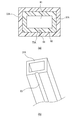
- the side walls 1072C and 1072D are configured to contact the front surface 102H of the housing 102, but the side walls 1072C and 1072D may not be configured to contact the front surface 102H. Even in this case, the high-pressure air can be efficiently guided toward the lens 101 by the top wall and the side wall. Further, as shown in FIG. 26, the top wall 1074B may be formed to have a circular arc shape in accordance with the circular arc shape of the lens 101. Thereby, high-pressure air can be uniformly guided to the entire surface of the lens 101.
- the nozzle unit 1002B has a mounting portion 1021 and a nozzle 1082.
- the nozzle 1082 has a connecting portion 1022A and an ejection portion 1083.
- the ejection part 1083 has a top wall 1082B that faces the front surface 102H of the housing 102, and side walls 1082C and 1082D that extend from both ends of the top wall 1082B toward the lens 101 side.
- the top wall 1082B is formed in a shape that is enlarged in a fan shape from the connecting portion 1022A toward the front surface of the lower lens 101.
- the high-pressure air that has flowed into the inflow port 1023 through the joint member 3 is ejected from the ejection part 1083 through the connecting part 1022A.
- the top wall 1082B is formed in a fan shape, high-pressure air can be blown substantially uniformly toward the entire outer surface of the lens 101.
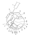
- the nozzle unit 1002C has a mounting portion 1021 and a nozzle 1092.
- the nozzle 1092 has an opening 1092A and an ejection part 1093.
- the opening portion 1092A is an opening through which a high-pressure air is introduced by inserting a hose or a joint member (not shown) that is connected to the high-pressure air generation unit 5 and sends out the high-pressure air therein.
- the ejection portion 1093 is a portion from which high-pressure air is ejected, and the high-pressure air that has flowed from the opening 1092A is ejected from the ejection port 1094 of the ejection portion 1093.
- the ejection part 1093 has a top wall 1092B facing the front surface 102H of the housing 102, and two side walls 1092C and 1092D.
- a plurality of elongated protrusions 1095 are provided in the top wall 1092B in the top wall 1092B, a plurality of elongated protrusions 1095 are provided on a surface 1092B1 (see FIG. 28B) facing the front surface 102H of the housing 102.
- the protrusion 1095 is a member for rectifying high-pressure air and blowing it to the lens 101.
- the arrangement pitch between the protrusions 1095A at the center is slightly narrower than the arrangement pitch between the protrusions 1095B on both sides and the protrusions 1095A on the inside.
- the nozzle 1092 is arranged so that the side walls 1092C and 1092D of the ejection portion 1093 are in contact with the front surface 102H of the housing 102 in a state where the attachment portion 1021 is attached to the housing 102 of the in-vehicle camera 100, and the top wall 1092B A communication path surrounded by the side walls 1092C and 1092D and the front surface 102H of the housing 102 is formed.
- the high-pressure air that has flowed in through the opening 1092A is jetted from the jet outlet 1094 toward the lens 101 while being rectified by the protrusion 1095 formed in the communication path.
- the high pressure air is more efficiently blown to the lens 101 by controlling the injection direction, the amount, the pressure, and the like of the high pressure air at the ejection portion 1093 by the protrusion 1095. Can do.
- the foreign matter removing apparatus 1,1000 in which high pressure air is generated by the high pressure air generating unit 5 and high pressure air is ejected from the nozzle 22 to remove foreign matter on the lens.
- the nozzle unit according to the embodiment and the modified example as a foreign matter removing device including a storage unit that stores the cleaning liquid and a nozzle that sprays the cleaning liquid toward the lens of the camera.
- the joint member 3 is provided as a member for joining the nozzle 22 and the hose 4 of the nozzle unit 2, but there is no need to change the posture of the hose 4 with respect to the nozzle 22.
- the hose 4 may be directly attached to the nozzle 22 without providing the joint member 3.
- this invention is not limited to embodiment mentioned above, A deformation
- the material, shape, dimension, numerical value, form, number, location, and the like of each component in the above-described embodiment are arbitrary and are not limited as long as the present invention can be achieved.
- the application to the vehicle-mounted camera is described, but the target to which the present invention is applied is not limited as long as it is a camera used outdoors.
- the target to which the present invention is applied is not limited as long as it is a camera used outdoors.
- it includes a camera attached so as to be exposed to the outside such as an aircraft, a railway, a ship, a robot, an outdoor installation, a building, and the like.
- the present invention is applicable to sensors that can be attached to a vehicle, such as LIDAE (laser radar), millimeter wave radar, and ultrasonic sensor.
- LIDAE laser radar
- millimeter wave radar millimeter wave radar
- ultrasonic sensor ultrasonic sensor
- the target part from which the foreign substance removing device removes the foreign substance is not limited to the camera lens.
- an optical lens of a sensor element a cover that covers the front surface of the optical lens, a lamp that has a part that functions as a communication window for the sensor, a cover for vehicle cover parts such as a mirror, a bumper, a grille, and a doorknob, and a sensor mounted in the vehicle compartment
- the present invention can be applied to a foreign matter removing apparatus that removes foreign matter adhering to a “partition wall” defined as a concept encompassing a vehicle window and the like in such a case.
- This partition is not limited to a transparent member (translucent), and may not be transparent in an ultrasonic sensor, a millimeter wave radar, or the like.
Abstract
This foreign matter removal device is for removing foreign matter on the lens (101) of a vehicle-mounted camera (100) attached to a vehicle such that the lens (101) of the vehicle-mounted camera (100) is exposed toward the outside of a body panel of the vehicle. The foreign matter removal device is provided with: a generation unit (5) for generating high-pressure air; and a nozzle unit (2) comprising a nozzle (22) for spraying high-pressure air toward the lens (101) and an attachment section (21) that is formed integrally with the nozzle (22) and that can be attached to the housing (102) of the vehicle-mounted camera (100). The tip of the nozzle (22) is positioned with respect to the lens (101) in a state in which the attachment section (21) is attached to the housing (102) of the vehicle-mounted camera (100).
Description
本発明は、高圧空気を噴射して異物を除去する異物除去装置および当該異物除去装置を備える車両に関する。
The present invention relates to a foreign matter removing device that ejects high pressure air to remove foreign matter, and a vehicle equipped with the foreign matter removing device.
近年、車両周囲の状況を撮影する車載カメラが搭載された車両が増えてきている。車載カメラは、撮像面であるレンズが雨や泥等で汚れてしまう場合がある。このため、従来、レンズ上に付着した水滴等の異物を除去するために、車載カメラのレンズに洗浄液や高圧空気等を吹き付けて異物を除去する異物除去装置が知られている(特許文献1参照)。
In recent years, an increasing number of vehicles are equipped with in-vehicle cameras that capture the situation around the vehicle. In a vehicle-mounted camera, a lens that is an imaging surface may become dirty due to rain or mud. For this reason, conventionally, in order to remove foreign matters such as water droplets adhering to the lens, there is known a foreign matter removing device that sprays cleaning liquid, high-pressure air or the like on the lens of the in-vehicle camera to remove the foreign matter (see Patent Document 1). ).
このような異物除去装置では、カメラのレンズに対するノズルの先端の位置決め精度が低いと、異物を除去する性能が低下してしまう場合がある。そこで、例えば、車両のボディパネルに専用のブラケットを設けて、その専用のブラケットを介してノズルがレンズに対して(具体的には、カメラのハウジングの上面に対して)位置決めされる構成が提案されている(特許文献2参照)。
In such a foreign substance removing device, if the positioning accuracy of the tip of the nozzle with respect to the camera lens is low, the performance of removing the foreign substance may deteriorate. Therefore, for example, a configuration is proposed in which a dedicated bracket is provided on the body panel of the vehicle, and the nozzle is positioned with respect to the lens (specifically, the upper surface of the camera housing) via the dedicated bracket. (See Patent Document 2).
しかしながら、車両の種類によって車両ボディの形状は様々であり、車両毎にボディパネルの形状は異なる。このため、特許文献1のように専用のブラケットを用いる方法では、車両の種類毎に専用のブラケットを準備しなければならず、異物除去装置を車両に取り付ける際の汎用性が低下してしまう。
However, the shape of the vehicle body varies depending on the type of vehicle, and the shape of the body panel varies from vehicle to vehicle. For this reason, in the method of using a dedicated bracket as in Patent Document 1, a dedicated bracket must be prepared for each type of vehicle, and versatility when attaching the foreign substance removing device to the vehicle is reduced.
また、特許文献1のように、高圧空気を噴射する噴射装置では、高圧空気を生成するためのデバイスが必要となる。通常、このような噴射装置は、ノズルの先端から外部の空気を吸い込んで装置内部で吸い込んだ空気を圧縮させる構成を有している。しかしながら、ノズルの先端が泥や塵等で詰まってしまい、高圧空気を生成することが困難となる場合がある。この場合、異物を除去する性能が低下してしまうため、ノズルの先端の詰まりに対する対策が必要となる。
Further, as in Patent Document 1, an injection device that injects high-pressure air requires a device for generating high-pressure air. Usually, such an injection device has a configuration in which external air is sucked from the tip of the nozzle and the air sucked in the device is compressed. However, the tip of the nozzle may be clogged with mud or dust, and it may be difficult to generate high-pressure air. In this case, since the performance of removing foreign matter is deteriorated, it is necessary to take measures against clogging of the nozzle tip.
また、高圧空気をカメラのレンズに吹き付ける場合に、特許文献1に記載された構成のようにカメラのハウジング上面に対向する位置にノズル吹き出し口を配置すると、高圧空気をレンズに向けて効率的に吹き付けることは困難である。また、ノズル先端部を吹き出し口の周面全体を覆うような壁部で形成すると、異物除去装置を車両に取り付ける際のスペースを比較的大きくする必要がある。
Further, when high pressure air is blown to the lens of the camera, if the nozzle outlet is disposed at a position facing the upper surface of the camera housing as in the configuration described in Patent Document 1, the high pressure air is efficiently directed toward the lens. It is difficult to spray. In addition, if the nozzle tip is formed with a wall that covers the entire peripheral surface of the outlet, it is necessary to make the space for attaching the foreign substance removing device relatively large.
そこで、本発明は、異物を除去する性能を維持しつつ、取り付ける際の汎用性を向上させ、ノズルの先端が詰まった場合であっても高圧空気を生成することが可能であって、さらに取り付ける際の省スペース化が可能な異物除去装置および当該異物除去装置を備える車両を提供することを目的とする。
Therefore, the present invention improves the versatility of attachment while maintaining the performance of removing foreign substances, and can generate high-pressure air even when the tip of the nozzle is clogged. An object of the present invention is to provide a foreign matter removing device capable of saving space and a vehicle including the foreign matter removing device.
上記目的を達成するために、本発明の異物除去装置は、
車載カメラのレンズが車両のボディパネルの外側に向けて露出した状態となるように車両に取り付けられた前記車載カメラのレンズ上の異物を除去する異物除去装置であって、
高圧空気を生成する生成部と、
前記高圧空気を前記レンズに向けて噴射するノズルと、前記ノズルと一体的に形成され、前記車載カメラのハウジングに対して取り付け可能な取付部とを有するノズルユニットと、
を備え、
前記取付部が前記ハウジングに対して取り付けられた状態において、前記ノズルの先端は前記レンズに対して位置決めされる。 In order to achieve the above object, the foreign matter removing apparatus of the present invention comprises
A foreign matter removing device for removing foreign matter on the lens of the in-vehicle camera attached to the vehicle so that the lens of the in-vehicle camera is exposed toward the outside of the body panel of the vehicle,
A generator for generating high-pressure air;
A nozzle unit having a nozzle that injects the high-pressure air toward the lens, and a mounting portion that is integrally formed with the nozzle and that can be attached to a housing of the in-vehicle camera;
With
In a state where the attachment portion is attached to the housing, the tip of the nozzle is positioned with respect to the lens.
この構成によれば、ノズルは、当該ノズルと一体的に形成された取付部によって車載カメラのハウジングに取り付けられる。このため、車両のボディパネルに取り付けるための専用のブラケットを用いることなく、ノズルの先端を車載カメラのレンズに対して精度よく位置決めすることができ、異物を除去する性能を維持することができる。また、取付部は、車両のボディパネルと比較して製品毎の形状の変化が小さい車載カメラのハウジングに対して取り付けられるため、異物除去装置を車両に取り付ける際の汎用性が向上する。
According to this configuration, the nozzle is attached to the housing of the in-vehicle camera by the attachment portion formed integrally with the nozzle. For this reason, the tip of the nozzle can be accurately positioned with respect to the lens of the in-vehicle camera without using a dedicated bracket for attaching to the body panel of the vehicle, and the performance of removing foreign matters can be maintained. In addition, since the attachment portion is attached to the housing of the in-vehicle camera in which the change in shape of each product is small compared to the body panel of the vehicle, versatility when attaching the foreign matter removing device to the vehicle is improved.
また、本発明の異物除去装置において、
前記ハウジングは、第一面と、前記第一面の一端と連続する第二面と、前記第二面とは反対側に位置するとともに前記第一面の他端と連続する第三面と、を有し、
前記取付部は、前記ハウジングに取り付けられた状態において、前記第一面と対向する対向面と、前記第二面と離れる方向に向けて弾性変形可能であるとともに前記第二面に接触する第一接触部と、前記第三面と離れる方向に向けて弾性変形可能であるとともに前記第三面に接触する第二接触部と、を有していても良い。 In the foreign matter removing apparatus of the present invention,
The housing includes a first surface, a second surface that is continuous with one end of the first surface, a third surface that is located opposite to the second surface and is continuous with the other end of the first surface, Have
In the state where the attachment portion is attached to the housing, the attachment portion is elastically deformable in a direction away from the opposing surface facing the first surface and the second surface, and is in contact with the second surface. You may have a contact part and the 2nd contact part which contacts the said 3rd surface while being elastically deformable toward the direction away from the said 3rd surface.
この構成によれば、ノズルユニットの取付部は、車載カメラのハウジングの外形に沿って変形した状態でハウジングに固定される。このため、ノズルの先端を車載カメラのレンズに対してさらに精度よく位置決めすることができる。
According to this configuration, the mounting portion of the nozzle unit is fixed to the housing while being deformed along the outer shape of the housing of the in-vehicle camera. For this reason, the tip of the nozzle can be positioned more accurately with respect to the lens of the in-vehicle camera.
また、本発明の異物除去装置において、
前記ハウジングの前記第一面と前記取付部の前記対向面とは、接着部材を介して互いに面的に接着されていても良い。 In the foreign matter removing apparatus of the present invention,
The first surface of the housing and the facing surface of the mounting portion may be bonded to each other through an adhesive member.
前記ハウジングの前記第一面と前記取付部の前記対向面とは、接着部材を介して互いに面的に接着されていても良い。 In the foreign matter removing apparatus of the present invention,
The first surface of the housing and the facing surface of the mounting portion may be bonded to each other through an adhesive member.
この構成によれば、ノズルユニットの取付部は、接着部材を介して、車載カメラのハウジングに対して強固に固定される。このため、ノズルの先端を車載カメラのレンズに対してさらに精度よく位置決めすることができる。
According to this configuration, the mounting portion of the nozzle unit is firmly fixed to the in-vehicle camera housing via the adhesive member. For this reason, the tip of the nozzle can be positioned more accurately with respect to the lens of the in-vehicle camera.
また、本発明の異物除去装置は、
前記ハウジングと前記取付部とが係合可能に構成されても良い。 The foreign matter removing apparatus of the present invention is
The housing and the attachment portion may be configured to be engageable with each other.
前記ハウジングと前記取付部とが係合可能に構成されても良い。 The foreign matter removing apparatus of the present invention is
The housing and the attachment portion may be configured to be engageable with each other.
この構成によれば、ノズルユニットの取付部は、車載カメラのハウジングに対して係合された状態で固定される。このため、ノズルの先端を車載カメラのレンズに対してさらに精度よく位置決めすることができる。
According to this configuration, the mounting portion of the nozzle unit is fixed while being engaged with the housing of the in-vehicle camera. For this reason, the tip of the nozzle can be positioned more accurately with respect to the lens of the in-vehicle camera.
また、本発明の異物除去装置において、
前記ハウジングは、前記レンズが露出するためのレンズ穴が形成されたカメラ前面を有し、
前記ノズルは、前記取付部が前記ハウジングに取り付けられた状態において、前記カメラ前面と接触して前記カメラ前面に対して位置決めされる位置決め部を有していても良い。 In the foreign matter removing apparatus of the present invention,
The housing has a camera front surface in which a lens hole for exposing the lens is formed,
The nozzle may include a positioning portion that is positioned with respect to the camera front surface in contact with the camera front surface in a state where the attachment portion is attached to the housing.
この構成によれば、ノズルの先端を車載カメラのレンズに対してカメラの前後方向において精度よく位置決めすることができる。
According to this configuration, the tip of the nozzle can be accurately positioned in the front-rear direction of the camera with respect to the lens of the in-vehicle camera.
また、本発明の異物除去装置において、
前記生成部は、前記高圧空気を排出する排出口を有し、
前記ノズルは、前記高圧空気が流入する流入口を有し、
さらに、
前記排出口と前記流入口とを接続するホースと、
前記ホースと前記ノズルとを連結するとともに、前記ノズルに対する姿勢を変更可能なジョイント部材と、
を備えていても良い。 In the foreign matter removing apparatus of the present invention,
The generator has a discharge port for discharging the high-pressure air,
The nozzle has an inlet through which the high-pressure air flows,
further,
A hose connecting the outlet and the inlet;
While connecting the hose and the nozzle, a joint member capable of changing the attitude with respect to the nozzle,
May be provided.
この構成によれば、ノズルとは別部品のジョイント部材の姿勢を変えることで、ホースの向きを変えることができ、異物除去装置を車両に取り付ける際の汎用性が向上する。
こ の According to this configuration, the orientation of the hose can be changed by changing the posture of the joint member that is a separate component from the nozzle, and the versatility when attaching the foreign matter removing device to the vehicle is improved.
また、本発明の異物除去装置において、
前記ノズルの先端は、前記レンズの中心を向くように位置決めされていても良い。 In the foreign matter removing apparatus of the present invention,
The tip of the nozzle may be positioned so as to face the center of the lens.
前記ノズルの先端は、前記レンズの中心を向くように位置決めされていても良い。 In the foreign matter removing apparatus of the present invention,
The tip of the nozzle may be positioned so as to face the center of the lens.
この構成によれば、高圧空気によりレンズ上の異物を除去する性能が向上する。
According to this configuration, the performance of removing foreign matter on the lens with high-pressure air is improved.
また、本発明の異物除去装置は、
カメラのレンズがパネル部材の外側に向けて露出した状態となるように取り付けられた前記カメラのレンズ上の異物を除去する異物除去装置であって、
高圧空気を生成する生成部と、
前記高圧空気を前記レンズに向けて噴射するノズルと、前記ノズルと一体的に形成され、前記カメラのハウジングに対して取り付け可能な取付部とを有するノズルユニットと、
を備え、
前記取付部が前記ハウジングに対して取り付けられた状態において、前記ノズルの先端は前記レンズに対して位置決めされる。 The foreign matter removing apparatus of the present invention is
A foreign matter removing device that removes foreign matter on the camera lens attached so that the camera lens is exposed to the outside of the panel member,
A generator for generating high-pressure air;
A nozzle unit having a nozzle that injects the high-pressure air toward the lens, and a mounting portion that is integrally formed with the nozzle and that can be attached to the housing of the camera;
With
In a state where the attachment portion is attached to the housing, the tip of the nozzle is positioned with respect to the lens.
この構成によれば、ノズルは、当該ノズルと一体的に形成された取付部によってカメラのハウジングに取り付けられる。このため、パネル部材に取り付けるための専用のブラケットを用いることなく、ノズルの先端をカメラのレンズに対して精度よく位置決めすることができ、異物を除去する性能を維持することができる。また、取付部は、パネル部材と比較して製品毎の形状の変化が小さいカメラのハウジングに対して取り付けられるため、汎用性が向上する。
According to this configuration, the nozzle is attached to the camera housing by the attachment portion formed integrally with the nozzle. Therefore, the tip of the nozzle can be accurately positioned with respect to the camera lens without using a dedicated bracket for attaching to the panel member, and the performance of removing foreign matter can be maintained. Moreover, since the attachment portion is attached to the camera housing in which the change in shape of each product is small compared to the panel member, versatility is improved.
また、本発明の異物除去装置は、
車載センサーと当該車載センサーの測定対象との間に介在する隔壁に付着する異物を除去するための異物除去装置であって、
高圧空気を生成する生成部と、
前記高圧空気を前記隔壁に向けて噴射するノズルと、前記ノズルと一体的に形成され、前記車載センサーのハウジングに対して取り付け可能な取付部とを有するノズルユニットと、
を備え、
前記取付部が前記ハウジングに対して取り付けられた状態において、前記ノズルの先端は前記隔壁に対して位置決めされる。 The foreign matter removing apparatus of the present invention is
A foreign matter removing device for removing foreign matter adhering to a partition wall interposed between an in-vehicle sensor and a measurement target of the in-vehicle sensor,
A generator for generating high-pressure air;
A nozzle unit having a nozzle that injects the high-pressure air toward the partition; and a mounting unit that is integrally formed with the nozzle and that can be attached to a housing of the in-vehicle sensor;
With
In a state where the attachment portion is attached to the housing, the tip of the nozzle is positioned with respect to the partition wall.
また、上記目的を達成するために、本発明の異物除去装置は、
車載カメラのレンズが車両のボディパネルの外側に向けて露出した状態となるように車両に取り付けられた前記車載カメラのレンズ上の異物を除去する異物除去装置であって、
高圧空気を生成する生成部と、
前記高圧空気を前記レンズに向けて噴射するノズルと、
を備え、
前記ノズルは、高圧空気が流入する流入口と、高圧空気が噴出される噴出口と、前記流入口と前記噴出口とを連通する連通路と、を有し、
前記連通路は、前記噴出口より小さい開口を介してバイパス経路と連通している。 In order to achieve the above object, the foreign matter removing apparatus of the present invention includes:
A foreign matter removing device for removing foreign matter on the lens of the in-vehicle camera attached to the vehicle so that the lens of the in-vehicle camera is exposed toward the outside of the body panel of the vehicle,
A generator for generating high-pressure air;
A nozzle for injecting the high-pressure air toward the lens;
With
The nozzle has an inflow port through which high-pressure air flows, a spout through which high-pressure air is ejected, and a communication path that connects the inflow port and the spout.
The communication path communicates with a bypass path through an opening smaller than the jet port.
この構成によれば、一時的にノズルの噴射口に詰まりが生じた場合であっても、バイパス経路を利用して高圧空気の生成のための吸気を行うことができる。また、バイパス経路の開口はノズルの噴射口より小さいため、噴射の際に噴射口に向けて流れる高圧空気はほとんど開口から流出せず、異物を除去する性能は維持される。
According to this configuration, even when the nozzle injection port is temporarily clogged, intake for generating high-pressure air can be performed using the bypass path. Further, since the opening of the bypass path is smaller than the nozzle injection port, the high-pressure air flowing toward the injection port during injection hardly flows out of the opening, and the performance of removing foreign matters is maintained.
また、本発明の異物除去装置において、
前記バイパス経路は、前記連通路を前記高圧空気が流れる向きに対して後方から鋭角方向に合流するように形成されていても良い。 In the foreign matter removing apparatus of the present invention,
The bypass path may be formed to join the communication path in an acute angle direction from the rear with respect to the direction in which the high-pressure air flows.
前記バイパス経路は、前記連通路を前記高圧空気が流れる向きに対して後方から鋭角方向に合流するように形成されていても良い。 In the foreign matter removing apparatus of the present invention,
The bypass path may be formed to join the communication path in an acute angle direction from the rear with respect to the direction in which the high-pressure air flows.
この構成によれば、バイパス経路が、連通路を高圧空気が流れる向きに対して鋭角に形成されている。このため、噴射の際に噴射口に向けて流れる高圧空気はほとんど開口から流出せず、異物を除去する性能は維持される。
According to this configuration, the bypass path is formed at an acute angle with respect to the direction in which the high-pressure air flows through the communication path. For this reason, the high-pressure air flowing toward the injection port during the injection hardly flows out from the opening, and the performance of removing foreign matters is maintained.
また、本発明の異物除去装置において、
前記生成部は、前記高圧空気を排出する排出口を有し、
さらに、
前記排出口と前記ノズルの前記流入口とを接続するホースと、
前記ホースと前記ノズルとを連結する連結部と、
を備え、
前記連結部の外周面に溝が設けられ、前記連結部が前記ノズルの前記流入口に嵌合された状態において、前記溝が前記バイパス経路となっていても良い。 In the foreign matter removing apparatus of the present invention,
The generator has a discharge port for discharging the high-pressure air,
further,
A hose connecting the outlet and the inlet of the nozzle;
A connecting portion for connecting the hose and the nozzle;
With
A groove may be provided on the outer peripheral surface of the connecting portion, and the groove may serve as the bypass path in a state where the connecting portion is fitted to the inlet of the nozzle.
この構成によれば、ホースとノズルとを連結する連結部を用いて簡易的にバイパス経路を構成することができる。
According to this configuration, the bypass path can be simply configured using the connecting portion that connects the hose and the nozzle.
また、本発明の異物除去装置において、
前記生成部は、前記高圧空気を排出する排出口を有し、
さらに、
前記排出口と前記ノズルの前記流入口とを接続するホースと、
前記ホースと前記ノズルとを連結する連結部と、
を備え、
前記連結部の開口は、前記ノズルの前記流入口より小さく、
前記連結部の一部が前記ノズルの前記流入口に挿入された状態において、前記連結部の外周面と前記流入口の内周面との間には隙間が形成され、当該隙間が前記バイバス経路となっていても良い。 In the foreign matter removing apparatus of the present invention,
The generator has a discharge port for discharging the high-pressure air,
further,
A hose connecting the outlet and the inlet of the nozzle;
A connecting portion for connecting the hose and the nozzle;
With
The opening of the connecting portion is smaller than the inlet of the nozzle,
In a state where a part of the connecting portion is inserted into the inlet of the nozzle, a gap is formed between the outer peripheral surface of the connecting portion and the inner peripheral surface of the inlet, and the gap is the bypass path. It may be.
この構成によれば、ホースとノズルとを連結する連結部を用いて簡易的にバイパス経路を構成することができる。
According to this configuration, the bypass path can be simply configured using the connecting portion that connects the hose and the nozzle.
また、本発明の異物除去装置は、
レンズ上の異物を除去する異物除去装置であって、
高圧空気を生成する生成部と、
前記高圧空気を前記レンズに向けて噴射するノズルと、
を備え、
前記ノズルは、高圧空気が流入する流入口と、高圧空気が噴出される噴出口と、前記流入口と前記噴出口とを連通する連通路と、を有し、
前記連通路は、前記噴出口より小さい開口を介してバイパス経路と連通している。 The foreign matter removing apparatus of the present invention is
A foreign matter removing device for removing foreign matter on a lens,
A generator for generating high-pressure air;
A nozzle for injecting the high-pressure air toward the lens;
With
The nozzle has an inflow port through which high-pressure air flows, a spout through which high-pressure air is ejected, and a communication path that connects the inflow port and the spout.
The communication path communicates with a bypass path through an opening smaller than the jet port.
この構成によれば、一時的にノズルの噴射口に詰まりが生じた場合であっても、バイパス経路を利用して高圧空気の生成のための吸気を行うことができる。また、バイパス経路の開口はノズルの噴射口より小さいため、噴射の際に噴射口に向けて流れる高圧空気はほとんど開口から流出せず、異物を除去する性能は維持される。
According to this configuration, even when the nozzle injection port is temporarily clogged, intake for generating high-pressure air can be performed using the bypass path. Further, since the opening of the bypass path is smaller than the nozzle injection port, the high-pressure air flowing toward the injection port during injection hardly flows out of the opening, and the performance of removing foreign matters is maintained.
また、本発明の異物除去装置は、
車載センサーと当該車載センサーの測定対象との間に介在する隔壁に付着する異物を除去するための異物除去装置であって、
高圧空気を生成する生成部と、
前記高圧空気を前記隔壁に向けて噴射するノズルと、
を備え、
前記ノズルは、高圧空気が流入する流入口と、高圧空気が噴出される噴出口と、前記流入口と前記噴出口とを連通する連通路と、を有し、
前記連通路は、前記噴出口より小さい開口を介してバイパス経路と連通している。 The foreign matter removing apparatus of the present invention is
A foreign matter removing device for removing foreign matter adhering to a partition wall interposed between an in-vehicle sensor and a measurement target of the in-vehicle sensor,
A generator for generating high-pressure air;
A nozzle that injects the high-pressure air toward the partition;
With
The nozzle has an inflow port through which high-pressure air flows, a spout through which high-pressure air is ejected, and a communication path that connects the inflow port and the spout.
The communication path communicates with a bypass path through an opening smaller than the jet port.
また、本発明の異物除去装置において、
前記生成部は、ピストンを有し、
前記生成部内のピストンが上死点から下死点へ移動する時間が、前記ピストンが下死点から上死点に移動する時間の10倍以上であっても良い。 In the foreign matter removing apparatus of the present invention,
The generator has a piston,
The time for the piston in the generating unit to move from the top dead center to the bottom dead center may be 10 times or more the time for the piston to move from the bottom dead center to the top dead center.
この構成によれば、生成部内のピストンは、空気を送り出す際の移動方向である送出方向の速度の方が、送出方向と反対方向であって空気を吸気する際の移動方向である溜力方向の速度よりも著しく速い。このため、連通路内の空気の移動する速度も、吸気時に比べて排気時の方が速い。これによれば、バイパス経路のバイパス機能を確保しつつ、排気時(噴射時)においてバイパス経路から高圧空気が流出する量を少なくすることができ、噴射時の異物除去性能を維持することができる。
According to this configuration, the piston in the generating unit is in the direction of the retentive force in which the speed in the sending direction, which is the moving direction when sending air, is opposite to the sending direction and is the moving direction when sucking in air. Significantly faster than For this reason, the speed at which the air in the communication path moves is also faster during exhaust than during intake. According to this, while ensuring the bypass function of the bypass path, the amount of high-pressure air flowing out from the bypass path during exhaust (injection) can be reduced, and the foreign matter removal performance during injection can be maintained. .
また、上記目的を達成するために、本発明に係る異物除去装置は、
車載カメラのレンズが車両のボディパネルの外側に向けて露出した状態となるように車両に取り付けられた前記車載カメラのレンズ上の異物を除去する異物除去装置であって、
高圧空気を生成する生成部と、
前記高圧空気を前記レンズに向けて噴射するノズルと、を備え、
前記ノズルの先端部は前記車載カメラの前面と対向する第一の壁部を備えている。 In order to achieve the above object, the foreign matter removing apparatus according to the present invention includes:
A foreign matter removing device for removing foreign matter on the lens of the in-vehicle camera attached to the vehicle so that the lens of the in-vehicle camera is exposed toward the outside of the body panel of the vehicle,
A generator for generating high-pressure air;
A nozzle for injecting the high-pressure air toward the lens,
The tip of the nozzle includes a first wall that faces the front surface of the in-vehicle camera.
上記構成によれば、ノズルの先端部は車載カメラの前面と対向する第一の壁部を備えている。これにより、生成部から送られた高圧空気が第一の壁部沿いに流れてカメラレンズに効率良く吹き付けられるため、異物を除去する性能を維持することができる。また、従来のようにノズル先端部を高圧空気の吹き出し口の周面全体を覆う壁部で形成する必要がないため、省スペースでノズル先端形状を構成することができ、車両への搭載性に優れている。
According to the above configuration, the tip of the nozzle includes the first wall portion facing the front surface of the in-vehicle camera. Thereby, since the high pressure air sent from the production | generation part flows along a 1st wall part and is efficiently sprayed on a camera lens, the performance which removes a foreign material can be maintained. In addition, since it is not necessary to form the nozzle tip with a wall that covers the entire peripheral surface of the high-pressure air outlet as in the prior art, the nozzle tip shape can be configured in a space-saving manner, making it easy to mount on a vehicle. Are better.
前記生成部から前記ノズルに流入された前記高圧空気を前記第一の壁部に当てながら前記レンズに向けて噴射させるように、前記ノズルの形状が構成されていても良い。
The shape of the nozzle may be configured such that the high-pressure air that has flowed into the nozzle from the generation unit is jetted toward the lens while being applied to the first wall portion.
上記構成によれば、高圧空気を第一の壁部に当てて送出することで、高圧空気を整流することができ、レンズ表面の適切な場所に適切な風量の高圧空気を送ることができる。
According to the above configuration, the high-pressure air can be rectified by sending the high-pressure air against the first wall portion, and high-pressure air with an appropriate air volume can be sent to an appropriate location on the lens surface.
前記ノズルの先端部は、前記第一の壁部の両側面から前記レンズに向けて延出される一対の第二の壁部を備えていても良い。
The tip of the nozzle may include a pair of second wall portions that extend from both side surfaces of the first wall portion toward the lens.
上記構成によれば、ノズルから吹き出される空気をより効率的にレンズに導くことができる。
According to the above configuration, the air blown from the nozzle can be more efficiently guided to the lens.
前記一対の第二の壁部は前記車載カメラの前面の形状に即した形状を備え、
前記一対の第二の壁部が前記前面に接するようにして前記ノズルが前記車載カメラに取り付けられていても良い。 The pair of second wall portions has a shape conforming to the shape of the front surface of the in-vehicle camera,
The nozzle may be attached to the in-vehicle camera so that the pair of second wall portions are in contact with the front surface.
前記一対の第二の壁部が前記前面に接するようにして前記ノズルが前記車載カメラに取り付けられていても良い。 The pair of second wall portions has a shape conforming to the shape of the front surface of the in-vehicle camera,
The nozzle may be attached to the in-vehicle camera so that the pair of second wall portions are in contact with the front surface.
上記構成によれば、第一の壁部と第二の壁部とカメラの前面とにより高圧空気の吹き出し口の周面全体を覆う管路を形成できるため、ノズルから吹き出される空気をより効率的にレンズに導くことができるとともに、ノズルをカメラのレンズに対して精度よく位置決めすることができる。
According to the above configuration, the first wall portion, the second wall portion, and the front surface of the camera can form a pipe line that covers the entire peripheral surface of the high-pressure air outlet, so that the air blown from the nozzle is more efficient. Therefore, the nozzle can be accurately positioned with respect to the lens of the camera.
前記第一の壁部は、前記レンズに向かって扇状に拡大された形状を備えていても良い。
The first wall portion may have a shape expanded in a fan shape toward the lens.
上記構成によれば、レンズの外表面全体に向けて略均一に高圧空気を吹き付けることができる。
According to the above configuration, high-pressure air can be sprayed substantially uniformly toward the entire outer surface of the lens.
前記第一の壁部の前記車載カメラの前面と対向する面には前記高圧空気を整流して前記レンズに吹き付けるための少なくとも一つの突起部が設けられていても良い。
The surface of the first wall facing the front surface of the in-vehicle camera may be provided with at least one protrusion for rectifying the high-pressure air and spraying it on the lens.
上記構成によれば、突起部によりノズル先端部での高圧空気の噴射方向、量、圧力等を制御してレンズにより効率的に吹き付けることができる。
According to the above configuration, the projection direction can control the injection direction, amount, pressure, and the like of the high-pressure air at the nozzle tip to efficiently blow it with the lens.
本発明の別の例に係る異物除去装置は、
車載カメラのレンズが車両のボディパネルの外側に向けて露出した状態となるように車両に取り付けられた前記車載カメラのレンズ上の異物を除去する異物除去装置であって、
洗浄液を貯蔵する貯蔵部と、
前記レンズの前面にその先端部が配置されるノズルと、を備え、
前記ノズルの先端部は前記車載カメラの前面と直接的に対向する第一の壁部と、前記第一の壁部の両側面から前記前面に向けて延出される一対の第二の壁部とを備え、
前記一対の第二の壁部が前記前面に接するようにして前記ノズルが前記車載カメラに取り付けられ、
前記第一の壁部の前記前面と対向する面には前記洗浄液を整流して前記レンズに向けて吐出するための少なくとも一つの突起部が設けられている。 A foreign matter removing apparatus according to another example of the present invention,
A foreign matter removing device for removing foreign matter on the lens of the in-vehicle camera attached to the vehicle so that the lens of the in-vehicle camera is exposed toward the outside of the body panel of the vehicle,
A storage unit for storing the cleaning liquid;
A nozzle whose tip is disposed on the front surface of the lens,
The nozzle tip has a first wall portion directly facing the front surface of the in-vehicle camera, and a pair of second wall portions extending from both side surfaces of the first wall portion toward the front surface. With
The nozzle is attached to the in-vehicle camera so that the pair of second wall portions are in contact with the front surface,
At least one protrusion for rectifying the cleaning liquid and discharging it toward the lens is provided on a surface of the first wall facing the front surface.
上記構成によれば、突起部によりノズル先端部での洗浄液の吐出方向、流量、圧力等を制御してレンズにより効率的に吹き付けることができる。
According to the above configuration, the ejection direction, the flow rate, the pressure, and the like of the cleaning liquid at the nozzle tip can be controlled by the protrusion, and the lens can be efficiently sprayed.
また、本発明の異物除去装置は、
カメラのレンズ上の異物を除去する異物除去装置であって、
高圧空気を生成する生成部と、
前記高圧空気を前記レンズに向けて噴射するノズルと、
を備え、
前記ノズルの先端部は前記レンズと対向する第一の壁部を備えている。 The foreign matter removing apparatus of the present invention is
A foreign matter removing device for removing foreign matter on a camera lens,
A generator for generating high-pressure air;
A nozzle for injecting the high-pressure air toward the lens;
With
The tip portion of the nozzle includes a first wall portion facing the lens.
この構成によれば、ノズルの先端部はレンズと対向する第一の壁部を備えている。これにより、生成部から送られた高圧空気が第一の壁部沿いに流れてレンズに効率良く吹き付けられるため、異物を除去する性能を維持することができる。また、従来のようにノズル先端部を高圧空気の吹き出し口の周面全体を覆う壁部で形成する必要がないため、省スペースでノズル先端形状を構成することができる。
According to this configuration, the tip portion of the nozzle includes the first wall portion facing the lens. Thereby, since the high pressure air sent from the production | generation part flows along the 1st wall part, and is efficiently sprayed on a lens, the performance which removes a foreign material can be maintained. In addition, since it is not necessary to form the nozzle tip portion with a wall portion covering the entire peripheral surface of the high-pressure air outlet as in the prior art, the nozzle tip shape can be configured in a space-saving manner.
また、本発明の異物除去装置は、
車載センサーと当該車載センサーの測定対象との間に介在する隔壁に付着する異物を除去するための異物除去装置であって、
高圧空気を生成する生成部と、
前記高圧空気を前記隔壁に向けて噴射するノズルと、
を備え、
前記ノズルの先端部は前記隔壁と対向する第一の壁部を備えている。 The foreign matter removing apparatus of the present invention is
A foreign matter removing device for removing foreign matter adhering to a partition wall interposed between an in-vehicle sensor and a measurement target of the in-vehicle sensor,
A generator for generating high-pressure air;
A nozzle that injects the high-pressure air toward the partition;
With
The tip of the nozzle has a first wall that faces the partition.
また、本発明の車両は、上述の異物除去装置を備えている。
Further, the vehicle of the present invention includes the above-described foreign matter removing device.
この構成によれば、例えば、車載カメラまたはセンサーのレンズが雨や泥等で汚れてしまった場合であっても、高圧空気を吹き付けてレンズ上の異物を除去することができ、車載カメラから得られる情報の精度を高めることができる。
According to this configuration, for example, even when the lens of the in-vehicle camera or sensor is soiled with rain or mud, the foreign matter on the lens can be removed by blowing high-pressure air. The accuracy of the information obtained can be increased.
本発明の異物除去装置および当該異物除去装置を備える車両によれば、異物を除去する性能を維持しつつ、当該異物除去装置を車両に取り付ける際の汎用性を向上させることができる。また、ノズルの先端が詰まった場合であっても高圧空気を生成することができるとともに、車両に取り付ける際の省スペース化が可能となる。
According to the foreign matter removing device of the present invention and the vehicle equipped with the foreign matter removing device, it is possible to improve versatility when attaching the foreign matter removing device to the vehicle while maintaining the performance of removing the foreign matter. Moreover, even when the tip of the nozzle is clogged, high-pressure air can be generated, and space can be saved when the nozzle is attached to the vehicle.
以下、本発明に係る実施形態の一例について、図面を参照して詳細に説明する。
本発明の異物除去装置は、車載カメラのレンズに付着する水滴や泥や塵埃等の異物を除去する装置として適用される。 Hereinafter, an example of an embodiment according to the present invention will be described in detail with reference to the drawings.
The foreign matter removing device of the present invention is applied as a device that removes foreign matter such as water droplets, mud and dust adhering to the lens of the vehicle-mounted camera.
図1(a),(b)に示すように、異物除去装置1は、例えば車両Vのバックドア200Aに取り付けられる。異物除去装置1は、モータ55を備えており、モータ55の電源端子が車両の電源ラインに接続されている。例えば、車両Vのギアがリバースに入ったことをトリガーとして、図示せぬ車両制御部(ECU)により後述する車載カメラ100による撮影が開始され、例えば撮影開始時の数秒間に異物除去装置1が車両制御部(ECU)により動作するように制御される。
1 (a) and 1 (b), the foreign matter removing apparatus 1 is attached to a back door 200A of the vehicle V, for example. The foreign matter removing apparatus 1 includes a motor 55, and a power terminal of the motor 55 is connected to a power line of the vehicle. For example, when the gear of the vehicle V enters reverse, the vehicle control unit (ECU) (not shown) starts shooting by an in-vehicle camera 100 described later, and the foreign matter removing device 1 is, for example, within a few seconds at the start of shooting. It is controlled to operate by a vehicle control unit (ECU).
車載カメラ100は、車両Vの例えば後方を確認するためのカメラであり、図1(c)に示すように、車載カメラ100のレンズ101が車両Vのバックドア200Aの外側に向けて露出した状態となるようにバックドア200Aに取り付けられている。車載カメラ100は、撮像部(図示省略)を有し、レンズ101は撮像部を覆っている。レンズ101としては、光の収束や拡散をしない単なる透光性カバーも本例のレンズに含まれる。
The in-vehicle camera 100 is a camera for confirming, for example, the rear of the vehicle V, and the lens 101 of the in-vehicle camera 100 is exposed toward the outside of the back door 200A of the vehicle V as shown in FIG. Is attached to the back door 200A. The in-vehicle camera 100 has an imaging unit (not shown), and the lens 101 covers the imaging unit. The lens 101 includes a simple translucent cover that does not converge or diffuse light.
なお、異物除去装置1は、図2(a),(b)に示すように、例えば車両Vのリアバンパー200Bに取付けられても良い。なお、車載カメラ100が取り付けられる位置は,車両の後端側に限定されず、車両の前方側や側方側等のボディパネルであっても良い。また、本例で、「ボディパネルに取り付けられる」の意味は、例えば、車載カメラがボディパネルに取り付けられたランプ、ドアノブ、ミラー、バンパー等の車両表装部品を介して取り付けられる場合や、車載カメラがこれらの部品の一部として(一体物として)搭載されている場合も含む。
In addition, the foreign material removal apparatus 1 may be attached to the rear bumper 200B of the vehicle V, for example, as shown to Fig.2 (a), (b). The position where the in-vehicle camera 100 is attached is not limited to the rear end side of the vehicle, and may be a body panel on the front side or side side of the vehicle. In addition, in this example, the meaning of “attached to the body panel” means, for example, when the in-vehicle camera is attached via a vehicle cover part such as a lamp, a door knob, a mirror, or a bumper attached to the body panel. Is included as a part of these parts (as an integral part).
(第一実施形態)
図3に示すように、異物除去装置1は、ノズルユニット2と、ジョイント部材3と、ホース4と、高圧空気生成ユニット(生成部の一例)5とを備えている。 (First embodiment)
As shown in FIG. 3, the foreignmatter removing apparatus 1 includes a nozzle unit 2, a joint member 3, a hose 4, and a high-pressure air generation unit (an example of a generation unit) 5.
図3に示すように、異物除去装置1は、ノズルユニット2と、ジョイント部材3と、ホース4と、高圧空気生成ユニット(生成部の一例)5とを備えている。 (First embodiment)
As shown in FIG. 3, the foreign
ノズルユニット2は、車載カメラ100に対して着脱可能に構成されており、取付部21と、ノズル22とを有している。ノズルユニット2は、例えば樹脂を材料として形成されている。
The nozzle unit 2 is configured to be detachable from the in-vehicle camera 100, and includes an attachment portion 21 and a nozzle 22. The nozzle unit 2 is made of, for example, resin.
取付部21は、車載カメラ100の上面を覆うようにして車載カメラ100のハウジング102に取り付けられる。ノズル22は、高圧空気を車載カメラ100のレンズ101に向けて噴射する。ノズル22は、取付部21と一体的に形成されており、取付部21がハウジング102に取り付けられた際に、ノズル22の先端(噴射口)がレンズ101を向くように設けられている。ここで、「一体的に形成され」とは、ノズル22と取付部21とを作業者が組立作業時に一体の部品として取り扱うことが可能に構成されることを意味する。具体的には、例えば、ノズル22と取付部21とを、同一材料で同一金型で成形しても良いし、ノズル22と取付部21とを別々の材料でそれぞれ成形して、互いに嵌め合わせて一体的に形成して、ノズルユニット2を構成しても良い。
The attachment portion 21 is attached to the housing 102 of the in-vehicle camera 100 so as to cover the upper surface of the in-vehicle camera 100. The nozzle 22 injects high-pressure air toward the lens 101 of the in-vehicle camera 100. The nozzle 22 is formed integrally with the attachment portion 21, and is provided so that the tip (injection port) of the nozzle 22 faces the lens 101 when the attachment portion 21 is attached to the housing 102. Here, “integrally formed” means that the operator can handle the nozzle 22 and the attachment portion 21 as an integral part during assembly work. Specifically, for example, the nozzle 22 and the attachment portion 21 may be formed with the same material and the same mold, or the nozzle 22 and the attachment portion 21 may be formed with different materials and fitted to each other. Alternatively, the nozzle unit 2 may be formed integrally.
ジョイント部材3は、ノズルユニット2のノズル22とホース4とを接合する部材であり、一方側の端部がノズル22と連結され、反対側の端部がホース4と連結されている。ジョイント部材3は、例えば樹脂を材料として形成されている。
The joint member 3 is a member that joins the nozzle 22 and the hose 4 of the nozzle unit 2, and has one end connected to the nozzle 22 and the other end connected to the hose 4. The joint member 3 is made of, for example, resin.
ホース4は、ジョイント部材3とともに、ノズル22と高圧空気生成ユニット5とを接続する配管部材である。ホース4は、一方側の端部がジョイント部材3に連結され、反対側の端部が高圧空気生成ユニット5の排出口50に連結されている。ホース4は、例えば樹脂やゴム等の材料で形成されている。
The hose 4 is a piping member that connects the nozzle 22 and the high-pressure air generation unit 5 together with the joint member 3. One end of the hose 4 is connected to the joint member 3, and the opposite end is connected to the discharge port 50 of the high-pressure air generation unit 5. The hose 4 is made of a material such as resin or rubber.
高圧空気生成ユニット5は、ノズル22に送出する高圧空気を生成するためのユニットである。高圧空気生成ユニット5は、車両の内部において車体の一部に取り付けられる。
The high-pressure air generation unit 5 is a unit for generating high-pressure air to be sent to the nozzle 22. The high pressure air generation unit 5 is attached to a part of the vehicle body inside the vehicle.
図4に示すように、高圧空気生成ユニット5は、ケース本体51と、ケース本体51の内部に配置された移動機構とを有している。高圧空気生成ユニット5において、ピストン52の移動方向は、空気を送り出す方向である後方が送出方向とされ、送出方向と反対方向である前方が溜力方向とされている。
As shown in FIG. 4, the high-pressure air generation unit 5 includes a case main body 51 and a moving mechanism disposed inside the case main body 51. In the high-pressure air generation unit 5, the moving direction of the piston 52 is the sending direction in the rear, which is the direction in which the air is sent out, and the accumulating force direction is in the direction opposite to the sending direction.
高圧空気が送り出される前の初期状態では、ピストン52が送出方向側に位置され、ラック53はラック部53aがピニオン54のギヤ部54aに噛合可能な状態で位置される。
In an initial state before high-pressure air is sent out, the piston 52 is positioned on the delivery direction side, and the rack 53 is positioned in a state where the rack portion 53a can mesh with the gear portion 54a of the pinion 54.
モータ(駆動源)55の駆動が開始され、モータ55の駆動力がウォーム56を介してウォームホイール57に伝達されると、ピニオン54のギヤ部54aがラック53のラック部53aに噛合される。このため、ラック53は、ピニオン54の回転に伴って付勢バネ58の付勢力に反して溜力方向へ移動されていく。ラック53が溜力方向へ移動されていくと、所定の位置でギヤ部54aとラック部53aの噛合が解除される。ギヤ部54aとラック部53aの噛合が解除された位置(図4に示す位置)がピストン52の下死点とされる。ピストン52が下死点に位置された状態では、ピストン支持部59の内部空間60における前側略半分の部分(第2の空間)60bに流入された空気(外気)が段差61aに沿い隙間61bを通って内部空間60における後側略半分の部分(第1の空間)60aへ向けて流動される。
When driving of the motor (drive source) 55 is started and the driving force of the motor 55 is transmitted to the worm wheel 57 via the worm 56, the gear portion 54a of the pinion 54 is engaged with the rack portion 53a of the rack 53. For this reason, the rack 53 is moved in the direction of the retraction force against the urging force of the urging spring 58 as the pinion 54 rotates. As the rack 53 is moved in the direction of the reservoir force, the gear portion 54a and the rack portion 53a are disengaged at a predetermined position. The position where the meshing between the gear portion 54a and the rack portion 53a is released (the position shown in FIG. 4) is the bottom dead center of the piston 52. In the state where the piston 52 is located at the bottom dead center, the air (outside air) that has flowed into the front half portion (second space) 60b of the internal space 60 of the piston support portion 59 passes through the gap 61b along the step 61a. It flows through the inner space 60 toward a substantially half portion (first space) 60a on the rear side.
ピストン52が下死点まで移動されると、ギヤ部54aとラック部53aの噛合が解除され、ピストン52が付勢バネ58の付勢力によって溜力方向への移動速度より高速で送出方向へ移動される。これにより、第2の空間60bから第1の空間60aに流動された空気が第1の空間60aから連結突部62の排出口50を通ってホース4を介しノズルユニット2のノズル22へ向けて送出される。このとき、排出口50の径がピストン支持部59の径よりも小さく形成されているため、第1の空間60aから排出口50を通って排出される空気は圧縮されて高圧空気となって送出される。
When the piston 52 is moved to the bottom dead center, the gear portion 54a and the rack portion 53a are disengaged, and the piston 52 is moved in the delivery direction at a higher speed than the moving speed in the direction of stored force by the biasing force of the biasing spring 58. Is done. As a result, air that has flowed from the second space 60b to the first space 60a passes from the first space 60a to the nozzle 22 of the nozzle unit 2 via the hose 4 through the discharge port 50 of the connecting protrusion 62. Sent out. At this time, since the diameter of the discharge port 50 is smaller than the diameter of the piston support portion 59, the air discharged from the first space 60a through the discharge port 50 is compressed and sent as high-pressure air. Is done.
図5(a)に示すように、ノズルユニット2の取付部21は、略長方形状の天板21Aと、2つの側面板21B,21Cとを有している。側面板21Bは、天板21Aの一方側の端部に連続して天板21Aの下面側に張り出すように設けられている。側面板21Cは、側面板21Bとは反対側に位置し、天板21Aの他方側の端部に連続して天板21Aの下面側に張り出すように設けられている。また、側面板21B及び側面板21Cは、それぞれの接触部21D及び接触部21Eが内側へ僅かに突出するように湾曲して形成され、下端部21F及び下端部21Gが外側へ僅かに広がるように傾斜して形成されている。取付部21を構成する樹脂には、弾性に優れた材料が用いられている。
As shown in FIG. 5 (a), the mounting portion 21 of the nozzle unit 2 has a substantially rectangular top plate 21A and two side plates 21B and 21C. The side plate 21B is provided so as to protrude from the lower surface side of the top plate 21A continuously to one end of the top plate 21A. The side plate 21C is located on the side opposite to the side plate 21B, and is provided so as to protrude from the lower surface side of the top plate 21A continuously to the other end of the top plate 21A. Further, the side plate 21B and the side plate 21C are curved so that the respective contact portions 21D and 21E protrude slightly inward, and the lower end portion 21F and the lower end portion 21G slightly extend outward. Inclined. A material having excellent elasticity is used for the resin constituting the mounting portion 21.
ノズルユニット2のノズル22は、連結部22Aと、延伸部22Bと、噴出部22Cとを有している。連結部22Aは、ジョイント部材3が連結される部分である。連結部22Aには、高圧空気が流入する流入口23が設けられている。延伸部22Bは、連結部22Aと噴出部22Cとを連通する部分である。噴出部22Cは、高圧空気が噴出される部分であり、横長(例えば、長方形、楕円形等)に開口する噴出口24が設けられている。連結部22Aの流入口23に流入した高圧空気は、連結部22A、延伸部22B、及び噴出部22C内に形成されている連通路を通って噴出部22Cの噴出口24から噴出される。ノズル22は、取付部21の天板21A上における中央部に配置されている。
The nozzle 22 of the nozzle unit 2 has a connecting portion 22A, an extending portion 22B, and an ejection portion 22C. The connecting portion 22A is a portion to which the joint member 3 is connected. The connecting portion 22A is provided with an inflow port 23 through which high-pressure air flows. The extending portion 22B is a portion that connects the connecting portion 22A and the ejection portion 22C. The jet part 22C is a part from which high-pressure air is jetted, and is provided with a jet port 24 that opens horizontally (for example, rectangular, elliptical, etc.). The high-pressure air that has flowed into the inlet 23 of the connecting portion 22A is ejected from the outlet 24 of the ejecting portion 22C through the connecting portion 22A, the extending portion 22B, and the communication path formed in the ejecting portion 22C. The nozzle 22 is disposed at the center of the mounting portion 21 on the top plate 21A.
ジョイント部材3は、L字状を有した筒部材で形成されており、ノズル22と連結される連結部31と、ホース4と連結される連結部32とを有している。連結部32には、高圧空気が流入する流入口33が設けられている。連結部31には、高圧空気が流出される流出口34が設けられている。ジョイント部材3内には、流入口33と流出口34とを連結する連結路が形成されている。
The joint member 3 is formed of a cylindrical member having an L shape, and has a connecting portion 31 connected to the nozzle 22 and a connecting portion 32 connected to the hose 4. The connection part 32 is provided with an inflow port 33 into which high-pressure air flows. The connecting portion 31 is provided with an outlet 34 through which high-pressure air flows out. A connection path that connects the inflow port 33 and the outflow port 34 is formed in the joint member 3.
ジョイント部材3は、連結部31がノズル22の流入口23に嵌め込まれることによって、図5(b)に示すように、ノズル22と連結される。ジョイント部材3は、ノズル22と連結された状態において、連結部31を軸として回転してノズル22に対する姿勢を変更可能とされている。
The joint member 3 is connected to the nozzle 22 as shown in FIG. 5B by fitting the connecting portion 31 into the inlet 23 of the nozzle 22. In a state where the joint member 3 is connected to the nozzle 22, the joint member 3 can rotate about the connecting portion 31 to change the posture with respect to the nozzle 22.
図6,図7に示すように、車載カメラ100のハウジング102は、例えば立方体の形状に形成されている。ハウジング102は、上面(第一面の一例)102Aと、上面102Aの一端と連続する右側面(第二面の一例)102Bと、右側面102Bとは反対側に位置し、上面102Aの他端と連続する左側面(第三面の一例)102Cとを有している。
As shown in FIGS. 6 and 7, the housing 102 of the in-vehicle camera 100 is formed in a cubic shape, for example. The housing 102 is positioned on the opposite side of the upper surface (an example of the first surface) 102A, the right side surface (an example of the second surface) 102B continuous with one end of the upper surface 102A, and the other side of the upper surface 102A. And the left side surface (an example of the third surface) 102C.
ノズルユニット2は、車載カメラ100に対して上方側から取付部21がハウジング102に嵌め込まれるようにして取り付けられる。取付部21は、ハウジング102に取り付けられた状態において、天板21Aの内面(対向面の一例)がハウジング102の上面102Aと対向する。天板21Aは、接着剤や両面テープ等の接着部材25を介してハウジング102の上面102Aに接着される。側面板21Bは、ハウジング102の右側面102Bと離れる方向に向けて弾性変形可能であり、側面板21Bの接触部(第一接触部の一例)21Dにおいて右側面102Bに接触し、右側面102Bを押圧する。同様に、側面板21Cは、接触部(第二接触部の一例)21Eにおいて左側面102Cに接触し、左側面102Cを押圧する。このように、取付部21の側面板21B,側面板21Cは、ハウジング102を左右両側から挟み込む。
The nozzle unit 2 is attached to the in-vehicle camera 100 so that the attachment portion 21 is fitted into the housing 102 from above. In the state where the attachment portion 21 is attached to the housing 102, the inner surface (an example of the opposite surface) of the top plate 21 </ b> A faces the upper surface 102 </ b> A of the housing 102. The top plate 21A is bonded to the upper surface 102A of the housing 102 via an adhesive member 25 such as an adhesive or a double-sided tape. The side plate 21B is elastically deformable in a direction away from the right side surface 102B of the housing 102, and contacts the right side surface 102B at a contact portion (an example of a first contact portion) 21D of the side plate 21B. Press. Similarly, the side plate 21C comes into contact with the left side surface 102C and presses the left side surface 102C at a contact portion (an example of a second contact portion) 21E. As described above, the side plate 21B and the side plate 21C of the mounting portion 21 sandwich the housing 102 from the left and right sides.
ノズル22は、延伸部22Bがハウジング102の前面の肩部に沿うようにレンズ101に向けて配置され、噴出部22Cの噴出口24がレンズ101の中心101Aを向くように位置決めされている。また、ジョイント部材3は、連結部32がホース4に連結される。
The nozzle 22 is disposed toward the lens 101 so that the extending portion 22B is along the shoulder on the front surface of the housing 102, and is positioned so that the jet outlet 24 of the jet portion 22C faces the center 101A of the lens 101. The joint member 3 is connected to the hose 4 at the connecting portion 32.
次に、異物除去装置1の動作について説明する。
高圧空気生成ユニット5においてモータ55の駆動が開始されると、先ず、高圧空気を生成するための空気(外気)が吸い込まれる。空気は、ノズル22の噴出口24から高圧空気生成ユニット5へ吸い込まれる。吸い込まれた空気は、付勢バネ58の付勢力によるピストン運動により、高圧空気生成ユニット5の排出口50からホース4へ高圧空気となって送出される。高圧空気は、ホース4からジョイント部材3を通ってノズルユニット2のノズル22へ送出される。 Next, the operation of the foreignmatter removing apparatus 1 will be described.
When driving of themotor 55 is started in the high-pressure air generation unit 5, first, air (outside air) for generating high-pressure air is sucked. Air is sucked into the high-pressure air generation unit 5 from the nozzle 24 of the nozzle 22. The sucked air is sent out as high-pressure air from the discharge port 50 of the high-pressure air generation unit 5 to the hose 4 by the piston movement by the urging force of the urging spring 58. The high-pressure air is sent from the hose 4 through the joint member 3 to the nozzle 22 of the nozzle unit 2.
高圧空気生成ユニット5においてモータ55の駆動が開始されると、先ず、高圧空気を生成するための空気(外気)が吸い込まれる。空気は、ノズル22の噴出口24から高圧空気生成ユニット5へ吸い込まれる。吸い込まれた空気は、付勢バネ58の付勢力によるピストン運動により、高圧空気生成ユニット5の排出口50からホース4へ高圧空気となって送出される。高圧空気は、ホース4からジョイント部材3を通ってノズルユニット2のノズル22へ送出される。 Next, the operation of the foreign
When driving of the
高圧空気は、ノズル22の流入口23(図5参照)に流入され、連通路を通って噴出口24から噴出される。噴出口24から噴出された高圧空気は、車載カメラ100のレンズ101に向けて吹き付けられる。これにより、レンズ101に付着されている異物が吹き飛ばされてレンズ101の汚れが解消される。
The high-pressure air flows into the inlet 23 (see FIG. 5) of the nozzle 22 and is ejected from the ejection port 24 through the communication path. High-pressure air ejected from the ejection port 24 is blown toward the lens 101 of the in-vehicle camera 100. Thereby, the foreign matter adhering to the lens 101 is blown away, and the dirt of the lens 101 is eliminated.
ところで、従来の異物除去装置のように専用のブラケットを介して異物除去装置を車両のパネルに取り付けて、カメラレンズに対するノズルの位置決めを行う構成では、カメラとノズルとをそれぞれ車両のボディパネルに取り付けながら位置決めをしなければならない。この場合、カメラにもノズルにもそれぞれ取付誤差が生じ、両誤差を足し合わせた分がカメラレンズに対するノズルの位置ズレとなって発生する。また、車両のボディパネル(外観)の形状は様々であるため、メーカ及び車種によっても専用のブラケットを準備する必要があり車両に取り付ける際の汎用性が低いものであった。
By the way, in the configuration in which the foreign substance removing device is attached to the vehicle panel via a dedicated bracket and the nozzle is positioned with respect to the camera lens as in the conventional foreign matter removing device, the camera and the nozzle are respectively attached to the vehicle body panel. It must be positioned while. In this case, an attachment error occurs in each of the camera and the nozzle, and the sum of the two errors results in a displacement of the nozzle relative to the camera lens. Moreover, since the shape of the body panel (appearance) of the vehicle is various, it is necessary to prepare a dedicated bracket depending on the manufacturer and vehicle type, and the versatility when attaching to the vehicle is low.
これに対して、本実施形態の異物除去装置1によれば、ノズル22は、取付部21と一体に形成されており、取付部21が車載カメラ100のハウジング102に取り付けられる。ノズル22を車両のボディパネルに取り付けて位置決めする必要がないため、ノズル22の先端を車載カメラ100のレンズ101に対して精度よく位置決めすることができ、レンズ101に付着した異物を除去する性能を高めることができる。
On the other hand, according to the foreign matter removing apparatus 1 of the present embodiment, the nozzle 22 is formed integrally with the attachment portion 21, and the attachment portion 21 is attached to the housing 102 of the in-vehicle camera 100. Since it is not necessary to position the nozzle 22 by attaching it to the body panel of the vehicle, the tip of the nozzle 22 can be accurately positioned with respect to the lens 101 of the in-vehicle camera 100, and the performance of removing foreign matter adhering to the lens 101 is achieved. Can be increased.
また、ノズルユニット2は、取付部21が車載カメラ100のハウジング102に取り付けられると、ノズル22の噴出口24がレンズ101の中心を向くように構成されている。このため、車載カメラ100のレンズ101に対するノズル22の位置決め精度をさらに向上させることができ、異物を除去する性能を高めることができる。
In addition, the nozzle unit 2 is configured such that when the attachment portion 21 is attached to the housing 102 of the in-vehicle camera 100, the jet port 24 of the nozzle 22 faces the center of the lens 101. For this reason, the positioning accuracy of the nozzle 22 with respect to the lens 101 of the in-vehicle camera 100 can be further improved, and the performance of removing foreign matter can be enhanced.
また、ノズルユニット2の取付部21は、天板21Aが接着部材25でハウジング102に接着され、側面板21B,21Cが弾性変形してハウジング102に接触される。このため、取付部21は、接着部材25で強固にハウジング102に固定されるとともに、ハウジング102の形状に沿って変形した状態で車載カメラ100のハウジング102に固定される。したがって、ノズル22の噴出口24を車載カメラ100のレンズ101に対してさらに精度よく位置決めすることができ、異物を除去する性能を高めることができる。
Further, in the mounting portion 21 of the nozzle unit 2, the top plate 21 </ b> A is bonded to the housing 102 with the adhesive member 25, and the side plates 21 </ b> B and 21 </ b> C are elastically deformed to come into contact with the housing 102. For this reason, the attachment portion 21 is firmly fixed to the housing 102 by the adhesive member 25 and is fixed to the housing 102 of the in-vehicle camera 100 in a state of being deformed along the shape of the housing 102. Therefore, the jet port 24 of the nozzle 22 can be positioned more accurately with respect to the lens 101 of the in-vehicle camera 100, and the performance of removing foreign matter can be enhanced.
また、取付部21が取り付けられる車載カメラ100のハウジング102の形状は、車両のボディパネルの形状と比較すると、製品毎の大きさの相違が小さい。ハウジング102の左右幅が多少異なったカメラに対しても、側面板21B,21Cが弾性変形して取付可能であるため、専用のブラケット等を準備する必要がなく、異物除去装置1を車両に取り付ける際の汎用性を向上させることができる。
Also, the shape of the housing 102 of the in-vehicle camera 100 to which the mounting portion 21 is attached is smaller in the size of each product compared to the shape of the vehicle body panel. Since the side plates 21B and 21C can be elastically deformed and attached to cameras with slightly different left and right widths of the housing 102, it is not necessary to prepare a dedicated bracket or the like, and the foreign matter removing apparatus 1 is attached to the vehicle. Versatility can be improved.
また、ノズル22と連結されたジョイント部材3は、ノズル22に対する姿勢を変更可能に構成されている。このため、車両における高圧空気生成ユニット5の配置場所が車種によって異なる場合であってもジョイント部材3の姿勢を変えることでジョイント部材3をホース4に接続することができる。したがって、ジョイント部材3を介してノズルユニット2と高圧空気生成ユニット5とを容易に連結することができ、異物除去装置1を車両に取り付ける際の汎用性をさらに向上させることができる。
Further, the joint member 3 connected to the nozzle 22 is configured so that the posture with respect to the nozzle 22 can be changed. Therefore, the joint member 3 can be connected to the hose 4 by changing the posture of the joint member 3 even when the location of the high-pressure air generating unit 5 in the vehicle varies depending on the vehicle type. Therefore, the nozzle unit 2 and the high pressure air generation unit 5 can be easily connected via the joint member 3, and the versatility when the foreign matter removing apparatus 1 is attached to the vehicle can be further improved.
また、専用のブラケットを用いることなくノズルユニット2を介してノズル22を車載カメラ100に取り付けることができるので、製品コストの増加を抑制することができる。
Moreover, since the nozzle 22 can be attached to the vehicle-mounted camera 100 via the nozzle unit 2 without using a dedicated bracket, an increase in product cost can be suppressed.
次に、上述した形態における取付部21の変形例について図8を参照して説明する。
図8(a)に示すように、変形例の取付部71は、取付部21(図7参照)と比較すると、側面板71B,側面板71Cの構造が相違している。なお、上述した形態と同一番号を付した部分については、同じ機能および動作であるため、繰り返しとなる説明は省略する。 Next, a modified example of the mountingportion 21 in the above-described embodiment will be described with reference to FIG.
As shown in FIG. 8A, theattachment portion 71 of the modification is different in structure of the side plate 71B and the side plate 71C from the attachment portion 21 (see FIG. 7). In addition, about the part which attached | subjected the same number as the form mentioned above, since it is the same function and operation | movement, the repeated description is abbreviate | omitted.
図8(a)に示すように、変形例の取付部71は、取付部21(図7参照)と比較すると、側面板71B,側面板71Cの構造が相違している。なお、上述した形態と同一番号を付した部分については、同じ機能および動作であるため、繰り返しとなる説明は省略する。 Next, a modified example of the mounting
As shown in FIG. 8A, the
側面板71Bは、天板21Aの一方側の端部に連続して天板21Aの下面側に天板21Aに対して垂直方向へ張り出すように設けられている。側面板71Cは、側面板71Bとは反対側に位置し、天板21Aの他方側の端部に連続して天板21Aの下面側に天板21Aに対して垂直方向へ張り出すように設けられている。側面板71B及び側面板71Cは、それぞれハウジング102の右側面102B及び左側面102Cと離れる方向に向けて弾性変形可能とされている。
The side plate 71B is provided so as to extend in a direction perpendicular to the top plate 21A on the lower surface side of the top plate 21A continuously from one end of the top plate 21A. The side plate 71C is located on the opposite side of the side plate 71B, and is provided so as to extend in a direction perpendicular to the top plate 21A on the lower surface side of the top plate 21A continuously to the other end of the top plate 21A. It has been. The side plate 71B and the side plate 71C can be elastically deformed in a direction away from the right side surface 102B and the left side surface 102C of the housing 102, respectively.
側面板71B及び側面板71Cには、それぞれの下端部71D及び下端部71Eに凸部71F及び凸部71Gが設けられている。凸部71F及び凸部71Gは、側面板71B及び側面板71Cの内側に相互に向き合うように設けられている。また、凸部71F及び凸部71Gは、例えば側面板71B及び側面板71Cの幅方向へ一条に延在するように設けられている。
The side plate 71B and the side plate 71C are provided with a convex portion 71F and a convex portion 71G at the lower end 71D and the lower end 71E, respectively. The convex portion 71F and the convex portion 71G are provided so as to face each other inside the side plate 71B and the side plate 71C. Moreover, the convex part 71F and the convex part 71G are provided so that it may extend in the width direction of the side plate 71B and the side plate 71C, for example.
図8(b)に示すように、ハウジング102の左側面102C及び右側面102Bには、凹部102G及び凹部102Fが設けられている。ハウジング102の上面102Aから凹部102G及び凹部102Fまでの距離hは、取付部71の天板21Aの下面から凸部71F及び凸部71Gまでの距離Hと等しくなるように構成されている。
As shown in FIG. 8B, the left side surface 102C and the right side surface 102B of the housing 102 are provided with a recess 102G and a recess 102F. The distance h from the upper surface 102A of the housing 102 to the concave portion 102G and the concave portion 102F is configured to be equal to the distance H from the lower surface of the top plate 21A of the mounting portion 71 to the convex portion 71F and the convex portion 71G.
この構成によれば、ノズルユニット2の取付部71は、車載カメラ100のハウジング102に対して、取付部71の凸部71F及び凸部71Gがそれぞれハウジング102の凹部102G及び凹部102Fに係合されるとともに、側面板71B及び側面板71Cがハウジング102に面接触した状態で固定される。このため、ノズル22の先端を車載カメラ100のレンズ101に対して、カメラの前後左右方向に対してさらに精度よく位置決めすることができる。なお、変形例としては、ハウジング102に凸部を設け、側面板に凹部を設ける係合構成であっても良い。また、図9のように、係合によってノズルユニットを取り付ける構成によれば、接着部材を用いないことも可能である。
According to this configuration, the mounting portion 71 of the nozzle unit 2 is engaged with the concave portion 102G and the concave portion 102F of the housing 102, respectively, with respect to the housing 102 of the in-vehicle camera 100. At the same time, the side plate 71B and the side plate 71C are fixed in surface contact with the housing 102. For this reason, the front-end | tip of the nozzle 22 can be positioned more accurately with respect to the lens 101 of the vehicle-mounted camera 100 in the front-rear and left-right directions of the camera. As a modification, an engagement configuration in which a convex portion is provided on the housing 102 and a concave portion is provided on the side plate may be employed. Moreover, according to the structure which attaches a nozzle unit by engagement like FIG. 9, it is also possible not to use an adhesion member.
(変形例1)
次に、上述した形態におけるノズル22の変形例(変形例1)について図9~図11を参照して説明する。
図9は、車載カメラ100に取り付けられたノズルユニット2Aを示す。図10は、図9のA-A矢視の横断面図を示し、図11は、図9のB-B矢視の縦断面図を示す。変形例のノズル82は、ノズル22(図6参照)と比較すると、噴出部82Cの構造が相違している。なお、上述した形態と同一番号を付した部分については、同じ機能および動作であるため、繰り返しとなる説明は省略する。 (Modification 1)
Next, a modified example (modified example 1) of thenozzle 22 in the above-described embodiment will be described with reference to FIGS.
FIG. 9 shows thenozzle unit 2 </ b> A attached to the in-vehicle camera 100. 10 shows a cross-sectional view taken along the line AA in FIG. 9, and FIG. 11 shows a vertical cross-sectional view taken along the line BB in FIG. The nozzle 82 of the modified example is different from the nozzle 22 (see FIG. 6) in the structure of the ejection part 82C. In addition, about the part which attached | subjected the same number as the form mentioned above, since it is the same function and operation | movement, the repeated description is abbreviate | omitted.
次に、上述した形態におけるノズル22の変形例(変形例1)について図9~図11を参照して説明する。
図9は、車載カメラ100に取り付けられたノズルユニット2Aを示す。図10は、図9のA-A矢視の横断面図を示し、図11は、図9のB-B矢視の縦断面図を示す。変形例のノズル82は、ノズル22(図6参照)と比較すると、噴出部82Cの構造が相違している。なお、上述した形態と同一番号を付した部分については、同じ機能および動作であるため、繰り返しとなる説明は省略する。 (Modification 1)
Next, a modified example (modified example 1) of the
FIG. 9 shows the
ノズルユニット2Aは、取付部21と、ノズル82とを有している。
ノズル82は、連結部22Aと、延伸部22Bと、噴出部82Cとを有している。噴出部82Cは、高圧空気が噴出される部分であり噴出口24が設けられている。流入口23に流入した高圧空気は、連結部22A、延伸部22B、及び噴出部82Cにより形成される連通路を通って噴出口24から噴出される。 Thenozzle unit 2 </ b> A includes a mounting portion 21 and a nozzle 82.
Thenozzle 82 has a connecting portion 22A, an extending portion 22B, and an ejection portion 82C. The ejection part 82C is a part from which high-pressure air is ejected, and is provided with an ejection port 24. The high-pressure air flowing into the inflow port 23 is ejected from the ejection port 24 through a communication path formed by the connecting portion 22A, the extending portion 22B, and the ejection portion 82C.
ノズル82は、連結部22Aと、延伸部22Bと、噴出部82Cとを有している。噴出部82Cは、高圧空気が噴出される部分であり噴出口24が設けられている。流入口23に流入した高圧空気は、連結部22A、延伸部22B、及び噴出部82Cにより形成される連通路を通って噴出口24から噴出される。 The
The
車載カメラ100のハウジング102は、上面102A、右側面102B、及び左側面102Cのそれぞれの一端と連続する前面(カメラ前面の一例)102Hを有している。前面102Hは、ハウジング102を単体で前方から見た場合の平面視領域である。前面102Hには、レンズ101が露出されるレンズ穴102Kが形成されている。
The housing 102 of the in-vehicle camera 100 has a front surface (an example of the camera front surface) 102H that is continuous with one end of each of the upper surface 102A, the right side surface 102B, and the left side surface 102C. The front surface 102H is a planar view region when the housing 102 is viewed from the front as a single unit. A lens hole 102K through which the lens 101 is exposed is formed on the front surface 102H.
噴出部82Cは、ハウジング102の前面102Hと対向する天壁91と、2つの側壁92,93とを有している。側壁92は、天壁91の一方側の端部に連続して天壁91から離れる方向に張り出すように設けられている。側壁93は、側壁92とは反対側に位置し、天壁91の他方側の端部に連続して天壁91から離れる方向に張り出すように設けられている。このように、ノズル82の噴出部82Cは、天壁91と側壁92,93とにより構成されており、天壁91に対向する壁(底壁)が形成されていない。
The ejection part 82 </ b> C has a top wall 91 that faces the front surface 102 </ b> H of the housing 102, and two side walls 92 and 93. The side wall 92 is provided so as to continuously extend from the one end of the top wall 91 in a direction away from the top wall 91. The side wall 93 is located on the opposite side of the side wall 92, and is provided so as to continuously extend from the other end of the top wall 91 in a direction away from the top wall 91. As described above, the ejection portion 82 </ b> C of the nozzle 82 is configured by the top wall 91 and the side walls 92 and 93, and a wall (bottom wall) facing the top wall 91 is not formed.
ノズル82は、取付部21が車載カメラ100のハウジング102に取り付けられた状態において、噴出部82Cの側壁92,93(位置決め部の一例)がハウジング102の前面102Hと接触するように構成されている(図10参照)。側壁92,93が前面102Hと接触することにより、ハウジング102の前面102Hに対するノズル82の位置が決定される。また、取付部21がハウジング102に取り付けられた状態において、噴出部82Cには、天壁91と側壁92,93とハウジング102の前面102Hとによって囲まれる連通路94が形成される(図11参照)。高圧空気は、連通路94を通って噴出口24から噴出される。
The nozzle 82 is configured such that the side walls 92 and 93 (an example of a positioning portion) of the ejection portion 82 </ b> C are in contact with the front surface 102 </ b> H of the housing 102 in a state where the attachment portion 21 is attached to the housing 102 of the in-vehicle camera 100. (See FIG. 10). When the side walls 92 and 93 are in contact with the front surface 102H, the position of the nozzle 82 with respect to the front surface 102H of the housing 102 is determined. Further, in the state where the attachment portion 21 is attached to the housing 102, a communication passage 94 surrounded by the top wall 91, the side walls 92 and 93, and the front surface 102H of the housing 102 is formed in the ejection portion 82C (see FIG. 11). ). The high-pressure air is ejected from the ejection port 24 through the communication path 94.
この構成によれば、ノズルユニット2Aは、車載カメラ100のハウジング102に対して取付部21により固定されるとともに、ノズル82の側壁92,93によっても固定される。具体的には、ノズル82の先端を車載カメラ100のレンズ101に対して左右方向だけでなくカメラの前後方向においても精度よく位置決めすることができる。また、噴出部82Cが底壁を有しない構成とされることにより、ノズル82の厚さを低減することができ、ノズルユニット2Aの大きさが大きくなるのを抑制することができる。
According to this configuration, the nozzle unit 2A is fixed to the housing 102 of the in-vehicle camera 100 by the mounting portion 21 and is also fixed by the side walls 92 and 93 of the nozzle 82. Specifically, the tip of the nozzle 82 can be accurately positioned with respect to the lens 101 of the in-vehicle camera 100 not only in the left-right direction but also in the front-rear direction of the camera. Further, since the ejection portion 82C has no bottom wall, the thickness of the nozzle 82 can be reduced, and the increase in size of the nozzle unit 2A can be suppressed.
(第二実施形態)
図12(a),(b)は、第二実施形態に係る異物除去装置が備えるノズルに形成されたバイパス経路を説明するための断面図である。
図12(a)に示すように、第二実施形態に係る異物除去装置が備えるノズル122には、流入口23と噴出口24とを連通する連通路71と、延伸部22Bの下壁72を貫通するバイパス経路73とが形成されている。 (Second embodiment)
12A and 12B are cross-sectional views for explaining a bypass path formed in a nozzle included in the foreign matter removing apparatus according to the second embodiment.
As shown in FIG. 12A, thenozzle 122 provided in the foreign matter removing apparatus according to the second embodiment includes a communication path 71 that connects the inflow port 23 and the ejection port 24, and a lower wall 72 of the extending portion 22 </ b> B. A bypass path 73 is formed therethrough.
図12(a),(b)は、第二実施形態に係る異物除去装置が備えるノズルに形成されたバイパス経路を説明するための断面図である。
図12(a)に示すように、第二実施形態に係る異物除去装置が備えるノズル122には、流入口23と噴出口24とを連通する連通路71と、延伸部22Bの下壁72を貫通するバイパス経路73とが形成されている。 (Second embodiment)
12A and 12B are cross-sectional views for explaining a bypass path formed in a nozzle included in the foreign matter removing apparatus according to the second embodiment.
As shown in FIG. 12A, the
連通路71は、連結部22Aの管路71aと、延伸部22Bの管路71b,71cと、噴出部22Cの管路71dとで構成されている。管路71bは、管路71aの終わりからバイパス経路73が形成されている所までの管路を意味し、管路71cは、バイパス経路73が形成されている所から管路71dの始まりまでの管路を意味する。
The communication path 71 includes a pipe 71a of the connecting portion 22A, pipes 71b and 71c of the extending portion 22B, and a pipe 71d of the ejection portion 22C. The pipe line 71b means a pipe line from the end of the pipe line 71a to a place where the bypass path 73 is formed, and the pipe line 71c is a path from the place where the bypass path 73 is formed to the beginning of the pipe line 71d. Means a pipeline.
管路71cの断面積(流れに直交する断面の断面積:管路の大きさの一例)は、管路71bの断面積より僅かに大きく形成されている。管路71d(噴出口24)の断面積は、管路71cの断面積と同一に形成されている。管路71aの断面積は、管路71dの断面積より大きく形成されている。なお、管路71aの内径は、流入口23に嵌め込まれるジョイント部材3の連結部31の外径と同一である。なお、管路や各開口の大小関係は、最大外径の比較で規定しても良いし、他の指標による比較で規定しても良い。
The cross-sectional area of the pipe 71c (the cross-sectional area of the cross section orthogonal to the flow: an example of the size of the pipe) is slightly larger than the cross-sectional area of the pipe 71b. The cross-sectional area of the pipe line 71d (jet port 24) is formed to be the same as the cross-sectional area of the pipe line 71c. The cross-sectional area of the pipe line 71a is formed larger than the cross-sectional area of the pipe line 71d. Note that the inner diameter of the pipe 71 a is the same as the outer diameter of the connecting portion 31 of the joint member 3 fitted into the inflow port 23. In addition, the magnitude relationship of a pipe line and each opening may be prescribed | regulated by the comparison of a maximum outer diameter, and may be prescribed | regulated by the comparison by another parameter | index.
バイパス経路73は、下壁72に形成された開口74を介して連通路71と連通されている。本例ではバイパス経路73の断面積は、開口74の断面積と同じ大きさに形成されている。開口74は、管路71d(噴出口24)の断面積及び管路71bの断面積よりも小さく形成されている。バイパス経路73は、下壁72に対して鋭角θを有するように形成されている。図12(a)の矢印Xは、高圧空気が連通路71内を流れる方向を表している。換言すると、バイパス経路73は、矢印Xの向きに対して後方から鋭角方向に合流するように形成されている。
The bypass path 73 communicates with the communication path 71 through an opening 74 formed in the lower wall 72. In this example, the sectional area of the bypass path 73 is formed to be the same size as the sectional area of the opening 74. The opening 74 is formed to be smaller than the cross-sectional area of the pipe 71d (jet port 24) and the cross-sectional area of the pipe 71b. The bypass path 73 is formed to have an acute angle θ with respect to the lower wall 72. An arrow X in FIG. 12A indicates the direction in which high-pressure air flows in the communication path 71. In other words, the bypass path 73 is formed so as to merge in the acute angle direction from the rear with respect to the direction of the arrow X.
次に、第二実施形態に係る異物除去装置の動作について説明する。
高圧空気生成ユニット5においてモータ55の駆動が開始されると、ラック53の溜力方向への移動に伴って(図4参照)、高圧空気を生成するための空気(外気)が吸い込まれる。空気は、ノズル122の噴出口24から連通路71を通って流入されるとともに、バイパス口75からバイパス経路73を通って流入される。流入された空気は、ジョイント部材3からホース4を通って高圧空気生成ユニット5へ吸い込まれる。吸い込まれた空気は、付勢バネの付勢力によるピストン運動により、高圧空気生成ユニット5の排出口50からホース4へ高圧空気となって送出される。高圧空気は、ホース4からジョイント部材3を通ってノズル122へ送出される。 Next, the operation of the foreign matter removing apparatus according to the second embodiment will be described.
When the driving of themotor 55 is started in the high-pressure air generation unit 5, air (outside air) for generating high-pressure air is sucked with the movement of the rack 53 in the direction of the retentive force (see FIG. 4). Air flows in from the jet port 24 of the nozzle 122 through the communication path 71 and flows in from the bypass port 75 through the bypass path 73. The introduced air is sucked from the joint member 3 through the hose 4 into the high-pressure air generation unit 5. The sucked air is sent out as high-pressure air from the discharge port 50 of the high-pressure air generation unit 5 to the hose 4 by the piston movement by the urging force of the urging spring. High-pressure air is sent from the hose 4 through the joint member 3 to the nozzle 122.
高圧空気生成ユニット5においてモータ55の駆動が開始されると、ラック53の溜力方向への移動に伴って(図4参照)、高圧空気を生成するための空気(外気)が吸い込まれる。空気は、ノズル122の噴出口24から連通路71を通って流入されるとともに、バイパス口75からバイパス経路73を通って流入される。流入された空気は、ジョイント部材3からホース4を通って高圧空気生成ユニット5へ吸い込まれる。吸い込まれた空気は、付勢バネの付勢力によるピストン運動により、高圧空気生成ユニット5の排出口50からホース4へ高圧空気となって送出される。高圧空気は、ホース4からジョイント部材3を通ってノズル122へ送出される。 Next, the operation of the foreign matter removing apparatus according to the second embodiment will be described.
When the driving of the
高圧空気は、図12(a)に示すように、ノズル122の流入口23に流入され、矢印Xに示すように連通路71を通って噴出口24から噴出される。本例では、噴出口24が開口74より大きく形成されるとともに、バイパス経路73が高圧空気の流れる向きに対して鋭角(θ)方向に形成されているため、高圧空気は、連通路71を矢印Xに示すように送出される。
The high-pressure air flows into the inflow port 23 of the nozzle 122 as shown in FIG. 12A, and is ejected from the ejection port 24 through the communication path 71 as indicated by an arrow X. In this example, the jet outlet 24 is formed larger than the opening 74, and the bypass passage 73 is formed in an acute angle (θ) direction with respect to the direction in which the high pressure air flows. Sent out as indicated by X.
噴出口24から噴出された高圧空気は、車載カメラ100のレンズ101に向けて吹き付けられる。これにより、レンズ101に付着されている異物が吹き飛ばされてレンズ101の汚れ等が解消される。
The high-pressure air ejected from the ejection port 24 is blown toward the lens 101 of the in-vehicle camera 100. Thereby, the foreign matter adhering to the lens 101 is blown away, and the dirt of the lens 101 is eliminated.
ところで、ごみや塵等が噴出口24に付着することにより一時的な噴出口24の詰まりが生じた場合には、高圧空気生成ユニット5に吸い込まれる空気は、図12(b)の矢印Yに示すように、バイパス口75から流入されバイパス経路73と連通路71を通って高圧空気生成ユニット5へ吸い込まれる。
By the way, when dust or dust adheres to the jet port 24 and the jet port 24 is temporarily clogged, the air sucked into the high-pressure air generating unit 5 is indicated by an arrow Y in FIG. As shown, the air flows in from the bypass port 75 and is sucked into the high-pressure air generating unit 5 through the bypass path 73 and the communication path 71.
このような構成によれば、ノズル122には、噴出口24が設けられているとともに、開口74を介して連通路71と連通するバイパス経路73が設けられている。このため、一時的にノズル122の噴出口24に詰まりが生じた場合であっても、バイパス経路73を介して高圧空気を生成するための外気(空気)を吸い込むことができる。これにより、噴出口24に詰まりが生じた場合であっても高圧空気を生成することができ、生成した高圧空気で噴出口24の詰まりを解消して、高圧空気の良好な噴出状態を確保することができる。また、バイパス経路73の開口74は、ノズル122の噴出口24より小さく形成されているため、噴射の際に噴出口24に向けて流れる高圧空気は、ほとんど開口74から流出しない。このため、ノズル122に噴出口24の他にバイパス経路73が設けられていてもノズル122が異物を除去する性能は維持される。
According to such a configuration, the nozzle 122 is provided with the spout 24 and the bypass path 73 communicating with the communication path 71 via the opening 74. For this reason, even if the nozzle 24 is temporarily clogged, the outside air (air) for generating high-pressure air can be sucked through the bypass path 73. Thereby, even if the clogging occurs in the ejection port 24, high-pressure air can be generated, and the clogging of the ejection port 24 is eliminated by the generated high-pressure air, and a good ejection state of the high-pressure air is ensured. be able to. In addition, since the opening 74 of the bypass path 73 is formed smaller than the ejection port 24 of the nozzle 122, the high-pressure air flowing toward the ejection port 24 during the injection hardly flows out from the opening 74. For this reason, even if the bypass path 73 is provided in the nozzle 122 in addition to the ejection port 24, the performance of the nozzle 122 to remove foreign matters is maintained.
また、バイパス経路73は、連通路71を高圧空気が流れる向き(図12(a)に示す矢印Xの向き)に対して鋭角(θ)に形成されている。このため、噴射の際に噴出口24に向けて流れる高圧空気は、バイパス経路73の方向には流れにくく、ほとんど開口から流出しない。このため、噴出口24の他にバイパス経路73が設けられたとしてもノズル122による異物を除去する性能は維持される。
The bypass path 73 is formed at an acute angle (θ) with respect to the direction in which the high-pressure air flows through the communication path 71 (the direction of the arrow X shown in FIG. 12A). For this reason, the high-pressure air flowing toward the jet outlet 24 during the injection hardly flows in the direction of the bypass path 73 and hardly flows out from the opening. For this reason, even if the bypass path 73 is provided in addition to the ejection port 24, the performance of removing foreign matter by the nozzle 122 is maintained.
(変形例2)
次に、上述した形態におけるバイパス経路73の変形例(変形例2)について図13~図15を参照して説明する。
図13は、車載カメラ100に取り付けられたノズルユニット2と、ノズルユニット2のノズル22に連結されたジョイント部材(連結部の一例)3Aとを示す。図14は、図13のC-C矢視の縦断面図を示す。図15(a)は図14のD-D矢視の断面図を示し、図15(b)はジョイント部材3Aのノズル側の連結部(本例ではノズル連結部と称する)31Aを下面側から見た斜視図を示す。 (Modification 2)
Next, a modified example (modified example 2) of thebypass path 73 in the above-described embodiment will be described with reference to FIGS.
FIG. 13 shows anozzle unit 2 attached to the in-vehicle camera 100 and a joint member (an example of a connecting portion) 3A connected to the nozzle 22 of the nozzle unit 2. FIG. 14 is a longitudinal sectional view taken along the line CC in FIG. FIG. 15A shows a cross-sectional view taken along the line DD in FIG. 14, and FIG. 15B shows a nozzle side connecting portion 31A (referred to as a nozzle connecting portion in this example) 31A of the joint member 3A from the lower surface side. A perspective view is shown.
次に、上述した形態におけるバイパス経路73の変形例(変形例2)について図13~図15を参照して説明する。
図13は、車載カメラ100に取り付けられたノズルユニット2と、ノズルユニット2のノズル22に連結されたジョイント部材(連結部の一例)3Aとを示す。図14は、図13のC-C矢視の縦断面図を示す。図15(a)は図14のD-D矢視の断面図を示し、図15(b)はジョイント部材3Aのノズル側の連結部(本例ではノズル連結部と称する)31Aを下面側から見た斜視図を示す。 (Modification 2)
Next, a modified example (modified example 2) of the
FIG. 13 shows a
変形例2のバイパス経路73Aは、ジョイント部材3Aのノズル連結部31Aに形成される点で、ノズル122の下壁72を貫通して形成されているバイパス経路73(図12参照)と相違している。なお、上述した形態と同一番号を付した部分については、同じ機能および動作であるため、繰り返しとなる説明は省略する。
The bypass path 73A of Modification 2 is different from the bypass path 73 (see FIG. 12) formed through the lower wall 72 of the nozzle 122 in that it is formed in the nozzle connecting portion 31A of the joint member 3A. Yes. In addition, about the part which attached | subjected the same number as the form mentioned above, since it is the same function and operation | movement, the repeated description is abbreviate | omitted.
本例のジョイント部材3Aのノズル連結部31Aは、図15(a)に示すように断面が長方形状を有している。また、ノズル連結部31A内には、長方形状を有する連結路81(流入口33と流出口34を連結する路)が形成されている。ノズル連結部31Aを構成する下壁82の外周面には、バイパス経路73Aの一部を形成する溝83が設けられている。溝83は、例えば断面が半円形状を有しており、ノズル連結部31Aの長さ方向へ一条に延在して設けられている。
The nozzle connecting portion 31A of the joint member 3A of this example has a rectangular cross section as shown in FIG. Further, a rectangular connecting path 81 (a path connecting the inflow port 33 and the outflow port 34) is formed in the nozzle connecting portion 31A. A groove 83 that forms part of the bypass path 73A is provided on the outer peripheral surface of the lower wall 82 that constitutes the nozzle connecting portion 31A. The groove 83 has, for example, a semicircular cross section, and is provided so as to extend in a single line in the length direction of the nozzle connecting portion 31A.
このような構成のジョイント部材3Aにおけるノズル連結部31Aがノズル22の流入口23に嵌合されることで、図14に示すように、ノズル連結部31Aの溝83とノズル22における連結部22Aの内周面とによってバイパス経路73Aが形成される。バイパス経路73Aは、ノズル22内の連通路71と連結されている。バイパス経路73Aの断面積は、ノズル22の噴出口24の断面積よりも小さく形成されている。なお、バイパス経路73Aの機能および動作は、上記形態で説明したバイパス経路73(図12参照)と同様である。
By fitting the nozzle connecting portion 31A in the joint member 3A having such a configuration to the inlet 23 of the nozzle 22, as shown in FIG. 14, the groove 83 of the nozzle connecting portion 31A and the connecting portion 22A of the nozzle 22 are connected. A bypass path 73A is formed by the inner peripheral surface. The bypass path 73 </ b> A is connected to the communication path 71 in the nozzle 22. The cross-sectional area of the bypass path 73 </ b> A is formed smaller than the cross-sectional area of the ejection port 24 of the nozzle 22. The function and operation of the bypass path 73A are the same as those of the bypass path 73 (see FIG. 12) described in the above embodiment.
この構成によれば、ノズル22とホース4とを連結するとともに、着脱可能に設けられたジョイント部材3Aを用いて簡易的にバイパス経路73Aを構成することができる。また、バイパス経路73Aは噴出口24と比較して小さいため、ノズル22に対して噴出口24の他にバイパス経路73Aが設けられていてもノズル22が異物を除去する性能は維持される。また、ノズル22の噴出口24に詰まりが生じた場合であっても、バイパス経路73Aを介して外気(空気)を吸い込むことができ、高圧空気を生成することができる。
According to this configuration, the bypass 22A can be simply configured by connecting the nozzle 22 and the hose 4 and using the joint member 3A that is detachably provided. Further, since the bypass path 73A is smaller than the ejection port 24, the ability of the nozzle 22 to remove foreign matter is maintained even if the bypass path 73A is provided in addition to the ejection port 24 with respect to the nozzle 22. Even if the nozzle 22 is clogged, the outside air (air) can be sucked through the bypass path 73A, and high-pressure air can be generated.
(変形例3)
次に、上述した形態におけるバイパス経路73の別の変形例(変形例3)について図16~図17を参照して説明する。
図16(a)は各部材が組付けられていない状態、図16(b)は各部材が組付けられた状態を示す。図17は、図16(b)のE-E矢視の断面図を示す。 (Modification 3)
Next, another modified example (modified example 3) of thebypass path 73 in the above-described embodiment will be described with reference to FIGS.
FIG. 16A shows a state where each member is not assembled, and FIG. 16B shows a state where each member is assembled. FIG. 17 is a cross-sectional view taken along the line EE in FIG.
次に、上述した形態におけるバイパス経路73の別の変形例(変形例3)について図16~図17を参照して説明する。
図16(a)は各部材が組付けられていない状態、図16(b)は各部材が組付けられた状態を示す。図17は、図16(b)のE-E矢視の断面図を示す。 (Modification 3)
Next, another modified example (modified example 3) of the
FIG. 16A shows a state where each member is not assembled, and FIG. 16B shows a state where each member is assembled. FIG. 17 is a cross-sectional view taken along the line EE in FIG.
変形例3のバイパス経路73Bは、ノズルユニット2が取り付けられた車載カメラ100をカメラブラケット91に組付けることによって形成される点で、ノズル122の下壁72を貫通して形成されているバイパス経路73(図12参照)と相違している。なお、上述した形態と同一番号を付した部分については、同じ機能および動作であるため、繰り返しとなる説明は省略する。
The bypass path 73B of Modification 3 is formed by assembling the in-vehicle camera 100 to which the nozzle unit 2 is attached to the camera bracket 91, and is a bypass path formed through the lower wall 72 of the nozzle 122. 73 (see FIG. 12). In addition, about the part which attached | subjected the same number as the form mentioned above, since it is the same function and operation | movement, the repeated description is abbreviate | omitted.
図16(a),(b)に示すように、カメラブラケット91には、管路(連結部の一例)92と、開口部93とが設けられている。管路92は、ノズル22とジョイント部材3とを連通させる管であり、ノズル22が連結される側の端部にノズル側連結部92Aを有し、ジョイント部材3が連結される側の端部にジョイント側連結部92Bを有している。管路92内には連結路が形成されており、ノズル側連結部92Aにはノズル連結口94が設けられ、ジョイント側連結部92Bにはジョイント連結口95が設けられている。
As shown in FIGS. 16A and 16B, the camera bracket 91 is provided with a pipe line (an example of a connecting portion) 92 and an opening 93. The pipe line 92 is a pipe that allows the nozzle 22 and the joint member 3 to communicate with each other. The pipe line 92 has a nozzle-side connecting portion 92A at the end on the side to which the nozzle 22 is connected, and the end on the side to which the joint member 3 is connected. Has a joint side connecting portion 92B. A connecting path is formed in the pipe path 92, a nozzle connecting port 94 is provided in the nozzle side connecting portion 92A, and a joint connecting port 95 is provided in the joint side connecting portion 92B.
開口部93は、車載カメラ100が収納される部位である。車載カメラ100は、電源端子、信号端子等が設けられたコネクタ部103を有している。
The opening 93 is a part in which the in-vehicle camera 100 is accommodated. The in-vehicle camera 100 includes a connector unit 103 provided with a power supply terminal, a signal terminal, and the like.
このような構成の各部は、以下のように手順で組付けられる。先ず、ノズル22が接着部材(例えば両面テープ)25でカメラ100の上面10Aに貼り付けられる。この場合、ノズル22の噴出口24がカメラ100のレンズ101の例えば中心点を向くように調整して貼り付けられる。続いて、車載カメラ100のコネクタ部103がカメラブラケット91の開口部93内に挿入される。挿入された車載カメラ100は、コネクタ部103側の端部を中心として、レンズ101側が車載カメラ100の上面100A方向へ回転され、上面100Aに貼り付けられているノズル22がカメラブラケット91の管路92に近づけられる。さらに回転されると、管路92のノズル側連結部92Aの一部がノズル22の流入口23に挿入される。このような状態になると例えばカメラブラケット91の係合部が車載カメラ100の係合部と係合して組付けが完了する。
Each part of such a configuration is assembled in the following procedure. First, the nozzle 22 is attached to the upper surface 10 </ b> A of the camera 100 with an adhesive member (for example, double-sided tape) 25. In this case, the nozzles 22 are attached so as to be adjusted so that the nozzles 24 of the nozzles 22 face, for example, the center point of the lens 101 of the camera 100. Subsequently, the connector 103 of the in-vehicle camera 100 is inserted into the opening 93 of the camera bracket 91. The inserted in-vehicle camera 100 has the lens 101 side rotated in the direction of the upper surface 100A of the in-vehicle camera 100 around the end on the connector portion 103 side, and the nozzle 22 affixed to the upper surface 100A is a conduit of the camera bracket 91 92. When further rotated, a part of the nozzle side connecting portion 92 </ b> A of the pipe line 92 is inserted into the inlet 23 of the nozzle 22. In such a state, for example, the engaging portion of the camera bracket 91 is engaged with the engaging portion of the in-vehicle camera 100, and the assembly is completed.
図17に示すように、ノズル側連結部92Aのノズル連結口94の断面積は、ノズル22の連結部22Aの流入口23の断面積よりも小さく形成されている。このため、ノズル側連結部92Aの外周面と連結部22Aの内周面との間には隙間96A,96Bが形成される。この隙間がバイパス経路73Bとなる。バイパス経路73Bは、開口97または98を介してノズル22内の連通路71と連通されている。開口97の断面積及び開口98の断面積は、ノズル22の噴出口24の断面積よりも小さく形成されている。開口97の距離d1及び開口98の距離d2は、ノズル22の噴出口24の距離d3よりも小さく形成されている。なお、バイパス経路73Bの機能および動作は、上記第二実施形態で説明したバイパス経路73(図12参照)と同様である。
17, the cross-sectional area of the nozzle connection port 94 of the nozzle side connection portion 92A is smaller than the cross-sectional area of the inflow port 23 of the connection portion 22A of the nozzle 22. For this reason, gaps 96A and 96B are formed between the outer peripheral surface of the nozzle side connecting portion 92A and the inner peripheral surface of the connecting portion 22A. This gap becomes the bypass path 73B. The bypass path 73 </ b> B communicates with the communication path 71 in the nozzle 22 through the opening 97 or 98. The cross-sectional area of the opening 97 and the cross-sectional area of the opening 98 are formed smaller than the cross-sectional area of the ejection port 24 of the nozzle 22. The distance d1 of the opening 97 and the distance d2 of the opening 98 are formed to be smaller than the distance d3 of the ejection port 24 of the nozzle 22. The function and operation of the bypass path 73B are the same as those of the bypass path 73 (see FIG. 12) described in the second embodiment.
この構成によれば、カメラブラケット91に設けられている管路92を用いて簡易的にバイパス経路73Bを構成することができる。また、ノズル22が貼り付けられた車載カメラ100にカメラブラケット91を組付ける場合、互いの最大外径や断面積が相違する管路92のノズル側連結部92Aとノズル22のノズル連結口94とが互いに挿入されて組付けられる構成とされている。このため、車載カメラ100をカメラブラケット91に組付ける際にノズル側連結部92Aとノズル連結口94とを接触させずに組付けることができるので、ノズル22が組付けの障害とならず、レンズ101に対するノズル22の位置を適切に設定することができる。その他、上記変形例2と同様の効果を奏する。
According to this configuration, the bypass path 73B can be simply configured using the pipe path 92 provided in the camera bracket 91. In addition, when the camera bracket 91 is assembled to the in-vehicle camera 100 to which the nozzle 22 is attached, the nozzle-side connecting portion 92A of the conduit 92 and the nozzle connecting port 94 of the nozzle 22 that have different maximum outer diameters and cross-sectional areas. Are inserted into each other and assembled. For this reason, when the vehicle-mounted camera 100 is assembled to the camera bracket 91, the nozzle-side coupling portion 92A and the nozzle coupling port 94 can be assembled without being in contact with each other. The position of the nozzle 22 with respect to 101 can be set appropriately. In addition, the same effects as those of the second modification are achieved.
また、図4を参照して説明した高圧空気生成ユニット5は、次のように動作しても良い。具体的には、図18において、高圧空気生成ユニット5内のピストン52が上死点(端部52Aが第一の空間60aの仮想線Lに位置した状態)から下死点(図4に示す状態)に移動する時間を溜力時間t2(s)とし、ピストン52が下死点から上死点に移動する時間を排気時間(送出時間)t1とする。このとき、図18に示すように、溜力時間t2は送出時間t1の10倍以上であることが好ましい。このように、ピストン52の上死点から下死点への移動をゆっくりと行う一方、下死点から上死点への移動を瞬間的に行うことで、すなわち送出時間t1よりも十分に長い溜力時間t2を確保しつつ送出時間t1内に瞬間的に空気を排気することで、付勢バネ58の付勢力が小さい高圧空気生成ユニット5でも、レンズ101に付着した水滴を確実に移動させることができる。
Further, the high-pressure air generation unit 5 described with reference to FIG. 4 may operate as follows. Specifically, in FIG. 18, the piston 52 in the high-pressure air generating unit 5 is moved from the top dead center (the state where the end 52 </ b> A is positioned on the imaginary line L of the first space 60 a) to the bottom dead center (shown in FIG. 4). The time during which the piston 52 moves from the bottom dead center to the top dead center is defined as the exhaust time (delivery time) t1. At this time, as shown in FIG. 18, the accumulation time t2 is preferably 10 times or more of the delivery time t1. As described above, the piston 52 is slowly moved from the top dead center to the bottom dead center, while the movement from the bottom dead center to the top dead center is instantaneously performed, that is, sufficiently longer than the delivery time t1. By instantaneously exhausting the air within the delivery time t1 while ensuring the reservoir time t2, even in the high-pressure air generating unit 5 where the biasing force of the biasing spring 58 is small, water droplets attached to the lens 101 are reliably moved. be able to.
また、上記の構成では、ピストン52について、空気を送り出す移動方向である送出方向の速度が、送出方向と反対方向であって空気を吸気する際の移動方向である溜力方向の速度よりも著しく速く設定される。これにより、連通路71内の空気の移動する速度も、吸気時に比べて排気時の方が速いこととなる。この構成により、バイパス経路73の開口74の断面積を、管路71d(噴出口24)の断面積よりも小さく形成しても、バイパス経路73はバイパスとしての機能を十分に発揮することができる。すなわち、噴射口24がゴミ等で詰まった場合でも、比較的長い溜力時間にバイパス経路73を介して吸気を行うことができ、噴射時には、バイパス経路73からの高圧空気の流出を小さく抑えつつ噴射口24から高圧空気を噴射させることで、異物除去性能を確保することができる。
Further, in the above configuration, the speed of the piston 52 in the sending direction, which is the moving direction for sending out air, is remarkably higher than the speed in the direction of the retentive force, which is the moving direction when inhaling air. Set fast. As a result, the moving speed of the air in the communication passage 71 is also faster during exhaust than during intake. With this configuration, even if the cross-sectional area of the opening 74 of the bypass path 73 is formed smaller than the cross-sectional area of the pipe 71d (jet port 24), the bypass path 73 can sufficiently exhibit the function as a bypass. . That is, even when the injection port 24 is clogged with dust or the like, intake can be performed through the bypass path 73 during a relatively long accumulation time, and the outflow of high-pressure air from the bypass path 73 is kept small during injection. By ejecting high-pressure air from the ejection port 24, the foreign substance removal performance can be ensured.
(第三実施形態)
図19は、本発明の第三実施形態に係る異物除去装置の斜視図である。
図19に示すように、異物除去装置1000は、ノズルユニット1002と、ジョイント部材3と、ホース4と、高圧空気生成ユニット(生成部の一例)5とを備えている。なお、ノズルユニット1002の基本的な構成は、第一実施形態のノズルユニット2と同様であるため、繰り返しとなる説明は省略する。また、上述した形態と同一番号を付した部分については、同じ機能および動作であるため、繰り返しとなる説明は省略する。 (Third embodiment)
FIG. 19 is a perspective view of a foreign matter removing apparatus according to the third embodiment of the present invention.
As shown in FIG. 19, the foreignmatter removing apparatus 1000 includes a nozzle unit 1002, a joint member 3, a hose 4, and a high-pressure air generation unit (an example of a generation unit) 5. Since the basic configuration of the nozzle unit 1002 is the same as that of the nozzle unit 2 of the first embodiment, repeated description is omitted. In addition, parts having the same numbers as those described above have the same functions and operations, and thus repetitive description is omitted.
図19は、本発明の第三実施形態に係る異物除去装置の斜視図である。
図19に示すように、異物除去装置1000は、ノズルユニット1002と、ジョイント部材3と、ホース4と、高圧空気生成ユニット(生成部の一例)5とを備えている。なお、ノズルユニット1002の基本的な構成は、第一実施形態のノズルユニット2と同様であるため、繰り返しとなる説明は省略する。また、上述した形態と同一番号を付した部分については、同じ機能および動作であるため、繰り返しとなる説明は省略する。 (Third embodiment)
FIG. 19 is a perspective view of a foreign matter removing apparatus according to the third embodiment of the present invention.
As shown in FIG. 19, the foreign
図20に示すように、ノズルユニット1002の取付部1021は、略長方形状の天板1021Aと、2つの側面板1021B,1021Cとを有している。側面板1021Bは、天板1021Aの一方側の端部に連続して天板1021Aの下面側に張り出すように設けられている。側面板1021Cは、側面板1021Bとは反対側に位置し、天板1021Aの他方側の端部に連続して天板1021Aの下面側に張り出すように設けられている。取付部1021を構成する樹脂には、弾性に優れた材料が用いられている。
As shown in FIG. 20, the mounting portion 1021 of the nozzle unit 1002 has a substantially rectangular top plate 1021A and two side plates 1021B and 1021C. The side plate 1021B is provided so as to protrude from the lower surface side of the top plate 1021A continuously to one end of the top plate 1021A. The side plate 1021C is located on the opposite side to the side plate 1021B, and is provided so as to protrude from the lower surface side of the top plate 1021A continuously to the other end of the top plate 1021A. A material having excellent elasticity is used for the resin constituting the mounting portion 1021.
ノズルユニット1002のノズル1022は、取付部1021の天板1021A上における中央部に配置されている。ノズル1022は、連結部1022Aと、天壁1022B(第一の壁部の一例)とを有している。連結部1022Aは、ジョイント部材3が連結される部分である。連結部1022Aには、高圧空気が流入する流入口1023が設けられている。天壁1022Bは、高圧空気が噴出される部分であり、連結部1022Aの上部から斜め下方へ向けて突出している。流入口1023に流入した高圧空気は、連結部1022Aを通って天壁1022Bに沿ってレンズ101に向けて噴出される。
The nozzle 1022 of the nozzle unit 1002 is arranged at the center of the mounting portion 1021 on the top plate 1021A. The nozzle 1022 has a connecting portion 1022A and a top wall 1022B (an example of a first wall portion). The connecting portion 1022A is a portion to which the joint member 3 is connected. The connecting portion 1022A is provided with an inflow port 1023 into which high-pressure air flows. The ceiling wall 1022B is a portion from which high-pressure air is ejected, and protrudes obliquely downward from the upper portion of the connecting portion 1022A. The high-pressure air flowing into the inflow port 1023 is ejected toward the lens 101 along the top wall 1022B through the connecting portion 1022A.
図21に示すように、車載カメラ100のハウジング102は、例えば立方体の形状に形成されている。ハウジング102は、上面(第一面の一例)102Aと、上面102Aの両端と連続する側面102B,102Cと、上面102A、右側面102B、及び左側面102Cのそれぞれの一端と連続する前面(カメラ前面の一例)102Hとを有している。前面102Hは、ハウジング102を単体で前方から見た場合の平面視領域である。
As shown in FIG. 21, the housing 102 of the in-vehicle camera 100 is formed in a cubic shape, for example. The housing 102 has an upper surface (an example of a first surface) 102A, side surfaces 102B and 102C continuous with both ends of the upper surface 102A, and a front surface (front surface of the camera) continuous with one end of each of the upper surface 102A, right side surface 102B, and left side surface 102C. Example) 102H. The front surface 102H is a planar view region when the housing 102 is viewed from the front as a single unit.
ノズル1022の天壁1022Bは、ノズルユニット1002の取付部1021が車載カメラ100のハウジング102に取り付けられた状態において、ハウジング102の前面102Hと対向する位置に配置されている。本実施形態においては、ノズル1022の噴射口は天壁1022Bのみから形成されており、天壁1022Bに対向する壁(底壁)や天壁1022Bの両端から延びる側壁は形成されていない。
The top wall 1022B of the nozzle 1022 is disposed at a position facing the front surface 102H of the housing 102 in a state where the mounting portion 1021 of the nozzle unit 1002 is mounted on the housing 102 of the in-vehicle camera 100. In this embodiment, the injection port of the nozzle 1022 is formed only from the top wall 1022B, and a wall (bottom wall) facing the top wall 1022B and side walls extending from both ends of the top wall 1022B are not formed.
図22に示すように、ノズル1022は、天壁1022Bがハウジング102の上面102Aから上面102Aと前面102Hとの間の肩部に沿うようにレンズ101に向けて配置され、天壁1022Bの先端がレンズ101を向くように位置決めされている。
As shown in FIG. 22, the nozzle 1022 is disposed toward the lens 101 so that the top wall 1022B is along the shoulder between the upper surface 102A and the upper surface 102A and the front surface 102H of the housing 102, and the tip of the top wall 1022B is The lens 101 is positioned so as to face the lens 101.
図23(a)に示すように、ホース4を介してジョイント部材3の流入口33に流入した高圧空気は、ノズル1022の連結部1022Aの流入口1023に流入される。連結部1022Aの流入口1023に流入した高圧空気は、天壁1022Bとハウジング102の上面102Aの間を通り、天壁1022Bとハウジング102の前面102Hとの間から噴出される。このように、天壁1022Bとハウジング102との間に高圧空気の吹き出し口が形成される。このとき、高圧空気生成ユニット5からノズル1022に流入された高圧空気を天壁1022Bに当てながらレンズ101に向けて噴射させるように、ノズル1022の形状が構成されていることが好ましい。具体的には、連結部1022Aと天壁1022Bとのなす角度θが鈍角となるように、好ましくは、110°以上160°以下となるように、ノズル1022が形成されている。
23A, the high-pressure air that has flowed into the inlet 33 of the joint member 3 through the hose 4 flows into the inlet 1023 of the connecting portion 1022A of the nozzle 1022. The high-pressure air that has flowed into the inflow port 1023 of the connecting portion 1022A passes between the top wall 1022B and the upper surface 102A of the housing 102, and is ejected from between the top wall 1022B and the front surface 102H of the housing 102. Thus, a high-pressure air outlet is formed between the top wall 1022B and the housing 102. At this time, it is preferable that the shape of the nozzle 1022 is configured so that the high-pressure air flowing into the nozzle 1022 from the high-pressure air generation unit 5 is jetted toward the lens 101 while being applied to the top wall 1022B. Specifically, the nozzle 1022 is formed so that the angle θ formed by the connecting portion 1022A and the top wall 1022B is an obtuse angle, preferably 110 ° or more and 160 ° or less.
なお、図23(b)に示すように、車載カメラ100にノズルユニット1002が取り付けられた状態の上面視において、天壁1022Bは車載カメラ100のハウジング102の前面102Hに略平行に延びる形状を備えており、天壁1022Bからハウジング102の前面102H側に延びる側壁等は設けられていない。
As shown in FIG. 23B, the top wall 1022B has a shape that extends substantially parallel to the front surface 102H of the housing 102 of the in-vehicle camera 100 in a top view with the nozzle unit 1002 attached to the in-vehicle camera 100. No side wall or the like extending from the top wall 1022B to the front surface 102H side of the housing 102 is provided.
次に、本実施形態に係る異物除去装置1000の動作について、図19等を再度参照して説明する。
高圧空気生成ユニット5においてモータ55の駆動が開始されると、先ず、高圧空気を生成するための空気(外気)が吸い込まれる。空気は、ノズル1022の噴出口1024から高圧空気生成ユニット5へ吸い込まれる。吸い込まれた空気は、付勢バネ58の付勢力によるピストン運動により、高圧空気生成ユニット5の排出口50からホース4へ高圧空気となって送出される。高圧空気は、ホース4からジョイント部材3を通ってノズルユニット1002のノズル1022へ送出される。 Next, the operation of the foreignmatter removing apparatus 1000 according to the present embodiment will be described with reference to FIG. 19 again.
When driving of themotor 55 is started in the high-pressure air generation unit 5, first, air (outside air) for generating high-pressure air is sucked. Air is sucked into the high-pressure air generation unit 5 from the nozzle 1024 of the nozzle 1022. The sucked air is sent out as high-pressure air from the discharge port 50 of the high-pressure air generation unit 5 to the hose 4 by the piston movement by the urging force of the urging spring 58. The high-pressure air is sent from the hose 4 through the joint member 3 to the nozzle 1022 of the nozzle unit 1002.
高圧空気生成ユニット5においてモータ55の駆動が開始されると、先ず、高圧空気を生成するための空気(外気)が吸い込まれる。空気は、ノズル1022の噴出口1024から高圧空気生成ユニット5へ吸い込まれる。吸い込まれた空気は、付勢バネ58の付勢力によるピストン運動により、高圧空気生成ユニット5の排出口50からホース4へ高圧空気となって送出される。高圧空気は、ホース4からジョイント部材3を通ってノズルユニット1002のノズル1022へ送出される。 Next, the operation of the foreign
When driving of the
高圧空気は、ノズル1022の流入口1023(図23(a)参照)に流入され、天壁1022Bとハウジング102の前面102Hとの間に流入される。天壁1022Bとハウジング102の前面102Hとの間に流入された高圧空気は、ハウジング102の前面102Hの肩部に沿って流れ、車載カメラ100のレンズ101に向けて吹き付けられる。これにより、レンズ101に付着されている異物が吹き飛ばされてレンズ101の汚れが解消される。
The high-pressure air flows into the inlet 1023 (see FIG. 23A) of the nozzle 1022, and flows between the top wall 1022B and the front surface 102H of the housing 102. The high-pressure air that has flowed in between the top wall 1022 </ b> B and the front surface 102 </ b> H of the housing 102 flows along the shoulder of the front surface 102 </ b> H of the housing 102 and is blown toward the lens 101 of the in-vehicle camera 100. Thereby, the foreign matter adhering to the lens 101 is blown away, and the dirt of the lens 101 is eliminated.
ところで、従来の異物除去装置のようにカメラのハウジングの上面に対向する位置にノズル吹き出し口を配置すると、高圧空気をレンズに効率的に吹き付けることは困難である。また、ノズル先端部を、高圧空気の噴出口の周面全体を覆うような壁部で形成しようとすると、異物除去装置を車両に取り付ける際のスペースを比較的大きくする必要がある。
By the way, when the nozzle outlet is arranged at a position facing the upper surface of the camera housing as in the conventional foreign matter removing apparatus, it is difficult to efficiently blow high-pressure air onto the lens. Further, if the nozzle tip is formed with a wall that covers the entire peripheral surface of the high-pressure air outlet, it is necessary to make the space for attaching the foreign substance removing device relatively large.
これに対して、本実施形態の異物除去装置1000によれば、ノズル1022の先端部は、カメラ100の前面102Hと対向する天壁1022Bから形成されている。このため、高圧空気生成ユニット5から送られた高圧空気が天壁1022Bとカメラハウジング102の前面102Hとの間に流れてレンズ101に効率良く吹き付けられるため、異物を除去する性能を維持することができる。また、ノズル1022の先端部が天壁1022Bのみから形成されており、従来のようにノズルの噴出部を高圧空気の噴出口の周面全体を覆う壁部で形成するものではないため、構成が簡便であるとともにノズル1022の噴出口の厚さを低減して省スペース化を図ることができ、車両への搭載性に非常に優れている。
In contrast, according to the foreign matter removing apparatus 1000 of the present embodiment, the tip of the nozzle 1022 is formed from the top wall 1022B facing the front surface 102H of the camera 100. For this reason, since the high-pressure air sent from the high-pressure air generation unit 5 flows between the top wall 1022B and the front surface 102H of the camera housing 102 and is efficiently blown onto the lens 101, the performance of removing foreign matters can be maintained. it can. Further, the tip of the nozzle 1022 is formed only from the top wall 1022B, and the nozzle ejection portion is not formed by the wall portion covering the entire peripheral surface of the high-pressure air ejection port as in the prior art. It is simple and can reduce the thickness of the jet outlet of the nozzle 1022 to save space, and is very excellent in mounting on a vehicle.
また、異物除去装置1000によれば、高圧空気生成ユニット5からノズル1022に流入された高圧空気を天壁1022Bに当てながらレンズ101に向けて噴射させるように、ノズル1022の形状が構成されている。このように、高圧空気を天壁1022Bに当てて送出することで、高圧空気を整流することができ、レンズ101表面の適切な場所に適切な風量の高圧空気を送ることができる。
Further, according to the foreign matter removing apparatus 1000, the shape of the nozzle 1022 is configured so that the high-pressure air flowing into the nozzle 1022 from the high-pressure air generating unit 5 is jetted toward the lens 101 while being applied to the top wall 1022B. . Thus, by sending high-pressure air against the ceiling wall 1022B, high-pressure air can be rectified, and high-pressure air with an appropriate air volume can be sent to an appropriate location on the surface of the lens 101.
(変形例4)
次に、上述した第三実施形態におけるノズルユニット1002の変形例(変形例4)について図24~図26を参照して説明する。
図24は、車載カメラ100に取り付けられたノズルユニット1002Aを示す。図25(a)は、ノズルユニット1002Aが車載カメラ100に取り付けられた状態の側面図であり、図25(b)は、図24のH-H矢視の縦断面図を示し、図25(c)は、図25(a)のI-I矢視の横断面図を示す。変形例4のノズル1072は、ノズル1022(図21、図22等参照)と比較すると、噴出部1073の構造が相違している。なお、上述した形態と同一番号を付した部分については、同じ機能および動作であるため、繰り返しとなる説明は省略する。 (Modification 4)
Next, a modified example (modified example 4) of thenozzle unit 1002 in the third embodiment described above will be described with reference to FIGS.
FIG. 24 shows anozzle unit 1002A attached to the in-vehicle camera 100. FIG. 25 (a) is a side view of the state in which the nozzle unit 1002A is attached to the in-vehicle camera 100, and FIG. 25 (b) is a longitudinal sectional view taken along the line HH in FIG. c) shows a cross-sectional view taken along the line II in FIG. The nozzle 1072 of the modified example 4 is different in the structure of the ejection part 1073 compared to the nozzle 1022 (see FIGS. 21, 22 and the like). In addition, about the part which attached | subjected the same number as the form mentioned above, since it is the same function and operation | movement, the repeated description is abbreviate | omitted.
次に、上述した第三実施形態におけるノズルユニット1002の変形例(変形例4)について図24~図26を参照して説明する。
図24は、車載カメラ100に取り付けられたノズルユニット1002Aを示す。図25(a)は、ノズルユニット1002Aが車載カメラ100に取り付けられた状態の側面図であり、図25(b)は、図24のH-H矢視の縦断面図を示し、図25(c)は、図25(a)のI-I矢視の横断面図を示す。変形例4のノズル1072は、ノズル1022(図21、図22等参照)と比較すると、噴出部1073の構造が相違している。なお、上述した形態と同一番号を付した部分については、同じ機能および動作であるため、繰り返しとなる説明は省略する。 (Modification 4)
Next, a modified example (modified example 4) of the
FIG. 24 shows a
ノズルユニット1002Aは、取付部1021と、ノズル1072とを有している。ノズル1072は、連結部1022Aと、噴出部1073とを有している。噴出部1073は、高圧空気が噴出される部分であり、ジョイント部材3を介して流入口1023に流入した高圧空気は、連結部1022Aを通って噴出部1073から噴出される。
The nozzle unit 1002A has a mounting portion 1021 and a nozzle 1072. The nozzle 1072 has a connecting portion 1022A and an ejection portion 1073. The ejection part 1073 is a part from which high-pressure air is ejected, and the high-pressure air that has flowed into the inlet 1023 via the joint member 3 is ejected from the ejection part 1073 through the connecting part 1022A.
図24および図25に示すように、噴出部1073は、ハウジング102の前面102Hと対向する天壁1072Bと、2つの側壁1072C,1072D(第二の壁部の一例)とを有している。側壁1072Cは、天壁1072Bの一方側の端部に連続して天壁1072Bから離れる方向に張り出すように設けられている。側壁1072Dは、側壁1072Cとは反対側に位置し、天壁1072Bの他方側の端部に連続して天壁1072Bから離れる方向に張り出すように設けられている。このように、ノズル1072の噴出部1073は、天壁1072Bと側壁1072C,1072Dとにより構成されており、天壁1072Bに対向する壁(底壁)が形成されていない。
As shown in FIGS. 24 and 25, the ejection portion 1073 has a top wall 1072B facing the front surface 102H of the housing 102, and two side walls 1072C and 1072D (an example of a second wall portion). The side wall 1072C is provided so as to continuously extend from one end of the top wall 1072B in a direction away from the top wall 1072B. The side wall 1072D is located on the opposite side of the side wall 1072C, and is provided so as to continuously extend from the other end of the top wall 1072B in a direction away from the top wall 1072B. Thus, the ejection part 1073 of the nozzle 1072 is constituted by the top wall 1072B and the side walls 1072C and 1072D, and a wall (bottom wall) facing the top wall 1072B is not formed.
ノズル1072は、取付部1021が車載カメラ100のハウジング102に取り付けられた状態において、噴出部1073の側壁1072C,1072Dがハウジング102の前面102Hと接触するように構成されている(図25(c)参照)。側壁1072C,1072Dが前面102Hと接触することにより、ハウジング102の前面102Hに対するノズル1072の位置が決定される。また、取付部1021がハウジング102に取り付けられた状態において、噴出部1073には、天壁1072Bと側壁1072C,1072Dとハウジング102の前面102Hとによって囲まれる連通路1074が形成される(図25(b),(c)参照)。高圧空気は、連通路1074を通って噴出口1075から噴出される。
The nozzle 1072 is configured such that the side walls 1072C and 1072D of the ejection portion 1073 are in contact with the front surface 102H of the housing 102 in a state where the attachment portion 1021 is attached to the housing 102 of the in-vehicle camera 100 (FIG. 25C). reference). When the side walls 1072C and 1072D come into contact with the front surface 102H, the position of the nozzle 1072 with respect to the front surface 102H of the housing 102 is determined. Further, in the state where the attachment portion 1021 is attached to the housing 102, the ejection portion 1073 is formed with a communication passage 1074 surrounded by the top wall 1072B, the side walls 1072C and 1072D, and the front surface 102H of the housing 102 (FIG. 25 ( b) and (c)). High-pressure air is ejected from the ejection port 1075 through the communication path 1074.
この構成によれば、天壁1072B、側壁1072C,1072Dとカメラハウジング102の前面102Hとにより高圧空気の吹き出し口の周面全体を覆う連通路1074を形成することで、ノズル1072から吹き出される高圧空気をより効率的にレンズ101に導くことができる。また、車載カメラ100のハウジング102に対して取付部1021により固定されるとともに、ノズル1072の側壁1072C,1072Dがハウジング102の前面102Hに接触されることによって位置決めされる。すなわち、ノズル1072の先端を車載カメラ100のレンズ101に対して左右方向だけでなく車載カメラ100の前後方向においても精度よく位置決めすることができる。また、噴出部1073が天壁1072Bと側壁1072C,1072Dとにより構成されており、天壁1072Bに対向する底壁を有しない構成であるため、ノズル1072の厚さを低減することができ省スペース化を図ることもできる。
According to this configuration, the top wall 1072B, the side walls 1072C and 1072D, and the front surface 102H of the camera housing 102 form the communication path 1074 that covers the entire peripheral surface of the high-pressure air blowing port, so that the high pressure blown from the nozzle 1072 is formed. Air can be guided to the lens 101 more efficiently. In addition, it is fixed to the housing 102 of the in-vehicle camera 100 by the mounting portion 1021 and positioned by contacting the side walls 1072C and 1072D of the nozzle 1072 with the front surface 102H of the housing 102. That is, the tip of the nozzle 1072 can be accurately positioned with respect to the lens 101 of the in-vehicle camera 100 not only in the left-right direction but also in the front-rear direction of the in-vehicle camera 100. Further, since the ejection portion 1073 is constituted by the top wall 1072B and the side walls 1072C and 1072D and does not have a bottom wall facing the top wall 1072B, the thickness of the nozzle 1072 can be reduced and space saving can be achieved. Can also be achieved.
なお、変形例4においては、側壁1072C,1072Dがハウジング102の前面102Hと接触する構成としているが、側壁1072C,1072Dが前面102Hと接触しない構成としてもよい。この場合でも、天壁および側壁により高圧空気をレンズ101に向けて効率的に導くことができる。また、図26に示すように、レンズ101の円弧形状に合わせて、天壁1074Bを断面円弧状となるように形成してもよい。これにより、高圧空気をレンズ101の全面に均一に導くことができる。
In the modification 4, the side walls 1072C and 1072D are configured to contact the front surface 102H of the housing 102, but the side walls 1072C and 1072D may not be configured to contact the front surface 102H. Even in this case, the high-pressure air can be efficiently guided toward the lens 101 by the top wall and the side wall. Further, as shown in FIG. 26, the top wall 1074B may be formed to have a circular arc shape in accordance with the circular arc shape of the lens 101. Thereby, high-pressure air can be uniformly guided to the entire surface of the lens 101.
(変形例5)
次に、第三実施形態におけるノズルユニットの別の変形例(変形例5)について図27を参照して説明する。
図27に示すように、ノズルユニット1002Bは、取付部1021と、ノズル1082とを有している。ノズル1082は、連結部1022Aと、噴出部1083とを有している。噴出部1083は、ハウジング102の前面102Hと対向する天壁1082Bと、天壁1082Bの両端からレンズ101側に向かって延出する側壁1082C,1082Dとを有している。天壁1082Bは、連結部1022Aから下方のレンズ101の前面に向かって扇状に拡大された形状で形成されている。ジョイント部材3を介して流入口1023に流入した高圧空気は、連結部1022Aを通って噴出部1083から噴出される。この変形例5によれば、天壁1082Bが扇状に形成されているため、レンズ101の外表面全体に向けて略均一に高圧空気を吹き付けることができる。 (Modification 5)
Next, another modified example (modified example 5) of the nozzle unit in the third embodiment will be described with reference to FIG.
As shown in FIG. 27, the nozzle unit 1002B has a mountingportion 1021 and a nozzle 1082. The nozzle 1082 has a connecting portion 1022A and an ejection portion 1083. The ejection part 1083 has a top wall 1082B that faces the front surface 102H of the housing 102, and side walls 1082C and 1082D that extend from both ends of the top wall 1082B toward the lens 101 side. The top wall 1082B is formed in a shape that is enlarged in a fan shape from the connecting portion 1022A toward the front surface of the lower lens 101. The high-pressure air that has flowed into the inflow port 1023 through the joint member 3 is ejected from the ejection part 1083 through the connecting part 1022A. According to the fifth modification, since the top wall 1082B is formed in a fan shape, high-pressure air can be blown substantially uniformly toward the entire outer surface of the lens 101.
次に、第三実施形態におけるノズルユニットの別の変形例(変形例5)について図27を参照して説明する。
図27に示すように、ノズルユニット1002Bは、取付部1021と、ノズル1082とを有している。ノズル1082は、連結部1022Aと、噴出部1083とを有している。噴出部1083は、ハウジング102の前面102Hと対向する天壁1082Bと、天壁1082Bの両端からレンズ101側に向かって延出する側壁1082C,1082Dとを有している。天壁1082Bは、連結部1022Aから下方のレンズ101の前面に向かって扇状に拡大された形状で形成されている。ジョイント部材3を介して流入口1023に流入した高圧空気は、連結部1022Aを通って噴出部1083から噴出される。この変形例5によれば、天壁1082Bが扇状に形成されているため、レンズ101の外表面全体に向けて略均一に高圧空気を吹き付けることができる。 (Modification 5)
Next, another modified example (modified example 5) of the nozzle unit in the third embodiment will be described with reference to FIG.
As shown in FIG. 27, the nozzle unit 1002B has a mounting
(変形例6)
次に、第三実施形態におけるノズルユニットのさらに別の変形例(変形例6)について図28(a),(b)を参照して説明する。
図28(a),(b)に示すように、ノズルユニット1002Cは、取付部1021と、ノズル1092とを有している。ノズル1092は、開口部1092Aと、噴出部1093とを有している。開口部1092Aは、その内部に高圧空気生成ユニット5と連結されて高圧空気を送り出す不図示のホースまたはジョイント部材が挿入され、高圧空気が流入されるための開口である。噴出部1093は、高圧空気が噴出される部分であり、開口部1092Aから流入した高圧空気は噴出部1093の噴出口1094から噴出される。 (Modification 6)
Next, still another modified example (modified example 6) of the nozzle unit according to the third embodiment will be described with reference to FIGS.
As shown in FIGS. 28A and 28B, thenozzle unit 1002C has a mounting portion 1021 and a nozzle 1092. The nozzle 1092 has an opening 1092A and an ejection part 1093. The opening portion 1092A is an opening through which a high-pressure air is introduced by inserting a hose or a joint member (not shown) that is connected to the high-pressure air generation unit 5 and sends out the high-pressure air therein. The ejection portion 1093 is a portion from which high-pressure air is ejected, and the high-pressure air that has flowed from the opening 1092A is ejected from the ejection port 1094 of the ejection portion 1093.
次に、第三実施形態におけるノズルユニットのさらに別の変形例(変形例6)について図28(a),(b)を参照して説明する。
図28(a),(b)に示すように、ノズルユニット1002Cは、取付部1021と、ノズル1092とを有している。ノズル1092は、開口部1092Aと、噴出部1093とを有している。開口部1092Aは、その内部に高圧空気生成ユニット5と連結されて高圧空気を送り出す不図示のホースまたはジョイント部材が挿入され、高圧空気が流入されるための開口である。噴出部1093は、高圧空気が噴出される部分であり、開口部1092Aから流入した高圧空気は噴出部1093の噴出口1094から噴出される。 (Modification 6)
Next, still another modified example (modified example 6) of the nozzle unit according to the third embodiment will be described with reference to FIGS.
As shown in FIGS. 28A and 28B, the
噴出部1093は、ハウジング102の前面102Hと対向する天壁1092Bと、2つの側壁1092C,1092Dとを有している。天壁1092Bにおいて、ハウジング102の前面102Hと対向する面1092B1(図28(b)参照)には複数の長尺状の突起部1095が設けられている。突起部1095は、高圧空気を整流してレンズ101に吹き付けるための部材である。図28(b)に示すように、複数の突起部1095は、中央部の突起部1095A間の配列ピッチが両側の突起部1095Bとその内側の突起部1095Aとの配列ピッチよりもやや狭くなるように配置されている。これにより、中央部の突起部1095A間を流れる高圧空気の流速が、中央部の突起部1095Aと両側の突起部1095Bとの間を流れる高圧空気の流速よりも速くなる。そのため、レンズ101の中央部から外側に向けて水滴等の異物が流されるように高圧空気を吹き付けることができる。
The ejection part 1093 has a top wall 1092B facing the front surface 102H of the housing 102, and two side walls 1092C and 1092D. In the top wall 1092B, a plurality of elongated protrusions 1095 are provided on a surface 1092B1 (see FIG. 28B) facing the front surface 102H of the housing 102. The protrusion 1095 is a member for rectifying high-pressure air and blowing it to the lens 101. As shown in FIG. 28 (b), in the plurality of protrusions 1095, the arrangement pitch between the protrusions 1095A at the center is slightly narrower than the arrangement pitch between the protrusions 1095B on both sides and the protrusions 1095A on the inside. Is arranged. As a result, the flow rate of the high-pressure air flowing between the central protrusions 1095A becomes faster than the flow rate of the high-pressure air flowing between the central protrusions 1095A and the protrusions 1095B on both sides. Therefore, high-pressure air can be blown so that foreign matters such as water droplets can flow outward from the center of the lens 101.
ノズル1092は、取付部1021が車載カメラ100のハウジング102に取り付けられた状態において、噴出部1093の側壁1092C,1092Dがハウジング102の前面102Hと接触するように配置されることで、天壁1092Bと側壁1092C,1092Dとハウジング102の前面102Hとによって囲まれる連通路が形成される。開口部1092Aから流入した高圧空気は、連通路内に形成された突起部1095により整流されながら噴出口1094からレンズ101に向けて噴出される。このように、変形例6の構成によれば、突起部1095により噴出部1093での高圧空気の噴射方向、量、圧力等を制御してレンズ101に対して高圧空気をより効率的に吹き付けることができる。
The nozzle 1092 is arranged so that the side walls 1092C and 1092D of the ejection portion 1093 are in contact with the front surface 102H of the housing 102 in a state where the attachment portion 1021 is attached to the housing 102 of the in-vehicle camera 100, and the top wall 1092B A communication path surrounded by the side walls 1092C and 1092D and the front surface 102H of the housing 102 is formed. The high-pressure air that has flowed in through the opening 1092A is jetted from the jet outlet 1094 toward the lens 101 while being rectified by the protrusion 1095 formed in the communication path. As described above, according to the configuration of the modification example 6, the high pressure air is more efficiently blown to the lens 101 by controlling the injection direction, the amount, the pressure, and the like of the high pressure air at the ejection portion 1093 by the protrusion 1095. Can do.
上記の各実施形態においては、高圧空気生成ユニット5により高圧空気を生成し、ノズル22から高圧空気を噴射してレンズ上の異物を除去する異物除去装置1,1000の例を示している。しかし、上記実施形態および変形例に係るノズルユニットを、洗浄液を貯蔵する貯蔵部と、洗浄液をカメラのレンズに向けて噴射するノズルとを備えた異物除去装置として適用することも可能である。
In each of the embodiments described above, an example of the foreign matter removing apparatus 1,1000 is shown in which high pressure air is generated by the high pressure air generating unit 5 and high pressure air is ejected from the nozzle 22 to remove foreign matter on the lens. However, it is also possible to apply the nozzle unit according to the embodiment and the modified example as a foreign matter removing device including a storage unit that stores the cleaning liquid and a nozzle that sprays the cleaning liquid toward the lens of the camera.
また、上記の実施形態においては、ノズルユニット2のノズル22とホース4とを接合する部材としてジョイント部材3が設けられているが、ノズル22に対するホース4の姿勢を変更する必要がない場合であれば、ジョイント部材3を設けずにノズル22にホース4を直接取り付ける構成としてもよい。
In the above embodiment, the joint member 3 is provided as a member for joining the nozzle 22 and the hose 4 of the nozzle unit 2, but there is no need to change the posture of the hose 4 with respect to the nozzle 22. For example, the hose 4 may be directly attached to the nozzle 22 without providing the joint member 3.
なお、本発明は、上述した実施形態に限定されず、適宜、変形、改良等が自在である。その他、上述した実施形態における各構成要素の材質、形状、寸法、数値、形態、数、配置場所等は、本発明を達成できるものであれば任意であり、限定されない。
In addition, this invention is not limited to embodiment mentioned above, A deformation | transformation, improvement, etc. are possible suitably. In addition, the material, shape, dimension, numerical value, form, number, location, and the like of each component in the above-described embodiment are arbitrary and are not limited as long as the present invention can be achieved.
例えば、上述の例では車載カメラへの適用について記載したが、本発明を適用する対象は、屋外で使用されるカメラであれば種類を問わない。例えば、航空機、鉄道、船舶、ロボット、屋外設置物、建築物等の外部に向けて露出した状態になるように取り付けられたカメラを含む。
For example, in the above-described example, the application to the vehicle-mounted camera is described, but the target to which the present invention is applied is not limited as long as it is a camera used outdoors. For example, it includes a camera attached so as to be exposed to the outside such as an aircraft, a railway, a ship, a robot, an outdoor installation, a building, and the like.
また、上述の例ではカメラ(可視光に限られない)への適用について記載したが、本発明を適用するセンサーは、これに限られない。LIDAE(レーザーレーダ)、ミリ波レーダ、超音波センサーなど、車両に取り付け可能なセンサーに対して本発明は適用可能である。
In the above example, application to a camera (not limited to visible light) has been described, but the sensor to which the present invention is applied is not limited to this. The present invention is applicable to sensors that can be attached to a vehicle, such as LIDAE (laser radar), millimeter wave radar, and ultrasonic sensor.
また、異物除去装置が異物を除去する対象部位は、カメラのレンズに限られない。例えば、センサー素子の光学レンズ、光学レンズの前面を覆うカバー、センサーの通信窓として機能する部位を有する灯具、ミラー、バンパー、グリル、ドアノブ等の車両表装部品のカバー、車両室内にセンサーが搭載された場合の車両窓等、を包括する概念として規定される「隔壁」上に付着した異物を除去する異物除去装置に対して、本発明を適用することは可能である。なお、この隔壁は、透明部材(透光性)に限らず、超音波センサーやミリ波レーダ等においては透明でなくても良い。
Also, the target part from which the foreign substance removing device removes the foreign substance is not limited to the camera lens. For example, an optical lens of a sensor element, a cover that covers the front surface of the optical lens, a lamp that has a part that functions as a communication window for the sensor, a cover for vehicle cover parts such as a mirror, a bumper, a grille, and a doorknob, and a sensor mounted in the vehicle compartment The present invention can be applied to a foreign matter removing apparatus that removes foreign matter adhering to a “partition wall” defined as a concept encompassing a vehicle window and the like in such a case. This partition is not limited to a transparent member (translucent), and may not be transparent in an ultrasonic sensor, a millimeter wave radar, or the like.
本出願は、2015年6月30日出願の日本特許出願・出願番号2015-131785と、2015年6月30日出願の日本特許出願・出願番号2015-131786と、2015年6月30日出願の日本特許出願・出願番号2015―131788とに基づくものであり、その内容はここに参照として取り込まれる。
This application includes Japanese patent application / application number 2015-131785 filed on June 30, 2015, Japanese patent application / application number 2015-131786 filed on June 30, 2015, and June 30, 2015 application. Based on Japanese Patent Application No. 2015-131788, the contents of which are incorporated herein by reference.
Claims (26)
- 車載カメラのレンズが車両のボディパネルの外側に向けて露出した状態となるように車両に取り付けられた前記車載カメラのレンズ上の異物を除去する異物除去装置であって、
高圧空気を生成する生成部と、
前記高圧空気を前記レンズに向けて噴射するノズルと、前記ノズルと一体的に形成され、前記車載カメラのハウジングに対して取り付け可能な取付部とを有するノズルユニットと、
を備え、
前記取付部が前記ハウジングに対して取り付けられた状態において、前記ノズルの先端は前記レンズに対して位置決めされる、異物除去装置。 A foreign matter removing device for removing foreign matter on the lens of the in-vehicle camera attached to the vehicle so that the lens of the in-vehicle camera is exposed toward the outside of the body panel of the vehicle,
A generator for generating high-pressure air;
A nozzle unit having a nozzle that injects the high-pressure air toward the lens, and a mounting portion that is integrally formed with the nozzle and that can be attached to a housing of the in-vehicle camera;
With
The foreign matter removing apparatus, wherein the tip of the nozzle is positioned with respect to the lens in a state where the attachment portion is attached to the housing. - 前記ハウジングは、第一面と、前記第一面の一端と連続する第二面と、前記第二面とは反対側に位置するとともに前記第一面の他端と連続する第三面と、を有し、
前記取付部は、前記ハウジングに取り付けられた状態において、前記第一面と対向する対向面と、前記第二面と離れる方向に向けて弾性変形可能であるとともに前記第二面に接触する第一接触部と、前記第三面と離れる方向に向けて弾性変形可能であるとともに前記第三面に接触する第二接触部と、を有する、
請求項1に記載の異物除去装置。 The housing includes a first surface, a second surface that is continuous with one end of the first surface, a third surface that is located opposite to the second surface and is continuous with the other end of the first surface, Have
In the state where the attachment portion is attached to the housing, the attachment portion is elastically deformable in a direction away from the opposing surface facing the first surface and the second surface, and is in contact with the second surface. A contact portion, and a second contact portion that is elastically deformable in a direction away from the third surface and contacts the third surface,
The foreign matter removing apparatus according to claim 1. - 前記ハウジングの前記第一面と前記取付部の前記対向面とは、接着部材を介して互いに面的に接着されている、請求項2に記載の異物除去装置。 The foreign matter removing apparatus according to claim 2, wherein the first surface of the housing and the facing surface of the mounting portion are bonded to each other via an adhesive member.
- 前記ハウジングと前記取付部とが係合可能に構成される、
請求項1から請求項3のいずれか一項に記載の異物除去装置。 The housing and the mounting portion are configured to be engageable with each other.
The foreign matter removing apparatus according to any one of claims 1 to 3. - 前記ハウジングは、前記レンズが露出するためのレンズ穴が形成されたカメラ前面を有し、
前記ノズルは、前記取付部が前記ハウジングに取り付けられた状態において、前記カメラ前面と接触して前記カメラ前面に対して位置決めされる位置決め部を有する、
請求項1から請求項4のいずれか一項に記載の異物除去装置。 The housing has a camera front surface in which a lens hole for exposing the lens is formed,
The nozzle has a positioning portion that is positioned with respect to the camera front surface in contact with the camera front surface in a state where the mounting portion is attached to the housing.
The foreign matter removing apparatus according to any one of claims 1 to 4. - 前記生成部は、前記高圧空気を排出する排出口を有し、
前記ノズルは、前記高圧空気が流入する流入口を有し、
さらに、
前記排出口と前記流入口とを接続するホースと、
前記ホースと前記ノズルとを連結するとともに、前記ノズルに対する姿勢を変更可能なジョイント部材と、
を備える、請求項1から請求項5のいずれか一項に記載の異物除去装置。 The generator has a discharge port for discharging the high-pressure air,
The nozzle has an inlet through which the high-pressure air flows,
further,
A hose connecting the outlet and the inlet;
While connecting the hose and the nozzle, a joint member capable of changing the attitude with respect to the nozzle,
The foreign matter removing apparatus according to any one of claims 1 to 5, further comprising: - 前記ノズルの先端は、前記レンズの中心を向くように位置決めされている、請求項1から請求項6のいずれか一項に記載の異物除去装置。 The foreign matter removing device according to any one of claims 1 to 6, wherein a tip of the nozzle is positioned so as to face a center of the lens.
- カメラのレンズがパネル部材の外側に向けて露出した状態となるように取り付けられた前記カメラのレンズ上の異物を除去する異物除去装置であって、
高圧空気を生成する生成部と、
前記高圧空気を前記レンズに向けて噴射するノズルと、前記ノズルと一体的に形成され、前記カメラのハウジングに対して取り付け可能な取付部とを有するノズルユニットと、
を備え、
前記取付部が前記ハウジングに対して取り付けられた状態において、前記ノズルの先端は前記レンズに対して位置決めされる、異物除去装置。 A foreign matter removing device that removes foreign matter on the camera lens attached so that the camera lens is exposed to the outside of the panel member,
A generator for generating high-pressure air;
A nozzle unit having a nozzle that injects the high-pressure air toward the lens, and a mounting portion that is integrally formed with the nozzle and that can be attached to the housing of the camera;
With
The foreign matter removing apparatus, wherein the tip of the nozzle is positioned with respect to the lens in a state where the attachment portion is attached to the housing. - 車載センサーと当該車載センサーの測定対象との間に介在する隔壁に付着する異物を除去するための異物除去装置であって、
高圧空気を生成する生成部と、
前記高圧空気を前記隔壁に向けて噴射するノズルと、前記ノズルと一体的に形成され、前記車載センサーのハウジングに対して取り付け可能な取付部とを有するノズルユニットと、
を備え、
前記取付部が前記ハウジングに対して取り付けられた状態において、前記ノズルの先端は前記隔壁に対して位置決めされる、異物除去装置。 A foreign matter removing device for removing foreign matter adhering to a partition wall interposed between an in-vehicle sensor and a measurement target of the in-vehicle sensor,
A generator for generating high-pressure air;
A nozzle unit having a nozzle that injects the high-pressure air toward the partition; and a mounting unit that is integrally formed with the nozzle and that can be attached to a housing of the in-vehicle sensor;
With
The foreign matter removing apparatus, wherein the tip of the nozzle is positioned with respect to the partition wall in a state where the attachment portion is attached to the housing. - 車載カメラのレンズが車両のボディパネルの外側に向けて露出した状態となるように車両に取り付けられた前記車載カメラのレンズ上の異物を除去する異物除去装置であって、
高圧空気を生成する生成部と、
前記高圧空気を前記レンズに向けて噴射するノズルと、
を備え、
前記ノズルは、高圧空気が流入する流入口と、高圧空気が噴出される噴出口と、前記流入口と前記噴出口とを連通する連通路と、を有し、
前記連通路は、前記噴出口より小さい開口を介してバイパス経路と連通している、異物除去装置。 A foreign matter removing device for removing foreign matter on the lens of the in-vehicle camera attached to the vehicle so that the lens of the in-vehicle camera is exposed toward the outside of the body panel of the vehicle,
A generator for generating high-pressure air;
A nozzle for injecting the high-pressure air toward the lens;
With
The nozzle has an inflow port through which high-pressure air flows, a spout through which high-pressure air is ejected, and a communication path that connects the inflow port and the spout.
The foreign matter removing apparatus, wherein the communication path communicates with a bypass path through an opening smaller than the jet port. - 前記バイパス経路は、前記連通路を前記高圧空気が流れる向きに対して後方から鋭角方向に合流するように形成されている、請求項10に記載の異物除去装置。 The foreign substance removing device according to claim 10, wherein the bypass path is formed so as to merge in an acute angle direction from the rear with respect to a direction in which the high-pressure air flows through the communication path.
- 前記生成部は、前記高圧空気を排出する排出口を有し、
さらに、
前記排出口と前記ノズルの前記流入口とを接続するホースと、
前記ホースと前記ノズルとを連結する連結部と、
を備え、
前記連結部の外周面に溝が設けられ、前記連結部が前記ノズルの前記流入口に嵌合された状態において、前記溝が前記バイパス経路となる、
請求項10に記載の異物除去装置。 The generator has a discharge port for discharging the high-pressure air,
further,
A hose connecting the outlet and the inlet of the nozzle;
A connecting portion for connecting the hose and the nozzle;
With
A groove is provided on the outer peripheral surface of the connecting portion, and the groove serves as the bypass path in a state where the connecting portion is fitted to the inlet of the nozzle.
The foreign matter removing apparatus according to claim 10. - 前記生成部は、前記高圧空気を排出する排出口を有し、
さらに、
前記排出口と前記ノズルの前記流入口とを接続するホースと、
前記ホースと前記ノズルとを連結する連結部と、
を備え、
前記連結部の開口は、前記ノズルの前記流入口より小さく、
前記連結部の一部が前記ノズルの前記流入口に挿入された状態において、前記連結部の外周面と前記流入口の内周面との間には隙間が形成され、当該隙間が前記バイバス経路となる、
請求項10に記載の異物除去装置。 The generator has a discharge port for discharging the high-pressure air,
further,
A hose connecting the outlet and the inlet of the nozzle;
A connecting portion for connecting the hose and the nozzle;
With
The opening of the connecting portion is smaller than the inlet of the nozzle,
In a state where a part of the connecting portion is inserted into the inlet of the nozzle, a gap is formed between the outer peripheral surface of the connecting portion and the inner peripheral surface of the inlet, and the gap is the bypass path. Become
The foreign matter removing apparatus according to claim 10. - レンズ上の異物を除去する異物除去装置であって、
高圧空気を生成する生成部と、
前記高圧空気を前記レンズに向けて噴射するノズルと、
を備え、
前記ノズルは、高圧空気が流入する流入口と、高圧空気が噴出される噴出口と、前記流入口と前記噴出口とを連通する連通路と、を有し、
前記連通路は、前記噴出口より小さい開口を介してバイパス経路と連通している、異物除去装置。 A foreign matter removing device for removing foreign matter on a lens,
A generator for generating high-pressure air;
A nozzle for injecting the high-pressure air toward the lens;
With
The nozzle has an inflow port through which high-pressure air flows, a spout through which high-pressure air is ejected, and a communication path that connects the inflow port and the spout.
The foreign matter removing apparatus, wherein the communication path communicates with a bypass path through an opening smaller than the jet port. - 車載センサーと当該車載センサーの測定対象との間に介在する隔壁に付着する異物を除去するための異物除去装置であって、
高圧空気を生成する生成部と、
前記高圧空気を前記隔壁に向けて噴射するノズルと、
を備え、
前記ノズルは、高圧空気が流入する流入口と、高圧空気が噴出される噴出口と、前記流入口と前記噴出口とを連通する連通路と、を有し、
前記連通路は、前記噴出口より小さい開口を介してバイパス経路と連通している、異物除去装置。 A foreign matter removing device for removing foreign matter adhering to a partition wall interposed between an in-vehicle sensor and a measurement target of the in-vehicle sensor,
A generator for generating high-pressure air;
A nozzle that injects the high-pressure air toward the partition;
With
The nozzle has an inflow port through which high-pressure air flows, a spout through which high-pressure air is ejected, and a communication path that connects the inflow port and the spout.
The foreign matter removing apparatus, wherein the communication path communicates with a bypass path through an opening smaller than the jet port. - 前記生成部は、ピストンを有し、
前記生成部内のピストンが上死点から下死点へ移動する時間が、前記ピストンが下死点から上死点に移動する時間の10倍以上である、
請求項10から15のいずれか一項に記載の異物除去装置。 The generator has a piston,
The time for the piston in the generator to move from top dead center to bottom dead center is 10 times or more of the time for the piston to move from bottom dead center to top dead center,
The foreign matter removing apparatus according to any one of claims 10 to 15. - 車載カメラのレンズが車両のボディパネルの外側に向けて露出した状態となるように車両に取り付けられた前記車載カメラのレンズ上の異物を除去する異物除去装置であって、
高圧空気を生成する生成部と、
前記高圧空気を前記レンズに向けて噴射するノズルと、を備え、
前記ノズルの先端部は前記車載カメラの前面と対向する第一の壁部を備えている、異物除去装置。 A foreign matter removing device for removing foreign matter on the lens of the in-vehicle camera attached to the vehicle so that the lens of the in-vehicle camera is exposed toward the outside of the body panel of the vehicle,
A generator for generating high-pressure air;
A nozzle for injecting the high-pressure air toward the lens,
The tip of the nozzle includes a first wall portion facing the front surface of the vehicle-mounted camera. - 前記生成部から前記ノズルに流入された前記高圧空気を前記第一の壁部に当てながら前記レンズに向けて噴射させるように、前記ノズルの形状が構成されている、請求項17に記載の異物除去装置。 The foreign matter according to claim 17, wherein the shape of the nozzle is configured so that the high-pressure air that has flowed into the nozzle from the generation unit is sprayed toward the lens while being applied to the first wall portion. Removal device.
- 前記ノズルの先端部は、前記第一の壁部の両側面から前記レンズに向けて延出される一対の第二の壁部を備えている、請求項17または18に記載の異物除去装置。 The foreign matter removing apparatus according to claim 17 or 18, wherein the tip portion of the nozzle includes a pair of second wall portions extending from both side surfaces of the first wall portion toward the lens.
- 前記一対の第二の壁部は前記車載カメラの前面の形状に即した形状を備え、
前記一対の第二の壁部が前記前面に接するようにして前記ノズルが前記車載カメラに取り付けられる、請求項19に記載の異物除去装置。 The pair of second wall portions has a shape conforming to the shape of the front surface of the in-vehicle camera,
The foreign matter removing apparatus according to claim 19, wherein the nozzle is attached to the vehicle-mounted camera such that the pair of second wall portions are in contact with the front surface. - 前記第一の壁部は、前記レンズに向かって扇状に拡大された形状を備えている、請求項17から20のいずれか一項に記載の異物除去装置。 21. The foreign matter removing apparatus according to claim 17, wherein the first wall portion has a shape expanded in a fan shape toward the lens.
- 前記第一の壁部の前記車載カメラの前面と対向する面には前記高圧空気を整流して前記レンズに吹き付けるための少なくとも一つの突起部が設けられている、請求項17から21のいずれか一項に記載の異物除去装置。 The surface of the first wall portion facing the front surface of the in-vehicle camera is provided with at least one protrusion for rectifying and blowing the high-pressure air to the lens. The foreign matter removing apparatus according to one item.
- 車載カメラのレンズが車両のボディパネルの外側に向けて露出した状態となるように車両に取り付けられた前記車載カメラのレンズ上の異物を除去する異物除去装置であって、
洗浄液を貯蔵する貯蔵部と、
前記洗浄液を前記レンズに向けて噴射するノズルと、を備え、
前記ノズルの先端部は前記車載カメラの前面と対向する第一の壁部と、前記第一の壁部の両側面から前記前面に向けて延出される一対の第二の壁部とを備え、
前記一対の第二の壁部が前記前面に接するようにして前記ノズルが前記車載カメラに取り付けられ、
前記第一の壁部の前記前面と対向する面には前記洗浄液を整流して前記レンズに向けて吐出するための少なくとも一つの突起部が設けられている、異物除去装置。 A foreign matter removing device for removing foreign matter on the lens of the in-vehicle camera attached to the vehicle so that the lens of the in-vehicle camera is exposed toward the outside of the body panel of the vehicle,
A storage unit for storing the cleaning liquid;
A nozzle for injecting the cleaning liquid toward the lens,
The tip portion of the nozzle includes a first wall portion facing the front surface of the in-vehicle camera, and a pair of second wall portions extending from both side surfaces of the first wall portion toward the front surface,
The nozzle is attached to the in-vehicle camera so that the pair of second wall portions are in contact with the front surface,
The foreign matter removing apparatus, wherein a surface of the first wall portion facing the front surface is provided with at least one protrusion for rectifying the cleaning liquid and discharging it toward the lens. - カメラのレンズ上の異物を除去する異物除去装置であって、
高圧空気を生成する生成部と、
前記高圧空気を前記レンズに向けて噴射するノズルと、
を備え、
前記ノズルの先端部は前記レンズと対向する第一の壁部を備えている、異物除去装置。 A foreign matter removing device for removing foreign matter on a camera lens,
A generator for generating high-pressure air;
A nozzle for injecting the high-pressure air toward the lens;
With
The foreign matter removing apparatus, wherein the nozzle has a first wall portion facing the lens. - 車載センサーと当該車載センサーの測定対象との間に介在する隔壁に付着する異物を除去するための異物除去装置であって、
高圧空気を生成する生成部と、
前記高圧空気を前記隔壁に向けて噴射するノズルと、
を備え、
前記ノズルの先端部は前記隔壁と対向する第一の壁部を備えている、異物除去装置。 A foreign matter removing device for removing foreign matter adhering to a partition wall interposed between an in-vehicle sensor and a measurement target of the in-vehicle sensor,
A generator for generating high-pressure air;
A nozzle that injects the high-pressure air toward the partition;
With
The foreign matter removing apparatus, wherein the nozzle has a first wall portion facing the partition wall. - 請求項1から請求項25のいずれか一項に記載の異物除去装置を備える車両。
A vehicle comprising the foreign matter removing device according to any one of claims 1 to 25.
Priority Applications (6)
| Application Number | Priority Date | Filing Date | Title |
|---|---|---|---|
| US15/740,871 US10604122B2 (en) | 2015-06-30 | 2016-06-29 | Foreign matter removal device and vehicle provided with same |
| CN202310960274.4A CN116946071A (en) | 2015-06-30 | 2016-06-29 | Foreign matter removing device |
| JP2017526412A JP6641370B2 (en) | 2015-06-30 | 2016-06-29 | Foreign matter removing device and vehicle equipped with the foreign matter removing device |
| CN201680038321.8A CN107709106B (en) | 2015-06-30 | 2016-06-29 | Foreign matter removing device and vehicle provided with same |
| EP16817986.9A EP3318454B1 (en) | 2015-06-30 | 2016-06-29 | Foreign matter removal device and vehicle provided with same |
| US16/807,432 US20200198591A1 (en) | 2015-06-30 | 2020-03-03 | Foreign matter removal device and vehicle provided with same |
Applications Claiming Priority (6)
| Application Number | Priority Date | Filing Date | Title |
|---|---|---|---|
| JP2015131786 | 2015-06-30 | ||
| JP2015-131788 | 2015-06-30 | ||
| JP2015-131786 | 2015-06-30 | ||
| JP2015-131785 | 2015-06-30 | ||
| JP2015131785 | 2015-06-30 | ||
| JP2015131788 | 2015-06-30 |
Related Child Applications (2)
| Application Number | Title | Priority Date | Filing Date |
|---|---|---|---|
| US15/740,871 A-371-Of-International US10604122B2 (en) | 2015-06-30 | 2016-06-29 | Foreign matter removal device and vehicle provided with same |
| US16/807,432 Continuation US20200198591A1 (en) | 2015-06-30 | 2020-03-03 | Foreign matter removal device and vehicle provided with same |
Publications (1)
| Publication Number | Publication Date |
|---|---|
| WO2017002878A1 true WO2017002878A1 (en) | 2017-01-05 |
Family
ID=57608351
Family Applications (1)
| Application Number | Title | Priority Date | Filing Date |
|---|---|---|---|
| PCT/JP2016/069335 WO2017002878A1 (en) | 2015-06-30 | 2016-06-29 | Foreign matter removal device and vehicle provided with same |
Country Status (5)
| Country | Link |
|---|---|
| US (2) | US10604122B2 (en) |
| EP (1) | EP3318454B1 (en) |
| JP (3) | JP6641370B2 (en) |
| CN (2) | CN107709106B (en) |
| WO (1) | WO2017002878A1 (en) |
Cited By (14)
| Publication number | Priority date | Publication date | Assignee | Title |
|---|---|---|---|---|
| CN108525871A (en) * | 2017-03-02 | 2018-09-14 | 株式会社本田阿克塞斯 | Injection nozzle arrangement |
| WO2019044113A1 (en) * | 2017-08-30 | 2019-03-07 | 株式会社小糸製作所 | Vehicle cleaner unit, and vehicle provided with vehicle cleaner unit |
| WO2019044399A1 (en) * | 2017-08-30 | 2019-03-07 | 株式会社小糸製作所 | Air cleaner for vehicles |
| EP3470278A1 (en) * | 2017-10-12 | 2019-04-17 | Toyota Jidosha Kabushiki Kaisha | Vehicle |
| WO2019106930A1 (en) * | 2017-11-28 | 2019-06-06 | 株式会社デンソー | On-board sensor cleaning device |
| US10328906B2 (en) | 2014-04-11 | 2019-06-25 | Dlhbowles, Inc. | Integrated automotive system, compact, low-profile nozzle assembly and compact fluidic circuit for cleaning a wide-angle image sensor's exterior surface |
| US10350647B2 (en) | 2011-03-10 | 2019-07-16 | Dlhbowles, Inc. | Integrated automotive system, nozzle assembly and remote control method for cleaning an image sensor's exterior or objective lens surface |
| US10432827B2 (en) | 2011-03-10 | 2019-10-01 | Dlhbowles, Inc. | Integrated automotive system, nozzle assembly and remote control method for cleaning an image sensors exterior or objective lens surface |
| US10525937B2 (en) | 2014-04-16 | 2020-01-07 | Dlhbowles, Inc. | Integrated multi image sensor and lens washing nozzle assembly and method for simultaneously cleaning a plurality of image sensors |
| CN110662003A (en) * | 2019-10-28 | 2020-01-07 | 南京茗淇信息科技有限公司 | Video monitoring device with cleaning function based on 5G network |
| CN111032451A (en) * | 2017-08-30 | 2020-04-17 | 株式会社小糸制作所 | License plate lamp unit and vehicle with license plate lamp unit |
| WO2020158938A1 (en) * | 2019-02-01 | 2020-08-06 | 株式会社小糸製作所 | Cleaner for vehicles, bracket for cleaners for vehicles, and cleaner unit for vehicles |
| US11693095B2 (en) | 2018-11-20 | 2023-07-04 | Toyota Jidosha Kabushiki Kaisha | Sensor mounting structure |
| JP7401326B2 (en) | 2020-01-30 | 2023-12-19 | 株式会社デンソーテン | nozzle device |
Families Citing this family (22)
| Publication number | Priority date | Publication date | Assignee | Title |
|---|---|---|---|---|
| FR3062764B1 (en) * | 2017-02-08 | 2019-08-02 | Valeo Systemes D'essuyage | VISION DEVICE, DRIVING ASSISTANCE SYSTEM AND METHOD OF MAINTAINING VISIBILITY THEREFOR |
| DE102017127526B4 (en) * | 2017-11-22 | 2023-10-12 | Rheinmetall Landsysteme Gmbh | Aperture and device for cleaning vision systems |
| JP6900332B2 (en) * | 2018-02-01 | 2021-07-07 | 株式会社ミツバ | Washer nozzle |
| JP7125849B2 (en) * | 2018-03-15 | 2022-08-25 | 株式会社小糸製作所 | vehicle system |
| US10549723B2 (en) * | 2018-05-04 | 2020-02-04 | Ford Global Technologies, Llc | Vehicle object-detection sensor assembly |
| CN109089022B (en) * | 2018-07-25 | 2021-01-22 | 林春芬 | Traffic road supervision equipment with airflow termite repelling function for rainy days |
| CN113226860A (en) | 2018-12-26 | 2021-08-06 | 株式会社小糸制作所 | Cleaner unit for vehicle and cleaning system for vehicle |
| WO2020140280A1 (en) * | 2019-01-04 | 2020-07-09 | 京东方科技集团股份有限公司 | Liquid crystal display panel and display device |
| WO2020195851A1 (en) * | 2019-03-26 | 2020-10-01 | ソニーセミコンダクタソリューションズ株式会社 | Vehicle-mounted camera device, and image distortion correction method for same |
| DE202019106142U1 (en) * | 2019-11-05 | 2019-12-02 | Dallmeier Electronic Gmbh & Co. Kg | System for cleaning the front window of a camera housing at least one surveillance camera unit |
| CN110935690B (en) * | 2019-11-28 | 2021-12-07 | 维沃移动通信有限公司 | Electronic device |
| CN113543899A (en) * | 2020-02-11 | 2021-10-22 | 深圳元戎启行科技有限公司 | Unmanned sensor integrated device and unmanned system |
| CN115803235A (en) * | 2020-06-30 | 2023-03-14 | 株式会社小糸制作所 | Nozzle, nozzle assembly and cleaner device |
| US20220135005A1 (en) * | 2020-10-29 | 2022-05-05 | Argo AI, LLC | Method and system for diverting ram air to vehicle sensors |
| WO2022102659A1 (en) * | 2020-11-10 | 2022-05-19 | Agc株式会社 | Vehicular resin member, vehicular window member, and vehicle |
| DE102021210086A1 (en) * | 2021-09-13 | 2023-03-16 | Continental Automotive Technologies GmbH | Pneumatic device for a sensor device of a vehicle |
| CN113877889B (en) * | 2021-11-03 | 2022-12-23 | 杭州海康威视数字技术股份有限公司 | Video camera |
| CN114289411B (en) * | 2021-12-17 | 2023-02-28 | 杭州海康汽车软件有限公司 | Camera assembly |
| EP4265486A1 (en) * | 2022-04-20 | 2023-10-25 | Valeo Systèmes d'Essuyage | Cleaning device for a detection system of a motor vehicle |
| DE102022209213A1 (en) | 2022-09-05 | 2024-03-07 | Continental Automotive Technologies GmbH | 7Device for applying air flow to a sensor surface |
| DE102022209212A1 (en) | 2022-09-05 | 2024-03-07 | Continental Automotive Technologies GmbH | Device for applying air flow to a sensor surface |
| DE102022209211A1 (en) | 2022-09-05 | 2024-03-07 | Continental Automotive Technologies GmbH | Device for applying air flow to a sensor surface |
Citations (13)
| Publication number | Priority date | Publication date | Assignee | Title |
|---|---|---|---|---|
| JP2001171491A (en) | 1999-12-16 | 2001-06-26 | Matsushita Electric Ind Co Ltd | On-vehicle camera device and on-vehicle camera cleaning method |
| JP2009083730A (en) * | 2007-10-01 | 2009-04-23 | Panasonic Corp | On-vehicle camera |
| JP2012035654A (en) * | 2010-08-03 | 2012-02-23 | Asmo Co Ltd | Nozzle device for on-board camera, on-board camera with cleaning device, and cleaning system for on-board camera |
| WO2014010579A1 (en) * | 2012-07-11 | 2014-01-16 | 日産自動車株式会社 | Vehicle-mounted-camera cleaning device |
| JP2014069586A (en) | 2012-09-27 | 2014-04-21 | Asmo Co Ltd | Washer nozzle for on-vehicle camera |
| JP2015083830A (en) * | 2013-09-19 | 2015-04-30 | アスモ株式会社 | Electric pump and on-vehicle optical sensor cleaning device |
| US20150185592A1 (en) * | 2012-07-02 | 2015-07-02 | Agricam Ab | Camera housings, camera modules, and monitoring systems |
| JP2015131786A (en) | 2014-01-16 | 2015-07-23 | 田岡化学工業株式会社 | Method for manufacturing 9,9'-spirobifluorene |
| JP2015131785A (en) | 2014-01-15 | 2015-07-23 | Agcセイミケミカル株式会社 | New compound having negative dielectric anisotropy and ring structure, production method of the same, liquid crystal composition, and liquid crystal electro-optic element |
| JP2015131788A (en) | 2014-01-14 | 2015-07-23 | 有限会社湘南予防医科学研究所 | Hair restoration/hair growth promoter |
| WO2015159763A1 (en) * | 2014-04-14 | 2015-10-22 | 株式会社小糸製作所 | Foreign material removal device |
| US20150353024A1 (en) * | 2014-06-06 | 2015-12-10 | Joseph Richard Cooper | Obstruction-removal system and method for vehicle-camera lens |
| JP2015224032A (en) * | 2014-05-27 | 2015-12-14 | フィコ トランスパー,ソシエダ アノニマ | Cleaning system and cleaning method for on-vehicle optical lens |
Family Cites Families (28)
| Publication number | Priority date | Publication date | Assignee | Title |
|---|---|---|---|---|
| JPH041708U (en) | 1990-04-20 | 1992-01-08 | ||
| JPH0519615U (en) | 1991-08-29 | 1993-03-12 | シヤープ株式会社 | Nameplate mounting device |
| JP3063922U (en) | 1999-05-14 | 1999-12-10 | 有限会社大東製作所 | Air pump actuator for gun toys |
| JP2002240628A (en) | 2001-02-19 | 2002-08-28 | Viewtec Japan Co Ltd | Back eye camera for automobile |
| WO2005066575A1 (en) | 2003-12-26 | 2005-07-21 | Koichi Tsurumoto | Air gun and number-of-shots change control method |
| JP2007053448A (en) | 2005-08-15 | 2007-03-01 | Fujifilm Corp | Photographing device |
| WO2008099514A1 (en) | 2007-02-16 | 2008-08-21 | Tokyo Marui Co., Ltd. | Recoil shock device in toy gun |
| JP4513889B2 (en) | 2008-04-03 | 2010-07-28 | 株式会社日本自動車部品総合研究所 | Camera with washer nozzle and washer nozzle |
| JP5407682B2 (en) | 2009-09-10 | 2014-02-05 | トヨタ自動車株式会社 | Mounting seal structure for car body exterior parts |
| JP5056919B2 (en) * | 2009-09-29 | 2012-10-24 | 株式会社デンソー | In-vehicle optical sensor cover and in-vehicle optical sensor device |
| JP2011245989A (en) | 2010-05-27 | 2011-12-08 | Asmo Co Ltd | Washer nozzle for on-vehicle camera, on-vehicle camera, and washer device for vehicle |
| US20110292212A1 (en) * | 2010-05-27 | 2011-12-01 | Asmo Co., Ltd. | Washer nozzle for vehicle mounted camera, vehicle mounted camera, and washer device for vehicle |
| JP2012201122A (en) | 2011-03-23 | 2012-10-22 | Asmo Co Ltd | Nozzle device for vehicle-mounted camera, vehicle-mounted camera with cleaning device, and cleaning system for vehicle-mounted camera |
| JP5643157B2 (en) | 2011-06-23 | 2014-12-17 | アスモ株式会社 | In-vehicle camera washer nozzle and in-vehicle camera cleaning system |
| US8931467B2 (en) | 2011-07-05 | 2015-01-13 | Si Young Lee | Magazine rifle |
| JP2013018404A (en) | 2011-07-12 | 2013-01-31 | Asmo Co Ltd | Washer nozzle for onboard camera |
| JP5494743B2 (en) | 2011-10-14 | 2014-05-21 | 株式会社デンソー | Camera cleaning device |
| JP2013154771A (en) * | 2012-01-30 | 2013-08-15 | Asmo Co Ltd | On-vehicle camera device |
| CN104470770B (en) | 2012-07-11 | 2016-06-15 | 日产自动车株式会社 | The washing unit of vehicle-mounted vidicon |
| JP6090318B2 (en) | 2012-07-11 | 2017-03-08 | 日産自動車株式会社 | In-vehicle camera cleaning apparatus and in-vehicle camera cleaning method |
| JP6090319B2 (en) | 2012-07-11 | 2017-03-08 | 日産自動車株式会社 | In-vehicle camera cleaning device |
| CN202779193U (en) * | 2012-07-16 | 2013-03-13 | 宝山钢铁股份有限公司 | Rotary side air injection blowing device for hot rolling |
| RU2582478C1 (en) * | 2012-07-27 | 2016-04-27 | Ниссан Мотор Ко., Лтд. | Vehicle-mounted camera device |
| US9126534B2 (en) * | 2013-03-14 | 2015-09-08 | Ford Global Technologies, Llc | Automated camera wash for vehicles |
| JP6379665B2 (en) | 2013-08-12 | 2018-08-29 | 株式会社デンソー | In-vehicle optical sensor cleaning device |
| CN204240007U (en) * | 2014-10-30 | 2015-04-01 | 许诏智 | Fixed device for clip |
| JP6654145B2 (en) | 2014-12-22 | 2020-02-26 | 株式会社小糸製作所 | Foreign matter removal device, removal drive device |
| US20160272163A1 (en) * | 2015-03-17 | 2016-09-22 | Magna Electronics Inc. | Vehicle camera with lens washer system |
-
2016
- 2016-06-29 WO PCT/JP2016/069335 patent/WO2017002878A1/en active Application Filing
- 2016-06-29 US US15/740,871 patent/US10604122B2/en active Active
- 2016-06-29 JP JP2017526412A patent/JP6641370B2/en active Active
- 2016-06-29 EP EP16817986.9A patent/EP3318454B1/en active Active
- 2016-06-29 CN CN201680038321.8A patent/CN107709106B/en active Active
- 2016-06-29 CN CN202310960274.4A patent/CN116946071A/en active Pending
-
2018
- 2018-02-13 JP JP2018023055A patent/JP6370507B2/en active Active
- 2018-02-13 JP JP2018023056A patent/JP6434663B2/en active Active
-
2020
- 2020-03-03 US US16/807,432 patent/US20200198591A1/en not_active Abandoned
Patent Citations (13)
| Publication number | Priority date | Publication date | Assignee | Title |
|---|---|---|---|---|
| JP2001171491A (en) | 1999-12-16 | 2001-06-26 | Matsushita Electric Ind Co Ltd | On-vehicle camera device and on-vehicle camera cleaning method |
| JP2009083730A (en) * | 2007-10-01 | 2009-04-23 | Panasonic Corp | On-vehicle camera |
| JP2012035654A (en) * | 2010-08-03 | 2012-02-23 | Asmo Co Ltd | Nozzle device for on-board camera, on-board camera with cleaning device, and cleaning system for on-board camera |
| US20150185592A1 (en) * | 2012-07-02 | 2015-07-02 | Agricam Ab | Camera housings, camera modules, and monitoring systems |
| WO2014010579A1 (en) * | 2012-07-11 | 2014-01-16 | 日産自動車株式会社 | Vehicle-mounted-camera cleaning device |
| JP2014069586A (en) | 2012-09-27 | 2014-04-21 | Asmo Co Ltd | Washer nozzle for on-vehicle camera |
| JP2015083830A (en) * | 2013-09-19 | 2015-04-30 | アスモ株式会社 | Electric pump and on-vehicle optical sensor cleaning device |
| JP2015131788A (en) | 2014-01-14 | 2015-07-23 | 有限会社湘南予防医科学研究所 | Hair restoration/hair growth promoter |
| JP2015131785A (en) | 2014-01-15 | 2015-07-23 | Agcセイミケミカル株式会社 | New compound having negative dielectric anisotropy and ring structure, production method of the same, liquid crystal composition, and liquid crystal electro-optic element |
| JP2015131786A (en) | 2014-01-16 | 2015-07-23 | 田岡化学工業株式会社 | Method for manufacturing 9,9'-spirobifluorene |
| WO2015159763A1 (en) * | 2014-04-14 | 2015-10-22 | 株式会社小糸製作所 | Foreign material removal device |
| JP2015224032A (en) * | 2014-05-27 | 2015-12-14 | フィコ トランスパー,ソシエダ アノニマ | Cleaning system and cleaning method for on-vehicle optical lens |
| US20150353024A1 (en) * | 2014-06-06 | 2015-12-10 | Joseph Richard Cooper | Obstruction-removal system and method for vehicle-camera lens |
Cited By (29)
| Publication number | Priority date | Publication date | Assignee | Title |
|---|---|---|---|---|
| US10350647B2 (en) | 2011-03-10 | 2019-07-16 | Dlhbowles, Inc. | Integrated automotive system, nozzle assembly and remote control method for cleaning an image sensor's exterior or objective lens surface |
| US10432827B2 (en) | 2011-03-10 | 2019-10-01 | Dlhbowles, Inc. | Integrated automotive system, nozzle assembly and remote control method for cleaning an image sensors exterior or objective lens surface |
| US10328906B2 (en) | 2014-04-11 | 2019-06-25 | Dlhbowles, Inc. | Integrated automotive system, compact, low-profile nozzle assembly and compact fluidic circuit for cleaning a wide-angle image sensor's exterior surface |
| US11472375B2 (en) | 2014-04-16 | 2022-10-18 | Dlhbowles, Inc. | Integrated multi image sensor and lens washing nozzle assembly and method for simultaneously cleaning a plurality of image sensors |
| US10525937B2 (en) | 2014-04-16 | 2020-01-07 | Dlhbowles, Inc. | Integrated multi image sensor and lens washing nozzle assembly and method for simultaneously cleaning a plurality of image sensors |
| JP2018144542A (en) * | 2017-03-02 | 2018-09-20 | 株式会社ホンダアクセス | Injection nozzle member |
| CN108525871A (en) * | 2017-03-02 | 2018-09-14 | 株式会社本田阿克塞斯 | Injection nozzle arrangement |
| US11535201B2 (en) | 2017-08-30 | 2022-12-27 | Koito Manufacturing Co., Ltd. | License plate lamp unit and vehicle provided with license plate lamp unit |
| EP4015318A1 (en) * | 2017-08-30 | 2022-06-22 | Koito Manufacturing Co., Ltd. | Cleaning device using air for vehicles |
| CN111032452B (en) * | 2017-08-30 | 2024-03-08 | 株式会社小糸制作所 | Vehicle cleaning unit and vehicle provided with same |
| CN111051156B (en) * | 2017-08-30 | 2024-02-20 | 株式会社小糸制作所 | Air cleaner for vehicle |
| CN111032451A (en) * | 2017-08-30 | 2020-04-17 | 株式会社小糸制作所 | License plate lamp unit and vehicle with license plate lamp unit |
| CN111032452A (en) * | 2017-08-30 | 2020-04-17 | 株式会社小糸制作所 | Vehicle cleaning unit and vehicle provided with same |
| CN111051156A (en) * | 2017-08-30 | 2020-04-21 | 株式会社小糸制作所 | Air cleaner for vehicle |
| US11738720B2 (en) | 2017-08-30 | 2023-08-29 | Koito Manufacturing Co., Ltd. | Vehicle cleaner unit and vehicle provided with vehicle cleaner unit |
| JPWO2019044399A1 (en) * | 2017-08-30 | 2020-08-13 | 株式会社小糸製作所 | Air cleaner for vehicle |
| JPWO2019044113A1 (en) * | 2017-08-30 | 2020-08-20 | 株式会社小糸製作所 | Vehicle cleaner unit and vehicle including vehicle cleaner unit |
| EP3677478A4 (en) * | 2017-08-30 | 2021-05-19 | Koito Manufacturing Co., Ltd. | License plate lamp unit and vehicle provided with license plate lamp unit |
| JP7269880B2 (en) | 2017-08-30 | 2023-05-09 | 株式会社小糸製作所 | Vehicle cleaner unit and vehicle with vehicle cleaner unit |
| WO2019044399A1 (en) * | 2017-08-30 | 2019-03-07 | 株式会社小糸製作所 | Air cleaner for vehicles |
| US11535203B2 (en) | 2017-08-30 | 2022-12-27 | Koito Manufacturing Co.. Ltd. | Air cleaner for vehicles |
| WO2019044113A1 (en) * | 2017-08-30 | 2019-03-07 | 株式会社小糸製作所 | Vehicle cleaner unit, and vehicle provided with vehicle cleaner unit |
| JP7223696B2 (en) | 2017-08-30 | 2023-02-16 | 株式会社小糸製作所 | vehicle air cleaner |
| EP3470278A1 (en) * | 2017-10-12 | 2019-04-17 | Toyota Jidosha Kabushiki Kaisha | Vehicle |
| WO2019106930A1 (en) * | 2017-11-28 | 2019-06-06 | 株式会社デンソー | On-board sensor cleaning device |
| US11693095B2 (en) | 2018-11-20 | 2023-07-04 | Toyota Jidosha Kabushiki Kaisha | Sensor mounting structure |
| WO2020158938A1 (en) * | 2019-02-01 | 2020-08-06 | 株式会社小糸製作所 | Cleaner for vehicles, bracket for cleaners for vehicles, and cleaner unit for vehicles |
| CN110662003A (en) * | 2019-10-28 | 2020-01-07 | 南京茗淇信息科技有限公司 | Video monitoring device with cleaning function based on 5G network |
| JP7401326B2 (en) | 2020-01-30 | 2023-12-19 | 株式会社デンソーテン | nozzle device |
Also Published As
| Publication number | Publication date |
|---|---|
| CN107709106A (en) | 2018-02-16 |
| US20180186342A1 (en) | 2018-07-05 |
| JP2018076075A (en) | 2018-05-17 |
| JPWO2017002878A1 (en) | 2018-04-26 |
| JP6434663B2 (en) | 2018-12-05 |
| EP3318454B1 (en) | 2021-06-02 |
| JP2018095255A (en) | 2018-06-21 |
| JP6641370B2 (en) | 2020-02-05 |
| US20200198591A1 (en) | 2020-06-25 |
| EP3318454A4 (en) | 2019-02-27 |
| US10604122B2 (en) | 2020-03-31 |
| CN116946071A (en) | 2023-10-27 |
| JP6370507B2 (en) | 2018-08-08 |
| EP3318454A1 (en) | 2018-05-09 |
| CN107709106B (en) | 2023-08-22 |
Similar Documents
| Publication | Publication Date | Title |
|---|---|---|
| JP6434663B2 (en) | Foreign matter removing device and vehicle equipped with the foreign matter removing device | |
| JP6324643B1 (en) | Foreign matter removing device and vehicle equipped with the foreign matter removing device | |
| US20210362689A1 (en) | Foreign material removing device and vehicle provided with this foreign material removing device | |
| JP7307730B2 (en) | Washing and drying system for the surface of image sensors in automobiles | |
| EP3732083B1 (en) | Air nozzle assembly and sensor surface cleaning system | |
| WO2015161097A1 (en) | Integrated multi image sensor and lens washing nozzle assembly and method for simultaneously cleaning multiple image sensors | |
| WO2017002688A1 (en) | Foreign matter removal device and vehicle provided with same | |
| JP2021011150A (en) | Cleaning device | |
| US20230109037A1 (en) | Fluid spray nozzle |
Legal Events
| Date | Code | Title | Description |
|---|---|---|---|
| 121 | Ep: the epo has been informed by wipo that ep was designated in this application |
Ref document number: 16817986 Country of ref document: EP Kind code of ref document: A1 |
|
| ENP | Entry into the national phase |
Ref document number: 2017526412 Country of ref document: JP Kind code of ref document: A |
|
| WWE | Wipo information: entry into national phase |
Ref document number: 201680038321.8 Country of ref document: CN |
|
| NENP | Non-entry into the national phase |
Ref country code: DE |