WO2017002749A1 - Work assist system for work machines - Google Patents
Work assist system for work machines Download PDFInfo
- Publication number
- WO2017002749A1 WO2017002749A1 PCT/JP2016/068975 JP2016068975W WO2017002749A1 WO 2017002749 A1 WO2017002749 A1 WO 2017002749A1 JP 2016068975 W JP2016068975 W JP 2016068975W WO 2017002749 A1 WO2017002749 A1 WO 2017002749A1
- Authority
- WO
- WIPO (PCT)
- Prior art keywords
- excavation
- work
- work position
- distance
- work machine
- Prior art date
Links
- 238000009412 basement excavation Methods 0.000 claims abstract description 309
- 230000008859 change Effects 0.000 claims description 5
- 238000001514 detection method Methods 0.000 claims description 3
- 238000000034 method Methods 0.000 description 41
- 238000004364 calculation method Methods 0.000 description 38
- 230000008569 process Effects 0.000 description 12
- 238000012545 processing Methods 0.000 description 10
- 239000000463 material Substances 0.000 description 6
- 102100035767 Adrenocortical dysplasia protein homolog Human genes 0.000 description 4
- 101000929940 Homo sapiens Adrenocortical dysplasia protein homolog Proteins 0.000 description 4
- 238000010586 diagram Methods 0.000 description 4
- 230000006870 function Effects 0.000 description 3
- 230000015654 memory Effects 0.000 description 3
- 240000004050 Pentaglottis sempervirens Species 0.000 description 2
- 235000004522 Pentaglottis sempervirens Nutrition 0.000 description 2
- 238000010276 construction Methods 0.000 description 2
- 239000011159 matrix material Substances 0.000 description 2
- 239000004065 semiconductor Substances 0.000 description 2
- 238000012876 topography Methods 0.000 description 2
- 230000008901 benefit Effects 0.000 description 1
- 238000006243 chemical reaction Methods 0.000 description 1
- 238000004891 communication Methods 0.000 description 1
- 239000011521 glass Substances 0.000 description 1
- 230000010365 information processing Effects 0.000 description 1
- 238000009434 installation Methods 0.000 description 1
- 238000012423 maintenance Methods 0.000 description 1
- 238000005065 mining Methods 0.000 description 1
- 238000012986 modification Methods 0.000 description 1
- 230000004048 modification Effects 0.000 description 1
- 230000003287 optical effect Effects 0.000 description 1
- 238000007790 scraping Methods 0.000 description 1
- 239000002689 soil Substances 0.000 description 1
- 230000007704 transition Effects 0.000 description 1
Images


Classifications
-
- E—FIXED CONSTRUCTIONS
- E02—HYDRAULIC ENGINEERING; FOUNDATIONS; SOIL SHIFTING
- E02F—DREDGING; SOIL-SHIFTING
- E02F9/00—Component parts of dredgers or soil-shifting machines, not restricted to one of the kinds covered by groups E02F3/00 - E02F7/00
- E02F9/20—Drives; Control devices
- E02F9/2025—Particular purposes of control systems not otherwise provided for
- E02F9/2029—Controlling the position of implements in function of its load, e.g. modifying the attitude of implements in accordance to vehicle speed
-
- E—FIXED CONSTRUCTIONS
- E02—HYDRAULIC ENGINEERING; FOUNDATIONS; SOIL SHIFTING
- E02F—DREDGING; SOIL-SHIFTING
- E02F9/00—Component parts of dredgers or soil-shifting machines, not restricted to one of the kinds covered by groups E02F3/00 - E02F7/00
- E02F9/20—Drives; Control devices
-
- E—FIXED CONSTRUCTIONS
- E02—HYDRAULIC ENGINEERING; FOUNDATIONS; SOIL SHIFTING
- E02F—DREDGING; SOIL-SHIFTING
- E02F9/00—Component parts of dredgers or soil-shifting machines, not restricted to one of the kinds covered by groups E02F3/00 - E02F7/00
- E02F9/26—Indicating devices
- E02F9/261—Surveying the work-site to be treated
-
- B60K35/81—
-
- E—FIXED CONSTRUCTIONS
- E02—HYDRAULIC ENGINEERING; FOUNDATIONS; SOIL SHIFTING
- E02F—DREDGING; SOIL-SHIFTING
- E02F9/00—Component parts of dredgers or soil-shifting machines, not restricted to one of the kinds covered by groups E02F3/00 - E02F7/00
- E02F9/20—Drives; Control devices
- E02F9/2025—Particular purposes of control systems not otherwise provided for
- E02F9/2041—Automatic repositioning of implements, i.e. memorising determined positions of the implement
-
- E—FIXED CONSTRUCTIONS
- E02—HYDRAULIC ENGINEERING; FOUNDATIONS; SOIL SHIFTING
- E02F—DREDGING; SOIL-SHIFTING
- E02F9/00—Component parts of dredgers or soil-shifting machines, not restricted to one of the kinds covered by groups E02F3/00 - E02F7/00
- E02F9/26—Indicating devices
-
- E—FIXED CONSTRUCTIONS
- E02—HYDRAULIC ENGINEERING; FOUNDATIONS; SOIL SHIFTING
- E02F—DREDGING; SOIL-SHIFTING
- E02F9/00—Component parts of dredgers or soil-shifting machines, not restricted to one of the kinds covered by groups E02F3/00 - E02F7/00
- E02F9/26—Indicating devices
- E02F9/264—Sensors and their calibration for indicating the position of the work tool
Definitions
- Patent Document 1 Japanese Patent No. 5202667
- Patent Document 2 describes an overlap of a target work surface and a workable range based on a workable range that is a reachable range of a work tool of a hydraulic excavator and a shape of a target work surface.
- a hydraulic excavator position guidance system that displays the position of the hydraulic excavator having the largest area as the optimum work position is disclosed.
- excavation operation is performed by extending the working device (work arm) from the end of the excavation target upper surface to a height lower than the excavator traveling body, and excavation work.
- the height of the excavation object (bench height) on which the excavator is placed may vary depending on the location, the situation, the progress of the work, and the like. Even if the height of the excavation target is different, if it is attempted to maintain the excavation amount by one excavation operation and maintain the work efficiency, the excavator is removed from the end of the upper surface of the excavation target when the height of the excavation target is low.
- the hydraulic excavator position guidance system of Japanese Patent No. 5202667 sets the position of the hydraulic excavator that maximizes the overlap area of the target work surface and the workable range (movable range of the work tool) as the optimum work position. As described above, it is difficult to calculate a position suitable for holding the excavation amount of each excavation operation in a situation where excavation by the bench cut method is performed.
- a work support system for a work machine is a work support system for a self-propelled work machine, based on an assumed excavation amount by one excavation operation of the work machine, An area where the estimated excavation amount can be obtained from the excavation target by one excavation operation of the work machine is determined as an excavation area, and a work position of the work machine when performing the next excavation operation based on the excavation area is calculated. And a display device for displaying information related to the work position.
- FIG. It is an external view which shows the structural example of the hydraulic shovel to which this invention is applied. It is the schematic which shows the system configuration
- 2 is a hardware configuration diagram of a controller 18.
- FIG. It is an overhead view showing an example of excavation work of a hydraulic excavator. It is an overhead view which shows an example of the excavation operation
- It is side sectional drawing which shows the method of setting a work position on the basis of an excavation area
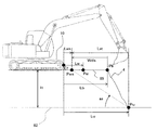
- FIG. 1 is an external view of a hydraulic excavator 1 which is an example of a self-propelled working machine.
- the excavator 1 includes a lower traveling body 10, an upper revolving body 11 that is turnably provided on the lower traveling body 10, a boom 13 that is provided to be rotatable in front of the upper revolving body 11, and a tip of the boom 13.
- An articulated front working device composed of an arm 14 rotatably provided, a bucket 15 rotatably provided at the tip of the arm 14, a boom 13, an arm 14, and the bucket 15.
- an operation chamber 17 in which an operator gets in and operates the excavator 1 an operation lever (operation device) 19 (see FIG. 9) provided in the operation chamber 17 for operating the excavator 1, and an operation lever 19
- the controller 18 is configured to control the operation of the excavator 1 based on the output (hydraulic signal or electric signal).
- the bench includes a bench upper surface (floor) 85 that is a plane on which the excavator 1 is placed during excavation work, and an excavation surface 4 that is a downward inclined surface (bench side surface) connected to the bench upper surface 85.
- an edge 86 appears at the boundary between the bench upper surface 85 and the excavation surface 4.
- the excavator 1 is placed on the upper surface 85 of the bench so that the edge 86 is positioned in front of the excavator, and the front work device 12 is appropriately expanded and contracted from the position to excavate the excavation surface 4.
- a laser distance meter 24 that is a distance sensor that measures the distance to the surrounding object and mainly detects the surface shape of the object to be excavated (bench) is a shovel ground surface 85. Is fixed at a predetermined angle (laser rangefinder mounting angle) ad (see FIG. 11). Inside the operation room 17, a monitor 21, a setting input device 20, and a work position display switch 27 (all of which will be described later) are provided.
- the upper swing body 11 includes a wireless device 26 that is a communication device for communicating with external devices and computers, and a computer (for example, a microcomputer) configured to execute various types of information processing related to the excavator 1.
- a controller (control device) 18 is provided.
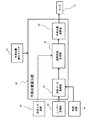
- FIG. 2 is an overview diagram showing a system configuration of a work support system for a work machine that is mounted on the hydraulic excavator 1 and displays a work position.
- the same parts as those in the previous figure may be denoted by the same reference numerals and description thereof may be omitted (the same applies to the subsequent figures).
- the work support system is configured as a program in the setting input device 20 which is an input device (keyboard, mouse, a plurality of buttons, a touch panel, etc.) for changing various settings of the work support system, and the controller 18, and the next excavation is performed.
- a work position calculation unit 30 that calculates a stop position (sometimes referred to as “work position”) of the excavator 1 when performing the operation, and information on the work position Pw (see FIG. 6 described later) or the work position Pw (for example, A monitor (display device) 21 that displays a horizontal distance Lw (see FIG. 6) from the front end Cf (see FIG.
- a work position display switch 27 for selectively switching OFF may be ON / OFF of work position calculation by the work position calculation unit 30).
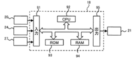
- FIG. 3 shows the hardware configuration of the controller 18.
- the controller 18 includes an input unit 91, a central processing unit (CPU) 92 that is a processor, a read-only memory (ROM) 93 and a random access memory (RAM) 94 that are storage devices, and an output unit 95.
- the input unit 91 inputs information and signals from external devices (for example, the setting input device 20, the laser distance meter 24, and the work position display switch 27), and performs A / D conversion as necessary.
- the ROM 93 is a recording medium in which a program or the like is stored, and the CPU 92 performs predetermined arithmetic processing on signals taken from the input unit 91 and the memories 93 and 94 in accordance with the program stored in the ROM 93.
- the work position calculation unit 30 includes a terrain data acquisition unit 31, an excavation area determination unit 32, and a work position calculation unit 34.
- the terrain data acquisition unit 31 determines the position of the excavation target end Pb (see FIG. 6), which is a point on the edge 86 of the bench upper surface 85, and the excavation reference plane 82. This is a portion for acquiring the height H (see FIG. 6) of the bench upper surface 85 of the above.
- the excavation target end Pb is a reference point for calculating the work position Pw, and may be defined at the boundary between the bench upper surface 85 and the excavation surface 4, and is not necessarily defined on the edge 86 as shown in FIG. None (refer to FIGS. 19 and 20 described later for details).
- the “excavation target end Pb” is defined as a point where a surface passing through the turning center of the shovel 1 and the center of the work device 12 intersects the edge 86 of the bench upper surface 85, and the “reference surface 82” is defined as the shovel.
- 1 is the bench top surface one step below the bench top surface 85 on which 1 is placed or the bottom surface of the bottom bench.
- the excavation area determination unit 32 determines an area (“excavation” in the excavation target where an assumed excavation amount (described later) is obtained from the excavation target by one excavation operation (described later) of the excavator 1 based on the acquisition result of the topography data acquisition unit 31. This may be referred to as “region S”). Although details will be described later, in the present embodiment, the excavation area S is determined based on the height H of the bench upper surface 85 and an area sb (described later) that can be derived from the assumed excavation amount.
- one excavation operation refers to the period from when the tip of the bucket 15 touches the excavation surface 4 to when the height of the tip of the bucket 15 reaches the bench upper surface 85 during excavation of the bench. This is a series of operations.
- the “assumed excavation amount” is set based on the capacity of the bucket 15 (bucket capacity).
- the bucket capacity varies depending on the type of the hydraulic excavator 1.
- Specific examples of the estimated excavation amount include, for example, the capacity when the excavated material is put by scraping at the upper edge of the bucket (flat capacity), or the excavated material is further added to the bucket in a state where the excavated material is flatly stacked.
- the capacity when piled up (mounting capacity) can be used. From the viewpoint of maximizing work efficiency, it is preferable to use the pile capacity as the assumed excavation amount, but the assumed excavation amount is not particularly limited, and any value less than the maximum capacity can be adopted. In the present embodiment, the pile capacity is assumed as the assumed excavation amount.
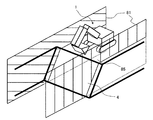
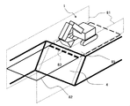
- FIG. 4 is an overview diagram showing an example of work of the hydraulic excavator 1, and shows a state in which the excavator 1 finishes excavation of the excavation surface 4 by one excavation operation and loads the excavated material 5 inside the bucket 15.
- FIG. FIG. 5 is a schematic view showing a state in which the excavator 1 turns after completion of one excavation operation, moves the bucket 15 onto the loading platform of the transporting machine (dump truck) 2, and discharges the excavated material 5.
- the excavator 1 alternately repeats the excavation work and the loading work shown in FIGS. 4 and 5 until the loading platform of the transporting machine 2 is full.
- the excavator 1 moves backward and repeats the excavation work and the loading work again.
- a predetermined excavation amount is to be maintained in each excavation operation, if the excavator 1 and the excavation target end 7 are close to each other, the position of the bucket 15 at the end of one excavation operation is the scaffolding of the excavator 1
- the predetermined excavation amount may not be ensured in order to prevent it from reaching the maximum.
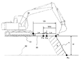
- FIG. 6 is a side sectional view showing the positional relationship between the excavator 1 and the excavation surface 4 (bench sectional view by a plane passing through the turning center of the excavator 1 and the center of the working device 12).
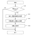
- FIG. 7 is a flowchart showing the processing of the work position calculation unit 30. Next, a procedure for displaying the distance Lw to the work position Pw on the monitor 21 will be described with reference to FIG.
- the work position calculation unit 30 first determines whether the work position display switch 27 is ON in step S100. If the work position display switch 27 is not ON, nothing is displayed on the monitor 21 and the process is terminated.
- the excavation area determination unit 32 acquires the height H and the position of the excavation target end Pb from the landform data acquisition unit 31 in step 101, and proceeds to step 102.
- the excavation area determination unit 32 determines the excavation area S based on the area sb of the excavation area S in the side sectional view of FIG. 6 and the height H acquired by the topography data acquisition unit 31.
- the excavation amount setting distance Ls is calculated.
- the excavation area S passes through two points Pb and Pu related to the excavation surface 4 and is simplified as a parallelogram having a constant area sb.
- the area sb of the excavation region S is determined from the assumed excavation amount, and the position of the top left corner Pa of the parallelogram (in other words, the length of the top and bottom sides of the parallelogram) changes according to the value of the height H. . Therefore, the excavation amount setting distance Ls, which is the length of the top and bottom sides of the parallelogram excavation area S, can be calculated from sb and H by the following equation (1).
- Ls sb / H (1)
- the work position calculation unit 34 calculates a work position distance Lw that is a horizontal distance from the tip Cf of the lower traveling body 10 of the excavator 1 to the work position Pw.
- the work position distance Lw is expressed by the following formula (3) using a distance Lb from the tip Cf of the lower traveling body 10 of the excavator 1 to the excavation target end Pb (sometimes referred to as “excavation target end distance”).
- the distance Lb is acquired by the terrain data acquisition unit 31 via the laser distance meter 24 or the wireless device 26.
- Lw Lb ⁇ Wd Formula (3)
- the longitudinal excavation width Wd is not limited to the above-described calculation method, and may be configured to be set based on a different calculation formula by the setting input device 20.
- the work position calculation unit 30 finally outputs the distance Lw to the monitor 21 in step 103 and ends the process.
- FIG. 8 is a view showing one display example of the distance Lw to the work position Pw on the monitor 21 provided in the operation room 17. A method of displaying the work position Pw will be described with reference to FIG.
- monitor 8 is provided with a monitor upper part 22 and a monitor lower part 23 as display areas.
- the work position distance Lw from the tip of the lower traveling body 10 to the work position is displayed as a numerical value based on the output of the work position calculation unit 30 described in FIG.
- a numerical value ( ⁇ 0.5 m) displayed on the right side of the character string “to the front end” in the example of FIG. 8 indicates the distance Lw to the work position Pw.
- the distance Lw is a negative value.
- the fact that the distance Lw is negative as in the example of FIG. 8 indicates that the tip Cf of the lower traveling body 10 has exceeded the work position Pw and the excavator 1 should be moved backward.
- the distance Lw is positive, it indicates that the tip Cf of the lower traveling body 10 has not reached the work position Pw and the hydraulic excavator 1 should be advanced.
- the distance Lw is negative, it is preferable to alert the operator by displaying a warning image 42 on the screen as shown in FIG. Instead of the warning image 42, a warning message may be displayed.
- a sound output device that outputs a warning sound or a warning sound instead of the warning image 42 may be additionally installed.
- an image of a side sectional view of the excavator 1 similar to that in FIG. 6 (surface shape image to be excavated) is displayed.
- the work position display line 84 indicating the work position Pw, the excavation area S, and the image of the hydraulic excavator 1 are superimposed on the image of the side sectional view. It is displayed.
- the image of the side sectional view is created by the controller 18 based on the surface shape of the excavation target detected by the laser distance meter 24. It is preferable that the image position of the hydraulic excavator and the posture of the image of the work device on the lower monitor 23 are configured to be linked to the position and posture of the actual machine.
- the positional relationship between the two can be easily grasped. Further, when the excavation area S is displayed, the target trajectory of the tip of the bucket 15 at the next excavation operation can be grasped, which contributes to maximization of excavation capacity and high work efficiency maintenance.
- the work support system for work machines has the bench height H and the assumption that the cross-sectional area sb of the area excavated in each of the excavation operations is held constant.
- the excavation area S is determined based on the excavation amount, and the position of the excavator 1 suitable for excavation in the next excavation operation is calculated as the work position Pw based on the excavation area S.
- the distance Lw from the foremost end Cf of the lower traveling body 10 of the excavator 1 to the work position Pw is calculated and displayed on the monitor 21.
- the shape of the excavation region S is not limited to the parallelogram shown in FIG. 6, and may be configured to be changeable to another shape by the setting input device 20.
- the excavation amount setting distance Ls is calculated by an expression other than the above expression (1), but if the shape of the excavation area S is determined in advance, the area sb (assumed excavation amount) and the shape of the excavation target To Ls can be calculated.
- a part of the excavator ground contact surface 85 is set as an upper base
- a part of the reference surface 82 is a lower base
- a trapezoid having a perpendicular to the excavator ground contact surface 85 and the excavation surface 4 as a leg is set as the excavation region S. May be.
- a model of the movement trajectory of the tip of the bucket 15 when excavating the region where the cross-sectional area is sb by one excavation operation is stored for each height H, and the model and height of the movement trajectory are stored.
- You may comprise so that the shape of the excavation area
- region S may be selected suitably based on H.
- the excavation operation starts by applying the tip of the bucket 15 to the point Pu located at the lower end of the excavation surface 4.
- the bench height H is high and the point Pu is outside the movable range of the bucket 15.
- the excavation area S is set such that the intersection of the maximum movable range of the bucket 15 and the excavation surface 4 is the starting point of the excavation operation. That is, the present embodiment is applicable even when the tip of the bucket 15 does not reach the point Pu.
- the excavation area S In calculating the estimation and the work position Pw, the surface shape may be used as the shape of the excavation surface 4. In this case, since the estimation accuracy of the excavation area S is improved, the accuracy of the work position Pw is also improved. Moreover, the precision of the side sectional view displayed on the monitor lower part 23 can be improved.
- the apparatus for acquiring the shape of the excavation target is not limited to the laser distance meter 24, and may be another configuration capable of acquiring the shape of the excavation target.
- a distance measuring camera or an ultrasonic sensor can be substituted.
- the work position may be set using the terrain data acquired from an external computer via the wireless device 26.
- the height H may be set based on the work plan acquired from the site manager, and the height H is measured from below the excavation target by the transport machine 2. You may comprise so that it may transmit to the hydraulic excavator 1.
- the shape of the excavation surface 4 at the next excavation may be estimated from the tip locus of the excavator 1.
- the margin distance Lm is not necessarily set, and may be set to zero.
- the margin distance Lm is zero, the distance between the excavation target end Pb and the work position Pw coincides with the excavation amount setting distance Ls and becomes the minimum.
- the display on the monitor 21 is not limited to the above-described content.
- a top view of the excavation object including the excavation surface 4 and the ground contact surface 85 and the hydraulic excavator 1 is displayed on the monitor lower portion 23, and the work position Pw is displayed there. , Pws may be superimposed and displayed.
- FIG. 9 is an overview diagram showing another configuration of the work support system for the work machine that is mounted on the hydraulic excavator 1 and displays the work position.
- the work position calculation unit 30 in this figure includes a stable region setting unit 33, a travel determination unit 35, and a display update unit 36 in addition to the configuration of the work position calculation unit 30 shown in FIG.
- the terrain data acquisition unit 31 acquires the shape of the digging target based on the distance information output from the laser rangefinder 24 or the terrain data provided by the wireless device 26, and further, the height H of the digging target and the digging target end Pb. This is a part for acquiring the position and the shape of the excavation surface 4.
- the stable region setting unit 33 is based on the surface shape of the excavation target and the stability angle as (see FIG. 10), and is an area in which the excavator 1 can stably perform excavation work on the upper surface of the excavation target (“stable region”). It is a part for calculating.
- the work position calculation unit 34 is a part that calculates the work position (Pw or Pws) of the excavator 1.
- the travel determination unit 35 is a part that determines whether or not a travel instruction has been given to the excavator 1 based on the output of the operation lever (operation device) 19.
- the display update unit 36 is output from the work position calculation unit 34 based on the determination of the travel determination unit 35 and is displayed on the monitor 21 and information about the work position (Pw or Pws) and the excavation area (for example, up to the work position Pw). The distance Lw and the distance Lws to the work position Pws) are updated.
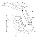
- FIG. 10 is a side sectional view showing the positional relationship between the excavator 1 and the excavation surface 4 in the second embodiment. A method for calculating the second work position Pws determined based on the stable region will be described with reference to FIG.
- the second excavation target end Pu located on the lower edge of the excavation surface 4 is acquired by the terrain data acquisition unit 31.
- the terrain data acquisition unit 31 acquires the surface shape of the excavation surface 4 including the second excavation target end Pu will be described with reference to FIG.
- the terrain data acquisition unit 31 outputs the output of the laser rangefinder 24 (the point group relative horizontal distance Ln and the point group relative vertical distance) based on the mounting position information (length Ld, height Hd, and angle ad) of the laser rangefinder 24.
- Hn) is converted into a point county horizontal distance Ln ′ and a point county vertical distance Hn ′ with respect to the tip Cf of the lower traveling body 10.
- Ln ′ and Hn ′ are converted by the following equation (7) using a rotation matrix.
- Ln ′ Ln ⁇ cos (ad) ⁇ Hn ⁇ sin (ad) ⁇ Ld
- Hn ′ Ln ⁇ sin (ad) + Hn ⁇ cos (ad) ⁇ Hd (7)
- the surface shape of the excavation target with respect to the tip Cf of the lower traveling body 10 is acquired by performing the same calculation for all the points included in the point cloud.
- the shape of the excavation surface 4 is described as a two-dimensional shape in the side section, but may be converted into a three-dimensional shape to be excavated by using a three-dimensional rotation matrix. .
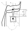
- FIG. 12 is a side sectional view showing a method for acquiring the positions of the excavation target ends Pb and Pu based on the toe trajectory of the bucket 15 in excavation work.
- the controller 18 monitors the output of the pressure sensor 29, and starts excavation when the load on the arm cylinder 16 increases and exceeds a predetermined value. And the toe position of the bucket 15 at that time is set as the second excavation target end Pu. Subsequently, the controller 18 monitors the toe position of the bucket 15 after the start of excavation, and determines that excavation is completed when the height of the toe of the bucket 15 is higher than the height of the excavator ground contact surface 85. The toe position is set as the excavation target end Pb.
- the stable angle (rest angle) as is the maximum inclination angle of the excavation surface 4 that is stable without causing the excavation surface 4 of the bench to collapse spontaneously, and is set to the second excavation target end Pu.
- the value of the stability angle as varies depending on the soil quality of the bench, and is stored in advance in a storage device in the controller 18 via the setting input device 20 or the like.
- the stable region setting unit 33 sets the horizontal angle Lst (sometimes referred to as “excavation target stable distance”) from the second excavation target end Pu to the position Pws at which the excavation target becomes stable as the stable angle as and the height H.
- Lst H / tan (as) (4)
- the work position calculation unit 34 calculates a horizontal distance Lws from the tip Cf of the lower traveling body 10 to the second work position Pws (sometimes referred to as “second work position distance”).
- the second work position distance Lws is expressed by the following formula (5) using the horizontal distance Lu from the tip Cf of the lower traveling body 10 to the second excavation target end Pu.
- the horizontal distance Lu is acquired by the terrain data acquisition unit 31 via the laser distance meter 24 or the wireless device 26.
- Lws Lu ⁇ Lst (5)
- the horizontal distance Wds from the excavation target end Pb to the second work position Pws (sometimes referred to as “second longitudinal excavation width”) is determined from the tip Cf of the lower traveling body 10 of the excavator 1 to the excavation target.
- Lb to the end Pb (sometimes referred to as “excavation target end distance”)
- the work position calculation unit 34 compares the second front / rear direction excavation width Wds and the front / rear direction excavation width Wd, and sets the larger one as the work position. For example, when the second front-rear direction excavation width is large, the position Pws using the second front-rear direction excavation width Wds is set as the work position.
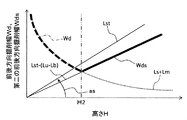
- FIG. 13 is a graph showing values of the longitudinal excavation width Wd and the second longitudinal excavation width Wds with respect to the height H. A change in the longitudinal excavation width Wd and the second longitudinal excavation width Wds calculated based on the above-described method based on the height H will be described with reference to FIG.
- the smaller the height H the greater the work position distance Ls necessary to secure the predetermined area sb. Therefore, the longitudinal excavation width Wd is also increased at the same time, and the work position Pw extends from the excavation target end Pb. Leave.
- the excavation amount setting distance Ls necessary for securing the predetermined area sb is smaller and the longitudinal excavation width Wd is also smaller, so that the work position Pw is closer to the excavation target end Pb. .
- the work position calculation unit 34 compares the above-described longitudinal excavation width Wd and the second longitudinal excavation width Wds and sets the larger value as the work position. As shown in FIG. 13, (A) in the region where the height H is smaller than H2, the front and rear direction excavation width Wd is large, so the work position Pw using the front and rear direction excavation width Wd is output. (B) When the height H is H2, the front / rear direction excavation width Wd and the second front / rear direction excavation width Wds match, and therefore, the work position Pw using the front / rear direction excavation width Wd is output for convenience (second). May be output). (C) Since the second longitudinal excavation width Wds is large in the region where the height H is larger than H2, the second work position Pws using the second longitudinal excavation width Wds is output.
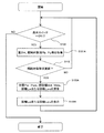
- FIG. 14 is a flowchart showing processing of the work position calculation unit 30 according to the second embodiment. A method for displaying the work position will be described with reference to FIG. The same processes as those in the flowchart of the previous figure (FIG. 7) may be given the same numbers and the description thereof may be omitted (the same applies to the subsequent flowcharts).
- step 102A the excavation area determination unit 32 estimates the excavation area S by the method described above. Then, the work position calculation unit 34 calculates the excavation amount setting distance Ls by using the area sb and the height H and the above equation (1), and adds the margin Lm to this to calculate the longitudinal excavation width Wd. (Formula (2) above).
- the stable region setting unit 33 calculates the excavation target stable distance Lst using the above equation (4). Then, the work position calculation unit 34 calculates the second work position distance Lws using the above formula (5), and calculates the second longitudinal digging width Wds using the above formula (6).
- step 103A the display update unit 36 outputs the distance (Lw or Lws) to the monitor 21 and ends the process.
- the display form of the distance (Lw or Lws) to the monitor 21 is the same as that shown in FIG.
- the work support system for a work machine is derived based on the longitudinal excavation width Wd derived based on the excavation region S and the stable angle as of the excavation target.
- the size of the excavation width Wd in the front-rear direction is compared, and the distance (Lw or Lws) to the work position (Pw or Pws) according to the larger one is displayed on the monitor 21. If comprised in this way, since the hydraulic shovel 1 is always arrange
- FIG. 15 is a flowchart showing the processing of the work position calculation unit 30 according to the third embodiment.
- step 112 the terrain data acquisition unit 31 determines whether or not the surface shape of the excavation target has changed based on the terrain data acquired in step 101A. If the surface shape of the excavation target has not changed, the process returns to step S100.
- the process proceeds to step 102A and step 103A, and the display update unit 36 displays the distance Lw or the distance Lws on the monitor 21 and updates the display screen. After updating the display screen of the monitor 21, the process returns to step S100, and the above-described processes are repeated.
- the distance (Lw or Lws) to the work position in the next excavation operation is determined.
- the monitor display was updated.
- FIG. 16 is a flowchart showing processing of the work position calculation unit 30 according to the fourth embodiment.
- step 122 the traveling determination unit 35 determines whether or not there has been an input of a lever (traveling lever) that instructs traveling via the operation lever 19. If there is no input of the travel lever (instruction for advance / retreat by the lower traveling body 10), the display on the monitor 21 of the distance (Lw or Lws) to the work position in the next excavation operation is maintained. Return to. When there is an input from the travel lever, the process proceeds to step 102A and step 103A, and the display update unit 36 displays the distance Lw or the distance Lws on the monitor 21 and updates the display screen. After updating the display screen of the monitor 21, the process returns to step S100, and the above-described processes are repeated.
- a lever traveling lever
- the monitor display of the distance (Lw or Lws) to the work position in the next excavation operation is continuously updated. did. If the system is configured in this way, the distance to the work position is automatically updated as the hydraulic excavator 1 is moved by the travel lever, so that work efficiency can be improved.
- the distance is updated based on the presence or absence of lever input of the operation lever 19.
- the distance is updated by detecting the operation of the lower traveling body 10 that is the traveling device of the excavator 1.
- a configuration may be adopted.
- a configuration in which the distance is updated by detecting the operation of the drive source (hydraulic motor or electric motor) of the lower traveling body 10 may be employed.
- the position of the transport machine (dump truck) may be monitored and updated at the timing when the start of movement of the transport machine is detected.
- the operation that triggers the display update is not limited to running, and other operations may be used as a reference.
- the excavator operation may be classified into excavation, turning, and loading, and the work position may be updated after detecting the loading operation.
- the third embodiment and the fourth embodiment described above can be combined. That is, when at least one of the surface shape of the excavation object is changed, when the traveling lever is input, and when the lower traveling body 10 is operated (when the hydraulic excavator 1 is operated), The distance to the work position in the next excavation operation may be calculated again, and the calculation result may be displayed on the monitor 21.
- FIG. 17 is a bird's-eye view showing a working range for the excavator 1 and the excavation surface 4.
- FIG. 18 is an overhead view showing an excavation target end reference line 83 generated by the intersection of the reference plane 82 and the excavation plane 4 when a reference plane (reference elevation plane) 82 is set with respect to the excavator ground contact plane 85 of the hydraulic excavator 1.
- FIG. 19 is a top view showing the relationship between the excavator 1, the excavation target end reference line 83 and the excavation target end Pb shown in FIG.
- the excavation target end Pb can be set even in the case of a smooth transition.
- the distance Lw ′ may be displayed on the monitor 21 instead of the distance Lw.
- the distance Lw ′ is a work position distance in the front direction of the excavator 1 between the work position Pw and the tip Cf of the lower traveling body 10.
- the excavation target end Pb is not limited to the configuration in which the horizontal direction of the excavation target end reference line 83 is minimized.
- the position where the average or maximum horizontal distance described above is taken is the excavation target end. You may make it the structure set as Pb.
- the setting input device 20 may be configured so that the above methods can be applied in appropriate combination.
- the second excavation target end Pu may be configured to set a reference plane different from the reference plane 82 and determine the same as the excavation target end Pb using the different reference plane.
- the work position calculation unit 30 is not limited to the operation performed by the controller attached to the hydraulic excavator 1, but the name processing necessary for calculating and displaying the stop position of the hydraulic excavator 1 is performed by an external computer, and the result is obtained by the hydraulic pressure. You may comprise so that it may transmit to the shovel 1 via the radio
- the setting input device 20 is not limited to being installed in the operation room 17, and is configured by a portable information terminal that can be carried by a supervisor at the work site and the like. You may comprise so that information may be transmitted.
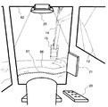
- FIG. 21 is an overhead view of the front of the excavator 1 from the inside of the operation chamber 17. With reference to FIG. 21, another method for guiding the excavator 1 to the work positions Pw and Pws will be described.
- a head-up display 25 that has a built-in computer that performs control processing related to video display and displays a virtual video on the windshield 62 in front of the operation room 17 is attached to the upper part of the operation room 17.
- the terrain data acquisition unit 31 outputs the shape of the edge 86 of the excavator ground contact surface 85 to the head-up display 25.
- the head-up display 25 has a target end shape 87 obtained by offsetting the shape of the edge 86 output from the terrain data acquisition unit 31 by the working position distance Lw (or Lws) toward the shovel side on the windshield 62 in front of the operation chamber 17. indicate.
- the operator moves and stops the excavator 1 so that the target end shape 87 and the edge 86 of the excavation surface 4 coincide with each other while viewing the front image. Thereby, the shovel 1 can be stopped at the work positions Pw and Pws.
- the guidance display device for guiding the excavator 1 to the work positions Pw, Pws is not limited to the monitor 21 or the head-up display 25, but a head-mounted display or windshield glass worn by the operator is replaced with a monitor. It is possible to use other display devices such as a device that synthesizes and displays video from an external camera and work position information.
- the components related to the controller 18 and the functions and execution processes of the components may be realized by hardware (for example, logic for executing each function is designed by an integrated circuit). good. Further, distributed processing may be performed by a plurality of computers having the same or different installation locations. Further, the configuration related to the controller 18 may be a program (software) that realizes each function related to the configuration of the controller 18 by being read and executed by an arithmetic processing device (for example, a CPU). Information related to the program can be stored in, for example, a semiconductor memory (flash memory, SSD, etc.), a magnetic storage device (hard disk drive, etc.), a recording medium (magnetic disk, optical disc, etc.), and the like.
- SYMBOLS 1 Hydraulic excavator, 10 ... Undercarriage, 12 ... Front working device, 17 ... Operation room, 18 ... Controller (control device), 19 ... Operation lever (operation device), 21 ... Monitor (display device), 24 ... Laser Distance meter (shape detection device), 30 ... work position calculation unit, 31 ... terrain data acquisition unit, 32 ... excavation area determination unit, 34 ... work position calculation unit, 35 ... travel determination unit, 36 ... display update unit, 82 ... Reference plane, 83 ... excavation target end reference line, 85 ... bench upper surface (upper surface), H ... height from reference plane 82, as ... stability angle, S ... excavation area, Pb ... excavation target end (reference point), Pw , Pws ... work position, Lw, Lws ... work position distance
Abstract
Description
図1及び図2を用いて、作業機械、および作業機械に備えられる作業支援システムの構成について説明する。 <First Embodiment>
The configuration of the work machine and the work support system provided in the work machine will be described with reference to FIGS. 1 and 2.
Ls=sb/H…式(1) In step 102, first, the excavation
Ls = sb / H (1)
Wd=Ls+Lm…式(2) Next, the work
Wd = Ls + Lm Expression (2)
Lw=Lb-Wd…式(3) Further, the work
Lw = Lb−Wd Formula (3)
図9は油圧ショベル1に搭載され、作業位置を表示する作業機械の作業支援システムの他の構成を示す概観図である。この図の作業位置算出部30は、図2に示した作業位置算出部30が備える構成に加えて、安定領域設定部33と、走行判定部35と、表示更新部36を備えている。 Second Embodiment
FIG. 9 is an overview diagram showing another configuration of the work support system for the work machine that is mounted on the
Ln’=Ln×cos(ad)-Hn×sin(ad)-Ld
Hn’=Ln×sin(ad)+Hn×cos(ad)-Hd ・・・(7) FIG. 11 is a side sectional view showing a positional relationship among the
Ln ′ = Ln × cos (ad) −Hn × sin (ad) −Ld
Hn ′ = Ln × sin (ad) + Hn × cos (ad) −Hd (7)
Lst=H/tan(as)…式(4) Returning to FIG. 10, the stable angle (rest angle) as is the maximum inclination angle of the
Lst = H / tan (as) (4)
Lws=Lu-Lst…式(5) Subsequently, the work
Lws = Lu−Lst (5)
Wds=Lb-Lws…式(6) At this time, the horizontal distance Wds from the excavation target end Pb to the second work position Pws (sometimes referred to as “second longitudinal excavation width”) is determined from the tip Cf of the lower traveling
Wds = Lb−Lws Expression (6)
本実施形態に係る作業機械の作業支援システムの構成は図9と同じとする。図15は第3実施形態に係る作業位置算出部30の処理を示すフローチャートである。 <Third Embodiment>
The construction of the work machine work support system according to this embodiment is the same as that shown in FIG. FIG. 15 is a flowchart showing the processing of the work
本実施形態に係る作業機械の作業支援システムの構成も図9と同じとする。図16は第4実施形態に係る作業位置算出部30の処理を示すフローチャートである。 <Fourth embodiment>
The configuration of the work machine work support system according to the present embodiment is the same as that shown in FIG. FIG. 16 is a flowchart showing processing of the work
Claims (5)
- 自走可能な作業機械の作業支援システムにおいて、
前記作業機械の1回の掘削動作による想定掘削量に基づいて、前記作業機械の1回の掘削動作により掘削対象から前記想定掘削量が得られる領域を掘削領域として決定し、当該掘削領域に基づいて次回の掘削動作を行う際の前記作業機械の作業位置を算出するように構成された制御装置と、
前記作業位置に関する情報を表示する表示装置とを備えることを特徴とする作業機械の作業支援システム。 In the work support system for self-propelled work machines,
Based on the assumed excavation amount by one excavation operation of the work machine, an area in which the estimated excavation amount is obtained from the excavation target by one excavation operation of the work machine is determined as an excavation region, and based on the excavation region A control device configured to calculate a work position of the work machine when performing a next excavation operation;
A work support system for a work machine, comprising: a display device that displays information on the work position. - 請求項1に記載の作業機械の作業支援システムにおいて、
前記掘削対象は、前記作業機械が掘削作業時に載る上面と、当該上面に接続する下り傾斜面である掘削面とを有し、
前記制御装置は、前記上面の基準面からの高さと前記想定掘削量に基づいて前記掘削領域を決定し、前記上面と前記掘削面の境界部に定義された基準点から前記作業位置までの距離を前記掘削領域に基づいて算出し、前記距離に基づいて前記作業位置を算出するように構成されていることを特徴とする作業機械の作業支援システム。 The work machine work support system according to claim 1,
The excavation target has an upper surface on which the work machine is placed during excavation work, and an excavation surface that is a downward inclined surface connected to the upper surface,
The control device determines the excavation area based on the height of the upper surface from the reference surface and the assumed excavation amount, and the distance from the reference point defined at the boundary between the upper surface and the excavation surface to the work position Is calculated based on the excavation area, and the work position is calculated based on the distance. - 請求項2に記載の作業機械の作業支援システムにおいて、
前記掘削対象の表面形状を検出する形状検出装置をさらに備え、
前記制御装置は、前記形状検出装置により検出された前記表面形状に基づいて前記掘削対象の表面形状画像を作成するように構成されており、
前記表示装置は、さらに、前記表面形状画像上に前記掘削領域を表示することを特徴とする作業機械の作業支援システム。 The work machine work support system according to claim 2,
Further comprising a shape detection device for detecting the surface shape of the excavation target;
The control device is configured to create a surface shape image of the excavation target based on the surface shape detected by the shape detection device,
The display device further displays the excavation area on the surface shape image. - 請求項3に記載の作業機械の作業支援システムにおいて、
前記制御装置は、前記作業機械が動作したとき、前記作業機械の操作装置に入力があったとき、及び、前記表面形状が変化したときの少なくとも1つが確認されたとき、前記作業機械の作業位置を改めて算出するように構成されており、
前記表示装置は、前記改めて算出された作業位置に関する情報を表示することを特徴とする作業機械の作業支援システム。 The work machine work support system according to claim 3,
The control device is configured such that when at least one of the operation of the work machine, the input to the operation device of the work machine, and the change of the surface shape is confirmed, the work position of the work machine Is calculated again,
The work support system for a work machine, wherein the display device displays information on the work position calculated anew. - 請求項4に記載の作業機械の作業支援システムにおいて、
前記制御装置は、前記掘削対象の安定角に基づいて前記上面の上に前記作業機械の他の作業位置をさらに算出し、
前記表示装置は、前記作業位置と前記他の作業位置のうち前記基準点からの距離が大きいほうに関する情報を表示することを特徴とする作業機械の作業支援システム。 The work machine work support system according to claim 4,
The control device further calculates another work position of the work machine on the upper surface based on the stability angle of the excavation target,
The work support system for a work machine, characterized in that the display device displays information on the work position and the other work position that have a larger distance from the reference point.
Priority Applications (6)
| Application Number | Priority Date | Filing Date | Title |
|---|---|---|---|
| CN201680038340.0A CN107709673B (en) | 2015-06-29 | 2016-06-27 | Work support system for work machine |
| AU2016288150A AU2016288150B2 (en) | 2015-06-29 | 2016-06-27 | Work assist system for work machines |
| KR1020177037637A KR102025124B1 (en) | 2015-06-29 | 2016-06-27 | Job support system of working machine |
| CA2989984A CA2989984C (en) | 2015-06-29 | 2016-06-27 | Work assist system for work machine |
| EP16817857.2A EP3315671A4 (en) | 2015-06-29 | 2016-06-27 | Work assist system for work machines |
| US15/737,859 US11008732B2 (en) | 2015-06-29 | 2016-06-27 | Work assist system for work machine |
Applications Claiming Priority (2)
| Application Number | Priority Date | Filing Date | Title |
|---|---|---|---|
| JP2015129815A JP6522441B2 (en) | 2015-06-29 | 2015-06-29 | Work support system for work machine |
| JP2015-129815 | 2015-06-29 |
Publications (1)
| Publication Number | Publication Date |
|---|---|
| WO2017002749A1 true WO2017002749A1 (en) | 2017-01-05 |
Family
ID=57608629
Family Applications (1)
| Application Number | Title | Priority Date | Filing Date |
|---|---|---|---|
| PCT/JP2016/068975 WO2017002749A1 (en) | 2015-06-29 | 2016-06-27 | Work assist system for work machines |
Country Status (8)
| Country | Link |
|---|---|
| US (1) | US11008732B2 (en) |
| EP (1) | EP3315671A4 (en) |
| JP (1) | JP6522441B2 (en) |
| KR (1) | KR102025124B1 (en) |
| CN (1) | CN107709673B (en) |
| AU (1) | AU2016288150B2 (en) |
| CA (1) | CA2989984C (en) |
| WO (1) | WO2017002749A1 (en) |
Cited By (3)
| Publication number | Priority date | Publication date | Assignee | Title |
|---|---|---|---|---|
| CN111771032A (en) * | 2018-03-30 | 2020-10-13 | 株式会社小松制作所 | Control device for working machine, control device for excavating machine, and control method for working machine |
| EP3779067A4 (en) * | 2018-03-27 | 2021-04-07 | Sumitomo Heavy Industries, Ltd. | Excavator |
| US11851854B2 (en) | 2017-09-06 | 2023-12-26 | Hitachi Construction Machinery Co., Ltd. | Work machine |
Families Citing this family (21)
| Publication number | Priority date | Publication date | Assignee | Title |
|---|---|---|---|---|
| JP6480830B2 (en) * | 2015-08-24 | 2019-03-13 | 株式会社小松製作所 | Wheel loader control system, control method therefor, and wheel loader control method |
| CN108603360B (en) * | 2016-03-31 | 2022-10-21 | 住友重机械工业株式会社 | Excavator |
| EP3584120B1 (en) * | 2017-02-17 | 2021-04-14 | Sumitomo Heavy Industries, Ltd. | Work machine surroundings monitoring system |
| JP6963007B2 (en) * | 2017-03-31 | 2021-11-05 | 住友建機株式会社 | Excavator, excavator display device and image display method on excavator |
| CN110998032A (en) * | 2017-07-31 | 2020-04-10 | 住友重机械工业株式会社 | Excavator |
| CN109757114B (en) * | 2017-09-08 | 2021-09-28 | 株式会社小松制作所 | Display control device for working machine, and display control method for working machine |
| JP6841784B2 (en) | 2018-03-28 | 2021-03-10 | 日立建機株式会社 | Work machine |
| AU2018416541B2 (en) * | 2018-03-29 | 2021-06-17 | Komatsu Ltd. | Control system and method for work machine, and work machine |
| JP7014007B2 (en) * | 2018-03-29 | 2022-02-01 | コベルコ建機株式会社 | Remote control system for work machines |
| CN112041510A (en) * | 2018-06-19 | 2020-12-04 | 住友建机株式会社 | Excavator and information processing device |
| JP7188941B2 (en) * | 2018-08-31 | 2022-12-13 | 株式会社小松製作所 | Work machine control device and control method |
| JP7088792B2 (en) | 2018-09-12 | 2022-06-21 | 株式会社小松製作所 | Work machines, controls, and control methods |
| EP3670761B1 (en) | 2018-12-21 | 2021-10-20 | Hiab AB | A vehicle provided with a control system, and a method for the vehicle |
| JP7318414B2 (en) * | 2019-08-21 | 2023-08-01 | コベルコ建機株式会社 | working machine |
| CN114096716B (en) * | 2020-03-25 | 2023-12-05 | 日立建机株式会社 | Driving support system for work machine |
| IT202000016444A1 (en) * | 2020-07-07 | 2022-01-07 | Cnh Ind Italia Spa | ASSISTANT SYSTEM FOR ADJUSTING AN ORIENTATION OF A TOOL AND WORK VEHICLE INCLUDING THE SYSTEM |
| CN116234960A (en) * | 2020-10-02 | 2023-06-06 | 神钢建机株式会社 | Excavation position determination system, excavation control system, and construction machine |
| EP4267807A1 (en) * | 2020-12-28 | 2023-11-01 | Volvo Autonomous Solutions AB | Method and device for controlling excavator |
| DE112022001534T5 (en) * | 2021-03-16 | 2024-02-15 | Sumitomo Heavy Industries, Ltd. | SUPPORT SYSTEM, INFORMATION PROCESSING APPARATUS AND PROGRAM |
| WO2023090070A1 (en) * | 2021-11-19 | 2023-05-25 | 日本精機株式会社 | Work support system, control method for work support system, and control program for work support system |
| JP7342294B1 (en) * | 2023-03-23 | 2023-09-11 | オリエンタル白石株式会社 | Caisson point cloud extraction system and program |
Citations (6)
| Publication number | Priority date | Publication date | Assignee | Title |
|---|---|---|---|---|
| JPH10212740A (en) * | 1997-01-30 | 1998-08-11 | Komatsu Ltd | Automatic excavating method for hydraulic shovel |
| JP2000291076A (en) * | 1999-04-01 | 2000-10-17 | Tokai Rika Co Ltd | Power shovel |
| JP2005068764A (en) * | 2003-08-22 | 2005-03-17 | Shigeno:Kk | Cut and cover tunneling method for installing sewer and cut and cover device for installing sewer |
| JP2011043002A (en) * | 2009-08-24 | 2011-03-03 | Naomasa Nitta | Excavation support device |
| JP2012172428A (en) * | 2011-02-22 | 2012-09-10 | Komatsu Ltd | Position guidance system of hydraulic shovel and control method for position guidance system |
| US20130034419A1 (en) * | 2010-04-20 | 2013-02-07 | Koichiro Tsukane | Construction machine |
Family Cites Families (9)
| Publication number | Priority date | Publication date | Assignee | Title |
|---|---|---|---|---|
| JPS522667B2 (en) | 1973-05-22 | 1977-01-22 | ||
| JPS522667A (en) | 1975-06-24 | 1977-01-10 | Chiyaseizanen Yuugen | Gauze teabag with string |
| KR100353566B1 (en) * | 1997-02-13 | 2003-01-06 | 히다치 겡키 가부시키 가이샤 | A slope excavation control device of a hydraulic excavator, a target slope setting device, and a slope excavation forming method |
| US6108949A (en) * | 1997-12-19 | 2000-08-29 | Carnegie Mellon University | Method and apparatus for determining an excavation strategy |
| CH705152B1 (en) * | 2010-02-23 | 2017-05-15 | Israel Aerospace Ind Ltd | System and method for the autonomous operation of a multitasking earthmoving machine. |
| JP5597222B2 (en) * | 2012-04-11 | 2014-10-01 | 株式会社小松製作所 | Excavator drilling control system |
| US8965642B2 (en) * | 2012-10-05 | 2015-02-24 | Komatsu Ltd. | Display system of excavating machine and excavating machine |
| US8924094B2 (en) * | 2012-10-17 | 2014-12-30 | Caterpillar Inc. | System for work cycle detection |
| US9428885B2 (en) * | 2014-09-15 | 2016-08-30 | Trimble Navigation Limited | Guidance system for earthmoving machinery |
-
2015
- 2015-06-29 JP JP2015129815A patent/JP6522441B2/en active Active
-
2016
- 2016-06-27 CA CA2989984A patent/CA2989984C/en active Active
- 2016-06-27 EP EP16817857.2A patent/EP3315671A4/en active Pending
- 2016-06-27 AU AU2016288150A patent/AU2016288150B2/en active Active
- 2016-06-27 US US15/737,859 patent/US11008732B2/en active Active
- 2016-06-27 KR KR1020177037637A patent/KR102025124B1/en active IP Right Grant
- 2016-06-27 CN CN201680038340.0A patent/CN107709673B/en active Active
- 2016-06-27 WO PCT/JP2016/068975 patent/WO2017002749A1/en active Application Filing
Patent Citations (6)
| Publication number | Priority date | Publication date | Assignee | Title |
|---|---|---|---|---|
| JPH10212740A (en) * | 1997-01-30 | 1998-08-11 | Komatsu Ltd | Automatic excavating method for hydraulic shovel |
| JP2000291076A (en) * | 1999-04-01 | 2000-10-17 | Tokai Rika Co Ltd | Power shovel |
| JP2005068764A (en) * | 2003-08-22 | 2005-03-17 | Shigeno:Kk | Cut and cover tunneling method for installing sewer and cut and cover device for installing sewer |
| JP2011043002A (en) * | 2009-08-24 | 2011-03-03 | Naomasa Nitta | Excavation support device |
| US20130034419A1 (en) * | 2010-04-20 | 2013-02-07 | Koichiro Tsukane | Construction machine |
| JP2012172428A (en) * | 2011-02-22 | 2012-09-10 | Komatsu Ltd | Position guidance system of hydraulic shovel and control method for position guidance system |
Non-Patent Citations (1)
| Title |
|---|
| See also references of EP3315671A4 * |
Cited By (6)
| Publication number | Priority date | Publication date | Assignee | Title |
|---|---|---|---|---|
| US11851854B2 (en) | 2017-09-06 | 2023-12-26 | Hitachi Construction Machinery Co., Ltd. | Work machine |
| EP3779067A4 (en) * | 2018-03-27 | 2021-04-07 | Sumitomo Heavy Industries, Ltd. | Excavator |
| US11959254B2 (en) | 2018-03-27 | 2024-04-16 | Sumitomo Heavy Industries, Ltd. | Shovel |
| CN111771032A (en) * | 2018-03-30 | 2020-10-13 | 株式会社小松制作所 | Control device for working machine, control device for excavating machine, and control method for working machine |
| EP3744909A4 (en) * | 2018-03-30 | 2021-11-10 | Komatsu Ltd. | Control device of working machine, control device of excavating machine, and control method of working machine |
| US11959255B2 (en) | 2018-03-30 | 2024-04-16 | Komatsu Ltd. | Work machine control device, excavating machine control device, and work machine control method |
Also Published As
| Publication number | Publication date |
|---|---|
| KR20180014767A (en) | 2018-02-09 |
| AU2016288150B2 (en) | 2019-12-05 |
| US20190003152A1 (en) | 2019-01-03 |
| CN107709673A (en) | 2018-02-16 |
| CA2989984C (en) | 2020-11-03 |
| AU2016288150A1 (en) | 2018-01-18 |
| CN107709673B (en) | 2020-02-21 |
| JP2017014726A (en) | 2017-01-19 |
| EP3315671A4 (en) | 2019-01-30 |
| EP3315671A1 (en) | 2018-05-02 |
| KR102025124B1 (en) | 2019-09-25 |
| US11008732B2 (en) | 2021-05-18 |
| JP6522441B2 (en) | 2019-05-29 |
| CA2989984A1 (en) | 2017-01-05 |
Similar Documents
| Publication | Publication Date | Title |
|---|---|---|
| WO2017002749A1 (en) | Work assist system for work machines | |
| CN108713084B (en) | Construction machine | |
| JP7408761B2 (en) | Work machine control device and control method | |
| JP6259170B2 (en) | Work machine control device and work machine | |
| JPWO2014192474A1 (en) | Work vehicle | |
| KR102166900B1 (en) | Work machine control device and working machine | |
| WO2018101313A1 (en) | Work equipment control device and work machine | |
| JP6841784B2 (en) | Work machine | |
| JP2021085216A (en) | Work machine control system, work machine, and work machine control method | |
| JP7147389B2 (en) | working machine | |
| JP2020002751A (en) | Work machine | |
| US20230383497A1 (en) | Work machine with an adaptive control system and method for grade control | |
| JP7396875B2 (en) | Work machine control system, work machine, and work machine control method | |
| JP6894464B2 (en) | Work machine, control method of work machine, control method of construction management device and construction management device | |
| US20240068205A1 (en) | Method and system of controlling a display device on a work machine having grade control | |
| JP7324100B2 (en) | working machine | |
| WO2020039972A1 (en) | Work machine |
Legal Events
| Date | Code | Title | Description |
|---|---|---|---|
| 121 | Ep: the epo has been informed by wipo that ep was designated in this application |
Ref document number: 16817857 Country of ref document: EP Kind code of ref document: A1 |
|
| ENP | Entry into the national phase |
Ref document number: 2989984 Country of ref document: CA |
|
| ENP | Entry into the national phase |
Ref document number: 20177037637 Country of ref document: KR Kind code of ref document: A |
|
| NENP | Non-entry into the national phase |
Ref country code: DE |
|
| ENP | Entry into the national phase |
Ref document number: 2016288150 Country of ref document: AU Date of ref document: 20160627 Kind code of ref document: A |
|
| WWE | Wipo information: entry into national phase |
Ref document number: 2016817857 Country of ref document: EP |