EP3315671A1 - Work assist system for work machines - Google Patents
Work assist system for work machines Download PDFInfo
- Publication number
- EP3315671A1 EP3315671A1 EP16817857.2A EP16817857A EP3315671A1 EP 3315671 A1 EP3315671 A1 EP 3315671A1 EP 16817857 A EP16817857 A EP 16817857A EP 3315671 A1 EP3315671 A1 EP 3315671A1
- Authority
- EP
- European Patent Office
- Prior art keywords
- excavated
- work
- work position
- excavation
- distance
- Prior art date
- Legal status (The legal status is an assumption and is not a legal conclusion. Google has not performed a legal analysis and makes no representation as to the accuracy of the status listed.)
- Pending
Links
- 238000009412 basement excavation Methods 0.000 claims abstract description 128
- 230000000087 stabilizing effect Effects 0.000 claims description 7
- 230000008859 change Effects 0.000 claims description 3
- 238000000034 method Methods 0.000 description 48
- 238000004364 calculation method Methods 0.000 description 32
- 230000008569 process Effects 0.000 description 19
- 210000000078 claw Anatomy 0.000 description 13
- 238000010586 diagram Methods 0.000 description 8
- 240000004050 Pentaglottis sempervirens Species 0.000 description 5
- 235000004522 Pentaglottis sempervirens Nutrition 0.000 description 5
- 102100035767 Adrenocortical dysplasia protein homolog Human genes 0.000 description 4
- 101000929940 Homo sapiens Adrenocortical dysplasia protein homolog Proteins 0.000 description 4
- 230000015654 memory Effects 0.000 description 4
- 230000006870 function Effects 0.000 description 3
- 239000011521 glass Substances 0.000 description 3
- 230000004044 response Effects 0.000 description 3
- 238000006243 chemical reaction Methods 0.000 description 2
- 238000004891 communication Methods 0.000 description 2
- 239000002131 composite material Substances 0.000 description 2
- 239000011159 matrix material Substances 0.000 description 2
- 239000004065 semiconductor Substances 0.000 description 2
- 230000000694 effects Effects 0.000 description 1
- 238000009434 installation Methods 0.000 description 1
- 238000005065 mining Methods 0.000 description 1
- 238000012986 modification Methods 0.000 description 1
- 230000004048 modification Effects 0.000 description 1
- 230000003287 optical effect Effects 0.000 description 1
- 239000002689 soil Substances 0.000 description 1
- 230000007704 transition Effects 0.000 description 1
Images


Classifications
-
- E—FIXED CONSTRUCTIONS
- E02—HYDRAULIC ENGINEERING; FOUNDATIONS; SOIL SHIFTING
- E02F—DREDGING; SOIL-SHIFTING
- E02F9/00—Component parts of dredgers or soil-shifting machines, not restricted to one of the kinds covered by groups E02F3/00 - E02F7/00
- E02F9/20—Drives; Control devices
- E02F9/2025—Particular purposes of control systems not otherwise provided for
- E02F9/2029—Controlling the position of implements in function of its load, e.g. modifying the attitude of implements in accordance to vehicle speed
-
- E—FIXED CONSTRUCTIONS
- E02—HYDRAULIC ENGINEERING; FOUNDATIONS; SOIL SHIFTING
- E02F—DREDGING; SOIL-SHIFTING
- E02F9/00—Component parts of dredgers or soil-shifting machines, not restricted to one of the kinds covered by groups E02F3/00 - E02F7/00
- E02F9/20—Drives; Control devices
-
- E—FIXED CONSTRUCTIONS
- E02—HYDRAULIC ENGINEERING; FOUNDATIONS; SOIL SHIFTING
- E02F—DREDGING; SOIL-SHIFTING
- E02F9/00—Component parts of dredgers or soil-shifting machines, not restricted to one of the kinds covered by groups E02F3/00 - E02F7/00
- E02F9/26—Indicating devices
- E02F9/261—Surveying the work-site to be treated
-
- B60K35/81—
-
- E—FIXED CONSTRUCTIONS
- E02—HYDRAULIC ENGINEERING; FOUNDATIONS; SOIL SHIFTING
- E02F—DREDGING; SOIL-SHIFTING
- E02F9/00—Component parts of dredgers or soil-shifting machines, not restricted to one of the kinds covered by groups E02F3/00 - E02F7/00
- E02F9/20—Drives; Control devices
- E02F9/2025—Particular purposes of control systems not otherwise provided for
- E02F9/2041—Automatic repositioning of implements, i.e. memorising determined positions of the implement
-
- E—FIXED CONSTRUCTIONS
- E02—HYDRAULIC ENGINEERING; FOUNDATIONS; SOIL SHIFTING
- E02F—DREDGING; SOIL-SHIFTING
- E02F9/00—Component parts of dredgers or soil-shifting machines, not restricted to one of the kinds covered by groups E02F3/00 - E02F7/00
- E02F9/26—Indicating devices
-
- E—FIXED CONSTRUCTIONS
- E02—HYDRAULIC ENGINEERING; FOUNDATIONS; SOIL SHIFTING
- E02F—DREDGING; SOIL-SHIFTING
- E02F9/00—Component parts of dredgers or soil-shifting machines, not restricted to one of the kinds covered by groups E02F3/00 - E02F7/00
- E02F9/26—Indicating devices
- E02F9/264—Sensors and their calibration for indicating the position of the work tool
Definitions
- the present invention relates to a work assist system for a work machine for assisting locating of a work position of a self-propelled work machine.
- Patent Document 1 discloses a hydraulic excavator position guidance system for displaying a position of a hydraulic excavator at which an overlap area between a target work surface and a workable range, i.e., a range which can be reached by a work tool of the hydraulic excavator becomes a maximum area as an optimum work position on the basis of the workable range and a shape of the target work surface.
- Patent Document 1 Japanese Patent No. 5202667
- a work device that repeats an excavation operation in which the hydraulic excavator is placed on an object to be excavated and a work device (work arm) extends from an end portion of an upper surface of the object to be excavated to a height lower than a height of a travel structure of the excavator, and a retreat operation of the excavator after the excavation operation.
- a height (bench height) of the object to be excavated on which the excavator is placed sometimes changes depending on a location, a situation, a work progress, and the like.
- the excavator When it is desired to maintain work efficiency by keeping an excavation amount in one excavation operation despite a difference in the height of the object to be excavated and the object to be excavated is lower in height, the excavator needs to excavate the object to be excavated at a position at which the excavator is located farther from the end portion of the upper surface of the object to be excavated. In this way, as the height of the object to be excavated is lower, the optimum excavation position becomes farther from the end portion of the upper surface of the object to be excavated. In many cases, however, it is difficult for an operator on the excavator to visually know the height of the object to be excavated, or the operator can visually recognize the height but cannot accurately grasp the height. It is, therefore, difficult to continue excavation while stopping the excavator at the optimum excavation position in response to a change in the height of the object to be excavated.
- Excavation based on a bench cut method (step-by-step mining method) in a strip mine corresponds to a concrete example of the work carried out in the above situation.
- An object to be excavated in this case is called bench formed into a stepped shape with one or more steps.
- the position of the hydraulic excavator at which the overlap area between the target work surface and the workable range (work tool movable range) becomes maximum is set as the optimum work position. Owing to this, in a situation in which excavation based on the bench cut method is carried out as described above, it is difficult to calculate a position suited for keeping the excavation amount in each excavation operation.
- An object of the present invention is to provide a work assist system for a work machine capable of guiding the work machine to a position suited for keeping a work amount even when the work machine carries out work while being placed on an object to be excavated and a height of the object to be excavated changes.
- a work assist system for a work machine is a work assist system for a self-propelled work machine, including: a controller configured to, on the basis of the assumed excavation amount in the one excavation operation of the work machine, determine a region in which an assumed excavation amount is obtained from an object to be excavated by one excavation operation of the work machine as a region to be excavated, and on the basis of the region to be excavated, calculate a work position of the work machine at which the work machine performs a next excavation operation; and a display device that displays information related to the work position.
- a stop position is calculated in accordance with a height of an object to be excavated so as to keep an excavation amount, and it is, therefore, possible to easily guide a work machine to the stop position and to maintain work efficiency high.
- Fig. 1 is an outside drawing of a hydraulic excavator that is an example of a self-propelled work machine.
- a hydraulic excavator 1 is configured with a lower travel structure 10, an upper swing structure 11 swingably provided on the lower travel structure 10, a boom 13 rotatably provided in front of the upper swing structure 11, an arm 14 rotatably provided on a tip end of the boom 13, a bucket 15 rotatably provided on a tip end of the arm 14, a multijoint type front work device (work device) 12 configured by the boom 13, the arm 14, and the bucket 15, an operation room 17 in which an operator gets on board and operates the excavator 1, operation lever (operation device) 19 (refer to Fig. 9 ) provided within the operation room 17 and used for operating the hydraulic excavator 1, and a controller 18 exercising control over an operation of the hydraulic excavator 1 on the basis of an output (a hydraulic signal or an electrical signal) from the operation lever 19.
- a controller 18 exercising control over an operation of the hydraulic excavator 1 on the basis
- the present embodiment is implemented on the assumption of excavation based on a bench cut method, and an object to be excavated by the hydraulic excavator 1 is a bench formed into a stepped shape.
- the bench includes a bench upper surface (floor) 85 that is a flat surface on which the hydraulic excavator 1 is placed at a time of excavation work, and a surface to be excavated 4 that is a downward inclined surface (bench side surface) connected to the bench upper surface 85.
- an edge 86 appears in a boundary portion between the bench upper surface 85 and the surface to be excavated 4.
- the hydraulic excavator 1 is placed on the bench upper surface 85 in such a manner that the edge 86 is located in front of the excavator, and excavates the surface to be excavated 4 while appropriately expanding or contracting the front work device 12 from the position.
- a laser distance meter 24 that is a distance sensor which measures a distance to a surrounding object and that is a shape sensor for mainly detecting a surface shape of the object to be excavated (bench) is fixed to a front of the operation room 17 at a predetermined angle (laser distance meter mounting angle) ad (refer to Fig. 11 ) with respect to the excavator ground contact surface 85.
- a monitor 21, a setting input device 20, and a work position display switch 27 are equipped in the operation room 17.
- the upper swing structure 11 is equipped with a wireless device 26 that is a communication device for holding communication with an external device or an external computer, and a controller (control system) 18 that is a computer (for example, a microcomputer) configured to execute various information processes related to the hydraulic excavator 1.
- a wireless device 26 that is a communication device for holding communication with an external device or an external computer
- a controller (control system) 18 that is a computer (for example, a microcomputer) configured to execute various information processes related to the hydraulic excavator 1.
- Fig. 2 is a schematic diagram showing a system configuration of a work assist system for a work machine mounted in the hydraulic excavator 1 and displaying a work position. Same sections as those in the preceding drawing are denoted by the same reference characters and description thereof is often omitted (the same thing is true for subsequent drawings).
- the work assist system includes the setting input device 20 that is an input device (a keyboard, a mouse, a plurality of buttons, a touch panel, and the like) for changing various types of setting of the work assist system; a work position calculation section 30 that is configured as a program within the controller 18 and that calculates a stop position (often referred to as "work position") of the hydraulic excavator 1 for a next excavation operation; the monitor (display device) 21 that displays a work position Pw (refer to Fig. 6 to be described later) or information related to the work position Pw (for example, a horizontal distance Lw (refer to Fig. 6 ) from a tip end Cf (refer to Fig.
- the work position display switch 27 that alternatively instructs a changeover between ON and OFF of the work position being displayed on the monitor 21 (or may alternatively between ON and OFF of work position calculation by the work position calculation section 30).
- Fig. 3 shows a hardware configuration of the controller 18.
- the controller 18 has an input section 91, a central processing unit (CPU) 92 that is a processor, a read only memory (ROM) 93 and a random access memory (RAM) 94 that are storage devices, and an output section 95.
- Information and signals are input to the input section 91 from external devices (for example, the setting input device 20, the laser distance meter 24, and the work position display switch 27), and the input section 91 performs A/D conversion as needed.
- the ROM 93 is a recording medium in which a program and the like are stored, and the CPU 92 performs a predetermined computation process on the signals imported from the input section 91 and the memories 93 and 94 in accordance with the program stored in the ROM 93.
- the output section 95 generates a signal for output in response to a computation result in the CPU 92, and outputs the signal to an external device (for example, the monitor 21).
- the controller 18 of Fig. 3 includes the semiconductor memories, i.e., the ROM 93 and the RAM 94 as the storage devices, the controller 18 may include a magnetic storage device such as a hard disk drive and store the program in this magnetic storage device.
- the work position calculation section 30 includes a terrain data acquisition section 31, a region-to-be-excavated determination section 32, and a work position computing section 34.
- the terrain data acquisition section 31 is a section that acquires a position of an object-to-be-excavated end Pb (refer to Fig. 6 ) that is a point on the edge 86 of the bench upper surface 85 and a height H (refer to Fig. 6 ) of the bench upper surface 85 from an excavation datum surface 82 on the basis of distance information output from the laser distance meter 24.
- the object-to-be-excavated end Pb is a datum point at a time of calculating the work position Pw.
- the object-to-be-excavated end Pb may be defined in the boundary portion between the bench upper surface 85 and the surface to be excavated 4 and is not necessarily defined on the edge 86 as shown in Fig. 6 and the like (refer to Figs. 19 and 20 to be described later for details).
- the "object-to-be-excavated end Pb" is a point at which a plane that passes through a swing center of the excavator 1 and a center of the work device 12 intersects the edge 86 of the bench upper surface 85, and that the "datum surface 82" is a bench upper surface one step below the bench upper surface 85 on which the excavator 1 is placed or a bench bottom surface on a lowermost step.
- the region-to-be-excavated determination section 32 is a section that determines a region in the object to be excavated (often referred to as "region to be excavated S") in which an assumed excavation amount (to be described later) is obtained from the object to be excavated by one excavation operation of the excavator 1 on the basis of an acquisition result of the terrain data acquisition section 31.
- the region-to-be-excavated determination section 32 determines the region to be excavated S on the basis of the height H of the bench upper surface 85 and an area sb (to be described later) that can be derived from the assumed excavation amount.
- One excavation operation in the present description means a series of operations performed since a state in which a claw tip of the bucket 15 touches the surface to be excavated 4 until a state in which a height of the claw tip of the bucket 15 reaches the bench upper surface 85 at the time of excavation of the bench.
- the "assumed excavation amount" is set with reference to a capacity of the bucket 15 (bucket capacity).
- the bucket capacity varies by a model of the hydraulic excavator 1.
- a capacity flat stack capacity
- a capacity heat capacity
- the heap capacity is not limited to a specific capacity but an arbitrary value equal to or smaller than a maximum capacity can be adopted as the assumed excavation amount.
- it is assumed that the heap capacity is the assumed excavation amount.
- the work position computing section 34 is a section that calculates the work position (stop position) of the hydraulic excavator 1 for the next excavation operation on the basis of the region to be excavated S determined by the region-to-be-excavated determination section 32. As described later in detail, in the present embodiment, the work position computing section 34 calculates a distance Lw from the datum point (object-to-be-excavated end Pb) defined on the boundary portion between the bench upper surface 85 and the surface to be excavated 4 to the work position Pw on the basis of the region to be excavated S, and calculates the work position Pw on the basis of the distance Lw.
- Fig. 4 is a schematic diagram showing an example of the work of the hydraulic excavator 1, and showing a state in which the hydraulic excavator 1 ends excavation of the surface to be excavated 4 by one excavation operation and is loading diggings 5 into the bucket 15.
- Fig. 5 is a schematic diagram showing a state in which the hydraulic excavator 1 swings after end of one excavation operation, moves the bucket 15 onto a cargo stand of a transporting machine (dump truck) 2, and is releasing the diggings 5.
- the hydraulic excavator 1 alternately repeats excavation work and loading work shown in Figs. 4 and 5 until the cargo stand of the transporting machine 2 is filled to capacity.
- the hydraulic excavator 1 retreats and repeats the excavation work and the loading work again.
- a predetermined excavation amount is to be kept in each excavation operation and a position of the hydraulic excavator 1 is close to a position of the object-to-be-excavated end 7, the predetermined excavation amount cannot be often secured in order to prevent a position of the bucket 15 at a time of the end of the one excavation operation from reaching a foothold of the hydraulic excavator 1.
- Fig. 6 is a side cross-sectional view showing a position relationship between the hydraulic excavator 1 and the surface to be excavated 4 (bench cross-sectional view taken by the plane passing through the swing center of the hydraulic excavator 1 and the center of the work device 12).
- Fig. 7 is a flowchart showing processes performed by the work position calculation section 30. Procedures for displaying the distance Lw to the work position Pw on the monitor 21 will next be described using Fig. 7 while referring to Fig. 6 .
- the work position calculation section 30 determines first whether the work position display switch 27 is ON in Step S100. When the work position display switch 27 is not ON, the work position calculation section 30 ends the processes without displaying anything on the monitor 21.
- the region-to-be-excavated determination section 32 acquires the height H and the position of the object-to-be-excavated end Pb from the terrain data acquisition section 31 in Step 101 and proceeds to Step 102.
- the region-to-be-excavated determination section 32 determines first the region to be excavated S on the basis of the area sb of the region to be excavated S in the side cross-sectional view of Fig. 6 and the height H acquired by the terrain data acquisition section 31, and thereby calculates an excavation amount setting distance Ls.
- the region to be excavated S is simplified as a parallelogram that passes through two points Pb and Pu associated with the surface to be excavated 4 and that has the constant area sb, as shown in Fig. 6 .
- the area sb of the region to be excavated S is determined from the assumed excavation amount, and a position of an upper left vertex Pa of the parallelogram (in other words, a length of an upper side and a bottom side of the parallelogram) changes in response to a value of the height H.
- the excavation amount setting distance Ls that is the length of the upper side and the bottom side of the parallelogrammatic region to be excavated S can be calculated from sb and H by the following Equation (1).
- Ls sb / H
- the work position computing section 34 computes the work position distance Lw that is the horizontal distance from the tip end Cf of the lower travel structure 10 of the hydraulic excavator 1 to the work position Pw.
- the work position distance Lw is represented by the following Equation (3) using a distance Lb (often referred to as "object-to-be-excavated end distance") from the tip end Cf of the lower travel structure 10 of the hydraulic excavator 1 to the object-to-be-excavated end Pb.
- the distance Lb is acquired by the terrain data acquisition section 31 via the laser distance meter 24 or the wireless device 26.
- Lw Lb ⁇ Wd
- calculation of the longitudinal excavation width Wd is not limited to the above calculation method.
- the work position calculation section 30 may be configured such that the longitudinal excavation width Wd is set on the basis of a calculation equation that varies depending on the setting input device 20.
- the work position calculation section 30 outputs the distance Lw to the monitor 21 in Step 103 and ends the processes.
- Fig. 8 shows an example of display of the distance Lw to the work position Pw on the monitor 21 equipped in the operation room 17. A method of displaying the work position Pw will be described using Fig. 8 .
- a monitor upper section 22 and a monitor lower section 23 are provided as display regions.
- the work position distance Lw from the tip end of the lower travel structure 10 to the work position is displayed as a numerical value on the basis of an output from the work position calculation section 30 described using Fig. 7 .
- the numerical value (-0.5m) displayed on a right-hand side of a character string of "UP TO FRONT END" in the example of Fig. 8 indicates the distance Lw to the work position Pw.
- the distance Lw is a negative value.
- the distance Lw which is negative as shown in the example of Fig. 8 indicates that the tip end Cf of the lower travel structure 10 goes beyond the work position Pw and that the hydraulic excavator 1 should retreat. Conversely, the distance Lw which is positive indicates that the tip end Cf of the lower travel structure 10 does not reach the work position Pw and that the hydraulic excavator 1 should move forward.
- a warning image 42 is displayed on the screen to alert the operator as shown in Fig. 8 .
- a warning message may be displayed as an alternative to the warning image 42.
- an audio output device that outputs a warning tone or a warning voice as an alternative to the warning image 42 may be additionally installed in a similar case.
- an image of the side cross-sectional view of the hydraulic excavator 1 similar to that of Fig. 6 (a surface shape image of the object to be excavated) is displayed.
- a work position display line 84 that indicates the work position Pw, the region to be excavated S, and an image of the hydraulic excavator 1 are displayed in such a manner as to be superimposed on the image of the side cross-sectional view on the basis of the output from the work position calculation section 30.
- the image of the side cross-sectional view is generated by the controller 18 on the basis of the surface shape of the object to be excavated detected by the laser distance meter 24.
- the work position calculation section 30 is configured such that an image position of the hydraulic excavator and a posture of an image of the work device on the monitor lower section 23 are interlocked with a position and a posture of a real machine.
- displaying the work position Pw and the image of the hydraulic excavator 1 makes it possible to facilitate grasping the position relationship between the work position Pw and the hydraulic excavator 1. Furthermore, displaying the region to be excavated S makes it possible to grasp a target track of the claw tip of the bucket 15 at the time of the next excavation operation and, therefore, to contribute to maximizing the excavation capacity and maintaining the work efficiency high.
- the work assist system for the work machine is configured to determine the region to be excavated S on the basis of the bench height H and the assumed excavation amount in such a manner that the cross-sectional area sb of a region excavated in each of a plurality of excavation operations can be kept constant, and to calculate the position of the excavator 1 suited for excavation in the next excavation operation as the work position Pw on the basis of the region to be excavated S.
- the work assist system is configured to calculate the distance Lw from the frontmost end Cf of the lower travel structure 10 of the hydraulic excavator 1 to the work position Pw and to display the distance Lw on the monitor 21.
- the shape of the region to be excavated S is not limited to the parallelogram shown in Fig. 6 .
- the work assist system may be configured such that the shape of the region to be excavated S is changeable into another shape by the setting input device 20.
- the excavation amount setting distance Ls is calculated using an equation other than Equation (1) described above.
- the distance Ls can be calculated from the area sb (assumed excavation amount) and the shape of the object to be excavated as long as the shape of the region to be excavated S is determined in advance.
- the work assist system may be configured such that a trapezoid having part of the excavator ground contact surface 85 as an upper base, part of the datum surface 82 as a lower base, and a perpendicular to the excavator ground contact surface 85 and the surface to be excavated 4 as legs is set as the region to be excavated S.
- the work assist system may be configured such that a model form of a moving locus of the claw tip of the bucket 15 when the region having the cross-sectional area sb is excavated in one excavation operation is stored per height H, and that the shape of the region to be excavated S is selected as appropriate on the basis of the model form of the moving locus and the height H.
- the work assist system has been described above on the assumption that the excavation operation starts by striking the claw tip of the bucket 15 on a point Pu located as a lower end of the surface to be excavated 4.
- the region to be excavated S is set in such a manner that an intersecting point between a maximum range of the movable range of the bucket 15 and the surface to be excavated 4 serves as a start point of the excavation operation.
- the present embodiment is applicable even to a case in which the claw tip of the bucket 15 does not reach the point Pu.
- the surface shape may be used as the shape of the surface to be excavated 4 at a time of estimating the region to be excavated S and calculating the work position Pw.
- estimation accuracy for the region to be excavated S improves and accuracy for the work position Pw, therefore, improves.
- accuracy for the side cross-sectional view displayed on the monitor lower section 23 can improve.
- a device that acquires the shape of the object to be excavated is not limited to the laser distance meter 24 but may be a device configured differently to be able to acquire the shape of the object to be excavated.
- a distance surveying camera or an ultrasonic sensor can be used as an alternative to the laser distance meter 24.
- the work assist system may be configured to make work position setting using the terrain data acquired from an external computer via the wireless device 26.
- the work assist system may be configured such that the height H is set on the basis of a work scheme acquired from a site manager at a time of acquiring the height H, or that the height H is measured by the transporting machine 2 from below the object to be excavated and transmitted to the hydraulic excavator 1.
- the work assist system may be configured such that the shape of the surface to be excavated 4 at the time of the next excavation is estimated from the locus of the claw tip of the hydraulic excavator 1.
- the margin distance Lm is not necessarily set at the time of calculating the longitudinal excavation width Wd (work position Pw) but may be set to zero. If the margin distance Lm is zero, the distance between the object-to-be-excavated end Pb and the work position Pw coincides with the excavation amount setting distance Ls and becomes a minimum distance.
- Contents of display on the monitor 21 are not limited to contents described above.
- the work assist system may be configured, for example, such that a top view of the object to be excavated including the surface to be excavated 4 and the ground contact surface 85 and the hydraulic excavator 1 is displayed on the monitor lower section 23 and work positions Pw and Pws are displayed in such a manner as to be superimposed on the top view.
- Fig. 9 is a schematic diagram showing another system configuration of the work assist system for the work machine mounted in the hydraulic excavator 1 and displaying the work position.
- the work position calculation section 30 in this drawing includes, in addition to the configurations equipped in the work position calculation section 30 shown in Fig. 2 , a stable region setting section 33, a travelling determination section 35, and a display update section 36.
- the terrain data acquisition section 31 is a section that acquires the shape of the object to be excavated on the basis of the distance information output from the laser distance meter 24 and the terrain data obtained by the wireless device 26, and further acquires the height H of the object to be excavated, the position of the object-to-be-excavated end Pb, the shape of the surface to be excavated 4, and the like.
- the stable region setting section 33 is a section that calculates a region (often referred to as "stable region") in which the hydraulic excavator 1 can stably carry out the excavation work on an upper surface of the object to be excavated on the basis of the surface shape of the object to be excavated and a stabilizing angle "as" (refer to Fig. 10 ).
- the work position computing section 34 is a section that computes the work position (Pw or Pws) of the hydraulic excavator 1.
- the travelling determination section 35 is a section that determines whether a travel instruction has been issued to the hydraulic excavator 1 on the basis of an output from the operation lever (operation device) 19.
- the display update section 36 is a section that updates the information (for example, the distance Lw to the work position Pw or a distance Lws to the work position Pws) related to the work position (Pw or Pws) and the region to be excavated output from the work position computing section 34 on the basis of a determination of the travelling determination section 35 and displayed on the monitor 21.
- Fig. 10 is a side cross-sectional view showing a position relationship between the hydraulic excavator 1 and the surface to be excavated 4 according to a second embodiment. A method of calculating the second work position Pws determined on the basis of the stable region will be described using Fig. 10 .
- a second object-to-be-excavated end Pu located on a lower edge of the surface to be excavated 4 is acquired by the terrain data acquisition section 31.
- a method of acquiring, by the terrain data acquisition section 31, a surface shape of the surface to be excavated 4 including the second object-to-be-excavated end Pu will be described using Fig. 11 .
- Fig. 11 is a side cross-sectional view showing a position relationship among the hydraulic excavator 1, the laser distance meter 24, and the surface to be excavated 4.
- the laser distance meter 24 divides the surface to be excavated 4 into a point group, and outputs a point group relative horizontal distance Ln that is a relative horizontal distance of each point to the laser distance meter 24 and a point group relative vertical distance Hn.
- the terrain data acquisition section 31 stores a laser distance meter mounting length Ld of the laser distance meter 24, a laser distance meter mounting height Hd with respect to the excavator ground contact surface 85, and the laser distance meter mounting angle ad with respect to the excavator ground contact surface 85.
- the terrain data acquisition section 31 converts an output from the laser distance meter 24 (the point group relative horizontal distance Ln and the point group relative vertical distance Hn) into a point group horizontal distance Ln' and a point group vertical distance Hn' with respect to the tip end Cf of the lower travel structure 10 on the basis of the mounting information of the laser distance meter 24 (length Ld, height Hd, and angle ad).
- Ln' and Hn' are obtained by conversion by the following Equation (7) using a rotation matrix.
- Ln ' Ln ⁇ cos ad ⁇ Hn ⁇ sin ad ⁇ Ld
- Hn ' Ln ⁇ sin ad + Hn ⁇ cos ad ⁇ Hd
- the terrain data acquisition section 31 acquires the surface shape of the object to be excavated with respect to the tip end Cf of the lower travel structure 10 by conducting similar calculation for all the points included in the point group. While the shape of the surface to be excavated 4 is described as a two-dimensional shape in a side cross-section in the description using Fig. 11 , the shape may be converted into a three-dimensional shape of the object to be excavated by using a three-dimensional rotation matrix.
- the terrain data acquisition section 31 calculates all of tilts between two adjacent points among the point group constituting the surface to be excavated 4, and detects points Ptop and Pbtm for which the tilt radidly changes.
- the terrain data acquisition section 31 outputs and stores the point Ptop having a larger altitude as the object-to-be-excavated end Pb and the point Pbtm having a smaller altitude as the second object-to-be-excavated end Pu on the basis of the altitudes of the points Ptop and Pbtm.
- the terrain data acquisition section 31 also outputs and stores a difference between the altitudes of the points Ptop and Pbtm as the height H.
- FIG. 12 is a side cross-sectional view showing the method of acquiring the positions of the object-to-be-excavated ends Pb and Pu on the basis of the locus of the claw tip of the bucket 15 in the excavation work.
- the front work device 12 is equipped with a boom angle sensor 28-1 (not shown), an arm angle sensor 28-2, and a bucket angle sensor 28-3 measuring rotation angles of the boom 13, the arm 14, and the bucket 15, and an arm cylinder pressure sensor 29 measuring an internal pressure of the arm cylinder 16. Furthermore, the controller 18 stores dimensions of the boom 13, the arm 14, and the bucket 15, and is configured to be able to compute a position of the claw tip of the bucket 15 on the basis of these dimensions and outputs from the angle sensors 28-1, 28-2, and 28-3.
- the controller 18 When acquiring the positions of the object-to-be-excavated end Pb and the second object-to-be-excavated end Pu, the controller 18 first monitors an output from the pressure sensor 29, determines time at which a load of the arm cylinder 16 increases to be greater than a predetermined value as start of excavation, and sets the position of the claw tip of the bucket 15 at that time as the second object-to-be-excavated end Pu.
- the controller 18 then monitors the position of the claw tip of the bucket 15 after the start of excavation, determines time at which a height of the claw tip of the bucket 15 becomes larger than a height of the excavator ground contact surface 85 as end of excavation, and sets the position of the claw tip of the bucket 15 at that time as the object-to-be-excavated end Pb.
- the stabilizing angle (repose angle) "as" is a maximum tilt angle of the surface to be excavated 4 of the bench at which the surface to be excavated 4 is spontaneously stable without sliding, and is set for the second object-to-be-excavated end Pu.
- a value of the stabilizing angle "as” varies depending on a soil quality of the bench and is stored in a storage device within the controller 18 in advance via the setting input device 20 or the like.
- the stable region setting section 33 calculates a horizontal distance Lst (often referred to as "object-to-be-excavated stable distance") from the second object-to-be-excavated end Pu to the position Pws at which the object to be excavated become stable using the stabilizing angle "as" and the height H on the basis of the following Equation (4).
- Lst H / tan as
- the work position computing section 34 calculates a horizontal distance Lws (often referred to as "second work position distance") from the tip end Cf of the lower travel structure 10 to the second work position Pws.
- the second work position distance Lws is represented by the following Equation (5) using a horizontal distance Lu from the tip end Cf of the lower travel structure 10 to the second object-to-be-excavated end Pu. It is noted that the horizontal distance Lu is acquired by the terrain data acquisition section 31 via the laser distance meter 24 or the wireless device 26.
- Lws Lu ⁇ Lst
- a horizontal distance Wds (often referred to as "second longitudinal excavation width") from the object-to-be-excavated end Pb to the second work position Pws is represented by the following Equation (6) using a horizontal distance Lb (often referred to as "object-to-be-excavated end distance") from the tip end Cf of the lower travel structure 10 of the hydraulic excavator 1 to the object-to-be-excavated end Pb.
- Wds Lb ⁇ Lws
- the work position computing section 34 compares a magnitude of the second longitudinal excavation width Wds with a magnitude of the longitudinal excavation width Wd and sets the position using the larger longitudinal excavation width as the work position. For example, when the second longitudinal excavation width is larger, the work position computing section 34 sets the position Pws using the second longitudinal excavation width Wds as the work position.
- Fig. 13 is a graph showing values of the longitudinal excavation width Wd and the second longitudinal excavation width Wds relative to the height H. Changes of the longitudinal excavation width Wd and the second longitudinal excavation width Wds calculated on the basis of the method described above with the height H will be described using Fig. 10 .
- the work position distance Ls necessary to secure the predetermined area sb becomes longer and, at the same time, the longitudinal excavation width Wd becomes larger, so that the work position Pw is farther from the object-to-be-excavated end Pb.
- the excavation amount setting distance Ls necessary to secure the predetermined area sb becomes shorter and, at the same time, the longitudinal excavation width Wd becomes smaller, so that the work position Pw is closer to the object-to-be-excavated end Pb.
- the object-to-be-excavated stable distance Lst increases as the height H increases. Therefore, the second longitudinal excavation width Wds increases as the height H increases.
- the work position computing section 34 compares the longitudinal excavation width Wd with the second longitudinal excavation width Wds and sets the position using the larger value as the work position. As shown in Fig. 13 , (A) in a region in which the height H is smaller than H2, the longitudinal excavation width Wd is larger and the work position Pw using the longitudinal excavation width Wd is, therefore, output. (B) When the height H is H2, the longitudinal excavation width Wd is identical to the second longitudinal excavation width Wds. For the sake of convenience, therefore, the work position Pw using the longitudinal excavation width Wd is output (or the second work position Pws may be output). (C) In a region in which the height H is larger than H2, the second longitudinal excavation width Wds is larger and the second work position Pws using the second longitudinal excavation width Wds is, therefore, output.
- Fig. 14 is a flowchart showing processes performed by the work position calculation section 30 according to the second embodiment. A method of displaying the work position will be described using Fig. 14 . Same processes as those in the preceding drawing ( Fig. 7 ) are denoted by the same numbers and description thereof is often omitted (the same thing is true for subsequent flowcharts).
- the region-to-be-excavated determination section 32 and the stable region setting section 33 acquire the terrain data (for example, the height H, the positions of the object-to-be-excavated ends Pb and Pu, the horizontal distance Lu, and the shape of the surface to be excavated 4) necessaryy to determine the work positions Pw and Pws and to compute the longitudinal excavation widths Wd and Wds from the terrain data acquisition section 31 in Step 101A.
- the terrain data for example, the height H, the positions of the object-to-be-excavated ends Pb and Pu, the horizontal distance Lu, and the shape of the surface to be excavated
- step 102A the region-to-be-excavated determination section 32 estimates the region to be excavated S by the method already described.
- the work position computing section 34 calculates the excavation amount setting distance Ls using the area sb, the height H, and the above Equation (1), adds the margin Lm to the excavation amount setting distance Ls to calculate the longitudinal excavation width Wd (above Equation (2)).
- the stable region setting section 33 calculates the object-to-be-excavated stable distance Lst using the above Equation (4).
- the work position computing section 34 calculates the second work position distance Lws using the above Equation (5), and calculates the second longitudinal excavation width Wds using the above Equation (6) .
- the work position computing section 34 compares the magnitudes of the two longitudinal excavation widths Wd and Wds with each other, computes the distance (Lw or Lws) to the work position (Pw or Pws) related to the larger longitudinal excavation width, and outputs the distance to the display update section 36.
- the display update section 36 outputs the distance (Lw or Lws) to the monitor 21 in Step 103A and the work position calculation section 30 ends the processes. It is noted that a display form of the distance (Lw or Lws) on the monitor 21 is assumed as the same as that shown in Fig. 8 and description thereof is omitted.
- the work assist system for the work machine compares the magnitude of the longitudinal excavation width Wd calculated on the basis of the region to be excavated S with the magnitude of the second longitudinal excavation width Wd derived on the basis of the stabilizing angle "as" of the object to be excavated, and displays the distance (Lw or Lws) to the work position (Pw or Pws) related to the larger longitudinal excavation width on the monitor 21.
- the hydraulic excavator 1 is always disposed in the stable region, so that continuation of the stable excavation work is ensured.
- FIG. 15 is a flowchart showing processes performed by the work position calculation section 30 according to a third embodiment.
- Step 112 the terrain data acquisition section 31 determines whether the surface shape of the object to be excavated is changed on the basis of the terrain data acquired in Step 101A. When the surface shape of the object to be excavated is not changed, the work position calculation section 30 returns to Step S100. When the surface shape of the object to be excavated is changed, the work position calculation section 30 proceeds to Steps 102A and 103A.
- the display update section 36 displays the distance Lw or Lws on the monitor 21 and updates the display screen. After update of the display screen of the monitor 21, the work position calculation section 30 returns to Step S100 and repeats the processes already described.
- the work assist system for the work machine updates monitor display of the distance (Lw or Lws) to the work position for the next excavation operation when it is confirmed that the surface shape of the object to be excavated has changed. If the system is configured in this way, then the distance to the work position is automatically updated as the shape of the object to be excavated changes, and the work efficiency can be, therefore, improved.
- FIG. 16 is a flowchart showing processes performed by the work position calculation section 30 according to a fourth embodiment.
- Step 122 the travelling determination section 35 determines whether an input from a lever (travel lever) for instructing the hydraulic excavator 1 to travel has been done via the operation lever 19.
- the work position calculation section 30 returns to Step S100 in a state in which the distance (Lw or Lws) to the work position for the next excavation operation is maintained displayed on the monitor 21.
- the work position calculation section 30 proceeds to Step 102A and 103A.
- the display update section 36 displays the distance Lw or Lws on the monitor 21 and updates the display screen. After update of the display screen of the monitor 21, the work position calculation section 30 returns to Step S100 and repeats the processes already described.
- the work assist system for the work machine continues to update the monitor display of the distance (Lw or Lws) to the work position for the next excavation operation while the input from the travel lever is done. If the system is configured in this way, then the distance to the work position is automatically updated as the hydraulic excavator 1 moves by the travel lever, and the work efficiency can be, therefore, improved.
- a configuration of detecting the operation of the lower travel structure 10 that is a travel device of the hydraulic excavator 1 and updating the distance may be adopted.
- a configuration of detecting an operation of a drive source (a hydraulic motor or an electric motor) of the lower travel structure 10 and updating the distance may be adopted.
- a position of the transporting machine (dump truck) is monitored and the distance may be updated at timing of detecting that the transporting machine starts to move.
- an operation that acts as a trigger for the update of the display is not limited to travelling but the display may be updated with reference to another operation.
- operations of the hydraulic excavator are classified into an excavation operation, a swing operation, and a loading operation, and the work assist system may be configured to update the work position after the loading operation is detected.
- the work assist system may be configured to calculate anew the distance to the work position for the next excavation operation and display the calculation result on the monitor 21 when at least one of followings is confirmed: a change of the surface shape of the object to be excavated; an input from the travel lever; and an operation of the lower travel structure 10 (an operation of the hydraulic excavator 1).
- Fig. 17 is a bird's-eye view showing a work range for the hydraulic excavator 1 and the surface to be excavated 4.
- Fig. 18 is a bird's-eye view showing an object-to-be-excavated end datum line 83 generated by intersection between the datum surface (datum altitude surface) 82 and the surface to be excavated 4 when the datum surface 82 is set with respect to the excavator ground contact surface 85 of the hydraulic excavator 1.
- Fig. 19 is a top view showing a relationship among the hydraulic excavator 1, the object-to-be-excavated end datum line 83 shown in Fig. 18 , and the object-to-be-excavated end Pb.
- the terrain data acquisition section 31 sets a work range 81 that specifies a movable range of the hydraulic excavator 1 in a horizontal direction when the hydraulic excavator 1 faces a direction of the surface to be excavated 4 on the basis of set values of the setting input device 20, by two planes parallel to each other.
- the setting input device 20 sets the horizontal surface (datum surface) 82 at a height in the vicinity of the ground contact surface 85 as an alternative to the excavator ground contact surface 85 in such a manner that the datum surface 82 intersects the surface to be excavated 4.
- the object-to-be-excavated end datum line 83 located between the two planes that specify the work range 81 and generated by intersection between the surface to be excavated 4 and the datum surface 82 is acquired.
- an intersecting point between a plane 89 that passes through a swing center Po of the hydraulic excavator 1 and that is parallel to the two planes specifying the work range 81 and the object-to-be-excavated end datum line 83 is set as the object-to-be-excavated end Pb.
- the object-to-be-excavated end Pb may be set using another position on the object-to-be-excavated end datum line 83.
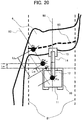
- Fig. 20 is a top view showing a method of setting another object-to-be-excavated end Pb.
- the terrain data acquisition section 31 sets a point at which a horizontal distance from the tip end Cf of the lower travel structure 10 (vertical distance in Fig. 20 ) becomes a minimum value on the object-to-be-excavated end datum line 83 as the object-to-be-excavated end Pb.
- the work assist system may be configured such that the side cross-sectional views described using Figs.
- the work assist system may be configured to display not the distance Lw but a distance Lw' on the monitor 21 if the object-to-be-excavated end Pb is set in this way.
- the distance Lw' is a work position distance in a front direction of the hydraulic excavator 1 between the work position Pw and the tip end Cf of the lower travel structure 10.
- the work assist system is not limited to the configuration such that the object-to-be-excavated end Pb is specified as the position at which the horizontal distance becomes the minimum value on the object-to-be-excavated end datum line 83.
- the work assist system may be configured such that a position at which an average value or a maximum value of the horizontal distance described above is specified as the object-to-be-excavated end Pb.
- the work assist system may be configured such that the above methods can be applied by being combined as appropriate by the setting input device 20.
- the work assist system may be configured such that a datum surface other than the datum surface 82 is set and that the second object-to-be-excavated end Pu is specified by using the other datum surface similarly to the object-to-be-excavated end Pb.
- the number of work positions output by the work position calculation section 30 to the monitor 21 is not limited to one, and the work position distance Lw and the stable work position distance Lws, for example, may be displayed simultaneously.
- the work position calculation section 30 is not limited to being implemented by the controller mounted in the hydraulic excavator 1. It may be configured such that an external computer performs necessary processes for calculating/displaying the stop position of the hydraulic excavator 1 and transmits the process result to the hydraulic excavator 1 via the wireless device 26. Furthermore, the setting input device 20 is not limited to being mounted to an interior of the operation room 17. It may be configured by a portable information terminal that can be carried by a supervisor or the like on a work site and that transmits various information to the hydraulic excavator 1 via the wireless device 26.
- a guidance display device for stopping the excavator 1 at the work position Pw or Pws is not limited to the monitor 21 described above.
- Fig. 21 is an overhead view showing the front of the hydraulic excavator 1 from within the operation room 17. Another method of guiding the excavator 1 to the work position Pw or Pws will be described using Fig. 21 .
- a head-up display 25 in which a computer that performs a control process related to video display is embedded and which displays a virtual video in such a manner as to be superimposed on a real image on a windshield glass 62 on a front surface of the operation room 17 is mounted in an upper portion of the operation room 17.
- the terrain data acquisition section 31 outputs a shape of the edge 86 of the excavator ground contact surface 85 to the head-up display 25.
- the head-up display 25 displays a target end shape 87 obtained by offsetting the shape of the edge 86 output from the terrain data acquisition section 31 toward the excavator by the work position distance Lw (or Lws) on the windshield glass 62 on the front surface of the operation room 17.
- the operator moves the excavator 1 so that the target end shape 87 coincides with the edge 86 of the surface to be excavated 4 while viewing the real image on the front surface, and then stops the excavator 1. It is thereby possible to stop the excavator 1 at the work position Pw or Pws.
- the guidance display device for guiding the excavator 1 to the work position Pw or Pws is not limited to the monitor 21 or the head-up display 25. It is possible to use the other display device such as a head-mounted display worn by the operator or a device that composites a video of an external camera with work position information and displays a composite video while the windshield glass is replaced by a monitor.
- the work assist system may be configured to cut off the output from the travel lever when the hydraulic excavator 1 reaches the work position or may be configured such that the hydraulic excavator 1 automatically moves to the work position by adding a specific input.
- the hydraulic excavator 1 has the upper swing structure 11, the boom 13, the arm 14, and the bucket 15.
- the configuration of the work device is not limited to this configuration, and the present embodiments are applicable to a hydraulic excavator equipped with a work device that can excavate the object to be excavated located below the ground contact surface.
- the present invention is not limited to the work assist system that includes all the configurations described in the above embodiments but encompasses those from which a part of the configurations is deleted.
- a part of the configurations according to some embodiment can be added to or can replace configurations according to the other embodiment.
- a part of or all of the configurations related to the controller 18 and functions, execution processes, and the like of the configurations may be realized by hardware (by designing logic for executing the functions, for example, by an integrated circuit, or the like). Moreover, a plurality of computers identical or different in an installation location may perform decentralized processing. Furthermore, the configurations related to the controller 18 may be implemented as a program (software) for realizing the functions related to the configurations of the controller 18 by causing an arithmetic processor (for example, a CPU) to read out and execute the program. Information related to the program can be stored in, for example, a semiconductor memory (such as a flash memory or an SSD), a magnetic storage device (such as a hard disk drive), or a recording medium (such as a magnetic disk or an optical disk).
- a semiconductor memory such as a flash memory or an SSD
- a magnetic storage device such as a hard disk drive
- a recording medium such as a magnetic disk or an optical disk.
Abstract
Description
- The present invention relates to a work assist system for a work machine for assisting locating of a work position of a self-propelled work machine.
- There is known a system for assisting work of a self-propelled work machine such as a hydraulic excavator by providing a position relationship between the work machine and an object to be excavated. As a system of this type, Japanese Patent No.
5202667 - Patent Document 1: Japanese Patent No.
5202667 - Meanwhile, in excavation work by a hydraulic excavator, often carried out is rough excavation that repeats an excavation operation in which the hydraulic excavator is placed on an object to be excavated and a work device (work arm) extends from an end portion of an upper surface of the object to be excavated to a height lower than a height of a travel structure of the excavator, and a retreat operation of the excavator after the excavation operation. In this case, a height (bench height) of the object to be excavated on which the excavator is placed sometimes changes depending on a location, a situation, a work progress, and the like. When it is desired to maintain work efficiency by keeping an excavation amount in one excavation operation despite a difference in the height of the object to be excavated and the object to be excavated is lower in height, the excavator needs to excavate the object to be excavated at a position at which the excavator is located farther from the end portion of the upper surface of the object to be excavated. In this way, as the height of the object to be excavated is lower, the optimum excavation position becomes farther from the end portion of the upper surface of the object to be excavated. In many cases, however, it is difficult for an operator on the excavator to visually know the height of the object to be excavated, or the operator can visually recognize the height but cannot accurately grasp the height. It is, therefore, difficult to continue excavation while stopping the excavator at the optimum excavation position in response to a change in the height of the object to be excavated.
- Excavation based on a bench cut method (step-by-step mining method) in a strip mine corresponds to a concrete example of the work carried out in the above situation. An object to be excavated in this case is called bench formed into a stepped shape with one or more steps.
- In relation to this problem, according to the hydraulic excavator position guidance system of Japanese Patent No.
5202667 - An object of the present invention is to provide a work assist system for a work machine capable of guiding the work machine to a position suited for keeping a work amount even when the work machine carries out work while being placed on an object to be excavated and a height of the object to be excavated changes.
- To solve such problems, a work assist system for a work machine according to the present invention is a work assist system for a self-propelled work machine, including: a controller configured to, on the basis of the assumed excavation amount in the one excavation operation of the work machine, determine a region in which an assumed excavation amount is obtained from an object to be excavated by one excavation operation of the work machine as a region to be excavated, and on the basis of the region to be excavated, calculate a work position of the work machine at which the work machine performs a next excavation operation; and a display device that displays information related to the work position.
- According to the present invention, a stop position is calculated in accordance with a height of an object to be excavated so as to keep an excavation amount, and it is, therefore, possible to easily guide a work machine to the stop position and to maintain work efficiency high.
-
-
Fig. 1 is an outside drawing showing an example of a configuration of a hydraulic excavator to which the present invention is applied. -
Fig. 2 is a schematic diagram showing a system configuration of a work assist system according to a first embodiment of the present invention. -
Fig. 3 is a hardware configuration diagram of acontroller 18. -
Fig. 4 is a bird's-eye view showing an example of excavation work of the hydraulic excavator, and showing a state in which the hydraulic excavator ends excavation of an object to be excavated and is loading diggings into a bucket. -
Fig. 5 is a bird's-eye view showing an example of the excavation work of the hydraulic excavator, and showing a state in which the hydraulic excavator swings after end of excavation, moves the bucket onto a cargo stand of a transporting machine, and is releasing the diggings. -
Fig. 6 is a side cross-sectional view showing a method of setting a work position with reference to a region to be excavated. -
Fig. 7 is a flowchart showing a method of displaying the work position according to the first embodiment of the present invention. -
Fig. 8 shows an example of a display screen showing the work position. -
Fig. 9 is a schematic diagram showing a system configuration of a work assist system according to a second embodiment of the present invention. -
Fig. 10 is a side cross-sectional view showing a method of setting a work position with reference to a stability of an object to be excavated. -
Fig. 11 is a side cross-sectional view showing a method of acquiring a shape of the object to be excavated. -
Fig. 12 is a side cross-sectional view showing a different method of acquiring the shape of the object to be excavated. -
Fig. 13 is a graph showing work positions relative to a height of the object to be excavated. -
Fig. 14 is a flowchart showing a method of displaying the work position according to the second embodiment of the present invention. -
Fig. 15 is a flowchart showing a method of displaying the work position according to a third embodiment of the present invention. -
Fig. 16 is a flowchart showing a method of displaying the work position according to a fourth embodiment of the present invention. -
Fig. 17 is a schematic diagram showing a work range of the work machine. -
Fig. 18 is a bird's-eye view showing a relationship between an object-to-be-excavated end datum line and an object-to-be-excavated end Pb. -
Fig. 19 is a top view showing a relationship between the object-to-be-excavated end datum line and the object-to-be-excavated end Pb. -
Fig. 20 is a top view showing a method of setting another object-to-be-excavated end Pb. -
Fig. 21 is an overhead view showing a front of the hydraulic excavator from within an operation room when the work position is indicated using a head-up display. - Embodiments of the present invention will be described hereinafter with reference to the drawings.
- Configurations of a work machine and a work assist system equipped in the work machine will be described using
Figs. 1 and2 . -
Fig. 1 is an outside drawing of a hydraulic excavator that is an example of a self-propelled work machine. Ahydraulic excavator 1 is configured with alower travel structure 10, anupper swing structure 11 swingably provided on thelower travel structure 10, aboom 13 rotatably provided in front of theupper swing structure 11, anarm 14 rotatably provided on a tip end of theboom 13, abucket 15 rotatably provided on a tip end of thearm 14, a multijoint type front work device (work device) 12 configured by theboom 13, thearm 14, and thebucket 15, anoperation room 17 in which an operator gets on board and operates theexcavator 1, operation lever (operation device) 19 (refer toFig. 9 ) provided within theoperation room 17 and used for operating thehydraulic excavator 1, and acontroller 18 exercising control over an operation of thehydraulic excavator 1 on the basis of an output (a hydraulic signal or an electrical signal) from theoperation lever 19. - The present embodiment is implemented on the assumption of excavation based on a bench cut method, and an object to be excavated by the
hydraulic excavator 1 is a bench formed into a stepped shape. The bench includes a bench upper surface (floor) 85 that is a flat surface on which thehydraulic excavator 1 is placed at a time of excavation work, and a surface to be excavated 4 that is a downward inclined surface (bench side surface) connected to the benchupper surface 85. In the bench ofFig. 1 , anedge 86 appears in a boundary portion between the benchupper surface 85 and the surface to be excavated 4. At the time of the excavation work, thehydraulic excavator 1 is placed on the benchupper surface 85 in such a manner that theedge 86 is located in front of the excavator, and excavates the surface to be excavated 4 while appropriately expanding or contracting thefront work device 12 from the position. - A
laser distance meter 24 that is a distance sensor which measures a distance to a surrounding object and that is a shape sensor for mainly detecting a surface shape of the object to be excavated (bench) is fixed to a front of theoperation room 17 at a predetermined angle (laser distance meter mounting angle) ad (refer toFig. 11 ) with respect to the excavatorground contact surface 85. Amonitor 21, asetting input device 20, and a work position display switch 27 (all of which will be described later) are equipped in theoperation room 17. Furthermore, theupper swing structure 11 is equipped with awireless device 26 that is a communication device for holding communication with an external device or an external computer, and a controller (control system) 18 that is a computer (for example, a microcomputer) configured to execute various information processes related to thehydraulic excavator 1. -
Fig. 2 is a schematic diagram showing a system configuration of a work assist system for a work machine mounted in thehydraulic excavator 1 and displaying a work position. Same sections as those in the preceding drawing are denoted by the same reference characters and description thereof is often omitted (the same thing is true for subsequent drawings). - The work assist system includes the
setting input device 20 that is an input device (a keyboard, a mouse, a plurality of buttons, a touch panel, and the like) for changing various types of setting of the work assist system; a workposition calculation section 30 that is configured as a program within thecontroller 18 and that calculates a stop position (often referred to as "work position") of thehydraulic excavator 1 for a next excavation operation; the monitor (display device) 21 that displays a work position Pw (refer toFig. 6 to be described later) or information related to the work position Pw (for example, a horizontal distance Lw (refer toFig. 6 ) from a tip end Cf (refer toFig. 6 ) of thelower travel structure 10 to the work position Pw, and the like); and the workposition display switch 27 that alternatively instructs a changeover between ON and OFF of the work position being displayed on the monitor 21 (or may alternatively between ON and OFF of work position calculation by the work position calculation section 30). -
Fig. 3 shows a hardware configuration of thecontroller 18. Thecontroller 18 has aninput section 91, a central processing unit (CPU) 92 that is a processor, a read only memory (ROM) 93 and a random access memory (RAM) 94 that are storage devices, and anoutput section 95. Information and signals are input to theinput section 91 from external devices (for example, thesetting input device 20, thelaser distance meter 24, and the work position display switch 27), and theinput section 91 performs A/D conversion as needed. TheROM 93 is a recording medium in which a program and the like are stored, and theCPU 92 performs a predetermined computation process on the signals imported from theinput section 91 and thememories ROM 93. Theoutput section 95 generates a signal for output in response to a computation result in theCPU 92, and outputs the signal to an external device (for example, the monitor 21). While thecontroller 18 ofFig. 3 includes the semiconductor memories, i.e., theROM 93 and theRAM 94 as the storage devices, thecontroller 18 may include a magnetic storage device such as a hard disk drive and store the program in this magnetic storage device. - Reference is made back to
Fig. 2 . The workposition calculation section 30 includes a terraindata acquisition section 31, a region-to-be-excavated determination section 32, and a workposition computing section 34. - The terrain
data acquisition section 31 is a section that acquires a position of an object-to-be-excavated end Pb (refer toFig. 6 ) that is a point on theedge 86 of the benchupper surface 85 and a height H (refer toFig. 6 ) of the benchupper surface 85 from anexcavation datum surface 82 on the basis of distance information output from thelaser distance meter 24. The object-to-be-excavated end Pb is a datum point at a time of calculating the work position Pw. The object-to-be-excavated end Pb may be defined in the boundary portion between the benchupper surface 85 and the surface to be excavated 4 and is not necessarily defined on theedge 86 as shown inFig. 6 and the like (refer toFigs. 19 and20 to be described later for details). - In the present embodiment, it is assumed that the "object-to-be-excavated end Pb" is a point at which a plane that passes through a swing center of the
excavator 1 and a center of thework device 12 intersects theedge 86 of the benchupper surface 85, and that the "datum surface 82" is a bench upper surface one step below the benchupper surface 85 on which theexcavator 1 is placed or a bench bottom surface on a lowermost step. - The region-to-
be-excavated determination section 32 is a section that determines a region in the object to be excavated (often referred to as "region to be excavated S") in which an assumed excavation amount (to be described later) is obtained from the object to be excavated by one excavation operation of theexcavator 1 on the basis of an acquisition result of the terraindata acquisition section 31. As described later in detail, in the present embodiment, the region-to-be-excavated determination section 32 determines the region to be excavated S on the basis of the height H of the benchupper surface 85 and an area sb (to be described later) that can be derived from the assumed excavation amount. - "One excavation operation" in the present description means a series of operations performed since a state in which a claw tip of the
bucket 15 touches the surface to be excavated 4 until a state in which a height of the claw tip of thebucket 15 reaches the benchupper surface 85 at the time of excavation of the bench. - Furthermore, the "assumed excavation amount" is set with reference to a capacity of the bucket 15 (bucket capacity). The bucket capacity varies by a model of the
hydraulic excavator 1. For example, as a concrete assumed excavation amount, a capacity (flat stack capacity) when the bucket is filled with diggings to a level of an upper edge of the bucket or a capacity (heap capacity) when diggings are further heaped up in the bucket from the flat stack state can be used. From the viewpoint of maximizing work efficiency, it is preferable to use the heap capacity as the assumed excavation amount. However, the assumed excavation amount is not limited to a specific capacity but an arbitrary value equal to or smaller than a maximum capacity can be adopted as the assumed excavation amount. In the present embodiment, it is assumed that the heap capacity is the assumed excavation amount. - The work
position computing section 34 is a section that calculates the work position (stop position) of thehydraulic excavator 1 for the next excavation operation on the basis of the region to be excavated S determined by the region-to-be-excavated determination section 32. As described later in detail, in the present embodiment, the workposition computing section 34 calculates a distance Lw from the datum point (object-to-be-excavated end Pb) defined on the boundary portion between the benchupper surface 85 and the surface to be excavated 4 to the work position Pw on the basis of the region to be excavated S, and calculates the work position Pw on the basis of the distance Lw. - Next, procedures through which the work assist system for the work machine sets the work position and an example of display of the work position will be described as an example of the embodiment of the present invention, using
Figs. 4 to 8 . -
Fig. 4 is a schematic diagram showing an example of the work of thehydraulic excavator 1, and showing a state in which thehydraulic excavator 1 ends excavation of the surface to be excavated 4 by one excavation operation and is loadingdiggings 5 into thebucket 15.Fig. 5 is a schematic diagram showing a state in which thehydraulic excavator 1 swings after end of one excavation operation, moves thebucket 15 onto a cargo stand of a transporting machine (dump truck) 2, and is releasing thediggings 5. Generally, thehydraulic excavator 1 alternately repeats excavation work and loading work shown inFigs. 4 and5 until the cargo stand of the transportingmachine 2 is filled to capacity. Furthermore, when the excavation work is over in a region having a longitudinal excavation width Wd and present in a direction of theedge 86 in front of thehydraulic excavator 1, thehydraulic excavator 1 retreats and repeats the excavation work and the loading work again. At this time, when a predetermined excavation amount is to be kept in each excavation operation and a position of thehydraulic excavator 1 is close to a position of the object-to-be-excavated end 7, the predetermined excavation amount cannot be often secured in order to prevent a position of thebucket 15 at a time of the end of the one excavation operation from reaching a foothold of thehydraulic excavator 1. -
Fig. 6 is a side cross-sectional view showing a position relationship between thehydraulic excavator 1 and the surface to be excavated 4 (bench cross-sectional view taken by the plane passing through the swing center of thehydraulic excavator 1 and the center of the work device 12).Fig. 7 is a flowchart showing processes performed by the workposition calculation section 30. Procedures for displaying the distance Lw to the work position Pw on themonitor 21 will next be described usingFig. 7 while referring toFig. 6 . - When the processes of
Fig. 7 are started, the workposition calculation section 30 determines first whether the workposition display switch 27 is ON in Step S100. When the workposition display switch 27 is not ON, the workposition calculation section 30 ends the processes without displaying anything on themonitor 21. - On the other hand, when the work
position display switch 27 is ON, the region-to-be-excavated determination section 32 acquires the height H and the position of the object-to-be-excavated end Pb from the terraindata acquisition section 31 in Step 101 and proceeds to Step 102. - In
Step 102, the region-to-be-excavated determination section 32 determines first the region to be excavated S on the basis of the area sb of the region to be excavated S in the side cross-sectional view ofFig. 6 and the height H acquired by the terraindata acquisition section 31, and thereby calculates an excavation amount setting distance Ls. In the present embodiment, the region to be excavated S is simplified as a parallelogram that passes through two points Pb and Pu associated with the surface to be excavated 4 and that has the constant area sb, as shown inFig. 6 . The area sb of the region to be excavated S is determined from the assumed excavation amount, and a position of an upper left vertex Pa of the parallelogram (in other words, a length of an upper side and a bottom side of the parallelogram) changes in response to a value of the height H. Owing to this, the excavation amount setting distance Ls that is the length of the upper side and the bottom side of the parallelogrammatic region to be excavated S can be calculated from sb and H by the following Equation (1).
- Next, the work
position computing section 34 calculates the distance Wd (often referred to as "longitudinal excavation width") from the object-to-be-excavated end Pb to the work position Pw by the following Equation (2). Moreover, the workposition computing section 34 calculates the work position Pw from the distance Wd and the position of the object-to-be-excavated end Pb. Lm in Equation (2) denotes a margin distance. The workposition computing section 34 according to the present embodiment computes the work position Pw not as the point Pa but as a position moved from the point Pa toward thehydraulic excavator 1 by the margin distance Lm set by the settinginput device 20.
- Furthermore, the work
position computing section 34 computes the work position distance Lw that is the horizontal distance from the tip end Cf of thelower travel structure 10 of thehydraulic excavator 1 to the work position Pw. The work position distance Lw is represented by the following Equation (3) using a distance Lb (often referred to as "object-to-be-excavated end distance") from the tip end Cf of thelower travel structure 10 of thehydraulic excavator 1 to the object-to-be-excavated end Pb. The distance Lb is acquired by the terraindata acquisition section 31 via thelaser distance meter 24 or thewireless device 26.
- Setting the region to be excavated S as the parallelogram as described above has a merit that it is possible to identify the work position Pw and calculate the work position distance Lw if the position of the object-to-be-excavated end Pb and the value of the height H can be acquired.
- It is noted that calculation of the longitudinal excavation width Wd is not limited to the above calculation method. The work
position calculation section 30 may be configured such that the longitudinal excavation width Wd is set on the basis of a calculation equation that varies depending on the settinginput device 20. - Finally, the work
position calculation section 30 outputs the distance Lw to themonitor 21 in Step 103 and ends the processes. -
Fig. 8 shows an example of display of the distance Lw to the work position Pw on themonitor 21 equipped in theoperation room 17. A method of displaying the work position Pw will be described usingFig. 8 . - On a screen of the
monitor 21 shown inFig. 8 , a monitorupper section 22 and a monitorlower section 23 are provided as display regions. - On the monitor
upper section 22, the work position distance Lw from the tip end of thelower travel structure 10 to the work position is displayed as a numerical value on the basis of an output from the workposition calculation section 30 described usingFig. 7 . The numerical value (-0.5m) displayed on a right-hand side of a character string of "UP TO FRONT END" in the example ofFig. 8 indicates the distance Lw to the work position Pw. - In the example of
Fig. 8 , the distance Lw is a negative value. The distance Lw which is negative as shown in the example ofFig. 8 indicates that the tip end Cf of thelower travel structure 10 goes beyond the work position Pw and that thehydraulic excavator 1 should retreat. Conversely, the distance Lw which is positive indicates that the tip end Cf of thelower travel structure 10 does not reach the work position Pw and that thehydraulic excavator 1 should move forward. If the distance Lw is negative, it is preferable that awarning image 42 is displayed on the screen to alert the operator as shown inFig. 8 . A warning message may be displayed as an alternative to thewarning image 42. In addition, an audio output device that outputs a warning tone or a warning voice as an alternative to thewarning image 42 may be additionally installed in a similar case. - On the monitor
lower section 23, an image of the side cross-sectional view of thehydraulic excavator 1 similar to that ofFig. 6 (a surface shape image of the object to be excavated) is displayed. As for display on the monitorlower section 23, a workposition display line 84 that indicates the work position Pw, the region to be excavated S, and an image of thehydraulic excavator 1 are displayed in such a manner as to be superimposed on the image of the side cross-sectional view on the basis of the output from the workposition calculation section 30. The image of the side cross-sectional view is generated by thecontroller 18 on the basis of the surface shape of the object to be excavated detected by thelaser distance meter 24. It is preferable that the workposition calculation section 30 is configured such that an image position of the hydraulic excavator and a posture of an image of the work device on the monitorlower section 23 are interlocked with a position and a posture of a real machine. - In this way, displaying the work position Pw and the image of the
hydraulic excavator 1 makes it possible to facilitate grasping the position relationship between the work position Pw and thehydraulic excavator 1. Furthermore, displaying the region to be excavated S makes it possible to grasp a target track of the claw tip of thebucket 15 at the time of the next excavation operation and, therefore, to contribute to maximizing the excavation capacity and maintaining the work efficiency high. - As described above, the work assist system for the work machine according to the present embodiment is configured to determine the region to be excavated S on the basis of the bench height H and the assumed excavation amount in such a manner that the cross-sectional area sb of a region excavated in each of a plurality of excavation operations can be kept constant, and to calculate the position of the
excavator 1 suited for excavation in the next excavation operation as the work position Pw on the basis of the region to be excavated S. In addition, the work assist system is configured to calculate the distance Lw from the frontmost end Cf of thelower travel structure 10 of thehydraulic excavator 1 to the work position Pw and to display the distance Lw on themonitor 21. Displaying the distance Lw in this way makes it possible for the operator to easily grasp the position relationship between the work position suited for the bench height H and thehydraulic excavator 1. It is thereby possible to guide thehydraulic excavator 1 to the position suited for keeping the excavation amount even when the bench height changes, and it is, therefore, possible to maintain the work efficiency high. - It is noted that the shape of the region to be excavated S is not limited to the parallelogram shown in
Fig. 6 . The work assist system may be configured such that the shape of the region to be excavated S is changeable into another shape by the settinginput device 20. In this case, the excavation amount setting distance Ls is calculated using an equation other than Equation (1) described above. However, the distance Ls can be calculated from the area sb (assumed excavation amount) and the shape of the object to be excavated as long as the shape of the region to be excavated S is determined in advance. For example, the work assist system may be configured such that a trapezoid having part of the excavatorground contact surface 85 as an upper base, part of thedatum surface 82 as a lower base, and a perpendicular to the excavatorground contact surface 85 and the surface to be excavated 4 as legs is set as the region to be excavated S. Alternatively, the work assist system may be configured such that a model form of a moving locus of the claw tip of thebucket 15 when the region having the cross-sectional area sb is excavated in one excavation operation is stored per height H, and that the shape of the region to be excavated S is selected as appropriate on the basis of the model form of the moving locus and the height H. - The work assist system has been described above on the assumption that the excavation operation starts by striking the claw tip of the
bucket 15 on a point Pu located as a lower end of the surface to be excavated 4. However, it is assumed that when the bench height H is large and the point Pu is located outside of a movable range of thebucket 15, the region to be excavated S is set in such a manner that an intersecting point between a maximum range of the movable range of thebucket 15 and the surface to be excavated 4 serves as a start point of the excavation operation. In other words, the present embodiment is applicable even to a case in which the claw tip of thebucket 15 does not reach the point Pu. - If a concrete surface shape of the surface to be excavated 4 can be grasped (if the concrete surface shape can be grasped on site by the
laser distance meter 24 or the like or if the concrete surface shape can be grasped in advance from information such as a working drawing), the surface shape may be used as the shape of the surface to be excavated 4 at a time of estimating the region to be excavated S and calculating the work position Pw. In this case, estimation accuracy for the region to be excavated S improves and accuracy for the work position Pw, therefore, improves. In addition, accuracy for the side cross-sectional view displayed on the monitorlower section 23 can improve. - A device that acquires the shape of the object to be excavated is not limited to the
laser distance meter 24 but may be a device configured differently to be able to acquire the shape of the object to be excavated. For example, a distance surveying camera or an ultrasonic sensor can be used as an alternative to thelaser distance meter 24. Furthermore, the work assist system may be configured to make work position setting using the terrain data acquired from an external computer via thewireless device 26. For example, the work assist system may be configured such that the height H is set on the basis of a work scheme acquired from a site manager at a time of acquiring the height H, or that the height H is measured by the transportingmachine 2 from below the object to be excavated and transmitted to thehydraulic excavator 1. Moreover, the work assist system may be configured such that the shape of the surface to be excavated 4 at the time of the next excavation is estimated from the locus of the claw tip of thehydraulic excavator 1. - The margin distance Lm is not necessarily set at the time of calculating the longitudinal excavation width Wd (work position Pw) but may be set to zero. If the margin distance Lm is zero, the distance between the object-to-be-excavated end Pb and the work position Pw coincides with the excavation amount setting distance Ls and becomes a minimum distance.
- Contents of display on the
monitor 21 are not limited to contents described above. The work assist system may be configured, for example, such that a top view of the object to be excavated including the surface to be excavated 4 and theground contact surface 85 and thehydraulic excavator 1 is displayed on the monitorlower section 23 and work positions Pw and Pws are displayed in such a manner as to be superimposed on the top view. -
Fig. 9 is a schematic diagram showing another system configuration of the work assist system for the work machine mounted in thehydraulic excavator 1 and displaying the work position. The workposition calculation section 30 in this drawing includes, in addition to the configurations equipped in the workposition calculation section 30 shown inFig. 2 , a stableregion setting section 33, a travellingdetermination section 35, and adisplay update section 36. - The terrain
data acquisition section 31 is a section that acquires the shape of the object to be excavated on the basis of the distance information output from thelaser distance meter 24 and the terrain data obtained by thewireless device 26, and further acquires the height H of the object to be excavated, the position of the object-to-be-excavated end Pb, the shape of the surface to be excavated 4, and the like. The stableregion setting section 33 is a section that calculates a region (often referred to as "stable region") in which thehydraulic excavator 1 can stably carry out the excavation work on an upper surface of the object to be excavated on the basis of the surface shape of the object to be excavated and a stabilizing angle "as" (refer toFig. 10 ). The workposition computing section 34 is a section that computes the work position (Pw or Pws) of thehydraulic excavator 1. The travellingdetermination section 35 is a section that determines whether a travel instruction has been issued to thehydraulic excavator 1 on the basis of an output from the operation lever (operation device) 19. Thedisplay update section 36 is a section that updates the information (for example, the distance Lw to the work position Pw or a distance Lws to the work position Pws) related to the work position (Pw or Pws) and the region to be excavated output from the workposition computing section 34 on the basis of a determination of the travellingdetermination section 35 and displayed on themonitor 21. -
Fig. 10 is a side cross-sectional view showing a position relationship between thehydraulic excavator 1 and the surface to be excavated 4 according to a second embodiment. A method of calculating the second work position Pws determined on the basis of the stable region will be described usingFig. 10 . - A second object-to-be-excavated end Pu located on a lower edge of the surface to be excavated 4 is acquired by the terrain
data acquisition section 31. Next, a method of acquiring, by the terraindata acquisition section 31, a surface shape of the surface to be excavated 4 including the second object-to-be-excavated end Pu will be described usingFig. 11 . -
Fig. 11 is a side cross-sectional view showing a position relationship among thehydraulic excavator 1, thelaser distance meter 24, and the surface to be excavated 4. Thelaser distance meter 24 divides the surface to be excavated 4 into a point group, and outputs a point group relative horizontal distance Ln that is a relative horizontal distance of each point to thelaser distance meter 24 and a point group relative vertical distance Hn. The terraindata acquisition section 31 stores a laser distance meter mounting length Ld of thelaser distance meter 24, a laser distance meter mounting height Hd with respect to the excavatorground contact surface 85, and the laser distance meter mounting angle ad with respect to the excavatorground contact surface 85. The terraindata acquisition section 31 converts an output from the laser distance meter 24 (the point group relative horizontal distance Ln and the point group relative vertical distance Hn) into a point group horizontal distance Ln' and a point group vertical distance Hn' with respect to the tip end Cf of thelower travel structure 10 on the basis of the mounting information of the laser distance meter 24 (length Ld, height Hd, and angle ad). Ln' and Hn' are obtained by conversion by the following Equation (7) using a rotation matrix.
- The terrain
data acquisition section 31 acquires the surface shape of the object to be excavated with respect to the tip end Cf of thelower travel structure 10 by conducting similar calculation for all the points included in the point group. While the shape of the surface to be excavated 4 is described as a two-dimensional shape in a side cross-section in the description usingFig. 11 , the shape may be converted into a three-dimensional shape of the object to be excavated by using a three-dimensional rotation matrix. - The terrain
data acquisition section 31 calculates all of tilts between two adjacent points among the point group constituting the surface to be excavated 4, and detects points Ptop and Pbtm for which the tilt radidly changes. The terraindata acquisition section 31 outputs and stores the point Ptop having a larger altitude as the object-to-be-excavated end Pb and the point Pbtm having a smaller altitude as the second object-to-be-excavated end Pu on the basis of the altitudes of the points Ptop and Pbtm. The terraindata acquisition section 31 also outputs and stores a difference between the altitudes of the points Ptop and Pbtm as the height H. - Another method of acquiring positions of the object-to-be-excavated end Pb and the second object-to-be-excavated end Pu will next be described using
Fig. 12. Fig. 12 is a side cross-sectional view showing the method of acquiring the positions of the object-to-be-excavated ends Pb and Pu on the basis of the locus of the claw tip of thebucket 15 in the excavation work. - The
front work device 12 is equipped with a boom angle sensor 28-1 (not shown), an arm angle sensor 28-2, and a bucket angle sensor 28-3 measuring rotation angles of theboom 13, thearm 14, and thebucket 15, and an armcylinder pressure sensor 29 measuring an internal pressure of thearm cylinder 16. Furthermore, thecontroller 18 stores dimensions of theboom 13, thearm 14, and thebucket 15, and is configured to be able to compute a position of the claw tip of thebucket 15 on the basis of these dimensions and outputs from the angle sensors 28-1, 28-2, and 28-3. - When acquiring the positions of the object-to-be-excavated end Pb and the second object-to-be-excavated end Pu, the
controller 18 first monitors an output from thepressure sensor 29, determines time at which a load of thearm cylinder 16 increases to be greater than a predetermined value as start of excavation, and sets the position of the claw tip of thebucket 15 at that time as the second object-to-be-excavated end Pu. Thecontroller 18 then monitors the position of the claw tip of thebucket 15 after the start of excavation, determines time at which a height of the claw tip of thebucket 15 becomes larger than a height of the excavatorground contact surface 85 as end of excavation, and sets the position of the claw tip of thebucket 15 at that time as the object-to-be-excavated end Pb. - Reference is made back to
Fig. 10 . The stabilizing angle (repose angle) "as" is a maximum tilt angle of the surface to be excavated 4 of the bench at which the surface to be excavated 4 is spontaneously stable without sliding, and is set for the second object-to-be-excavated end Pu. A value of the stabilizing angle "as" varies depending on a soil quality of the bench and is stored in a storage device within thecontroller 18 in advance via the settinginput device 20 or the like. The stableregion setting section 33 calculates a horizontal distance Lst (often referred to as "object-to-be-excavated stable distance") from the second object-to-be-excavated end Pu to the position Pws at which the object to be excavated become stable using the stabilizing angle "as" and the height H on the basis of the following Equation (4).
- Next, the work
position computing section 34 calculates a horizontal distance Lws (often referred to as "second work position distance") from the tip end Cf of thelower travel structure 10 to the second work position Pws. The second work position distance Lws is represented by the following Equation (5) using a horizontal distance Lu from the tip end Cf of thelower travel structure 10 to the second object-to-be-excavated end Pu. It is noted that the horizontal distance Lu is acquired by the terraindata acquisition section 31 via thelaser distance meter 24 or thewireless device 26.
- At this time, a horizontal distance Wds (often referred to as "second longitudinal excavation width") from the object-to-be-excavated end Pb to the second work position Pws is represented by the following Equation (6) using a horizontal distance Lb (often referred to as "object-to-be-excavated end distance") from the tip end Cf of the
lower travel structure 10 of thehydraulic excavator 1 to the object-to-be-excavated end Pb.
- The work
position computing section 34 compares a magnitude of the second longitudinal excavation width Wds with a magnitude of the longitudinal excavation width Wd and sets the position using the larger longitudinal excavation width as the work position. For example, when the second longitudinal excavation width is larger, the workposition computing section 34 sets the position Pws using the second longitudinal excavation width Wds as the work position. -
Fig. 13 is a graph showing values of the longitudinal excavation width Wd and the second longitudinal excavation width Wds relative to the height H. Changes of the longitudinal excavation width Wd and the second longitudinal excavation width Wds calculated on the basis of the method described above with the height H will be described usingFig. 10 . - As already described, as the height H is smaller, the work position distance Ls necessary to secure the predetermined area sb becomes longer and, at the same time, the longitudinal excavation width Wd becomes larger, so that the work position Pw is farther from the object-to-be-excavated end Pb. On the other hand, as the height H is larger, the excavation amount setting distance Ls necessary to secure the predetermined area sb becomes shorter and, at the same time, the longitudinal excavation width Wd becomes smaller, so that the work position Pw is closer to the object-to-be-excavated end Pb.
- The object-to-be-excavated stable distance Lst increases as the height H increases. Therefore, the second longitudinal excavation width Wds increases as the height H increases. The work
position computing section 34 compares the longitudinal excavation width Wd with the second longitudinal excavation width Wds and sets the position using the larger value as the work position. As shown inFig. 13 , (A) in a region in which the height H is smaller than H2, the longitudinal excavation width Wd is larger and the work position Pw using the longitudinal excavation width Wd is, therefore, output. (B) When the height H is H2, the longitudinal excavation width Wd is identical to the second longitudinal excavation width Wds. For the sake of convenience, therefore, the work position Pw using the longitudinal excavation width Wd is output (or the second work position Pws may be output). (C) In a region in which the height H is larger than H2, the second longitudinal excavation width Wds is larger and the second work position Pws using the second longitudinal excavation width Wds is, therefore, output. -
Fig. 14 is a flowchart showing processes performed by the workposition calculation section 30 according to the second embodiment. A method of displaying the work position will be described usingFig. 14 . Same processes as those in the preceding drawing (Fig. 7 ) are denoted by the same numbers and description thereof is often omitted (the same thing is true for subsequent flowcharts). - When the work
position display switch 27 is ON, the region-to-be-excavated determination section 32 and the stableregion setting section 33 acquire the terrain data (for example, the height H, the positions of the object-to-be-excavated ends Pb and Pu, the horizontal distance Lu, and the shape of the surface to be excavated 4) necesary to determine the work positions Pw and Pws and to compute the longitudinal excavation widths Wd and Wds from the terraindata acquisition section 31 in Step 101A. - Next, in
step 102A, the region-to-be-excavated determination section 32 estimates the region to be excavated S by the method already described. The workposition computing section 34 calculates the excavation amount setting distance Ls using the area sb, the height H, and the above Equation (1), adds the margin Lm to the excavation amount setting distance Ls to calculate the longitudinal excavation width Wd (above Equation (2)). - Furthermore, the stable
region setting section 33 calculates the object-to-be-excavated stable distance Lst using the above Equation (4). The workposition computing section 34 calculates the second work position distance Lws using the above Equation (5), and calculates the second longitudinal excavation width Wds using the above Equation (6) . - Moreover, the work
position computing section 34 compares the magnitudes of the two longitudinal excavation widths Wd and Wds with each other, computes the distance (Lw or Lws) to the work position (Pw or Pws) related to the larger longitudinal excavation width, and outputs the distance to thedisplay update section 36. - Firnally, the
display update section 36 outputs the distance (Lw or Lws) to themonitor 21 in Step 103A and the workposition calculation section 30 ends the processes. It is noted that a display form of the distance (Lw or Lws) on themonitor 21 is assumed as the same as that shown inFig. 8 and description thereof is omitted. - As described above, the work assist system for the work machine according to the present embodiment compares the magnitude of the longitudinal excavation width Wd calculated on the basis of the region to be excavated S with the magnitude of the second longitudinal excavation width Wd derived on the basis of the stabilizing angle "as" of the object to be excavated, and displays the distance (Lw or Lws) to the work position (Pw or Pws) related to the larger longitudinal excavation width on the
monitor 21. With such a configuration, thehydraulic excavator 1 is always disposed in the stable region, so that continuation of the stable excavation work is ensured. - A configuration of a work assist system for a work machine according to the present embodiment is assumed as the same as that shown in
Fig. 9 .Fig. 15 is a flowchart showing processes performed by the workposition calculation section 30 according to a third embodiment. - The processes up to Step 101A are similar to those in the preceding flowchart. In
Step 112, the terraindata acquisition section 31 determines whether the surface shape of the object to be excavated is changed on the basis of the terrain data acquired in Step 101A. When the surface shape of the object to be excavated is not changed, the workposition calculation section 30 returns to Step S100. When the surface shape of the object to be excavated is changed, the workposition calculation section 30 proceeds toSteps 102A and 103A. Thedisplay update section 36 displays the distance Lw or Lws on themonitor 21 and updates the display screen. After update of the display screen of themonitor 21, the workposition calculation section 30 returns to Step S100 and repeats the processes already described. - In this way, the work assist system for the work machine according to the present embodiment updates monitor display of the distance (Lw or Lws) to the work position for the next excavation operation when it is confirmed that the surface shape of the object to be excavated has changed. If the system is configured in this way, then the distance to the work position is automatically updated as the shape of the object to be excavated changes, and the work efficiency can be, therefore, improved.
- A configuration of a work assist system for a work machine according to the present embodiment is also assumed as the same as that shown in
Fig. 9 .Fig. 16 is a flowchart showing processes performed by the workposition calculation section 30 according to a fourth embodiment. - The processes up to Step 101A are similar to those in the preceding flowchart. In Step 122, the travelling
determination section 35 determines whether an input from a lever (travel lever) for instructing thehydraulic excavator 1 to travel has been done via theoperation lever 19. When the input from the travel lever (instruction of moving forward or retreat of the lower travel structure 10) has not been done, the workposition calculation section 30 returns to Step S100 in a state in which the distance (Lw or Lws) to the work position for the next excavation operation is maintained displayed on themonitor 21. When the input from the travel lever have been done, the workposition calculation section 30 proceeds to Step 102A and 103A. Thedisplay update section 36 displays the distance Lw or Lws on themonitor 21 and updates the display screen. After update of the display screen of themonitor 21, the workposition calculation section 30 returns to Step S100 and repeats the processes already described. - In this way, the work assist system for the work machine according to the present embodiment continues to update the monitor display of the distance (Lw or Lws) to the work position for the next excavation operation while the input from the travel lever is done. If the system is configured in this way, then the distance to the work position is automatically updated as the
hydraulic excavator 1 moves by the travel lever, and the work efficiency can be, therefore, improved. - While the configuration of updating the distance on the basis of presence or absence of the lever input from the
operation lever 19 is adopted in the present embodiment, a configuration of detecting the operation of thelower travel structure 10 that is a travel device of thehydraulic excavator 1 and updating the distance may be adopted. Similarly, a configuration of detecting an operation of a drive source (a hydraulic motor or an electric motor) of thelower travel structure 10 and updating the distance may be adopted. Furthermore, for example, a position of the transporting machine (dump truck) is monitored and the distance may be updated at timing of detecting that the transporting machine starts to move. Moreover, an operation that acts as a trigger for the update of the display is not limited to travelling but the display may be updated with reference to another operation. For example, operations of the hydraulic excavator are classified into an excavation operation, a swing operation, and a loading operation, and the work assist system may be configured to update the work position after the loading operation is detected. - The third embodiment and the fourth embodiment described above can be combined. That is, the work assist system may be configured to calculate anew the distance to the work position for the next excavation operation and display the calculation result on the
monitor 21 when at least one of followings is confirmed: a change of the surface shape of the object to be excavated; an input from the travel lever; and an operation of the lower travel structure 10 (an operation of the hydraulic excavator 1). - Meanwhile, the method of setting the object-to-be-excavated ends Pb and Pu is not limited to the above method. Another method of setting, by the terrain
data acquisition section 31, the object-to-be-excavated end Pb will be described usingFigs. 17 to 19 .Fig. 17 is a bird's-eye view showing a work range for thehydraulic excavator 1 and the surface to be excavated 4.Fig. 18 is a bird's-eye view showing an object-to-be-excavatedend datum line 83 generated by intersection between the datum surface (datum altitude surface) 82 and the surface to be excavated 4 when thedatum surface 82 is set with respect to the excavatorground contact surface 85 of thehydraulic excavator 1.Fig. 19 is a top view showing a relationship among thehydraulic excavator 1, the object-to-be-excavatedend datum line 83 shown inFig. 18 , and the object-to-be-excavated end Pb. - As shown in
Fig. 17 , the terraindata acquisition section 31 sets awork range 81 that specifies a movable range of thehydraulic excavator 1 in a horizontal direction when thehydraulic excavator 1 faces a direction of the surface to be excavated 4 on the basis of set values of the settinginput device 20, by two planes parallel to each other. Next, as shown inFig. 18 , the settinginput device 20 sets the horizontal surface (datum surface) 82 at a height in the vicinity of theground contact surface 85 as an alternative to the excavatorground contact surface 85 in such a manner that thedatum surface 82 intersects the surface to be excavated 4. The object-to-be-excavatedend datum line 83 located between the two planes that specify thework range 81 and generated by intersection between the surface to be excavated 4 and thedatum surface 82 is acquired. Next, as shown inFig. 19 , an intersecting point between aplane 89 that passes through a swing center Po of thehydraulic excavator 1 and that is parallel to the two planes specifying thework range 81 and the object-to-be-excavatedend datum line 83 is set as the object-to-be-excavated end Pb. - By setting the
datum surface 82 and setting the object-to-be-excavated end Pb in this way, it is possible to set the object-to-be-excavated end Pb even if the edge 86 (refer toFig. 1 ) of the bench upper surface cannot be detected by, for example, thelaser distance meter 24 or the like (for example, if theground contact surface 85 smoothly transitions to the surface to be excavated 4). - Furthermore, as shown in
Fig. 20 , the object-to-be-excavated end Pb may be set using another position on the object-to-be-excavatedend datum line 83.Fig. 20 is a top view showing a method of setting another object-to-be-excavated end Pb. In an example of this drawing, the terraindata acquisition section 31 sets a point at which a horizontal distance from the tip end Cf of the lower travel structure 10 (vertical distance inFig. 20 ) becomes a minimum value on the object-to-be-excavatedend datum line 83 as the object-to-be-excavated end Pb. The work assist system may be configured such that the side cross-sectional views described usingFigs. 6 and10 each use aplane 90 passing through the swing center Po of thehydraulic excavator 1 and the object-to-be-excavated end Pb as shown inFig. 20 . Furthermore, the work assist system may be configured to display not the distance Lw but a distance Lw' on themonitor 21 if the object-to-be-excavated end Pb is set in this way. The distance Lw' is a work position distance in a front direction of thehydraulic excavator 1 between the work position Pw and the tip end Cf of thelower travel structure 10. - Moreover, the work assist system is not limited to the configuration such that the object-to-be-excavated end Pb is specified as the position at which the horizontal distance becomes the minimum value on the object-to-be-excavated
end datum line 83. For example, the work assist system may be configured such that a position at which an average value or a maximum value of the horizontal distance described above is specified as the object-to-be-excavated end Pb. Alternatively, the work assist system may be configured such that the above methods can be applied by being combined as appropriate by the settinginput device 20. Furthermore, the work assist system may be configured such that a datum surface other than thedatum surface 82 is set and that the second object-to-be-excavated end Pu is specified by using the other datum surface similarly to the object-to-be-excavated end Pb. - The number of work positions output by the work
position calculation section 30 to themonitor 21 is not limited to one, and the work position distance Lw and the stable work position distance Lws, for example, may be displayed simultaneously. - The work
position calculation section 30 is not limited to being implemented by the controller mounted in thehydraulic excavator 1. It may be configured such that an external computer performs necessary processes for calculating/displaying the stop position of thehydraulic excavator 1 and transmits the process result to thehydraulic excavator 1 via thewireless device 26. Furthermore, the settinginput device 20 is not limited to being mounted to an interior of theoperation room 17. It may be configured by a portable information terminal that can be carried by a supervisor or the like on a work site and that transmits various information to thehydraulic excavator 1 via thewireless device 26. - Meanwhile, a guidance display device for stopping the
excavator 1 at the work position Pw or Pws is not limited to themonitor 21 described above.Fig. 21 is an overhead view showing the front of thehydraulic excavator 1 from within theoperation room 17. Another method of guiding theexcavator 1 to the work position Pw or Pws will be described usingFig. 21 . - In
Fig. 21 , a head-updisplay 25 in which a computer that performs a control process related to video display is embedded and which displays a virtual video in such a manner as to be superimposed on a real image on awindshield glass 62 on a front surface of theoperation room 17 is mounted in an upper portion of theoperation room 17. The terraindata acquisition section 31 outputs a shape of theedge 86 of the excavatorground contact surface 85 to the head-updisplay 25. The head-updisplay 25 displays atarget end shape 87 obtained by offsetting the shape of theedge 86 output from the terraindata acquisition section 31 toward the excavator by the work position distance Lw (or Lws) on thewindshield glass 62 on the front surface of theoperation room 17. The operator moves theexcavator 1 so that thetarget end shape 87 coincides with theedge 86 of the surface to be excavated 4 while viewing the real image on the front surface, and then stops theexcavator 1. It is thereby possible to stop theexcavator 1 at the work position Pw or Pws. - The guidance display device for guiding the
excavator 1 to the work position Pw or Pws is not limited to themonitor 21 or the head-updisplay 25. It is possible to use the other display device such as a head-mounted display worn by the operator or a device that composites a video of an external camera with work position information and displays a composite video while the windshield glass is replaced by a monitor. - Meanwhile, a case in which the distance Lw or Lws from the tip end Cf of the
lower travel structure 10 to the work position is displayed on themonitor 21 has been mainly described above. However, other information including an example of thetarget end shape 87 shown inFig. 21 may be displayed if the information is related to the work position. Furthermore, an output result of the work position is not limited to use for "display" but may be used for "operation assist." For example, the work assist system may be configured to cut off the output from the travel lever when thehydraulic excavator 1 reaches the work position or may be configured such that thehydraulic excavator 1 automatically moves to the work position by adding a specific input. - The present invention is not limited to the above embodiments but encompasses various modifications without departing from the spirit of the invention. For example, the
hydraulic excavator 1 has theupper swing structure 11, theboom 13, thearm 14, and thebucket 15. However, the configuration of the work device is not limited to this configuration, and the present embodiments are applicable to a hydraulic excavator equipped with a work device that can excavate the object to be excavated located below the ground contact surface. Moreover, the present invention is not limited to the work assist system that includes all the configurations described in the above embodiments but encompasses those from which a part of the configurations is deleted. Furthermore, a part of the configurations according to some embodiment can be added to or can replace configurations according to the other embodiment. - A part of or all of the configurations related to the
controller 18 and functions, execution processes, and the like of the configurations may be realized by hardware (by designing logic for executing the functions, for example, by an integrated circuit, or the like). Moreover, a plurality of computers identical or different in an installation location may perform decentralized processing. Furthermore, the configurations related to thecontroller 18 may be implemented as a program (software) for realizing the functions related to the configurations of thecontroller 18 by causing an arithmetic processor (for example, a CPU) to read out and execute the program. Information related to the program can be stored in, for example, a semiconductor memory (such as a flash memory or an SSD), a magnetic storage device (such as a hard disk drive), or a recording medium (such as a magnetic disk or an optical disk). -
- 1:
- Hydraulic excavator
- 10:
- Lower travel structure
- 12:
- Front work device
- 16:
- Operation room
- 18:
- Controller (control system)
- 19:
- Operation lever (operation device)
- 21:
- Monitor (display device)
- 24:
- Laser distance meter (shape sensor)
- 30:
- Work position calculation section
- 31:
- Terrain data acquisition section
- 32:
- Region-to-be-excavated determination section
- 34:
- Work position computing section
- 35:
- Travelling determination section
- 36:
- Display update section
- 82:
- Datum surface
- 83:
- Object-to-be-excavated end datum line
- 85:
- Bench upper surface (upper surface)
- H:
- Height from
datum surface 82 - as:
- Stabilizing angle
- S:
- Region to be excavated
- Pb:
- Object-to-be-excavated end (datum point)
- Pw, Pws:
- Work position
- Lw, Lws:
- Work position distance
Claims (5)
- A work assist system for a self-propelled work machine, comprising:a controller configured toon the basis of an assumed excavation amount in one excavation operation of the work machine, determine a region in which the assumed excavation amount is obtained from an object to be excavated by the one excavation operation of the work machine as a region to be excavated, andon the basis of the region to be excavated, calculate a work position of the work machine at which the work machine performs a next excavation operation; anda display device that displays information related to the work position.
- The work assist system for the work machine according to claim 1, wherein
the object to be excavated includesan upper surface on which the work machine is placed at a time of excavation work, anda surface to be excavated that is a downward inclined surface connected to the upper surface, andthe controller is configured todetermine the region to be excavated on the basis of a height of the upper surface from a datum surface and the assumed excavation amount,calculate a distance to the work position from a datum point that is defined in a boundary portion between the upper surface and the surface to be excavated on the basis of the region to be excavated, andcalculate the work position on the basis of the distance. - The work assist system for the work machine according to claim 2, further comprising
a shape sensor that detects a surface shape of the object to be excavated, wherein
the controller is configured to generate a surface shape image of the object to be excavated on the basis of the surface shape detected by the shape sensor, and
the display device further displays the region to be excavated on the surface shape image. - The work assist system for the work machine according to claim 3, wherein
the controller is configured to calculate anew a work position of the work machine when confirming at least one ofan operation of the work machine,an input from the operation device, anda change of the surface shape, andthe display device displays information related to the work position calculated anew. - The work assist system for the work machine according to claim 4, wherein
the controller further calculates an other work position of the work machine on the upper surface on the basis of an stabilizing angle of the object to be excavated, and
the display device displays information related to the work position or the other work position having a larger distance from the datum point.
Applications Claiming Priority (2)
| Application Number | Priority Date | Filing Date | Title |
|---|---|---|---|
| JP2015129815A JP6522441B2 (en) | 2015-06-29 | 2015-06-29 | Work support system for work machine |
| PCT/JP2016/068975 WO2017002749A1 (en) | 2015-06-29 | 2016-06-27 | Work assist system for work machines |
Publications (2)
| Publication Number | Publication Date |
|---|---|
| EP3315671A1 true EP3315671A1 (en) | 2018-05-02 |
| EP3315671A4 EP3315671A4 (en) | 2019-01-30 |
Family
ID=57608629
Family Applications (1)
| Application Number | Title | Priority Date | Filing Date |
|---|---|---|---|
| EP16817857.2A Pending EP3315671A4 (en) | 2015-06-29 | 2016-06-27 | Work assist system for work machines |
Country Status (8)
| Country | Link |
|---|---|
| US (1) | US11008732B2 (en) |
| EP (1) | EP3315671A4 (en) |
| JP (1) | JP6522441B2 (en) |
| KR (1) | KR102025124B1 (en) |
| CN (1) | CN107709673B (en) |
| AU (1) | AU2016288150B2 (en) |
| CA (1) | CA2989984C (en) |
| WO (1) | WO2017002749A1 (en) |
Cited By (3)
| Publication number | Priority date | Publication date | Assignee | Title |
|---|---|---|---|---|
| EP3670761A1 (en) | 2018-12-21 | 2020-06-24 | Cargotec Patenter AB | A vehicle provided with a control system, and a method related to the vehicle |
| EP3779067A4 (en) * | 2018-03-27 | 2021-04-07 | Sumitomo Heavy Industries, Ltd. | Excavator |
| IT202000016444A1 (en) * | 2020-07-07 | 2022-01-07 | Cnh Ind Italia Spa | ASSISTANT SYSTEM FOR ADJUSTING AN ORIENTATION OF A TOOL AND WORK VEHICLE INCLUDING THE SYSTEM |
Families Citing this family (21)
| Publication number | Priority date | Publication date | Assignee | Title |
|---|---|---|---|---|
| JP6480830B2 (en) * | 2015-08-24 | 2019-03-13 | 株式会社小松製作所 | Wheel loader control system, control method therefor, and wheel loader control method |
| EP3438354B1 (en) * | 2016-03-31 | 2023-07-26 | Sumitomo Heavy Industries, Ltd. | Mechanical shovel |
| KR102449834B1 (en) * | 2017-02-17 | 2022-09-29 | 스미도모쥬기가이고교 가부시키가이샤 | Perimeter monitoring system for working machines |
| WO2018181534A1 (en) * | 2017-03-31 | 2018-10-04 | 住友建機株式会社 | Shovel, shovel display device, and image display method in shovel |
| JPWO2019026802A1 (en) * | 2017-07-31 | 2020-07-27 | 住友重機械工業株式会社 | Excavator |
| KR102125282B1 (en) | 2017-09-06 | 2020-06-23 | 히다찌 겐끼 가부시키가이샤 | Working machine |
| DE112017003608T5 (en) * | 2017-09-08 | 2019-06-06 | Komatsu Ltd. | DISPLAY CONTROL DEVICE FOR WORKING MACHINE, WORKING MACHINE AND DISPLAY CONTROL PROCESS FOR WORKING MACHINE |
| JP6841784B2 (en) | 2018-03-28 | 2021-03-10 | 日立建機株式会社 | Work machine |
| JP7134223B2 (en) * | 2018-03-29 | 2022-09-09 | 株式会社小松製作所 | WORK MACHINE CONTROL SYSTEM, METHOD, AND WORK MACHINE |
| JP7014007B2 (en) | 2018-03-29 | 2022-02-01 | コベルコ建機株式会社 | Remote control system for work machines |
| JP7154026B2 (en) | 2018-03-30 | 2022-10-17 | 株式会社小松製作所 | Working machine control device, excavating machine control device, and working machine control method |
| CN112041510A (en) * | 2018-06-19 | 2020-12-04 | 住友建机株式会社 | Excavator and information processing device |
| JP7188941B2 (en) * | 2018-08-31 | 2022-12-13 | 株式会社小松製作所 | Work machine control device and control method |
| JP7088792B2 (en) | 2018-09-12 | 2022-06-21 | 株式会社小松製作所 | Work machines, controls, and control methods |
| JP7318414B2 (en) * | 2019-08-21 | 2023-08-01 | コベルコ建機株式会社 | working machine |
| KR102647539B1 (en) * | 2020-03-25 | 2024-03-15 | 히다찌 겐끼 가부시키가이샤 | Driving assistance systems for work machines |
| JP7472751B2 (en) * | 2020-10-02 | 2024-04-23 | コベルコ建機株式会社 | Drilling Positioning System |
| WO2022145498A1 (en) * | 2020-12-28 | 2022-07-07 | Volvo Construction Equipment Ab | Method and device for controlling excavator |
| WO2022196530A1 (en) * | 2021-03-16 | 2022-09-22 | 住友重機械工業株式会社 | Assistance system, information processing device, and program |
| WO2023090070A1 (en) * | 2021-11-19 | 2023-05-25 | 日本精機株式会社 | Work support system, control method for work support system, and control program for work support system |
| JP7342294B1 (en) * | 2023-03-23 | 2023-09-11 | オリエンタル白石株式会社 | Caisson point cloud extraction system and program |
Family Cites Families (15)
| Publication number | Priority date | Publication date | Assignee | Title |
|---|---|---|---|---|
| JPS522667B2 (en) | 1973-05-22 | 1977-01-22 | ||
| JPS522667A (en) | 1975-06-24 | 1977-01-10 | Chiyaseizanen Yuugen | Gauze teabag with string |
| JPH10212740A (en) * | 1997-01-30 | 1998-08-11 | Komatsu Ltd | Automatic excavating method for hydraulic shovel |
| WO1998036131A1 (en) * | 1997-02-13 | 1998-08-20 | Hitachi Construction Machinery Co., Ltd. | Slope excavation controller of hydraulic shovel, target slope setting device and slope excavation forming method |
| US6108949A (en) * | 1997-12-19 | 2000-08-29 | Carnegie Mellon University | Method and apparatus for determining an excavation strategy |
| JP2000291076A (en) * | 1999-04-01 | 2000-10-17 | Tokai Rika Co Ltd | Power shovel |
| JP3703820B2 (en) * | 2003-08-22 | 2005-10-05 | 有限会社しげの | Opening method for installing sewer pipes and opener for installing sewer pipes |
| JP2011043002A (en) * | 2009-08-24 | 2011-03-03 | Naomasa Nitta | Excavation support device |
| WO2011104703A1 (en) * | 2010-02-23 | 2011-09-01 | Israel Aerospace Industries Ltd. | A system and method of autonomous operation of multi-tasking earth moving machinery |
| JP5143858B2 (en) * | 2010-04-20 | 2013-02-13 | 住友重機械工業株式会社 | Construction machinery |
| JP5202667B2 (en) * | 2011-02-22 | 2013-06-05 | 株式会社小松製作所 | Hydraulic excavator position guidance system and control method thereof |
| JP5597222B2 (en) * | 2012-04-11 | 2014-10-01 | 株式会社小松製作所 | Excavator drilling control system |
| US8965642B2 (en) * | 2012-10-05 | 2015-02-24 | Komatsu Ltd. | Display system of excavating machine and excavating machine |
| US8924094B2 (en) * | 2012-10-17 | 2014-12-30 | Caterpillar Inc. | System for work cycle detection |
| US9428885B2 (en) * | 2014-09-15 | 2016-08-30 | Trimble Navigation Limited | Guidance system for earthmoving machinery |
-
2015
- 2015-06-29 JP JP2015129815A patent/JP6522441B2/en active Active
-
2016
- 2016-06-27 CA CA2989984A patent/CA2989984C/en active Active
- 2016-06-27 EP EP16817857.2A patent/EP3315671A4/en active Pending
- 2016-06-27 CN CN201680038340.0A patent/CN107709673B/en active Active
- 2016-06-27 WO PCT/JP2016/068975 patent/WO2017002749A1/en active Application Filing
- 2016-06-27 AU AU2016288150A patent/AU2016288150B2/en active Active
- 2016-06-27 US US15/737,859 patent/US11008732B2/en active Active
- 2016-06-27 KR KR1020177037637A patent/KR102025124B1/en active IP Right Grant
Cited By (6)
| Publication number | Priority date | Publication date | Assignee | Title |
|---|---|---|---|---|
| EP3779067A4 (en) * | 2018-03-27 | 2021-04-07 | Sumitomo Heavy Industries, Ltd. | Excavator |
| US11959254B2 (en) | 2018-03-27 | 2024-04-16 | Sumitomo Heavy Industries, Ltd. | Shovel |
| EP3670761A1 (en) | 2018-12-21 | 2020-06-24 | Cargotec Patenter AB | A vehicle provided with a control system, and a method related to the vehicle |
| US11198598B2 (en) | 2018-12-21 | 2021-12-14 | Hiab Ab | Vehicle provided with a control system, and a method related to the vehicle |
| IT202000016444A1 (en) * | 2020-07-07 | 2022-01-07 | Cnh Ind Italia Spa | ASSISTANT SYSTEM FOR ADJUSTING AN ORIENTATION OF A TOOL AND WORK VEHICLE INCLUDING THE SYSTEM |
| WO2022008560A1 (en) * | 2020-07-07 | 2022-01-13 | Cnh Industrial Italia S.P.A. | Method for aiding the orientation and adjusting of a work tool and work vehicle for performing the method |
Also Published As
| Publication number | Publication date |
|---|---|
| CA2989984A1 (en) | 2017-01-05 |
| US20190003152A1 (en) | 2019-01-03 |
| JP2017014726A (en) | 2017-01-19 |
| AU2016288150A1 (en) | 2018-01-18 |
| CN107709673A (en) | 2018-02-16 |
| AU2016288150B2 (en) | 2019-12-05 |
| JP6522441B2 (en) | 2019-05-29 |
| CA2989984C (en) | 2020-11-03 |
| EP3315671A4 (en) | 2019-01-30 |
| US11008732B2 (en) | 2021-05-18 |
| CN107709673B (en) | 2020-02-21 |
| WO2017002749A1 (en) | 2017-01-05 |
| KR20180014767A (en) | 2018-02-09 |
| KR102025124B1 (en) | 2019-09-25 |
Similar Documents
| Publication | Publication Date | Title |
|---|---|---|
| CA2989984C (en) | Work assist system for work machine | |
| US8942895B2 (en) | Display system of hydraulic shovel, and control method therefor | |
| US9410305B2 (en) | Excavation control system for hydraulic excavator | |
| JP5781668B2 (en) | Hydraulic excavator display system | |
| CN107208404B (en) | Display system for construction machine | |
| KR102430804B1 (en) | working machine | |
| KR102094770B1 (en) | Construction machinery | |
| KR101821470B1 (en) | Excavating machinery control system and excavating machinery | |
| JP6841784B2 (en) | Work machine | |
| JP6974217B2 (en) | Construction management equipment | |
| CN112074641B (en) | Control device and control method | |
| WO2017061512A1 (en) | Work-performing method, control system for work machine, and work machine | |
| KR102637524B1 (en) | working machine | |
| JP7248122B2 (en) | Drilling trajectory generation method, system, and drilling trajectory generation device | |
| KR20210114024A (en) | working machine | |
| JP7263287B2 (en) | working machine | |
| JP2022010037A (en) | Construction management device, display device, and construction management method | |
| JP2023150952A (en) | Work machine |
Legal Events
| Date | Code | Title | Description |
|---|---|---|---|
| STAA | Information on the status of an ep patent application or granted ep patent |
Free format text: STATUS: THE INTERNATIONAL PUBLICATION HAS BEEN MADE |
|
| PUAI | Public reference made under article 153(3) epc to a published international application that has entered the european phase |
Free format text: ORIGINAL CODE: 0009012 |
|
| STAA | Information on the status of an ep patent application or granted ep patent |
Free format text: STATUS: REQUEST FOR EXAMINATION WAS MADE |
|
| 17P | Request for examination filed |
Effective date: 20180129 |
|
| AK | Designated contracting states |
Kind code of ref document: A1 Designated state(s): AL AT BE BG CH CY CZ DE DK EE ES FI FR GB GR HR HU IE IS IT LI LT LU LV MC MK MT NL NO PL PT RO RS SE SI SK SM TR |
|
| AX | Request for extension of the european patent |
Extension state: BA ME |
|
| DAV | Request for validation of the european patent (deleted) | ||
| DAX | Request for extension of the european patent (deleted) | ||
| A4 | Supplementary search report drawn up and despatched |
Effective date: 20190107 |
|
| RIC1 | Information provided on ipc code assigned before grant |
Ipc: E02F 9/20 20060101AFI20181221BHEP Ipc: G05B 11/01 20060101ALI20181221BHEP Ipc: E02F 9/26 20060101ALI20181221BHEP Ipc: G01G 9/00 20060101ALI20181221BHEP |
|
| STAA | Information on the status of an ep patent application or granted ep patent |
Free format text: STATUS: EXAMINATION IS IN PROGRESS |
|
| 17Q | First examination report despatched |
Effective date: 20200609 |
|
| STAA | Information on the status of an ep patent application or granted ep patent |
Free format text: STATUS: EXAMINATION IS IN PROGRESS |
|
| STAA | Information on the status of an ep patent application or granted ep patent |
Free format text: STATUS: EXAMINATION IS IN PROGRESS |