WO2017002740A1 - Ultrasonic cleaning device and automatic analysis apparatus using same - Google Patents
Ultrasonic cleaning device and automatic analysis apparatus using same Download PDFInfo
- Publication number
- WO2017002740A1 WO2017002740A1 PCT/JP2016/068941 JP2016068941W WO2017002740A1 WO 2017002740 A1 WO2017002740 A1 WO 2017002740A1 JP 2016068941 W JP2016068941 W JP 2016068941W WO 2017002740 A1 WO2017002740 A1 WO 2017002740A1
- Authority
- WO
- WIPO (PCT)
- Prior art keywords
- cleaning
- ultrasonic
- nozzle
- vibration
- automatic analyzer
- Prior art date
Links
Images


Classifications
-
- G—PHYSICS
- G01—MEASURING; TESTING
- G01N—INVESTIGATING OR ANALYSING MATERIALS BY DETERMINING THEIR CHEMICAL OR PHYSICAL PROPERTIES
- G01N35/00—Automatic analysis not limited to methods or materials provided for in any single one of groups G01N1/00 - G01N33/00; Handling materials therefor
- G01N35/10—Devices for transferring samples or any liquids to, in, or from, the analysis apparatus, e.g. suction devices, injection devices
-
- B—PERFORMING OPERATIONS; TRANSPORTING
- B08—CLEANING
- B08B—CLEANING IN GENERAL; PREVENTION OF FOULING IN GENERAL
- B08B3/00—Cleaning by methods involving the use or presence of liquid or steam
- B08B3/04—Cleaning involving contact with liquid
- B08B3/10—Cleaning involving contact with liquid with additional treatment of the liquid or of the object being cleaned, e.g. by heat, by electricity or by vibration
- B08B3/12—Cleaning involving contact with liquid with additional treatment of the liquid or of the object being cleaned, e.g. by heat, by electricity or by vibration by sonic or ultrasonic vibrations
-
- B—PERFORMING OPERATIONS; TRANSPORTING
- B08—CLEANING
- B08B—CLEANING IN GENERAL; PREVENTION OF FOULING IN GENERAL
- B08B3/00—Cleaning by methods involving the use or presence of liquid or steam
- B08B3/04—Cleaning involving contact with liquid
- B08B3/10—Cleaning involving contact with liquid with additional treatment of the liquid or of the object being cleaned, e.g. by heat, by electricity or by vibration
- B08B3/14—Removing waste, e.g. labels, from cleaning liquid; Regenerating cleaning liquids
-
- G—PHYSICS
- G01—MEASURING; TESTING
- G01N—INVESTIGATING OR ANALYSING MATERIALS BY DETERMINING THEIR CHEMICAL OR PHYSICAL PROPERTIES
- G01N1/00—Sampling; Preparing specimens for investigation
- G01N1/02—Devices for withdrawing samples
- G01N1/10—Devices for withdrawing samples in the liquid or fluent state
- G01N1/14—Suction devices, e.g. pumps; Ejector devices
-
- G—PHYSICS
- G01—MEASURING; TESTING
- G01N—INVESTIGATING OR ANALYSING MATERIALS BY DETERMINING THEIR CHEMICAL OR PHYSICAL PROPERTIES
- G01N35/00—Automatic analysis not limited to methods or materials provided for in any single one of groups G01N1/00 - G01N33/00; Handling materials therefor
- G01N35/10—Devices for transferring samples or any liquids to, in, or from, the analysis apparatus, e.g. suction devices, injection devices
- G01N35/1002—Reagent dispensers
-
- G—PHYSICS
- G01—MEASURING; TESTING
- G01N—INVESTIGATING OR ANALYSING MATERIALS BY DETERMINING THEIR CHEMICAL OR PHYSICAL PROPERTIES
- G01N35/00—Automatic analysis not limited to methods or materials provided for in any single one of groups G01N1/00 - G01N33/00; Handling materials therefor
- G01N35/10—Devices for transferring samples or any liquids to, in, or from, the analysis apparatus, e.g. suction devices, injection devices
- G01N35/1004—Cleaning sample transfer devices
Definitions
- the present invention relates to an ultrasonic cleaner for cleaning a nozzle for sucking a sample or reagent in an automatic analyzer that performs component analysis by mixing a sample such as serum or urine with a reagent.
- Patent Document 1 uses an ultrasonic cleaner equipped with a bolt-clamped Langevin vibrator (hereinafter also referred to as BLT (Bolt-clamped Langevin Type Transducer)) at the bottom of the cleaning tank.
- BLT Bollt-clamped Langevin Type Transducer
- Patent Document 2 discloses a configuration in which a plurality of piezoelectric elements (vibrator arrays) are arranged in a cylindrical cleaning tank to focus ultrasonic waves on the nozzles as an ultrasonic cleaner for the nozzles.
- the cleaning action generally obtained depends on the frequency band (low frequency, medium frequency, high frequency) used to drive the ultrasonic transducer, and low frequency ( 20 to 100 kHz) is used.
- low frequencies cavitation that occurs in the liquid (a phenomenon in which bubbles are generated and disappear due to a pressure difference generated in the liquid) is used.
- the generation conditions of cavitation include a threshold value of ultrasonic intensity that varies depending on the drive frequency. The higher the ultrasonic intensity, the stronger the cavitation is obtained and the cleaning effect is enhanced.
- the threshold of the ultrasonic intensity for generating cavitation needs to generate a stronger ultrasonic wave as the driving frequency is higher, the method using high frequency hardly generates cavitation.
- cavitation does not occur uniformly in the liquid, and the strength of cavitation changes depending on the strength of the ultrasonic wave.
- the interval generated varies depending on the driving frequency, and a region where the cavitation is strong is formed for each distance obtained by dividing the sound speed of the liquid (about 1500 m / s in water) by the driving frequency of the ultrasonic transducer. .
- a standing wave having a wavelength of 30 mm is generated, and a region having a strong cavitation intensity is generated at intervals of 15 mm which is a half wavelength.
- an ultrasonic cleaner equipped with a BLT at the bottom of the cleaning tank is driven at 20 to 100 kHz in order to obtain the effect of cavitation, but the region where cavitation becomes strong is 7.5 mm (100 kHz drive). It occurs at intervals of ⁇ 37.5 mm (20 kHz drive).
- the cavitation intensity is stronger as the driving source is closer to BLT.
- the range of the region where cavitation becomes strong is narrow. Because of these factors, the cleaning range of the nozzle is limited and cleaning unevenness is likely to occur.
- Patent Document 2 discloses a cleaning mechanism in which a plurality of ultrasonic arrays that generate ultrasonic waves are arranged in the circumferential direction and the axial direction of a dispensing nozzle inside a cleaning tank. According to this configuration, cleaning unevenness can be relatively eliminated. However, it is difficult to obtain a high cleaning effect with an ultrasonic array.
- the strength of cavitation mainly depends on the amplitude of the vibrating member. That is, the larger the amplitude of the vibration member, the higher the strength of cavitation.
- the previous ultrasonic array is considered to use, for example, a piezoelectric element.
- a large amplitude is expected because the deformation of the piezoelectric element itself is used. Can not.
- cavitation can be effectively generated at a low frequency (20 to 100 kHz), but the resonance frequency of a single piezoelectric element is several MHz, and when driven at a low frequency (20 to 100 kHz) The amount of deformation cannot be obtained effectively.
- an excessively large voltage is applied to the piezoelectric element in order to increase the deformation amount, the element itself is broken. Therefore, in order to obtain a high cleaning effect, it is not suitable to use the piezoelectric element itself as a vibration member.
- an object of the present invention is to provide an automatic analyzer equipped with an ultrasonic cleaner for a nozzle that can obtain a high cleaning effect while suppressing cleaning unevenness.
- Typical inventions are as follows.
- a representative invention includes a nozzle for sucking a sample or a reagent, a cleaning tank for cleaning the nozzle, an ultrasonic cleaner for generating ultrasonic waves, and a control unit for controlling the driving of the ultrasonic cleaner.
- the ultrasonic cleaner has a configuration in which two or more metal blocks are fastened with bolts and fixed to a vibration part that is inserted into the cleaning liquid in the cleaning tank and propagates ultrasonic vibration to the cleaning liquid. And an ultrasonic transducer that generates ultrasonic vibrations in the vibration unit, and the control unit cleans the nozzles by generating ultrasonic vibrations in the vibration unit. It is.
- Another representative invention is a configuration in which a vibration part that is inserted into a cleaning liquid in a cleaning tank and propagates ultrasonic vibrations to the cleaning liquid and a piezoelectric element are fixed by fastening two or more metal blocks with bolts. And an ultrasonic transducer that generates ultrasonic vibration in the vibration unit, and a control unit that performs drive control of the ultrasonic transducer, and the control unit applies ultrasonic vibration to the vibration unit. It is an ultrasonic cleaner that cleans a nozzle that sucks a sample or a reagent by generating it.
- another representative invention includes a cleaning tank that has an insertion port for a nozzle in the upper part and can store a liquid therein, a vibrating part provided on a side surface in the cleaning tank, and the vibrating part An ultrasonic vibrator connected to the ultrasonic vibrator, wherein the ultrasonic vibrator vibrates the vibrating portion in a horizontal direction, and the nozzle is an ultrasonic cleaner that is cleaned based on the vibration of the vibrating portion.
- ultrasonic cleaning device of the present invention strong cavitation can be generated with respect to the liquid in the cleaning tank by the ultrasonic vibration expanded by the vibration part, and the vibration part is provided on the side surface side, Ultrasonic vibration can be applied from the side to the nozzle inserted from the upper opening.
- the vibration part provided on the side surface in the cleaning tank does not mean that it is provided on the side surface of the cleaning tank itself, but means that the side surface is based on the dispensing nozzle inserted in the insertion port. That is, both the case where the vibration part is provided on the side surface of the cleaning tank and the case where the vibration part is inserted in the cleaning tank are included.
- the side surface is a term used for distinguishing from the bottom surface.
- the term “side surface” means a side surface of the side surface and the bottom surface and does not include the bottom surface.
- the term “side surface” is also a term used to distinguish from the bottom surface side.
- an automatic analyzer equipped with an ultrasonic cleaner for a nozzle that has a high cleaning effect and does not have uneven cleaning.
- FIG. 1 is a top view of an automatic analyzer equipped with an ultrasonic cleaner of Example 1.
- FIG. 1 is an external view of an example of an ultrasonic cleaning device of Example 1.
- FIG. 1 is an external view of an example of an ultrasonic cleaning device of Example 1.
- FIG. 3 is an example of an ultrasonic vibration unit according to the first embodiment. It is a figure which shows the standing wave produced when an ultrasonic wave is added in a liquid. It is a figure which shows the relationship between the washing
- FIG. FIG. 3 is a diagram illustrating an example of a piping configuration in the ultrasonic cleaner according to the first embodiment. 3 is an example of a processing flow of nozzle cleaning using the ultrasonic cleaner of Example 1.
- FIG. 1 is an external view of an example of an ultrasonic cleaning device of Example 1.
- FIG. 1 is an external view of an example of an ultrasonic cleaning device of Example 1.
- FIG. 3 is an example of an ultrasonic vibration unit
- FIG. 1 is an external view of an example of an ultrasonic cleaning device of Example 1.
- FIG. 6 is an external view of an example of an ultrasonic cleaner according to Embodiment 2.
- FIG. 6 is an external view of an example of an ultrasonic cleaning device of Example 3.
- FIG. 6 is an external view of an example of an ultrasonic cleaner according to Embodiment 4.
- FIG. 6 is an external view of an example of an ultrasonic cleaner according to Embodiment 4.
- FIG. 6 is an example of a liquid overflow structure and piping connection in the ultrasonic cleaner of Example 4.
- FIG. 6 is an example of a cleaning flow and time chart using the ultrasonic cleaner of Example 4.
- FIG. 10 is an example of a temperature abnormality detection flow in the ultrasonic cleaner of Example 4.
- FIG. 6 is a configuration example of an ultrasonic cleaner according to a fifth embodiment.
- 10 is an example of a structure of a vibration part (cleaning head) of an ultrasonic cleaner according to a fifth embodiment. It is a figure which shows the example of the vibration mode of the washing head of Example 5, and the temperature gradient of a washing
- FIG. It is a structural example of the dispensing mechanism of the automatic analyzer of Example 5, and the control block of a washing
- cleaning device. 10 is an example of a cleaning flow using the ultrasonic cleaner of Example 5.
- FIG. 1 is a diagram showing a configuration of an automatic analyzer according to the present invention.
- the automatic analyzer 10 includes a reagent disk 12 on which a plurality of reagent containers 11 are mounted, a reaction disk 13 having a reaction cell that contains a mixed solution of a reagent and a sample (hereinafter also referred to as a sample), and suction and discharge of the reagent. It comprises a reagent dispensing mechanism 14 that performs and a sample dispensing mechanism 15 that sucks and discharges the sample.
- the reagent dispensing mechanism 14 includes a reagent nozzle 21 for dispensing a reagent
- the sample dispensing mechanism 15 includes a sample nozzle 22 (hereinafter referred to as a nozzle 22) for dispensing a sample.
- the sample put into the apparatus is mounted on a rack 24 and transported in a state where it is put in a sample container (test tube) 23.
- a plurality of sample containers 23 are mounted on the rack 24.
- the sample is a blood-derived sample such as serum or whole blood, or urine.
- the sample dispensing mechanism 15 includes a suction position for sucking the sample from the sample container 23, a discharge position for discharging the reaction cell 25, and a cleaning position for cleaning the tip of the nozzle 22 with the ultrasonic cleaner 26 of the present invention. , And the tip of the nozzle 22 is moved to a cleaning position where the cleaning tank 27 is washed away with water. Further, the sample dispensing mechanism 15 lowers the nozzle 22 in accordance with the heights of the sample container 23, the reaction cell 25, the ultrasonic cleaner 26, and the cleaning tank 27 at the suction position, the discharge position, and the cleaning position. . In order to perform such an operation, the sample dispensing mechanism 15 is configured to be able to move the nozzle 22 up and down by rotating the nozzle 22 to each stop position.
- the automatic analyzer has a measuring unit 29, and measures the concentration of a predetermined component in the sample by measuring the mixed solution of the sample and the reagent accommodated in the reaction cell 25.
- the measurement unit 29 has, for example, a light source and a photometer, and the photometer is, for example, an absorptiometer or a scattered photometer.
- the automatic analyzer includes an operation unit (such as a PC or a control board) for operating the apparatus and an apparatus provided with a unit for loading and collecting the rack 24 by an inspection engineer, which is omitted in FIG.
- the rack 24 containing the sample container 23 moves to the sample suction position. At this position, the sample is sucked from the sample container 23 by the nozzle 22. The sucked sample is discharged into the reaction cell 25.
- the reagent disk 12 rotates to move the desired reagent container 11 to a position accessible by the reagent nozzle 21. At this position, the reagent is sucked from the reagent container 11 by the reagent nozzle 21. The aspirated reagent is discharged into the reaction cell 25.
- the mixed solution of the sample and the reagent accommodated in the same reaction cell 25 is stirred, and the reaction between the sample and the reagent proceeds while the reaction disk 13 repeatedly stops rotating.
- the reaction disk is driven while repeatedly stopping rotation, and the reaction cell 25 to be measured periodically passes in front of the photometry unit 29.
- the light irradiated from the light source passes through the mixed liquid in the reaction cell 25 or is scattered by the mixed liquid, and the absorbance or scattered intensity is measured with a photometer.
- the concentration of a predetermined component in the sample is calculated according to the type of reagent.
- the nozzle 22 is washed after dispensing one sample and used repeatedly for dispensing.
- the same sample is dispensed into a plurality of reaction cells 25. Since the same sample is dispensed, in such a case, even after the sample is dispensed, strong washing is basically unnecessary. Therefore, cleaning with the ultrasonic cleaner 26 is basically unnecessary between dispensing of the same sample.
- cleaning using the ultrasonic cleaner 26 is performed.
- a cleaning tank that has an insertion port for a dispensing nozzle at the top and can store a liquid therein, a vibration part provided on the side surface in the cleaning tank, an ultrasonic vibrator connected to the vibration part, An ultrasonic cleaner that has an ultrasonic vibrator that vibrates the vibration part in the horizontal direction will be described below.
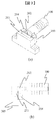
- FIG. 2 is an external view of an example of the ultrasonic cleaner according to the present invention.
- FIG. 2 shows an example in which a diaphragm 202 is used as the vibration part.
- the ultrasonic cleaner 26 of this embodiment can sandwich and fix the BLT 201 that vibrates by applying a periodically changing voltage (for example, sine wave input), the diaphragm 202 to which the BLT 201 is attached, and the diaphragm 202.
- the cleaning port 203, the flange 204, and a sealing material 205 for preventing liquid leakage from between the cleaning port 203 and the diaphragm 202 are configured.
- the peripheral end of the diaphragm 202 is fixed by being pressed by the cleaning port 203 and the flange 204, and the sealing material 205 has a donut shape and is configured to block only the peripheral end of the diaphragm 202.
- the cleaning port 203 has a supply port and a discharge port for a cleaning liquid, which will be described later.
- the cleaning port 203 has an opening 210 (insertion port) for inserting the nozzle 22 at the top, and a large opening is formed on the side surface of the cleaning tank 211 for storing the cleaning liquid. By closing, the cleaning liquid can be stored in the cleaning port 203.
- the vibration generated in the BLT 100 is transmitted to the directly connected diaphragm 202 and is transmitted to the cleaning liquid in the cleaning tank 211 with which the diaphragm 202 is in contact.
- the diaphragm 202 that generates ultrasonic vibrations is provided on the side surface of the cleaning tank 211, and ultrasonic waves can be generated from the lateral direction with respect to the nozzle 22 inserted from the opening 210. it can.
- the opening 210 into which the nozzle 22 is inserted preferably has a shape that allows the nozzle 22 to be inserted as close as possible to the diaphragm 202 (the reason will be described later). Therefore, as shown in FIG. 2A, a part of the opening protrudes toward the diaphragm 202, and this part of the opening 210 and the diaphragm 202 are adjacent to each other through a part of the cleaning port 210. .
- the cleaning port 210 is provided with a notch into which the nozzle 22 is inserted, and the thickness of the cleaning port member is smaller than that of other portions.
- the nozzle 22 can be cleaned close to the diaphragm 202.
- the portion where the cleaning port described above is thin is completely removed, and a part of the opening 210 is in contact with the diaphragm, so that the nozzle 22 can be cleaned closer to the diaphragm 202 and cleaned. it can. That is, a part of the opening 210 of the cleaning port 203 that sandwiches the diaphragm 210 is open, and a part of the peripheral end of the diaphragm is not pressed (free end).
- a cover 220 for protecting the BLT 100 may be attached to the ultrasonic cleaner 26.
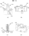
- FIG. 3 is an external view of another example of the ultrasonic cleaner according to the present embodiment.
- a perspective view (a) of the ultrasonic cleaner and a cross-sectional view (b) of the ultrasonic cleaner are respectively shown.
- the ultrasonic cleaner 200 (26 in FIG. 1) differs from the ultrasonic cleaner 26 only in that the cleaning port 203, the flange 204, and the upper portion of the diaphragm 202 are cut off.
- the installation position is the same as that of the ultrasonic cleaner 26.
- the ultrasonic cleaner 200 sandwiches and fixes the diaphragm 202 whose upper portion is cut between the cleaning port 203 and the flange 204, but one side of the upper portion is not restricted and becomes a free end.
- the diaphragm 202 has a configuration in which the amount of deformation at the center portion is large. However, the amount of deformation also increases in the vicinity of the diaphragm 202 in the diaphragm 202 of the ultrasonic cleaner 200. However, since one side of the diaphragm 202 is a free end, the deformation amount near the axis (center) of the diaphragm 202 can be larger than the deformation amount of the diaphragm 202 whose upper portion is not cut. In order to obtain a high cleaning effect, it is preferable to use a diaphragm 202 having at least one free end as in the ultrasonic cleaner 200 of FIG.
- the ultrasonic cleaning device 200 does not show cleaning liquid supply / discharge components (piping connection, tray, etc.), but the cleaning liquid in the cleaning tank 211 overflows with the pressure of the syringe pump as in the ultrasonic cleaning device 26. Then replace. Further, a lid for preventing the cleaning liquid from splashing may be installed on the upper portion of the cleaning tank 211, and a hole into which the nozzle 22 can be inserted may be provided in the lid.
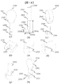
- FIG. 4 shows an example of the ultrasonic vibration means of this embodiment.
- FIG. 4 shows an external view (a), a side view (b) of the diaphragm, and a perspective view (c) of the diaphragm in which the diaphragm of FIG.
- the ultrasonic vibration means of the ultrasonic cleaner 26 of the present invention includes the diaphragm 202 and the BLT 201 described above.
- the BLT 201 sandwiches one or more piezo elements 311 between a metal pressing member (diaphragm side) 312 and a metal pressing member (free end side) 313.
- the holding member 312 and the holding member 313 are threaded.
- the piezo element 311 is hollow, and the piezo element 311 is fixed by fastening the pressing member 312 and the pressing member 313 with bolts (not shown). Since BLT201 is well-known, the detailed description regarding a usage method or a manufacturing method is omitted.
- the diaphragm 202 amplifies the displacement from the screw part 321 for connecting to the BLT 201, the metal plate 322 for propagating the vibration from the BLT 201, the vibration part 323 for propagating the vibration to the cleaning tank, and the BLT 201.
- the connection between the diaphragm 202 and the BLT 201 is fastened by a screw portion (male) 321 of the diaphragm 202 and a screw portion (female) of the metal pressing member 312.
- the metal plate 322 contacts the metal part 312 in order to propagate vibration from the BLT 201.
- the vibrating portion 323 is fixed by sandwiching the peripheral end portion of the vibrating portion 323 between the cleaning port 203 and the flange 204, and the BLT 100 is fixed to the diaphragm 202 in a cantilevered state (the side opposite to the diaphragm 202 is free).
- the diaphragm 202 is fixed at the peripheral end, and the displacement of the one-side free BLT 201 at the center acts on the fixed side of the peripheral end. Therefore, in the example shown in FIG. 4, the deformation amount of the diaphragm 202 increases as the distance from the end of the neck 324 to the fixed side increases. That is, the amount of deformation increases as the neck 324 becomes thinner.
- the configuration is such that the metal portion 312 of the BLT 201 is in direct contact with the vibrating portion 323, the distance from the end of the BLT 201 to the fixed side of the diaphragm 202 is shortened, so that a displacement amount is obtained compared to the configuration shown in FIG. I can't.
- the BLT 201 vibrates by applying a periodically changing voltage to electrodes (not shown) before and after the piezo element 311, a dedicated power amplifier (not shown) is required.
- the ultrasonic cleaner 26 can be driven by a command from a CPU board (not shown) that controls the apparatus to the power amplifier.
- FIG. 5 is a diagram showing standing waves generated when ultrasonic waves are applied to the liquid.
- a standing wave (a) when the frequency of ultrasonic vibration is low and a standing wave (b) when the frequency is high are shown.
- an ultrasonic standing wave 401 is generated in the liquid.
- the wavelength of the standing wave differs depending on the frequency of the ultrasonic vibration, and the wavelength is longer as the frequency is lower. Therefore, the standing wave half wavelength 402 is longer in 402a than in 402b.
- cavitation that is effective for cleaning occurs in a portion where the intensity of the ultrasonic wave is high, and is supersonic in a region 403a near the surface of the ultrasonic vibration unit 400 and a region 404a that is separated from the ultrasonic vibration unit 400 by a half wavelength 402.
- the sound wave intensity increases.
- the distance between the region 403 and the region 404 can be shortened by changing the frequency, the distance cannot be reduced to zero at a frequency (approximately 100 kHz or less) at which cavitation is likely to occur.
- the nozzle 22 is inserted and cleaned from above in FIG. 5 toward the ultrasonic vibration unit 400, cleaning unevenness occurs in a region where cavitation occurs (403 or 404) and a region where it does not occur.
- the ultrasonic intensity is stronger in the region 403 close to the ultrasonic vibration unit 400 and is suitable for cleaning.
- the vibration portion 323 of the diaphragm 202 which is the ultrasonic vibration portion 400, is arranged on the side surface in the cleaning tank, so that the tip of the nozzle 22 can be inserted into a region where the cavitation strength is strong. it can. Accordingly, a wide area on the side surface of the tip of the nozzle 22 can be effectively cleaned.
- FIG. 6 is a diagram showing the relationship between the cleaning liquid and the nozzle position in the ultrasonic cleaner according to the present embodiment.
- a schematic view (a) of the cleaning range and a view (b) showing the positional relationship between the nozzle 22 and the center of the cleaning liquid and diaphragm in the cross section of the cleaning device are shown.
- the nozzle 22 detects the liquid level of the sample so that it is inserted into the sample only up to a limited position at the tip of the nozzle 22, and the position where the nozzle 22 descends is controlled. Has been.
- the liquid level detection and descending control method of the sample in the nozzle 22 will not be described in detail because it is a known technique.
- the range 501 where the sample adheres after the sample is sucked is limited to a certain range. Therefore, if the range 502 to be cleaned by the ultrasonic cleaner 26 is wider than the sample adhesion range 501, it is difficult for unwashed residue to occur.
- the range 503 to be cleaned with water needs to be wider than the range cleaned with the ultrasonic cleaner 26. Become. However, when the water cleaning range 503 is widened, the time required for water cleaning increases. Therefore, it is desirable to set the water cleaning range 503 and the cleaning range 502 as narrow as possible.
- the cleaning liquid is stored in the cleaning tank 211.
- water may be used as the cleaning liquid, it is preferable to use a cleaning liquid capable of removing dirt by chemical action.
- the cleaning liquid has a liquid level from the bottom 511 of the cleaning tank to the tub 512 of the cleaning tank, and the height from the bottom 511 of the cleaning tank to the tub 512 of the cleaning tank is the liquid level 513.
- the diaphragm 202 of the ultrasonic cleaner 26 of the present embodiment has a configuration in which the deformation amount is enlarged at the central portion of the diaphragm, and the ultrasonic intensity in the cleaning liquid is increased near the center of the diaphragm.
- the nozzle tip position 514 is desirably lower than the center line 515. Therefore, when the liquid level 513 of the cleaning liquid is defined as the length 516 from the fixed end of the diaphragm 202 to D, the cleaning range 502 of the nozzle as h, and the liquid level 513 as H, the liquid level of the cleaning liquid is It is preferable to satisfy the following formula. That is, it is desirable to stop and clean the nozzle so as to satisfy Formula 1.
- the liquid level in the washing tank is lower than the position of the center line of the diaphragm plus the length of the washing range of the dispensing nozzle, and the level when the dispensing nozzle is inserted in the washing tank. It is desirable to insert and wash the tip of the nozzle so that it is below the center line of the diaphragm.
- FIG. 7 is a diagram illustrating an example of a piping configuration in the ultrasonic cleaner according to the present embodiment.
- a pipe 601 is connected to the lower part of the cleaning tank 211.
- the pipe 601 includes a syringe pump 602 for extruding the liquid with pressure, a cleaning liquid tank 603 in which the cleaning liquid is stored, a pipe 604 connected to the water supply and supplying water, and switching for switching the connection of the pipe A valve 605 is connected.
- the basket 512 of the cleaning port 203 includes a tray (overflow tray 606) for receiving the overflowing cleaning liquid and a pipe (not shown) connected to the sewer. That is, the upper part of the washing tank has a tray for overflowing the liquid in the washing tank.
- the cleaning tank 211 water or cleaning liquid is always stored, and new liquid is supplied by the pressure of the syringe pump 602.
- the overflowed liquid is discharged to the tray 606, and then the discharged liquid flows into sewage.
- the syringe pump 602 and the switching valve 605 operate in response to an instruction from a CPU board (not shown) that controls the apparatus, supplying cleaning liquid when performing ultrasonic cleaning of the nozzle 22, and supplying water when not cleaning for a long time. Can be supplied and stored.
- the cleaning liquid in the cleaning tank 211 is preferably replaced with all the cleaning liquid after cleaning in order to reduce carryover.
- a new cleaning liquid is supplied to the cleaning tank 211, the cleaning liquid used for cleaning is discharged into sewage by overflow, and the cleaning liquid in the cleaning tank 211 is replaced.
- Can do It is desirable to supply a cleaning liquid only when using ultrasonic cleaning to the cleaning tank, and to supply water and store it in the cleaning tank when not using ultrasonic cleaning. This is because useless consumption of the liquid (cleaning liquid) for cleaning can be suppressed.
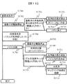
- FIG. 8 is an example of a processing flow of nozzle cleaning using the ultrasonic cleaner of the present invention.
- the sample dispensing mechanism 15 repeats the sampling process S711.
- dispensing (sample aspiration and sample ejection) S712 is performed, and then a cleaning process is performed, and it is determined whether the sample to be dispensed next is the same sample.
- the ultrasonic cleaner 26 performs ultrasonic cleaning (for normal processing) S715 to perform the nozzle 22.
- the sample adhering to is washed, and then the washing liquid is washed away by water washing S716 in the washing tank 27.
- water washing S716 in the washing tank 27.
- the result of the sample determination process S713 is divided into the case of only the water cleaning process S714 and the case of the ultrasonic cleaning S715 and the water cleaning S716, but even if the ultrasonic cleaning process S715 is used every time sampling is performed. good. However, in this case, the amount of cleaning liquid used increases and the cleaning cost increases.
- a maintenance process S721 for cleaning a small amount of dirt accumulated in the nozzle 22 can be executed.
- the operation state S701 it is required to clean in a short time in order not to reduce the throughput of the sampling process, but in the maintenance state S702, the nozzle 22 can be cleaned over time.
- the ultrasonic cleaning (for maintenance) S722 in the maintenance process S721 it is possible to widen the nozzle cleaning range 502 and perform cleaning (that is, deep insertion into the cleaning tank 211).
- the ultrasonic cleaning (for maintenance) S722 is performed using a longer time than the ultrasonic cleaning (for normal use). Thereafter, in a water washing process S723, a wider area than usual is washed away with water.
- the maintenance process S721 is preferably performed periodically.
- the maintenance process S721 can be performed once a day to prevent accumulation of dirt on the nozzle 22.
- the automatic analyzer can control as described above by having parameters in which the cleaning time of the ultrasonic cleaner and the insertion depth of the dispensing nozzle are different between the operation state and the maintenance state.
- an operation of dropping water droplets by vacuum suction after water cleaning may be added.
- FIG. 9 is an external view of an example in which the shape of the cleaning tank of the ultrasonic cleaner of the present invention is changed.
- the cleaning port (a) and the cross-sectional view (b) of the ultrasonic cleaner are respectively shown.
- the ultrasonic cleaner 900 differs from the ultrasonic cleaner 26 only in that the cleaning tank 902 portion of the cleaning port 901 has a conical shape, and the usage method and installation position are the same as the ultrasonic cleaner 26.
- the amount of cleaning liquid to be used can be reduced, and the ultrasonic waves generated from the diaphragm 202 are also generated on the surface 903 of the cleaning port 901 on the cleaning tank side. It is possible to reflect, and the generation of cavitation can be concentrated around the nozzle 22 inserted in the cleaning tank 902, and cleaning can be performed effectively.
- cavitation can be effectively generated in the cleaning range of the nozzle 22 for dispensing the sample, and the nozzle can be effectively cleaned.
- FIG. 10 is an external view of an example of the ultrasonic cleaner according to the present embodiment.
- the present embodiment is an example in which a vibrating unit 222 is used instead of the conventional diaphragm.
- a perspective view (a) of the ultrasonic cleaner, a top view (b) of the ultrasonic cleaner, and a cross-sectional view (c) of the ultrasonic cleaner are shown.
- Cross-sectional view (c) is a cross-sectional view taken along a broken line indicated by A.
- the ultrasonic vibration means of the ultrasonic cleaner 200 (26) of the present invention is the BLT 100.
- the ultrasonic cleaner 200 has a configuration in which the leaf spring 221 and the vibrating portion 222 are fixed to the BLT 100 with bolts 224, and both ends of the leaf spring 221 are fixed to the cleaner base 223.
- the cleaning device base 223 has a cleaning tank 211 that can store the cleaning liquid, and a liquid feeding port 225 that connects a pipe for feeding the cleaning liquid to the cleaning tank 211.
- a cleaning tank 211 that can store the cleaning liquid
- a liquid feeding port 225 that connects a pipe for feeding the cleaning liquid to the cleaning tank 211.
- the vibration of the BLT 100 is transmitted to the vibration unit 222, and the tip (lowermost end) of the vibration unit 222 extends into the cleaning tank 205, and the vibration can be transmitted to the cleaning liquid in the cleaning tank 211.
- the vibration part 222 in the cleaning liquid can generate ultrasonic waves from the side surface of the nozzle 22 by driving the BLT 100.
- the vibration part 222 has a shape extending along the dispensing nozzle, has a first part inserted into the cleaning tank, and the ultrasonic transducer has a second part above the first part. The first part can be vibrated in the horizontal direction.
- the ultrasonic cleaner 200 can replace the cleaning liquid by overflow after cleaning the nozzle 22.
- the vibration part 222 In order to efficiently clean the tip of the nozzle 22, it is desirable to arrange the vibration part 222 so as to be parallel to the nozzle 22, and it is desirable to insert the nozzle near the vibration part 222. Unlike the example of the diaphragm, the nozzle can be inserted at a position close to the vibrating portion 222 without providing the opening 210 with a part protruding. Further, unlike the example of the diaphragm, a high cleaning effect can be obtained without providing a diaphragm or a sealing material for preventing liquid leakage on the side surface of the cleaning tank 211. It is desirable that the leaf spring 221 has a shape that does not twist so that the vibrating portion 222 generates a parallel displacement, and the plate thickness is preferably thin in order to increase the displacement of the vibrating portion 222.
- the vibration unit 222 includes a plate-like member as shown in FIG. 10C and a rod-like member having a certain thickness.
- the shape of the vibrating part 222 is not particularly limited as long as it can be inserted into the cleaning tank 211 and vibrates in the horizontal direction.
- the vibration part 222 may be comprised from multiple members instead of a single member.
- the ultrasonic cleaner 26 generates ultrasonic waves in the cleaning tank.
- the ultrasonic cleaner 26 is inserted into the cleaning liquid in the cleaning tank, and a vibration part for propagating ultrasonic vibration to the cleaning liquid and the piezoelectric element are fastened by fastening two or more metal blocks with bolts.
- an ultrasonic transducer that generates ultrasonic vibrations in the vibration unit.
- the vibrating portion mainly includes a hollow portion 1209.
- FIG. 11 is an external view of an example of an ultrasonic cleaner.
- Each of (a) to (d) is a top view (a), a front view (b), a cross-sectional view (c) (AA cross section of the top view (a)), and a perspective view (d) of the ultrasonic cleaner. It is.
- the ultrasonic cleaner 1200 includes an ultrasonic vibrator 1201, a vibrating part 1202, and a leaf spring 1203.
- the ultrasonic cleaner 1200 has a structure in which a leaf spring 1203 is sandwiched between the ultrasonic vibrator 1201 and the vibration part 1202 and is fixed by a bolt 1204.
- a washer base (made of metal) 1205 that is a part of the automatic analyzer has two columns protruding upward, and both ends of the leaf spring 1203 are fixed to the two columns of the washer base 1205. Yes.
- the tip of the vibration part 1202 is located in the cleaning tank 1206 in the washer base 1205.
- the vibration part 1202 is not in contact with the cleaning tank 1206, and this tip is a free end. That is, the vibration unit 1202 is fixed on a side surface of the metal block 1211 described later and the cleaning tank 1206, and the tip of the vibration unit 1202 to be inserted into the cleaning liquid in the cleaning tank has a free end due to the horizontal vibration of the side surface. Vibrates as.
- the tip of the vibration part 1202 is provided with a cylindrical hole, and the hole penetrates to the bottom of the vibration part 1202 (see FIGS. (A) and (c)). For this reason, the vibration part 202 has the hollow part 1209, and the nozzle 22 can be inserted into the hollow part 1209, and the hollow part 1209 is filled with the cleaning liquid.
- the cleaning tank 1206 can be supplied with cleaning liquid and water from the supply port 1207. By supplying a certain amount or more of liquid, the liquid that has entered the cleaning tank 1206 overflows, and from the discharge port 1208 the outside of the ultrasonic cleaner 1200 is discharged. Can be discharged (liquid replacement due to overflow). In addition, the tip of the vibration unit 1202 after supplying the cleaning liquid can be immersed in the cleaning liquid stored in the cleaning tank 1206.
- the nozzle 22 When cleaning the nozzle 22 with the ultrasonic cleaner 1200, the nozzle 22 is inserted into the hollow portion 1209 at the tip of the vibration unit 1202, so that the tip of the nozzle 22 (the area in contact with the sample) is immersed in the cleaning liquid. .
- the ultrasonic transducer 1202 By inputting a sine wave voltage of, for example, 20 kHz or more to the ultrasonic transducer 1201, the ultrasonic transducer 1202 ultrasonically vibrates in the direction of the arrow.
- the tip of the vibrating part 1202 is also ultrasonically vibrated, and cavitation is generated in the cleaning liquid in the hollow part 1209 so that the nozzle 22 can be cleaned strongly.
- cavitation can be generated from different directions with respect to the side surface of the nozzle 22, so that it is possible to clean the range where the tip is desired to be cleaned evenly.
- the tip of the vibration unit 1202 is a free end, the amplitude of the ultrasonic transducer 1201 is amplified at the tip of the vibration unit 1202 and a lot of cavitation can be generated.
- the distance between the vibration surface (inner periphery of the cup; the cylinder is referred to as a cup for convenience) and the nozzle 22 can be made closer to each other, the tip of the nozzle 22 has a higher density than the area to be cleaned. Cavitation can be generated.
- the cleaning power can be adjusted as appropriate by adjusting the vertical length of the vibrating part 1202 or adjusting the diameter of the hollow part 1209. For example, in the former adjustment, the amplitude of the vibration surface can be increased by increasing the length, and in the latter adjustment, the distance between the vibration surface and the nozzle 22 can be reduced by decreasing the diameter. be able to.
- the cleaning liquid in the cleaning tank 1206 is contaminated with the dirt attached to the nozzle 22 by cleaning the nozzle 22, it is desirable to replace the cleaning liquid after cleaning the nozzle 22. However, if the cleaning liquid is replaced every time the nozzle 22 is cleaned, a large amount of cleaning liquid needs to be stocked in the apparatus. Therefore, it is desirable to reduce the amount of cleaning liquid required to clean the nozzle 22.
- the cleaning liquid can be replaced by overflowing the cleaning liquid, and the nozzle 22 can be cleaned if there is a cleaning liquid in the tip cup of the vibration unit 1202. That is, the shape of the cleaning tank 1206 can be reduced in size within a range where the outside of the vibration unit 1202 does not contact, and the amount of cleaning liquid to be used can be reduced by downsizing the cleaning tank 1206.
- the ultrasonic vibrator 1201 of the ultrasonic cleaner 1200 is assumed to be a BLT.
- the BLT sandwiches a piezoelectric element (hereinafter also referred to as a piezoelectric element) 1213 between two metal blocks (1211 and 1212), and an internal bolt (see FIG. Generally, the structure is fastened and fixed by not shown).
- the piezoelectric element is sandwiched between metal blocks having a relatively large mass and is fastened and fixed with bolts, so that the vibration frequency of the piezoelectric element can be lowered on the metal block side.
- the frequency band of the piezoelectric element of the present embodiment is an element that oscillates in a frequency band in which cavitation is relatively unlikely to occur.
- an ultrasonic wave that oscillates in a frequency band (20 kHz to 100 kHz) in which cavitation is likely to occur.
- a scrubber can be constructed.
- the ultrasonic cleaner 1200 is fixed by a cleaner base 1205 via a leaf spring 1203 to a portion where the vibration amplitude of the ultrasonic vibrator 1201 becomes large (vibration antinode).
- the leaf spring 1203 has a shape with high rigidity, the vibration portion 1202 does not have sufficient amplitude, and the cleaning effect of the nozzle 22 is reduced. For this reason, it is desirable that the leaf spring 1203 has a thin plate thickness and a narrow width.
- the ultrasonic cleaner 1200 can be mounted on an automatic analyzer having a limited installation space because the size of the cleaner can be reduced by reducing the distance between the ultrasonic transducer 1201 and the vibration unit 1202.
- the vibration unit 1202 may have a shape in which a part of the nozzle 22 is missing in addition to a shape that covers the entire circumferential direction of the nozzle 22.
- the partially missing position is a position that does not intersect this straight line when a straight line is drawn from the position of the nozzle 22 in the horizontal section in the vibration direction of the vibration unit 1202. It is desirable.
- a part of the nozzle 22 is crossed when a straight line is drawn in a direction perpendicular to the vibration direction of the vibration unit 1202 from the position of the nozzle 22. It is desirable to provide a position where a part is missing at the position to be performed.
- a shape in which the nozzle 22 is sandwiched between parallel plates or the like may be used as a part of which is missing.
- the arrangement of positions where a part is missing is the same. That is, it is desirable to use a flat plate facing the vibration direction of the vibration unit 1202.
- the plane perpendicular to the vibration direction is the plane most contributing to the occurrence of cavitation
- the most efficient cleaning power can be obtained by adopting the shape of the vibrating part 1202 in which the part is arranged at the top.
- the vibrating portion 1202 may have various shapes, and it is only necessary that the portions be arranged in a plurality of directions when viewed from the nozzle 22, and thus the hollow portion 1209 does not necessarily cover the entire circumferential direction of the nozzle 22. It is not a word that only means the inside of the shape. That is, the inside surrounded by a plurality of parts corresponds to the hollow portion 1209 in this specification regardless of the continuity of the parts.
- these parts are vibration parts 1202 having parts facing each other through the hollow part 1209 in view of efficiency rather than simply arranging parts in a plurality of directions. That is, it is desirable that the vibration unit 1202 includes two surfaces that face each other with the hollow portion 1209 interposed therebetween. This is because the shadow area generated on one surface can be eliminated by the other surface.
- “facing” means not only a parallel surface but also a certain degree of inclination between the surfaces. For example, the inclination angle between the surfaces may be 30 °, and it is considered that the surfaces are opposed if the inclination is less than 90 °.
- the two surfaces face each other in the vibration direction of the vibration part. That is, it is desirable that the two surfaces sandwich the hollow portion 1209 and be perpendicular to the vibration direction.
- the vertical surface includes not only a flat surface but also a curved surface as in this embodiment.
- the vibration part 1202 has a shape surrounding the entire periphery of the hollow part 1209, and these two surfaces are inner wall surfaces of this shape.
- an ultrasonic cleaner having a BLT ultrasonic vibrator and a vibrating part having a hollow part is used to generate ultrasonic vibrations in the vibrating part with a dispensing nozzle inserted in the hollow part.
- a dispensing nozzle inserted in the hollow part.
- the dispensing nozzle can be cleaned with higher cleaning power.
- the vibrating portion includes two surfaces facing each other through the hollow portion, cleaning unevenness can be eliminated more efficiently than in the case of two surfaces not facing each other.
- each surface vibrates in the opposite phase around the nozzle. Due to the vibrations in the opposite phase, the cleaning liquid sandwiched therebetween is greatly undulated. By this undulating action, the cleaning liquid contaminated by the nozzle cleaning moves over this surface and moves to the outside of the hollow portion. Thereby, the cleaning liquid which is not contaminated flows from the lower side of the hollow part into the hollow part. Therefore, the reattachment of the contamination source to the nozzle can be suppressed by the action of the flow of the cleaning liquid.
- the vibration part has a shape that surrounds the entire periphery of the hollow part, and by making the two surfaces the inner wall surface of this shape, the vibration part can be manufactured by a simple processing method. For this reason, a high-performance vibrating part can be manufactured at a relatively low cost. As described above, the same applies to a polygonal column, but a cylindrical shape is optimal in terms of processing cost.
- the inside of the cleaning tank has a curved surface shape without irregularities. It is. For this reason, when performing maintenance such as wiping the inside of the cleaning tank, maintenance is easy. Moreover, in this embodiment, since the vibration part can be removed from the ultrasonic transducer, wiping maintenance and replacement of the vibration part can be easily performed.
- Example 3 the configuration that can obtain a high cleaning effect without mainly cleaning unevenness was described.
- the ultrasonic vibrator 1201 when cleaning with ultrasonic waves is repeatedly performed, the ultrasonic vibrator 1201 generates heat (may be 50 degrees or more depending on driving conditions), and heat moves to the vibration unit 1202.
- the vibration unit 1202 becomes as hot as the ultrasonic transducer 1201.
- the cleaning liquid is supplied around the tip of the vibration unit 1202, but since the amount is small, the heat of the vibration unit 202 moves in a short time and further warms the nozzle 22 inserted into the cleaning tank 1206 for cleaning.
- the water temperature in the automatic analyzer is room temperature (around 25 degrees), and the dispensing performance is affected when the difference between the temperature of the nozzle 22 and the room temperature increases. Since the difference between the nozzle 22 and the water temperature may be high or low, it is desirable to reduce the difference between the nozzle 22 and the room temperature. In order to reduce this difference, it is desirable to dissipate heat before the heat from the ultrasonic transducer 1201 moves to the vibrating part.
- the metal leaf spring 1203 is disposed between the ultrasonic transducer 1201 and the vibrating portion 1202, the heat dissipation effect is not completely absent, but it is a thin plate as described above. This heat dissipation effect is relatively small. For this reason, the following embodiment demonstrates the structure for improving the thermal radiation effect. Since the tip shape of the vibration part 1202 is the same as that of the third embodiment, the description of the configuration and effects is omitted.
- FIG. 12 is an external view of an example of an ultrasonic cleaner (only a vibrating portion) having a structure that can obtain a higher heat dissipation effect than that of the third embodiment.
- (A) to (e) are a top view (a), a side view (b), a perspective view (c), and schematic views (d) and (e) of the cleaning unit, respectively.
- the cleaning tank for storing the cleaning liquid is the same as in FIG.
- the ultrasonic cleaner 1300 uses a BLT type ultrasonic transducer 1301, but instead of the leaf spring 1203, a piezo element 1313 and a metal member 1314 between the metal blocks 1311 and 1312.
- the metal member 1314 can be fixed to the ultrasonic transducer base 1302, and the vibration unit 1303 is fixed to the ultrasonic transducer 1301 with a bolt or the like.
- the tip of the vibration unit 1303 is immersed in a cleaning liquid in a cleaning tank 1206 (not shown in FIG. 12), similar to the ultrasonic cleaner 1200.
- the tip of the nozzle 22 can be cleaned by driving the ultrasonic transducer 1301 while the nozzle 22 is inserted into the cleaning tank 1206 and close to the vibrating unit 1303.
- the ultrasonic cleaner 1300 is fixed to the ultrasonic vibrator base (made of metal) 1302 via the metal member 1314 at a portion where the vibration amplitude of the ultrasonic vibrator 1301 does not increase (vibration node).
- the leaf spring 1203 is not necessary, and the amplitude of the vibrating portion 1202 can be sufficiently generated without reducing the plate thickness of the metal member 1314 as the leaf spring 1203.
- the metal member 1314 is adjacent to the piezo element 1313 which is a heat generation source, and heat when the ultrasonic vibrator 1301 is driven moves from the piezo element to the metal member 1314.
- the nozzle 22 is heated through the cleaning liquid when the nozzle 22 is cleaned.
- the metal member 1314 can be thicker (larger in volume) than the leaf spring 1203, the heat capacity is large, and the heat transfer to the vibration unit 1303 can be made smaller than that of the ultrasonic cleaner 1200. Therefore, by providing the metal member 1314 and the ultrasonic transducer base (made of metal) 1302, heat can be efficiently radiated and heat transfer to the vibration unit 1303 can be suppressed.
- the metal member 1314 and the ultrasonic transducer base 1302 are preferably made of materials having higher thermal conductivity than the metal block 1311 and the vibration part 1303. By positively transferring heat to the child base 1302, the heat from the piezo element 1313 becomes difficult to move to the vibrating portion 1303.
- the metal member 1314 is cooled by cooling the ultrasonic transducer base 1302, and heat transfer to the vibration unit 1303 can be suppressed.
- a cooling means there are a method of attaching an air cooling fan to the ultrasonic transducer base 1302, a method of attaching a water cooling tube, and a method of attaching a Peltier element.
- the vibration unit 1303 is used with the tip portion disposed in the cleaning tank 1206 in the same manner as the ultrasonic cleaner 1200, but the tip portion may be a flat shape or a curved surface. 22 cleanings are possible.
- the entire periphery of the nozzle 22 can be effectively cleaned by providing a hollow portion 1320 that surrounds the nozzle 22 at the tip of the vibrating portion 1303 to form a cup shape.
- the ultrasonic cleaning device 1300 is similar to the ultrasonic cleaning device 1200 in the liquid overflow structure. It can correspond to.
- the cup shape can increase the surface area of the surface of the vibrating portion 1303 in contact with the liquid, so that the cooling effect due to the liquid overflow described later can be enhanced.
- FIG. 13 is an external view of an example of an ultrasonic cleaner having a heat dissipation structure (cooling structure) according to this embodiment.
- (A) to (d) are a top view (a), a rear view (b), a cross-sectional view (c) (cross-section AA in the rear view (b)), and a perspective view (d). It is.
- the ultrasonic cleaner 1400 has the same structure as the ultrasonic cleaner 1200, and the difference is that a heat radiation (cooling) tube 1402 is provided in the ultrasonic vibrator 1401.
- a piezoelectric element is sandwiched between two metal blocks and fastened with internal bolts.
- the tube 1402 enters from the side of the ultrasonic transducer 1401, exits from the back, enters the ultrasonic transducer 1401 from the back, and finally exits from the side of the ultrasonic transducer 1401.
- the tube 1402 can be filled with a fluid (for example, water) and can be circulated by a pump (not shown).
- the fluid in the tube 1402 can dissipate (cool) the heat of the piezoelectric element through a cooling means such as a cooler.
- a cooling function of a cool box (a part of the reagent disk 12) for cooling the reagent in the automatic analyzer 10 may be used.
- the heat generated by the piezo element 1213 can be radiated to the outside of the ultrasonic cleaner 1400 by the circulation of the fluid passing through the tube 1402, and the movement of the heat to the vibration unit 1202 is suppressed. be able to.
- the arrangement of the tube 1402 is shown as a configuration that enters from the side of the ultrasonic transducer 1401 and exits once from the back.
- the surface and position of the tube 1402 that enters and exits can be radiated (cooled) even if different from FIG. .
- the flow path may be formed directly in the ultrasonic transducer 1401 without using the tube 1402, and the tube may be connected to the flow path.
- the tube 1402 is preferably made of a material that can withstand the high temperature of the piezo element 1213 and has low rigidity that does not affect the vibration of the ultrasonic transducer 1401.
- the ultrasonic cleaner 1400 also has a liquid overflow structure like the ultrasonic cleaner 1200, it can dissipate heat (cool) by overflowing the liquid described later.
- FIG. 14 is an example of a liquid overflow structure and pipe connection in the ultrasonic cleaner of the present embodiment.
- a pipe 1501 is connected to the lower part of the cleaning tank 1206.
- the pipe 1501 switches the connection between the syringe pump 1502 for extruding the liquid with pressure, the cleaning liquid tank 1503 in which the cleaning liquid is stored, the pipe 1504 connected to the clean water for supplying water from the water supply, and the piping.
- a switching valve 1505 is connected.
- the cleaning liquid or water can be supplied to the cleaning tank 1206 by controlling the syringe pump 1502 and the switching valve 1505. Further, as shown in a liquid flow path 1507 at the time of overflow, by supplying the liquid, the liquid in the cleaning tank 1206 overflows and can be discharged into sewage by overflow.
- the syringe pump 1502 and the switching valve 1505 operate according to instructions from the control unit 28 that controls the apparatus, and can control the number of overflows and the type of liquid (water or cleaning liquid).
- the above liquid overflow occurs when the heat from the ultrasonic vibrator (any of 1201 to 1401) moves to the tip of the vibrating part (1202 or 1303), and the tip of the vibrating part (1202 or 1303). It can be used to radiate heat from the part.
- heat dissipation from the vibration part to the liquid, discharge of the heated liquid, and supply of the liquid at room temperature are repeated (the temperature of the clean water is lower than that of the vibration part heated for normal temperature) ).
- heat can be exhausted from the tip portion of the vibrating portion (1202 or 1303) by repeating overflow several times. Instead of repeating overflow several times, the liquid may continue to overflow for a long time.
- a cleaning liquid can be supplied, and when the nozzle 22 is not cleaned for a long time, water can be supplied and stored.
- the cleaning liquid supplied to the cleaning tank 1206 can be supplied after the stock solution in the cleaning liquid tank 1503 is diluted with water.
- FIG. 15 is an example of a processing flow of nozzle cleaning using the ultrasonic cleaner of the present invention.
- Each of (a) to (c) is a sampling processing flow (a) of a sample including ultrasonic cleaning, a processing flow (b) of ultrasonic cleaning, and a cleaning liquid replacement timing (c).
- the sample dispensing mechanism 15 repeats the sample sampling process S1611.
- dispensing (sample aspiration and sample ejection) S1612 is performed, and when the dispensed sample is a sample that does not require ultrasonic cleaning (judgment process S1613), a water washing S1614 in which the nozzle 22 is washed with water is performed. If the sample requires ultrasonic cleaning (judgment processing S1613), water cleaning is performed after ultrasonic cleaning S1615 (details of the processing flow will be described later). The above processing is repeated.
- the result of the sample determination S1613 is divided into the case of only the water cleaning S1614, the case of the ultrasonic cleaning S1615, and the case of the water cleaning S1616, but the ultrasonic cleaning S1615 may be performed every sampling.
- the driving of the ultrasonic vibrators (1201, 1301, 1401) is started S1621 (for example, a sine wave having a predetermined voltage is applied), the nozzle 22 is inserted into the cleaning tank 1206 S1622, and after a predetermined time has passed, the nozzle 22 is withdrawn from the cleaning tank 1206, and driving of the ultrasonic transducers (1201, 1301, 1401) is stopped S1624. After that, the cleaning liquid in the cleaning tank 1206 used for cleaning overflows and is exchanged S1625.
- the time from nozzle insertion S1622 to nozzle extraction S1623 is short during operation, but it is possible to estimate the degree of contamination from the number of dispensings and control the cleaning time longer.
- the cleaning time may be extended.
- the execution timing of the heat radiation of the vibration part (1202 or 1303) due to the overflow of the liquid described above may be performed at a timing when the time 1631 during which the ultrasonic cleaning S1615 does not operate becomes long.
- the inspection item managed in the automatic analyzer 10 Alternatively, the schedule in which the ultrasonic cleaning S1615 does not operate may be automatically determined based on the sample type, and the heat (1202 or 1303) may be radiated by overflowing the water S1626.
- the temperature detection means will be described later.
- FIG. 16 is a cleaning flow corresponding to the temperature change of the ultrasonic cleaner in the present invention.
- the execution timing of the ultrasonic cleaning 1700 is the same as that of the ultrasonic cleaning S1615.
- the difference between the resonance frequency of the ultrasonic vibrator (1201, 1301, 1401) and the value measured in advance is predetermined. It is checked in step S1702 whether the threshold is exceeded.
- the resonance frequency can be output via a circuit that applies a voltage to the ultrasonic transducer (a circuit that automatically adjusts the frequency to a low impedance and amplifies and outputs the voltage). Therefore, the control unit 28 can know this difference based on the resonance frequency output from this circuit, and can determine the predetermined threshold value.
- the resonance frequency of the ultrasonic vibrator (1201, 1301, 1401) changes depending on the temperature, and when the resonance frequency changes more than a value measured in advance, the ultrasonic vibrator (1201, 1301, 1401). ) Can be determined to be hot.
- the resonance frequencies of the ultrasonic transducers (1201, 1301, 1401) used for comparison are stored in advance, for example, by a pre-operation when the automatic analyzer 10 is activated.
- overflow cooling S1704 is performed by overflowing the above-described liquid. It is desirable to perform sufficient cooling by executing overflow cooling (heat radiation operation) S1704 for a certain time.
- the nozzle 22 is inserted into the cleaning tank 1206 and S1705 is performed. After the nozzle 22 is placed in the cleaning tank 1206 for a certain period of time and subjected to ultrasonic cleaning S706, the nozzle 22 is pulled out of the cleaning tank 1206, S1707, vibrator drive stop S1708, cleaning liquid replacement S1709 are performed, and nozzle temperature check S1710 is performed. Note that there is no problem even if the vibrator drive stop S1708 and the nozzle temperature check S1710 are performed simultaneously.
- Nozzle temperature check S1710 can use temperature measuring means such as a temperature sensor attached to the nozzle.
- a thermocouple can be considered as the temperature sensor.
- an infrared sensor may be used as the temperature sensor, and the temperature of the nozzle can be obtained in a non-contact manner using the infrared sensor.
- the temperature of the nozzle 22 may be estimated indirectly from the temperature of the water that has washed away the nozzle 22.
- Various means are conceivable for detecting (or predicting) the nozzle temperature, and the present invention is not limited to the above means.
- the nozzle transitions to an abnormal state S1711 after cleaning, and the control unit controls the next scheduled sample suction operation. Interrupt.
- the nozzle 22 itself is cooled (heat radiation) by performing the inside / outside washing process S1712 of the nozzle.
- an alarm may be notified to the user such as displaying an abnormality on the operation screen of the automatic analyzer 10.
- the temperature of the nozzle 22 returns to room temperature. If there is no abnormality in the nozzle temperature check S1710, the sampling process (S1611) is continued S1714 as usual after the water cleaning S1713 of the nozzle 22.
- the process S1702 for checking the change in the resonance frequency of the ultrasonic transducer can be replaced with a means for checking with a temperature sensor or the like.
- the ultrasonic cleaner having the above-described configuration, it is difficult to convey the influence of the temperature of the ultrasonic vibrator, which becomes a high temperature, to the nozzle 22 by cleaning the nozzle 22 repeatedly, and the nozzle can be cleaned.
- a water supply system is provided with a tube that passes through a cooler (for example, a reagent cold storage), and after detecting the temperature in the washing tank 1206, By mixing and diluting the washing liquid, it is possible to control to any liquid temperature.
- a change in the temperature of the liquid after being put in the cleaning tank 1206 is estimated from the measured value of the temperature in the cleaning tank 1206, the temperature of the cleaning liquid is controlled to be low in advance, and the temperature is supplied to the room temperature in the cleaning tank 1206. Is possible.
- FIGS. 15 and 16 Note that the processing of FIGS. 15 and 16 and the checking and control of various sensors are performed by the control unit 28.
- Example 4 In addition to the effects of the vibration part of the third embodiment, the following effects are obtained.
- a metal leaf spring disposed between the ultrasonic vibrator and the vibration portion and a cleaning device base including a cleaning tank are fixed, and the heat dissipation portion includes the leaf spring and the cleaning device.
- Base In order to increase the heat dissipation effect, as in the fourth embodiment, the metal member disposed on the side closer to the piezoelectric element than the vibrating portion and the vibrator base are fixed, and the heat radiating portion includes the metal member and the vibrator.
- a base is desirable. This is because the metal member can have a larger heat capacity than the leaf spring.
- a flow path for flowing a fluid is provided in the ultrasonic vibrator, and the heat radiating portion is a flow path. By flowing a fluid through the flow path, the heat of the piezoelectric element can be radiated.
- a pipe for supplying cleaning liquid and water connected to the cleaning tank is provided, and the control unit performs control for supplying the cleaning liquid and water to the cleaning tank through the pipe. It is desirable to perform control to supply water to the cleaning tank at a timing when drive control is not performed, and to discharge the water from the opening of the cleaning tank by overflow. Thereby, the heat at the tip of the vibration part can be efficiently exhausted by the overflow of water. Further, since the water is not the cleaning liquid, the consumption of the cleaning liquid can be reduced and the heat can be exhausted. When the cleaning liquid is a detergent, the effect of reducing the consumption of the cleaning liquid is a great merit in terms of cost.
- a resonance frequency measurement unit that measures the resonance frequency of the ultrasonic transducer is provided, and the control unit controls the dispensing nozzle that was scheduled to be inserted into the cleaning tank according to the resonance frequency measured by the resonance frequency measurement unit. It is desirable to interrupt. Thereby, the heat of the ultrasonic vibrator can be estimated from the resonance frequency, and the nozzle insertion into the heated cleaning liquid can be suppressed.
- the resonance frequency measuring means is, for example, a circuit itself that applies a voltage to the ultrasonic transducer. For example, when the resonance frequency changes more than a value measured in advance, it is determined that the ultrasonic transducer is hot. it can.
- temperature measuring means for measuring the temperature of the dispensing nozzle is provided, and the control unit interrupts the next scheduled control of the sample suction operation according to the temperature measured by the temperature measuring means.
- the temperature measuring means is, for example, a thermocouple or an infrared sensor attached to the nozzle, and detects the temperature of the water that has washed away the nozzle, and indirectly estimates the temperature of the nozzle from the detection value of this sensor. It may be a thing. For example, this interruption is performed when a difference between the temperature sensor and the room temperature is greater than a threshold value. Thereby, the bad influence on the dispensing precision by the heat
- the measuring device is provided with either a resonance frequency measuring unit for measuring the resonance frequency of the ultrasonic transducer or a measuring unit for measuring the temperature of the dispensing nozzle. It is desirable to dissipate the heat of the dispensing nozzle by bringing the washing water into contact with the outside washing water. Thereby, the thermal radiation of the dispensing nozzle can be performed, and the adverse effect on the dispensing accuracy due to the heat of the piezoelectric element can be suppressed.
- the ultrasonic cleaner 26 generates ultrasonic waves in the cleaning tank.
- the ultrasonic cleaner 26 is inserted into the cleaning liquid in the cleaning tank, and a vibration part for propagating ultrasonic vibration to the cleaning liquid and the piezoelectric element are fastened by fastening two or more metal blocks with bolts.
- an ultrasonic transducer that generates ultrasonic vibrations in the vibration unit.
- the driving frequency is in the range of 20 to 100 kHz and the configuration that generates strong cavitation that can clean the nozzle tip (especially the outer periphery) uniformly, the cleaning liquid
- An ultrasonic cleaner capable of increasing the liquid temperature and obtaining a high cleaning effect will be described.
- cleaning using the chemical effect of the cleaning solution and cleaning using physical effects such as cavitation and straight flow. Both are effective for obtaining a powerful cleaning effect. It is required to use.
- the physical effect of cleaning strong cavitation can be generated by generating a large displacement.
- the cleaning chemical effect it is effective to select an appropriate type of cleaning liquid and to control the liquid temperature. In particular, for dirt containing proteins such as blood, a high cleaning effect can be obtained by increasing the liquid temperature.
- FIG. 17 is a diagram showing an example of the configuration of the ultrasonic cleaner of the present invention.
- Each of (a) to (d) is a top view (a), a side view (b), a cross-sectional view (c) (AA cross section of the top view (a)), and a perspective view (d) of the ultrasonic cleaner.
- the ultrasonic cleaner 26 includes an ultrasonic transducer (BLT) 2205 and a vibration unit (cleaning head) 2209.
- the ultrasonic transducer (BLT) 2205 is configured by sandwiching one or more piezoelectric elements 203 between a front mass 2201 and a back mass 2202 and fastening the front mass 2201 and the back mass 2202 with bolts 2204.
- a base unit 2207 which is a part of the automatic analyzer has a cleaning tank 2206 for storing a cleaning liquid and supports the ultrasonic transducer 2205.
- the ultrasonic transducer 2205 includes a flange portion 2208 and is supported by the base portion 2207 through the flange portion 2208. Further, the ultrasonic vibrator 2205 is connected to a vibration part (cleaning head) 2209 extending to the cleaning tank 2206.
- the tip 2210 of the vibration part (cleaning head) 2209 has a cylindrical shape and is inserted into the cleaning liquid, and part or all of the cylindrical shape is immersed. That is, the vibration part (cleaning head) 2209 has a shape surrounding the nozzle like a cylindrical shape. The tip portion 2210 does not contact the cleaning tank 2206. The cylindrical portion of the tip 2210 has a hole that is larger than the outer diameter of the tip of the nozzle 22. For this reason, the vibration part (cleaning head) 2209 has a hollow part (a nozzle insertion port 303 described later), the nozzle 22 can be inserted into the hollow part, and the hollow part is filled with the cleaning liquid.
- the control unit 28 cleans the nozzle 22 by vibrating the vibration unit (cleaning head) with the nozzle 22 inserted in the hollow portion.
- the cleaning tank 2206 has a cleaning liquid supply pipe 2211 for supplying a cleaning liquid, and the cleaning liquid in the cleaning tank 2206 can be replaced with overflow by supplying a certain amount of cleaning liquid.
- the cleaning liquid overflowing from the cleaning tank 2206 flows into the liquid receiver 2212 on the outer periphery of the cleaning tank 2206 and is discharged from the drainage channel 2213.
- the outlet of the cleaning liquid supply pipe 2221 on the side of the cleaning tank 2206 is arranged directly below the bottom of the vibrating portion as shown in the figure. This is because when the cleaning liquid is supplied vigorously, the cleaning liquid can be prevented from jumping out of the cleaning tank by applying the cleaning liquid to the bottom of the vibration unit.
- the cleaning liquid can be supplied into the cleaning tank vigorously while preventing the cleaning liquid from jumping out of the cleaning tank, and the cleaning liquid can be replaced in a short time.
- the upper side of the flange portion 2208 is pressed from above with a member that can be connected to the base portion 2207, so that the entire flange portion 2208 is supported. It is desirable to fix the circumference evenly. Further, an interference member having elasticity such as rubber or silicon may be inserted in a portion where the flange portion 2208 and the base portion are in contact with each other in order to prevent wear or noise of the flange portion 2208 or the base portion 2207.
- the front mass 2201 and the back mass 2202 are metal blocks, and an electrode plate (for example, a copper plate) is sandwiched between the metal blocks (2201 and 2202) and the piezoelectric elements 2203 and between the plurality of piezoelectric elements 2203.
- the ultrasonic vibrator 2205 is driven in the axial direction of the bolt 2204 by applying a sine wave voltage having an arbitrary frequency to the electrode. This is only an example, and one piezoelectric element 2203 may be used.
- the ultrasonic vibrator 2205 may have any number of piezoelectric elements as long as the piezoelectric element has a structure in which two or more metal blocks are fastened and fixed with bolts.
- the amplitude generated by the piezoelectric element 2203 can be amplified by making the shape of the front mass 2201 into a horn shape (a shape in which the diameter is changed between the piezoelectric element 2203 side and the tip side) as shown in the figure.
- a horn shape a shape in which the diameter is changed between the piezoelectric element 2203 side and the tip side
- FIG. 17 shows a conical horn shape
- other shapes are not a problem. That is, the diameter of the metal block to which the vibration part is fixed is continuously reduced toward the vibration part.
- the horn-shaped cross-sectional shape may not be a circle but may be a polygon. In this case, the circumscribed circle or the inscribed circle is continuously reduced in diameter.
- the vibration unit may be fixed with a bolt or the like as long as the vibration unit is integrated with the front mass 2201, or may be formed as one component with the front mass 2201.
- a horn-shaped front mass 2201 has an elongated vibrating portion (cleaning head) 2209 extending to the cleaning tank 2206, and the member extending downward is bent to further expand the vibration of the horn tip.
- cleaning head elongated vibrating portion
- the ultrasonic cleaner 26 having the above configuration drives the piezoelectric element 2203 at a frequency of 20 to 100 kHz (generates ultrasonic vibration), so that the vibration part (cleaning head) 2209 in the cleaning tank 2206 vibrates with a large displacement. (The frequency is the same as the driving frequency), and cavitation occurs around the tip 2210 immersed in the cleaning liquid.
- the piezoelectric element 2203 When cleaning the nozzle 22 with the ultrasonic cleaner 26, the piezoelectric element 2203 is driven at a frequency of 20 to 100 kHz, and the nozzle 22 is cleaned within the cylindrical inner hole (hollow part) of the tip 2210 ( It is inserted so that the area (about 5 mm from the tip of the nozzle) is immersed in the cleaning liquid, and the dirt attached to the outer periphery of the nozzle is removed by cavitation by contacting with the cleaning water for a certain time.
- the ultrasonic cleaner 26 of the present invention can generate strong cavitation due to the displacement expansion effect of the vibration part (cleaning head) 2209.
- the vibration section (cleaning head) 2209 has a resonance point where the vibration section (cleaning head) 2209 inserted into the cleaning tank 2206 resonates when the ultrasonic vibrator 2205 vibrates in the range of 20 to 100 kHz. Have in.
- the control unit 28 cleans the nozzle 22 by vibrating the vibration unit (cleaning head) 2209 at 20 to 100 kHz with the nozzle inserted in the hollow portion. For this reason, the tip 2210 resonates in synchronization with the vibration of the ultrasonic transducer 2205, and the electric energy applied to the ultrasonic transducer 2205 can be efficiently converted into a large amplitude of the tip 2210.
- the nozzle 22 is pulled out and the cleaning liquid is automatically replaced by overflow, so that the next cleaning of the nozzle 22 can be performed with a new cleaning liquid, and carryover can be suppressed.
- the cleaning can be performed if there is a cleaning liquid around the cylindrical hole of the tip portion 2210 and the periphery thereof, the amount of the cleaning liquid used can be reduced.
- a thin nozzle with an outer diameter of 1.0 mm or less can be cleaned even with a liquid volume of 0.5 mL or less, and the size of the cleaning device can be reduced.
- the cleaning liquid is not limited to a detergent but may be water. Even if water is used, a high cleaning effect by cavitation is obtained, and even if it is not a detergent, warm water is also effective against dirt such as protein, and water may be used depending on the target cleaning effect .
- FIG. 18 shows an example of the structure of the vibration part (cleaning head) 2209 of the ultrasonic cleaner 26 of this embodiment.
- the vibration unit is referred to as a cleaning head 2209. Front view (a), side view (b), perspective view (c), other shape examples (d), (e), (f) of the cleaning head 2209 and an example in which the neck is processed (g) ) And a round portion (R portion) between the tip and the base (h).
- the cleaning head 2209 includes a neck 2304 other than the tip.
- the fixed portion 2301 at the top of the cleaning head 2209 has a cylindrical shape (the horn shape of the front mass 2201). In addition, the side may be inclined.)
- a cleaning unit 2302 is provided at the lower end of the cleaning head 2209.
- the cleaning portion 2302 has the above-described cylindrical shape, and a nozzle insertion port (through hole) 2303 corresponding to the hollow portion, which is larger than the outer shape of the nozzle 22 to be cleaned, is inside the cylindrical shape.
- the neck 2304 for enlarging the displacement of the cleaning part 2302, and a reinforcing part 2305 for connecting the neck 2304 to the fixing part 2301 and increasing the strength of the root part. Since the neck 2304 extends in the vertical direction and the nozzle 22 descends in the vertical direction and is inserted into the hollow portion, in order to avoid interference between the neck 2304 and the nozzle 22, the cleaning unit 2302 is horizontal with respect to the neck 2304. (The side is L-shaped as shown).
- the length from the end surface of the neck 2304 to the tip of the cleaning portion 2302 in the horizontal direction is defined as the cleaning portion length 2302a
- the length from the lower end of the reinforcing portion 2305 to the lower end of the cleaning portion 2302 in the vertical direction is defined as the neck length 2304a
- the cleaning unit height 2302 b is defined by the shape of the cleaning unit 2302.
- the cleaning section 2302 Since the cleaning section 2302 is immersed in the cleaning liquid stored in the cleaning tank 2206 as described above, cavitation occurs in the cleaning liquid in the nozzle insertion port 2303 due to the enlarged vibration in the cleaning section 2302 by driving the piezoelectric element 2203.
- the displacement generated in the piezoelectric element 2203 is enlarged by the above-mentioned horn-shaped front mass 2201 and further enlarged by the neck 2304, so that a large displacement vibration is generated in the cleaning unit 2302.
- Cavitation occurs in a region where ultrasonic waves concentrate, and the stronger the ultrasonic intensity, the stronger the cavitation. Therefore, generating a large displacement in a narrow range is effective for generating cavitation.
- the cleaning head 2209 of the present invention can generate a large displacement, and the nozzle insertion port 2303 in accordance with the size of the nozzle 22 is a narrow region in which the hole diameter can be reduced to several millimeters or less, and a vibration generating surface with high cavitation strength. And the entire circumference of the nozzle 22 are close to each other, so that strong cavitation can be irradiated. Cavitation becomes stronger as the nozzle insertion port 2303 is smaller. However, as described above, the nozzle 22 is moved at a high speed, which causes a problem of residual vibration.
- the nozzle insertion port 2303 is a residual generated by the lowering operation of the nozzle 22.
- the cleaning unit 2302 has a resonance point in the range of 20 to 100 kHz when the ultrasonic transducer 2205 vibrates. Since the ultrasonic vibrator 2205 vibrates at 20 to 100 kHz, the structure of the cleaning head 2209 is configured to easily resonate. Due to this resonance effect, strong cavitation can be irradiated in a short time.
- each shape (2302, 2311, 2312, 2313) of the cleaning unit is not limited.
- the cleaning can be performed even if the cleaning parts (2302, 2331, 2312, 2313) are attached with a 90 degree shift from the axial direction of the bolt 2204.
- the nozzle insertion port 2303 of another shape example can be considered as a hollow portion.
- the shape of the cleaning unit 2302 may be a shape having a cut or a shape completely surrounding the nozzle. That is, if the part of the cleaning unit 2302 is arranged in a plurality of directions when viewed from the nozzle 22, it can be considered as a hollow part. By configuring the cleaning unit 2302 to have such a configuration, uneven cleaning can be suppressed.
- the neck 2304 may be provided with a process 2320 for narrowing the neck diameter in order to easily increase the amplitude of the cleaning unit 2302 (to generate a distortion described later).
- the cleaning head 2314 is an example of a structure different from that of the cleaning head 2209.
- the cleaning head 2314 has a fixed portion 2301, a cleaning portion 2302, and a neck 2304 (there is no reinforcing portion 2305), as in the cleaning head 2209.
- the difference from the cleaning unit 2209 is that the connecting portion 2321 is provided between the cleaning unit 2302 and the neck 2304, and the nozzle insertion port 2303 is located at a relatively far position from the neck 2304.
- the advantage of the cleaning head 2314 is that a round portion (R portion) can be provided in the connection portion 2321, and stress generated at a large amplitude of the cleaning portion 2302 can be dispersed. By dispersing the stress, the durability can be increased and the period of use can be extended.
- the cleaning head 2209 having the above-described configuration is attached to the ultrasonic transducer 2205 described above or integrated with the front mass 2201 so that the cleaning head 2209 is inserted into the nozzle insertion port 2303 and immersed in the cleaning liquid. Cavitation generated in the nozzle insertion port 2303 can be effectively applied.
- FIG. 19 is a diagram showing an example of the vibration mode of the cleaning head 2209 and the temperature gradient of the cleaning liquid.
- Each of (a) to (d) is attached with the deformation of the primary vibration mode (a), the deformation of the secondary vibration mode (b), the temperature gradient of the cleaning liquid (c), and (d) the cleaning head (2209, 2314). It is an impedance waveform of an ultrasonic transducer.
- the cleaning head 2209 has the elongated neck 2304, and the vibration of the cleaning unit 2302 at the tip is expanded.
- the resonance frequency of the cleaning head 2209 is determined by the material (Young's modulus) of the cleaning head 2209, the length and cross-sectional shape of the neck 2304, the mass of the cleaning unit 2302, and the like.
- the vibration of the cleaning unit 2302 has a large amplitude.
- the shape in which the mass such as the cleaning unit 2302 is added to the tip has a plurality of resonance frequencies.
- the cleaning head 2209 has deformations such as the primary vibration mode (a) and the secondary vibration mode (b). There is a resonant frequency that occurs. Note that (a) and (b) show an extremely large deformation of the neck 2304 in order to easily understand the difference between the vibration modes.
- the primary vibration mode is a vibration mode in which the cleaning unit 2302 swings greatly in the axial direction of the bolt 2204.
- the secondary vibration mode is a vibration mode in which the cleaning unit 2302 swings in the axial direction of the bolt 2204 and a vibration node (a portion having a small amplitude) is formed in the middle of the cleaning unit 2302 so that the upper part and the lower part swing greatly.
- the amplitude of the cleaning unit 2302 can be obtained and cavitation can be generated, but in the secondary vibration mode, the upper and lower portions of the cleaning unit 2302 vibrate left and right with opposite phases centering on the nodes.
- the primary vibration mode can have a larger amplitude than the secondary vibration mode.
- the neck 2304 In the primary vibration mode, since the cleaning unit 2302 vibrates greatly, the neck 2304 is deformed and distortion occurs.
- the secondary vibration mode since the upper surface and the lower surface of the cleaning unit 2302 move with vibrations having opposite phases, distortion occurs near the joint between the neck 2304 and the cleaning unit 2302. Since the metal material generates heat when distortion occurs, in the primary mode, the portion near the cleaning unit 2302 of the neck 2304 generates heat, and in the secondary mode, the vicinity of the joint of the cleaning unit 2302 generates heat. Since both the heat generations are close to the cleaning tank 2206, the heat of the cleaning head 2209 moves from the cleaning unit 2302 to the cleaning liquid. In particular, since the cleaning unit 2302 is perforated as described above, the contact area with the cleaning liquid is large and heat can be transferred effectively.
- connection portion between the reinforcement 2 portion 305 and the neck 2304 be rounded (R-processed) so as not to cause a sudden change in shape.
- the temperature gradient 2401 of the cleaning liquid in the cleaning tank 2206 rises linearly until a certain time and starts to saturate after a certain time ((c)). reference). Therefore, the rise in liquid temperature from the start of driving to a certain time later can be represented by a linear approximation line 2402. As described above, the liquid temperature is lowered by overflowing the cleaning liquid, but the temperature gradient 2401 can be increased with the same gradient as before the overflow.
- the liquid temperature after a certain time of operation can be predicted.
- the vibration amplitude becomes maximum in the vicinity of the lower portion of the cleaning unit 2302, and a state where the tip of the nozzle 22 can be cleaned most is created.
- the vibration amplitude becomes maximum near the upper part and the lower part of the cleaning unit 2302, so that a high cleaning effect can be obtained by properly using the vibration mode depending on the point to be cleaned by the nozzle 22. Can be obtained. For example, when sucking from a container containing liquid with the nozzle 22, dirt tends to accumulate at the same position as the liquid surface of the nozzle 22 due to the surface tension of the liquid.
- the cleaning head 2209 when the cleaning head 2209 is driven in the secondary vibration mode, the position where the dirt of the nozzle 22 is accumulated (the same position as the liquid surface when the liquid is sucked) is adjusted to the height above the cleaning head 2209. So you can easily remove dirt. That is, not only the tip of the nozzle 22 but also above this can be cleaned with a strong cleaning power.
- FIG. 19D is a diagram in which the horizontal axis represents frequency and the vertical axis represents impedance.
- a resonance point 2410 of the vibration head and a resonance point 2411 of the ultrasonic transducer 2205 (a mode that expands and contracts in the axial direction of the bolt 2042) are shown.
- the cleaning head 2209 (314) has a structure having a resonance point at a driving frequency of 20 to 100 kHz of the ultrasonic transducer 2205, thereby increasing the cleaning power regardless of whether the driving is in the primary vibration mode or the secondary vibration mode. Can do.
- the resonance point 2410 of the cleaning head (the mode in which the tip shakes greatly as shown in FIGS. 19A and 19B) and the resonance point 2411 of the ultrasonic transducer 2205 approach each other.
- the absolute value of the difference is designed to be 10 kHz or less.
- the resonance point 2410 may be a resonance point in the primary vibration mode or a resonance point in the secondary vibration mode.
- the cleaning portion 2209 (2302) has a structure of a cleaning head 2209 (2314) with a weight attached to the tip of the neck for the convenience of forming a hollow portion.
- the resonance point of the primary vibration mode tends to be low frequency. For this reason, when it is desired to use the primary vibration mode, it is necessary to consider the length of the neck and the weight of the weight. If this is not taken into account, the resonance point of the primary vibration mode of the cleaning head is less than 20 kHz.
- the resonance point of the primary vibration mode and the secondary vibration mode can be within the range of 20 to 100 kHz. Since there are various parameters affecting the resonance point as will be described later, attention is paid here to typical neck length and tip weight.
- the ultrasonic cleaning device is driven to set the temperature of the cleaning liquid in the cleaning tank 2206 to a temperature higher than the normal temperature.
- the nozzle 22 is inserted and ultrasonic cleaning is performed.
- the gradient of the rising temperature per unit time is known in advance, the liquid temperature after a certain time can be predicted.
- the neck length 2304a, width (the neck diameter for the cleaning head 2209) and depth (the neck diameter for the cleaning head 2209) are used. Therefore, it is necessary to appropriately design the mass of the cleaning unit 2302 determined by the rigidity of the neck determined by the length, the length 2302a of the cleaning unit, the inner diameter of the nozzle insertion port 2303, and the outer diameter of the cleaning unit 2302.
- the outer diameter of the tip of the nozzle 22 targeted in this embodiment is as thin as 0.5 to 1.5 mm, and the nozzle cleaning port 2303 needs to be designed according to the outer diameter of the nozzle.
- the inner diameter of the nozzle insertion port 2303 is 2.0 to 4.0 mm and the cleaning range is 4.0 mm at the tip of the nozzle 22, the height 2302b of the cleaning unit is 4.0 mm, and the cleaning head 2314 has a thick neck. And a depth of 3.0 to 5.0 mm, a length of 15 to 20 mm, and a length 2302a of the cleaning portion of 7 to 10 mm, so that the resonance point of the secondary vibration mode is approximately 20 to 100 kHz.
- the thickness and depth of the neck described above are replaced with diameters to be 3.0 to 5.0 mm.
- the resonance frequency can be designed in more detail.
- the rigidity of the neck 2304 changes depending on the presence or absence of the R portion 2321 between the cleaning portion 2302 and the neck 2304 and the shape of the round portion (R portion)
- the design condition of the resonance frequency is deviated by about ⁇ 1 mm from the above-described reference dimension.
- the nozzle insertion port 2303 is moved closer to the distal end side of the cleaning unit 2302 is shown.
- the position of the center of gravity is different, so that the resonance frequency slightly shifts. Become.
- the cleaning head (2209, 2314) is designed within a range outside the above-described dimensions.
- the resonance of the secondary vibration mode at 20 to 100 kHz It is possible to design in the same way from the neck rigidity and the ratio of the cleaning part.
- the material of the cleaning head (2209, 2314) is preferably the same as that of the front mass 2201, and SUS or titanium is preferable.
- the resonance point of the secondary vibration mode is not limited to the above numerical range, Since it is possible, the individual numerical value itself in the specific shape is not important, and the secondary vibration mode can be realized with various numerical values.
- the control unit 28 can obtain the effect obtained in the secondary cleaning mode by cleaning the nozzle by vibrating the ultrasonic vibrator at a frequency at which the cleaning head (2209, 2314) vibrates in the secondary vibration mode. it can.
- FIG. 20 is an example of a time chart of nozzle cleaning during operation using the ultrasonic cleaner of the present embodiment.
- a time chart of nozzle operation, ultrasonic vibrator operation, and replacement of the cleaning liquid is shown, and time variation of the temperature of the cleaning liquid is also shown.
- the apparatus since the apparatus operates at a high throughput for sample inspection, it is necessary to clean the nozzle 22 in a short time. For example, the nozzle 22 is cleaned within 3.6 seconds. These operations are controlled by the control unit 28.
- a certain amount of cleaning liquid is pushed out and overflowed (2501).
- the cleaning liquid is pushed out by a pump connected to the cleaning liquid supply pipe 2211.
- the ultrasonic vibrator is driven to generate ultrasonic vibration for the cleaning liquid in the cleaning tank 2206 (2502).
- ultrasonic vibration By generating ultrasonic vibration, cavitation occurs in the cleaning liquid in the cleaning tank 2206 as described above.
- the nozzle 22 is inserted into the cleaning liquid in the cleaning tank 2206 after the generation of ultrasonic waves (2503), and is extracted from the cleaning tank 2206 after a certain period of time (2504).
- the operation of inserting the nozzle 22 into the cleaning liquid in the cleaning tank 2206 (2503) and the operation of extracting from the cleaning liquid (2504) are performed by the vertical movement of the sample dispensing mechanism 15 as described above, and the nozzle 22 performs the cleaning liquid in the cleaning tank 206.
- the time of immersion in the cleaning time is the cleaning time using the ultrasonic cleaner 26.
- the ultrasonic vibration is stopped (2505) and the cleaning liquid overflows (2506) again for the next cleaning, so that the next cleaning can be performed with a new cleaning liquid.
- the dirt of the nozzle 22 dropped by the vessel 26 is discharged from the apparatus as waste water.
- the cleaning liquid replacement timing may be the timing immediately before the next use of the ultrasonic cleaner 26 or may be immediately after the ultrasonic cleaner 26 is used.
- the temperature (2520) of the cleaning liquid in the cleaning tank 2206 changes as illustrated.
- the liquid temperature decreases, and at the timing (2510) when the ultrasonic vibration is started to clean the nozzle 22, the liquid temperature starts increasing at a constant gradient and the ultrasonic vibrator is stopped. Continue to rise until the timing (2513). After this timing, the liquid temperature decreases, and the liquid temperature further decreases by overflowing (2506) the cleaning liquid.
- the ultrasonic cleaner 26 of this embodiment can control the liquid temperature to a temperature suitable for cleaning at the timing of cleaning the nozzle 22.
- the cleaning head 2209 (2314) of the ultrasonic cleaner 26 generates heat at the neck of the cleaning head by vibrating, and the temperature rise of the liquid temperature changes linearly until a certain time.
- the timing (2510) of starting ultrasonic vibration is adjusted by adjusting the interval (time) between the timing (2510) of starting ultrasonic vibration and the timing (2511) of inserting the nozzle 22 into the cleaning liquid in the cleaning tank.
- the temperature of the cleaning liquid in the cleaning tank 206 can be controlled to an arbitrary liquid temperature.
- the liquid temperature at the time of cleaning can be made higher than when operating at the reference timing, and conversely, if the timing (2510) for starting the ultrasonic vibration is made slower, The liquid temperature at the time of cleaning can be lowered as compared with the case of operating at the reference timing. In this way, a temperature change different from the temperature change shown in FIG. 20 can be realized by adjusting the start timing of the ultrasonic vibration.
- the liquid temperature in the cleaning tank 2206 is not limited to an infinitely high temperature.
- the liquid temperature must be within a range that does not affect the accuracy and higher than room temperature (around 25 ° C.) that can improve the cleaning effect. That is, if the timing (2510) at which the ultrasonic vibration is started is merely early, the dispensing accuracy is deteriorated even if the cleaning effect of the nozzle 22 is obtained, and sufficient performance as an analyzer cannot be realized.
- the liquid temperature has a high cleaning effect (for example, 40 ° C. or higher) and the liquid temperature affects the dispensing accuracy (for example, 60 ° C. or higher), the timing (withdrawal) of the nozzle 22 from the cleaning liquid in the cleaning tank 2206 ( If the liquid temperature is 40 ° C. or higher by 2512), the dispensing accuracy is not affected, and if the liquid temperature is 40 ° C. or higher by the timing (2511) when the nozzle 22 is inserted into the cleaning liquid in the cleaning tank 2206, A cleaning effect higher than that of a cleaning solution (around 25 ° C.) is obtained. Therefore, if the liquid temperature at the timing of starting ultrasonic vibration (2510) is, for example, 25 ° C.
- the temperature gradient of the cleaning liquid that has been confirmed in advance is, for example, 3 ° C./second, the liquid temperature after 5 seconds Since the liquid temperature after 12 seconds becomes 61 ° C., the ultrasonic vibrator is driven at least 5 seconds before 2503 when the nozzle 22 is inserted into the cleaning liquid in the cleaning tank to generate ultrasonic vibration. (502).
- the automatic analyzer is a device that operates at a high throughput. Since the cleaning time of the nozzle 22 can be ensured only about several seconds, the liquid temperature is 40 ° C. to 50 ° C. by inserting the nozzle 22 into the cleaning tank (2503). Then, even if the liquid temperature rises during cleaning, it does not exceed 60 ° C., and there is no influence on the dispensing accuracy.
- an operation pattern is set in consideration of all conditions, it is possible to achieve cleaning at a liquid temperature with a high cleaning effect without affecting the dispensing accuracy even with one operation pattern.
- the volume is reduced, it may be difficult to control the liquid temperature during cleaning of the nozzle 22 in one operation pattern due to the influence of the installation environment temperature of the apparatus and machine differences. For this reason, by adjusting the timing at which the nozzle 22 is inserted into the cleaning liquid and the timing at which the ultrasonic vibration is started, it is possible to easily control the liquid temperature during cleaning of the nozzle 22 within a desired range.
- control unit 28 controls the ultrasonic cleaning of the nozzle 22 within a certain range of temperatures higher than normal temperature by controlling the driving timing of the ultrasonic cleaner or the insertion / extraction timing of the nozzle 22 with respect to the cleaning liquid in the cleaning tank. Cleaning can be performed.
- the ultrasonic cleaning device 26 of the present embodiment can obtain a high cleaning effect in a cleaning time of about several seconds, the time for applying ultrasonic vibration is short, and the cleaning liquid overflows and is replaced every time cleaning is performed. Even if the ultrasonic cleaner 26 is repeatedly used, the ultrasonic cleaner 26 itself does not reach a temperature that affects the dispensing accuracy or a high temperature at which the ultrasonic vibrator 2205 fails.
- a method of arranging a temperature sensor (eg, a thermocouple) in the cleaning tank 2206 a method of attaching a temperature sensor (eg, a thermocouple) to the cleaning liquid supply pipe 2211, or an infrared method outside the cleaning tank 2206
- a temperature sensor eg, a thermocouple
- the temperature detection method does not affect the liquid temperature control method during nozzle cleaning.
- the liquid temperature before driving the ultrasonic cleaning device can be detected by a sensor or the like, for example, the driving time of the ultrasonic cleaning device and the temperature of the cleaning liquid typified by a gradient of rising temperature per unit time. If the relationship with the rise is known in advance, liquid temperature control during nozzle cleaning can be easily performed. Since the device itself can grasp how many seconds after the ultrasonic cleaner is driven, the amount of the nozzle that comes into contact with the cleaning liquid can be accurately predicted because the nozzle is in contact with the cleaning liquid. It is.
- the timing of starting the ultrasonic vibration (2510) or the timing of inserting the nozzle into the cleaning liquid in the cleaning tank (2511) the temperature gradient of the cleaning liquid examined in advance, and the ultrasonic cleaner is driven.
- a desired liquid temperature can be obtained at the timing (2511) when the nozzle 22 is inserted into the cleaning liquid in the cleaning tank.
- the timing of the nozzle 22 is controlled in synchronization with other units (other dispensing mechanisms and reaction disks), and the timing adjustment of the nozzle drive may affect the other units. There is a possibility of complicated control. For this reason, it is desirable to control the liquid temperature during cleaning at the timing (2510) at which ultrasonic vibration is started.
- liquid temperature that affects the dispensing accuracy varies depending on the material and volume of the nozzle 22, but the timing adjustment of the present invention can be handled by knowing the affected temperature in advance.
- the operation at the time of operation has been described.
- the temperature of the cleaning liquid is also increased in the reset operation that initializes the state when the apparatus is started up and the automatic maintenance operation that is performed at the end of the analysis or when the apparatus is shut down. Warm and effective cleaning is possible.
- the overflow (2501) for replacing the cleaning liquid and the driving of the ultrasonic vibrator (2502) are alternately performed, or the cleaning liquid is replaced during the driving of the ultrasonic vibrator (2502).
- (2501) it is possible to control the temperature so as not to increase the liquid temperature excessively, and to operate the ultrasonic cleaner 26 for a long time.
- control unit 28 performs ultrasonic cleaning of the nozzle while performing control to overflow the cleaning liquid in the cleaning tank to the outside of the cleaning tank and introduce a new cleaning liquid into the cleaning tank.
- the same cleaning effect can be obtained in a shorter time than alternately.
- the relationship between the ultrasonic cleaner drive time and the temperature rise of the cleaning liquid is stored, and based on this relationship, the ultrasonic cleaner drive timing during operation or By controlling the insertion / extraction timing with respect to the cleaning liquid in the cleaning tank of the nozzle, it is possible to perform ultrasonic cleaning of the nozzle within a certain range of temperature.
- FIG. 21 is a configuration example of the dispensing mechanism of the automatic analyzer of the present invention and the control block of the cleaning device.
- the operation screen of the automatic analyzer 10 includes an apparatus operation / display unit 2600, and includes an analysis execution operation unit 2601 for executing an examination and a cleaning device state display unit 2602 for displaying the state of the ultrasonic cleaner 26.
- a device control unit 2610 (corresponding to the control unit 28) that controls the device receives a command from the device operation / display unit 2600 from the upper communication processing unit 2611, and the device sequence processing unit 2612 dispenses based on the sequence data 2613. Control of the mechanism 15 and the ultrasonic cleaner 26 is executed.
- the dispensing mechanism control unit 2614 moves the nozzle 22 by rotating and vertically moving the dispensing mechanism 15 via the motor control unit 2615 and the motor driving unit 2616.
- the cleaning device control unit 2617 controls the ultrasonic driving unit (piezoelectric element amplifier) 2619 via the ultrasonic control unit 2618 and drives the ultrasonic vibrator 2205 provided in the ultrasonic cleaning device 26 (turns on the ultrasonic wave). / OFF).
- the ultrasonic drive unit 2619 uses the frequency adjustment unit (adjustment circuit) 2620 to change the drive frequency in accordance with the change in the resonance frequency.
- the cleaning control unit 2617 sends an instruction to the pump control unit 2621, and the pump driving unit 2622 drives the pump 2630 connected to the piping of the cleaning liquid supply pipe 2211.
- the pump driving unit 2622 drives the pump 2630 connected to the piping of the cleaning liquid supply pipe 2211.
- the temperature sensor 2640 disposed in the vicinity of the cleaning tank 2206 collects the values recorded by the temperature measurement unit (temperature sensor value recorder) 2623 by the measurement processing unit 2624 and accumulates them in the ultrasonic driving temperature data 2625. Recording information on the relationship between the driving time of the ultrasonic cleaner such as the temperature gradient and the temperature rise of the cleaning liquid is performed.
- the cleaning device controller 2617 can calculate the timing for driving the ultrasonic transducer 2205 based on the ultrasonic driving temperature data 2625 and adjust the timing (2510) for starting the ultrasonic vibration. In addition, when the liquid temperature is higher than the predetermined value, the liquid temperature can be lowered by the overflow of the cleaning liquid using the pump control unit.
- the ultrasonic driving temperature data 2625 also records data during normal operation, the liquid temperature state management unit 2626 determines the abnormal state of the ultrasonic cleaner 26, and displays the abnormality on the cleaner state display unit 2602. be able to.
- the cleaning device control unit 2614 included in the device control unit 2610 performs control to replace the cleaning liquid in the cleaning tank, and the liquid temperature state management unit 2626 included in the device control unit 2610 includes the measurement temperature of the temperature measurement unit 2623.
- the cleaning liquid in the cleaning tank can be replaced. Since there is a cooling effect by replacing the cleaning liquid, it is possible to suppress damage to the apparatus due to heat.
- the liquid temperature state management unit 2626 determines that the temperature measured by the temperature measurement unit 2623 has exceeded the normal range, it may also notify the abnormality of the ultrasonic cleaner.
- the temperature sensor 2640 may be any detection means other than the above-described method as long as it is not a detection unit that inhibits the insertion / extraction operation of the nozzle 22, affects the vibration of the ultrasonic vibrator 2205, or affects the liquid temperature of the cleaning liquid. Detection means may be used.
- FIG. 22 is an example of a cleaning flow using the ultrasonic cleaner of the present embodiment.
- a cleaning liquid replacement operation S 2701
- S 2702 a replacement completion is determined
- the process waits until the liquid level is stabilized (S 2703).
- the temperature of the cleaning liquid in the cleaning tank 2206 is checked for the liquid temperature using any of the above-described detection methods (S2704), and the ultrasonic cleaner driving time such as the temperature gradient of the cleaning liquid checked in advance.
- the time (timing) for starting the driving of the ultrasonic transducer is calculated from the information regarding the relationship between the temperature rise of the cleaning liquid and the cleaning liquid (S2705).
- the first vibration mode of the cleaning head 2209 or the resonance frequency of the second vibration mode is used to drive the ultrasonic transducer 2205 from the neck 2304 of the cleaning head 2209 as described above.
- Heat generation starts and the temperature of the cleaning liquid in the cleaning tank 2206 can be raised.
- the drive start timing (2510) of the ultrasonic transducer 2205 to an appropriate timing in the ultrasonic vibration start check (S2706)
- the temperature of the cleaning liquid in the cleaning tank 2206 is from room temperature before the nozzle insertion process (S2709). Is a high value (temperature at which the cleaning effect is high), and the temperature is below the liquid temperature that does not affect the dispensing until the nozzle extraction process (S2711).
- Data such as a temperature gradient used in the operation operation may be updated every time the ultrasonic cleaner 26 is used, or during a reset operation or a maintenance operation at startup or periodically from S2707 to S2713 (nozzle operations S2709 and S2711). May be obtained by executing the operation of
- the ultrasonic wave during operation can be adjusted by adjusting the timing with a reset operation or a maintenance operation.
- the drive start timing of the vibrator 2205 may be fixed. If the timing is not adjusted at the timing of the reset operation or the maintenance operation, the ultrasonic transducer may be driven at the driving start timing fixed at the time of shipment. In this case, steps S2705, S2707, and S2713 can be omitted.
- the liquid temperature is dispensed before the nozzle 22 is pulled out (S2711) by checking the temperature affecting the dispensing accuracy or driving the ultrasonic vibrator (S2708).
- a process for predicting whether the temperature will affect the accuracy may be added, and a process for lowering the liquid temperature by overflowing the cleaning liquid before driving the ultrasonic transducer (S2708) may be added.
- the ultrasonic cleaner 26 becomes a high temperature and does not reach the liquid temperature that gives the dispensing accuracy by a normal operation, a higher temperature than normal is detected in the cleaning liquid confirmation process (S2704). In such a case, processing such as displaying an error on the operation unit of the apparatus may be added.
- the liquid temperature is set to the room temperature before inserting the nozzle 22 into the cleaning tank 2206.
- the temperature is set to a higher temperature range that does not affect the dispensing accuracy and concentrating cavitation on the tip of the cleaning head 2209, the outer periphery of the nozzle 22 can be cleaned in a short time, and another sample attached to the nozzle 22 is carried over.
- An inspection apparatus with high inspection accuracy can be provided without any problems.
- Some commercially available cleaners that vibrate the bottom of the cleaning tank with a piezoelectric element generate a flow of liquid called a straight flow in the liquid by driving the piezoelectric element at several MHz, which causes cavitation.
- BLT sandwiches a piezoelectric element between two metal blocks and lowers the resonance frequency to 20 to 100 kHz, which is advantageous for amplitude expansion and cavitation generation.
- the ultrasonic cleaners of Examples 1 to 5 horizontal vibration is generated in the cleaning tank by BLT, and the vibration section that vibrates in the horizontal direction is provided on the side surface in the cleaning tank.
- the ultrasonic cleaners of Examples 2 to 5 have a configuration in which the fulcrum of the vibration unit is provided above the cleaning tank and a part thereof is immersed in the cleaning liquid, which is more than the case where the diaphragm of Example 1 is used for the vibration unit. This is advantageous in that a large amplitude can be obtained.
- the sample dispensing of the biochemical automatic analyzer has been described as an example.
- the ultrasonic cleaning device of the present invention is not limited to the reagent dispensing nozzle, the immune automatic analyzer, the dispensing nozzle of the coagulation automatic analyzer, etc.
- the dispensing nozzle of the clinical examination apparatus can be cleaned.
- not only dispensing nozzles, but also nozzles that perform only suction without performing suction and discharge can be washed.
- the material of the nozzle is not particularly limited, but is a metal nozzle, for example.
- the analysis apparatus including the measurement unit that measures the mixed liquid in the reaction cell has been described as an example.
- the analysis method sucks the mixed liquid from the reaction cell or the like.
- the ultrasonic cleaner of the present invention can also be implemented in an analyzer equipped with a measuring unit of the type that measures light in the pipe.
- analysis using voltage measurement of a mixed solution or a sample can be implemented. Therefore, the measurement unit is not limited to photometry.
- An electrolyte measurement device is an example of an analysis device that uses voltage measurement of a sample, and the ultrasonic cleaner of the present invention can be mounted on the electrolyte measurement device.
- the ultrasonic vibrator is driven before the nozzle is inserted into the cleaning liquid in the cleaning tank.
- the ultrasonic vibrator may be driven after the nozzle is put into the cleaning liquid. good.
- the configuration of the ultrasonic cleaner may or may not include a cleaning tank.
- the same shape of the vibration part may be realized by two or more ultrasonic cleaners.
- cost reduction can be achieved by realizing with one ultrasonic cleaner as in the above embodiment.
- the ultrasonic cleaner described in the present embodiment is useful as a single ultrasonic cleaner for cleaning a dispensing nozzle or a nozzle for sucking a liquid without being incorporated in an automatic analyzer.
- the flow shown in FIG. 22 may be applied to the ultrasonic cleaner configured as shown in FIGS. 10 to 14, or the flow shown in FIGS. 8, 15, and 16 may be applied to the ultrasonic cleaner configured as shown in FIGS. May be applied.
Abstract
Description
D/2 ≦ H ≦ D/2 + h ・・・(式1)
図7は本実施形態の超音波洗浄器における配管構成の一例を示す図である。超音波洗浄器26に洗浄液や水を供給するため、洗浄槽211の下部には配管601が接続される。配管601には、液を圧力で押し出すためのシリンジポンプ602と、洗浄液が貯水されている洗浄液タンク603と、上水道と接続され水を供給するための配管604と、配管の接続を切り替えるための切り替え弁605が接続される。さらに、洗浄ポート203の淵512には溢れた洗浄液を受けるための受け皿(オーバーフロー用受け皿606)と、下水道に接続する配管(図示せず)とがある。つまり、洗浄槽の上部には洗浄槽内の液体をオーバーフローするための受け皿を有する。 (Equation 1)
D / 2 ≦ H ≦ D / 2 + h (Formula 1)
FIG. 7 is a diagram illustrating an example of a piping configuration in the ultrasonic cleaner according to the present embodiment. In order to supply the cleaning liquid and water to the
11 試薬容器
12 試薬ディスク
13 反応ディスク
14 試薬分注機構
15 サンプル分注機構
21 試薬用ノズル
22 サンプル用ノズル
23 サンプル容器
24 ラック
25 反応セル
26 超音波洗浄器
27 洗浄槽
28 制御部
29 測定部
100 BLT
200 超音波洗浄器
201 BLT
202 ダイアフラム
203 洗浄ポート
204 フランジ
205 シール材
208 排出ポート
210 開口部
211 洗浄槽
220 カバー
221 板ばね
222 振動部
223 洗浄器ベース
224 ボルト
225 送液ポート
226 排出用の穴
311 ピエゾ素子
312 押さえ部材
313 押さえ部材
321 ネジ部
322 金属板
323 振動部
324 首
400 振動部
401 定在波
402 定在波の半波長
403 超音波強度が強い領域(振動部側)
404 超音波強度が強い領域(液面側)
501 サンプルが付着する範囲
502 超音波洗浄器の洗浄範囲
503 水洗浄の洗浄範囲
511 洗浄槽の底
512 洗浄槽の淵
513 液位
514 ノズル先端位置
515 ダイアフラムの中心線
516 ダイアフラムの固定端から固定端までの長さ
601 配管
602 シリンジポンプ
603 洗浄液タンク
604 配管(上水道用)
605 切り替え弁
606 オーバーフロー用受け皿
900 超音波洗浄器
901 洗浄ポート
902 洗浄槽
903 洗浄ポートの洗浄槽側の面
1200 超音波洗浄器
1201 超音波振動子
1202 振動部
1203 板ばね
1204 ボルト
1205 洗浄器ベース
1206 洗浄槽
1207 供給口
1208 排出口
1209 中空部
1211 金属ブロック(振動部側)
1212 金属ブロック
1213 ピエゾ素子(圧電素子)
1300 超音波洗浄器
1301 超音波振動子
1302 振動子ベース
1303 振動部
1311 金属ブロック(振動部側)
1312 金属ブロック
1313 ピエゾ素子(圧電素子)
1314 金属部材
1320 中空部
1400 超音波洗浄器
1401 超音波振動子
1402 チューブ
1403 ボルト(内部にチューブを通す穴)
1501 配管
1502 シリンジポンプ
1503 洗浄液タンク
1504 上水と接続する配管
1505 切り替え弁
1506 下水と接続する配管
1507 オーバーフロー時の液の流路
2201 フロントマス
2202 バックマス
2203 圧電素子
2204 ボルト
2205 超音波振動子
2206 洗浄槽
2207 ベース部
2208 フランジ部
2209 振動部(洗浄ヘッド)
2210 先端部
2211 洗浄液供給管
2212 液受け
2213 排出路
2301 固定部
2302 洗浄部
2303 中空部(ノズル挿入口)
2304 首
2305 補強部
2311 角型ブロック形状
2312 円筒形状
2313 角柱状の孔を開けた形状
2314 洗浄ヘッド
2401 温度勾配
2402 線形近似線
2501 オーバーフロー動作
2502 超音波振動子の駆動動作
2503 ノズルを洗浄槽内の洗浄液に挿入する動作
2504 ノズルを洗浄槽内の洗浄液から引き抜く動作
2505 超音波振動子の駆動の停止動作
2506 オーバーフロー動作
2510 超音波振動子の駆動開始タイミング
2511 ノズルを洗浄槽内の洗浄液に挿入するタイミング
2512 ノズルを洗浄槽内の洗浄液から引き抜くタイミング
2513 超音波振動子を停止するタイミング
2520 洗浄液の温度
2600 装置操作・表示部
2601 分析実行操作部
2602 洗浄器状態表示部
2610 装置制御部
2611 上位通信処理部
2612 装置シーケンス処理部
2613 シーケンスデータ
2614 分注機構制御部
2615 モータ制御部
2616 モータ駆動部
2617 洗浄器制御部
2618 超音波制御部
2619 超音波駆動部
2620 周波数調整部
2621 ポンプ制御部
2622 ポンプ駆動部
2623 温度計測部
2624 計測処理部
2625 超音波駆動時温度データ
2626 液温状態管理部
2630 ポンプ
2640 温度センサ DESCRIPTION OF
200 Ultrasonic cleaner 201 BLT
202
404 Ultrasonic intensity region (liquid level side)
501 Range where sample adheres 502 Cleaning range of
605
1212
1300 Ultrasonic cleaner 1301
1312
1314
1501
2210
2304
Claims (41)
- 試料又は試薬を吸引するノズルと、
前記ノズルを洗浄する洗浄槽と、
超音波を発生させる超音波洗浄器と、
前記超音波洗浄器の駆動制御を行う制御部と、を備え、
前記超音波洗浄器は、
前記洗浄槽内の洗浄液に挿入され、超音波振動を洗浄液に伝搬させる振動部と、
圧電素子を2つ以上の金属ブロックをボルトで締結して固定した構成であり、かつ、前記振動部に超音波振動を発生させる超音波振動子と、を備え、
前記制御部は、前記振動部に超音波振動を発生させることにより、前記ノズルの洗浄を行うことを特徴とする自動分析装置。 A nozzle for aspirating the sample or reagent;
A washing tank for washing the nozzle;
An ultrasonic cleaner for generating ultrasonic waves;
A control unit that performs drive control of the ultrasonic cleaner,
The ultrasonic cleaner is
A vibration unit that is inserted into the cleaning liquid in the cleaning tank and propagates ultrasonic vibration to the cleaning liquid;
A piezoelectric element having a structure in which two or more metal blocks are fastened and fixed with bolts, and an ultrasonic vibrator that generates ultrasonic vibrations in the vibration part, and
The automatic analysis apparatus characterized in that the control unit cleans the nozzle by generating ultrasonic vibration in the vibration unit. - 請求項1記載の自動分析装置において、
前記振動部は、前記ノズルを挿入する中空部を有し、
前記制御部は、前記中空部に前記ノズルを挿入した状態で前記振動部に超音波振動を発生させることにより、前記ノズルの洗浄を行うことを特徴とする自動分析装置。 The automatic analyzer according to claim 1, wherein
The vibrating part has a hollow part for inserting the nozzle,
The automatic analysis apparatus, wherein the control unit cleans the nozzles by generating ultrasonic vibrations in the vibration unit in a state where the nozzles are inserted into the hollow part. - 請求項2記載の自動分析装置において、
前記振動部は、前記中空部を介して対向する2つの面を備えることを特徴とする自動分析装置。 The automatic analyzer according to claim 2,
The automatic analyzer is characterized in that the vibration part includes two surfaces facing each other through the hollow part. - 請求項3記載の自動分析装置において、
前記振動部の前記2つの面は前記振動部の振動方向で対向することを特徴とする自動分析装置。 The automatic analyzer according to claim 3,
2. The automatic analyzer according to claim 2, wherein the two surfaces of the vibration part face each other in the vibration direction of the vibration part. - 請求項4記載の自動分析装置において、
前記振動部は前記中空部の周囲を全て囲む形状を有し、前記2つの面は前記形状の内壁面であることを特徴とする自動分析装置。 The automatic analyzer according to claim 4,
2. The automatic analyzer according to claim 1, wherein the vibration part has a shape surrounding the entire periphery of the hollow part, and the two surfaces are inner wall surfaces of the shape. - 請求項1記載の自動分析装置において、
前記振動部は、前記金属ブロックの側面と前記洗浄槽の上方で固定され、
前記洗浄槽内の洗浄液に挿入させる前記振動部の先端は、前記側面の水平方向の振動に伴い自由端として振動することを特徴とする自動分析装置。 The automatic analyzer according to claim 1, wherein
The vibrating part is fixed above the side surface of the metal block and the cleaning tank,
The automatic analyzer is characterized in that the tip of the vibrating part inserted into the cleaning liquid in the cleaning tank vibrates as a free end with the horizontal vibration of the side surface. - 請求項1記載の自動分析装置において、
さらに、前記圧電素子と前記振動部の間に放熱部を備えることを特徴とする自動分析装置。 The automatic analyzer according to claim 1, wherein
Furthermore, an automatic analyzer comprising a heat radiating portion between the piezoelectric element and the vibrating portion. - 請求項7記載の自動分析装置において、
さらに、前記超音波振動子と前記振動部の間に配置された金属製の板ばねと、前記洗浄槽を含む洗浄器ベースとが固定され、前記放熱部は、前記板ばね及び前記洗浄器ベースであることを特徴とする自動分析装置。 The automatic analyzer according to claim 7,
Further, a metal leaf spring disposed between the ultrasonic vibrator and the vibration portion and a washer base including the washing tank are fixed, and the heat radiating portion includes the leaf spring and the washer base. The automatic analyzer characterized by being. - 請求項7記載の自動分析装置において、
さらに、前記振動部よりも前記圧電素子に近い側に配置された金属部材と、振動子ベースとが固定され、前記放熱部は、前記金属部材及び前記振動子ベースであることを特徴とする自動分析装置。 The automatic analyzer according to claim 7,
Furthermore, a metal member disposed closer to the piezoelectric element than the vibration part and a vibrator base are fixed, and the heat dissipation part is the metal member and the vibrator base. Analysis equipment. - 請求項7記載の自動分析装置において、
さらに、前記超音波振動子内に流体を流すための流路を備え、
前記放熱部は、前記流路であることを特徴とする自動分析装置。 The automatic analyzer according to claim 7,
Furthermore, a flow path for flowing a fluid in the ultrasonic vibrator is provided,
The automatic analyzer is characterized in that the heat radiating section is the flow path. - 請求項1記載の自動分析装置において、
さらに、前記洗浄槽に接続された、洗浄液および水を供給する配管を備え、
前記制御部は、前記配管を介して、前記洗浄槽に洗浄液および水を供給する制御を行い、
前記制御部は、前記超音波洗浄器の駆動制御を行っていないタイミングで、前記洗浄槽に水を供給する制御を行い、前記洗浄槽の開口部から当該水をオーバーフローで排出することを特徴とする自動分析装置。 The automatic analyzer according to claim 1, wherein
Furthermore, a pipe for supplying a cleaning liquid and water connected to the cleaning tank is provided.
The control unit performs control to supply a cleaning liquid and water to the cleaning tank via the pipe,
The control unit performs control to supply water to the cleaning tank at a timing when drive control of the ultrasonic cleaner is not performed, and discharges the water by overflow from the opening of the cleaning tank. Automatic analyzer to do. - 請求項1記載の自動分析装置において、
さらに、前記超音波振動子の共振周波数を測定する共振周波数測定手段を備え、
前記共振周波数測定手段が測定した共振周波数に応じて、前記制御部は、前記洗浄槽へ挿入予定であった前記ノズルの制御を、中断することを特徴とする自動分析装置。 The automatic analyzer according to claim 1, wherein
Furthermore, a resonance frequency measuring means for measuring the resonance frequency of the ultrasonic transducer is provided,
In accordance with the resonance frequency measured by the resonance frequency measuring means, the control unit interrupts the control of the nozzle that was scheduled to be inserted into the cleaning tank. - 請求項1記載の自動分析装置において、
さらに、前記ノズルの温度を測定する温度測定手段を備え、
前記温度測定手段が測定した温度に応じて、前記制御部は、次に予定していた試料吸引動作の制御を、中断することを特徴とする自動分析装置。 The automatic analyzer according to claim 1, wherein
Furthermore, a temperature measuring means for measuring the temperature of the nozzle is provided,
In accordance with the temperature measured by the temperature measuring means, the control unit interrupts the next scheduled sample aspirating operation control. - 請求項1記載の自動分析装置において、
さらに、前記超音波振動子の共振周波数を測定する共振周波数測定手段又は前記ノズルの温度を測定する測定手段のいずれかの測定手段を備え、
前記測定手段の測定結果に応じて、前記ノズルに内洗水と外洗水とを接触させることで前記ノズルの熱を放熱させることを特徴とする自動分析装置。 The automatic analyzer according to claim 1, wherein
Furthermore, it comprises a measuring means either a resonant frequency measuring means for measuring the resonant frequency of the ultrasonic vibrator or a measuring means for measuring the temperature of the nozzle,
An automatic analyzer characterized in that heat of the nozzle is dissipated by bringing the inner washing water and outer washing water into contact with the nozzle according to the measurement result of the measuring means. - 請求項1記載の自動分析装置において、
前記振動部は、前記超音波振動子が振動した際に、洗浄槽内に挿入された前記振動部が共振振動する共振点を20~100kHzの範囲内に有し、
前記制御部は、前記中空部に前記ノズルを挿入した状態で前記振動部を20~100kHzで振動させることにより、前記ノズルの洗浄を行うことを特徴とする自動分析装置。 The automatic analyzer according to claim 1, wherein
The vibration unit has a resonance point within a range of 20 to 100 kHz at which the vibration unit inserted into the cleaning tank resonates when the ultrasonic vibrator vibrates,
The automatic analyzer according to claim 1, wherein the control unit cleans the nozzle by vibrating the vibration unit at 20 to 100 kHz with the nozzle inserted into the hollow portion. - 請求項15記載の自動分析装置において、
前記超音波振動子は共振点を20~100kHzの範囲内に有し、
前記超音波振動子の共振点と前記振動部の共振点との差の絶対値は10kHz以下であることを特徴とする自動分析装置。 The automatic analyzer according to claim 15,
The ultrasonic transducer has a resonance point in a range of 20 to 100 kHz,
The automatic analyzer according to claim 1, wherein an absolute value of a difference between a resonance point of the ultrasonic transducer and a resonance point of the vibration unit is 10 kHz or less. - 請求項16記載の自動分析装置において、
前記振動部は、前記振動部が2次振動モードで共振振動する共振点を20~100kHzの範囲内に有し、
前記制御部は、前記振動部が2次振動モードで振動する周波数で前記超音波振動子を振動させることで、前記ノズルの洗浄を行うことを特徴とする自動分析装置。 The automatic analyzer according to claim 16, wherein
The vibration unit has a resonance point within a range of 20 to 100 kHz where the vibration unit resonates in a secondary vibration mode.
The automatic analysis apparatus, wherein the control unit cleans the nozzle by vibrating the ultrasonic transducer at a frequency at which the vibration unit vibrates in a secondary vibration mode. - 請求項1記載の自動分析装置において、
前記ノズルを前記洗浄槽内の洗浄液に挿入する前に、前記超音波洗浄器を駆動することで前記洗浄槽内の洗浄液の温度を常温よりも高い温度とし、当該常温よりも高い温度の洗浄液に前記ノズルを挿入して超音波洗浄を行うことを特徴とする自動分析装置。 The automatic analyzer according to claim 1, wherein
Before inserting the nozzle into the cleaning liquid in the cleaning tank, the temperature of the cleaning liquid in the cleaning tank is set to a temperature higher than normal temperature by driving the ultrasonic cleaner, and the cleaning liquid having a temperature higher than the normal temperature is used. An automatic analyzer characterized by performing ultrasonic cleaning by inserting the nozzle. - 請求項18記載の自動分析装置において、
前記制御部は、前記ノズルの駆動を制御し、
前記制御部は、前記超音波洗浄器の駆動タイミング若しくは前記ノズルの前記洗浄槽内の洗浄液に対する挿抜タイミングを制御することで、前記常温よりも高い温度のうち一定範囲の温度内で前記ノズルの超音波洗浄を行うことを特徴とする自動分析装置。 The automatic analyzer according to claim 18,
The control unit controls driving of the nozzle;
The control unit controls the drive timing of the ultrasonic cleaner or the insertion / extraction timing of the nozzle with respect to the cleaning liquid in the cleaning tank, so that the nozzle can be controlled within a certain range of temperatures higher than the normal temperature. An automatic analyzer characterized by sonic cleaning. - 請求項19記載の自動分析装置において、
前記制御部は、前記自動分析装置のメンテナンス動作やリセット動作の際に、前記超音波洗浄器の駆動時間と洗浄液の温度上昇との関係を記憶し、前記関係に基づき前記駆動タイミング若しくは前記挿抜タイミングを制御することで、前記一定範囲の温度内で前記ノズルの超音波洗浄を行うことを特徴とする自動分析装置。 The automatic analyzer according to claim 19,
The control unit stores a relationship between a driving time of the ultrasonic cleaner and a temperature rise of the cleaning liquid during a maintenance operation or a reset operation of the automatic analyzer, and the driving timing or the insertion / extraction timing based on the relationship An automatic analyzer that performs ultrasonic cleaning of the nozzle within the temperature within the certain range by controlling the above. - 請求項18記載の自動分析装置において、
前記制御部は、前記洗浄槽内の洗浄液を置換する制御を行い、
さらに、前記洗浄槽内の洗浄液の液温を測定する計測部を備え、
前記制御部は、前記計測部の測定温度が正常範囲を超えたと判断したときに、前記洗浄槽内の洗浄液を置換することを特徴とする自動分析装置。 The automatic analyzer according to claim 18,
The control unit performs control to replace the cleaning liquid in the cleaning tank,
Furthermore, a measuring unit for measuring the temperature of the cleaning liquid in the cleaning tank is provided,
The control unit replaces the cleaning liquid in the cleaning tank when it is determined that the measurement temperature of the measurement unit exceeds a normal range. - 請求項21記載の自動分析装置において、
前記制御部は、前記計測部の測定温度が正常範囲を超えたと判断したときに、前記超音波洗浄器の異常を報知することを特徴とする自動分析装置。 The automatic analyzer according to claim 21,
The control unit is configured to notify an abnormality of the ultrasonic cleaning device when determining that the measurement temperature of the measurement unit exceeds a normal range. - 請求項1記載の自動分析装置において、
前記制御部は、前記洗浄槽内の洗浄液を前記洗浄槽外にオーバーフローさせ、新たな洗浄液を前記洗浄槽内に導入する第1の制御を行い、
前記制御部は、前記第1の制御を行う間に、前記ノズルの超音波洗浄を行うことを特徴とする自動分析装置。 The automatic analyzer according to claim 1, wherein
The control unit performs a first control for causing the cleaning liquid in the cleaning tank to overflow outside the cleaning tank and introducing a new cleaning liquid into the cleaning tank,
The automatic analysis apparatus, wherein the control unit performs ultrasonic cleaning of the nozzle while performing the first control. - 請求項1記載の自動分析装置において、
前記振動部は、前記金属ブロックの1つに固定され、
前記振動部が固定された金属ブロックは、前記振動部に向かって径が連続的に小さくなるホーン形状を備えることを特徴とする自動分析装置。 The automatic analyzer according to claim 1, wherein
The vibrating portion is fixed to one of the metal blocks,
The metal block to which the vibration part is fixed is provided with a horn shape whose diameter continuously decreases toward the vibration part. - 請求項1記載の自動分析装置において、
さらに、試料および試薬との混合液を収容する反応セルを有する反応ディスクと、該混合液を測定する測定部と、を備えることを特徴とする自動分析装置。 The automatic analyzer according to claim 1, wherein
An automatic analyzer comprising: a reaction disk having a reaction cell that contains a mixed solution of a sample and a reagent; and a measuring unit that measures the mixed solution. - 請求項1記載の自動分析装置において、
さらに、前記洗浄槽に洗浄液を供給する管を有し、
前記管の前記洗浄槽側の出口は前記振動部の底の真下に配置されていることを特徴とする自動分析装置。 The automatic analyzer according to claim 1, wherein
And a pipe for supplying a cleaning liquid to the cleaning tank,
The automatic analyzer according to claim 1, wherein an outlet of the tube on the washing tank side is disposed immediately below the bottom of the vibrating part. - 洗浄槽内の洗浄液に挿入され、超音波振動を洗浄液に伝搬させる振動部と、
圧電素子を2つ以上の金属ブロックをボルトで締結して固定した構成であり、かつ、前記振動部に超音波振動を発生させる超音波振動子と、
前記超音波振動子の駆動制御を行う制御部と、を備え、
前記制御部は、前記振動部に超音波振動を発生させることにより、試料又は試薬を吸引するノズルの洗浄を行うことを特徴とする超音波洗浄器。 A vibration part that is inserted into the cleaning liquid in the cleaning tank and propagates ultrasonic vibrations to the cleaning liquid;
An ultrasonic vibrator having a structure in which two or more metal blocks are fastened and fixed by a bolt, and an ultrasonic vibrator that generates ultrasonic vibrations in the vibration portion;
A control unit that performs drive control of the ultrasonic transducer,
The ultrasonic cleaning device, wherein the control section cleans a nozzle for sucking a sample or a reagent by generating ultrasonic vibration in the vibration section. - 請求項27記載の超音波洗浄器において、
前記振動部は、前記ノズルを挿入する中空部を有し、
前記制御部は、前記中空部に前記ノズルを挿入した状態で前記振動部に超音波振動を発生させることにより、前記ノズルの洗浄を行うことを特徴とする超音波洗浄器。 The ultrasonic cleaner according to claim 27, wherein
The vibrating part has a hollow part for inserting the nozzle,
The ultrasonic cleaning device, wherein the control unit cleans the nozzle by generating ultrasonic vibration in the vibration unit in a state where the nozzle is inserted into the hollow portion. - 請求項28記載の超音波洗浄器において、
前記振動部は、前記中空部を介して対向する2つの面を備えることを特徴とする超音波洗浄器。 The ultrasonic cleaner according to claim 28, wherein
The ultrasonic cleaning device, wherein the vibration part includes two surfaces facing each other through the hollow part. - 請求項28記載の超音波洗浄器において、
前記振動部は、前記超音波振動子が振動した際に、洗浄槽内に挿入された前記振動部が共振振動する共振点を20~100kHzの範囲内に有し、
前記制御部は、前記中空部に前記ノズルを挿入した状態で前記振動部を20~100kHzで振動させることにより、前記ノズルの洗浄を行うことを特徴とする超音波洗浄器。 The ultrasonic cleaner according to claim 28, wherein
The vibration unit has a resonance point within a range of 20 to 100 kHz at which the vibration unit inserted into the cleaning tank resonates when the ultrasonic vibrator vibrates,
The ultrasonic cleaning device, wherein the control unit cleans the nozzle by vibrating the vibration unit at 20 to 100 kHz with the nozzle inserted in the hollow portion. - 請求項30記載の超音波洗浄器において、
前記振動部は、前記振動部が2次振動モードで共振振動する共振点を20~100kHzの範囲内に有し、
前記制御部は、前記振動部が2次振動モードで振動する周波数で前記超音波振動子を振動させることで、前記ノズルの洗浄を行うことを特徴とする超音波洗浄器。 The ultrasonic cleaner according to claim 30, wherein
The vibration unit has a resonance point within a range of 20 to 100 kHz where the vibration unit resonates in a secondary vibration mode.
The ultrasonic cleaning device, wherein the control unit cleans the nozzle by vibrating the ultrasonic vibrator at a frequency at which the vibration unit vibrates in a secondary vibration mode. - 請求項28記載の超音波洗浄器において、
前記振動部は、前記金属ブロックの1つに固定され、
前記振動部が固定された金属ブロックは、前記振動部に向かって径が小さくなるホーン形状を備えることを特徴とする超音波洗浄器。 The ultrasonic cleaner according to claim 28, wherein
The vibrating portion is fixed to one of the metal blocks,
The ultrasonic cleaner according to claim 1, wherein the metal block to which the vibration part is fixed has a horn shape whose diameter decreases toward the vibration part. - 上部にノズルの挿入口を有し内部に液体を貯めることが可能な洗浄槽と、
前記洗浄槽内の側面側に設けられた振動部と、
前記振動部に接続された超音波振動子と、を有し、
前記超音波振動子は前記振動部を水平方向に振動させ、
前記ノズルは前記振動部の振動に基づき洗浄されることを特徴とする超音波洗浄器。 A cleaning tank having a nozzle insertion port at the top and capable of storing liquid therein;
A vibrating portion provided on a side surface in the cleaning tank;
An ultrasonic transducer connected to the vibrating section,
The ultrasonic vibrator vibrates the vibration part in a horizontal direction,
The ultrasonic cleaning device according to claim 1, wherein the nozzle is cleaned based on vibration of the vibration unit. - 請求項33記載の超音波洗浄器において、
前記振動部は、前記ノズルに沿って延在する形状であり、前記洗浄槽に挿入される第1部位を有し、
前記超音波振動子は、前記第1部位の上方の第2部位を介して、前記第1部位を水平方向に振動させることを特徴とする超音波洗浄器。 The ultrasonic cleaner according to claim 33,
The vibrating portion has a shape extending along the nozzle, and has a first portion inserted into the cleaning tank,
The ultrasonic cleaning device, wherein the ultrasonic vibrator vibrates the first part in a horizontal direction via a second part above the first part. - 請求項33記載の超音波洗浄器において、
前記振動部は、前記洗浄槽の側面に備えられたダイアフラムであって、
前記洗浄槽の中の液体の液位は前記ダイアフラムの中心線の高さに前記ノズルの洗浄範囲の長さを足し合わせた位置より低く、
前記洗浄槽に前記ノズルを挿入した時の前記ノズルの先端は前記ダイアフラムの中心線以下となるように挿入し洗浄を行なうことを特徴とする超音波洗浄器。 The ultrasonic cleaner according to claim 33,
The vibration unit is a diaphragm provided on a side surface of the cleaning tank,
The liquid level in the cleaning tank is lower than the position of the height of the center line of the diaphragm plus the length of the cleaning range of the nozzle,
An ultrasonic cleaning device, wherein cleaning is performed by inserting the nozzle tip into the cleaning tank so that a tip of the nozzle is below a center line of the diaphragm. - 請求項33記載の超音波洗浄器において、
前記振動部は、前記洗浄槽の側面に備えられ、上部がカットされた形状のダイアフラムであって、
前記カットされたダイアフラムの少なくとも1辺は自由端であることを特徴とする超音波洗浄器。 The ultrasonic cleaner according to claim 33,
The vibrating part is provided on a side surface of the cleaning tank, and is a diaphragm having a shape in which an upper part is cut,
The ultrasonic cleaner according to claim 1, wherein at least one side of the cut diaphragm is a free end. - 請求項33記載の超音波洗浄器において、
前記洗浄槽の液体が貯水される部分を円錐型としたことを特徴とする超音波洗浄器。 The ultrasonic cleaner according to claim 33,
The ultrasonic cleaner according to claim 1, wherein a portion of the cleaning tank in which the liquid is stored has a conical shape. - 請求項33記載の超音波洗浄器は、
前記洗浄槽の下部に洗浄液や水を供給する配管と、前記洗浄槽の上部に洗浄槽内の液体をオーバーフローするための受け皿と、を有し、
液体が前記洗浄槽内に供給されることで洗浄槽内の液体をオーバーフローによって交換することができることを特徴とする超音波洗浄器。 The ultrasonic cleaner according to claim 33,
A pipe for supplying a cleaning liquid and water to the lower part of the cleaning tank, and a tray for overflowing the liquid in the cleaning tank at the upper part of the cleaning tank,
An ultrasonic cleaner, wherein the liquid in the cleaning tank can be replaced by overflow by supplying the liquid into the cleaning tank. - 請求項38記載の超音波洗浄器において、
超音波洗浄を利用するときのみ洗浄するための液体を前記洗浄槽に供給し、超音波洗浄を利用しないときには水を供給し前記洗浄槽内に貯めておくことを特徴とする超音波洗浄器。 The ultrasonic cleaner according to claim 38.
An ultrasonic cleaner, wherein a liquid for cleaning is supplied to the cleaning tank only when ultrasonic cleaning is used, and water is supplied and stored in the cleaning tank when ultrasonic cleaning is not used. - 請求項33記載の超音波洗浄器を備えた自動分析装置において、
オペレーション中は次に扱うサンプルが同一であるかを判断し、
次に扱うサンプルが同一サンプルのときには水洗浄のみを行い、次に扱うサンプルが別サンプルのときには前記超音波洗浄器を使った洗浄と水洗浄を行うことを特徴とする自動分析装置。 In the automatic analyzer provided with the ultrasonic cleaner according to claim 33,
During the operation, determine whether the next sample is the same,
An automatic analyzer which performs only water washing when the next sample to be handled is the same sample, and performs washing and water washing using the ultrasonic cleaner when the next sample to be handled is another sample. - 請求項40記載の自動分析装置において、
オペレーション状態とメンテナンス状態で、前記超音波洗浄器の洗浄時間や前記ノズルの挿入深さが異なるパラメータを有することを特徴とする自動分析装置。 The automatic analyzer according to claim 40,
An automatic analyzer having parameters in which the cleaning time of the ultrasonic cleaner and the insertion depth of the nozzle are different between an operation state and a maintenance state.
Priority Applications (5)
| Application Number | Priority Date | Filing Date | Title |
|---|---|---|---|
| CN201680037102.8A CN107735688B (en) | 2015-06-29 | 2016-06-27 | Ultrasonic cleaner and automatic analyzer using the same |
| JP2017526330A JP6427271B2 (en) | 2015-06-29 | 2016-06-27 | Ultrasonic cleaner and automatic analyzer using the same |
| EP16817848.1A EP3315973B1 (en) | 2015-06-29 | 2016-06-27 | Ultrasonic cleaning device and automatic analysis apparatus using same |
| US15/580,910 US10786835B2 (en) | 2015-06-29 | 2016-06-27 | Ultrasonic cleaner and automatic analyzer using the same |
| US17/004,465 US11389838B2 (en) | 2015-06-29 | 2020-08-27 | Ultrasonic cleaner and automatic analyzer using the same |
Applications Claiming Priority (6)
| Application Number | Priority Date | Filing Date | Title |
|---|---|---|---|
| JP2015129454 | 2015-06-29 | ||
| JP2015-129454 | 2015-06-29 | ||
| JP2015252803 | 2015-12-25 | ||
| JP2015-252803 | 2015-12-25 | ||
| JP2016115823 | 2016-06-10 | ||
| JP2016-115823 | 2016-06-10 |
Related Child Applications (2)
| Application Number | Title | Priority Date | Filing Date |
|---|---|---|---|
| US15/580,910 A-371-Of-International US10786835B2 (en) | 2015-06-29 | 2016-06-27 | Ultrasonic cleaner and automatic analyzer using the same |
| US17/004,465 Division US11389838B2 (en) | 2015-06-29 | 2020-08-27 | Ultrasonic cleaner and automatic analyzer using the same |
Publications (1)
| Publication Number | Publication Date |
|---|---|
| WO2017002740A1 true WO2017002740A1 (en) | 2017-01-05 |
Family
ID=57608731
Family Applications (1)
| Application Number | Title | Priority Date | Filing Date |
|---|---|---|---|
| PCT/JP2016/068941 WO2017002740A1 (en) | 2015-06-29 | 2016-06-27 | Ultrasonic cleaning device and automatic analysis apparatus using same |
Country Status (5)
| Country | Link |
|---|---|
| US (2) | US10786835B2 (en) |
| EP (1) | EP3315973B1 (en) |
| JP (1) | JP6427271B2 (en) |
| CN (2) | CN111896763A (en) |
| WO (1) | WO2017002740A1 (en) |
Cited By (7)
| Publication number | Priority date | Publication date | Assignee | Title |
|---|---|---|---|---|
| WO2018116759A1 (en) * | 2016-12-20 | 2018-06-28 | 株式会社日立ハイテクノロジーズ | Ultrasonic washer and automatic analysis apparatus using same |
| WO2018116705A1 (en) * | 2016-12-20 | 2018-06-28 | 株式会社日立ハイテクノロジーズ | Ultrasonic cleaner and automated analyzer using same |
| WO2018123508A1 (en) * | 2016-12-27 | 2018-07-05 | 株式会社日立ハイテクノロジーズ | Nozzle cleaner and automated analyzer using same |
| WO2020095604A1 (en) | 2018-11-06 | 2020-05-14 | 株式会社日立ハイテクノロジーズ | Automated analyzer |
| CN111895651A (en) * | 2020-06-19 | 2020-11-06 | 青岛海尔新能源电器有限公司 | Vertical water tank and water heater |
| WO2022070454A1 (en) | 2020-09-29 | 2022-04-07 | 株式会社日立ハイテク | Ultrasonic washer and automatic analysis device |
| WO2023032435A1 (en) * | 2021-08-31 | 2023-03-09 | 株式会社日立ハイテク | Ultrasonic cleaning machine, automatic analysis device using same, and method for cleaning dispensing nozzle |
Families Citing this family (12)
| Publication number | Priority date | Publication date | Assignee | Title |
|---|---|---|---|---|
| US10663418B2 (en) * | 2017-02-03 | 2020-05-26 | Texas Instruments Incorporated | Transducer temperature sensing |
| US10406751B2 (en) * | 2017-04-14 | 2019-09-10 | Desktop Metal, Inc. | Automated de-powdering with level based nesting |
| WO2018207395A1 (en) * | 2017-05-12 | 2018-11-15 | 株式会社村田製作所 | Vibration device |
| USD862814S1 (en) * | 2017-08-28 | 2019-10-08 | Yen-Kun Chang | Tableware-cleaning machine |
| KR102557840B1 (en) * | 2018-04-02 | 2023-07-20 | 현대모비스 주식회사 | Parking assistance system and method for improving detection performance of ultrasonic sensor thereof |
| US11420236B2 (en) * | 2018-08-28 | 2022-08-23 | Hitachi High-Tech Corporation | Ultrasonic cleaner and automatic analyzer using the same |
| JP6995090B2 (en) * | 2019-07-11 | 2022-01-14 | 日本電子株式会社 | Automatic analyzer and control method of automated analyzer |
| US11759859B2 (en) | 2019-08-23 | 2023-09-19 | Desktop Metal, Inc. | Techniques for depowdering additively fabricated parts through fluid immersion and related systems and methods |
| CN114544994A (en) * | 2020-11-25 | 2022-05-27 | 深圳迈瑞生物医疗电子股份有限公司 | Sample analysis device and sample analysis method |
| CN114307395A (en) * | 2021-11-11 | 2022-04-12 | 荣成碳纤维科技有限公司 | Efficient cleaning method for special precision filter disc for polyacrylonitrile-based carbon fiber dry-jet wet spinning |
| CN114009363A (en) * | 2021-12-14 | 2022-02-08 | 中博农畜牧科技股份有限公司 | Intelligent constant-temperature constant-liquid-level milk cow trough equipment |
| CN114878846B (en) * | 2022-07-08 | 2022-11-22 | 深圳市帝迈生物技术有限公司 | Blood analyzer and cleaning method thereof |
Citations (6)
| Publication number | Priority date | Publication date | Assignee | Title |
|---|---|---|---|---|
| JPS6042635A (en) * | 1983-08-19 | 1985-03-06 | Toshiba Corp | Device for washing nozzle in analytical equipment of biochemistry |
| JPH01101680U (en) * | 1987-12-28 | 1989-07-07 | ||
| JPH049670A (en) * | 1990-04-27 | 1992-01-14 | Olympus Optical Co Ltd | Analyzing apparatus |
| JP2010025587A (en) * | 2008-07-15 | 2010-02-04 | Olympus Corp | Autoanalyzer, specimen dispensing method and special washing method of specimen dispenser |
| JP2010286243A (en) * | 2009-06-09 | 2010-12-24 | Hitachi High-Technologies Corp | Automatic analyzer |
| JP2012150023A (en) * | 2011-01-20 | 2012-08-09 | Hitachi High-Technologies Corp | Autoanalyzer |
Family Cites Families (18)
| Publication number | Priority date | Publication date | Assignee | Title |
|---|---|---|---|---|
| US4516437A (en) * | 1983-03-23 | 1985-05-14 | Coulter Corporation | Microsample handling apparatus |
| US4865060A (en) * | 1989-01-25 | 1989-09-12 | S & C Co., Ltd. | Ultrasonic cleaning system |
| US4989623A (en) * | 1989-12-01 | 1991-02-05 | Akzo N.V. | Apparatus and method for cleaning reagent delivery probes |
| JP2945746B2 (en) * | 1990-11-02 | 1999-09-06 | オリンパス光学工業株式会社 | Biochemical analyzer |
| JPH07243949A (en) * | 1994-03-03 | 1995-09-19 | Olympus Optical Co Ltd | Dispensing nozzle washing device for medical analyzer |
| US5603342A (en) * | 1995-06-29 | 1997-02-18 | Coulter Corporation | Apparatus for cleaning a fluid sample probe |
| DE19610607A1 (en) * | 1996-03-18 | 1997-09-25 | Boehringer Mannheim Gmbh | Device for cleaning pipetting needles or stirrers |
| US6617760B1 (en) * | 1999-03-05 | 2003-09-09 | Cybersonics, Inc. | Ultrasonic resonator |
| CN100443036C (en) * | 2003-02-25 | 2008-12-17 | 松下电工株式会社 | Ultrasonic washing device |
| CN2652535Y (en) * | 2003-09-24 | 2004-11-03 | 张逸夫 | Hand held supersonic cleaning device |
| US7621282B2 (en) * | 2004-06-17 | 2009-11-24 | Abbott Laboratories, Inc. | Probe washing cups and methods |
| JP4519541B2 (en) * | 2004-06-24 | 2010-08-04 | 株式会社東芝 | Ultrasonic cleaning equipment |
| US20060054190A1 (en) * | 2004-09-14 | 2006-03-16 | Bti Holding, Inc. | Plate washing system with ultrasonic cleaning of pipes |
| US20060179946A1 (en) * | 2005-02-01 | 2006-08-17 | Beckman Coulter, Inc. | Method and apparatus for washing a probe or the like using ultrasonic energy |
| US20080142037A1 (en) * | 2006-12-19 | 2008-06-19 | Dempski James L | Apparatus and method for cleaning liquid dispensing equipment |
| US7913561B2 (en) * | 2008-02-05 | 2011-03-29 | Olympus Medical Systems Corp. | Ultrasonic wave vibrating apparatus |
| JP2010133727A (en) * | 2008-12-02 | 2010-06-17 | Beckman Coulter Inc | Cleaning mechanism, cleaning method and analyzer |
| JP6331961B2 (en) * | 2014-10-22 | 2018-05-30 | 東京エレクトロン株式会社 | Substrate liquid processing equipment |
-
2016
- 2016-06-27 US US15/580,910 patent/US10786835B2/en active Active
- 2016-06-27 EP EP16817848.1A patent/EP3315973B1/en active Active
- 2016-06-27 JP JP2017526330A patent/JP6427271B2/en active Active
- 2016-06-27 CN CN202010785176.8A patent/CN111896763A/en active Pending
- 2016-06-27 CN CN201680037102.8A patent/CN107735688B/en active Active
- 2016-06-27 WO PCT/JP2016/068941 patent/WO2017002740A1/en active Application Filing
-
2020
- 2020-08-27 US US17/004,465 patent/US11389838B2/en active Active
Patent Citations (6)
| Publication number | Priority date | Publication date | Assignee | Title |
|---|---|---|---|---|
| JPS6042635A (en) * | 1983-08-19 | 1985-03-06 | Toshiba Corp | Device for washing nozzle in analytical equipment of biochemistry |
| JPH01101680U (en) * | 1987-12-28 | 1989-07-07 | ||
| JPH049670A (en) * | 1990-04-27 | 1992-01-14 | Olympus Optical Co Ltd | Analyzing apparatus |
| JP2010025587A (en) * | 2008-07-15 | 2010-02-04 | Olympus Corp | Autoanalyzer, specimen dispensing method and special washing method of specimen dispenser |
| JP2010286243A (en) * | 2009-06-09 | 2010-12-24 | Hitachi High-Technologies Corp | Automatic analyzer |
| JP2012150023A (en) * | 2011-01-20 | 2012-08-09 | Hitachi High-Technologies Corp | Autoanalyzer |
Non-Patent Citations (1)
| Title |
|---|
| See also references of EP3315973A4 * |
Cited By (13)
| Publication number | Priority date | Publication date | Assignee | Title |
|---|---|---|---|---|
| US11148178B2 (en) | 2016-12-20 | 2021-10-19 | Hitachi High-Tech Corporation | Ultrasonic cleaner and automatic analyzer using the same |
| WO2018116705A1 (en) * | 2016-12-20 | 2018-06-28 | 株式会社日立ハイテクノロジーズ | Ultrasonic cleaner and automated analyzer using same |
| WO2018116759A1 (en) * | 2016-12-20 | 2018-06-28 | 株式会社日立ハイテクノロジーズ | Ultrasonic washer and automatic analysis apparatus using same |
| US11260430B2 (en) | 2016-12-20 | 2022-03-01 | Hitachi High-Tech Corporation | Ultrasonic cleaner and automatic analyzer using the same |
| WO2018123508A1 (en) * | 2016-12-27 | 2018-07-05 | 株式会社日立ハイテクノロジーズ | Nozzle cleaner and automated analyzer using same |
| WO2020095604A1 (en) | 2018-11-06 | 2020-05-14 | 株式会社日立ハイテクノロジーズ | Automated analyzer |
| CN112840215A (en) * | 2018-11-06 | 2021-05-25 | 株式会社日立高新技术 | Automatic analyzer |
| EP3879275A4 (en) * | 2018-11-06 | 2022-08-10 | Hitachi High-Tech Corporation | Automated analyzer |
| CN111895651A (en) * | 2020-06-19 | 2020-11-06 | 青岛海尔新能源电器有限公司 | Vertical water tank and water heater |
| CN111895651B (en) * | 2020-06-19 | 2022-09-13 | 青岛海尔新能源电器有限公司 | Vertical water tank and water heater |
| WO2022070454A1 (en) | 2020-09-29 | 2022-04-07 | 株式会社日立ハイテク | Ultrasonic washer and automatic analysis device |
| JP7441153B2 (en) | 2020-09-29 | 2024-02-29 | 株式会社日立ハイテク | Ultrasonic cleaner and automatic analyzer |
| WO2023032435A1 (en) * | 2021-08-31 | 2023-03-09 | 株式会社日立ハイテク | Ultrasonic cleaning machine, automatic analysis device using same, and method for cleaning dispensing nozzle |
Also Published As
| Publication number | Publication date |
|---|---|
| CN107735688A (en) | 2018-02-23 |
| US11389838B2 (en) | 2022-07-19 |
| US20210053094A1 (en) | 2021-02-25 |
| JP6427271B2 (en) | 2018-11-21 |
| US20180161829A1 (en) | 2018-06-14 |
| US10786835B2 (en) | 2020-09-29 |
| CN111896763A (en) | 2020-11-06 |
| EP3315973A1 (en) | 2018-05-02 |
| CN107735688B (en) | 2020-08-28 |
| EP3315973A4 (en) | 2019-03-06 |
| EP3315973B1 (en) | 2023-05-24 |
| JPWO2017002740A1 (en) | 2018-03-01 |
Similar Documents
| Publication | Publication Date | Title |
|---|---|---|
| WO2017002740A1 (en) | Ultrasonic cleaning device and automatic analysis apparatus using same | |
| US7108003B2 (en) | Ultrasonic cleaning apparatus | |
| KR100392242B1 (en) | Wafer cleaning system | |
| US6148833A (en) | Continuous cleaning megasonic tank with reduced duty cycle transducers | |
| EP3564681B1 (en) | Nozzle cleaner and automated analyzer using same | |
| JP7309731B2 (en) | Ultrasonic cleaner and automatic analyzer using the same | |
| JP6731334B2 (en) | Ultrasonic cleaner and automatic analyzer using the same | |
| JP2009031203A (en) | Automatic analyzer | |
| CN102327883B (en) | Megasonic cleaning head and megasonic cleaning system provided with same | |
| JP6975725B2 (en) | Ultrasonic cleaner and automatic analyzer using it | |
| JP7149810B2 (en) | automatic analyzer | |
| WO2022111600A1 (en) | Sample analysis device | |
| JPH04169850A (en) | Biochemical analyzer | |
| WO2023032435A1 (en) | Ultrasonic cleaning machine, automatic analysis device using same, and method for cleaning dispensing nozzle | |
| JPH05180848A (en) | Cleaner for analyzer |
Legal Events
| Date | Code | Title | Description |
|---|---|---|---|
| 121 | Ep: the epo has been informed by wipo that ep was designated in this application |
Ref document number: 16817848 Country of ref document: EP Kind code of ref document: A1 |
|
| DPE1 | Request for preliminary examination filed after expiration of 19th month from priority date (pct application filed from 20040101) | ||
| ENP | Entry into the national phase |
Ref document number: 2017526330 Country of ref document: JP Kind code of ref document: A |
|
| WWE | Wipo information: entry into national phase |
Ref document number: 15580910 Country of ref document: US |
|
| NENP | Non-entry into the national phase |
Ref country code: DE |
|
| WWE | Wipo information: entry into national phase |
Ref document number: 2016817848 Country of ref document: EP |