JP6331961B2 - Substrate liquid processing equipment - Google Patents
Substrate liquid processing equipment Download PDFInfo
- Publication number
- JP6331961B2 JP6331961B2 JP2014214944A JP2014214944A JP6331961B2 JP 6331961 B2 JP6331961 B2 JP 6331961B2 JP 2014214944 A JP2014214944 A JP 2014214944A JP 2014214944 A JP2014214944 A JP 2014214944A JP 6331961 B2 JP6331961 B2 JP 6331961B2
- Authority
- JP
- Japan
- Prior art keywords
- cleaning
- arm
- liquid
- nozzle
- processing
- Prior art date
- Legal status (The legal status is an assumption and is not a legal conclusion. Google has not performed a legal analysis and makes no representation as to the accuracy of the status listed.)
- Active
Links
Images


Classifications
-
- H—ELECTRICITY
- H01—ELECTRIC ELEMENTS
- H01L—SEMICONDUCTOR DEVICES NOT COVERED BY CLASS H10
- H01L21/00—Processes or apparatus adapted for the manufacture or treatment of semiconductor or solid state devices or of parts thereof
- H01L21/67—Apparatus specially adapted for handling semiconductor or electric solid state devices during manufacture or treatment thereof; Apparatus specially adapted for handling wafers during manufacture or treatment of semiconductor or electric solid state devices or components ; Apparatus not specifically provided for elsewhere
- H01L21/67005—Apparatus not specifically provided for elsewhere
- H01L21/67011—Apparatus for manufacture or treatment
- H01L21/67017—Apparatus for fluid treatment
- H01L21/67028—Apparatus for fluid treatment for cleaning followed by drying, rinsing, stripping, blasting or the like
- H01L21/6704—Apparatus for fluid treatment for cleaning followed by drying, rinsing, stripping, blasting or the like for wet cleaning or washing
- H01L21/67051—Apparatus for fluid treatment for cleaning followed by drying, rinsing, stripping, blasting or the like for wet cleaning or washing using mainly spraying means, e.g. nozzles
-
- B—PERFORMING OPERATIONS; TRANSPORTING
- B05—SPRAYING OR ATOMISING IN GENERAL; APPLYING FLUENT MATERIALS TO SURFACES, IN GENERAL
- B05B—SPRAYING APPARATUS; ATOMISING APPARATUS; NOZZLES
- B05B13/00—Machines or plants for applying liquids or other fluent materials to surfaces of objects or other work by spraying, not covered by groups B05B1/00 - B05B11/00
- B05B13/02—Means for supporting work; Arrangement or mounting of spray heads; Adaptation or arrangement of means for feeding work
- B05B13/0221—Means for supporting work; Arrangement or mounting of spray heads; Adaptation or arrangement of means for feeding work characterised by the means for moving or conveying the objects or other work, e.g. conveyor belts
- B05B13/0228—Means for supporting work; Arrangement or mounting of spray heads; Adaptation or arrangement of means for feeding work characterised by the means for moving or conveying the objects or other work, e.g. conveyor belts the movement of the objects being rotative
-
- B—PERFORMING OPERATIONS; TRANSPORTING
- B05—SPRAYING OR ATOMISING IN GENERAL; APPLYING FLUENT MATERIALS TO SURFACES, IN GENERAL
- B05B—SPRAYING APPARATUS; ATOMISING APPARATUS; NOZZLES
- B05B15/00—Details of spraying plant or spraying apparatus not otherwise provided for; Accessories
- B05B15/50—Arrangements for cleaning; Arrangements for preventing deposits, drying-out or blockage; Arrangements for detecting improper discharge caused by the presence of foreign matter
- B05B15/55—Arrangements for cleaning; Arrangements for preventing deposits, drying-out or blockage; Arrangements for detecting improper discharge caused by the presence of foreign matter using cleaning fluids
-
- B—PERFORMING OPERATIONS; TRANSPORTING
- B05—SPRAYING OR ATOMISING IN GENERAL; APPLYING FLUENT MATERIALS TO SURFACES, IN GENERAL
- B05B—SPRAYING APPARATUS; ATOMISING APPARATUS; NOZZLES
- B05B15/00—Details of spraying plant or spraying apparatus not otherwise provided for; Accessories
- B05B15/70—Arrangements for moving spray heads automatically to or from the working position
-
- B—PERFORMING OPERATIONS; TRANSPORTING
- B08—CLEANING
- B08B—CLEANING IN GENERAL; PREVENTION OF FOULING IN GENERAL
- B08B3/00—Cleaning by methods involving the use or presence of liquid or steam
- B08B3/04—Cleaning involving contact with liquid
-
- B—PERFORMING OPERATIONS; TRANSPORTING
- B08—CLEANING
- B08B—CLEANING IN GENERAL; PREVENTION OF FOULING IN GENERAL
- B08B3/00—Cleaning by methods involving the use or presence of liquid or steam
- B08B3/04—Cleaning involving contact with liquid
- B08B3/10—Cleaning involving contact with liquid with additional treatment of the liquid or of the object being cleaned, e.g. by heat, by electricity or by vibration
- B08B3/12—Cleaning involving contact with liquid with additional treatment of the liquid or of the object being cleaned, e.g. by heat, by electricity or by vibration by sonic or ultrasonic vibrations
-
- B—PERFORMING OPERATIONS; TRANSPORTING
- B08—CLEANING
- B08B—CLEANING IN GENERAL; PREVENTION OF FOULING IN GENERAL
- B08B3/00—Cleaning by methods involving the use or presence of liquid or steam
- B08B3/02—Cleaning by the force of jets or sprays
Description
本発明は、基板に処理液を供給する処理液ノズルを保持したノズルアームを清浄に保つ技術に関する。 The present invention relates to a technique for keeping a nozzle arm holding a processing liquid nozzle for supplying a processing liquid to a substrate clean.
基板である半導体ウエハ(以下、ウエハという)に薬液処理、リンス処理などの液処理を施す際には、ノズルアームに保持された処理液ノズルをウエハの上方に位置させて処理液を供給する。しかしながら処理液ノズルから供給された処理液は、ウエハからの跳ね返りなどによってノズルアームに付着することがある。この処理液が乾燥すると、パーティクルの発生原因ともなる。 When liquid processing such as chemical processing or rinsing processing is performed on a semiconductor wafer (hereinafter referred to as a wafer) that is a substrate, the processing liquid nozzle is held above the wafer and the processing liquid is supplied. However, the processing liquid supplied from the processing liquid nozzle may adhere to the nozzle arm due to rebound from the wafer or the like. When this treatment liquid dries, it also causes generation of particles.
ここで特許文献1には、洗浄液を噴出する複数の噴出孔が、ノズルアームの伸びる方向に沿って列設され、ノズルアームに向けて洗浄液を吹き付けて洗浄を行うシャワーノズルが記載されている。しかしながら、噴出孔に対向していないノズルアーム面には洗浄液を供給することが困難であり、洗い残しが発生するおそれがある。 Here, Patent Document 1 describes a shower nozzle in which a plurality of ejection holes for ejecting a cleaning liquid are arranged along a direction in which a nozzle arm extends, and cleaning is performed by spraying the cleaning liquid toward the nozzle arm. However, it is difficult to supply the cleaning liquid to the nozzle arm surface that does not face the ejection hole, and there is a possibility that unwashed residue may occur.
本発明はこのような事情の下になされたものであり、その目的は、ノズルアームを清浄な状態に維持することが可能な基板液処理装置を提供することにある。 The present invention has been made under such circumstances, and an object thereof is to provide a substrate liquid processing apparatus capable of maintaining a nozzle arm in a clean state.
本発明の基板液処理装置は、基板を保持する基板保持部と、
前記基板保持部に保持された基板に処理液を供給する処理液ノズルと、
前記処理液ノズルを保持するノズルアームと、
前記ノズルアームの全面を洗浄液中に浸漬させて洗浄するためのアーム洗浄槽と、を備えたことを特徴とする。
The substrate liquid processing apparatus of the present invention includes a substrate holding unit for holding a substrate,
A processing liquid nozzle for supplying a processing liquid to the substrate held by the substrate holding unit;
A nozzle arm for holding the treatment liquid nozzle ;
The entire surface of the front Symbol nozzle arm, characterized in that and a arm cleaning tank for cleaning is immersed in the cleaning liquid.
前記基板液処理装置は、以下の構成を備えていてもよい。
(a)前記アーム洗浄槽に前記ノズルアームと前記処理液ノズルが同時に収容され、前記洗浄液中に同時に浸漬されること。
(b)前記アーム洗浄槽は、前記洗浄液を供給する洗浄液供給部と、前記アーム洗浄槽の洗浄液を排出する洗浄液排出部と、を備えたこと。このとき、前記ノズルアームを駆動する駆動機構を備え、前記駆動機構はノズルアームの昇降機能を備え、または前記洗浄液供給部はアーム洗浄槽内の洗浄液の液面の高さ位置の調節機能を備え、記洗浄液内にノズルアームを浸漬させて洗浄する洗浄位置と、前記洗浄液に処理液ノズルのみを浸漬させて洗浄する位置との間で、前記ノズルアームの高さ位置または前記液面の高さ位置を制御する制御信号を前記駆動機構または洗浄液供給部に供給する制御部を備えたこと。
(c)前記ノズルアームは、撥水性の部材によって構成されていること。前記アーム洗浄槽に、前記洗浄液よりも揮発性の高い乾燥液を供給する乾燥液供給部を備えていること。前記ノズルアームを駆動する駆動機構を備え、前記駆動機構は、アーム洗浄槽の側方に配置され、前記ノズルアームは、アーム洗浄槽内の洗浄液に浸漬可能なように、前記駆動機構による支持位置の側方で下方へ向けて伸延した縦棒部分と、縦棒部分の下端から横方向へ向けて伸延した横棒部分とを含むこと。
(d)前記アーム洗浄槽には、当該アーム洗浄槽内の洗浄液に超音波振動を印加するための振動部が設けられていること。前記洗浄液の温度調節を行う温度調節部を備えたこと。
(e)前記アーム洗浄槽の内部には、前記処理液ノズルから吐出された処理液を受けて外部へ排出する液受部が設けられていること。または、前記アーム洗浄槽の底部には、前記処理液ノズルから吐出された処理液を受けて外部へ排出する液受部が設けられていること。
(f)前記アーム洗浄槽に連続的に洗浄液を供給する洗浄液供給部と、前記アーム洗浄槽の上端部を周方向に囲むように設けられ、当該アーム洗浄槽からオーバーフローした洗浄液を受け止め、洗浄液を排出するための排出口を備えた排液溝部と、を備えたこと。
(g)前記アーム洗浄槽の下方には、前記アーム洗浄槽から排出された前記洗浄液を受け入れる排出槽を備え、前記排出槽は、アーム洗浄槽内の洗浄液を全量、受け入れることが可能な容量を有すること。
The substrate liquid processing apparatus may have the following configuration.
(A) The nozzle arm and the treatment liquid nozzle are simultaneously accommodated in the arm cleaning tank, and are immersed in the cleaning liquid at the same time.
( B ) The arm cleaning tank includes a cleaning liquid supply unit that supplies the cleaning liquid and a cleaning liquid discharge unit that discharges the cleaning liquid of the arm cleaning tank. At this time, a drive mechanism for driving the nozzle arm is provided, the drive mechanism has a function of raising and lowering the nozzle arm, or the cleaning liquid supply unit has a function of adjusting the height position of the cleaning liquid level in the arm cleaning tank. The height position of the nozzle arm or the height of the liquid surface is between a cleaning position where the nozzle arm is immersed in the cleaning liquid for cleaning, and a position where only the processing liquid nozzle is immersed in the cleaning liquid for cleaning. A control unit for supplying a control signal for controlling the position to the drive mechanism or the cleaning liquid supply unit;
( C ) The nozzle arm is made of a water-repellent member. The arm cleaning tank includes a drying liquid supply unit that supplies a drying liquid having higher volatility than the cleaning liquid. A drive mechanism for driving the nozzle arm, the drive mechanism is disposed on a side of the arm cleaning tank, and the nozzle arm is supported by the driving mechanism so as to be immersed in a cleaning liquid in the arm cleaning tank. A vertical bar portion extending downward on the side of the vertical bar portion, and a horizontal bar portion extending laterally from the lower end of the vertical bar portion .
( D ) The arm cleaning tank is provided with a vibration section for applying ultrasonic vibration to the cleaning liquid in the arm cleaning tank. Further comprising a temperature adjusting unit for adjusting the temperature of the pre Kiarai solution purification.
( E ) A liquid receiving portion for receiving the processing liquid discharged from the processing liquid nozzle and discharging it to the outside is provided inside the arm cleaning tank. Alternatively, a liquid receiving portion for receiving the processing liquid discharged from the processing liquid nozzle and discharging it to the outside is provided at the bottom of the arm cleaning tank.
( F ) A cleaning liquid supply unit that continuously supplies the cleaning liquid to the arm cleaning tank, and an upper end portion of the arm cleaning tank are provided to surround the arm cleaning tank in a circumferential direction. And a drainage groove having a discharge port for discharging.
(G) A discharge tank for receiving the cleaning liquid discharged from the arm cleaning tank is provided below the arm cleaning tank, and the discharge tank has a capacity capable of receiving all the cleaning liquid in the arm cleaning tank. Having.
本発明は、アーム洗浄槽内の洗浄液にノズルアームを浸漬させて洗浄を行うので、ノズルアームの全面を洗浄することができる。 In the present invention, since the nozzle arm is immersed in the cleaning liquid in the arm cleaning tank for cleaning, the entire surface of the nozzle arm can be cleaned.
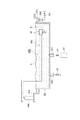
図1は、本実施形態に係る基板処理システムの概略構成を示す図である。以下では、位置関係を明確にするために、互いに直交するX軸、Y軸およびZ軸を規定し、Z軸正方向を鉛直上向き方向とする。 FIG. 1 is a diagram showing a schematic configuration of a substrate processing system according to the present embodiment. In the following, in order to clarify the positional relationship, the X axis, the Y axis, and the Z axis that are orthogonal to each other are defined, and the positive direction of the Z axis is the vertically upward direction.
図1に示すように、基板処理システム1は、搬入出ステーション2と、処理ステーション3とを備える。搬入出ステーション2と処理ステーション3とは隣接して設けられる。
As shown in FIG. 1, the substrate processing system 1 includes a carry-in / out station 2 and a
搬入出ステーション2は、キャリア載置部11と、搬送部12とを備える。キャリア載置部11には、複数枚の基板、本実施形態では半導体ウエハ(以下ウエハW)を水平状態で収容する複数のキャリアCが載置される。
The carry-in / out station 2 includes a
搬送部12は、キャリア載置部11に隣接して設けられ、内部に基板搬送装置13と、受渡部14とを備える。基板搬送装置13は、ウエハWを保持するウエハ保持機構を備える。また、基板搬送装置13は、水平方向および鉛直方向への移動ならびに鉛直軸を中心とする旋回が可能であり、ウエハ保持機構を用いてキャリアCと受渡部14との間でウエハWの搬送を行う。
The
処理ステーション3は、搬送部12に隣接して設けられる。処理ステーション3は、搬送部15と、複数の処理ユニット16とを備える。複数の処理ユニット16は、搬送部15の両側に並べて設けられる。
The
搬送部15は、内部に基板搬送装置17を備える。基板搬送装置17は、ウエハWを保持するウエハ保持機構を備える。また、基板搬送装置17は、水平方向および鉛直方向への移動ならびに鉛直軸を中心とする旋回が可能であり、ウエハ保持機構を用いて受渡部14と処理ユニット16との間でウエハWの搬送を行う。
The
処理ユニット16は、基板搬送装置17によって搬送されるウエハWに対して所定の基板処理を行う。
The
また、基板処理システム1は、制御装置4を備える。制御装置4は、たとえばコンピュータであり、制御部18と記憶部19とを備える。記憶部19には、基板処理システム1において実行される各種の処理を制御するプログラムが格納される。制御部18は、記憶部19に記憶されたプログラムを読み出して実行することによって基板処理システム1の動作を制御する。
Further, the substrate processing system 1 includes a control device 4. The control device 4 is a computer, for example, and includes a
なお、かかるプログラムは、コンピュータによって読み取り可能な記憶媒体に記録されていたものであって、その記憶媒体から制御装置4の記憶部19にインストールされたものであってもよい。コンピュータによって読み取り可能な記憶媒体としては、たとえばハードディスク(HD)、フレキシブルディスク(FD)、コンパクトディスク(CD)、マグネットオプティカルディスク(MO)、メモリカードなどがある。
Such a program may be recorded on a computer-readable storage medium, and may be installed in the
上記のように構成された基板処理システム1では、まず、搬入出ステーション2の基板搬送装置13が、キャリア載置部11に載置されたキャリアCからウエハWを取り出し、取り出したウエハWを受渡部14に載置する。受渡部14に載置されたウエハWは、処理ステーション3の基板搬送装置17によって受渡部14から取り出されて、処理ユニット16へ搬入される。
In the substrate processing system 1 configured as described above, first, the
処理ユニット16へ搬入されたウエハWは、処理ユニット16によって処理された後、基板搬送装置17によって処理ユニット16から搬出されて、受渡部14に載置される。そして、受渡部14に載置された処理済のウエハWは、基板搬送装置13によってキャリア載置部11のキャリアCへ戻される。
The wafer W loaded into the
図2に示すように、処理ユニット16は、チャンバ20と、基板保持機構30と、処理流体供給部40と、回収カップ50とを備える。
As shown in FIG. 2, the
チャンバ20は、基板保持機構30と処理流体供給部40と回収カップ50とを収容する。チャンバ20の天井部には、FFU(Fan Filter Unit)21が設けられる。FFU21は、チャンバ20内にダウンフローを形成する。
The
基板保持機構30は、保持部31と、支柱部32と、駆動部33とを備える。保持部31は、ウエハWを水平に保持する。支柱部32は、鉛直方向に延在する部材であり、基端部が駆動部33によって回転可能に支持され、先端部において保持部31を水平に支持する。駆動部33は、支柱部32を鉛直軸まわりに回転させる。かかる基板保持機構30は、駆動部33を用いて支柱部32を回転させることによって支柱部32に支持された保持部31を回転させ、これにより、保持部31に保持されたウエハWを回転させる。
The
処理流体供給部40は、ウエハWに対して処理流体を供給する。処理流体供給部40は、処理流体供給源70に接続される。
The processing
回収カップ50は、保持部31を取り囲むように配置され、保持部31の回転によってウエハWから飛散する処理液を捕集する。回収カップ50の底部には、排液口51が形成されており、回収カップ50によって捕集された処理液は、かかる排液口51から処理ユニット16の外部へ排出される。また、回収カップ50の底部には、FFU21から供給される気体を処理ユニット16の外部へ排出する排気口52が形成される。
The
以上に概略構成を述べた処理ユニット16は、処理流体供給部40に設けられているノズル41やノズルヘッド部42、アーム部43の洗浄を行うアーム洗浄槽23を備えている。以下、アーム洗浄槽23を備える処理ユニット16の各種実施形態について説明する。
The
(第1の実施形態)
図3〜図5を参照しながら第1の実施形態に係る処理ユニット16の構成について説明する。
図3の平面図に示すように、本例の処理ユニット16は、ウエハWに対して互いに異なる処理液を供給するための複数(本例では2つ)の処理流体供給部40a、40bを備えている。回収カップ50や処理流体供給部40a、40bが収容されたチャンバ20の側壁面には、シャッタ222によって開閉される、ウエハWの搬入出口221が設けられている。処理流体供給部40aは、前記搬入出口221に対して、回収カップ50を挟んで奥手側に配置されている。また処理流体供給部40bは、搬入出口221に対して回収カップ50の右手に配置されている。なお処理ユニット16には、複数の処理流体供給部40a、40bを設ける場合に限らず、1つの処理流体供給部40を設けてもよい。
(First embodiment)
The configuration of the
As shown in the plan view of FIG. 3, the
各処理流体供給部40a、40bは共通の構成を備え、処理流体として薬液やリンス液などの処理液の供給を行うので、以下、処理液供給部400と呼びまとめて説明を行う。
処理液供給部400は、ウエハWに対して処理液の供給を行うノズル(処理液ノズル)41と、ノズル41を保持するノズルヘッド部42と、水平方向に伸びるように設けられ、その先端部に前記ノズルヘッド部42が設けられたアーム部43と、アーム部43の基端部を支持し、前記アーム部43を鉛直軸まわりに回転駆動する駆動部(駆動機構)44とを備える。ノズル41は、駆動部44によって、ウエハWの上方の処理位置と、この処理位置から退避した退避位置との間で移動することができる。図4、図5などにおいては、ノズルヘッド部42にノズル41を1本だけ保持させた例を示しているが、当該ノズルヘッド部42には、異なる処理液を供給する複数のノズル41を保持させてもよい。ノズルヘッド部42及びアーム部43は、本例のノズルアームを構成している。ノズル41やノズルヘッド部42、アーム部43は、フッ素樹脂などの撥水性の部材によって構成される。
Since each processing
The processing
各処理液供給部400の配置位置におけるチャンバ20内の床面201には、ノズル41やノズルヘッド部42、アーム部43の洗浄が行われるアーム洗浄槽23が開口している(図4)。アーム洗浄槽23は、前記開口から下方側へ向けて凹部を形成するように設けられ、この凹部内にノズル41などの洗浄を行う洗浄液が貯留される。
An
前記処理液供給部400において、駆動部44は、アーム洗浄槽23を成す凹部の底面から下方側へ突出して配置される。ノズル41が退避位置に退避したとき、ノズル41、ノズルヘッド部42、アーム部43を含む処理液供給部400の全体、及び、アーム部43を支持する支柱部441がアーム洗浄槽23内に収容された状態となる(図3、図4、図5)。
In the treatment
また、駆動部44は鉛直軸まわりにアーム部43を回転させる機能に加え、支柱部441を伸縮させることにより、ノズル41、ノズルヘッド部42、アーム部43がアーム洗浄槽23内に収容された状態となる高さ位置(洗浄位置)と、この洗浄位置よりも上方側の位置との間で、アーム部43を昇降させる機能を備える。本例において、洗浄位置は、処理位置から退避させたノズル41の退避位置を兼ねている。ここで、洗浄位置よりも上方側の位置とは、ノズル41を処理位置へと移動させるため必要な高さ位置である。また伸縮自在な支柱部441や、駆動部44と支柱部441との連結部は、防水構造となっている。
In addition to the function of rotating the
図4、図5に示すように、例えばアーム洗浄槽23の下面には、アーム洗浄槽23内へ洗浄液を供給するための洗浄液供給管611が接続されている。洗浄液供給管611の上流側は、開閉バルブV1を介して洗浄液供給部61に接続されている。洗浄液供給部61は、ノズル41などの洗浄を行う洗浄液である純水(DIW(DeIonized Water))を貯留する貯留タンクや、洗浄液の送液ポンプ、洗浄液供給部61からアーム洗浄槽23へ送液した洗浄液の液量を計測するために、前記貯留タンクに設けられている液面計や、洗浄液の温度調節を行う温度調節部(いずれも不図示)を備えている。
As shown in FIGS. 4 and 5, for example, a cleaning
さらにアーム洗浄槽23には、アーム洗浄槽23内の洗浄液を排出するための例えば2本の排出管621が設けられている。これら排出管621は、スライド弁などからなる開閉弁622を介してアーム洗浄槽23の下面に接続され、各々、下方側に向けて伸び出している。これらの排出管621は、洗浄液供給管611などと比べて大口径の配管部材により構成され、アーム洗浄槽23内の洗浄液を短時間で排出することができる。アーム洗浄槽23の下方にはアーム洗浄槽23から排出された洗浄液を受け入れる共通の排出槽62が設けられている。
Further, the
排出槽62は、アーム洗浄槽23内の洗浄液を全量、受け入れることが可能な容量を有する。排出槽62の下面には、排出槽62内の洗浄液を外部へ排出するための排液管623が接続されている。排液管623には、排出槽62内から洗浄液を排出する際に開かれる開閉バルブV2が設けられている。なお、アーム洗浄槽23の底面から下方側へ突出する駆動部44と排出槽62とが干渉する場合には、排出槽62の上面に、駆動部44を挿入する凹部を設けてもよい。
さらにアーム洗浄槽23は、ノズル41が退避位置に位置している間にノズル41内の処理液を吐出するダミーディスペンスを行う際に、ノズル41から吐出された処理液を受ける液受部25を備えている。液受部25は、その上面側が開口した容器形状であり、ノズル41を退避位置(洗浄位置)まで移動させたとき、当該液受部25内にノズル41が挿入された状態となる位置に配置されている。液受部25の底面には、開閉バルブV3が介設され、ノズル41から吐出された処理液を外部に排出するための排出管251が接続されている。なお、図示の便宜上、図3、図5以外の図においては、液受部25の記載を省略してある。
Further, the
さらに図4に示すように、アーム洗浄槽23の外壁面にはアーム洗浄槽23内の洗浄液に超音波振動を印加(以下、「超音波を印加」ともいう)して、ノズル41などの洗浄を促進するための振動部24が設けられている。振動部24は、不図示の振動素子を備え、発振部241から供給された高周波電力により振動素子を振動させることにより、アーム洗浄槽23内の洗浄液に超音波を印加する。発振部241には、給電部242から電力が供給される。
以上に説明した処理液供給部400の駆動部44や洗浄液供給部61、給電部242、各バルブV1〜V3、622などは、既述の制御部18からの制御信号に従って各々の動作を実行する。
Further, as shown in FIG. 4, ultrasonic vibration is applied to the cleaning liquid in the
The
以下、図3〜図7を参照しながら第1の実施形態に係る処理ユニット16の作用について説明する。
処理対象のウエハWは、基板搬送装置17によって搬送部15内を搬送され、搬入出口221を介して当該ウエハWの処理を行う処理ユニット16内に搬入された後、基板保持部である保持部31上の保持ピン311に受け渡される。ウエハWを受け渡した基板搬送装置17が処理ユニット16から退避すると、シャッタ222によって搬入出口221が閉じられる。
Hereinafter, the operation of the
The wafer W to be processed is transferred through the
次いで、予め設定された順番に基づき、処理流体供給部40a、40b(処理液供給部400)の一方側を退避位置から処理位置まで移動させる。詳細には図4、図5に示すように、洗浄液が供給されていない、空の状態のアーム洗浄槽23内の退避位置にノズル41が退避した状態となっている。ウエハWへの処理液を供給するタイミングとなったら、駆動部44によって前記退避位置の上方側へアーム部43を上昇させ、処理液供給部400(ノズル41、ノズルヘッド部42及びアーム部43)の全体をアーム洗浄槽23の開口を介してチャンバ20内へ移動させる。次いで、駆動部44によって、保持部31に保持されたウエハWの中央部上方の処理位置までノズル41を移動させる(図6)。また、例えば新たなロットのウエハWの処理を開始する前に、ノズル41から液受部25へ処理液を吐出するダミーディスペンスを行ってからノズル41の移動を開始してもよい。
Next, one side of the processing
しかる後、ウエハWを鉛直軸線周りに所定の回転速度で回転させ、ノズル41から処理液、例えば薬液を供給し、回転するウエハWの表面に薬液を広げてウエハWの処理を行う。そして、所定時間、薬液の供給を行ったら、ウエハWに供給する処理液をDIWなどのリンス液に切り替えて、ウエハWのリンス洗浄を実行する。
Thereafter, the wafer W is rotated around the vertical axis at a predetermined rotational speed, a processing liquid, for example, a chemical liquid is supplied from the
リンス洗浄の実行後は、先に処理液の供給を行った処理流体供給部40a、40b(処理液供給部400)を退避位置まで退避させる。そして、同様の手順で他方側の処理流体供給部40b、40aを退避位置から処理位置まで移動させ、ノズル41から処理液を供給して、ウエハWの液処理を実行する。しかる後、他方側の処理流体供給部40b、40aを退避位置まで退避させ、ウエハWの回転を停止させてから、外部の基板搬送装置17を進入させてウエハWを搬出する。
After the rinse cleaning is performed, the processing
こうして、複数のウエハWに対して処理液供給部400(処理流体供給部40a、40b)を用いた液処理が順次、行われ、各処理液供給部400のノズル41は退避位置と処理位置との間の移動を繰り返す。
そして、例えば所定枚数のウエハWの処理を実行したタイミングや、前回の洗浄から所定時間が経過したタイミングにて、処理液供給部400(ノズル41、ノズルヘッド部42及びアーム部43)の洗浄を行う。
In this way, the liquid processing using the processing liquid supply unit 400 (processing
Then, for example, the processing liquid supply unit 400 (the
処理液供給部400を洗浄する際には、図4、図5に示すアーム洗浄槽23内の洗浄位置(既述の退避位置でもある)にノズル41を停止させ、ノズル41、ノズルヘッド部42、アーム部43全体をアーム洗浄槽23内に収容した状態とする。また、ノズル41内やアーム部43に配設された配管内の処理液は、上流側の不図示の回収配管側へ引き戻して回収し、これらノズル41や洗浄液内に浸漬される処理液の供給配管内を空の状態としてから処理液供給部400の洗浄を行ってもよい。
When cleaning the processing
処理液供給部400の洗浄を行う準備が完了したら、排出管621の開閉弁622、排出管251の開閉バルブV3を閉じた状態で、洗浄液供給管611の開閉バルブV1を開き、洗浄液供給部61からアーム洗浄槽23に所定量の洗浄液を供給する。洗浄液供給部61からアーム洗浄槽23に供給される洗浄液の液量は、図7に示すように、洗浄位置にあるノズル41、ノズルヘッド部42及びアーム部43の全体が洗浄液L中に浸漬された状態となり、且つ、アーム洗浄槽23から洗浄液Lがあふれ出さない量に設定されている。
When the preparation for cleaning the processing
洗浄液Lの供給を完了したら、発振部241を作動させて振動部24からアーム洗浄槽23内の洗浄液Lに超音波を印加し、処理液供給部400の洗浄を実行する。この結果、ノズル41やノズルヘッド部42、アーム部43の表面に付着した、処理液に起因する汚染が除去される。
When the supply of the cleaning liquid L is completed, the
所定時間だけ処理液供給部400の洗浄を行ったら、振動部24からの超音波の印加を停止し、2つの排出管621の開閉弁622を開いて、アーム洗浄槽23内の洗浄液Lを排出槽62へ向けて排出する。このとき、比較的口径の大きな複数の排出管621を用いることにより、洗浄液Lの排出に要する時間を短くし、ウエハWの液処理の再開が可能となるまでの時間を短縮することができる。さらに、ノズルヘッド部42およびアーム部43に、撥水性の部材を用いているので、洗浄液Lの液滴がノズルヘッド部42およびアーム部43の表面に残留することなく排出できる。この結果、洗浄液Lの液滴が乾燥することにより結晶化し、パーティクルの原因となることを抑制することができる。アーム洗浄槽23から排出された洗浄液Lは、排出槽62に受け入れられ、排液管623を介して別途、排出される。また液受部25内に進入した洗浄液Lについても排出管251の開閉バルブV3を開いて外部へ排出する。以上で処理液供給部400の一連の洗浄処理が終了する。
When the processing
アーム洗浄槽23から洗浄液Lが排出されたら、開閉弁622を閉じ、処理液供給部400の使用を再開できる状態とする。
ここで、アーム洗浄槽23の内面から速やかに洗浄液Lが除去されるように、アーム洗浄槽23をフッ素樹脂などの撥水性の部材によって構成してもよい。また、ノズル41やノズルヘッド部42、アーム部43に気体を吹き付けて、その表面を乾燥させてもよい。
When the cleaning liquid L is discharged from the
Here, the
さらにまた、例えば長時間処理液供給部400から処理液を供給していない状態から予め設定された温度に調節された処理液を供給する場合には、ダミーディスペンスを行って処理液を所定量捨て、処理液供給部400の暖機を行っている。このような場合は、洗浄液供給部61に設けられた温度調節部を用いて、アーム洗浄槽23に供給する洗浄液Lの温度を前記予め設定された温度に調節してもよい。これにより、洗浄と並行して処理液供給部400の暖機が実施され、洗浄の終了後、予め設定された温度に調節された処理液をウエハWに供給することができるので、直ちにウエハWの処理を開始することができる。さらに、ダミーディスペンスの場合と比較して、処理液の消費量を低減することもできる。なお、洗浄液Lの温度調節は、アーム洗浄槽23に設けたヒータなどによって行ってもよい。
なお、上述の例ではノズル41の退避位置と、処理液供給部400の洗浄位置とが一致している場合を説明したが、これらの位置が一致していることは必須の要件ではない。
Furthermore, for example, when supplying the processing liquid adjusted to a preset temperature from the state where the processing liquid is not supplied from the processing
In the above-described example, the case where the retreat position of the
(第2の実施形態)
次いで図8〜図12を参照しながら、アーム洗浄槽23の上方に駆動部44aを設けた第2の実施形態に係る処理ユニット16a(16)について説明する。
なお、以下の各実施形態の説明に用いる図8〜図15においては、図3〜図7を用いて説明した第1の実施形態に係る処理ユニット16と共通の構成要素に対しては、これらの図で用いたものと共通の符号を付してある。
(Second Embodiment)
Next, the
In addition, in FIGS. 8 to 15 used for the description of the following embodiments, the same components as those of the
図8に示すように、本例の処理ユニット16aは処理液供給部400の駆動部44aが、チャンバ20の天井面に配置されている点が、アーム洗浄槽23の下方側に駆動部44を設けた第1の実施形態に係る処理ユニット16と異なる。この結果、前記天井面において、駆動部44aはアーム洗浄槽23の開口の上方側の位置に配置され、アーム部43は、駆動部44aによってその基端部が上面側から保持されている。
As shown in FIG. 8, the
また図8、図9に示すように、ノズル41のダミーディスペンス用の液受部25aがアーム洗浄槽23の底面に設けられている点が、アーム洗浄槽23の空間内に液受部25を配置した第1の実施形態と異なる。さらに、本実施の形態においては、第1の実施形態と比較してアーム洗浄槽23の高さ寸法が低くなっている。この結果、アーム洗浄槽23内の洗浄液Lの貯留量が少ないため、洗浄液Lの排出にあたっては、排出管621よりも口径の小さな単独の排液管623を用いて洗浄液Lの排出を行う構成となっている。
さらに本例の処理ユニット16aにおいては、洗浄液供給部61からの洗浄液Lの供給量を調節して、アーム洗浄槽23内における洗浄液Lの液面の高さ位置を変えることもできる。
Further, as shown in FIGS. 8 and 9, the
Furthermore, in the
上述の構成を備えた処理ユニット16aの作用について説明する。例えば図9に示すようにアーム洗浄槽23の底面に設けられた液受部25aにノズル41が挿入された状態となる位置が退避位置として設定されているとする。
このとき、退避位置(図9)と処理位置(図8)との間でノズル41を移動させながら、回転するウエハWに処理液を供給してウエハWの液処理を実行する点や所定のタイミングで液受部25aに向けてノズル41のダミーディスペンスを行う点は、第1の実施形態に係る処理ユニット16と同様である。
The operation of the
At this time, while the
一方、処理液の供給を実行するノズル41は、アーム部43などと比較して処理液による汚染が発生しやすい。このため、ノズル41については洗浄が必要であっても、ノズルヘッド部42やアーム部43についてはそこまでの汚染が発生していない場合もある。このような場合にまで、処理液供給部400(ノズル41、ノズルヘッド部42、アーム部43)の全体を洗浄液L内に浸漬して洗浄を行うと、洗浄液Lの消費量が増大する要因ともなる。
On the other hand, the
そこで本例の処理ユニット16aは、洗浄液供給部61から供給される洗浄液Lの量を調節することにより、アーム洗浄槽23内における洗浄液Lの液面の高さ位置を変化させて、ノズル41を単独で洗浄するモードと、処理液供給部400の洗浄を行うモードとを切り替えることができる。
Therefore, the
例えば図10、図12に示すように、液受部25aからノズル41が抜き出された状態となる位置を洗浄位置とする。このとき、ノズル41を単独で洗浄するモードにおいては、ノズル41のみが洗浄液Lに浸漬されるように、洗浄液供給部61からの洗浄液Lの供給量を調節する(図10)。一方、処理液供給部400の洗浄を行うモードにおいては、ノズル41、ノズルヘッド部42及びアーム部43の全体が洗浄液Lに浸漬される位置まで洗浄液Lの供給量を増やす(図11、図12)。
For example, as shown in FIGS. 10 and 12, a position where the
これら各モードにおいて、振動部24を作動させ、洗浄液Lに超音波を印加して洗浄を実行する点や、洗浄が完了したらアーム洗浄槽23内の洗浄液Lを排出する点は第1の実施の形態に係る処理ユニット16と同様である。
In each of these modes, the
なお、ノズル41単独の洗浄モードと、処理液供給部400の洗浄モードとの切り替えは、アーム洗浄槽23内の液面の高さ位置を変化させる手法に限定されない。例えば、処理液供給部400の洗浄を実施可能な高さ位置までアーム洗浄槽23に洗浄液Lを供給し(図11、図12)、この洗浄液Lにノズル41のみを浸漬させる高さ位置と、ノズル41、ノズルヘッド部42及びアーム部43を浸漬させる高さ位置とで、駆動部44aによるアーム部43の保持高さを変化させてもよい。但し図10を用いて説明したように、洗浄液Lの供給量を変化させた方が洗浄液の消費量を低減する効果が得られる。
Note that switching between the cleaning mode of the
(第3の実施形態)
続いて図13〜図16は、第3の実施形態に係る処理ユニット16b(16)を示している。
本例の処理ユニット16bは、処理液供給部400の駆動部44bが、アーム洗浄槽23の外側であるチャンバ20の床面201上に配置されている点が、振動部24の下方側に駆動部44を設けた第1の実施形態に係る処理ユニット16と異なる(図13、図14)。例えば駆動部44bは、アーム洗浄槽23の開口の側方位置にある床面201上に配置されている。
(Third embodiment)
13 to 16 show a
In the
駆動部44bは床面201から上方側へ向けて伸びるように配置され、アーム部43aは当該駆動部44bの上端部にて下面側から支持されている。そして図13、図16などに示すように、側面側から見たアーム部43aは、駆動部44bによる支持位置の側方で下方側へ向けて伸延した縦棒部分と、縦棒部分の下端から横方向へ向けて伸延した横棒部分とを含み、階段形状となっている。駆動部44bがアーム部43aを洗浄位置まで降下させたときに、アーム部43aの横棒部分と、ノズルヘッド部42及びノズル41が洗浄液L内に浸漬された状態となる(図16)。
The
また本例の処理ユニット16bは、アーム洗浄槽23内に常時、洗浄液Lを満たした状態でウエハWの処理を行う。アーム洗浄槽23の開口の周囲には、当該開口を外方側から周方向に取り巻くように排出溝部231が設けられている。そして、洗浄液供給部61からは、アーム洗浄槽23に対して所定量の洗浄液Lが連続的に供給され、アーム洗浄槽23内の洗浄液Lは、アーム洗浄槽23の側壁の上端から排出溝部231内に向けてオーバーフローする。
Further, the
排出溝部231に流れ込んだ洗浄液Lは、この排出溝部231の底面に接続された排液管232へ向けて排出される。排液管232には開閉バルブV4が設けられ、通常はこの排液管232は開かれていて、排出溝部231に流れ込んだ洗浄液Lは、排液管232から連続的に排出される(図14)。この結果、アーム洗浄槽23内においては、新しい洗浄液Lの供給と、アーム洗浄槽23からオーバーフローした洗浄液Lの排出とが連続的に行われ、洗浄液Lが汚染の少ない状態に保たれている。
排出溝部231との接続位置における排液管232の開口は、排出溝部231の排出口に相当する。なお図示の便宜上、図14、図16以外の図においては、排液管232の記載は省略してある。
The cleaning liquid L that has flowed into the
The opening of the
上述の構成を備える本例の処理ユニット16bにおいては、ノズル41、ノズルヘッド部42及びアーム部43の先端側の横棒部分が洗浄液Lに浸漬された状態となる位置に、退避位置が設定されている。即ち、当該処理ユニット16bでは、ノズル41の退避位置が処理液供給部400の洗浄位置を兼ね、ノズル41を退避位置に退避させるたびに、処理液供給部400の洗浄が行われることとなる。
In the
ノズル41を退避位置に退避させた際に行われる洗浄について、振動部24からは、常時、超音波を印加してもよいし、所定の枚数のウエハWを処理した後などのタイミングで超音波を印加してもよい。
また駆動部44bを床面201上に設けた場合には、アーム部43aの基端側に存在する縦棒部分の一部は洗浄液L内に浸漬されない。しかしながら当該部分は処理液の供給が行われるノズル41から遠く、汚染発生の恐れが小さい領域であると共に、処理対象のウエハWからも遠い位置に配置されている。従って、処理液が付着したとしても、この付着物がウエハWの汚染原因となるおそれも小さい。
For the cleaning performed when the
Further, when the
洗浄液L内の退避位置にノズル41を退避させた状態から、ウエハWの処理を行う際には、ノズル41やノズルヘッド部42、アーム部43aの表面に洗浄液Lの液滴が残らない程度のスピードで、ゆっくりとアーム洗浄槽23の上方へ引き上げた後、ノズル41を処理位置へと移動させる。このとき、ノズルヘッド部42の上面やアーム部43aの上面に洗浄液Lの液滴が残らないように、これらの部材43、43aの上面に内側から外側へ向けて次第に低くなる傾斜面を形成してもよい。
ノズル41のダミーディスペンスを行う場合には、アーム洗浄槽23内の洗浄液Lへ向けて処理液を吐出してもよい。
When the wafer W is processed from the state in which the
When performing dummy dispensing of the
またここで、アーム洗浄槽23の洗浄液Lに対しては、洗浄液供給部61から常時、新しい洗浄液Lを供給する方式を採用しなくてもよい。例えば所定枚数のウエハWを処理するたび、または所定時間が経過したタイミングにてアーム洗浄槽23内の洗浄液Lを入れ替えてもよい。この場合には、アーム洗浄槽23の上端からオーバーフローさせた洗浄液を受け止める排出溝部231を設けなくてもよい。
また、洗浄液供給部61からの洗浄液Lの連続供給を行う場合であっても、アーム洗浄槽23に排出溝部231を設けることは必須の要件ではない。洗浄液供給部61からの洗浄液Lの供給を行いつつ、アーム洗浄槽23に接続された排液管623からアーム洗浄槽23内の洗浄液Lを排出してもよい。
Here, for the cleaning liquid L in the
Further, even when the cleaning liquid L is continuously supplied from the cleaning
以上に説明を行った第1〜第3の実施形態に係る処理ユニット16、16a、16bによれば以下の効果がある。アーム洗浄槽23の洗浄液Lにノズル41及びノズルヘッド部42、アーム部43、43a(ノズルアーム)を浸漬させて洗浄を行うので、洗浄液Lの跳ね返りによるチャンバ20内の汚染を抑えつつ、これらの部材の全面を洗浄することができる。
The
ここで第1〜第3の各実施形態にて説明した個別の要素技術は、相互に入れ替えてもよい。例えば、図4に示す処理ユニット16、図13に示す処理ユニット16bに、図10、図12を用いて説明した技術を適用し、洗浄液Lが供給されていないアーム洗浄槽23内の退避位置にノズル41を退避させ、洗浄を行う際には洗浄液Lの液面の高さ位置を変化させて、ノズル41の洗浄モードと処理液供給部400の洗浄モードとを切り替えてもよい。また図4に示す処理ユニット16、図8に示す処理ユニット16aに、図16を用いて説明した技術を適用し、退避位置にて処理液供給部400全体(ノズル41、ノズルヘッド部42及びアーム部43)が洗浄液L内に浸漬された状態となるように、常時、アーム洗浄槽23に洗浄液Lを満たした状態としてもよい。
Here, the individual elemental technologies described in the first to third embodiments may be interchanged. For example, the technique described with reference to FIGS. 10 and 12 is applied to the
さらに、複数の排出管621を用いた短時間排液は、図8に示す処理ユニット16a、図13に示す処理ユニット16bに適用してもよいし、図4に示す処理ユニット16において、口径の小さな排液管623を用いて排液を行ってもよい。
Further, short-time drainage using a plurality of
そして、ノズル41の退避位置をアーム洗浄槽23の内側に設けることも必須の要件ではない。例えば、ノズル41の退避位置をアーム洗浄槽23の開口よりも上方側に設定して、ダミーディスペンスや処理液供給部400の洗浄を行うときだけノズル41やアーム部43などを振動部24内に降下させてもよい。また、アーム洗浄槽23と、ウエハWの処理位置との間に液受部25を設け、当該液受部25の設置位置を退避位置としてもよい。
It is not an essential requirement to provide the retreat position of the
次いで洗浄液のバリエーションを述べておくと、処理液供給部400の洗浄には、既述のDIWの他、ノズルヘッド部42やアーム部43の表面に付着している有機性の汚れやパーティクルを除去するためのSC1(アンモニア水と過酸化水素水との混合水溶液)、金属汚染の除去を行うSC2(塩酸、過酸化水素水及び純水の混合溶液)、金属部材の表面の自然酸化物を除去するためのDHF(Diluted HydroFluoric acid)などを用いてもよい。さらに、洗浄液よりも揮発性の高い乾燥液をアーム洗浄槽23に供給する乾燥液供給部を設け、洗浄液による洗浄の後、アーム洗浄槽23内の洗浄液を乾燥液と入れ替えてから、アーム洗浄槽23内の乾燥液を排出することにより、ノズルヘッド部42やアーム部43の乾燥を促進してもよい。例えば、DIWによる洗浄の後に、乾燥液としてIPAなどを用いてもよい。
Next, variations of the cleaning liquid will be described. For cleaning the processing
このほか、超音波の印加などにより発生するミストがチャンバ20内に流入することを防止するために、処理液供給部400の洗浄中、アーム洗浄槽23の開口を塞ぐ蓋を設けてもよいし、前記開口を横切るようにエアカーテンを形成してもよい。また振動部24を設けることも必須ではなく、加温した洗浄液にて処理液供給部400の洗浄を行ってもよいし、常温の洗浄液に浸漬するだけで処理液供給部400の洗浄を行うこともできる。
In addition, in order to prevent mist generated by application of ultrasonic waves from flowing into the
アーム洗浄槽23の配置の他の例として、1つのアーム洗浄槽23に複数の処理液供給部400を浸漬して洗浄を行ってもよい。また、アーム洗浄槽23の開口は、チャンバ20の床面201と面一となるように構成するほか、例えばアーム洗浄槽23を前記床面201上に配置するなどして、床面201よりも上方側に当該アーム洗浄槽23を開口させてもよい。
As another example of the arrangement of the
さらには、保持部31や処理液供給部400の構成についても、図3〜図16を用いて説明した例に限定されない。例えば、ウエハWを回転させずに固定された状態で保持する保持部31を用い、この保持部31上に水平に保持されたウエハWと対向するように開口し、ウエハWの直径よりも長尺なスリット状の吐出口を備えたノズル41と、前記吐出口から現像液を吐出しながら基板の一端から他端へとノズル41を移動させてウエハW全体に処理液を供給するために、当該ノズル41を保持するアーム部43とを備えた処理ユニットが知られている。これらノズル41及びアーム部43をアーム洗浄槽23内に浸漬して洗浄を行ってもよい。
Furthermore, the configurations of the holding
L 洗浄液
V1〜V4 開閉バルブ
W ウエハ
16、16a、16b
処理ユニット
23 アーム洗浄槽
24 振動部
25、25a
液受部
400 処理液供給部
41 ノズル
42 ノズルヘッド部
43、43a
アーム部
44 駆動部
50 回収カップ
61 洗浄液供給部
611 洗浄液供給管
L Cleaning liquids V1-V4 Open / close
Processing
Liquid receiving
Claims (13)
前記基板保持部に保持された基板に処理液を供給する処理液ノズルと、
前記処理液ノズルを保持するノズルアームと、
前記ノズルアームの全面を洗浄液中に浸漬させて洗浄するためのアーム洗浄槽と、を備えたことを特徴とする基板液処理装置。 A substrate holder for holding the substrate;
A processing liquid nozzle for supplying a processing liquid to the substrate held by the substrate holding unit;
A nozzle arm for holding the treatment liquid nozzle ;
Before SL substrate solution processing apparatus, characterized in that the entire surface of the nozzle arm provided with an arm cleaning tank for cleaning is immersed in the cleaning liquid.
前記洗浄液を供給する洗浄液供給部と、
前記アーム洗浄槽の洗浄液を排出する洗浄液排出部と、
を備えたことを特徴とする請求項1または2に記載の基板液処理装置。 The arm washing tank is
A cleaning liquid supply unit for supplying the cleaning liquid;
A cleaning liquid discharger for discharging the cleaning liquid in the arm cleaning tank;
Substrate solution processing apparatus according to claim 1 or 2, further comprising a.
前記駆動機構は、アーム洗浄槽の側方に配置され、前記ノズルアームは、アーム洗浄槽内の洗浄液に浸漬可能なように、前記駆動機構による支持位置の側方で下方へ向けて伸延した縦棒部分と、縦棒部分の下端から横方向へ向けて伸延した横棒部分とを含むことを特徴とする請求項1ないし5のいずれか一つに記載の基板液処理装置。 A drive mechanism for driving the nozzle arm;
The drive mechanism is disposed on the side of the arm cleaning tank, and the nozzle arm extends vertically downward on the side of the support position by the drive mechanism so as to be immersed in the cleaning liquid in the arm cleaning tank. and rod portion, the substrate solution processing apparatus according to any one of claims 1 to 5, characterized in that it comprises a cross-bar which is extending toward the lateral direction from the lower end of the vertical bar portion.
前記駆動機構はノズルアームの昇降機能を備え、または前記洗浄液供給部はアーム洗浄槽内の洗浄液の液面の高さ位置の調節機能を備え、
記洗浄液内にノズルアームを浸漬させて洗浄する洗浄位置と、前記洗浄液に処理液ノズルのみを浸漬させて洗浄する位置との間で、前記ノズルアームの高さ位置または前記液面の高さ位置を制御する制御信号を前記駆動機構または洗浄液供給部に供給する制御部を備えたことを特徴とする請求項3に記載の基板液処理装置。 A drive mechanism for driving the nozzle arm;
The drive mechanism has a function of raising and lowering the nozzle arm, or the cleaning liquid supply unit has a function of adjusting the height position of the liquid level of the cleaning liquid in the arm cleaning tank,
The height position of the nozzle arm or the height position of the liquid surface between a cleaning position where the nozzle arm is immersed in the cleaning liquid for cleaning and a position where only the processing liquid nozzle is immersed in the cleaning liquid for cleaning The substrate liquid processing apparatus according to claim 3 , further comprising a control unit that supplies a control signal for controlling the drive to the drive mechanism or the cleaning liquid supply unit.
前記アーム洗浄槽の上端部を周方向に囲むように設けられ、当該アーム洗浄槽からオーバーフローした洗浄液を受け止め、洗浄液を排出するための排出口を備えた排液溝部と、を備えたことを特徴とする請求項1ないし11のいずれか一つに記載の基板液処理装置。 A cleaning liquid supply unit for continuously supplying a cleaning liquid to the arm cleaning tank;
A drainage groove portion provided to surround the upper end portion of the arm cleaning tank in the circumferential direction, receiving a cleaning liquid overflowing from the arm cleaning tank, and having a discharge port for discharging the cleaning liquid. The substrate liquid processing apparatus according to any one of claims 1 to 11 .
前記排出槽は、アーム洗浄槽内の洗浄液を全量、受け入れることが可能な容量を有することを特徴とする請求項1ないし12のいずれか一つに記載の基板液処理装置。 13. The substrate liquid processing apparatus according to claim 1, wherein the discharge tank has a capacity capable of receiving the entire amount of the cleaning liquid in the arm cleaning tank.
Priority Applications (3)
| Application Number | Priority Date | Filing Date | Title |
|---|---|---|---|
| JP2014214944A JP6331961B2 (en) | 2014-10-22 | 2014-10-22 | Substrate liquid processing equipment |
| US14/882,864 US9508569B2 (en) | 2014-10-22 | 2015-10-14 | Substrate liquid processing apparatus |
| KR1020150144634A KR102438896B1 (en) | 2014-10-22 | 2015-10-16 | Substrate liquid processing apparatus |
Applications Claiming Priority (1)
| Application Number | Priority Date | Filing Date | Title |
|---|---|---|---|
| JP2014214944A JP6331961B2 (en) | 2014-10-22 | 2014-10-22 | Substrate liquid processing equipment |
Publications (3)
| Publication Number | Publication Date |
|---|---|
| JP2016082177A JP2016082177A (en) | 2016-05-16 |
| JP2016082177A5 JP2016082177A5 (en) | 2017-03-30 |
| JP6331961B2 true JP6331961B2 (en) | 2018-05-30 |
Family
ID=55792559
Family Applications (1)
| Application Number | Title | Priority Date | Filing Date |
|---|---|---|---|
| JP2014214944A Active JP6331961B2 (en) | 2014-10-22 | 2014-10-22 | Substrate liquid processing equipment |
Country Status (3)
| Country | Link |
|---|---|
| US (1) | US9508569B2 (en) |
| JP (1) | JP6331961B2 (en) |
| KR (1) | KR102438896B1 (en) |
Families Citing this family (13)
| Publication number | Priority date | Publication date | Assignee | Title |
|---|---|---|---|---|
| US10786835B2 (en) * | 2015-06-29 | 2020-09-29 | Hitachi High-Tech Corporation | Ultrasonic cleaner and automatic analyzer using the same |
| US20170084470A1 (en) * | 2015-09-18 | 2017-03-23 | Tokyo Electron Limited | Substrate processing apparatus and cleaning method of processing chamber |
| JP6473409B2 (en) * | 2015-11-10 | 2019-02-20 | 株式会社Screenホールディングス | Nozzle standby apparatus and substrate processing apparatus |
| US10388537B2 (en) * | 2016-04-15 | 2019-08-20 | Samsung Electronics Co., Ltd. | Cleaning apparatus, chemical mechanical polishing system including the same, cleaning method after chemical mechanical polishing, and method of manufacturing semiconductor device including the same |
| KR20170128801A (en) | 2016-05-16 | 2017-11-24 | 삼성전자주식회사 | Method of cleaning a substrate and apparatus for performing the same |
| US20190206704A1 (en) * | 2016-08-09 | 2019-07-04 | Kondoh Industries, Ltd. | Apparatus for Manufacturing Semiconductors |
| JP6865008B2 (en) * | 2016-09-30 | 2021-04-28 | 芝浦メカトロニクス株式会社 | Substrate processing equipment and substrate processing method |
| IT201800002124A1 (en) * | 2018-01-29 | 2019-07-29 | Corob Spa | CLEANING DEVICE AND RELATIVE METHOD |
| WO2019145988A1 (en) * | 2018-01-29 | 2019-08-01 | Corob S.P.A. | Cleaning device and corresponding method |
| JP7236318B2 (en) * | 2019-04-26 | 2023-03-09 | 東京エレクトロン株式会社 | LIQUID PROCESSING APPARATUS AND LIQUID PROCESSING METHOD |
| US11256180B2 (en) * | 2019-04-29 | 2022-02-22 | Taiwan Semiconductor Manufacturing Co., Ltd. | Processing apparatus and method thereof |
| CN112676065A (en) * | 2020-12-17 | 2021-04-20 | 江西环境工程职业学院 | Furniture spraying device |
| JP2022104013A (en) * | 2020-12-28 | 2022-07-08 | 株式会社Screenホールディングス | Substrate processing device and substrate processing method |
Family Cites Families (13)
| Publication number | Priority date | Publication date | Assignee | Title |
|---|---|---|---|---|
| JPH04367214A (en) * | 1991-06-14 | 1992-12-18 | Fujitsu Ltd | Apparatus and method for development of resist |
| JP3808649B2 (en) * | 1998-12-10 | 2006-08-16 | 大日本スクリーン製造株式会社 | Substrate processing equipment |
| JP3836305B2 (en) * | 2000-07-24 | 2006-10-25 | 東京エレクトロン株式会社 | Development processing equipment |
| JP3713447B2 (en) * | 2001-04-05 | 2005-11-09 | 東京エレクトロン株式会社 | Development processing equipment |
| JP4011900B2 (en) | 2001-12-04 | 2007-11-21 | 東京エレクトロン株式会社 | Substrate processing apparatus and substrate processing method |
| JP4202934B2 (en) * | 2004-01-23 | 2008-12-24 | 東京エレクトロン株式会社 | Coating device |
| JP5694118B2 (en) * | 2011-01-18 | 2015-04-01 | 東京エレクトロン株式会社 | Liquid processing apparatus and liquid processing method |
| JP5734705B2 (en) * | 2011-03-02 | 2015-06-17 | 株式会社Screenホールディングス | Substrate processing equipment |
| JP6014312B2 (en) | 2011-07-20 | 2016-10-25 | 株式会社Screenホールディングス | Cleaning method |
| KR101870664B1 (en) * | 2011-08-04 | 2018-06-26 | 세메스 주식회사 | Apparatus for treating substrate |
| US9082802B2 (en) * | 2011-11-28 | 2015-07-14 | Macronix International Co., Ltd. | Wafer centering hardware design and process |
| JP2013211367A (en) * | 2012-03-30 | 2013-10-10 | Dainippon Screen Mfg Co Ltd | Processing liquid supply device and substrate processing apparatus including processing liquid supply device, and substrate processing method |
| JP5965729B2 (en) * | 2012-05-31 | 2016-08-10 | 東京エレクトロン株式会社 | Nozzle cleaning apparatus, nozzle cleaning method, and substrate processing apparatus |
-
2014
- 2014-10-22 JP JP2014214944A patent/JP6331961B2/en active Active
-
2015
- 2015-10-14 US US14/882,864 patent/US9508569B2/en active Active
- 2015-10-16 KR KR1020150144634A patent/KR102438896B1/en active IP Right Grant
Also Published As
| Publication number | Publication date |
|---|---|
| KR102438896B1 (en) | 2022-08-31 |
| KR20160047394A (en) | 2016-05-02 |
| US9508569B2 (en) | 2016-11-29 |
| US20160118275A1 (en) | 2016-04-28 |
| JP2016082177A (en) | 2016-05-16 |
Similar Documents
| Publication | Publication Date | Title |
|---|---|---|
| JP6331961B2 (en) | Substrate liquid processing equipment | |
| JP5136103B2 (en) | Cleaning device and method, coating and developing device and method, and storage medium | |
| JP2016082177A5 (en) | ||
| JP4582654B2 (en) | NOZZLE CLEANING DEVICE, NOZZLE CLEANING METHOD, NOZZLE CLEANING PROGRAM, AND COMPUTER-READABLE RECORDING MEDIUM CONTAINING THE PROGRAM | |
| JP5401255B2 (en) | Cleaning device, cleaning method, and storage medium | |
| JP6494536B2 (en) | Substrate processing apparatus and substrate processing apparatus cleaning method | |
| KR102237507B1 (en) | Substrate processing apparatus and nozzle cleaning method | |
| JP2010153888A (en) | Apparatus for cleaning and drying substrates | |
| KR101972686B1 (en) | Substrate processing apparatus and control method of substrate processing apparatus | |
| JP5613636B2 (en) | Liquid processing apparatus, liquid processing apparatus control method, computer program, and computer-readable storage medium | |
| KR102192767B1 (en) | Substrate processing apparatus | |
| JP2020043333A (en) | Substrate processing apparatus | |
| JP6258122B2 (en) | Substrate liquid processing apparatus, substrate liquid processing method, and storage medium | |
| JP6407829B2 (en) | Substrate liquid processing apparatus and substrate liquid processing method | |
| JP6216289B2 (en) | Substrate processing apparatus, nozzle cleaning method and nozzle cleaning apparatus | |
| JP5676362B2 (en) | Liquid processing apparatus and cleaning method for liquid processing apparatus | |
| JP6328538B2 (en) | Substrate liquid processing apparatus cleaning method, storage medium, and substrate liquid processing apparatus | |
| JP6914050B2 (en) | Board processing equipment | |
| JP7221375B2 (en) | Substrate processing brush cleaning method and substrate processing apparatus | |
| JP2018129476A (en) | Substrate processing device | |
| JP7302997B2 (en) | SUBSTRATE PROCESSING APPARATUS AND PIPE CLEANING METHOD OF SUBSTRATE PROCESSING APPARATUS | |
| JP6236328B2 (en) | Substrate processing equipment | |
| JP6101228B2 (en) | Substrate processing apparatus and substrate processing method | |
| JP7344334B2 (en) | Substrate processing equipment and substrate processing method | |
| JP6336404B2 (en) | Substrate liquid processing apparatus, liquid removal method, and storage medium |
Legal Events
| Date | Code | Title | Description |
|---|---|---|---|
| A521 | Request for written amendment filed |
Free format text: JAPANESE INTERMEDIATE CODE: A523 Effective date: 20170221 |
|
| A621 | Written request for application examination |
Free format text: JAPANESE INTERMEDIATE CODE: A621 Effective date: 20170221 |
|
| RD02 | Notification of acceptance of power of attorney |
Free format text: JAPANESE INTERMEDIATE CODE: A7422 Effective date: 20171228 |
|
| A977 | Report on retrieval |
Free format text: JAPANESE INTERMEDIATE CODE: A971007 Effective date: 20180322 |
|
| TRDD | Decision of grant or rejection written | ||
| A01 | Written decision to grant a patent or to grant a registration (utility model) |
Free format text: JAPANESE INTERMEDIATE CODE: A01 Effective date: 20180403 |
|
| A61 | First payment of annual fees (during grant procedure) |
Free format text: JAPANESE INTERMEDIATE CODE: A61 Effective date: 20180416 |
|
| R150 | Certificate of patent or registration of utility model |
Ref document number: 6331961 Country of ref document: JP Free format text: JAPANESE INTERMEDIATE CODE: R150 |
|
| R250 | Receipt of annual fees |
Free format text: JAPANESE INTERMEDIATE CODE: R250 |
|
| R250 | Receipt of annual fees |
Free format text: JAPANESE INTERMEDIATE CODE: R250 |
|
| R250 | Receipt of annual fees |
Free format text: JAPANESE INTERMEDIATE CODE: R250 |