WO2017002207A1 - 吸収性物品の製造方法、及び製造装置 - Google Patents
吸収性物品の製造方法、及び製造装置 Download PDFInfo
- Publication number
- WO2017002207A1 WO2017002207A1 PCT/JP2015/068882 JP2015068882W WO2017002207A1 WO 2017002207 A1 WO2017002207 A1 WO 2017002207A1 JP 2015068882 W JP2015068882 W JP 2015068882W WO 2017002207 A1 WO2017002207 A1 WO 2017002207A1
- Authority
- WO
- WIPO (PCT)
- Prior art keywords
- skin
- skin side
- belt
- thread
- absorbent article
- Prior art date
- Legal status (The legal status is an assumption and is not a legal conclusion. Google has not performed a legal analysis and makes no representation as to the accuracy of the status listed.)
- Ceased
Links
Images





Classifications
-
- A—HUMAN NECESSITIES
- A61—MEDICAL OR VETERINARY SCIENCE; HYGIENE
- A61F—FILTERS IMPLANTABLE INTO BLOOD VESSELS; PROSTHESES; DEVICES PROVIDING PATENCY TO, OR PREVENTING COLLAPSING OF, TUBULAR STRUCTURES OF THE BODY, e.g. STENTS; ORTHOPAEDIC, NURSING OR CONTRACEPTIVE DEVICES; FOMENTATION; TREATMENT OR PROTECTION OF EYES OR EARS; BANDAGES, DRESSINGS OR ABSORBENT PADS; FIRST-AID KITS
- A61F13/00—Bandages or dressings; Absorbent pads
- A61F13/15—Absorbent pads, e.g. sanitary towels, swabs or tampons for external or internal application to the body; Supporting or fastening means therefor; Tampon applicators
-
- A—HUMAN NECESSITIES
- A61—MEDICAL OR VETERINARY SCIENCE; HYGIENE
- A61F—FILTERS IMPLANTABLE INTO BLOOD VESSELS; PROSTHESES; DEVICES PROVIDING PATENCY TO, OR PREVENTING COLLAPSING OF, TUBULAR STRUCTURES OF THE BODY, e.g. STENTS; ORTHOPAEDIC, NURSING OR CONTRACEPTIVE DEVICES; FOMENTATION; TREATMENT OR PROTECTION OF EYES OR EARS; BANDAGES, DRESSINGS OR ABSORBENT PADS; FIRST-AID KITS
- A61F13/00—Bandages or dressings; Absorbent pads
- A61F13/15—Absorbent pads, e.g. sanitary towels, swabs or tampons for external or internal application to the body; Supporting or fastening means therefor; Tampon applicators
- A61F13/45—Absorbent pads, e.g. sanitary towels, swabs or tampons for external or internal application to the body; Supporting or fastening means therefor; Tampon applicators characterised by the shape
- A61F13/49—Absorbent pads, e.g. sanitary towels, swabs or tampons for external or internal application to the body; Supporting or fastening means therefor; Tampon applicators characterised by the shape specially adapted to be worn around the waist, e.g. diapers, nappies
Definitions
- the present invention relates to a method and an apparatus for manufacturing an absorbent article.
- disposable diapers are known as absorbent articles that absorb excrement such as urine.
- This disposable diaper is formed of an exterior body having a first sheet material, a second sheet material, and a thread rubber (elastic body), and an absorbent main body, and as shown in Document 1, a slit is formed in the exterior body It is known to improve breathability.
- the disposable diaper described in Document 1 forms a cut (slit) in the first sheet material and then forms a sheath by sandwiching a thread rubber between the first sheet material and the second sheet material, Due to the displacement during material transport, there is a risk that the thread rubber can be seen from the cut.
- the present invention has been made in view of the conventional problems as described above, and its object is to improve the air permeability by providing cuts, and to reduce the visibility of thread rubber from the cuts. With the goal.
- the main invention to achieve the above object is Between the skin side member located on the skin side, the non-skin side member located on the non-skin side, the skin side member, and the non-skin side member having a longitudinal direction and a transverse direction intersecting the longitudinal direction
- a method of manufacturing an absorbent article comprising: a plurality of thread rubbers disposed on the skin, wherein the skin-side member is a continuous band-like skin-side member, and the non-skin-side member
- the thread rubber is provided in the longitudinal direction After the steps of forming a plurality of cuts at a position different from the position and forming the plurality
- FIG. 1 is a schematic front view of the diaper 1 of the first embodiment.
- FIG. 2A is a plan view of the diaper 1 in the unfolded state.
- FIG. 2B is a central cross-sectional view taken along the line AA in FIG. 2A.
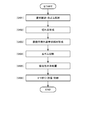
- FIG. 3 is a figure showing the flow of each process of the manufacturing line of the diapar 1 in 1st Embodiment.
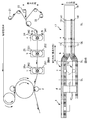
- Drawing 4A is a schematic diagram explaining the flow of the manufacturing method of diaper 1 of a 1st embodiment.
- FIG. 4B is a schematic view illustrating the exterior strip-shaped member 17 in each step in FIG. 4A.
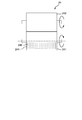
- FIG. 5 is a view on arrow B-B in FIG. 4A.
- FIG. 6 is a figure showing the flow of each process of the manufacturing line of the diapar 1 in 2nd Embodiment.
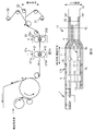
- Drawing 7A is a schematic diagram explaining the flow of the manufacturing method of diaper 1 of a 2nd embodiment.
- FIG. 7B is a schematic view illustrating the exterior strip-shaped member 17 in each step in FIG. 7A.
- FIG. 8 is a view on arrow DD in FIG. 7A.
- Drawing 9A is a schematic diagram explaining the flow of the manufacturing method of diaper 1 of other embodiments.
- FIG. 9B is a schematic cross-sectional view showing the EE cross section of FIG. 9A.
- a method of manufacturing an absorbent article comprising: a plurality of thread rubbers disposed on the skin, wherein the skin-side member is a continuous band-like skin-side member, and the non-skin-side member.
- the non-skin side belt-like member and the non-skin side belt-like member in which the non-skin side belt-like member in the belt-like continuous band-like member is stretched in the transport direction while being transported in the transport direction After the step of disposing the plurality of thread rubbers and the step of disposing a plurality of the thread rubbers between the skin-side band member and the non-skin-side band member, the thread rubber is provided in the longitudinal direction After the steps of forming a plurality of cuts at
- the plurality of cuts be formed to penetrate the skin-side band-shaped member and the non-skin-side band-shaped member.
- air permeability can be improved more by forming the penetrating cut.
- the plurality of cuts be formed along the transport direction.
- the method comprises the step of cutting the thread rubber, and in the step of cutting the thread rubber, the thread rubber is cut using a cutting device provided with a cutting blade, In the step of forming the plurality of cuts, it is desirable to form the cuts using another cutting device provided with another cutting blade.
- the thread rubber is cut to form the low stretch area and the high stretch area, but the step of cutting the thread rubber and the step of forming the cut are different cuts.
- the above-mentioned absorptive article has a belly side exterior member which covers a belly side of a wearer, and a back side exterior member which covers the wearer's back side, After forming the plurality of cuts, the skin-side band member and the non-skin-side band member are cut along the transport direction, and the belly-side exterior band-shaped member in which the belly-side exterior member is continuous in band And a step of forming a back side exterior belt-like member in which the back side exterior member is continuous in a strip shape, and cutting the rubber thread after the step of forming the ventral side exterior belt-like member and the back side exterior belt-like member It is desirable to carry out the following steps.
- the skin side belt-like member and the non-skin side belt-like member are cut to form the belly side exterior belt shape member and the back side exterior belt shape member
- the rubber By cutting the rubber, it is possible to make each of the positions at which the thread rubbers of the ventral-side exterior belt-shaped member and the back-side exterior belt-shaped member cut.
- a method of manufacturing such an absorbent article comprising the step of cutting the thread rubber, comprising: a cutting blade for cutting the thread rubber; and a cutting blade for forming the plurality of cuts, wherein the movable moving member is movable It is desirable to prepare and cut the rubber thread and form the plurality of cuts using the moving member.
- the absorbent article can be manufactured with a more compact manufacturing apparatus by performing the formation of the cuts and the cutting of the thread rubber with the same moving member.
- the above-mentioned absorptive article has a belly side exterior member which covers a belly side of a wearer, and a back side exterior member which covers the wearer's back side,
- the skin side belt-like member and the non-skin side belt-like member are cut along the conveying direction, and the belly-side exterior belt-like member and the back-side armor member are continuously formed in band-like fashion. It is desirable to perform the process of cutting the rubber thread and the process of forming the plurality of cuts after the process of forming the dorsal exterior belt-like member.
- a rotatable rotating body is prepared, and at a certain position in the rotation direction of the rotating body, the plurality of thread rubbers are used as the skin side belt-like member and the non-skin side belt-like member. And between the skin side band member, the non-skin side band member and the rubber thread, to the other position in the rotational direction, and the plurality of cuts are arranged at the other position. It is desirable to form
- a thread rubber is disposed between the skin-side band member and the non-skin-side band member at a certain position on the same rotating body, and a plurality of cuts are formed at other positions.
- the rotating body has a protrusion projecting radially outward, and another protrusion, and at least a portion of the rubber thread includes a protrusion and the other. It is desirable to convey the skin side belt-like member, the non-skin side belt-like member and the rubber thread in the rotation direction in a state of being inserted between the protrusions.
- a rubber thread is inserted between a protrusion and another protrusion that protrudes radially outward of the rotating body.
- the rotating body includes a plurality of protrusions including the certain protrusion and the other protrusion, and the skin side belt-like member and the non-skin side belt-like member Among them, it is preferable that the skin-side belt-like member, the non-skin-side belt-like member and the rubber thread be transported in the rotational direction in a state where the belt-like members located on the rotating body side are in contact with only the plurality of protrusions.
- the rotary member is applied even when the adhesive is applied to the thread rubber by conveying the belt-like member located on the rotary member side in a state in which the belt-like member is in contact with only the projections of the rotary member It is possible to reduce the possibility of adhesion of the adhesive.
- An absorbent article for producing an absorbent article comprising a plurality of thread rubbers disposed on the skin, wherein the skin-side member is a continuous band-like skin-side member, and the non-skin-side member
- the non-skin side belt-like member and the non-skin side belt-like member in which the non-skin side belt-like member in the belt-like continuous band-like member is stretched in the transport direction while being transported in the transport direction After arranging the plurality of thread rubbers between the skin side band-like member and the non-skin side band-like member, a position where the thread rubber is provided in the vertical direction After forming a plurality of cuts and a plurality of cuts forming the plurality of cuts at different positions from It is a manufacturing apparatus of an absorbent article characterized by having a cutting part
- a thread rubber is disposed between the skin-side band member and the non-skin-side band member, and then a cut is formed, and then the skin-side band member and the non-skin side band-shaped member By cutting, it is possible to reduce the displacement due to material transportation, and it is possible to reduce the possibility of the thread rubber being visible from the cut.
- FIG. 1 is a schematic front view of the diaper 1 of the first embodiment.
- FIG. 2A is a plan view of the diaper 1 in the unfolded state.
- FIG. 2B is a central cross-sectional view taken along the line AA in FIG. 2A.
- the diaper 1 is disposed in the crotch region of the wearer by covering the belly side exterior member 11 covering the belly side of the wearer, the back side exterior member 12 covering the wearer's back side, and the crotch of the wearer. It has the absorptive main body 13 to absorb, and the waist opening 1HB and a pair of leg openings 1HL and 1HL are formed.
- the diaper 1 in the unfolded state shown in FIG. 2A is folded in half with the substantially central position CL in the longitudinal direction as the folding position, and the abdominal exterior member 11 and the back at the lateral end 1se which is the end in each lateral direction. It is formed by connecting the side exterior member 12.
- the diaper 1 in the unfolded state has a “longitudinal direction”, a “horizontal direction” intersecting the vertical direction, and a “thickness direction” intersecting the vertical direction and the lateral direction.
- one side is located on the ventral side of the wearer and the other side is located on the dorsal side of the wearer, so one side is called “ventral side” and the other side is called “back side”.
- line CC in FIG. 2A indicates the lateral center.
- the ventral-side exterior member 11 and the back-side exterior member 12 have a substantially rectangular planar shape, and are disposed above and below the absorbent main body 13 in the longitudinal direction, respectively, and the skin-side member 181 located on the wearer's skin side And the non-skin side member 191 located in the non-skin side of a wearer is piled up in the thickness direction.
- the skin side member 181 and the non-skin side member 191 are flexible sheet members each having stretchability, and are formed of, for example, a non-woven fabric or the like.
- the longitudinal length of the non-skin side member 191 is longer than the longitudinal length of the skin side member 181, and in the unfolded diaper 1 the non-skin side member 191 is a longitudinal end which is an end in the longitudinal direction. It is preferable that a turnback portion FL folded back by 1 he is provided. Thus, the strength of the waist opening 1HB can be improved, and the fit when worn can be improved.
- the plurality of rubber threads 14 are fixed to the skin side member 181 and the non-skin side member 191 with an adhesive such as hot melt.
- the plurality of yarn rubbers 14 imparts stretchability to the diaper 1, imparts stretchability to the waist opening 1HB, and fits the diaper 1 around the waist of the wearer.
- disconnected the thread rubber 14 in the part which the belly side exterior member 11 and the back side exterior member 12 and the absorber 131 overlapped in the thickness direction.
- the influence of expansion and contraction due to the rubber thread 14 is reduced, and the contraction of the absorber 131 in the lateral direction can be suppressed, and the possibility of leakage of excrement and the like due to the contraction of the absorber 131 can be reduced.
- disconnected is provided with the high expansion-contraction area
- the diaper 1 is formed with a plurality of cuts 15.
- the slit 15 is formed in a region in which the linear slit along the lateral direction is not overlapped with the absorbent main body 13 and in which the rubber thread 14 is not provided.
- the cut 15 is preferably provided substantially at the center of the interval between the adjacent rubber threads 14.
- the length of the cut 15 is preferably 1 m to 5 mm, which is a length that prevents a finger of a wearer or the like from entering accidentally, and in particular, 2 to 3 mm is more preferable. With such a length, the wearer can visually recognize the presence of the cut 15 at the time of wearing while preventing the finger of the wearer or the like from entering the cut 15, and it is felt that the breathability is good. It can be done.
- the incision 15 penetrates in the thickness direction of the abdominal exterior member 11 and the dorsal exterior member 12, that is, a slit penetrating the skin side member 181 and the non-skin side member 191. It is preferable to Thereby, air permeability can be improved.
- the absorbent main body 13 has a substantially rectangular shape in a plan view, and is disposed at the center in the lateral direction while aligning the longitudinal direction thereof with the longitudinal direction of the diaper 1.
- the shape of the absorptive main body 13 does not need to be a rectangle like FIG. 2A, for example, may be substantially hourglass shape.
- the absorbent main body 13 is an absorbent body 131 which absorbs and holds liquid, a liquid-permeable surface sheet 132 which transmits excrement such as urine while covering the absorbent body 131 from the skin side of the wearer, and an absorbent body A liquid-impervious back sheet 133 such as a film that covers the non-skin side 131 to prevent liquid leakage from the non-skin side, and a plurality of thread rubbers 134 for forming the leg gathers portion LG.
- the absorbent body 131 is a liquid absorbent fiber such as pulp fiber molded into a predetermined shape such as a substantially rectangular parallelepiped, and a high absorbent polymer is mixed therein.
- the absorber 131 may be coated with a tissue paper.
- a solid gather portion or the like that prevents lateral leakage may be provided at each lateral edge of the absorbent main body 13.
- the diaper 1 in the flat state shown in FIG. 2A is folded with the substantially central position CL in the longitudinal direction as a folding line, and the lateral end 1se of the ventral exterior member 11 and the lateral end 1se of the back exterior member 12 are welded and joined (heat By sealing, a pants-type diaper 1 as shown in FIG. 1 is formed.
- the joined lateral end portions 1se, 1se form the lateral end portions 1s of the diaper 1.
- FIG. 3 is a figure showing the flow of each process of the manufacturing line of the diapar 1 in 1st Embodiment.
- the diaper 1 includes a material conveyance / thread rubber placement step (S101), a cut formation step (S102), a ventral side back side exterior strip-shaped member formation step (S103), a thread rubber It manufactures by a cutting process (S104), an absorptive main body arrangement
- FIG. 4A is a schematic diagram explaining the flow of the manufacturing method of diaper 1 of a 1st embodiment.
- FIG. 4B is a schematic view illustrating the exterior strip-shaped member 17 in each step in FIG. 4A.
- the continuous direction of the skin side band member 18 and the non-skin side band member 19 is also referred to as "MD direction”
- the width direction of the skin side band member 18 and the non skin side band member 19 is "CD direction”. It is also called.
- the three directions of the thickness direction of the skin side belt-like member 18 and the non-skin side belt-like member 19, the MD direction which is the continuous direction, and the CD direction which is the width direction are mutually orthogonally related.
- the material of the diaper 1 is conveyed at a predetermined conveyance speed along a predetermined conveyance direction (MD direction) by an appropriate conveyance mechanism, and each material is placed at a predetermined position. Be placed.
- MD direction predetermined conveyance direction
- “Material of the diaper 1” refers to a skin side belt-like member 18 which is a belt-like member formed continuously in a state where a plurality of skin side members 181 are connected in the lateral direction as shown in FIG.
- the non-skin side belt-like member 19 which is a belt-like member which is continuous in the state where two or more non-skin side members 191 were connected in the cross direction is said. As shown in FIG.
- the non-skin side belt-like member 19 is conveyed from the skin side member roll 22, and the plurality of rubber threads 141 are conveyed from the thread rubber roll 23 in a stretched state in the conveying direction. It is disposed at a predetermined position from above in the thickness direction. Then, the skin-side band-shaped member 20 conveyed from the skin-side member roll 21 is disposed from above the thread rubber 141. An adhesive such as a hot melt is applied to each thread rubber 141, and the skin side belt-like member 18, the thread rubber 14, and the non-skin side belt-like member 19 are adhered to each other to form the outer belt-like member 17.
- each rubber thread 14 and the skin-side belt-like member 18 are superimposed on the non-skin-side belt-like member 19 to be transported.
- the method may be such that the non-skin side belt-like member 19 is overlapped.
- the skin side strip-shaped member 18 is conveyed toward the MD direction in a state where the skin side members 181 adjacent to each other in the MD direction are connected at the cutting point SL.
- the cut portion SL is a reference position when the skin side member 181 is separated from the skin side belt-like member 18 in the two-fold, welding, and cutting step (S106) described later, and the end portion 1s of the diaper 1 formed into a pants type (See Figure 1). The same applies to the non-skin side member 19 as well.
- a plurality of cuts 15 are formed in the outer covering strip 17 by using a cut forming device 24 for forming a plurality of cuts in the outer covering strip 17.
- FIG. 5 is a view on arrow B-B in FIG. 4A.
- the cut forming device 24 includes a cutter roll 241 and an anvil roll 242.
- the anvil roll 242 is a drum-shaped rotating body, and conveys the outer strip member 17 in the rotational direction.
- the cutter roll 241 is a rotating body disposed at a position facing the anvil roll 242 and provided below the anvil roll 242.
- the cutter roll 244 is provided with cutter blocks 244 at regular intervals in the circumferential direction. While the anvil roll 242 rotates, the cutter roll 241 rotates in the opposite direction, so that the anvil block and the cutter block 244 periodically face each other.
- the cutter block 244 is provided with a plurality of cutter portions 245 along the transport direction, and can form the cut 15 when the cutter portion 245 and the anvil block face each other and abut on the exterior strip member 17. At this time, the cutter portion 245 preferably penetrates from the non-skin side belt-like member 19 toward the skin side belt-like member 18. By forming the cut 15 which penetrates the exterior belt-like member 17, the diaper 1 with good breathability can be provided.
- the cut 15 is formed at the position a in FIG. 4A.
- the cut 15 is formed at the position a in FIG. 4B.
- the regions provided with the plurality of cuts 15 are formed at regular intervals.
- the cutter portion 245 of the cutter roll 241 is provided at a position not in contact with the rubber thread 141 of the exterior belt-like member 17. If the cutter portion 245 is provided at a position in contact with the rubber thread 141, the rubber thread 14 may be seen from the cut 15 of the diaper 1 after molding, or the tension of the rubber thread 14 may be unreasonably reduced. It is. Moreover, it is preferable to make the cutter part 245 into the shape along the conveyance direction like the thread rubber 141. This is to reduce the possibility that the rubber thread 14 can be seen from the cut 15 even if a shift due to vibration or the like occurs during transportation of the exterior belt-like member 17.
- a dorsal exterior band member 172 is formed.
- the separation device 25 is provided with a cutter roll 251 and an anvil roll 252, and cuts the outer strip member 17 in the same movement as the cut forming device.
- the thread rubber 141 is cut using the thread rubber cutting device 26 for cutting the thread rubber 141 of the outer strip member 17 to form the low stretch area L.
- two thread rubber cutting devices 26 are installed in the CD direction, and a thread rubber cutting device 26 a for cutting the thread rubber 141 of the belly side exterior belt shape member 18 and a thread rubber of the back side exterior belt shape member 18.
- a rubber thread cutting device 26b (not shown) for cutting 141 is provided.
- the thread rubber cutting devices 26a and 26b are respectively provided with a cutting roll 261 and an anvil roll 262, which are rotating bodies disposed at mutually opposing positions, and a predetermined cutter portion (not shown) is provided on the circumferential surface thereof. It is provided.
- the operation of each roll 261, 262 of the thread rubber cutting device 26a, 26b is basically the same as each roll 241, 242 of the cut forming device 24, but the cut roll 261 of the thread rubber cutting device 26a, 26b Only the rubber thread 141 is cut without cutting the side belt-like member 18 and the non-skin side belt-like member 19.
- a low expansion and contraction region L is formed at the position c in FIG. 4B.
- the absorbent main body 13 is disposed on the upper side in the thickness direction of the ventral outer belt-shaped member 171 and the back outer belt-shaped member 172 so that the longitudinal direction is along the CD direction. And joined.
- the absorptive main body 13 itself shall be separately manufactured by an absorptive main body manufacturing line (not shown).
- the diaper 1 is shape
- a folding line CL at a substantially central position in the longitudinal direction of the diaper 1 at a substantially central position in the longitudinal direction of the absorbent main body 13 such that the ventral belt-like member 18 is inside.
- the belly-side exterior band-shaped member 171 and the back exterior-side band-shaped member 172 are superimposed on each other in the thickness direction, and the exterior band-shaped member 17 becomes continuous in the transport direction.
- the ventral-side exterior belt-like member 171 and the back-side exterior belt-like member 172 in the superimposed state are welded in a predetermined region.
- Welding is performed by heat seal welding or ultrasonic welding using a welding apparatus (not shown). After that, using the cutting device (not shown), the ventral side exterior band member 171 and the back side exterior band member 172 are cut together along the CD direction with reference to the cut position SL, whereby the diaper 1 is manufactured. Be done.
- the incision forming step (S102) is performed before the ventral side dorsal side outer belt-like member forming step (S103) and the thread rubber cutting step (S102). Therefore, it is possible to reduce the influence of displacement of material conveyance caused by passing through the ventral side back side outer belt-like member forming step and the thread rubber cutting step, and to further reduce the possibility of the position of the cut 15 being shifted. it can.
- the cut forming device 24 having the cut roll 241 for forming the cut 15 and the thread rubber cutting device 26 having the cut roll 261 for cutting the thread rubber 141 are separately provided.
- the vibration at the time of forming the cut 15 reduces the possibility that the thread rubber 141 can not be cut at the correct position or the thread rubber 141 can not be cut reliably.
- the thread rubber 141 contracts from the cut portion toward the cut position SL in the MD direction (so-called "cutback"), and it is difficult to control its movement properly. If this cut rubber thread 141 is present at the location where the cut 15 is formed, it will be an obstacle to the formation of the cut 15, and the cut 15 can not be formed accurately. Therefore, as in the present embodiment, by performing the thread forming step (S102) and then performing the thread rubber cutting step (S104), the path 15 is formed without being affected by the thread rubber 141 which has been cut. be able to.
- each of the thread rubber 141 is separated into the belly side exterior belt-like member 171 and the back side exterior belt-like member 172.
- the positions at which the rubber thread 141 in the belly-side exterior belt-like member 171 and the back-side exterior belt-like member 172 are cut can be made different. For this reason, the diapar 1 provided with the expansion-contraction power suitable for each of ventral side and a back side can be manufactured.
- FIG. 6 is a figure showing the flow of each process of the manufacturing line of the diapar 1 in 2nd Embodiment.
- the diaper 1 includes material conveyance / thread rubber arrangement (S201), ventral side back side outer strip-like member forming step (S202), cut formation / thread rubber cutting step (S203).
- Drawing 7A is a schematic diagram explaining the flow of the manufacturing method of diaper 1 of a 2nd embodiment.
- FIG. 7B is a schematic view illustrating the exterior strip-shaped member 17 in each step in FIG. 7A.
- the material of the diaper 1 is conveyed along the MD direction by an appropriate conveyance mechanism, and each material is arranged at a predetermined position.
- a plurality of thread rubbers 141 conveyed from the thread rubber roll 23 are arranged in a state of being stretched in the MD direction.
- non-skin side band-like member 19 conveyed from the non-skin side member roll 22 is disposed thereon, and the adhesive applied to the thread rubber 14 causes the skin-side band member 18, the thread rubber 14, and the non-skin The side strip members 19 are adhered to each other to form the outer strip member 17.
- the exterior strip-shaped member 17 is separated at approximately the center in the CD direction using the separation device 25 for cutting the exterior strip-shaped member 17 along the MD direction.
- a side exterior band member 171 and a back side exterior band member 172 are formed.
- the separation device 25 has the same configuration as that of the first embodiment.
- a plurality of cuts 15 are formed in the ventral outer band-shaped member 171 and the back outer band-shaped member 172 using the cut formation / thread rubber cutting device 27. , Cut the rubber thread 141.
- a slit forming / thread rubber cutting device 27 is installed side by side in the CD direction, and a slit forming / cutting section 27a for processing the belly-side exterior strip-shaped member 171 and a slit formation for processing the back exterior strip-shaped member 172 -A rubber thread cutting device 27b is provided.
- FIG. 8 is a view on arrow DD in FIG. 7A.
- the cut formation / thread rubber cutting devices 27a and 27b respectively include cutter rolls 271a and 271b and anvil rolls 272a and 272b.
- the anvil rolls 272a and 272b are rotating bodies having the same configuration as the anvil roll 242 of the incision forming device 24 of the first embodiment, and a plurality of anvil blocks (not shown) are provided on the circumferential surface thereof.
- the cutter rolls 271a and 272b are rotary members disposed at opposing positions of the anvil rolls 272a and 272b, respectively, and include cutter blocks 274a and 274b and cutter blocks 276a and 276b in the circumferential direction.
- the cutter blocks 274a and 274b are respectively provided with a plurality of cutters 275a and 275b along the transport direction, and the cutters 275a and 275b and the anvil block are opposed to each other so as to form the belly side exterior strip 11 and the back exterior strip.
- a cut 15 can be formed.
- the cutter blocks 276a and 276b are provided with a plurality of cutter portions 277a and 277b each having a shape inclined at a predetermined angle with respect to the transport direction, and the cutter portions 277a and 277b face the anvil block so that 171, the thread rubber 141 is cut when coming into contact with the dorsal exterior belt-like member 172.
- the absorbent main body 13 is arranged on the skin side belt-like member 18 side of the ventral outer armor belt shape member 171 and the dorsal outer armor belt shape member 172. It is joined to the surface of skin side beltlike member 18 of belly side exterior beltlike member 171 and back side exterior beltlike member 172 by an agent etc.
- diapar 1 is manufactured by 2 fold * welding * cutting process (S205) similarly to 1st Embodiment.
- the thread 15 is formed, thereby causing the thread rubber 14 to be cut from the thread 15.
- the cut 15 penetrates the skin side belt-like member 18 and the non-skin side belt-like member 19 in order to improve the air permeability, and the shape of the cut 15 is a shape along the transport direction. Is preferred.
- the formation of the cut 15 and the cutting of the thread rubber 141 are performed by the cut forming / thread rubber cutting device 27 which is the same device, the production of the more compact diaper 1 can be performed on the production line. Further, after the exterior belt-like member 17 is separated into the ventral-side exterior belt-like member 171 and the back-side exterior belt-like member 172, formation of the cut 15 and cutting of the rubber thread 141 are performed.
- the cutting pattern can be different on the ventral side and the dorsal side.
- the material conveyance / thread rubber arrangement step (S101) and the cut formation step (S102) in the first embodiment may be performed while being conveyed on one rotating body.
- Drawing 9A is a schematic diagram explaining the flow of the manufacturing method of diaper 1 of other embodiments. As shown in FIG. 9A, the skin side member roll 21, the non-skin side member roll 22, the thread rubber roll 23, the anvil roll 30, the roll 31 which is a drum-shaped rotating body, and the cutter of the cut forming device 24 in the first embodiment.
- the material conveyance / thread rubber arrangement step (S101) and the cut formation step (S102) are performed using the cutter roll 32 having the same configuration as the roll 24.
- the roll 31 is disposed to face the anvil roll 30, and the cut roll 32 is disposed to face the anvil roll 30.
- the non-skin side member 19 conveyed from the non-skin side member roll 22 is placed on the anvil roll 30.
- a plurality of thread rubbers 141 conveyed from the thread rubber roll 23 are stretched in the MD direction at a position advanced by a predetermined distance in the MD direction from the position where the non-skin side band-like member 19 on the anvil roll 30 is placed.
- the non-skin side belt-like member 19 is disposed from above.
- the skin-side strip-like member 18 conveyed from the skin-side member roll 21 is placed from above the thread rubber 141 at a position advanced by a predetermined distance in the MD direction from the position on the anvil roll 30 where the thread rubber 141 is disposed. Be done. Then, while conveying on the anvil roll 30 in the MD direction, pass between the anvil roll 30 and the roll 31 to adhere the skin side belt-like member 18, the rubber thread 141 and the non-skin side belt-like member 19 The member 17 is formed. Thereafter, when the cutter portion (not shown) of the cutter roll 32 and the anvil roll 30 face each other and abut on the exterior belt-like member 17, the cut 15 is formed.
- the distance from the placement of the thread rubber 141 to the formation of the cut 15 can be shortened, and the displacement of the position caused by the transportation of the material can be reduced. Moreover, the production line of the diaper 1 can be made more compact.
- FIG. 9B is a schematic cross-sectional view showing the EE cross section of FIG. 9A. As shown to FIG. 9B, the anvil roll 30 becomes uneven
- the protrusion 301 is formed along the circumferential surface of the anvil roll 30, and the concave portion 302 which is a recessed portion is also formed along the circumferential surface of the anvil roll 30.
- the recess 302 is a groove into which the rubber thread 14 stretched in the MD direction can be inserted along the MD direction, and has a width and a depth such that the rubber thread 141 can enter.
- the thread rubber 141 disposed on the anvil roll 30 is conveyed to a position facing the cut roll 32 with the thread rubber 141 placed in the recess 302.
- the state in which the thread rubber 141 is put in the recess 302 means a state in which at least a part of the thread rubber 141 has entered the recess 302 as shown in FIG. 9B.
- the non-skin side belt-like member 19 located on the anvil roll 30 side also has irregularities formed in the thickness direction, and partially enters the recess 302.
- the rubber thread 141 By conveying the rubber thread 141 in the concave portion 302, it is possible to reduce the possibility of misalignment of the rubber thread 14 disposed in the material conveyance / thread rubber arranging step (S101), and therefore, cut formation.
- the cut 15 In the step (S102), the cut 15 can be formed at a more accurate position. Thereby, the possibility that the cutter portion 321 of the cutter roll 32 abuts on the position where the rubber thread 141 is disposed can be reduced, and the risk that the rubber thread 14 can be seen from the cut 15 can be further reduced.
- the position of the rubber thread 141 can be determined on the anvil roll 30, the rubber thread 141 can be accurately disposed without using an adhesive for fixing the rubber thread 14, and as a result, it is softer.
- the diaper 1 can also be manufactured.
- the non-skin side belt-like member 19 located on the anvil roll 30 side is conveyed in a state of contacting only the protrusion 301, and the cut 15 is formed on the exterior belt-like member 17. That is, it is preferable that the exterior belt-like member 17 not be in contact with the most recessed portion of the recess 302. By doing so, even when the adhesive is applied to the rubber thread 14, the possibility of the adhesive adhering to the anvil roll 30 can be reduced, and maintenance and management such as cleaning of the device becomes easy.
- the cut 15 shall penetrate the exterior member 10, it is not restricted to this.
- the cut 15 may be provided in either the abdominal exterior member 11 or the dorsal exterior member 12, and does not penetrate the exterior member 10, and may be provided in either the skin side member 181 or the non-skin side member 191.
- the cut 15 may be formed.
- Permeable cut 15 is formed in the part where moisture tends to build up to improve air permeability, and cut 15 is made in either skin side member 181 or non-skin side member 191 in the part where moisture buildup is difficult, material strength May be increased.
- the folded portion FL in which the non-skin-side member 191 is folded is formed at the longitudinal end portion 1 he.
- a reinforcing member may be added to the longitudinal end 1he to improve the strength of the waist opening 1HB.
- 3-piece-type disposable diaper 1 was illustrated as an example of an absorbent article, it is not limited to this at all.
- a two-piece disposable diaper or tape having, as a first component, an outer covering sheet having a ventral side, a crotch and a back side as a first part, and an absorbent main body fixed to the skin side of the outer covering sheet It may be used in the manufacture of formula disposable diapers.
- 1 diaper (disposable diaper), 1HB waist opening, 1HL leg opening, 1he longitudinal end, 1se horizontal end, 1s end 10 exterior member, 11 ventral exterior member, 12 back exterior member, 13 Absorbent body, 131 absorber, 132 top sheet, 133 back sheet, 134 thread rubber, 14 thread rubber, 141 thread rubber, 15 cuts, 17 exterior belt-like member, 171 belly-side exterior belt-like member, 172 back side exterior belt-like member, 18 skin side band members, 181 skin side members, 19 Non-skin side band member, 191 Non-skin side member, 21 skin side member roll, 22 non-skin side member roll, 23 yarn rubber roll, 24 break forming devices, 241 cutter roll, 242 anvil roll, 244 cutter block, 245 cutter unit 25 separation device, 251 cutter rolls, 252 anvil rolls, 26a, 26b thread rubber cutting device, 261 cutter rolls, 262 anvil rolls, 27a, 27b Break formation and thread rubber cutting device, 271a, 271b cutter rolls, 272a, 27
Landscapes
- Health & Medical Sciences (AREA)
- Epidemiology (AREA)
- Engineering & Computer Science (AREA)
- Biomedical Technology (AREA)
- Heart & Thoracic Surgery (AREA)
- Vascular Medicine (AREA)
- Life Sciences & Earth Sciences (AREA)
- Animal Behavior & Ethology (AREA)
- General Health & Medical Sciences (AREA)
- Public Health (AREA)
- Veterinary Medicine (AREA)
- Absorbent Articles And Supports Therefor (AREA)
- Orthopedics, Nursing, And Contraception (AREA)
Abstract
Description
縦方向及び前記縦方向と交差する横方向を有し、肌側に位置する肌側部材と、非肌側に位置する非肌側部材と、前記肌側部材と前記非肌側部材との間に配置された複数の糸ゴムと、を備える吸収性物品を製造する吸収性物品の製造方法であって、前記肌側部材が帯状に連続してなる肌側帯状部材、及び前記非肌側部材が帯状に連続してなる非肌側帯状部材が、搬送方向に搬送される間に、前記搬送方向に伸張させた状態の複数の糸ゴムを、前記肌側帯状部材と前記非肌側帯状部材との間に配置する工程と、複数の前記糸ゴムを、前記肌側帯状部材と前記非肌側帯状部材との間に配置する工程の後、前記縦方向において前記糸ゴムが設けられている位置とは異なる位置に、複数の切れ目を形成する工程と、前記複数の切れ目を形成する工程の後、前記肌側帯状部材及び前記非肌側帯状部材を一緒に切断して、前記肌側部材及び前記非肌側部材を形成する工程とを有することを特徴とする吸収性物品の製造方法である。
本発明の他の特徴については、本明細書及び添付図面の記載により明らかにする。
縦方向及び前記縦方向と交差する横方向を有し、肌側に位置する肌側部材と、非肌側に位置する非肌側部材と、前記肌側部材と前記非肌側部材との間に配置された複数の糸ゴムと、を備える吸収性物品を製造する吸収性物品の製造方法であって、前記肌側部材が帯状に連続してなる肌側帯状部材、及び前記非肌側部材が帯状に連続してなる非肌側帯状部材が、搬送方向に搬送される間に、前記搬送方向に伸張させた状態の複数の糸ゴムを、前記肌側帯状部材と前記非肌側帯状部材との間に配置する工程と、複数の前記糸ゴムを、前記肌側帯状部材と前記非肌側帯状部材との間に配置する工程の後、前記縦方向において前記糸ゴムが設けられている位置とは異なる位置に、複数の切れ目を形成する工程と、前記複数の切れ目を形成する工程の後、前記肌側帯状部材及び前記非肌側帯状部材を一緒に切断して、前記肌側部材及び前記非肌側部材を形成する工程とを有することを特徴とする吸収性物品の製造方法である。
<おむつ1の基本的構成>
本実施形態の製造方法によって製造される吸収性物品の一例としてパンツ型の使い捨ておむつ1(以下、「おむつ1」ともいう。)の基本的な構成について説明する。図1は、第1実施形態のおむつ1の概略正面図である。図2Aは、展開状態のおむつ1の平面図である。図2Bは、図2A中のA-A断面図たる中心横断面図ある。
以下、本実施形態に係るおむつ1の製造方法について説明する。
図3は、第1実施形態でおむつ1の製造ラインの各工程のフローを表す図である。図3に示すように、第1実施形態において、おむつ1は、資材搬送・糸ゴム配置工程(S101)、切れ目形成工程(S102)、腹側背側外装帯状部材形成工程(S103)、糸ゴム切断工程(S104)、吸収性本体配置工程(S105)、2つ折り・溶着・切断工程(S106)により製造される。
第2実施形態では、おむつ1の別の製造方法について説明する。
図6は、第2実施形態でおむつ1の製造ラインの各工程のフローを表す図である。図6に示すように、第2実施形態において、おむつ1は、資材搬送・糸ゴム配置(S201)、腹側背側外装帯状部材形成工程(S202)、切れ目形成・糸ゴム切断工程(S203)、吸収性本体配置工程(S204)、2つ折り・溶着・切断工程(S205)により製造される。
以上、本発明の実施形態について説明したが、上記の実施形態は、本発明の理解を容易にするためのものであり、本発明を限定して解釈するためのものではない。また、本発明は、その趣旨を逸脱することなく、変更や改良され得るとともに、本発明にはその等価物が含まれるのはいうまでもない。例えば、以下に示すような変形が可能である。
1HB 胴回り開口部、1HL 脚回り開口部、
1he 縦端部、1se 横端部、1s 端部
10 外装部材、11 腹側外装部材、12 背側外装部材、
13 吸収性本体、
131 吸収体、132 表面シート、133 裏面シート、134 糸ゴム、
14 糸ゴム、141 糸ゴム、
15 切れ目、
17 外装帯状部材、171 腹側外装帯状部材、172 背側外装帯状部材、
18 肌側帯状部材、181 肌側部材、
19 非肌側帯状部材、191 非肌側部材、
21 肌側部材ロール、22 非肌側部材ロール、23 糸ゴムロール、
24 切れ目形成装置、
241 カッターロール、242 アンビルロール、
244 カッターブロック、245 カッター部
25 分離装置、
251 カッターロール、252 アンビルロール、
26a、26b 糸ゴム切断装置、
261 カッターロール、262 アンビルロール、
27a、27b 切れ目形成・糸ゴム切断装置、
271a、271b カッターロール、
272a、272b アンビルロール、
274a、274b カッターブロック、
275a、275b カッター部、
276a、276b カッターブロック、
277a、277b カッター部
30 アンビルロール、301 突部、302 凹部、
31 ロール、32 カッターロール、321 カッター部
CL 折り畳み線、FL 折り返し部、L 低伸縮領域、SL 切断箇所、
Claims (12)
- 縦方向及び前記縦方向と交差する横方向を有し、
肌側に位置する肌側部材と、
非肌側に位置する非肌側部材と、
前記肌側部材と前記非肌側部材との間に配置された複数の糸ゴムと、
を備える吸収性物品を製造する吸収性物品の製造方法であって、
前記肌側部材が帯状に連続してなる肌側帯状部材、及び前記非肌側部材が帯状に連続してなる非肌側帯状部材が、搬送方向に搬送される間に、
前記搬送方向に伸張させた状態の複数の糸ゴムを、前記肌側帯状部材と前記非肌側帯状部材との間に配置する工程と、
複数の前記糸ゴムを、前記肌側帯状部材と前記非肌側帯状部材との間に配置する工程の後、前記縦方向において前記糸ゴムが設けられている位置とは異なる位置に、複数の切れ目を形成する工程と、
前記複数の切れ目を形成する工程の後、前記肌側帯状部材及び前記非肌側帯状部材を一緒に切断して、前記肌側部材及び前記非肌側部材を形成する工程と
を有することを特徴とする吸収性物品の製造方法。 - 請求項1に記載の吸収性物品の製造方法において、
前記複数の切れ目を、前記肌側帯状部材及び前記非肌側帯状部材を貫通して形成することを特徴とする吸収性物品の製造方法。 - 請求項1又は2に記載の吸収性物品の製造方法において、
前記複数の切れ目を、前記搬送方向に沿って形成することを特徴とする吸収性物品の製造方法。 - 請求項1から3のいずれか1項に記載の吸収性物品の製造方法において、
前記糸ゴムを切断する工程を有し、
前記糸ゴムを切断する工程では、ある切断刃を備えたある切断装置を用いて前記糸ゴムを切断し、
前記複数の切れ目を形成する工程では、他の切断刃を備えた他の切断装置を用いて前記切れ目を形成することを特徴とする吸収性物品の製造方法。 - 請求項4に記載の吸収性物品の製造方法において、
前記複数の切れ目を形成する工程の後、前記糸ゴムを切断する工程を行うことを特徴とする吸収性物品の製造方法。 - 請求項4又は5に記載の吸収性物品の製造方法において、
前記吸収性物品は、着用者の腹側を覆う腹側外装部材と、前記着用者の背側を覆う背側外装部材とを有しており、
前記複数の切れ目を形成する工程の後、前記肌側帯状部材及び前記非肌側帯状部材を前記搬送方向に沿って切断して、前記腹側外装部材が帯状に連続してなる腹側外装帯状部材及び背側外装部材が帯状に連続してなる背側外装帯状部材を形成する工程を有し、
前記腹側外装帯状部材及び前記背側外装帯状部材を形成する工程の後、前記糸ゴムを切断する工程を行うことを特徴とする吸収性物品の製造方法。 - 請求項1から3のいずれか1項に記載の吸収性物品の製造方法において、
前記糸ゴムを切断する工程を有し、
前記糸ゴムを切断する切断刃と、前記複数の切れ目を形成する切断刃を備え、移動可能な移動部材を準備し、
前記移動部材を用いて、前記糸ゴムを切断及び前記複数の切れ目の形成を行うことを特徴とする吸収性物品の製造方法。 - 請求項7に記載の吸収性物品の製造方法において、
前記吸収性物品は、着用者の腹側を覆う腹側外装部材と、前記着用者の背側を覆う背側外装部材とを有しており、
前記肌側帯状部材及び前記非肌側帯状部材を前記搬送方向に沿って切断して、前記腹側外装部材が帯状に連続してなる腹側外装帯状部材及び背側外装部材が帯状に連続してなる背側外装帯状部材を形成する工程の後、
前記糸ゴムを切断する工程と前記複数の切れ目を形成する工程を行うことを特徴とする吸収性物品の製造方法。 - 請求項1から5のいずれか1項に記載の吸収性物品の製造方法において、
回転可能な回転体を準備し、
前記回転体の回転方向におけるある位置において、
前記複数の糸ゴムを前記肌側帯状部材と前記非肌側帯状部材の間に配置し、
前記回転体を用いて、前記肌側帯状部材、前記非肌側帯状部材及び前記糸ゴムを前記回転方向における他の位置まで搬送し、
前記他の位置において、前記複数の切れ目を形成することを特徴とする吸収性物品の製造方法。 - 請求項9に記載の吸収性物品の製造方法において、
前記回転体は、径方向外側に突出したある突部と、他の突部を有し、
前記糸ゴムの少なくとも一部を、ある突部と他の突部の間に入れた状態で、前記肌側帯状部材、前記非肌側帯状部材及び前記糸ゴムを前記回転方向に搬送することを特徴とする吸収性物品の製造方法。 - 請求項10に記載の吸収性物品の製造方法において、
前記回転体は、前記ある突部と前記他の突部を含む複数の突部を備えており、
前記肌側帯状部材及び前記非肌側帯状部材のうち前記回転体側に位置する帯状部材が、前記複数の突部にのみ接触した状態で、前記肌側帯状部材、前記非肌側帯状部材及び前記糸ゴムを前記回転方向に搬送することを特徴とする吸収性物品の製造方法。 - 縦方向及び前記縦方向と交差する横方向を有し、
肌側に位置する肌側部材と、
非肌側に位置する非肌側部材と、
前記肌側部材と前記非肌側部材との間に配置された複数の糸ゴムと、
を備える吸収性物品を製造する吸収性物品の製造装置であって、
前記肌側部材が帯状に連続してなる肌側帯状部材、及び前記非肌側部材が帯状に連続してなる非肌側帯状部材が、搬送方向に搬送される間に、
前記搬送方向に伸張させた状態の複数の糸ゴムを、前記肌側帯状部材と前記非肌側帯状部材との間に配置する配置部と、
複数の前記糸ゴムを、前記肌側帯状部材と前記非肌側帯状部材との間に配置した後、前記縦方向において前記糸ゴムが設けられている位置とは異なる位置に、複数の切れ目を形成する切れ目形成部と、
前記複数の切れ目を形成した後、前記肌側帯状部材及び前記非肌側帯状部材を一緒に切断して、前記肌側部材及び前記非肌側部材を形成する切断部と
を有することを特徴とする吸収性物品の製造装置。
Priority Applications (3)
| Application Number | Priority Date | Filing Date | Title |
|---|---|---|---|
| JP2016513937A JP6007442B1 (ja) | 2015-06-30 | 2015-06-30 | 吸収性物品の製造方法、及び製造装置 |
| CN201580081086.8A CN107847359B (zh) | 2015-06-30 | 2015-06-30 | 吸收性物品的制造方法以及制造装置 |
| PCT/JP2015/068882 WO2017002207A1 (ja) | 2015-06-30 | 2015-06-30 | 吸収性物品の製造方法、及び製造装置 |
Applications Claiming Priority (1)
| Application Number | Priority Date | Filing Date | Title |
|---|---|---|---|
| PCT/JP2015/068882 WO2017002207A1 (ja) | 2015-06-30 | 2015-06-30 | 吸収性物品の製造方法、及び製造装置 |
Publications (1)
| Publication Number | Publication Date |
|---|---|
| WO2017002207A1 true WO2017002207A1 (ja) | 2017-01-05 |
Family
ID=57123283
Family Applications (1)
| Application Number | Title | Priority Date | Filing Date |
|---|---|---|---|
| PCT/JP2015/068882 Ceased WO2017002207A1 (ja) | 2015-06-30 | 2015-06-30 | 吸収性物品の製造方法、及び製造装置 |
Country Status (3)
| Country | Link |
|---|---|
| JP (1) | JP6007442B1 (ja) |
| CN (1) | CN107847359B (ja) |
| WO (1) | WO2017002207A1 (ja) |
Cited By (1)
| Publication number | Priority date | Publication date | Assignee | Title |
|---|---|---|---|---|
| WO2020213299A1 (ja) * | 2019-04-15 | 2020-10-22 | 株式会社瑞光 | 着用物品の製造方法、着用物品、および着用物品の製造装置 |
Families Citing this family (1)
| Publication number | Priority date | Publication date | Assignee | Title |
|---|---|---|---|---|
| JP7458714B2 (ja) * | 2019-05-20 | 2024-04-01 | ユニ・チャーム株式会社 | 吸収性物品、及び吸収性物品の製造方法 |
Citations (4)
| Publication number | Priority date | Publication date | Assignee | Title |
|---|---|---|---|---|
| JP2008154998A (ja) * | 2006-11-30 | 2008-07-10 | Daio Paper Corp | 紙おむつ |
| JP2012115358A (ja) * | 2010-11-30 | 2012-06-21 | Oji Nepia Co Ltd | 吸収性物品の製造方法 |
| JP2014221122A (ja) * | 2013-05-13 | 2014-11-27 | 花王株式会社 | パンツ型着用物品およびその製造方法 |
| JP2015107223A (ja) * | 2013-12-04 | 2015-06-11 | 花王株式会社 | パンツ型吸収性物品 |
Family Cites Families (1)
| Publication number | Priority date | Publication date | Assignee | Title |
|---|---|---|---|---|
| JP5291224B1 (ja) * | 2012-04-27 | 2013-09-18 | ユニ・チャーム株式会社 | 使い捨ておむつ及び使い捨ておむつの製造方法 |
-
2015
- 2015-06-30 JP JP2016513937A patent/JP6007442B1/ja active Active
- 2015-06-30 CN CN201580081086.8A patent/CN107847359B/zh active Active
- 2015-06-30 WO PCT/JP2015/068882 patent/WO2017002207A1/ja not_active Ceased
Patent Citations (4)
| Publication number | Priority date | Publication date | Assignee | Title |
|---|---|---|---|---|
| JP2008154998A (ja) * | 2006-11-30 | 2008-07-10 | Daio Paper Corp | 紙おむつ |
| JP2012115358A (ja) * | 2010-11-30 | 2012-06-21 | Oji Nepia Co Ltd | 吸収性物品の製造方法 |
| JP2014221122A (ja) * | 2013-05-13 | 2014-11-27 | 花王株式会社 | パンツ型着用物品およびその製造方法 |
| JP2015107223A (ja) * | 2013-12-04 | 2015-06-11 | 花王株式会社 | パンツ型吸収性物品 |
Cited By (3)
| Publication number | Priority date | Publication date | Assignee | Title |
|---|---|---|---|---|
| WO2020213299A1 (ja) * | 2019-04-15 | 2020-10-22 | 株式会社瑞光 | 着用物品の製造方法、着用物品、および着用物品の製造装置 |
| JPWO2020213299A1 (ja) * | 2019-04-15 | 2020-10-22 | ||
| JP7330265B2 (ja) | 2019-04-15 | 2023-08-21 | 株式会社瑞光 | 着用物品の製造方法、着用物品、および着用物品の製造装置 |
Also Published As
| Publication number | Publication date |
|---|---|
| CN107847359A (zh) | 2018-03-27 |
| CN107847359B (zh) | 2018-12-14 |
| JP6007442B1 (ja) | 2016-10-12 |
| JPWO2017002207A1 (ja) | 2017-06-29 |
Similar Documents
| Publication | Publication Date | Title |
|---|---|---|
| EP3257488B1 (en) | Method and device for manufacturing sheet member for absorptive articles | |
| JP5789730B1 (ja) | 吸収性物品に係るシート状部材の製造方法、及び製造装置 | |
| EP2460499B1 (en) | Web conveying device and web conveying method | |
| EP3363418A1 (en) | Conveying method and conveying device of cut sheet for absorbent article | |
| US10343343B2 (en) | Method for manufacturing absorbent article | |
| US10201459B2 (en) | Method for manufacturing absorbent article | |
| EP2055278A1 (en) | Disposable pants-type wearing article | |
| US20140087933A1 (en) | Method for manufacturing absorbent article | |
| WO2017002207A1 (ja) | 吸収性物品の製造方法、及び製造装置 | |
| US8460264B2 (en) | Wearing article and method for making the same | |
| RU2687618C2 (ru) | Устройство для производства и способ производства одноразового подгузника типа нижнего белья | |
| EP3111901B1 (en) | Method for manufacturing absorbent article | |
| JP6393503B2 (ja) | パンツ型吸収性物品 | |
| WO2017183257A1 (ja) | パンツ型の吸収性物品、及び、パンツ型の吸収性物品の製造方法 | |
| EP3111902B1 (en) | Manufacturing method for absorbent article | |
| JP5879379B2 (ja) | 吸収性物品製造装置 | |
| JP2006181172A (ja) | 吸収性物品及び吸収性物品の製造方法 |
Legal Events
| Date | Code | Title | Description |
|---|---|---|---|
| ENP | Entry into the national phase |
Ref document number: 2016513937 Country of ref document: JP Kind code of ref document: A |
|
| WWE | Wipo information: entry into national phase |
Ref document number: IDP00201601781 Country of ref document: ID |
|
| 121 | Ep: the epo has been informed by wipo that ep was designated in this application |
Ref document number: 15897134 Country of ref document: EP Kind code of ref document: A1 |
|
| NENP | Non-entry into the national phase |
Ref country code: DE |
|
| 122 | Ep: pct application non-entry in european phase |
Ref document number: 15897134 Country of ref document: EP Kind code of ref document: A1 |