WO2016208759A1 - 霧化ユニット - Google Patents
霧化ユニット Download PDFInfo
- Publication number
- WO2016208759A1 WO2016208759A1 PCT/JP2016/068932 JP2016068932W WO2016208759A1 WO 2016208759 A1 WO2016208759 A1 WO 2016208759A1 JP 2016068932 W JP2016068932 W JP 2016068932W WO 2016208759 A1 WO2016208759 A1 WO 2016208759A1
- Authority
- WO
- WIPO (PCT)
- Prior art keywords
- liquid holding
- heating element
- holding member
- wire
- contact
- Prior art date
Links
Images


Classifications
-
- A—HUMAN NECESSITIES
- A61—MEDICAL OR VETERINARY SCIENCE; HYGIENE
- A61M—DEVICES FOR INTRODUCING MEDIA INTO, OR ONTO, THE BODY; DEVICES FOR TRANSDUCING BODY MEDIA OR FOR TAKING MEDIA FROM THE BODY; DEVICES FOR PRODUCING OR ENDING SLEEP OR STUPOR
- A61M11/00—Sprayers or atomisers specially adapted for therapeutic purposes
- A61M11/04—Sprayers or atomisers specially adapted for therapeutic purposes operated by the vapour pressure of the liquid to be sprayed or atomised
- A61M11/041—Sprayers or atomisers specially adapted for therapeutic purposes operated by the vapour pressure of the liquid to be sprayed or atomised using heaters
- A61M11/042—Sprayers or atomisers specially adapted for therapeutic purposes operated by the vapour pressure of the liquid to be sprayed or atomised using heaters electrical
-
- A—HUMAN NECESSITIES
- A24—TOBACCO; CIGARS; CIGARETTES; SIMULATED SMOKING DEVICES; SMOKERS' REQUISITES
- A24F—SMOKERS' REQUISITES; MATCH BOXES; SIMULATED SMOKING DEVICES
- A24F40/00—Electrically operated smoking devices; Component parts thereof; Manufacture thereof; Maintenance or testing thereof; Charging means specially adapted therefor
- A24F40/40—Constructional details, e.g. connection of cartridges and battery parts
- A24F40/46—Shape or structure of electric heating means
-
- A—HUMAN NECESSITIES
- A61—MEDICAL OR VETERINARY SCIENCE; HYGIENE
- A61M—DEVICES FOR INTRODUCING MEDIA INTO, OR ONTO, THE BODY; DEVICES FOR TRANSDUCING BODY MEDIA OR FOR TAKING MEDIA FROM THE BODY; DEVICES FOR PRODUCING OR ENDING SLEEP OR STUPOR
- A61M15/00—Inhalators
- A61M15/06—Inhaling appliances shaped like cigars, cigarettes or pipes
-
- A—HUMAN NECESSITIES
- A24—TOBACCO; CIGARS; CIGARETTES; SIMULATED SMOKING DEVICES; SMOKERS' REQUISITES
- A24F—SMOKERS' REQUISITES; MATCH BOXES; SIMULATED SMOKING DEVICES
- A24F40/00—Electrically operated smoking devices; Component parts thereof; Manufacture thereof; Maintenance or testing thereof; Charging means specially adapted therefor
- A24F40/10—Devices using liquid inhalable precursors
-
- A—HUMAN NECESSITIES
- A61—MEDICAL OR VETERINARY SCIENCE; HYGIENE
- A61M—DEVICES FOR INTRODUCING MEDIA INTO, OR ONTO, THE BODY; DEVICES FOR TRANSDUCING BODY MEDIA OR FOR TAKING MEDIA FROM THE BODY; DEVICES FOR PRODUCING OR ENDING SLEEP OR STUPOR
- A61M2205/00—General characteristics of the apparatus
- A61M2205/82—Internal energy supply devices
- A61M2205/8206—Internal energy supply devices battery-operated
Definitions
- the present invention relates to an atomization unit having a heating element that atomizes an aerosol source without combustion.
- a non-combustion type flavor inhaler for sucking a flavor without burning.
- a non-combustion type flavor inhaler includes an atomization unit that atomizes an aerosol source without combustion.
- the atomization unit includes a reservoir that stores an aerosol source, a liquid holding member that holds the aerosol source supplied from the reservoir, and a heating element (atomization unit) that atomizes the aerosol source held by the liquid holding member.
- the heating element is a coil having a spiral shape and has a shape extending along a predetermined direction.
- the liquid holding member has a shape extending along a predetermined direction, and is disposed so as to be in contact with the outer side surface of the heating element in a direction orthogonal to the predetermined direction (for example, Patent Documents 1 and 2).
- the first feature is an atomization unit, which is formed by a wire having a spiral shape, and includes a coil having a shape extending along a predetermined direction, and a liquid holding member for holding an aerosol source, the coil A first contact that is electrically connected to the first pole of the power source and a second contact that is electrically connected to the second pole side of the power source are provided at an interval on the wire,
- the coil includes a heating part constituted by a wire between the first contact and the second contact arranged closest to each other on the wire, and a wire on one outer side of the heating part on the wire. And a second end portion constituted by a wire outside the heating portion on the wire, and in a direction orthogonal to the predetermined direction. At least a portion of the inner side surface of the liquid holding member is summarized in that which is placed against or in proximity to the heating portion.
- the second feature is summarized in that, in the first feature, the pitches of the wires forming the heating portion, the first end portion, and the second end portion are the same.
- a third feature includes the first conductive member in contact with the coil at the first contact and the second conductive member in contact with the coil at the second contact in the first feature or the second feature.
- the gist is to include a cylindrical member having a cylindrical shape that forms at least a part of the air flow path.
- the cylindrical member includes a first cylindrical member having the first conductive member, and the first conductive member provided at an interval in the predetermined direction.
- the gist is to have a second cylindrical member having a second conductive member.
- a fifth feature is any one of the first feature to the fourth feature, wherein the first conductive member is in contact with the coil at the first contact, and the second conductive member is in contact with the coil at the second contact. And at least one of the first conductive member and the second conductive member is arranged inside or outside the coil.
- a sixth feature is the fifth feature, wherein the first conductive member is disposed between the liquid holding member and the first end portion, and / or the second conductive member is The gist is that the liquid holding member is disposed between the second end portion.
- a seventh feature is any one of the first feature to the sixth feature, wherein the atomizing unit includes a tubular member having a tubular shape forming at least a part of an air flow path, and the tube
- the shaped member has an aerosol inlet through which the aerosol atomized by the heating portion passes through the air flow path, and the heating portion is connected to the aerosol inlet over the entire length of the aerosol inlet in the predetermined direction.
- the gist is that they are arranged adjacent to each other.
- An eighth feature of the seventh feature is that, in the seventh feature, the liquid holding member is disposed adjacent to the aerosol inlet over the entire length of the aerosol inlet in the predetermined direction.
- a ninth feature is any one of the first feature to the eighth feature, wherein the atomization unit includes a reservoir for storing the aerosol source, and the liquid holding member moves the aerosol source by the capillary phenomenon. The gist is to move from the reservoir to the liquid holding member.
- the first end portion and the second end portion are covered with a conductive member having a lower electrical resistivity than the wire.
- the heating portion is not covered with the conductive member.
- the same wire pitch does not mean that the wire pitch is exactly the same, but means that the wire pitch is substantially the same. “Substantially the same” means that the difference in pitch between the wires forming the heating portion, the first portion, and the second portion is not intentionally set. Means allowed.
- the first end portion and the second end portion preferably have a configuration in which the same wire as the wire constituting the heating portion is covered with a conductive member having a lower electrical resistivity than the wire.
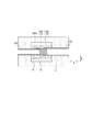
- FIG. 1 is a diagram illustrating a non-burning type flavor inhaler 100 according to an embodiment.
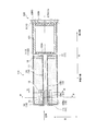
- FIG. 2 is a diagram illustrating an atomization unit 111 according to the embodiment.
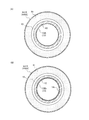
- 3A is a view showing a PP cross section shown in FIG. 2
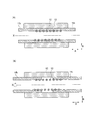
- FIG. 3B is a view showing a QQ cross section shown in FIG. 4 (A) to 4 (D) are views for explaining a method of manufacturing the atomization unit 111 according to the embodiment.
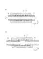
- FIGS. 5A to 5C are views for explaining a method of manufacturing the atomization unit 111 according to the embodiment.
- 6 (A) to 6 (D) are diagrams for explaining a method of manufacturing the atomization unit 111 according to the first modification.
- FIGS. 7A to 7B are diagrams for explaining a method of manufacturing the atomization unit 111 according to the second modification.
- FIGS. 8A to 8B are diagrams for explaining a method of manufacturing the atomization unit 111 according to the third modification.
- FIG. 9 is a diagram illustrating an atomization unit 111 according to the fourth modification.
- FIG. 10 is a diagram illustrating an atomization unit 111 according to the fifth modification.
- FIG. 11 is a diagram illustrating an atomization unit 111 according to the sixth modification.
- FIGS. 12A to 12E are views for explaining a method of manufacturing the atomization unit 111 according to the modification example 7.
- FIGS. 13A to 13D are diagrams for explaining a method of manufacturing the atomization unit 111 according to the modification example 8.
- FIGS. 14A to 14E are views for explaining a method of manufacturing the atomization unit 111 according to the modification example 9.
- FIG. FIG. 15 is a diagram illustrating an atomization unit 111 according to the tenth modification.
- FIG. 16 is a diagram illustrating an atomization unit 111 according to Modification Example 11.
- FIG. 17 is a diagram illustrating an atomization unit 111 according to Modification Example 12.
- 18A and 18B are views for explaining a method for manufacturing the atomization unit 111 according to the modification example 13.
- FIG. FIG. 19 is a diagram illustrating an atomization unit 111 according to Modification Example 14.
- FIG. 20 is a diagram illustrating an atomization unit 111 according to Modification Example 15.
- FIG. 21 is a view showing a liquid amount adjusting member 19 according to Modification Example 15.
- FIGS. 22A and 22B are views for explaining a method for manufacturing the atomization unit 111 according to the sixteenth modification.
- An atomization unit is formed of a wire having a spiral shape, and includes a coil having a shape extending along a predetermined direction, and a liquid holding member that holds an aerosol source.
- a first contact electrically connected to the first pole of the power source and a second contact electrically connected to the second pole side of the power source are provided with an interval, and the coil is
- a heating part constituted by a wire between the first contact and the second contact arranged closest to each other on the wire, and a wire on one outer side of the heating part on the wire.
- the end portions (the first end portion and the second end portion described above) that are likely to be poor in quality are not used as the heating portions, and the portions other than the end portions with the good quality (the heating portions described above). Is used as a heating part, and the uniformity of the amount of generated aerosol can be improved without depending on the manufacturing method of the heating element.
- FIG. 1 is a diagram illustrating a non-burning type flavor inhaler 100 according to an embodiment.
- the non-combustion type flavor inhaler 100 is an instrument for sucking flavor components without combustion, and has a shape extending along a predetermined direction A that is a direction from the non-suction end toward the suction end.
- FIG. 2 is a diagram illustrating an atomization unit 111 according to the embodiment.
- 3A is a diagram showing a PP cross section of the atomization unit 111 shown in FIG. 2
- FIG. 3B is a diagram showing a QQ cross section of the atomization unit 111 shown in FIG. is there.
- the non-burning type flavor inhaler 100 is simply referred to as the flavor inhaler 100.
- the flavor suction device 100 includes a suction device main body 110 and a cartridge 130.
- the suction unit main body 110 constitutes the main body of the flavor suction unit 100 and has a shape to which the cartridge 130 can be connected. Specifically, the suction unit main body 110 has a suction unit housing 110X, and the cartridge 130 is connected to the downstream end of the suction unit housing 110X.
- the aspirator body 110 includes an atomization unit 111 that atomizes an aerosol source without combustion and an electrical unit 112. The atomization unit 111 and the electrical unit 112 are accommodated in the aspirator housing 110X.
- the atomization unit 111 includes an atomization unit housing 111X that constitutes a part of the aspirator housing 110X.
- the atomization unit 111 includes a connection part 111C to the power source included in the electrical unit 112, and an inlet side opening 111O provided on the opposite side of the connection part 111C.
- the connection portion 111C is, for example, a connector connected to a power source.
- the suction opening 111O is an opening that receives the cartridge 130, and is provided on the suction end side. Atomizing unit 111, as shown in FIG.
- the atomizing unit housing 111X has a shape (for example, a cylindrical shape) extending along the predetermined direction A.
- the connection portion 111 ⁇ / b> C described above is omitted, but the connection portion 111 ⁇ / b > C is provided on the non-suction end side (the electrical unit 112 side) of the flange 172.
- the reservoir 11 stores an aerosol source.
- the reservoir 11 has a configuration (size, material, structure, etc.) suitable for storing an aerosol source used in a plurality of puff operations.
- the reservoir 11 may be a porous body made of a material such as a resin web, or may be a cavity for storing an aerosol source.
- the reservoir 11 is preferably capable of storing more aerosol sources per unit volume.
- the reservoir 11 only needs to be disposed at a position where an aerosol source can be supplied to the liquid holding member 12, and at least comes into contact with a part of the liquid holding member 12. In the embodiment, it is preferable that at least a part of the reservoir 11 is disposed outside the covering member 15 in the direction B orthogonal to the predetermined direction A as shown in FIGS. 3 (A) and 3 (B).
- the liquid holding member 12 holds the aerosol source supplied from the reservoir 11.
- the liquid holding member 12 moves and holds a part of the aerosol source that can be stored in the reservoir 11 (for example, an aerosol source used in one puff operation) from the reservoir 11 to a position in contact with or close to the heating element 13. It has a structure (size, material, structure, etc.) suitable for.
- the liquid holding member 12 may be a member that moves the aerosol source from the reservoir 11 to the liquid holding member 12 by capillary action.
- the liquid holding member 12 moves the aerosol source to the liquid holding member 12 by contacting the reservoir 11. When the reservoir 11 is a cavity, the contact between the liquid holding member 12 and the reservoir 11 means that the liquid holding member 12 is exposed to the cavity (reservoir 11).
- the liquid holding member 12 is disposed so as to come into contact with the aerosol source filled in the cavity (reservoir 11).
- the liquid holding member 12 is made of glass fiber or porous ceramic.
- the liquid holding member 12 is a wick composed of glass fiber or porous ceramic.
- the liquid holding member 12 preferably has heat resistance that can withstand the heating of the heating element 13. As shown in FIGS. 3A and 3B, the liquid holding member 12 has a cylindrical shape extending along the predetermined direction A.
- At least a part of the inner side surface of the liquid holding member 12 is in contact with or close to the heating element 13.
- the fact that at least a part of the inner side surface of the liquid holding member 12 is close to the heating element 13 means that the heating element 13 can be atomized by the heating element 13 when the liquid holding member 12 holds the aerosol source. This means that the distance between the heating element 13 and the inner side surface of the liquid holding member 12 is maintained so that the distance between the aerosol source and the aerosol source is maintained.
- the distance between the heating element 13 and the inner side surface of the liquid holding member 12 depends on the aerosol source, the type of the liquid holding member 12, the temperature of the heating element 13, and the like, but may be, for example, 3 mm or less, preferably 1 mm or less. Further, that at least a part of the inner side surface of the liquid holding member 12 is close to the heating element 13 means that the distance between the heating element 13 and the inner side surface of the liquid holding member 12 is such that the aerosol source can be atomized by the heating element 13. This means that something is interposed between the heating element 13 and the aerosol source, so that the heating element 13 prevents the aerosol source from being atomized or atomization of the aerosol source. When in the state, it is not said that at least a part of the inner side surface of the liquid holding member 12 is close to the heating element 13.
- the inner side surface of the liquid holding member 12 is in contact with or close to the heating portion 13A of the heating element 13, as shown in FIG.
- a liquid holding member 12 and the tubular member 14 1 is interposed between the first end portion 13B 1, the inner side surface of the liquid holding member 12 are fever the first end portion 13B of the body 13 1 not in contact with or in proximity with.
- the liquid holding member 12 and the tubular member 14 2 is interposed between the second end portion 13B 2, inner side surfaces of the liquid holding member 12 has a second end portion 13B 2 of the heat generating element 13 There is no contact or proximity.
- the heating element 13 is an example of an atomizing unit that atomizes an aerosol source held by the liquid holding member 12.
- the heating element 13 is a resistance heating element that generates heat by a power output supplied to the heating element 13.
- the heating element 13 is a coil that is formed of a wire having a spiral shape and has a shape extending along the predetermined direction A.
- the inside of the heating element 13 forms at least a part of an air flow path that is a flow path of air sucked from the suction end (the outlet 130O shown in FIG. 1).
- the inside of the heating element 13 is hollow.
- the heating element 13 has a heating portion 13A, a first end portion 13B 1, and a second end portion 13B 2.
- a first contact electrically connected to the first pole of the power source and a second contact electrically connected to the second pole side of the power source are provided on the wire with an interval therebetween.
- the first contact is comprised of a first end portion 13B 1 and the tubular member 14 1.
- the second contact is formed by the second end portion 13B 2 and the cylindrical member 14 2.
- 13 A of heating parts are comprised by the wire between the 1st contact and the 2nd contact arrange
- the first end portion 13B 1 in the embodiment, the downstream side of the wire in the air flow path
- the second end portion 13B 2 in the embodiment, the upstream side of the wire in the air passage
- Heated portion 13A, the pitch of the wire forming the first end portion 13B 1 and the second end portion 13B 2 are the same. It should be noted that “pitch” means the interval between adjacent wires in the predetermined direction A.
- the same wire pitch does not mean that the wire pitch is exactly the same, but means that the wire pitch is substantially the same.
- the heated portion 13A it indicates that the difference in pitch of the wire forming the first end portion 13B 1 and the second end portion 13B 2 has not been intentionally set, manufacturing errors, etc. It means that the difference of the degree caused by is allowed.
- Tubular member 14 has a cylindrical shape and includes a tubular member 14 1 and the cylindrical member 14 2.
- the tubular member 14 1 and the cylindrical member 14 2 has a cylindrical shape that forms at least part of the air passage communicating from the inlet 112A to the outlet 130o (mouthend). That is, the tubular member 14 1 constitutes the first tubular member, the tubular member 14 2, a second tubular member disposed at a tubular member 14 1 and the distance in a predetermined direction A Constitute.
- Each of the tubular member 14 1 and the cylindrical member 14 2 without having an opening on the outer side surface of the tubular member 14 1 and the cylindrical member 14 2, it is preferable to have a fully closed tubular shape.
- the inner diameter of the tubular member 14 1 is the same as the tubular member 14 and second inner diameter.
- the cylindrical member 14 has an aerosol inlet that allows the aerosol atomized by the heating element 13 to pass through the air flow path.
- the tubular member 14 includes a tubular member 14 1 and the cylindrical member 14 2, aerosol inlet is the spacing between the tubular member 14 1 and the cylindrical member 14 2.
- the heating portion 13A described above is disposed so as to be adjacent to the aerosol inlet over the entire length of the aerosol inlet in the predetermined direction A.
- the liquid holding member 12 described above is disposed so as to be adjacent to the aerosol inlet over the entire length of the aerosol inlet in the predetermined direction A.
- the aerosol source held by the liquid holding member 12 can be efficiently used as the heating portion 13A by using a portion having good quality other than the end portion of the wire constituting the heating element 13 (coil). Can be atomized.
- adjacent may be an arrangement relationship in which the heating portion 13A (or the liquid holding member 12) is exposed to the aerosol inlet, and the heating portion 13A (or the liquid holding member 12) and the aerosol inlet are There may be an arrangement relationship in which a gap exists between them, or an arrangement relationship in which a part of the heating portion 13A (or the liquid holding member 12) enters the aerosol inlet.
- the heating portion 13A (or the liquid holding member 12) is adjacent to the aerosol inlet, the arrangement relationship between the heating portion 13A and the inner side surface of the liquid holding member 12 satisfies the above-described contact or proximity relationship. Should be noted.
- Part or all of the cylindrical member 14 is made of a conductive member having a lower electrical resistivity than the wire constituting the heating portion 13 ⁇ / b> A, and the first contact and the second contact are brought into contact with the heating element 13.
- the cylindrical member 14 is made of, for example, aluminum or stainless steel (SUS).
- the tubular member 14 1, the first conductive member in contact with the first end portion 13B 1 at the first contact point constitute the cylindrical member 14 2, and the second end portion 13B 2 in the second contact
- the 2nd conductive member which contacts is comprised. Heated portion 13A described above, is exposed from the tubular member 14 between the tubular member 14 1 and the cylindrical member 14 2.
- the tubular member 14 1 is disposed between the liquid holding member 12 and the first end portion 13B 1 in the orthogonal direction B.
- the cylindrical member 14 2 is disposed between the liquid holding member 12 and the second end portion 13B 2 in the orthogonal direction B.
- the cylindrical member 14 has a barrier member having an outer side surface located between the outer side surface of the heating element 13 and the inner side surface of the liquid holding member 12 in the orthogonal direction B.
- the outer side surface of the cylindrical member 14 is preferably provided at a position facing a part of the inner side surface of the liquid holding member 12. Further, the outer side surface of the cylindrical member 14 is preferably provided at a position facing a part of the inner side surface of the covering member 15. However, the outer side surface of the cylindrical member 14 may be provided at a position not facing the inner side surface of the covering member 15.
- the tubular member 14 preferably has a function of suppressing deformation of the heating element 13 due to stress inward of the liquid holding member 12 covered by the covering member 15.
- the cylindrical member 14 has a strength that can withstand the stress that the covering member 15 presses the outer side surface of the cylindrical member 14 in the orthogonal direction B in the inner direction. Therefore, it is preferable that the cylindrical member 14 is comprised by the electrically-conductive member (for example, stainless steel (SUS)) which has predetermined intensity
- the cylindrical member 14 constituting the air flow path has a predetermined strength, and the outer side surface of the cylindrical member 14 is provided at a position facing a part of the inner side surface of the covering member 15. The deformation of the heating element 13 and the deformation of the air flow path due to the stress of the covering member 15 are suppressed.
- the covering member 15 limits the supply amount of the aerosol source to the liquid holding member 12.
- the covering member 15 has a cylindrical shape extending along a predetermined direction A as shown in FIGS. 3 (A) and 3 (B).
- the covering member 15 is configured by a liquid-impermeable member.
- the covering member 15 may be a liquid-impermeable coating.
- the covering member 15 is preferably constituted by a member having a thermal conductivity lower than that of the aerosol source or the liquid holding member 12. According to such a configuration, the heat of the heating element 13 is not easily transmitted to the aerosol source stored in the reservoir 11.
- the covering member 15 is preferably configured by a member that presses the liquid holding member 12 in the inner direction, for example, a member having elasticity.
- a member constituting the covering member 15 for example, a silicon-based resin or a polyolefin-based resin can be used.
- the covering member 15 is a liquid holding member along a predetermined direction A in a range where the inner side surface of the liquid holding member 12 and the heating element 13 (heating portion 13 ⁇ / b> A) are in contact with or close to each other.
- the outer side surface of the liquid holding member 12 is covered over the entire length of the outer side surface.
- the covering member 15 has a predetermined direction A as an axis within a range in which the inner side surface of the liquid holding member 12 and the heating element 13 (heating portion 13A) are in contact with or close to each other.
- the outer side surface of the liquid holding member 12 is covered over the entire circumference of the outer side surface of the liquid holding member 12 in the circumferential direction.
- the covering member 15 uniformly covers the outer side surface of the liquid holding member 12.
- the covering member 15 may cover the outer side surface of the liquid holding member 12 without having an opening.
- the covering member 15 may have 10 or more openings in which the openings are arranged at equal intervals in the predetermined direction (the extending direction of the liquid holding member 12) and / or the circumferential direction with the predetermined direction as an axis.
- the covering member 15 has a plurality of openings arranged at equal intervals as described above, and the covering area which is the area of the outer side surface of the liquid holding member 12 covered by the covering member 15 is liquid holding. It may be 60% or more of the area of the outer side surface of the member 12.
- the covering member 15 has 10 or more openings arranged at equal intervals as described above, and the covering area is 60% or more of the area of the outer side surface of the liquid holding member 12. Good.
- the range in which the covering member 15 uniformly covers the outer side surface of the liquid holding member 12 may be only the range in which the inner side surface of the liquid holding member 12 and the heating element 13 (heating portion 13A) are in contact with or close to each other. The entire range in which the inner side surface of the member 15 and the outer side surface of the liquid holding member 12 contact each other may be used.
- the covering member 15 holds the liquid even in a range where the inner side surface of the liquid holding member 12 and the heating element 13 (heating portion 13A) are not in contact with or close to each other.
- the outer side surface of the member 12 may be covered.
- covering member 15 has an inner side surface of the covering member 15
- the outer side surface of the liquid holding member 12 may be covered over the entire length of the outer side surface of the liquid holding member 12 along the predetermined direction A.
- the outer side surface of the liquid holding member 12 may be covered over the entire circumference of the outer side surface of the liquid holding member 12 in the circumferential direction about the axis.
- the covering member 15 presses the outer side surface of the liquid holding member 12 in the inner direction in the orthogonal direction B, so that the inner side surface of the liquid holding member 12 is heated by a stress that does not deform the heat generating member 13. 13 is preferably brought into contact with or close to 13.
- the thickness of the liquid holding member 12 covered with the covering member 15 is preferably smaller than the thickness of the liquid holding member 12 not covered with the covering member 15.
- the covering member 15 is liquid even in a range where the inner side surface of the liquid holding member 12 and the heating element 13 (heating portion 13A) are not in contact with or close to each other. and covering the outer side surface of the holding member 12, to the extent that the first end portion 13B 1 is provided, the tubular member 14 1 is provided on the inner side of the covering member 15, the second end portion ranges 13B 2 is provided it is preferable that the cylindrical member 14 2 is provided on the inner side of the covering member 15.
- the cap 16 is a member that closes the supply port for supplying the aerosol source to the reservoir 11.
- the supply port is provided at the end of the reservoir 11 (hereinafter, downstream end) on the downstream side of the air flow path.
- the supply port is provided on the opposite side of the connection portion 111C to the power source (that is, the suction side opening 111O side) with the reservoir 11 as a reference.
- the supply port is opened toward a predetermined direction (in FIG. 2, downstream in the predetermined direction A) in which the aerosol atomized by the heating element 13 is directed toward the suction side opening 111O. It arrange
- the connecting portion 111C, the reservoir 11, the cap 16, and the inlet side opening 111O are arranged on a straight line.
- Cap 16 it is preferably secured to the suction housing 110X and / or the tubular member 14 1. Due to the movement of the cap 16 separating from the reservoir 11 (here, the downstream movement), at least one of the heating element 13 and the power supply member is damaged.
- the power supply member may be a member that electrically connects the heating element 13 and the power source.
- the power supply member is, for example, a tubular member 14, a flange 17, a tubular member 14 or a lead wire (not shown in FIG. 2) that connects the flange 17 and a power source.
- the wiring of the lead wire is not particularly limited.
- the lead wire may be connected to the power source through the atomization unit housing 111X.
- the flange 17 is made of a conductive member, and, for example, the above-described lead wire is connected thereto.
- the flange 17 has a flange 17 1 that leads are connected, extending from the first pole of the power source, and a flange 17 2 leads are connected, extending from the second pole of the power supply.
- the flange 17 1 is fixed to the cylindrical member 14 1
- the flange 17 2 is fixed to the cylindrical member 14 2 .
- Flange 17 1 may be fixed to the cap 16.
- the flange 17 and the lead wire connected to the flange 17 are an example of a power supply member.
- Power supply member includes a first power supply portion including a portion extending toward the connecting portion 111C side from the heating element 13 to the power supply (e.g., a lead wire connected to the flange 17 2 and the flange 17 2), the heating element 13 other side of the connection portion 111C (i.e., mouthend side opening 111O side) from and a second power supply portion including a portion extending toward the (e.g., lead wire connected to the flange 17 1 and the flange 17 1).
- the movement of separating the cap 16 from the reservoir 11 causes, for example, the second power supply portion (for example, the lead wire connected to the flange 17 1 and the flange 17 1 ). Will be damaged.
- breakage means an event in which the function of each member decreases.
- “damage” the deformation of the heating member 13, contact failure between the cylindrical member 14 and the heating element 13, dropping of the flange 17 1, separation of the leads from the flange 17 1, and broken lead wires It should be noted that the concept includes.
- the power supply member is provided on at least a part of the separation direction side of the cap 16 when the separation direction is the direction in which the cap 16 is separated from the reservoir 11.
- the power supply member may be disposed through the inside of the cap 16.
- the power supply member may be fixed to the cap 16.
- the cap 16 since the cap 16 is secured to the tubular member 14 1, with the separation of the cap 16, the deformation of the heating element 13, and contact failure between the cylindrical member 14 and the heating element 13 occurs.
- the flange 17 because it is provided in the downstream end face of the cap 16, with the separation of the cap 16, falling off of the flange 17, separation of the leads from the flange 17, and resulting broken lead wires.
- the flange 17 1 is fixed to the tubular member 14 1 and the cap 16, with the separation of the cap 16, the deformation of the heating member 13, the tubular member 14 and the contact between the heating element 13 such as bad Occurs.
- the heating element 13 is more easily damaged than the power supply member such as the cylindrical member 14, the flange 17, and the lead wire.
- the lead wire is more easily damaged than the cylindrical member 14 and the flange 17.
- the aerosol source is a liquid such as glycerin or propylene glycol.
- the aerosol source is held by a porous body made of a material such as a resin web.
- the porous body may be made of a non-tobacco material or may be made of a tobacco material.
- the aerosol source may contain a flavor component (such as a nicotine component). Alternatively, the aerosol source may not include a flavor component.
- the electrical unit 112 has an electrical unit housing 112X that constitutes a part of the aspirator housing 110X.
- the electrical unit 112 has an inlet 112A.
- the air flowing in from the inlet 112A is guided to the atomization unit 111 (heating element 13) as shown in FIG.
- the electrical unit 112 has a power source for driving the flavor inhaler 100 and a control circuit for controlling the flavor inhaler 100.
- the power supply and control circuit are accommodated in the electrical unit housing 112X.
- the electrical unit housing 112X has a cylindrical shape (for example, a cylindrical shape) extending along the predetermined direction A.
- the power source is, for example, a lithium ion battery.
- the control circuit is constituted by, for example, a CPU and a memory.
- the cartridge 130 is configured to be connectable to the aspirator body 110 constituting the flavor inhaler 100.
- the cartridge 130 is provided downstream of the atomization unit 111 on the air flow path communicating from the inlet 112A to the outlet 130O (suction end).
- the cartridge 130 does not necessarily have to be physically provided on the suction end side of the atomization unit 111 in terms of physical space, and is atomized on the air flow path that guides the aerosol generated from the atomization unit 111 to the suction end side. What is necessary is just to be provided downstream from the unit 111.
- the cartridge 130 includes a cartridge housing 131, a flavor source 132, a mesh 133A, and a filter 133B.
- the cartridge housing 131 has a cylindrical shape (for example, a cylindrical shape) extending along the predetermined direction A.
- the cartridge housing 131 accommodates the flavor source 132.
- the cartridge housing 131 is configured to be inserted along the predetermined direction A into the aspirator housing 110X.
- the flavor source 132 is provided downstream of the atomization unit 111 on the air flow path.
- the flavor source 132 imparts a flavor component to the aerosol generated from the aerosol source. In other words, the flavor imparted to the aerosol by the flavor source 132 is carried to the mouth end.
- the flavor source 132 is constituted by a raw material piece that imparts a flavor component to the aerosol generated from the atomization unit 111.
- the size of the raw material piece is preferably 0.2 mm or more and 1.2 mm or less. Furthermore, the size of the raw material pieces is preferably 0.2 mm or more and 0.7 mm or less. Since the specific surface area increases as the size of the raw material piece constituting the flavor source 132 is smaller, the flavor component is easily released from the raw material piece constituting the flavor source 132. Therefore, the amount of the raw material pieces can be suppressed when applying the desired amount of flavor component to the aerosol.
- molded the cut tobacco and the tobacco raw material in the granule can be used as a raw material piece which comprises the flavor source 132.
- the flavor source 132 may be a molded body obtained by molding a tobacco material into a sheet shape.
- the raw material piece which comprises the flavor source 132 may be comprised by plants (for example, mint, an herb, etc.) other than tobacco.
- the flavor source 132 may be provided with a fragrance such as menthol.
- the raw material piece constituting the flavor source 132 is obtained, for example, by sieving in accordance with JIS Z 8815 using a stainless steel sieve in accordance with JIS Z 8801.
- a stainless steel sieve having an opening of 0.71 mm the raw material pieces are screened for 20 minutes by a dry and mechanical shaking method, and then passed through a stainless steel sieve having an opening of 0.71 mm. Get raw material pieces.
- a stainless steel sieve having an opening of 0.212 mm the raw material pieces are sieved for 20 minutes by a dry and mechanical shaking method, and then passed through a stainless steel sieve having an opening of 0.212 mm. Remove raw material pieces.
- the flavor source 132 is a tobacco source having an alkaline pH.
- the pH of the tobacco source is preferably greater than 7, more preferably 8 or more.
- the flavor component generated from the tobacco source can be efficiently taken out by the aerosol.
- the pH of the tobacco source is preferably 14 or less, and more preferably 10 or less. Thereby, damage (corrosion etc.) to the flavor suction device 100 (for example, the cartridge 130 or the suction device main body 110) can be suppressed.
- flavor component generated from the flavor source 132 is conveyed by aerosol, and it is not necessary to heat the flavor source 132 itself.
- the mesh 133A is provided so as to close the opening of the cartridge housing 131 upstream of the flavor source 132, and the filter 133B is provided so as to close the opening of the cartridge housing 131 downstream of the flavor source 132.
- the mesh 133A has such a roughness that the raw material pieces constituting the flavor source 132 do not pass therethrough.
- the roughness of the mesh 133A has, for example, a mesh opening of 0.077 mm or more and 0.198 mm or less.
- the filter 133B is made of a material having air permeability.
- the filter 133B is preferably an acetate filter, for example.
- the filter 133B has such a roughness that the raw material pieces constituting the flavor source 132 do not pass through.
- the flavor suction device 100 detects the suction operation of the user, the flavor suction device 100 starts supplying power output to the heating element 13. As the supply of power output to the heating element 13 starts, atomization of the aerosol source held by the liquid holding member 12 starts. On the other hand, the flavor inhaler 100 stops supplying the power output to the heating element 13 when the user's suction operation is not detected. As the supply of power output to the heating element 13 is stopped, atomization of the aerosol source held by the liquid holding member 12 is stopped.
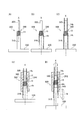
- FIG.4 and FIG.5 is a figure for demonstrating the manufacturing method of the atomization unit 111 which concerns on embodiment.
- the heating element 13 is disposed along a spiral groove or protrusion formed on the side surface of the base member 300 having the axis X extending along the predetermined direction A (step A).
- the base member 300 is a jig including a portion having a cylindrical shape.
- step E by sliding along the tubular member 14 2 the flange 17 2 is fixed in a predetermined direction A, a cylindrical member 14 2 on the outer side surface of the heating element 13 with placing, by sliding along the tubular member 14 1 in a predetermined direction a, to arrange the tubular member 14 1 to the outer side surface of the heating element 13 (step E).
- step E in order to expose the heating portion 13A of the heating element 13, placing the tubular member 14 1 and the cylindrical member 14 2 to each other in a spaced apart state.
- FIG. 4 (C) the by sliding along the housing cap body 111X 1 constituting a part of the atomization unit housing 111X in a predetermined direction A, the flange 17 2 housing cap body 111X 1 Contact with. Subsequently, by sliding the liquid holding member 12 along the predetermined direction A, the liquid holding member 12 is arranged so as to be in contact with or close to at least a part of the heating element 13 (heating portion 13A) (step C). Housing cap body 111X 1 is fixed to the cylindrical member 14 2 and the flange 17 2.
- positioning the liquid holding member 12 so that it may contact or adjoin to the heating part 13A of the heat generating body 13 is liquid to the heating part 13A of the heat generating body 13 by arrangement
- the liquid holding member 12 may be arranged so that the holding member 12 is in contact with or close to the holding member 12.
- the step of arranging the liquid holding member 12 may be a step of arranging the liquid holding member 12 while the liquid holding member 12 presses the outer side surface of the heating portion 13A.
- the step of arranging the liquid holding member 12 may be a step of arranging the liquid holding member 12 so as to contact the entire circumference of the outer side surface of the heating portion 13A.
- positioning the liquid holding member 12 is a process of arrange
- the covering member 15 is arranged on the outer side surface of the liquid holding member 12 by sliding the covering member 15 along the predetermined direction A. Due to the arrangement of the covering member 15, the heated portion 13 ⁇ / b> A of the heating element 13 is in good contact with or close to the liquid holding member 12.
- the reservoir 11 is disposed in a space formed by the housing cap body 111X 1 , the housing cylinder body 111X 2, and the cylindrical member 14. A part of the reservoir 11 is preferably disposed also outside the covering member 15. Placement of the reservoir 11 may be performed before fixing the housing cylinder 111X 2 in the housing cap body 111X 1.
- the fixing process of the heating element 13 and the cylindrical member 14 may be performed after the process shown in FIG. 4B and before the process shown in FIG.
- the fixing process of the heating element 13 and the cylindrical member 14 is preferably performed before the process shown in FIG. 5A, and more preferably performed before the process shown in FIG. Accordingly, it is possible to fix the heating element 13 and the cylindrical member 14 in a state where there are no extra members on the outer side surface of the cylindrical member 14, and it is easy to fix the heating element 13 and the cylindrical member 14.
- Cap 16 is secured to the housing cylinder 111X 2. Note that the upstream end of the reservoir 11, it should be noted that is closed by a housing cap member 111X 1. Then, placing the flange 17 1 on the downstream end face of the cap 16. The flange 17 1 is fixed to the cylindrical member 14 1 .
- the base member 300 (jig) is rotated about the axis X as a rotation axis to separate all of the heating elements 13 from the grooves or protrusions of the base member 300 (step B). ).
- a space used as an air flow path is formed inside the heating element 13 by the process shown in FIG.
- FIG. 5C and the process shown in FIG. a step of forming a inlet aerosol passing the atomized aerosol to the inside of the heating element 13 (distance between the tubular member 14 1 and the cylindrical member 14 2) by.
- the aerosol inlet is in communication with the inside of the heating element 13 only after the heating element 13 is separated from the base member 300. Therefore, the process shown in FIG. 5C is a process for forming the aerosol inlet. It should be noted that there are.
- the step shown in FIG. 5C is a step of forming at least a part of the air flow path inside the heating element 13 by the separation of the heating element 13. Specifically, in the step shown in FIG. 5C, all of the heating element 13 is separated from the base member 300 (jig), and at least one of the air flow paths is formed inside the heating element 13 by the separation of the heating element 13. It is the process of forming a part. In such a case, it is preferable that a step (step G) of arranging a flow path forming member that forms at least a part of the air flow path is performed before the step shown in FIG.
- the flow path forming member may be considered as, for example, the cylindrical member 14 described above. Therefore, the step of arranging the flow path forming member may be considered as the step shown in FIG.
- the depth of the groove of the base member 300 or the height of the protrusion of the base member 300 is the diameter of the wire forming the heating element 13 from the viewpoint of electrical connection between the tubular member 14 and the heating element 13. It is preferable that it is less than or equal to. On the other hand, the depth of the groove of the base member 300 or the height of the protrusion of the base member 300 is at least half of the diameter of the wire forming the heating element 13 from the viewpoint of holding the heating element 13 by the base member 300. Is preferred.
- the covering member 15 is composed of a liquid-impermeable member. This suppresses excessive supply of the aerosol source.
- the covering member 15 is preferably constituted by a member having a thermal conductivity lower than that of the aerosol source or the liquid holding member 12. According to such a structure, the heat loss in heating atomization is suppressed.
- the covering member 15 is preferably constituted by a member that presses the liquid holding member 12 in the inner direction. According to such a configuration, the liquid holding member 12 can be brought into good contact with or close to the heating element 13.
- the covering member 15 has the entire length of the outer side surface of the liquid holding member 12 along the predetermined direction A in a range where the inner side surface of the liquid holding member 12 and the heating element 13 (heating portion 13A) are in contact with or close to each other. It is preferable to cover the outer side surface of the liquid holding member 12. According to such a configuration, the above-described excessive supply can be further suppressed.
- the covering member 15 is formed on the outer side of the liquid holding member 12 in the circumferential direction with the predetermined direction A as an axis in a range in which the inner side surface of the liquid holding member 12 and the heating element 13 (heating portion 13A) are in contact with or close to each other. It is preferable to cover the outer side surface of the liquid holding member 12 over the entire circumference of the side surface. According to such a configuration, the above-described excessive supply can be further suppressed.
- the covering member 15 uniformly covers the outer side surface of the liquid holding member 12.
- an aerosol source can be uniformly supplied with respect to the heat generating body 13 (heating part 13A), and the atomization efficiency can be improved.
- the covering member 15 may cover the outer side surface of the liquid holding member 12 without having an opening. Thereby, the excessive supply mentioned above can be suppressed more effectively.
- the covering member 15 may have 10 or more openings arranged at equal intervals. By adjusting the number and size of 10 or more openings arranged at equal intervals, not only the above-mentioned excessive supply is suppressed, but also the supply amount of the aerosol source is adjusted to an arbitrary amount, and the aerosol source is made uniform.
- the covering member 15 has a plurality of openings arranged at equal intervals, and the covering area which is the area of the outer side surface of the liquid holding member 12 covered by the covering member 15 is the outside of the liquid holding member 12. It may be 60% or more of the area of the side surface. With such a configuration, the supply amount of the aerosol source can be more effectively suppressed.
- the thickness of the liquid holding member 12 that is covered with the covering member 15 is smaller than the thickness of the liquid holding member 12 that is not covered with the covering member 15, in other words, by the covering member 15.
- a configuration in which the liquid holding member 12 is compressed is preferable. According to such a configuration, a situation in which an excessive amount of aerosol source is held by the liquid holding member 12 due to the compression of the liquid holding member 12 is suppressed.
- the reservoir 11 is disposed outside the covering member 15 in the orthogonal direction B.
- the space outside the covering member 15 is allocated to the reservoir 11 to increase the capacity of the reservoir 11 (that is, the amount of the aerosol source that can be stored by the reservoir 11). The excessive supply mentioned above can be suppressed.
- the cylindrical member 14 constitutes a barrier member having an outer side surface located between the outer side surface of the heating element 13 and the inner side surface of the covering member 15 in the orthogonal direction B.
- the outer side surface of the cylindrical member 14 is preferably provided at a position facing a part of the inner side surface of the liquid holding member 12. Further, the outer side surface of the cylindrical member 14 is preferably provided at a position facing a part of the inner side surface of the covering member 15. According to such a configuration, deformation of the heating element 13 due to stress inward of the liquid holding member 12 covered by the covering member 15 is suppressed.
- the cylindrical member 14 constitutes an air flow path and has a predetermined strength (for example, a strength that can withstand the stress that the covering member 15 presses the outer side surface of the cylindrical member 14 in the orthogonal direction B in the inner direction).
- a predetermined strength for example, a strength that can withstand the stress that the covering member 15 presses the outer side surface of the cylindrical member 14 in the orthogonal direction B in the inner direction.
- the cylindrical member 14 functions as a barrier member in that the deformation of the heating element 13 and the deformation of the air channel due to the stress of the covering member 15 are suppressed.
- the cylindrical member 14 that forms at least a part of the air flow path is formed of a conductive member, and the cylindrical member 14 1 that contacts the first end portion 13B 1 at the first contact point, having 2 contacts and the tubular member 14 2 in contact with the second end portion 13B 2. Therefore, it is possible to reduce the number of parts necessary for forming the air flow path and forming the electrical contact.
- a cap 16 for closing a supply port for supplying an aerosol source to the reservoir 11 is provided. Due to the movement of the cap 16 separating from the reservoir 11 (here, the downstream movement), at least one of the heating element 13 and the power supply member is damaged. Therefore, utilization of the flavor inhaler 100 accompanied by reinjection of the aerosol source to the reservoir 11 can be effectively suppressed. In addition, since the cap 16 closes the supply port provided on the opposite side of the connection portion 111C to the power supply with reference to the reservoir, the use of the flavor inhaler 100 accompanied by the reinjection of the aerosol source described above is effectively suppressed. .
- the power supply member includes a first power supply portion including a portion extending toward the connecting portion 111C side from the heating element 13 to the power supply (e.g., a lead wire connected to the flange 17 2 and the flange 17 2) , the other side of the connection portion 111C from the heat generating element 13 (i.e., mouthend side opening 111O side) second power supply portion including a portion extending toward the (e.g., lead wire connected to the flange 17 1 and the flange 17 1) including. Therefore, it is easy to employ a configuration in which the second power supply portion is damaged by the movement of the cap 16 from the reservoir 11 (here, the downstream movement).
- the coil constituting the heating element 13 includes a heating part 13A constituted by a wire between the first contact and the second contact arranged closest to each other on the wire, and a heating part 13A on the wire.
- a heating part 13A on the wire by one of the outer wires comprises a first end portion 13B 1 constituted and a second end portion 13B 2 constituted by the other of the outer wire in the heated portion 13A on the wire.
- At least a part of the inner side surface of the liquid holding member 12 is in contact with or close to the heating portion 13A.
- a high end potential poor quality in the embodiment, the first end portion 13B 1 and the second end portion 13B 2
- an end of the wire forming the heating member 13 coil
- a portion having a good quality other than the portion in the embodiment, the heated portion 13A
- the uniformity of the amount of generated aerosol can be improved without depending on the manufacturing method of the heating element 13.
- the liquid holding member 12 can be easily disposed over the entire central portion used as the heating member 13A, and atomization with less energy loss is performed.
- the unit 111 is easy to configure.
- the tubular member 14 is constituted by a conductive member, and the tubular member 14 1 in contact with the first end portion 13B 1 at the first contact point, and the second end portion 13B 2 in the second contact and a cylindrical member 14 2 in contact.
- the tubular member 14 1 and the cylindrical member 14 2 (in the embodiment, the outer side surface) side of the heating element 13 is disposed.
- the side surface of the heating element 13 means the outer peripheral surface and inner peripheral surface of the coil when the coil constituting the heating element 13 is considered to be a cylindrical member. Therefore, the side surface of the heating element 13 is actually constituted by the side surface of the wire forming the coil.
- the cylindrical member 14 is a member having a surface, electrical connection between the surfaces is possible, stable electrical connection can be performed, and the heating element 13 is firmly fixed to the cylindrical member 14. can do. Moreover, it becomes easy to perform fixing such as welding.
- tubular member 14 1 in the orthogonal direction B and the liquid holding member 12 is disposed between the first end portion 13B 1
- tubular member 14 2 is provided with a liquid retaining member 12 in the orthogonal direction B No. It is disposed between the second end portions 13B 2. Accordingly, since the heating element 13 is supported by the tubular member 14 1 and the cylindrical member 14 2, inner heating element 13 is also a hollow, deformation of the heating element 13 is suppressed.
- the manufacturing method of the atomization unit 111 is such that the heating element 13 extends along a spiral groove or protrusion formed on the side surface of the base member 300 (jig) having the axis X extending along the predetermined direction A. And the base member 300 is rotated about the axis X as a rotation axis, so that all of the heating elements 13 are separated from the grooves or protrusions of the base member 300. That is, since the heating element 13 is supported by the base member 300 in the manufacturing process of the atomization unit 111, the deformation of the heating element 13 in the manufacturing process of the atomization unit 111 can be suppressed, and the high-quality heating element 13. Can be produced.
- the base member 300 (jig) is rotated about the axis X as a rotation axis, and the entire heating element 13 is moved to the base member. Separated from 300 grooves or protrusions. Suppressing deformation of the heating element 13 in the step of arranging the liquid holding member 12 so as to be in contact with or close to the heating portion 13A of the heating element 13 (particularly, the step of bringing the heating portion 13A into contact with or close to the liquid holding member 12).
- the atomization unit 111 having the high-quality heating element 13 can be manufactured.
- the base member 300 (jig) is rotated about the axis X as a rotation axis, and before the entire heating element 13 is separated from the grooves or protrusions of the base member 300, the outer side surface of the heating element 13 in the orthogonal direction.
- the cylindrical member 14 is disposed on the surface.
- the heating element 13 is always supported by the base member 300 or the cylindrical member 14 in the manufacturing process of the atomization unit 111. Therefore, the deformation of the heating element 13 in the manufacturing process of the atomizing unit 111 can always be suppressed, and the atomizing unit 111 having the high-quality heating element 13 can be manufactured.
- the step of arranging the liquid holding member 12 may be a step of arranging the liquid holding member 12 while the liquid holding member 12 presses the outer side surface of the heating portion 13A.
- the step of arranging the liquid holding member 12 may be a step of arranging the liquid holding member 12 so as to contact the entire circumference of the outer side surface of the heating portion 13A. In these cases, since the liquid holding member 12 is arranged before the heating element 13 is separated from the base member 300, the deformation of the heating element 13 can be suppressed in the step of arranging the liquid holding member 12, and high quality can be achieved.
- An atomization unit 111 having a heating element 13 can be manufactured.
- At least a part of the air flow path may be formed inside the heat generating body 13 by separating the heat generating body 13. Thereby, before the heating element 13 is separated from the base member 300, the entry of foreign matter into the air flow path is suppressed.
- the base member 300 (jig) is rotated about the axis X as a rotation axis. Therefore, all of the heating element 13 is separated from the groove or protrusion of the base member 300. Therefore, the deformation of the heating element 13 accompanying the rotation of the base member 300 can be suppressed, and the atomization unit 111 having the high-quality heating element 13 can be manufactured.
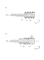
- FIG. 6 is a diagram for explaining a modified example of the process shown in FIG.
- the step of rotating the base member 300 (jig) about the axis X as a rotation axis to separate all the heating elements 13 from the grooves or protrusions of the base member 300 is performed in the middle of the step shown in FIG. Therefore, it should be noted that the first modification is different from the embodiment.
- a sliding member 400 having a cylindrical shape is slid along a predetermined direction A, whereby the sliding member is placed on the outer side surfaces of the heating element 13 and the cylindrical member 14. 400 is arranged. That is, the slide member 400 is slid along the outer side surfaces of the heating element 13 and the cylindrical member 14 in the orthogonal direction B (step C1).
- the base member 300 (jig) is rotated about the axis X as a rotation axis, and all of the heating elements 13 are separated from the grooves or protrusions of the base member 300 (step B).
- the cylindrical member 14 is fixed to the atomizing unit housing 111X (housing cap body 111X 1 ) via the flange 17 or the like.
- the liquid holding member 12 is slid along the outer side surface of the sliding member 400 in the orthogonal direction B (step C2).
- the heating element 13 is covered with the slide member 400, even if the liquid holding member 12 is arranged in a state where all of the heating element 13 is separated from the base member 300 (jig), the liquid holding is performed. Deformation of the heating element 13 due to the arrangement of the member 12 is suppressed.
- the sliding member 400 is removed by sliding the sliding member 400 along a predetermined direction A. That is, the slide member 400 is removed by sliding from between the liquid holding member 12 and the heating element 13 (step C3). Accordingly, it should be noted that the liquid holding member 12 is disposed so as to be in contact with or close to the heating portion 13 ⁇ / b> A of the heating element 13.
- the sliding member 400 is configured by a member that is easier to slide along the predetermined direction A than the liquid holding member 12.
- the frictional force (dynamic frictional force and / or static frictional force) acting between the inner side surface of the sliding member 400 and the outer side surface of the cylindrical member 14 is the inner side surface of the liquid holding member 12 and the outer side surface of the cylindrical member 14.
- the sliding member 400 is configured to be smaller than the frictional force. With this configuration, it is easier to use the sliding member 400 by sliding the liquid holding member 12 than to arrange the liquid holding member 12 alone.
- the rigidity of the sliding member 400 is preferably higher than the rigidity of the liquid holding member 12.
- the liquid holding member 12 is easy to arrange
- the liquid holding member 12 is slid along the outer side surface of the sliding member 400. It is not limited to. Specifically, after the slide member 400 is inserted inside the liquid holding member 12, the slide member 400 is slid along the outer side surface of the tubular member 14 with the slide member 400 inserted inside the liquid holding member 12. The working member 400 may be slid.
- the slide member 400 is removed by sliding after the heating element 13 is separated from the groove or protrusion of the base member 300, but the first modification is not limited to this. Specifically, the step of removing the slide member 400 by sliding may be performed before the step of separating the heating element 13 from the groove or protrusion of the base member 300.
- the depth of the groove of the base member 300 or the height of the protrusion of the base member 300 is equal to or less than the diameter of the wire forming the heating element 13 and is equal to or more than half the diameter of the wire, as in the embodiment. It is preferable that
- the step of separating the heating element 13 from the groove or protrusion of the base member 300 is performed after the cylindrical member 14 is fixed to the atomizing unit housing 111X and / or the heating element 13 is cylinder-like, as in the embodiment. It is preferable to carry out after fixing to the member 14.
- the heating element 13 is separated from the groove or the protrusion of the base member 300 before the liquid holding member 12 is arranged so as to be in contact with or close to the heating portion 13A of the heating element 13.
- the base member 300 can be separated as soon as possible before the assembly of the members such as the liquid holding member 12, and the base member 300 can be diverted to the next semi-finished product manufacturing in a short time. Productivity can be improved.
- the slide member 400 by using the slide member 400, the step of arranging the liquid holding member 12 so as to be in contact with or close to the heating portion 13A of the heating element 13 (for example, sliding the liquid holding member 12) In the step), the deformation of the heating element 13 can be suppressed, and the atomization unit 111 having the high-quality heating element 13 can be manufactured. Further, the liquid holding member 12 can be easily disposed on the outer side surfaces of the heating element 13 and the cylindrical member 14.
- the base member 300 is a jig having a cylindrical shape.
- the base member 300 is illustrated for the tubular member 14 (the tubular member 14 1 and the cylindrical member 14 2) in a case.
- FIG. 7 is a diagram for explaining a method for manufacturing the atomization unit 111 according to the second modification. In FIG. 7, it should be noted that the atomization unit housing 111X, the cap 16, the flange 17, and the like are omitted.
- the heating element 13 extends along a spiral groove or protrusion formed on the inner side surface of the cylindrical member 14 having the axis X extending along the predetermined direction A. And the cylindrical member 14 and the heating element 13 are electrically connected (step A and step D). Here, the cylindrical member 14 is disposed outside the heating element 13.
- the tubular member 14 1 and the cylindrical member 14 2 is continuous in a predetermined direction A.
- the step A is a step of placing the heating element 13 straddling both the tubular member 14 1 and the cylindrical member 14 2.
- liquid holding member 12 is to be noted that they are disposed on the outer side surface of the tubular member 14 in the orthogonal direction B (the tubular member 14 1 and the cylindrical member 14 2).
- step B the axis X in the tubular member 14 1 and the cylindrical member 14 2 of the rotated at least one as a rotation axis, to separate the heating element 13 from the groove or the protrusion. That is, step B, while maintaining the state in which the heating element 13 is arranged straddling both the tubular member 14 1 and the cylindrical member 14 2, the tubular member 14 1 and the cylindrical member 14 2 to each other This is a step of separating.
- the heated portion 13A of the heating element 13 is exposed to the liquid retaining member 12. Further, the liquid holding member 12 is arranged so as to be in contact with or close to the heating portion 13A of the heating element 13 (step C or step C4). Since the gap between the tubular member 14 1 and the cylindrical member 14 2 by the steps shown in FIG. 7 (B) is first formed, the process shown in FIG. 7 (B), the spacing of the heating elements 13, the heating element 13 is a step of forming an aerosol inlet through the atomized aerosol to the inside of the heating element 13 (distance between the tubular member 14 1 and the cylindrical member 14 2).
- Step D the step of electrically connecting the cylindrical member 14 and the heating element 13 (Step D) may be considered as such a fixing step.
- Modification Example 3 of the embodiment will be described. In the following, differences from Modification 2 will be mainly described.
- the heating element 13 is arranged along the spiral groove or protrusion formed on the inner side surface of the cylindrical member 14.
- the heating element 13 is arranged along the spiral groove or protrusion formed on the outer side surface of the cylindrical member 14.
- the heating element 13 extends along a spiral groove or protrusion formed on the outer side surface of the cylindrical member 14 having an axis X extending along the predetermined direction A. And the cylindrical member 14 and the heating element 13 are electrically connected (step A and step D). Here, the cylindrical member 14 is disposed inside the heating element 13.
- step B the axis X in the tubular member 14 1 and the cylindrical member 14 2 of the rotated at least one as a rotation axis, to separate the heating element 13 from the groove or the protrusion. Since the gap between the tubular member 14 1 and the cylindrical member 14 2 by the steps shown in FIG. 8 (B) is first formed, the process shown in FIG. 8 (B), the spacing of the heating elements 13, the heating element 13 is a step of forming an aerosol inlet through the atomized aerosol to the inside of the heating element 13 (distance between the tubular member 14 1 and the cylindrical member 14 2).
- the atomization unit 111 having the high-quality heating element 13 can be manufactured, and the manufacturing process of the atomization unit 111 can be simplified.
- the inner diameter of the tubular member 14 1 is the same as the tubular member 14 and second inner diameter.
- the inner and outer diameters of the tubular member 14 1 is larger than the inner diameter and the outer diameter of the tubular member 14 2.
- the atomizing unit housing 111X, the cap 16, the flange 17, and the like are omitted.
- the heating element 13 has a heating portion 13A and the first end portion 13B 1, does not have the second end portion 13B 2.
- First outer side end portion 13B 1 is in contact with the inner side surface of the tubular member 14 1.
- the tubular member 14 1 is disposed on the outside of the heating element 13.
- the outer side surface or end surface of the cylindrical member 14 2 lead wires drawn from the heated portion 13A on the upstream is connected.
- the lead wire is composed of the same member as the heating element 13 (for example, nichrome wire).
- the lead wire may be a member obtained by extending the wire forming the heating element 13 as it is.
- the tubular member 14 and second outer side or end face and the lead wire constitutes a second contact CP2. Lead is fixed to the outer side surface of the tubular member 14 1 by welding or soldering.
- the lead wire is inflated for convenience of illustration, but it should be noted that the lead wire is actually disposed between the liquid holding member 12 and the cylindrical member 14.
- the outer diameter of the tubular member 14 1 provided on the downstream side is larger than the outer diameter of the tubular member 14 2 provided on the upstream side. Therefore, compared with the distance between the covering member 15 and the cylindrical member 14 2, the distance between the covering member 15 and the tubular member 14 1 is small, suppress excessive supply of the aerosol source relative to the liquid holding member 12 on the downstream side can do.
- the tubular member 14 1 is disposed between the liquid holding member 12 and the first end portion 13B 1 in the orthogonal direction B. Accordingly, since the heating element 13 is supported by the tubular member 14 1, the inner heating element 13 is also a hollow, deformation of the heating element 13 is suppressed.
- the inner diameter of the tubular member 14 1 is the same as the tubular member 14 and second inner diameter.
- the inner and outer diameters of the tubular member 14 1 is larger than the inner diameter and the outer diameter of the tubular member 14 2.
- the atomizing unit housing 111X, the cap 16, the flange 17, and the like are omitted.
- the heating element 13 as shown in FIG. 10, a heating portion 13A, the first end portion 13B 1 and the second end portion 13B 2.
- the outer diameter of the second end portion 13B 2 is smaller than the outer diameter of the first end portion 13B 1.
- First outer side end portion 13B 1 is in contact with the inner side surface of the tubular member 14 1.
- the outer side surface of the second end portion 13B 2 contacts the inner side surface of the cylindrical member 14 2.
- the tubular member 14 1 and the cylindrical member 14 2 is disposed outside of the heating element 13.
- the outer diameter of the tubular member 14 1 provided on the downstream side is larger than the outer diameter of the tubular member 14 2 provided on the upstream side. Therefore, similarly to the fourth modification, as compared with the distance between the covering member 15 and the cylindrical member 14 2, covering member 15 and the tubular member 14 1 distance to the small, relative to the liquid holding member 12 on the downstream side An excessive supply of the aerosol source can be suppressed.
- tubular member 14 1 in the orthogonal direction B and the liquid holding member 12 is disposed between the first end portion 13B 1
- tubular member 14 2 is provided with a liquid retaining member 12 in the orthogonal direction B It is disposed between the second end portion 13B 2. Accordingly, since the heating element 13 is supported by the tubular member 14 1, the inner heating element 13 is also a hollow, deformation of the heating element 13 is suppressed.
- the inner diameter of the tubular member 14 1 is the same as the tubular member 14 and second inner diameter.
- the inner and outer diameters of the tubular member 14 1 is larger than the inner diameter and the outer diameter of the tubular member 14 2.
- the atomizing unit housing 111X, the cap 16, the flange 17, and the like are omitted.
- the heating element 13 has a heating portion 13A and the second end portion 13B 2, does not have the first end portion 13B 1.
- Inner side surface of the second end portion 13B 2 contacts the outer side surface of the cylindrical member 14 2.
- the tubular member 14 2 is disposed on the inner side of the heating element 13.
- the outer side surface or end surface of the tubular member 14 1 lead drawn downstream from the heating portion 13A is connected.
- the tubular member 14 1 of the outer side or end face and the lead wire constitutes a first contact CP1.
- the lead wire is inflated for convenience of illustration, but it should be noted that actually the lead wire is disposed between the liquid holding member 12 and the cylindrical member 14.
- the tubular member 14 2 is disposed between the liquid holding member 12 and the second end portion 13B 2 in the orthogonal direction B. Accordingly, since the heating element 13 is supported by the cylindrical member 14 2, inner heating element 13 is also a hollow, deformation of the heating element 13 is suppressed.
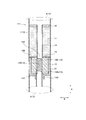
- a method for manufacturing the atomization unit 111 shown in Modification Example 4 (FIG. 9) will be described.
- the attachment method of the atomizing unit housing 111X, the covering member 15, the cap 16, and the flange 17 is substantially the same as that of the embodiment, these attachment methods are omitted.
- a base member 300 (jig) having an axis X extending along a predetermined direction has a first support portion 310 having a first outer diameter and a second outer diameter smaller than the first outer diameter.
- a second support part 320, a base part 330, and a step part 340 are included.
- the inner diameter of the tubular member 14 1 corresponds to the first outer diameter
- the inner diameter of the tubular member 14 2 corresponds to the second outer diameter
- the base portion 330 is a member for supporting the first support portion 310 constitute a first locking portion for locking the tubular member 14 1, the step portion 340, the first support portion 310 and the second a boundary portion between the support portion 320, constituting the second engaging portion for engaging the tubular member 14 2.
- the inner diameter of the tubular member 14 1 and corresponds to the first outer diameter, the tubular member 14 1 of the inner side surface along the heating element 13 disposed on the outer side surface of the first support portion 310 slidable, the size of the tubular member 14 1 of the inner diameter as the first support portion heating element 13 disposed in the 310 and the tubular member 14 1 of the inner side is in contact with the outer diameter of the first support portion 310 It means the relationship.
- the cylindrical member 14 2 of the inner diameter corresponds to the second outer diameter
- the cylindrical member 14 2 of the inner side surface along the outer side surface of the second support portion 320 is slidable, tubular member 14 2 There state (e.g., manufacturing process) which is arranged outside the side surface of the second support portion 320 the tubular member 14 and second central axes inside diameter of a cylindrical member 14 2 not displaced from the center axis of the second support portion 320 in the And the outer diameter of the second support part 320.
- the heating element 13 is arranged along the spiral groove or protrusion formed on the outer side surface of the first support portion 310 (step A).
- the tubular member 14 1 along the axis X by the base portion 330 to a position where the tubular member 14 1 is locked by sliding, the first support portion 310 placing the tubular member 14 1 along the outward side (steps E1 and step E3).
- the step shown in FIG. 12 (B) is a step of placing the tubular member 14 1 toward the first support portion 310 side having a larger outer diameter from the second support portion 320 side having a smaller outer diameter.
- the overall length of the tubular member 14 1 it should be noted that less than the entire length of the first support portion 310.
- Step shown in FIG. 12 (C) is a step of placing the tubular member 14 2 toward the first support portion 310 side having a larger outer diameter from the second support portion 320 side having a smaller outer diameter.
- Tubular member 14 2 It should be noted that to be locked at the step portion 340. Thus, the tubular member 14 1 and the cylindrical member 14 2 is disposed apart from each other.
- Second contact CP2 constituting the second contact point CP2 by connecting a lead wire drawn from the heated portion 13A to the upstream to the exterior side surface of the tubular member 14 2.
- lead is fixed to the outer side surface of the tubular member 14 2 by welding or soldering.
- Second contact CP2 may be configured by connecting a lead wire to the end face of the cylindrical member 14 2.
- the liquid holding member 12 is disposed on the outer side surfaces of the heating element 13 and the cylindrical member 14. That is, the liquid holding member 12 is arranged so as to be in contact with or close to the heating portion 13A of the heating element 13 (step C).
- the step of arranging the liquid holding member 12 so as to be in contact with or close to the heating portion 13A of the heating element 13 is performed on the first support portion 310 side having a large outer diameter from the second support portion 320 side having a small outer diameter. This is a step of disposing the liquid holding member 12 toward the surface.
- the base member 300 (jig) is rotated about the axis X as a rotation axis, and all of the heating elements 13 are separated from the grooves or protrusions of the base member 300 (step B).
- the aerosol inlet and the air flow path are formed by the process shown in FIG.
- the tubular member 14 similarly to the embodiment, via a cap 16 and flange 17, the atomizing unit housing 111X (housing cap member 111X 1 and housing cylinder 111X 2) It is preferably fixed. That is, the step shown in FIG. 12E is preferably performed after the cylindrical member 14 is fixed to the atomizing unit housing 111X.
- the lead wire is inflated for convenience of illustration, but it should be noted that the lead wire is actually disposed between the liquid holding member 12 and the cylindrical member 14.
- the tubular member 14 1 is locked by the base portion 330, the tubular member 14 2 is locked by the stepped portion 340. Therefore, it is easy to position the tubular member 14 1 and the cylindrical member 14 2, together easily spaced distance the tubular member 14 1 and the cylindrical member 14 2 corresponding to the heated portion 13A.
- the cylindrical member 14 1 , the cylindrical member 14 2, and the liquid holding member 12 are slid from the second support portion 320 having a small outer diameter toward the first support portion 310 having a large outer diameter. . Therefore, it is easy to slide these members.
- Modification Example 8 of the embodiment will be described. In the following description, differences from Modification 7 will be mainly described.
- Modification Example 8 describes a method for manufacturing the atomization unit 111 shown in Modification Example 5 (FIG. 10). However, since the attachment method of the atomizing unit housing 111X, the covering member 15, the cap 16, and the flange 17 is substantially the same as that of the embodiment, these attachment methods are omitted. In the modified example 8, the same base member 300 (jig) as the modified example 7 is used.
- the inner diameter of the tubular member 14 1 and corresponds to the first outer diameter, the tubular member 14 1 of the inner side surface along the heating element 13 disposed on the outer side surface of the first support portion 310 slidable, the size of the tubular member 14 1 of the inner diameter as the first support portion heating element 13 disposed in the 310 and the tubular member 14 1 of the inner side is in contact with the outer diameter of the first support portion 310 It means the relationship.
- the inner diameter of the tubular member 14 2 is the corresponding second outer diameter
- the cylindrical member 14 2 along the heating element 13 disposed on the outer side surface of the second support portion 320 is slidable, the means the magnitude of the relationship between the second support portion 320 arranged heating element 13 and the tubular member 14 2 of the inner diameter of the cylindrical member 14 2, such as the inner side is in contact with the outer diameter of the second support portion 320 .
- the heating element 13 is disposed along the spiral groove or protrusion formed on the outer side surface of the first support portion 310 and the outer side surface of the second support portion 320 (step A). ).
- FIG. 13 (B) the by sliding the tubular member 14 1 along the axis X by the base portion 330 to a position where the tubular member 14 1 is locked, the first support portion 310 placing the tubular member 14 1 along the outward side (steps E1 and step E3).
- step portion 340 by positioning the slide cylindrical member 14 2 along the axis X to the tubular member 14 2 by the step portion 340 is engaged, the second support portion 320 placing the tubular member 14 2 along the outside side (steps E2 and step E4). Subsequently, the liquid holding member 12 is arranged on the outer side surfaces of the heating element 13 and the cylindrical member 14 by sliding the liquid holding member 12 along the axis X.
- the base member 300 (jig) is rotated about the axis X as a rotation axis, and all the heating elements 13 are separated from the grooves or protrusions of the base member 300 (step B).
- the point that the aerosol inlet and the air flow path are formed by the process shown in FIG. 13D is the same as in the embodiment.
- the cylindrical member 14 1 , the cylindrical member 14 2, and the liquid holding member 12 are slid from the second support portion 320 side having a small outer diameter toward the first support portion 310 side having a large outer diameter. . Therefore, it is easy to slide these members.
- Modification Example 9 of the embodiment will be described. In the following description, differences from Modification 7 will be mainly described.
- Modification 9 a method for manufacturing the atomization unit 111 shown in Modification 6 (FIG. 11) will be described. However, since the attachment method of the atomizing unit housing 111X, the covering member 15, the cap 16, and the flange 17 is substantially the same as that of the embodiment, these attachment methods are omitted. In Modification Example 9, the same base member 300 (jig) as in Modification Example 7 is used.
- the inner diameter of the tubular member 14 1 corresponding to the first outer diameter, the tubular member 14 1 of the inner side surface along the outer side surface of the first support portion 310 is slidably tubular state member 14 1 is disposed on the exterior side surface of the first support portion 310 (e.g., the manufacturing process) the tubular member 14 1 of the central axis the tubular member 14 so as not deviated from the center axis of the first support portion 310 in the 1 means the relationship between the inner diameter of the first support portion 310 and the outer diameter of the first support portion 310.
- the inner diameter of the tubular member 14 2 is the corresponding second outer diameter
- the cylindrical member 14 2 of the inner side surface along the outer side surface of the second support portion 320 is slidable, tubular member 14 2 There state (e.g., manufacturing process) which is arranged outside the side surface of the second support portion 320 the tubular member 14 and second central axes inside diameter of a cylindrical member 14 2 not displaced from the center axis of the second support portion 320 in the And the outer diameter of the second support part 320.
- the tubular member 14 1 along the axis X by the base portion 330 to a position where the tubular member 14 1 is locked by sliding the outer side surface of the first support portion 310 placing the tubular member 14 1 along (step E1 and step E3).
- the outer side surface of the tubular member 14 2 does not have an outer side surface and the step of the first support portion 310 It is preferable.
- the outer diameter of the tubular member 14 2 is preferably equal to the outer diameter of the first support portion 310.
- Step A arranging the heating elements 13 on the outer side of the outer side and the cylindrical member 14 2 of the first support portion 310 (Step A).
- a spiral groove or protrusion is provided on the outer side surface of the first support portion 310.
- the grooves or projections of the spiral shape is provided on the outside side surface of the tubular member 14 2, it is preferable that the grooves or projections of the spiral shape is provided.
- the tubular member 14 and second outer sides formed spiral groove or protrusion is preferably continuous with the spiral groove or protrusion formed on the outer side surface of the first support portion 310.
- Step A is a step of placing the first heating element 13 along the outer side and the cylindrical member 14 and second spiral grooves or protrusions formed on the outer side surface of the support portion 310.
- First contact CP1 constituting the first contact point CP1 by connecting a lead wire drawn downstream from the heated portion 13A on the outer side surface of the tubular member 14 1.
- lead is fixed to the outer side surface of the tubular member 14 1 by welding or soldering.
- First contact CP1 may be configured by connecting a lead wire to the end face of the tubular member 14 1.
- the liquid holding member 12 is disposed on the outer side surfaces of the heating element 13 and the cylindrical member 14. That is, the liquid holding member 12 is arranged so as to be in contact with or close to the heating portion 13A of the heating element 13 (step C).
- the base member 300 (jig) is rotated about the axis X as a rotation axis, and all of the heating elements 13 are separated from the grooves or protrusions of the base member 300 (step B).
- the point that the aerosol inlet and the air flow path are formed by the process shown in FIG. 14E is the same as in the embodiment.
- the lead wire is inflated for convenience of illustration, but it should be noted that actually the lead wire is disposed between the liquid holding member 12 and the cylindrical member 14.
- the tubular member 14 1 is locked by the base portion 330, the tubular member 14 2 is locked by the stepped portion 340. Therefore, it is easy to position the tubular member 14 1 and the cylindrical member 14 2, together easily spaced distance the tubular member 14 1 and the cylindrical member 14 2 corresponding to the heated portion 13A.
- the cylindrical member 14 1 , the cylindrical member 14 2, and the liquid holding member 12 are slid from the second support portion 320 side having a small outer diameter toward the first support portion 310 side having a large outer diameter. . Therefore, it is easy to slide these members.
- a heating element 13 along the outer side and the cylindrical member 14 is formed on the second outer side surface a spiral groove or protrusion of the first support portion 310.
- Modification Example 10 of the embodiment will be described. In the following, differences from the embodiment will be mainly described.
- the flange 17 1 is disposed at the downstream end surface of the cap 16.
- the lead wire 18 extending from the first pole of the power source is connected to the inner side of the tubular member 14 1
- the Lead 18 may be directed into the tubular member 14 1 through the atomizing unit housing 111X.
- the lead wire 18 is provided downstream of the cap 16 in the separation direction, which is the direction in which the cap 16 is separated from the reservoir 11. In other words, when the cap 16 is separated from the reservoir 11, the lead wire 18 is caught on the cap 16. Accordingly, since the lead wire 18 is pulled by the cap 16, the peeling of the lead wire 18 from the tubular member 14 1, disconnection of the lead wire 18, or, due to the fact that the tubular member 14 1 is pulled by the lead 18 The heating element 13 is deformed.
- the cap 16 is fixed or fitted in the tubular member 14 1. Therefore, an attempt to separate the cap 16 from the reservoir 11, the deformation of the heating member 13 due to the tubular member 14 1 is pulled occurs.
- the lead wire 18 is provided downstream of the cap 16 in the separation direction, which is the direction in which the cap 16 is separated from the reservoir 11. Therefore, when the cap 16 is separated from the reservoir 11, the heating element 13 and the power supply member are damaged, and therefore the use of the flavor inhaler 100 accompanied by reinjection of the aerosol source to the reservoir 11 can be effectively suppressed. .
- the flange 17 1 is disposed at the downstream end surface of the cap 16.
- the flange 17 1 as shown in FIG. 16, it is arranged on the upstream end face of the cap 16.
- the flange 17 1, lead 18 extending from the first pole of the power supply is connected. Lead 18 may be directed to the flange 17 1 passes through the inside of the cap 16.
- the inlet 112A is provided in the electrical unit housing 112X, the liquid holding member 12 is disposed on the outer side surface of the cylindrical member 14, and the cylindrical member 14 forms an air flow path.
- the inlet 112A is provided in the atomizing unit housing 111X, the liquid holding member 12 is disposed inside the tubular member 14, and the air flow is disposed outside the tubular member 14. A path is formed.
- the atomization unit 111 includes a reservoir 11, a liquid holding member 12, a heating element 13, and a cylindrical member 14.
- the reservoir 11, the liquid holding member 12, the heating element 13, and the cylindrical member 14 are accommodated in an atomization unit housing 111X having an inlet 112A.
- the liquid holding member 12 has an insertion portion inserted into the tubular member 14 and an exposed portion exposed from the tubular member 14. The insertion portion contacts an aerosol source stored in the reservoir 11. The exposed part swells in the orthogonal direction B more than the insertion part.
- the heating element 13 is disposed across the outer side surface of the cylindrical member 14 and the outer side surface of the exposed portion of the liquid holding member 12.
- the heating element 13 is disposed so as to be in contact with or close to the exposed portion of the liquid holding member 12.
- the air introduced from the inlet 112A is guided downstream through the outer side surfaces of the cylindrical member 14 and the exposed portion of the liquid holding member 12, and the aerosol atomized by the heating element 13 is removed. Deliver downstream.
- the cylindrical member 14 is not composed of a conductive member, and the heating element 13 is connected to a power source by a power supply member such as a lead wire.
- FIG. 18 is a diagram for explaining a method of manufacturing the atomization unit 111 according to the modification example 13. It should be noted that in FIG. 18, the atomizing unit housing 111X, the cap 16, the flange 17, and the like are omitted.
- the heating element 13 extends along a spiral groove or protrusion formed on the outer side surface of the cylindrical member 14 having the axis X extending along the predetermined direction A. Is arranged (step A). Moreover, the cylindrical member 14 and the heat generating body 13 are electrically connected (step D).
- the liquid holding member 12 is disposed inside the cylindrical member 14 in the orthogonal direction B.
- the cylindrical member 14 is rotated about the axis X as a rotation axis, and a part of the heating element 13 is separated from the groove or protrusion of the cylindrical member 14 (step B).
- the heating element 13 is in contact with or close to the heating element 13. In this way, the liquid holding member 12 is arranged (step C).
- a part of the heating element 13 is separated from the cylindrical member 14 by the rotation of the cylindrical member 14, and the liquid holding member 12 disposed inside the cylindrical member 14.
- a part of the liquid holding member 12 is separated from the tubular member 14, and a part of the liquid holding member 12 is brought into contact with or close to a part of the heating element 13 by the expansion of a part of the liquid holding member 12 (Step B and Step C).
- the liquid holding member 12 presses the inner side surface of a part of the heating element 13 (heating part 13A).
- the liquid holding member 12 is disposed.
- the step shown in FIG. 18B is a step of disposing the liquid holding member 12 so as to be in contact with the entire circumference of the inner side surface of a part of the heating element 13 (heating portion 13A).
- the liquid holding member 12 does not move along the predetermined direction A as the cylindrical member 14 rotates. It should be noted that it is preferable to fix at least the liquid holding member 12.
- the counterpart to fix the liquid holding member 12 may be any member that does not move with the rotation of the cylindrical member 14.
- the liquid holding member 12 in the state where the liquid holding member 12 is disposed inside the cylindrical member 14, a part of the heating element 13 is separated from the groove or the protrusion of the cylindrical member 14,
- the liquid holding member 12 may be disposed so as to be in contact with or close to the heating element 13 after separating a part of the heating element 13 from the groove or the protrusion.
- the liquid holding member 12 in a state where a part of the heating element 13 is separated from the groove or protrusion of the cylindrical member 14, the liquid holding member 12 is directed from the side where the heating element 13 is not provided toward the side where the heating element 13 is provided.
- the exposed portion of the liquid holding member 12 may be brought into contact with or in proximity to the heating element 13 by pushing into the cylindrical member 14.
- the base member 300 that is a jig having a cylindrical shape is not included in the atomization unit 111 as a configuration of the atomization unit 111.
- the base member 300 is included in the atomization unit 111 as a configuration of the atomization unit 111.
- the atomization unit 111 includes a base member 300 having an axis extending along the predetermined direction A and a spiral groove or protrusion formed on the side surface of the base member 300, as shown in FIG. , The heating element 13 arranged along the heating element 13, the liquid holding member 12 that holds the aerosol source, and the heating element 13 and the liquid holding member 12. And at least an atomizing unit housing 111X. At least a part of the base member 300 is preferably exposed from the atomizing unit housing 111X.
- the atomization unit 111 may include other configurations (for example, the reservoir 11, the cylindrical member 14, the covering member 15, the cap 16, the flange 17, and the like) as in the embodiment.
- the base member 300 is used.
- the step of separating the heating element 13 from the groove or the protrusion is performed, for example, when the user who has acquired the atomizing unit 111 uses the atomizing unit 111.
- FIG. 19 illustrates a case in which the base member 300 is a jig, as in the embodiment (for example, FIGS. 4 and 5).
- the modified example 14 is not limited to the example illustrated in FIG.
- the base member 300 as shown in Figure 8 shown in FIG. 7 (A) or third modification of the modification 2 (A), even in the tubular member 14 (the tubular member 14 1 and the cylindrical member 14 2) Good.
- the liquid holding member 12 contacts or approaches at least a part of the heating element 13 by rotating the cylindrical member 14 about the axis X as a rotation axis to separate the heating element 13 from the groove or the protrusion.
- a part of the cylindrical member 14 is preferably exposed from the atomization unit housing 111X.
- the heating element 13 can be easily separated from the groove or the protrusion by the rotation of the base member 300 before the atomization unit 111 is used.
- the step of housing the heating element 13 and the liquid holding member 12 in the atomizing unit housing 111X is performed in a state where a part of the base member 300 is exposed from the atomizing unit housing 111X.
- the heating element 13 can be easily separated from the groove or the protrusion by the rotation of the base member 300 before the atomization unit 111 is used.
- Modification Example 15 of the embodiment will be described. In the following, differences from the embodiment will be mainly described.
- the reservoir 11 is disposed outside the liquid holding member 12 in the orthogonal direction B.
- the reservoir 11 is arranged side by side with the liquid holding member 12 and the heating element 13 in the predetermined direction A.
- the atomization unit 111 includes a support member 21 in addition to the configuration shown in FIG. As described above, the reservoir 11 is arranged side by side with the liquid holding member 12 and the heating element 13 in the predetermined direction A.
- the support member 21 supports the liquid holding member 12 and the heating element 13.
- the first end portion 13B 1 and the power supply member 13C rather than the wire constituting the heating portion 13A and the electrical resistivity is covered by the lower conductive member, a second end portion 13B 2 and the power supply
- the member 13D is covered with a conductive member having an electric resistivity lower than that of the wire constituting the heating portion 13A.
- the heating portion 13A is not covered with a conductive member having a lower electrical resistivity than the wire constituting the heating portion 13A, and the wire is exposed. According to such a configuration, a portion having good quality other than the end portion of the wire constituting the heating element 13 (coil) can be used as the heating portion 13A.
- first end portion 13B 1 , the second end portion 13B 2 , the power supply member 13C, and the power supply member 13D are the same wires as the wires constituting the heating portion 13A and are conductive members having a lower electrical resistivity than the wires. Is preferably coated. With such a configuration, it is easy to integrally manufacture the first end portion 13B 1 , the second end portion 13B 2 , the power supply member 13C, the power supply member 13D, and the heating portion 13A with good quality. Become.
- the wire is made of a nickel chrome alloy
- a metal having a lower electrical resistivity than a nickel chrome alloy such as copper, tin, or silver can be used as the conductive member.
- the atomization unit 111 has a liquid amount adjusting member 19 as shown in FIG.
- the liquid amount adjusting member 19 has an opening 19A and an opening 19B, and is a member having, for example, a disk shape.
- the opening 19 ⁇ / b> A is an opening for forming an air flow path, and is an opening that communicates the inside of the tubular member 14 and the inside of the heating element 13.
- the opening 19 ⁇ / b> B is an opening for supplying an aerosol source from the reservoir 11 to the liquid holding member 12, and is an opening for communicating the reservoir 11 and the liquid holding member 12.
- the reservoir 11 may be a cavity for storing an aerosol source.
- the aerosol source stored in the reservoir 11 is supplied to the liquid holding member 12 through the opening 19 ⁇ / b> B of the liquid amount adjusting member 19.
- the aerosol source supplied to the liquid holding member 12 moves to a position in contact with or close to the heating portion 13A by expanding into the liquid holding member 12 by capillary action. Thereby, the aerosol source is atomized by the heating portion 13A. Therefore, the liquid holding member 12 is considered to be a member that moves the aerosol source from the reservoir 11 to the liquid holding member 12 by capillary action.
- the first end portion 13B 1 and the power supply member 13C rather than the wire constituting the heating portion 13A and the electrical resistivity is covered by the lower conductive member, a second end portion 13B 2 and the power supply The member 13D is covered with a conductive member having an electric resistivity lower than that of the wire constituting the heating portion 13A.
- the modified example 15 is not limited to this.
- the first end portion 13B 1 and the power supply member 13C may be constituted by a conductive member electrical resistivity is lower than the heating portion 13A.
- the second end portion 13B 2 and the power supply member 13D may be constituted by a conductive member electrical resistivity is lower than the heating portion 13A.
- FIG. 22 is a diagram for explaining a method for manufacturing the atomization unit 111 according to the sixteenth modification.
- the heating element 13 is arranged along a spiral groove or protrusion formed on the side surface of a base member 300 (jig) having an axis X extending along a predetermined direction A. (Step A). Subsequently, the liquid holding member 12 is disposed so as to be in contact with or close to at least a part of the heating element 13 (step C).
- the liquid holding member 12 may be arranged in a state of being incorporated in the support member 21, and the support member 21 may be arranged after the liquid holding member 12 is arranged.
- the base member 300 (jig) is rotated about the axis X as the rotation axis, and the heating element 13 Are all separated from the grooves or protrusions of the base member 300 (step B).
- a reservoir 11, a cylindrical member 14, a cap 16, a liquid amount adjusting member 19, and an atomizing unit housing 111X are arranged.
- a step (step G) of arranging a member (flow path forming member) that forms at least a part of the air flow path is preferably performed.
- the liquid holding member 14 corresponds to the flow path forming member.
- the step shown in FIG. 22A includes the step of arranging the flow path forming member (liquid holding member 12) along the base member 300.
- the heating element 13 may be separated from the base member 300 after the reservoir 11, the cylindrical member 14, the cap 16, the liquid amount adjusting member 19, and the atomizing unit housing 111X are arranged.
- the cylindrical member 14 corresponds to the flow path forming member in addition to the liquid holding member 14.
- the reservoir 11 is disposed outside the liquid holding member 12 in the orthogonal direction B.
- the reservoir 11 only needs to be in contact with the liquid holding member 12 and may not be disposed outside the liquid holding member 12 in the orthogonal direction B.
- the covering member 15 is unexpectedly before the flavor suction device 100 is used or while the flavor suction device 100 is used. It is possible to prevent the aerosol source leaking from the reservoir 11 from being supplied to the liquid holding member 12 from the outer peripheral surface of the liquid holding member 12.
- the liquid holding member 12 has a cylindrical shape. However, the embodiment is not limited to this.
- the liquid holding member 12 may have a string shape.
- members such as the liquid holding member 12 and the covering member 15 have a cylindrical shape, and are arranged outside the heating element 13 by sliding along a predetermined direction A.
- Members such as the liquid holding member 12 and the covering member 15 have a sheet-like shape and may be wound around the heating element 13.
- the supply port for supplying the aerosol source to the reservoir 11 is provided at the downstream end of the reservoir 11, and the cap 16 closes the downstream end of the reservoir 11.
- the supply port may be provided at the upstream end of the reservoir 11, and the cap 16 may block the upstream end of the reservoir 11.
- the heating element 13 is a coil having a shape extending along the predetermined direction A, which is formed of a wire having a spiral shape, and the inside of the heating element 13 is hollow.
- the inside of the heating element 13 may be solid.
- the liquid holding member 12 may be provided inside the heating element 13.
- the heating element 13 is formed by a wire having a spiral shape.
- the heating element 13 may be configured by a conductive member having another shape.
- the cylindrical member 14 forming at least a part of the air flow path is formed of a conductive member.
- the cylindrical member 14 may be configured by a member other than the conductive member.
- a lead wire 18 is provided as a member for connecting the power source and the cylindrical member 14.
- the member for connecting the power source and the cylindrical member 14 may constitute an electrical path, and may be a part of the housing constituting the flavor inhaler 100 or the like.
- the outer diameter of the tubular member 14 1 is larger than the outer diameter of the tubular member 14 2.
- the embodiment is not limited to this.
- the outer diameter of the tubular member 14 1 may be equal to the outer diameter of the tubular member 14 2.
- the inner diameter of the tubular member 14 1 is larger than the inner diameter of the tubular member 14 2, when the outside diameter of the tubular member 14 1 is equal to the outer diameter of the tubular member 14 2, the tubular member 14 2 the thickness is should be noted that greater than the tubular member 14 1 thickness.
- the fixing method of each member may be adhesion or welding.
- the liquid holding member 12 is configured by, for example, a sponge-like elastic member, and expands when the sliding member 400 and the cylindrical member 14 that have compressed the liquid holding member 12 are removed,
- the structure which contacts or adjoins the heat generating body 13 may be sufficient.
Priority Applications (3)
| Application Number | Priority Date | Filing Date | Title |
|---|---|---|---|
| CN201680043800.9A CN107920590B (zh) | 2015-06-26 | 2016-06-24 | 雾化单元 |
| EP16814528.2A EP3315036A4 (en) | 2015-06-26 | 2016-06-24 | ATOMIZATION UNIT |
| HK18109567.4A HK1250134A1 (zh) | 2015-06-26 | 2018-07-24 | 霧化單元 |
Applications Claiming Priority (2)
| Application Number | Priority Date | Filing Date | Title |
|---|---|---|---|
| JPPCT/JP2015/068580 | 2015-06-26 | ||
| JP2015068580 | 2015-06-26 |
Publications (1)
| Publication Number | Publication Date |
|---|---|
| WO2016208759A1 true WO2016208759A1 (ja) | 2016-12-29 |
Family
ID=57585171
Family Applications (1)
| Application Number | Title | Priority Date | Filing Date |
|---|---|---|---|
| PCT/JP2016/068932 WO2016208759A1 (ja) | 2015-06-26 | 2016-06-24 | 霧化ユニット |
Country Status (5)
| Country | Link |
|---|---|
| EP (1) | EP3315036A4 (zh) |
| CN (1) | CN107920590B (zh) |
| HK (1) | HK1250134A1 (zh) |
| TW (1) | TWI642367B (zh) |
| WO (1) | WO2016208759A1 (zh) |
Cited By (5)
| Publication number | Priority date | Publication date | Assignee | Title |
|---|---|---|---|---|
| JP2021505128A (ja) * | 2017-12-06 | 2021-02-18 | ニコベンチャーズ トレーディング リミテッド | エアロゾル生成装置のためのコンポーネント |
| US20210068458A1 (en) * | 2018-05-18 | 2021-03-11 | Nerudia Ltd | Consumable for a smoking substitute device |
| US11318264B2 (en) | 2017-01-13 | 2022-05-03 | Nicoventures Trading Limited | Aerosol generating device and article |
| US11589617B2 (en) | 2017-01-05 | 2023-02-28 | Nicoventures Trading Limited | Aerosol generating device and article |
| JP7346381B2 (ja) | 2017-08-11 | 2023-09-19 | フィリップ・モーリス・プロダクツ・ソシエテ・アノニム | ベイパー挿入部 |
Citations (5)
| Publication number | Priority date | Publication date | Assignee | Title |
|---|---|---|---|---|
| JPS56144496U (zh) * | 1980-03-31 | 1981-10-31 | ||
| JP3413208B2 (ja) * | 1996-06-17 | 2003-06-03 | 日本たばこ産業株式会社 | 香味生成物品及び香味生成器具 |
| JP2007335386A (ja) * | 2006-06-19 | 2007-12-27 | Aun:Kk | ヒーターランプの端子 |
| JP2011087569A (ja) * | 2009-05-15 | 2011-05-06 | Jbs:Kk | 電子タバコ、および充電ユニット |
| WO2014058678A1 (en) * | 2012-10-08 | 2014-04-17 | R. J. Reynolds Tobacco Company | An electronic smoking article and associated method |
Family Cites Families (8)
| Publication number | Priority date | Publication date | Assignee | Title |
|---|---|---|---|---|
| EP2113178A1 (en) * | 2008-04-30 | 2009-11-04 | Philip Morris Products S.A. | An electrically heated smoking system having a liquid storage portion |
| CN101843368A (zh) * | 2010-04-02 | 2010-09-29 | 陈志平 | 电子雾化吸入器的吸嘴 |
| CN201830900U (zh) * | 2010-06-09 | 2011-05-18 | 李永海 | 电子香烟的烟液雾化装置 |
| US9301549B2 (en) * | 2013-01-08 | 2016-04-05 | Huizhou Kimree Technology Co., Ltd., Shenzhen Branch | Electronic cigarette device, electronic cigarette and atomization device thereof |
| JP6426142B2 (ja) * | 2013-03-14 | 2018-11-21 | アール・ジエイ・レイノルズ・タバコ・カンパニー | エアロゾル吐出装置用アトマイザおよび関連する製造材、エアロゾル発生アセンブリ、カートリッジおよび方法 |
| CN203537580U (zh) * | 2013-11-19 | 2014-04-09 | 刘秋明 | 电子烟、雾化器及其发热丝的连接端子 |
| CN204191592U (zh) * | 2014-10-21 | 2015-03-11 | 朱晓春 | 一种电子烟雾化器发热组件 |
| CN204377939U (zh) * | 2015-01-27 | 2015-06-10 | 深圳市腾烟科技有限公司 | 一种具有密封储油功能的电子烟雾化器 |
-
2016
- 2016-06-24 WO PCT/JP2016/068932 patent/WO2016208759A1/ja active Application Filing
- 2016-06-24 CN CN201680043800.9A patent/CN107920590B/zh active Active
- 2016-06-24 EP EP16814528.2A patent/EP3315036A4/en not_active Withdrawn
- 2016-06-27 TW TW105120148A patent/TWI642367B/zh active
-
2018
- 2018-07-24 HK HK18109567.4A patent/HK1250134A1/zh unknown
Patent Citations (5)
| Publication number | Priority date | Publication date | Assignee | Title |
|---|---|---|---|---|
| JPS56144496U (zh) * | 1980-03-31 | 1981-10-31 | ||
| JP3413208B2 (ja) * | 1996-06-17 | 2003-06-03 | 日本たばこ産業株式会社 | 香味生成物品及び香味生成器具 |
| JP2007335386A (ja) * | 2006-06-19 | 2007-12-27 | Aun:Kk | ヒーターランプの端子 |
| JP2011087569A (ja) * | 2009-05-15 | 2011-05-06 | Jbs:Kk | 電子タバコ、および充電ユニット |
| WO2014058678A1 (en) * | 2012-10-08 | 2014-04-17 | R. J. Reynolds Tobacco Company | An electronic smoking article and associated method |
Non-Patent Citations (1)
| Title |
|---|
| See also references of EP3315036A4 * |
Cited By (6)
| Publication number | Priority date | Publication date | Assignee | Title |
|---|---|---|---|---|
| US11589617B2 (en) | 2017-01-05 | 2023-02-28 | Nicoventures Trading Limited | Aerosol generating device and article |
| US11318264B2 (en) | 2017-01-13 | 2022-05-03 | Nicoventures Trading Limited | Aerosol generating device and article |
| JP7346381B2 (ja) | 2017-08-11 | 2023-09-19 | フィリップ・モーリス・プロダクツ・ソシエテ・アノニム | ベイパー挿入部 |
| JP2021505128A (ja) * | 2017-12-06 | 2021-02-18 | ニコベンチャーズ トレーディング リミテッド | エアロゾル生成装置のためのコンポーネント |
| US11623053B2 (en) | 2017-12-06 | 2023-04-11 | Nicoventures Trading Limited | Component for an aerosol-generating apparatus |
| US20210068458A1 (en) * | 2018-05-18 | 2021-03-11 | Nerudia Ltd | Consumable for a smoking substitute device |
Also Published As
| Publication number | Publication date |
|---|---|
| EP3315036A1 (en) | 2018-05-02 |
| EP3315036A4 (en) | 2019-01-23 |
| CN107920590B (zh) | 2021-02-26 |
| CN107920590A (zh) | 2018-04-17 |
| TWI642367B (zh) | 2018-12-01 |
| TW201705871A (zh) | 2017-02-16 |
| HK1250134A1 (zh) | 2018-11-30 |
Similar Documents
| Publication | Publication Date | Title |
|---|---|---|
| JP6752928B2 (ja) | 霧化ユニット | |
| JP6752939B2 (ja) | 霧化ユニット | |
| WO2016208760A1 (ja) | 霧化ユニットの製造方法及び霧化ユニット | |
| WO2016208759A1 (ja) | 霧化ユニット | |
| EP3610749B1 (en) | Apparatus for an aerosol provision system, and electronic aerosol provision system | |
| US20170105455A1 (en) | Atomizer and aerosol generating device thereof | |
| EP3287017A1 (en) | Atomizer and aerosol generation device thereof | |
| CN105916399B (zh) | 用于气溶胶生成系统的筒 | |
| JP7257359B2 (ja) | エアロゾル発生システムのためのカートリッジ | |
| JP2022519511A (ja) | 蒸気供給システム | |
| EP3742909A1 (en) | Vapour provision system | |
| WO2020183521A1 (ja) | 吸引器用カートリッジおよびこれを備えた吸引器 |
Legal Events
| Date | Code | Title | Description |
|---|---|---|---|
| 121 | Ep: the epo has been informed by wipo that ep was designated in this application |
Ref document number: 16814528 Country of ref document: EP Kind code of ref document: A1 |
|
| NENP | Non-entry into the national phase |
Ref country code: DE |
|
| WWE | Wipo information: entry into national phase |
Ref document number: 2016814528 Country of ref document: EP |
|
| NENP | Non-entry into the national phase |
Ref country code: JP |