WO2016208715A1 - Method for producing ultraviolet protective agent composition, and ultraviolet protective agent composition obtained thereby - Google Patents
Method for producing ultraviolet protective agent composition, and ultraviolet protective agent composition obtained thereby Download PDFInfo
- Publication number
- WO2016208715A1 WO2016208715A1 PCT/JP2016/068806 JP2016068806W WO2016208715A1 WO 2016208715 A1 WO2016208715 A1 WO 2016208715A1 JP 2016068806 W JP2016068806 W JP 2016068806W WO 2016208715 A1 WO2016208715 A1 WO 2016208715A1
- Authority
- WO
- WIPO (PCT)
- Prior art keywords
- iron oxide
- processing surface
- fluid
- fine particles
- oxide fine
- Prior art date
Links
- 239000000203 mixture Substances 0.000 title claims abstract description 71
- 238000004519 manufacturing process Methods 0.000 title claims abstract description 46
- 239000003223 protective agent Substances 0.000 title claims abstract description 12
- UQSXHKLRYXJYBZ-UHFFFAOYSA-N Iron oxide Chemical compound [Fe]=O UQSXHKLRYXJYBZ-UHFFFAOYSA-N 0.000 claims abstract description 516
- 239000012530 fluid Substances 0.000 claims abstract description 189
- 239000006185 dispersion Substances 0.000 claims abstract description 80
- 239000002994 raw material Substances 0.000 claims abstract description 57
- 230000001681 protective effect Effects 0.000 claims abstract description 42
- 238000002834 transmittance Methods 0.000 claims abstract description 33
- 238000001556 precipitation Methods 0.000 claims abstract description 20
- 239000000126 substance Substances 0.000 claims abstract description 20
- 239000002612 dispersion medium Substances 0.000 claims abstract description 11
- 238000012545 processing Methods 0.000 claims description 193
- 239000010419 fine particle Substances 0.000 claims description 143
- 238000003756 stirring Methods 0.000 claims description 49
- 230000008033 biological extinction Effects 0.000 claims description 34
- XEEYBQQBJWHFJM-UHFFFAOYSA-N iron Substances [Fe] XEEYBQQBJWHFJM-UHFFFAOYSA-N 0.000 claims description 34
- 239000011164 primary particle Substances 0.000 claims description 34
- 238000000034 method Methods 0.000 claims description 32
- 239000013078 crystal Substances 0.000 claims description 24
- 239000011163 secondary particle Substances 0.000 claims description 18
- 239000010409 thin film Substances 0.000 claims description 15
- 230000006750 UV protection Effects 0.000 claims description 14
- 238000009835 boiling Methods 0.000 claims description 14
- 238000002156 mixing Methods 0.000 claims description 14
- 238000013459 approach Methods 0.000 claims description 12
- 150000002500 ions Chemical class 0.000 claims description 12
- 230000008021 deposition Effects 0.000 claims description 9
- 229910052595 hematite Inorganic materials 0.000 claims description 7
- 239000011019 hematite Substances 0.000 claims description 7
- 238000000926 separation method Methods 0.000 claims description 5
- 238000007599 discharging Methods 0.000 claims description 3
- 239000003795 chemical substances by application Substances 0.000 claims description 2
- 239000002609 medium Substances 0.000 claims 1
- -1 Fe3+ ions Chemical class 0.000 abstract description 28
- 239000011859 microparticle Substances 0.000 abstract description 6
- 230000001376 precipitating effect Effects 0.000 abstract description 3
- 239000002245 particle Substances 0.000 description 49
- 230000000052 comparative effect Effects 0.000 description 46
- 238000005259 measurement Methods 0.000 description 41
- 239000007788 liquid Substances 0.000 description 38
- 239000002904 solvent Substances 0.000 description 34
- HEMHJVSKTPXQMS-UHFFFAOYSA-M Sodium hydroxide Chemical compound [OH-].[Na+] HEMHJVSKTPXQMS-UHFFFAOYSA-M 0.000 description 15
- 238000010586 diagram Methods 0.000 description 15
- 238000000411 transmission spectrum Methods 0.000 description 14
- XLYOFNOQVPJJNP-UHFFFAOYSA-N water Substances O XLYOFNOQVPJJNP-UHFFFAOYSA-N 0.000 description 13
- DNIAPMSPPWPWGF-UHFFFAOYSA-N Propylene glycol Chemical compound CC(O)CO DNIAPMSPPWPWGF-UHFFFAOYSA-N 0.000 description 12
- GWEVSGVZZGPLCZ-UHFFFAOYSA-N Titan oxide Chemical compound O=[Ti]=O GWEVSGVZZGPLCZ-UHFFFAOYSA-N 0.000 description 12
- 238000009826 distribution Methods 0.000 description 11
- MVFCKEFYUDZOCX-UHFFFAOYSA-N iron(2+);dinitrate Chemical compound [Fe+2].[O-][N+]([O-])=O.[O-][N+]([O-])=O MVFCKEFYUDZOCX-UHFFFAOYSA-N 0.000 description 10
- 230000007246 mechanism Effects 0.000 description 10
- 238000010521 absorption reaction Methods 0.000 description 8
- 238000000862 absorption spectrum Methods 0.000 description 8
- 239000000047 product Substances 0.000 description 8
- 239000002270 dispersing agent Substances 0.000 description 7
- 229910052742 iron Inorganic materials 0.000 description 7
- 239000000463 material Substances 0.000 description 7
- KFZMGEQAYNKOFK-UHFFFAOYSA-N Isopropanol Chemical compound CC(C)O KFZMGEQAYNKOFK-UHFFFAOYSA-N 0.000 description 6
- 239000003995 emulsifying agent Substances 0.000 description 6
- 238000010008 shearing Methods 0.000 description 6
- 239000004094 surface-active agent Substances 0.000 description 6
- 229910000859 α-Fe Inorganic materials 0.000 description 6
- 206010001497 Agitation Diseases 0.000 description 5
- 238000013019 agitation Methods 0.000 description 5
- 230000000694 effects Effects 0.000 description 5
- LIKBJVNGSGBSGK-UHFFFAOYSA-N iron(3+);oxygen(2-) Chemical compound [O-2].[O-2].[O-2].[Fe+3].[Fe+3] LIKBJVNGSGBSGK-UHFFFAOYSA-N 0.000 description 5
- 239000003973 paint Substances 0.000 description 5
- 238000002360 preparation method Methods 0.000 description 5
- 150000003839 salts Chemical class 0.000 description 5
- 229920000663 Hydroxyethyl cellulose Polymers 0.000 description 4
- DBMJMQXJHONAFJ-UHFFFAOYSA-M Sodium laurylsulphate Chemical compound [Na+].CCCCCCCCCCCCOS([O-])(=O)=O DBMJMQXJHONAFJ-UHFFFAOYSA-M 0.000 description 4
- 239000002585 base Substances 0.000 description 4
- 230000005540 biological transmission Effects 0.000 description 4
- 238000001816 cooling Methods 0.000 description 4
- 239000003960 organic solvent Substances 0.000 description 4
- 239000004408 titanium dioxide Substances 0.000 description 4
- OGIDPMRJRNCKJF-UHFFFAOYSA-N titanium oxide Inorganic materials [Ti]=O OGIDPMRJRNCKJF-UHFFFAOYSA-N 0.000 description 4
- VTLYFUHAOXGGBS-UHFFFAOYSA-N Fe3+ Chemical compound [Fe+3] VTLYFUHAOXGGBS-UHFFFAOYSA-N 0.000 description 3
- 241000542980 Mimidae Species 0.000 description 3
- KWYUFKZDYYNOTN-UHFFFAOYSA-M Potassium hydroxide Chemical compound [OH-].[K+] KWYUFKZDYYNOTN-UHFFFAOYSA-M 0.000 description 3
- ZMANZCXQSJIPKH-UHFFFAOYSA-N Triethylamine Chemical compound CCN(CC)CC ZMANZCXQSJIPKH-UHFFFAOYSA-N 0.000 description 3
- 238000002835 absorbance Methods 0.000 description 3
- 238000006243 chemical reaction Methods 0.000 description 3
- 239000000571 coke Substances 0.000 description 3
- 239000000084 colloidal system Substances 0.000 description 3
- 239000002537 cosmetic Substances 0.000 description 3
- 239000010408 film Substances 0.000 description 3
- 229910010272 inorganic material Inorganic materials 0.000 description 3
- BAUYGSIQEAFULO-UHFFFAOYSA-L iron(2+) sulfate (anhydrous) Chemical compound [Fe+2].[O-]S([O-])(=O)=O BAUYGSIQEAFULO-UHFFFAOYSA-L 0.000 description 3
- PVFSDGKDKFSOTB-UHFFFAOYSA-K iron(3+);triacetate Chemical compound [Fe+3].CC([O-])=O.CC([O-])=O.CC([O-])=O PVFSDGKDKFSOTB-UHFFFAOYSA-K 0.000 description 3
- DRLFMBDRBRZALE-UHFFFAOYSA-N melatonin Chemical compound COC1=CC=C2NC=C(CCNC(C)=O)C2=C1 DRLFMBDRBRZALE-UHFFFAOYSA-N 0.000 description 3
- 229910052751 metal Inorganic materials 0.000 description 3
- 239000002184 metal Substances 0.000 description 3
- 125000005375 organosiloxane group Chemical group 0.000 description 3
- 150000005846 sugar alcohols Polymers 0.000 description 3
- 229920005992 thermoplastic resin Polymers 0.000 description 3
- QGZKDVFQNNGYKY-UHFFFAOYSA-N Ammonia Chemical compound N QGZKDVFQNNGYKY-UHFFFAOYSA-N 0.000 description 2
- CWYNVVGOOAEACU-UHFFFAOYSA-N Fe2+ Chemical class [Fe+2] CWYNVVGOOAEACU-UHFFFAOYSA-N 0.000 description 2
- 239000004354 Hydroxyethyl cellulose Substances 0.000 description 2
- WQDUMFSSJAZKTM-UHFFFAOYSA-N Sodium methoxide Chemical compound [Na+].[O-]C WQDUMFSSJAZKTM-UHFFFAOYSA-N 0.000 description 2
- JAWMENYCRQKKJY-UHFFFAOYSA-N [3-(2,4,6,7-tetrahydrotriazolo[4,5-c]pyridin-5-ylmethyl)-1-oxa-2,8-diazaspiro[4.5]dec-2-en-8-yl]-[2-[[3-(trifluoromethoxy)phenyl]methylamino]pyrimidin-5-yl]methanone Chemical compound N1N=NC=2CN(CCC=21)CC1=NOC2(C1)CCN(CC2)C(=O)C=1C=NC(=NC=1)NCC1=CC(=CC=C1)OC(F)(F)F JAWMENYCRQKKJY-UHFFFAOYSA-N 0.000 description 2
- 150000001491 aromatic compounds Chemical class 0.000 description 2
- 239000012964 benzotriazole Substances 0.000 description 2
- 238000004140 cleaning Methods 0.000 description 2
- 239000011248 coating agent Substances 0.000 description 2
- 238000000576 coating method Methods 0.000 description 2
- 238000004040 coloring Methods 0.000 description 2
- RTZKZFJDLAIYFH-UHFFFAOYSA-N ether Substances CCOCC RTZKZFJDLAIYFH-UHFFFAOYSA-N 0.000 description 2
- SZVJSHCCFOBDDC-UHFFFAOYSA-N ferrosoferric oxide Chemical compound O=[Fe]O[Fe]O[Fe]=O SZVJSHCCFOBDDC-UHFFFAOYSA-N 0.000 description 2
- 238000009472 formulation Methods 0.000 description 2
- 150000002366 halogen compounds Chemical class 0.000 description 2
- 229940071826 hydroxyethyl cellulose Drugs 0.000 description 2
- 235000019447 hydroxyethyl cellulose Nutrition 0.000 description 2
- 230000001771 impaired effect Effects 0.000 description 2
- 239000011147 inorganic material Substances 0.000 description 2
- 239000002608 ionic liquid Substances 0.000 description 2
- FBAFATDZDUQKNH-UHFFFAOYSA-M iron chloride Chemical compound [Cl-].[Fe] FBAFATDZDUQKNH-UHFFFAOYSA-M 0.000 description 2
- 229910000358 iron sulfate Inorganic materials 0.000 description 2
- RBTARNINKXHZNM-UHFFFAOYSA-K iron trichloride Chemical compound Cl[Fe](Cl)Cl RBTARNINKXHZNM-UHFFFAOYSA-K 0.000 description 2
- SZQUEWJRBJDHSM-UHFFFAOYSA-N iron(3+);trinitrate;nonahydrate Chemical compound O.O.O.O.O.O.O.O.O.[Fe+3].[O-][N+]([O-])=O.[O-][N+]([O-])=O.[O-][N+]([O-])=O SZQUEWJRBJDHSM-UHFFFAOYSA-N 0.000 description 2
- NPFOYSMITVOQOS-UHFFFAOYSA-K iron(III) citrate Chemical compound [Fe+3].[O-]C(=O)CC(O)(CC([O-])=O)C([O-])=O NPFOYSMITVOQOS-UHFFFAOYSA-K 0.000 description 2
- 239000012046 mixed solvent Substances 0.000 description 2
- 125000000896 monocarboxylic acid group Chemical group 0.000 description 2
- 239000002105 nanoparticle Substances 0.000 description 2
- 229940031182 nanoparticles iron oxide Drugs 0.000 description 2
- 238000006386 neutralization reaction Methods 0.000 description 2
- 230000003287 optical effect Effects 0.000 description 2
- 239000011368 organic material Substances 0.000 description 2
- NDLPOXTZKUMGOV-UHFFFAOYSA-N oxo(oxoferriooxy)iron hydrate Chemical compound O.O=[Fe]O[Fe]=O NDLPOXTZKUMGOV-UHFFFAOYSA-N 0.000 description 2
- 230000002093 peripheral effect Effects 0.000 description 2
- 229920000642 polymer Polymers 0.000 description 2
- 238000011084 recovery Methods 0.000 description 2
- 238000011160 research Methods 0.000 description 2
- 229920005989 resin Polymers 0.000 description 2
- 239000011347 resin Substances 0.000 description 2
- 239000011342 resin composition Substances 0.000 description 2
- 239000002002 slurry Substances 0.000 description 2
- 239000006228 supernatant Substances 0.000 description 2
- 239000008399 tap water Substances 0.000 description 2
- 235000020679 tap water Nutrition 0.000 description 2
- 229910021642 ultra pure water Inorganic materials 0.000 description 2
- 239000011882 ultra-fine particle Substances 0.000 description 2
- 239000012498 ultrapure water Substances 0.000 description 2
- 238000005406 washing Methods 0.000 description 2
- BFSVOASYOCHEOV-UHFFFAOYSA-N 2-diethylaminoethanol Chemical compound CCN(CC)CCO BFSVOASYOCHEOV-UHFFFAOYSA-N 0.000 description 1
- PNEYBMLMFCGWSK-UHFFFAOYSA-N Alumina Chemical compound [O-2].[O-2].[O-2].[Al+3].[Al+3] PNEYBMLMFCGWSK-UHFFFAOYSA-N 0.000 description 1
- QGZKDVFQNNGYKY-UHFFFAOYSA-O Ammonium Chemical compound [NH4+] QGZKDVFQNNGYKY-UHFFFAOYSA-O 0.000 description 1
- WPYMKLBDIGXBTP-UHFFFAOYSA-N Benzoic acid Natural products OC(=O)C1=CC=CC=C1 WPYMKLBDIGXBTP-UHFFFAOYSA-N 0.000 description 1
- 239000005711 Benzoic acid Substances 0.000 description 1
- OKTJSMMVPCPJKN-UHFFFAOYSA-N Carbon Chemical compound [C] OKTJSMMVPCPJKN-UHFFFAOYSA-N 0.000 description 1
- 229910002554 Fe(NO3)3·9H2O Inorganic materials 0.000 description 1
- 229910002588 FeOOH Inorganic materials 0.000 description 1
- DGAQECJNVWCQMB-PUAWFVPOSA-M Ilexoside XXIX Chemical compound C[C@@H]1CC[C@@]2(CC[C@@]3(C(=CC[C@H]4[C@]3(CC[C@@H]5[C@@]4(CC[C@@H](C5(C)C)OS(=O)(=O)[O-])C)C)[C@@H]2[C@]1(C)O)C)C(=O)O[C@H]6[C@@H]([C@H]([C@@H]([C@H](O6)CO)O)O)O.[Na+] DGAQECJNVWCQMB-PUAWFVPOSA-M 0.000 description 1
- 239000005569 Iron sulphate Substances 0.000 description 1
- 229910021578 Iron(III) chloride Inorganic materials 0.000 description 1
- GRYLNZFGIOXLOG-UHFFFAOYSA-N Nitric acid Chemical compound O[N+]([O-])=O GRYLNZFGIOXLOG-UHFFFAOYSA-N 0.000 description 1
- XUIMIQQOPSSXEZ-UHFFFAOYSA-N Silicon Chemical compound [Si] XUIMIQQOPSSXEZ-UHFFFAOYSA-N 0.000 description 1
- 229910000831 Steel Inorganic materials 0.000 description 1
- 238000002441 X-ray diffraction Methods 0.000 description 1
- 230000001133 acceleration Effects 0.000 description 1
- 239000002253 acid Substances 0.000 description 1
- 239000012190 activator Substances 0.000 description 1
- 229910052783 alkali metal Inorganic materials 0.000 description 1
- 150000001340 alkali metals Chemical class 0.000 description 1
- 229910021529 ammonia Inorganic materials 0.000 description 1
- 239000003945 anionic surfactant Substances 0.000 description 1
- 235000010233 benzoic acid Nutrition 0.000 description 1
- 229910052799 carbon Inorganic materials 0.000 description 1
- 239000004359 castor oil Substances 0.000 description 1
- 235000019438 castor oil Nutrition 0.000 description 1
- 239000003093 cationic surfactant Substances 0.000 description 1
- 239000000919 ceramic Substances 0.000 description 1
- 150000001875 compounds Chemical class 0.000 description 1
- 230000007423 decrease Effects 0.000 description 1
- HPNMFZURTQLUMO-UHFFFAOYSA-N diethylamine Chemical compound CCNCC HPNMFZURTQLUMO-UHFFFAOYSA-N 0.000 description 1
- 238000007865 diluting Methods 0.000 description 1
- 238000011156 evaluation Methods 0.000 description 1
- 239000011640 ferrous citrate Substances 0.000 description 1
- 235000019850 ferrous citrate Nutrition 0.000 description 1
- 230000014509 gene expression Effects 0.000 description 1
- 239000011521 glass Substances 0.000 description 1
- ZEMPKEQAKRGZGQ-XOQCFJPHSA-N glycerol triricinoleate Natural products CCCCCC[C@@H](O)CC=CCCCCCCCC(=O)OC[C@@H](COC(=O)CCCCCCCC=CC[C@@H](O)CCCCCC)OC(=O)CCCCCCCC=CC[C@H](O)CCCCCC ZEMPKEQAKRGZGQ-XOQCFJPHSA-N 0.000 description 1
- 229910052598 goethite Inorganic materials 0.000 description 1
- 230000005484 gravity Effects 0.000 description 1
- 150000004677 hydrates Chemical class 0.000 description 1
- AEIXRCIKZIZYPM-UHFFFAOYSA-M hydroxy(oxo)iron Chemical compound [O][Fe]O AEIXRCIKZIZYPM-UHFFFAOYSA-M 0.000 description 1
- 150000002484 inorganic compounds Chemical class 0.000 description 1
- JEIPFZHSYJVQDO-UHFFFAOYSA-N iron(III) oxide Inorganic materials O=[Fe]O[Fe]=O JEIPFZHSYJVQDO-UHFFFAOYSA-N 0.000 description 1
- 229910000462 iron(III) oxide hydroxide Inorganic materials 0.000 description 1
- 230000007774 longterm Effects 0.000 description 1
- 239000012567 medical material Substances 0.000 description 1
- 150000002736 metal compounds Chemical class 0.000 description 1
- 229910000000 metal hydroxide Inorganic materials 0.000 description 1
- 150000004692 metal hydroxides Chemical class 0.000 description 1
- 150000002739 metals Chemical class 0.000 description 1
- 238000000465 moulding Methods 0.000 description 1
- 229910017604 nitric acid Inorganic materials 0.000 description 1
- 239000002736 nonionic surfactant Substances 0.000 description 1
- 239000003921 oil Substances 0.000 description 1
- 150000002894 organic compounds Chemical class 0.000 description 1
- 230000001590 oxidative effect Effects 0.000 description 1
- 239000000049 pigment Substances 0.000 description 1
- 238000007747 plating Methods 0.000 description 1
- 229920001296 polysiloxane Polymers 0.000 description 1
- 239000000843 powder Substances 0.000 description 1
- 238000000634 powder X-ray diffraction Methods 0.000 description 1
- 239000002244 precipitate Substances 0.000 description 1
- 238000005070 sampling Methods 0.000 description 1
- 229910052594 sapphire Inorganic materials 0.000 description 1
- 239000010980 sapphire Substances 0.000 description 1
- 229910052710 silicon Inorganic materials 0.000 description 1
- 239000010703 silicon Substances 0.000 description 1
- 229910052708 sodium Inorganic materials 0.000 description 1
- 239000011734 sodium Substances 0.000 description 1
- WBQTXTBONIWRGK-UHFFFAOYSA-N sodium;propan-2-olate Chemical compound [Na+].CC(C)[O-] WBQTXTBONIWRGK-UHFFFAOYSA-N 0.000 description 1
- 239000007787 solid Substances 0.000 description 1
- 239000012453 solvate Substances 0.000 description 1
- 239000012798 spherical particle Substances 0.000 description 1
- 239000010959 steel Substances 0.000 description 1
- 238000003860 storage Methods 0.000 description 1
- 150000003460 sulfonic acids Chemical class 0.000 description 1
- 239000000516 sunscreening agent Substances 0.000 description 1
- 238000012360 testing method Methods 0.000 description 1
- 238000009757 thermoplastic moulding Methods 0.000 description 1
- 229920006352 transparent thermoplastic Polymers 0.000 description 1
- 239000006097 ultraviolet radiation absorber Substances 0.000 description 1
- 238000011144 upstream manufacturing Methods 0.000 description 1
Images


Classifications
-
- C—CHEMISTRY; METALLURGY
- C01—INORGANIC CHEMISTRY
- C01G—COMPOUNDS CONTAINING METALS NOT COVERED BY SUBCLASSES C01D OR C01F
- C01G49/00—Compounds of iron
- C01G49/02—Oxides; Hydroxides
- C01G49/06—Ferric oxide [Fe2O3]
-
- A—HUMAN NECESSITIES
- A61—MEDICAL OR VETERINARY SCIENCE; HYGIENE
- A61K—PREPARATIONS FOR MEDICAL, DENTAL OR TOILETRY PURPOSES
- A61K8/00—Cosmetics or similar toiletry preparations
- A61K8/02—Cosmetics or similar toiletry preparations characterised by special physical form
- A61K8/0241—Containing particulates characterized by their shape and/or structure
- A61K8/025—Explicitly spheroidal or spherical shape
-
- A—HUMAN NECESSITIES
- A61—MEDICAL OR VETERINARY SCIENCE; HYGIENE
- A61K—PREPARATIONS FOR MEDICAL, DENTAL OR TOILETRY PURPOSES
- A61K8/00—Cosmetics or similar toiletry preparations
- A61K8/02—Cosmetics or similar toiletry preparations characterised by special physical form
- A61K8/04—Dispersions; Emulsions
-
- A—HUMAN NECESSITIES
- A61—MEDICAL OR VETERINARY SCIENCE; HYGIENE
- A61K—PREPARATIONS FOR MEDICAL, DENTAL OR TOILETRY PURPOSES
- A61K8/00—Cosmetics or similar toiletry preparations
- A61K8/18—Cosmetics or similar toiletry preparations characterised by the composition
- A61K8/19—Cosmetics or similar toiletry preparations characterised by the composition containing inorganic ingredients
-
- A—HUMAN NECESSITIES
- A61—MEDICAL OR VETERINARY SCIENCE; HYGIENE
- A61Q—SPECIFIC USE OF COSMETICS OR SIMILAR TOILETRY PREPARATIONS
- A61Q17/00—Barrier preparations; Preparations brought into direct contact with the skin for affording protection against external influences, e.g. sunlight, X-rays or other harmful rays, corrosive materials, bacteria or insect stings
- A61Q17/04—Topical preparations for affording protection against sunlight or other radiation; Topical sun tanning preparations
-
- C—CHEMISTRY; METALLURGY
- C09—DYES; PAINTS; POLISHES; NATURAL RESINS; ADHESIVES; COMPOSITIONS NOT OTHERWISE PROVIDED FOR; APPLICATIONS OF MATERIALS NOT OTHERWISE PROVIDED FOR
- C09C—TREATMENT OF INORGANIC MATERIALS, OTHER THAN FIBROUS FILLERS, TO ENHANCE THEIR PIGMENTING OR FILLING PROPERTIES ; PREPARATION OF CARBON BLACK ; PREPARATION OF INORGANIC MATERIALS WHICH ARE NO SINGLE CHEMICAL COMPOUNDS AND WHICH ARE MAINLY USED AS PIGMENTS OR FILLERS
- C09C1/00—Treatment of specific inorganic materials other than fibrous fillers; Preparation of carbon black
- C09C1/22—Compounds of iron
- C09C1/24—Oxides of iron
-
- C—CHEMISTRY; METALLURGY
- C09—DYES; PAINTS; POLISHES; NATURAL RESINS; ADHESIVES; COMPOSITIONS NOT OTHERWISE PROVIDED FOR; APPLICATIONS OF MATERIALS NOT OTHERWISE PROVIDED FOR
- C09D—COATING COMPOSITIONS, e.g. PAINTS, VARNISHES OR LACQUERS; FILLING PASTES; CHEMICAL PAINT OR INK REMOVERS; INKS; CORRECTING FLUIDS; WOODSTAINS; PASTES OR SOLIDS FOR COLOURING OR PRINTING; USE OF MATERIALS THEREFOR
- C09D5/00—Coating compositions, e.g. paints, varnishes or lacquers, characterised by their physical nature or the effects produced; Filling pastes
- C09D5/32—Radiation-absorbing paints
-
- C—CHEMISTRY; METALLURGY
- C09—DYES; PAINTS; POLISHES; NATURAL RESINS; ADHESIVES; COMPOSITIONS NOT OTHERWISE PROVIDED FOR; APPLICATIONS OF MATERIALS NOT OTHERWISE PROVIDED FOR
- C09D—COATING COMPOSITIONS, e.g. PAINTS, VARNISHES OR LACQUERS; FILLING PASTES; CHEMICAL PAINT OR INK REMOVERS; INKS; CORRECTING FLUIDS; WOODSTAINS; PASTES OR SOLIDS FOR COLOURING OR PRINTING; USE OF MATERIALS THEREFOR
- C09D7/00—Features of coating compositions, not provided for in group C09D5/00; Processes for incorporating ingredients in coating compositions
- C09D7/40—Additives
- C09D7/66—Additives characterised by particle size
- C09D7/67—Particle size smaller than 100 nm
-
- C—CHEMISTRY; METALLURGY
- C09—DYES; PAINTS; POLISHES; NATURAL RESINS; ADHESIVES; COMPOSITIONS NOT OTHERWISE PROVIDED FOR; APPLICATIONS OF MATERIALS NOT OTHERWISE PROVIDED FOR
- C09K—MATERIALS FOR MISCELLANEOUS APPLICATIONS, NOT PROVIDED FOR ELSEWHERE
- C09K3/00—Materials not provided for elsewhere
-
- C—CHEMISTRY; METALLURGY
- C30—CRYSTAL GROWTH
- C30B—SINGLE-CRYSTAL GROWTH; UNIDIRECTIONAL SOLIDIFICATION OF EUTECTIC MATERIAL OR UNIDIRECTIONAL DEMIXING OF EUTECTOID MATERIAL; REFINING BY ZONE-MELTING OF MATERIAL; PRODUCTION OF A HOMOGENEOUS POLYCRYSTALLINE MATERIAL WITH DEFINED STRUCTURE; SINGLE CRYSTALS OR HOMOGENEOUS POLYCRYSTALLINE MATERIAL WITH DEFINED STRUCTURE; AFTER-TREATMENT OF SINGLE CRYSTALS OR A HOMOGENEOUS POLYCRYSTALLINE MATERIAL WITH DEFINED STRUCTURE; APPARATUS THEREFOR
- C30B29/00—Single crystals or homogeneous polycrystalline material with defined structure characterised by the material or by their shape
- C30B29/10—Inorganic compounds or compositions
- C30B29/16—Oxides
-
- C—CHEMISTRY; METALLURGY
- C30—CRYSTAL GROWTH
- C30B—SINGLE-CRYSTAL GROWTH; UNIDIRECTIONAL SOLIDIFICATION OF EUTECTIC MATERIAL OR UNIDIRECTIONAL DEMIXING OF EUTECTOID MATERIAL; REFINING BY ZONE-MELTING OF MATERIAL; PRODUCTION OF A HOMOGENEOUS POLYCRYSTALLINE MATERIAL WITH DEFINED STRUCTURE; SINGLE CRYSTALS OR HOMOGENEOUS POLYCRYSTALLINE MATERIAL WITH DEFINED STRUCTURE; AFTER-TREATMENT OF SINGLE CRYSTALS OR A HOMOGENEOUS POLYCRYSTALLINE MATERIAL WITH DEFINED STRUCTURE; APPARATUS THEREFOR
- C30B7/00—Single-crystal growth from solutions using solvents which are liquid at normal temperature, e.g. aqueous solutions
- C30B7/14—Single-crystal growth from solutions using solvents which are liquid at normal temperature, e.g. aqueous solutions the crystallising materials being formed by chemical reactions in the solution
-
- A—HUMAN NECESSITIES
- A61—MEDICAL OR VETERINARY SCIENCE; HYGIENE
- A61K—PREPARATIONS FOR MEDICAL, DENTAL OR TOILETRY PURPOSES
- A61K2800/00—Properties of cosmetic compositions or active ingredients thereof or formulation aids used therein and process related aspects
- A61K2800/40—Chemical, physico-chemical or functional or structural properties of particular ingredients
- A61K2800/41—Particular ingredients further characterized by their size
- A61K2800/413—Nanosized, i.e. having sizes below 100 nm
-
- C—CHEMISTRY; METALLURGY
- C01—INORGANIC CHEMISTRY
- C01P—INDEXING SCHEME RELATING TO STRUCTURAL AND PHYSICAL ASPECTS OF SOLID INORGANIC COMPOUNDS
- C01P2004/00—Particle morphology
- C01P2004/60—Particles characterised by their size
- C01P2004/64—Nanometer sized, i.e. from 1-100 nanometer
-
- C—CHEMISTRY; METALLURGY
- C01—INORGANIC CHEMISTRY
- C01P—INDEXING SCHEME RELATING TO STRUCTURAL AND PHYSICAL ASPECTS OF SOLID INORGANIC COMPOUNDS
- C01P2006/00—Physical properties of inorganic compounds
- C01P2006/60—Optical properties, e.g. expressed in CIELAB-values
-
- G—PHYSICS
- G02—OPTICS
- G02B—OPTICAL ELEMENTS, SYSTEMS OR APPARATUS
- G02B5/00—Optical elements other than lenses
- G02B5/20—Filters
- G02B5/208—Filters for use with infrared or ultraviolet radiation, e.g. for separating visible light from infrared and/or ultraviolet radiation
-
- G—PHYSICS
- G02—OPTICS
- G02B—OPTICAL ELEMENTS, SYSTEMS OR APPARATUS
- G02B5/00—Optical elements other than lenses
- G02B5/20—Filters
- G02B5/22—Absorbing filters
Definitions
- the present invention relates to a method for producing an ultraviolet protective composition and an ultraviolet protective composition obtained thereby.
- UV protection compositions are also used in resin compositions used in the optical field, medical materials, or electrical and electronic fields, sunscreen agents and various paints in the cosmetics field.
- a cosmetic since it is applied directly to the skin, transparency and safety are important in addition to UV protection.
- a paint When used as a paint, it is usually used to protect the influence of ultraviolet rays on a paint used separately as a base and a coloring material such as a pigment used therefor. Therefore, it is important to transmit light other than ultraviolet rays, particularly visible light, together with the ability to protect ultraviolet rays. That is, the ultraviolet protection composition is required to have transparency as well as the ability to absorb or shield ultraviolet rays.
- Patent Document 1 describes an ultraviolet shielding agent containing anatase-type titanium oxide and iron oxide having an average particle diameter of 0.6 to 0.8 ⁇ m and a cosmetic containing the same.
- Patent Document 2 includes a transparent thermoplastic resin containing an ultraviolet absorber such as iron oxide / titanium oxide having an average primary particle size of 10 to 80 nm, and a benzotriazole compound or a benzoate compound, and has a wavelength of 420 nm or less.
- a thermoplastic resin composition having a haze value of 3% or less having an ability to absorb light is described.
- Patent Document 3 describes the production of 0.01-0.06 ⁇ m ⁇ -ferric oxide having excellent dispersibility, ultraviolet shielding properties, and transparency, and having a surface coated with polyhydric alcohol and organosiloxane. Methods and thermoplastic moldings are described.
- the ultraviolet protective composition as described in Patent Document 1 has a large particle size of titanium oxide or iron oxide used to shield ultraviolet rays, and ensures the transparency of the ultraviolet protective composition. Difficult to do.
- the ultraviolet protective composition described in Patent Document 2 is not only insufficient in ultraviolet absorption ability and transparency at a wavelength of 420 nm, but also iron oxide / titanium oxide alone cannot protect against light having a wavelength of around 420 nm. When it is sufficient, it is necessary to use an organic material that is inferior in durability compared to an inorganic material such as a benzotriazole compound or a benzoic acid ester compound, so that it is poor in stability and difficult to use for a long time.
- thermoplastic resin molding using ferric oxide produced by the method of Patent Document 3 not only the transparency is insufficient, but in order to improve dispersibility, as in Patent Document 2, ⁇ -The surface of ferric oxide needs to be coated with an organic material that is inferior in durability to inorganic materials such as polyhydric alcohols and organosiloxanes, so that the stability is poor and long-term use is difficult.
- a method for producing ⁇ -ferric oxide whose surface is coated with polyhydric alcohol and organosiloxane and a thermoplastic resin molded product in which ⁇ -ferric oxide is dispersed a method for producing ⁇ -ferric oxide fine particles themselves Is not described.
- Patent Document 4 discloses a method for producing titanium dioxide ultrafine particles in which titanium dioxide fine particles are precipitated between relatively rotating processing surfaces that can approach and leave
- Patent Document 5 discloses iron oxide or the like.
- a method for producing various nanoparticles is described.
- the so-called UVB absorption ability from 290 to 320 nm in the ultraviolet wavelength is high as in the conventional titanium dioxide fine particles, but the wavelength longer than 320 nm.
- iron oxide nanoparticles described in Patent Document 5 is iron oxide black (Fe 3 O 4: magnetite) and yellow iron oxide: is a description of the nanoparticles (FeOOH goethite), their iron oxide nanoparticles No ultraviolet absorption ability up to a wavelength of 420 nm was observed.
- the present invention is characterized in that the iron oxide fine particle dispersion has a haze value of 2.0% or less and a transmittance of light having a wavelength of 200 to 420 nm is 2.0% or less.
- the present invention provides a method for producing an ultraviolet protective composition and an ultraviolet protective composition obtained by the production method. As a result of intensive studies to solve the above problems, the present inventors have found that the above object can be achieved by the production method shown below, and have completed the present invention.
- the present invention comprises a step (a) of mixing iron oxide raw material fluid containing at least Fe 3+ ions and iron oxide precipitation fluid containing at least a basic substance using a microreactor to precipitate iron oxide fine particles. And (b) at least a step of obtaining the iron oxide fine particle dispersion by dispersing the precipitated iron oxide fine particles in a dispersion medium, and the haze of the iron oxide fine particle dispersion.
- a method for producing an ultraviolet protection composition wherein the value is 2.0% or less, and the transmittance of light having a wavelength of 200 to 420 nm of the iron oxide fine particle dispersion is 2.0% or less.
- the present invention is also a method for producing an ultraviolet protective composition, wherein the iron oxide fine particle dispersion has a light transmittance of a wavelength of 650 to 800 nm of 80% or more.
- the present invention is also a method for producing an ultraviolet protective composition wherein the primary particle size of the iron oxide fine particles is less than 25 nm.
- the present invention also provides a method for producing an ultraviolet protective composition wherein the iron oxide fine particles have a secondary particle diameter of 50 nm or less.
- the iron oxide fine particle dispersion has a molar extinction coefficient of 500 L / (mol ⁇ cm) or more for light having a wavelength of 400 nm, and a molar extinction coefficient of 3000 L / (mol ⁇ cm) or more for light having a wavelength of 220 nm. It is a manufacturing method of a certain ultraviolet protection composition.
- the present invention is also a method for producing an ultraviolet protective composition in which the iron oxide fine particles contain substantially spherical iron oxide fine particles, and the iron oxide fine particles contain single crystal iron oxide fine particles. It is a manufacturing method of a protective agent composition.
- the present invention is also a method for producing a UV protection composition wherein the iron oxide is ⁇ -hematite.
- the present invention also includes a first processing surface and a second processing surface, which are disposed as opposed to each other so as to be capable of approaching and separating as the microreactor, and at least one of which rotates relative to the other.
- a method for producing a UV protection composition using a fluid treatment apparatus is provided. According to this manufacturing method, at least two kinds of fluids to be processed, that is, the iron oxide raw material fluid and the iron oxide deposition fluid, are introduced between the first processing surface and the second processing surface. Accordingly, a separation force that acts in a direction separating the first processing surface and the second processing surface is generated by the introduction pressure of the fluid to be processed, and the first processing surface and the second processing surface are generated.
- An ultraviolet protective agent characterized in that a thin film fluid is formed by passing between the surfaces to be used, and the process fluid is mixed in the thin film fluid to precipitate the iron oxide fine particles. It is a manufacturing method of the manufacturing method of a composition. It is preferable that the iron oxide raw material fluid mixed between the processing surfaces is introduced between the processing surfaces as having a normal boiling point or higher than the iron oxide raw material fluid.
- the introduction pressure of the fluid to be treated of both the iron oxide raw material fluid and the iron oxide deposition fluid exceeds the standard atmospheric pressure, and the temperature of the iron oxide raw material fluid introduced between the processing surfaces is By setting the temperature higher than the normal boiling point of the iron oxide raw material fluid and lower than the boiling point under the introduction pressure, the haze value is 2.0% or less, and the transmittance of light having a wavelength of 200 to 420 nm is achieved.
- An ultraviolet protective composition that is 2.0% or less can be stably produced.
- the present invention includes a step of further stirring the discharged fluid to be treated after discharging the fluid to be treated from between the processing surfaces and before performing the step (b) ( The manufacturing method of the ultraviolet protective composition containing a-2) is provided. Further, the composition of the fluid to be treated discharged in the step (a) or the pH of the fluid obtained in the step (a-2) is adjusted to 6 to 14 to stably and effectively protect the ultraviolet protective composition. Can be manufactured.
- the ultraviolet protective composition according to the present invention is a method in which an iron oxide raw material fluid containing at least Fe 3+ ions and an iron oxide precipitation fluid containing at least a basic substance are mixed using a microreactor to precipitate iron oxide fine particles.
- An ultraviolet protection composition obtained by dispersing the precipitated iron oxide fine particles in a dispersion medium, wherein the primary particle diameter of the iron oxide fine particles is less than 25 nm, and the iron oxide fine particles 90% or more of the iron oxide fine particle dispersion has a haze value of 2.0% or less, and the iron oxide fine particle dispersion has a light transmittance of 200 to 420 nm. Is 2.0% or less.
- the fine particles are arranged as opposed to each other so as to be able to approach and leave as a microreactor, and at least one of them is a fluid having a first processing surface and a second processing surface that rotate relative to the other. It is desirable that it is obtained using a processing apparatus.
- the iron oxide raw material fluid to be mixed between the processing surfaces is preferably introduced between the processing surfaces as being above the normal boiling point of the iron oxide raw material fluid, and further, the iron oxide raw material fluid and the iron oxide are further introduced.
- the introduction pressure of the fluid to be treated with both the precipitation fluid exceeds the standard pressure, and the temperature of the iron oxide raw material fluid introduced between the processing surfaces is higher than the standard boiling point of the iron oxide raw material fluid.
- the temperature is preferably obtained by adjusting the temperature to be higher and lower than the boiling point under the introduction pressure.
- the particles are obtained by adjusting the pH of the discharged fluid to be treated to 6 to 14 (more preferably 8 to 12).
- the pH of the fluid to be treated after the stirring treatment is set to 6 to 14 (more preferably 8 to 12).
- the fine particles obtained are suitable.
- an ultraviolet protective agent composition which is an iron oxide fine particle dispersion and has high transparency and excellent protective ability in the ultraviolet region can be obtained. Moreover, this invention can provide the ultraviolet-ray protective agent composition which was high in transparency and excellent in the capability of protecting in the ultraviolet region.
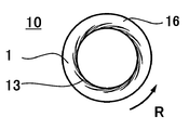
- FIG. 1 is a schematic cross-sectional view of a fluid processing apparatus according to an embodiment of the present invention. It is a principal part enlarged view of the processing surface of the fluid processing apparatus shown in FIG. 2 is a TEM photograph of iron oxide fine particles obtained in Example 1.
- FIG. 4 is a TEM photograph of iron oxide fine particles of Comparative Example 1.
- 2 is an ultraviolet-visible transmission spectrum of the iron oxide fine particle dispersion obtained in Example 1.
- 3 is a graph showing a molar extinction coefficient with respect to a measurement wavelength of the iron oxide fine particle dispersion obtained in Example 1.
- 4 is a TEM photograph of iron oxide fine particles obtained in Example 2.
- 2 is an ultraviolet-visible transmission spectrum of the iron oxide fine particle dispersion obtained in Example 2.
- FIG. 4 is a graph showing a molar extinction coefficient with respect to a measurement wavelength of the iron oxide fine particle dispersion obtained in Example 2.
- FIG. 6 is a dispersion diagram showing the relationship between the single crystal ratio and the haze value in Examples 1 to 8 and Comparative Examples 2 to 8.
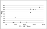
- FIG. 6 is a dispersion diagram showing the relationship between the average primary particle diameter and haze value according to Examples 1 to 8 and Comparative Examples 2 to 8.
- FIG. 6 is a dispersion diagram showing the relationship between secondary particle diameter (volume average particle diameter) and haze value according to Examples 1 to 8 and Comparative Examples 2 to 8.
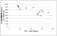
- FIG. 6 is a dispersion diagram showing the relationship between the single crystal ratio and the transmittance according to Examples 1 to 8 and Comparative Examples 2 to 8.
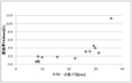
- FIG. 6 is a dispersion diagram showing the relationship between the average primary particle diameter and the transmittance according to Examples 1 to 8 and Comparative Examples 2 to 8.
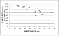
- FIG. 6 is a dispersion diagram showing the relationship between secondary particle diameter (volume average particle diameter) and transmittance according to Examples 1 to 8 and Comparative Examples 2 to 8.
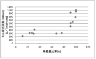
- FIG. 6 is a dispersion diagram showing the relationship between the ratio of single crystals according to Examples 1 to 8 and Comparative Examples 2 to 8 and the molar extinction coefficient with respect to light having a wavelength of 400 nm.
- FIG. 6 is a dispersion diagram showing the relationship between the average primary particle diameter and the molar extinction coefficient for light having a wavelength of 400 nm according to Examples 1 to 8 and Comparative Examples 2 to 8.
- FIG. 6 is a dispersion diagram showing the relationship between secondary particle diameter (volume average particle diameter) and molar extinction coefficient with respect to light having a wavelength of 400 nm according to Examples 1 to 8 and Comparative Examples 2 to 8.
- FIG. 7 is a dispersion diagram showing the relationship between the single crystal ratios of Examples 1 to 8 and Comparative Examples 2 to 8 and the molar extinction coefficient with respect to light having a wavelength of 220 nm.
- FIG. 6 is a dispersion diagram showing the relationship between the average primary particle diameter and the molar extinction coefficient for light having a wavelength of 220 nm according to Examples 1 to 8 and Comparative Examples 2 to 8.
- FIG. 6 is a dispersion diagram showing the relationship between secondary particle diameter (volume average particle diameter) and molar extinction coefficient for light having a wavelength of 220 nm according to Examples 1 to 8 and Comparative Examples 2 to 8.
- FIG. 6 is a dispersion diagram showing the relationship between the pH and the single crystal ratio after treatment in step (a) or step (a-2) according to Examples 1 to 8 and Comparative Examples 2 to 8.
- FIG. 7 is a dispersion diagram showing the relationship between the pH after treatment in step (a) or step (a-2) and average primary particle diameter according to Examples 1 to 8 and Comparative Examples 2 to 8.
- FIG. 6 is a dispersion diagram showing the relationship between the pH after treatment in step (a) or step (a-2) and secondary particle size (volume average particle size) according to Examples 1 to 8 and Comparative Examples 2 to 8.
- 4 is a TEM photograph of iron oxide fine particles obtained in Comparative Example 9.
- This invention is a manufacturing method of the ultraviolet protective composition which contains a process (a) and a process (b) at least.
- Step (a) is a step of precipitating iron oxide fine particles by mixing, using a microreactor, an iron oxide raw material fluid containing at least Fe 3+ ions and an iron oxide precipitation fluid containing at least a basic substance.
- the step (b) is a step of obtaining an iron oxide fine particle dispersion by dispersing the precipitated iron oxide fine particles in a dispersion medium.
- the iron oxide raw material fluid is obtained by dissolving or molecularly dispersing an iron oxide raw material in a solvent, and the iron oxide raw material is not particularly limited, and examples thereof include compounds such as iron simple substance and salts. Inorganic compounds of iron such as iron sulfate, iron nitrate, and iron chloride, and organic compounds of iron such as iron acetate and iron citrate.
- iron sulfate (II) FeSO 4
- iron nitrate (II) Fe (NO 3 ) 2
- Inorganic salts of ferrous iron (Fe (II)) such as iron chloride (II) (FeCl 2 ), iron acetate (II) (Fe (COOH) 2 ), ferrous citrate (II) (Fe (C 6 H 5 O 7 M 2 ): M is an organic salt of ferrous iron (Fe (II)) such as alkali metal or ammonium.
- Fe 3+ ion As substance which produces Fe 3+ ion is a trivalent iron ion in solution, iron sulphate (III) (Fe 2 (SO 4) 3) and iron nitrate (III) (Fe (NO 3 ) 3), Inorganic salts of ferric (Fe (III)) such as iron (III) chloride (FeCl 3 ), iron (III) acetate (Fe (COOH) 3 or Fe (OH) (CH 3 COO) 2 ), Examples thereof include organic salts of ferric iron (Fe (III)) such as ferric acid (III) (C 6 H 5 FeO 7 ). Substances that generate Fe 3+ ions in these solutions can also be carried out using hydrates or solvates thereof.
- the iron oxide in the present invention is preferably ⁇ -hematite (Fe 2 O 3 )
- the iron ion contained in the iron oxide raw material is preferably Fe 3+ . Therefore, as the iron oxide raw material, it is preferable to use a substance that generates Fe 3+ ions in a solution.
- the iron oxide raw material may be prepared using a means such as dissolving a substance that generates Fe 2+ ions in a solvent and changing the Fe 2+ ions to Fe 3+ ions with an oxidizing acid such as nitric acid.
- Basic substances used in the iron oxide precipitation fluid for mixing with the iron oxide raw material fluid to precipitate iron oxide include metal hydroxides such as sodium hydroxide and potassium hydroxide, sodium methoxide and sodium isopropoxide. And metal compounds such as ammonia, triethylamine, and amine compounds such as diethylaminoethanol and diethylamine.
- the iron oxide raw material fluid is preferably prepared by dissolving or molecularly dispersing an iron oxide raw material in a solvent
- the iron oxide precipitation fluid may be prepared by mixing, dissolving or molecularly dispersing a basic substance in a solvent.
- the solvent used for the iron oxide raw material fluid or the iron oxide precipitation fluid include water, an organic solvent, and a mixed solvent composed of a plurality of them.
- the water include tap water, ion-exchanged water, pure water, ultrapure water, and RO water.
- the organic solvent include alcohol compound solvents, amide compound solvents, ketone compound solvents, ether compound solvents, and aromatic compounds.
- Examples include solvents, carbon disulfide, aliphatic compound solvents, nitrile compound solvents, sulfoxide compound solvents, halogen compound solvents, ester compound solvents, ionic liquids, carboxylic acid compounds, and sulfonic acid compounds.
- solvents carbon disulfide, aliphatic compound solvents, nitrile compound solvents, sulfoxide compound solvents, halogen compound solvents, ester compound solvents, ionic liquids, carboxylic acid compounds, and sulfonic acid compounds.
- Each of the above solvents may be used alone or in combination of two or more.
- the iron oxide raw material fluid or the iron oxide precipitation fluid is prepared by rotating a stirrer having various shapes such as a rod shape, a plate shape, or a propeller shape in a tank, or rotating relative to the stirrer. It is desirable to use a material that achieves homogeneous mixing by applying a shearing force to the fluid, such as a material having a screen.
- a stirrer disclosed in Japanese Patent No. 5147091 can be applied.
- the rotary disperser may be a batch type or a continuous type.
- the supply and discharge of fluid to the stirring tank may be performed continuously, or may be performed using a continuous mixer without using the stirring tank,
- the stirring energy can be appropriately controlled using a known stirrer or stirring means.
- the agitation energy is described in detail in Japanese Patent Application Laid-Open No. 04-114725 by the applicant of the present application.
- the stirring method in the present invention is not particularly limited, but can be carried out by using various shearing type, friction type, high pressure jet type, ultrasonic type stirring machines, dissolving machines, emulsifiers, dispersing machines, hosnizers and the like. .
- Examples include Ultra Tarrax (manufactured by IKA), Polytron (manufactured by Kinematica), TK Homomixer (manufactured by Primex), Ebara Milder (manufactured by Ebara Seisakusho), TK Homomic Line Flow (manufactured by Primics), Colloid Mill (manufactured by Shinko Pan) Tech), Thrasher (Nihon Coke Kogyo), Trigonal wet pulverizer (Mitsui Miike Chemical), Cavitron (Eurotech), Fine Flow Mill (Pacific Kiko), etc. ⁇ Batch-type or continuous-use emulsifiers such as Technic), Claremix dissolver (MTechnic), and Fillmix (Primics) can be mentioned. Further, the stirring treatment is desirably performed using a stirrer equipped with a rotating stirring blade, particularly the above-mentioned Claremix (made by M Technique) or Claremix dissolver (made by M Technique).
- Step (a) it is preferable to mix the iron oxide raw material fluid and the iron oxide precipitation fluid using a microreactor, and among them, the same devices as those described in Patent Document 4 and Patent Document 5 shown in FIG. It is preferable to use one.
- the microreactor will be described in detail.
- R indicates the direction of rotation.
- the microreactor (hereinafter also referred to as a fluid processing apparatus) in the present embodiment includes first and second processing units 10 and 20 that face each other, and the first processing unit 10 rotates.
- the opposing surfaces of both processing parts 10 and 20 are processing surfaces.
- the first processing unit 10 includes a first processing surface 1
- the second processing unit 20 includes a second processing surface 2.
- Both processing surfaces 1 and 2 are respectively connected to the flow paths d1 and d2 of the fluid to be processed, and constitute a part of the flow path of the fluid to be processed.
- the distance between the processing surfaces 1 and 2 is usually adjusted to 1 mm or less, for example, a minute distance of about 0.1 ⁇ m to 50 ⁇ m. As a result, the fluid to be processed passing between the processing surfaces 1 and 2 becomes a forced thin film fluid forced by the processing surfaces 1 and 2.
- this fluid processing apparatus performs the fluid processing which makes the 1st, 2nd to-be-processed reaction react between the processing surfaces 1 and 2, and precipitates iron oxide microparticles
- the apparatus includes a first holder 11 that holds the first processing portion 10, a second holder 21 that holds the second processing portion 20, and a contact pressure application mechanism 43. , A rotation drive mechanism (not shown), a first introduction part d1, a second introduction part d2, and fluid pressure application mechanisms p1 and p2.
- a compressor or other pump can be employed for the fluid pressure imparting mechanisms p1 and p2.
- the first processing unit 10 and the second processing unit 20 are ring-shaped disks.
- the materials of the first and second processing parts 10 and 20 are metal, carbon, ceramic, sintered metal, wear-resistant steel, sapphire, other metals subjected to hardening treatment, hard material lining, Those with coating, plating, etc. can be used.
- the processing portions 10 and 20 have the first and second processing surfaces 1 and 2 facing each other mirror-polished, and the arithmetic average roughness is 0.01 to 1.0 ⁇ m. It is.
- the second holder 21 is fixed to the apparatus, and the first holder 11 attached to the rotary shaft 50 of the rotation drive mechanism fixed to the apparatus is rotated and supported by the first holder 11.
- the first processing unit 10 thus rotated rotates with respect to the second processing unit 20.
- the second processing unit 20 may be rotated, or both may be rotated.
- the rotation speed can be set to 350 to 5000 rpm, for example.
- the second processing unit 20 approaches and separates from the first processing unit 10 in the direction of the rotation shaft 50, and the storage unit 41 provided in the second holder 21 has the first 2 A portion of the processing portion 20 opposite to the processing surface 2 side is accommodated so that it can appear and disappear.
- the first processing unit 10 may approach or separate from the second processing unit 20, and both processing units 10 and 20 may approach or separate from each other. It may be.
- the accommodating portion 41 is a recess that accommodates a portion of the second processing portion 20 on the side opposite to the processing surface 2 side, and is a groove formed in an annular shape.
- the accommodating portion 41 accommodates the second processing portion 20 with a sufficient clearance that allows the portion of the second processing portion 20 on the side opposite to the processing surface 2 side to appear.
- the contact surface pressure applying mechanism is a force that pushes the first processing surface 1 of the first processing portion 10 and the second processing surface 2 of the second processing portion 20 in the approaching direction (hereinafter referred to as contact surface pressure). It is a mechanism for generating. The balance between the contact surface pressure and the force that separates the processing surfaces 1 and 2 due to the fluid pressure keeps the distance between the processing surfaces 1 and 2 at a predetermined minute distance while maintaining the unit of nm to ⁇ m. A thin film fluid having a minute film thickness is generated.
- the contact surface pressure applying mechanism is configured such that the spring 43 provided in the second holder 21 biases the second processing member 20 toward the first processing member 10, thereby Is granted.
- the first fluid to be treated pressurized by the fluid pressure imparting mechanism p1 is introduced from the first introduction part d1 into the space inside both the processing parts 10 and 20.
- the second fluid to be processed pressurized by the fluid pressure imparting mechanism p2 is formed on the second processing surface from the second introduction part d2 through the passage provided in the second processing part 20. It is introduced into the space inside both the processing parts 10 and 20 from the opened opening d20.
- the first fluid to be treated and the second fluid to be treated merge and mix.
- the mixed fluid to be processed becomes a thin film fluid forced by both processing surfaces 1 and 2 holding the above-mentioned minute gaps, and tries to move to the outside of both annular processing surfaces 1 and 2. Since the first processing unit 10 is rotating, the mixed fluid to be processed does not move linearly from the inside to the outside of the two processing surfaces 1 and 2 in the annular shape, but in the annular radial direction. A combined vector of the movement vector and the movement vector in the circumferential direction acts on the fluid to be processed and moves in a substantially spiral shape from the inside to the outside.
- the first processing surface 1 of the first processing portion 10 has a groove-like recess extending from the center side of the first processing portion 10 toward the outside, that is, in the radial direction. 13 may be formed.
- the planar shape of the recess 13 is curved or spirally extending on the first processing surface 1, or is not illustrated, but extends straight outward, bent or curved in an L shape, It may be continuous, intermittent, or branched.
- the concave portion 13 can be implemented as one formed on the second processing surface 2, and can also be implemented as one formed on both the first and second processing surfaces 1, 2.
- the base end of the recess 13 reaches the inner periphery of the first processing unit 10.
- the front end of the concave portion 13 extends toward the outer peripheral surface of the first processing surface 1, and the depth gradually decreases from the base end toward the front end.
- a flat surface 16 without the recess 13 is provided between the tip of the recess 13 and the outer peripheral surface of the first processing surface 1.
- the opening d20 described above is preferably provided at a position facing the flat surface of the first processing surface 1.
- the introduction direction from the opening d20 of the second processing surface 2 may be inclined at a predetermined elevation angle with respect to the second processing surface 2, or from the opening d20 of the second processing surface 2.
- the introduction direction of the second fluid has directionality in the plane along the second processing surface 2, and the introduction direction of the second fluid is an outward direction away from the center in the radial component of the processing surface.
- the component in the direction of rotation of the fluid between the rotating processing surfaces may be the forward direction.
- the flow of the first fluid to be processed in the opening d20 is laminar, and the second introduction portion d2 has directionality, thereby generating turbulence with respect to the flow of the first fluid to be processed.
- the second fluid to be processed can be introduced between the processing surfaces 1 and 2 while suppressing the above.
- the fluid discharged to the outside of the processing parts 10 and 20 is collected in the beaker b as a discharge liquid via the vessel v.
- the discharge liquid contains iron oxide fine particles.
- the number of the fluids to be processed and the number of the flow paths are two in the example of FIG. 1, they may be three or more.
- the shape, size, and number of the opening for introduction provided in each processing part are not particularly limited and can be appropriately changed.
- the shape of the opening d20 may be a concentric annular shape surrounding the central opening of the processing surface 2 which is a ring-shaped disk, and the annular opening is It may be continuous or discontinuous.
- an opening for introduction may be provided immediately before or between the first and second processing surfaces 1 and 2 or further upstream.
- an iron oxide raw material fluid is introduced as a first fluid to be treated from the first introduction part d1, and an iron oxide precipitation fluid is introduced from the second introduction part.
- the at least two kinds of fluids can be mixed between the processing surfaces 1 and 2 to precipitate iron oxide fine particles.
- the liquid feeding temperature of the said iron oxide raw material fluid shall be more than a boiling point.
- the above processing can be performed between the processing surfaces 1 and 2, and the second treated fluid is introduced from the first introduction part d1 and the first treated fluid is introduced from the second introduction part d2. It may be introduced.
- the expressions “first” and “second” in each fluid have only the meaning of identification that they are the nth of a plurality of fluids, and there are also three or more fluids as described above. Yes.
- the primary particle diameter of the precipitated iron oxide fine particles is preferably 25 nm or less.
- the haze value is 2.0% or less, and the transmittance of light having a wavelength of 200 to 420 nm is 2.0% or less. It is possible to produce an ultraviolet protection composition that is
- Step (a-2) In the present invention, after the fluid to be treated is discharged from between the processing surfaces and before the step (b), the step of further stirring the discharged fluid to be treated (a-2) ) Is preferably included.
- various dispersants and surfactants described later may be added to the discharged fluid to be treated.
- the same one used for the preparation of the iron oxide raw material fluid or the iron oxide precipitation fluid described above is used, but various shapes of agitation bars such as rods, plates, and propellers are used in the tank. It is desirable to use a stirrer that achieves homogeneous mixing by applying a shearing force to the fluid, such as those that are rotated at the same time or those that are provided with a screen that rotates relative to the stirrer.
- a stirrer disclosed in Japanese Patent No. 5147091 can be applied.
- the rotary disperser may be a batch type or a continuous type.
- the supply and discharge of fluid to the stirring tank may be performed continuously, or may be performed using a continuous mixer without using the stirring tank,
- the stirring energy can be appropriately controlled using a known stirrer or stirring means.
- the agitation energy is described in detail in Japanese Patent Application Laid-Open No. 04-114725 by the applicant of the present application.
- the stirring method in the present invention is not particularly limited, but can be carried out by using various shearing type, friction type, high pressure jet type, ultrasonic type stirring machines, dissolving machines, emulsifiers, dispersing machines, hosnizers and the like. .
- Examples include Ultra Tarrax (manufactured by IKA), Polytron (manufactured by Kinematica), TK Homomixer (manufactured by Primex), Ebara Milder (manufactured by Ebara Seisakusho), TK Homomic Line Flow (manufactured by Primics), Colloid Mill (manufactured by Shinko Pan) Tech), Thrasher (Nihon Coke Kogyo), Trigonal wet pulverizer (Mitsui Miike Chemical), Cavitron (Eurotech), Fine Flow Mill (Pacific Kiko), etc. ⁇ Batch-type or continuous-use emulsifiers such as Technic), Claremix dissolver (MTechnic), and Fillmix (Primics) can be mentioned. Further, the stirring treatment is desirably performed using a stirrer equipped with a rotating stirring blade, particularly the above-mentioned Claremix (made by M Technique) or Claremix dissolver (made by M Technique).
- the transmittance at a wavelength of 420 nm of the iron oxide fine particle dispersion was lower than when the stirring treatment was not performed. Further, when a stirring process is performed, when a dispersant described later is added to the discharged fluid to be treated, the transmittance at a wavelength of 420 nm of the iron oxide fine particle dispersion is lower than when the stirring process is not performed. It was. As described above, by performing the stirring treatment, the iron oxide fine particle dispersion can absorb or shield more ultraviolet rays and improve the ultraviolet protection ability, compared with the case where the stirring treatment is not performed. It has been found by the present inventor that it is possible to control both the primary particle size and the crystallinity by appropriately performing this stirring treatment.
- the primary particle size and crystallinity have been found by the present inventor to affect dispersibility (secondary particle size), haze value, transmittance, and molar extinction coefficient.
- the manufacturing method has been completed. For example, it has been found that the crystallinity can be improved even if the primary particle diameter is substantially the same depending on the presence or absence of the stirring treatment, and as a result, the absorption region extends from the ultraviolet region to the visible region side.
- Step (b) The present invention includes the step (b) of obtaining the iron oxide fine particle dispersion by dispersing the precipitated iron oxide fine particles in a solvent that can serve as a dispersion medium.
- a solvent which can become a dispersion medium
- the mixed solvent which consists of water, an organic solvent, or those plurality is mentioned.
- the water include tap water, ion-exchanged water, pure water, ultrapure water, and RO water.
- the organic solvent include alcohol compound solvents, amide compound solvents, ketone compound solvents, ether compound solvents, and aromatic compounds.
- Disperse solvent carbon disulfide, aliphatic compound solvent, nitrile compound solvent, sulfoxide compound solvent, halogen compound solvent, ester compound solvent, ionic liquid, carboxylic acid compound, sulfonic acid compound, or oil such as silicone or castor oil Can be used.
- solvents may be used alone or in combination of two or more.
- the disperser used for dispersion is the same as that used for the preparation of the iron oxide raw material fluid or the iron oxide precipitation fluid described above, but a stirrer of various shapes such as a rod shape, a plate shape, and a propeller shape is used in the tank. It is desirable to use a material that achieves homogeneous mixing by applying a shearing force to the fluid, such as a material that rotates with a stirrer or a screen that rotates relative to the stirrer. As a preferred example of the rotary disperser, a stirrer disclosed in Japanese Patent No. 5147091 can be applied.
- the rotary disperser may be a batch type or a continuous type.
- the supply and discharge of fluid to the stirring tank may be performed continuously, or may be performed using a continuous mixer without using the stirring tank,
- the stirring energy can be appropriately controlled using a known stirrer or stirring means.
- the agitation energy is described in detail in Japanese Patent Application Laid-Open No. 04-114725 by the applicant of the present application.
- the stirring method in the present invention is not particularly limited, but can be carried out by using various shearing type, friction type, high pressure jet type, ultrasonic type stirring machines, dissolving machines, emulsifiers, dispersing machines, hosnizers and the like. .
- Examples include Ultra Tarrax (manufactured by IKA), Polytron (manufactured by Kinematica), TK Homomixer (manufactured by Primex), Ebara Milder (manufactured by Ebara Seisakusho), TK Homomic Line Flow (manufactured by Primics), Colloid Mill (manufactured by Shinko Pan) Tech), Thrasher (Nihon Coke Kogyo), Trigonal wet pulverizer (Mitsui Miike Chemical), Cavitron (Eurotech), Fine Flow Mill (Pacific Kiko), etc. ⁇ Batch-type or continuous-use emulsifiers such as Technic), Claremix dissolver (MTechnic), and Fillmix (Primics) can be mentioned. Further, the stirring treatment is desirably performed using a stirrer equipped with a rotating stirring blade, particularly the above-mentioned Claremix (made by M Technique) or Claremix dissolver (made by M Technique).
- various dispersants and surfactants can be used according to the purpose and necessity.
- a surfactant and a dispersing agent various commercially available products generally used, products, or newly synthesized products can be used. Examples include anionic surfactants, cationic surfactants, nonionic surfactants, dispersants such as various polymers, and the like. These may be used alone or in combination of two or more.
- Said surfactant and dispersing agent may be contained in either or both of the iron oxide raw material liquid and the iron oxide precipitation solvent.
- said surfactant and dispersing agent may be contained in the 3rd fluid mentioned later which is different from an iron oxide raw material liquid and an iron oxide precipitation solvent. Further, it may be contained in the dispersion medium.
- the iron oxide fine particle dispersion is not limited to be dispersed in a liquid dispersion medium. Even if it is dispersed in a solid such as glass or resin.
- the step (a) and the step (b) are included, so that the iron oxide fine particle dispersion has a haze value of 2.0% or less and a light transmittance of 200 to 420 nm. It is possible to obtain an ultraviolet protective composition that is 0.0% or less.
- the inventor of the present invention provides a light beam having a wavelength of 200 to 420 nm of iron oxide fine particles in an iron oxide fine particle dispersion produced by a method comprising the steps (a) and (b), comprising producing using the microreactor. It is considered that the present invention has been completed when the molar extinction coefficient is higher than that of the conventional one.
- the iron oxide fine particles have a molar extinction coefficient with respect to light having a wavelength of 400 nm of 500 L / (mol ⁇ cm) or more and a molar extinction coefficient with respect to light having a wavelength of 220 nm of 3000 L / (mol ⁇ cm) or more.
- the molar extinction coefficient can be calculated by the following formula from the absorbance and the molar concentration in the UV-visible absorption spectrum measurement.
- ⁇ A / (c ⁇ l)
- ⁇ is a constant specific to the substance and is called a molar extinction coefficient, and is a reciprocal of the ratio of light intensity when light passes through a 1 mol / L solution having a thickness of 1 cm.
- A is the absorbance in the UV-visible absorption spectrum measurement
- c is the molar concentration (mol / L) of the sample.
- l is the length (light path length) through which light passes, and is usually the thickness of the cell when measuring the UV-visible absorption spectrum.
- the haze value is a numerical value indicating transparency. For example, when an ultraviolet protective composition having a haze value exceeding 2% is applied on a paint for buildings or automobiles, the color of the paint as a base is impaired. This will inhibit the intended coloring. Also, when applied to the human skin or the like, it is not preferable to use a haze value exceeding 2% and having a low transmittance because the texture and appearance are impaired.
- the molar extinction coefficient is smaller than that of the conventional one. Therefore, since it is not necessary to use a large amount of iron oxide, it is also an effect that can be exhibited when actually using the ultraviolet protection composition.
- the molar extinction coefficient is the ability to absorb ultraviolet light with respect to iron oxide per unit mole, the molar extinction coefficient with respect to light having a wavelength of 400 nm of the iron oxide fine particle dispersion is 500 L / (mol ⁇ cm) or more, and light having a wavelength of 220 nm.
- the molar extinction coefficient with respect to is 3000 L / (mol ⁇ cm) or more, the performance as an ultraviolet protective composition is appropriately exhibited, and a large amount is required when used in a method such as coating. It is possible to suppress the possibility of impairing haze value and transmittance.
- the iron oxide fine particles in the iron oxide fine particle dispersion produced in the present invention have not only increased surface area but also high crystallinity due to the primary particle size and the secondary particle size being smaller than the conventional ones. This is considered to be a factor that increases the molar extinction coefficient.
- the shape of the particles is less affected than the above factors and may be of various shapes, but is preferably substantially spherical.
- Performing the step of precipitating iron fine particles is effective in terms of obtaining substantially spherical particles having a primary particle size and a secondary particle size smaller than those of conventional ones and high crystallinity.
- the particle size and monodispersity of the magnetic fine particles obtained, and the control of crystallinity and crystallinity are controlled by the rotational speed of the processing surface, the distance between the processing surfaces, and the thin film fluid.
- the present inventor conducted research based on the techniques disclosed in Patent Documents 4 and 5, but in the case of iron oxide, even if the temperature of the thin film fluid is simply controlled under relatively small pressure conditions, Iron oxide particles could not be obtained. After that, as a result of extensive research by the inventors after trial and error, the crystallinity of the iron oxide particles is drastically improved by setting the temperature of the iron oxide raw material liquid to a predetermined temperature or higher under relatively large pressure conditions. I found that it was possible. Specifically, the iron oxide raw material to be introduced between the processing surfaces is set so that the introduction pressure between the processing surfaces of the processing fluids of both the iron oxide raw material fluid and the iron oxide deposition fluid exceeds the standard atmospheric pressure.
- the crystallinity of the iron oxide particles can be drastically improved by setting the temperature of the fluid higher than the normal boiling point of the fluid and lower than the boiling point under the introduction pressure. It was issued. According to this method, 90% or more of the obtained iron oxide particles can be obtained as a single crystal, the haze value is 2.0% or less, and the transmittance of light having a wavelength of 200 to 420 nm. Can be produced at 2.0% or less.
- the standard boiling point of this iron oxide raw material fluid varies depending on the type and blending ratio of the iron oxide raw material fluid. In practice, the standard boiling point of the iron oxide raw material fluid is calculated and supplied to a temperature higher than the calculated value. What is necessary is just to set the temperature of the iron oxide raw material fluid to perform.
- the pH of the fluid mixed between the processing surfaces in the step (a) or the pH of the fluid obtained in the step (a-2) is preferably 6 or more and 14 or less, and 8 or more and 12 More preferably, it is as follows.
- the pH of the fluid is 8 or more, 90% or more of the iron oxide particles may be single crystallized.
- mixing the iron oxide raw material fluid and the iron oxide deposition fluid may generate reaction heat such as heat of neutralization, and the heat energy of the fluid to be treated with heat generated by reaction heat such as neutralization heat.
- reaction heat such as heat of neutralization
- the oxide fine particles are single crystals
- TEM transmission electron microscope
- SEM scanning electron microscope
- XRD measurement X-ray diffraction measurement
- the criterion for determining whether or not each particle is a single crystal is that a lattice pattern (atomic arrangement in the crystal) is observed in one direction is recognized as a single crystal, and the lattice pattern is Those that are disturbed or have grain boundaries are recognized as not being single crystals.
- an iron oxide raw material fluid is used as the A liquid
- an iron oxide precipitation fluid is used as the B liquid
- the A liquid and the B liquid are mixed using a microreactor to precipitate the iron oxide fine particles. Disperse in a dispersion medium.
- the product name: ULREA manufactured by M Technique
- the liquid A corresponds to the first fluid to be treated introduced from the first introduction part d1 of the microreactor shown in FIG. 1
- the liquid B corresponds to the second fluid to be treated similarly introduced from the second introduction part d2.
- the replacement of the first introduction part d1 and the second introduction part d2 is arbitrary.
- the obtained iron oxide fine particles were analyzed under the following conditions. *
- XRD measurement a powder X-ray diffraction measurement device (product name: X′Pert PRO MPD, manufactured by PANalytical) was used.
- the measurement conditions are: measurement range: 10 to 100 °, Cu counter cathode, tube voltage 45 kV, tube current 40 mA, scanning speed 16 ° / min.
- the crystallite diameter was calculated using a peak near 44 ° and using a silicon polycrystalline plate as a reference.
- the primary particle diameter D1 of the iron oxide fine particle of an Example and a comparative example is an average value (average primary particle diameter) as a result of measuring a particle diameter about 100 particles by TEM observation.
- a particle size distribution measuring device (UPA-UT151, manufactured by Nikkiso) was used. Measurement conditions were such that the measurement solvent was propylene glycol and the solvent refractive index was 1.43. The refractive index of the particles was 2.94, the specific gravity was 5.24 g / cm 3, and the volume average particle diameter in the measurement results was D2.
- a visible ultraviolet absorption spectrophotometer (product name: UV-2450, manufactured by Shimadzu Corporation) was used. The measurement range was 200 to 800 nm, the sampling rate was 0.2 nm, and the measurement speed was low.
- the transmission spectrum was measured with an iron oxide concentration of 0.005 wt%.
- the iron oxide concentration was measured at 0.005 wt% or less, and after measuring the absorption spectrum, the molar extinction coefficient was calculated from the absorbance obtained from the measurement results and the iron oxide concentration of the measurement solution, and the horizontal axis It was set as the graph which described the molar absorption coefficient on the measurement wavelength and the vertical axis
- a liquid cell having a thickness of 1 cm was used.
- a haze meter (model HZ-V3, manufactured by Suga Test Instruments) was used for haze value measurement.
- the D65 light was used as a light source by a double beam system corresponding to JIS K 7136 and JIS K 7361 as optical conditions.
- the measurement was performed on the same liquid as that used in the UV-visible transmission spectrum measurement in a liquid cell having a thickness of 1 mm.
- solution A iron (III) nitrate nonahydrate / pure water was mixed at a weight ratio of 2.0 / 98.0, and Claremix (product name: CLM-2.2S, manufactured by M Technique) was used. It was prepared by stirring at a rotation speed of 20000 rpm, a processing temperature of 24 to 60 ° C., and a processing time of 60 min, mixing and dissolving.
- solution B sodium hydroxide / pure water is mixed at a weight ratio of 9.0 / 91.0, and the mixture is mixed and dissolved by stirring at a rotation speed of 8000 rpm, a processing temperature of 50 ° C., and a processing time of 30 minutes using CLEARMIX. Prepared.
- Example 1 Using the microreactor shown in FIG. 1, the liquid A and liquid B having the formulation shown in Table 1 are introduced between the processing surfaces 1 and 2 under the processing conditions shown in Table 1, and between the processing surfaces 1 and 2 The mixture was mixed in the formed thin film fluid to precipitate iron oxide fine particles.
- a slurry liquid containing iron oxide fine particles deposited between the processing surfaces 1 and 2 (hereinafter also referred to as a discharge liquid) was discharged from between the processing surfaces 1 and 2 and collected in the beaker b through the vessel v.
- the rotation speed of the processing unit 10 is 1700 rpm.
- Fe (NO 3) 3 ⁇ 9H 2 O is iron (III) nitrate nonahydrate
- NaOH is sodium hydroxide
- SDS is sodium dodecyl sulfate
- HEC is hydroxy ethyl cellulose.
- Example 1 and 4-8 the discharged liquid collected in the beaker b was allowed to stand until the temperature became 60 ° C. or lower, and iron oxide fine particles were allowed to settle.
- Example 2 and 3 the discharged liquid collected in the beaker b is stirred under the conditions shown in Table 1, and the liquid obtained after the stirring process is allowed to stand until it becomes 60 ° C. or lower. The iron oxide fine particles were allowed to settle.
- the stirring process in Example 2, the discharged liquid collected in the beaker b was stirred at 20000 rpm using Claremix for 1 hour at 100 ° C. without cooling.
- the surfactant, SDS is added at a rate of 100 wt% with respect to the iron oxide without cooling, and is 20,000 rpm using Claremix at 100 ° C. for 1 hour. Was stirred at.
- the supernatant liquid in the beaker b is removed, pure water having a weight of 20 to 1500 times the weight of the precipitated iron oxide fine particles is added, and using a CLEARMIX, the rotation speed is 6000 rpm, the treatment temperature is 25 ° C., and the treatment time is 5 minutes.
- the iron oxide fine particles were washed. After performing the above washing operation three times, the iron oxide fine particles were settled again, and the supernatant was removed to obtain a wet cake containing iron oxide fine particles.
- the obtained dispersion was diluted with isopropyl alcohol, subjected to a dispersion treatment with an ultrasonic cleaner, and then dropped onto a collodion film and dried to obtain a TEM observation sample.
- the wet wet cake of iron oxide fine particles obtained after washing was dried at ⁇ 0.10 MpaG at 20 ° C. for 15 hours or more to obtain iron oxide fine particle powder.
- Table 2 Of the results shown in Table 2, regarding the transmittance (wavelength 650 to 800 nm), the result of measuring the ultraviolet-visible transmission spectrum of the iron oxide fine particle dispersion shows that the transmittance at the wavelength 650 to 800 nm is 80% or more.
- post-treatment pH indicates the pH of the liquid obtained after the stirring treatment in the examples and comparative examples in which the stirring treatment was performed, and the examples in which the stirring treatment was not performed.
- recovered by the beaker b is shown.
- all of the samples had “the haze value of the iron oxide fine particle dispersion is 2.0% or less and the iron oxide fine particle dispersion described above. Therefore, the transmittance of light having a wavelength of 200 to 420 nm is not more than 2.0%. Therefore, it is considered unsuitable as an ultraviolet protective composition.
- Comparative Example 1 iron oxide (III) ( ⁇ -Fe 2 O 3) manufactured by Wako Pure Chemical Industries, Ltd. was dispersed in propylene glycol in the same manner as in Example 1, and the haze value, particle size distribution, and UV-visible transmission absorption spectrum were measured.
- a dispersion having an iron oxide concentration of 0.005 wt% is used.
- a dispersion having an iron oxide concentration of 0.005 wt% or less is used. Measured. Further, the obtained dispersion was diluted with isopropyl alcohol, subjected to a dispersion treatment with an ultrasonic cleaner, and then dropped onto a collodion film and dried to obtain a TEM observation sample.
- Example 2-10 Iron oxide fine particles were precipitated in the same manner as in Example 1-8 except that the formulation and processing conditions of the iron oxide raw material fluid and the iron oxide precipitation fluid were changed to those shown in Table 1.
- a slurry liquid containing iron oxide fine particles deposited between the processing surfaces 1 and 2 (hereinafter also referred to as a discharge liquid) was discharged from between the processing surfaces 1 and 2 and collected in the beaker b through the vessel v.
- Comparative Examples 4 and 7-10 the discharged liquid collected in the beaker b was allowed to stand until it became 60 ° C. or less, and iron oxide fine particles were allowed to settle. Further, in Comparative Examples 2, 3, 5, and 6, the discharged liquid collected in the beaker b is stirred under the conditions shown in Table 1, and the liquid obtained after the stirring is 60 ° C. or lower. Until the iron oxide fine particles were allowed to settle. As a stirring process, in Comparative Example 2, the discharge liquid collected in the beaker b was not cooled, and hydroxyethyl cellulose (hereinafter referred to as HEC), which is a polymer activator, was 100 wt% with respect to iron oxide.
- HEC hydroxyethyl cellulose
- Comparative Example 3 the discharged liquid collected in the beaker b was not cooled and was a basic solvent hydroxylated. Sodium (hereinafter also referred to as NaOH) was added at a rate of 1.2 wt% with respect to iron oxide, and stirred at 100 ° C. for 1 hour at Claremix at 20000 rpm.
- Comparative Example 5 the discharged liquid collected in the beaker b was stirred at 100 ° C. for 1 hour at Clairemix 20000 rpm without cooling.
- Comparative Example 6 the discharged liquid was added to the beaker b. About the collect
- FIG. 25 shows a TEM photograph of the iron oxide fine particles obtained in Comparative Example 9.
- the substantially spherical shape means a substantially spherical shape. Specifically, when the particle shape is defined by a major axis and a minor axis, the ratio of the minor axis to the major axis is 0.5 to 1. Means in the range of .0.
- FIG. 4 shows a TEM photograph of the iron oxide fine particles obtained in Comparative Example 1.
- the average primary particle size was 119.6 nm.
- the volume average particle size was 125.4 nm, and the haze value was 21.9%.
- FIG. 5 shows the UV-visible transmission spectrum measurement results of the iron oxide fine particle dispersion obtained in Example 1
- FIG. 6 shows the molar extinction coefficient graph
- the iron oxide fine particle dispersion obtained in Example 1 did not substantially transmit ultraviolet light having a wavelength of 200 to 400 nm, and the transmittance at a wavelength of 420 nm was 1.94%. . Furthermore, it was found that the transmittance at a wavelength of 650 to 800 nm exceeded 80%.
- the transmittance of the iron oxide fine particle dispersion of Comparative Example 1 was approximately 20 to 30% in the entire measurement range, and no clear difference was observed between the absorption region and the transmission region.
- the molar extinction coefficient of the iron oxide fine particles obtained in Example 1 is 931 L / (mol ⁇ cm) for a light beam having a wavelength of 400 nm and 3575 L for light having a wavelength of 220 nm. / (Mol ⁇ cm).
- Example 2 a TEM photograph of the iron oxide fine particles obtained in Example 2 is shown in FIG.
- the average primary particle size was 8.50 nm.
- the volume average particle size was 27.6 nm and the haze value was 0.00%.
- FIG. 8 shows the results of ultraviolet-visible transmission spectrum measurement of the iron oxide fine particle dispersion obtained in Example 2
- FIG. 9 shows a graph of molar extinction coefficient.
- the iron oxide fine particle dispersion obtained in Example 2 did not substantially transmit ultraviolet light having a wavelength of 200 to 400 nm, and the transmittance at a wavelength of 420 nm was 0.77%. .
- the transmittance at a wavelength of 650 to 800 nm exceeded 80%. That is, it was found that light with a wavelength of 200 to 420 nm was absorbed and other light, particularly light with a wavelength of 650 to 800 nm, was transmitted over the entire measurement area.
- the molar extinction coefficient of the iron oxide fine particles obtained in Example 2 is 793 L / (mol ⁇ cm) for a light beam having a wavelength of 400 nm and 3481 L for light having a wavelength of 220 nm. / (Mol ⁇ cm).
- a peak of ⁇ -Fe 2 O 3 (hematite) was clearly detected.
- Example 3 From the TEM observation results of Example 3, the average primary particle size was 9.90 nm. As a result of measuring the particle size distribution of the iron oxide fine particle dispersion obtained in Example 3, the volume average particle size was 34.6 nm and the haze value was 1.12%. Further, from the results of ultraviolet visible transmission spectrum measurement, the iron oxide fine particle dispersion obtained in Example 3 does not substantially transmit ultraviolet light having a wavelength of 200 to 400 nm, and the transmittance at a wavelength of 420 nm is 1.79%. there were. Furthermore, it was found that the transmittance at a wavelength of 650 to 800 nm exceeded 80%.
- the average primary particle size was 12.30 nm.
- the volume average particle size was 59.1 nm and the haze value was 2.96%.
- the iron oxide fine particle dispersion obtained in Comparative Example 2 had a transmittance of 3.99% at a wavelength of 420 nm.
- the molar extinction coefficient of the iron oxide fine particles obtained in Comparative Example 2 was 314 L / (mol ⁇ cm) for light having a wavelength of 400 nm and 2841 L / (mol ⁇ cm) for light having a wavelength of 220 nm. .
- XRD measurement it was confirmed that the peak of ⁇ -Fe 2 O 3 (hematite) was small and broader than in Examples 1, 2, and 3 .
- the average primary particle diameter of the iron oxide fine particles obtained in Comparative Example 3 was 35.90 nm.
- the volume average particle size was 84.1 nm, and the haze value was 3.56%.
- the iron oxide fine particle dispersion obtained in Comparative Example 3 had a transmittance of 11.25% at a wavelength of 420 nm.
- the molar extinction coefficient of the iron oxide fine particles obtained in Comparative Example 3 was 296 L / (mol ⁇ cm) for light having a wavelength of 400 nm and 2514 L / (mol ⁇ cm) for light having a wavelength of 220 nm. .
- XRD measurement it was confirmed that the peak of ⁇ -Fe 2 O 3 (hematite) was small and broader than in Examples 1, 2, and 3 .
- the haze value is a summary of the above-described invention in relation to the single crystal ratio, the average primary particle diameter, and the secondary particle diameter (volume average particle diameter). And it is supported that the relationship shown in the embodiment for carrying out the invention is shown.
- the transmittance is related to the single crystal ratio, the average primary particle diameter, and the secondary particle diameter (volume average particle diameter). And it is supported that the relationship shown in the embodiment for carrying out the invention is shown. As shown in the above tables and FIGS.
- the molar extinction coefficient with respect to light having a wavelength of 400 nm is related to the single crystal ratio, the average primary particle size, and the secondary particle size (volume average particle size). It is confirmed that the above-described outline and the relationship shown in the mode for carrying out the invention are shown. As shown in each of the above tables and FIGS. 19 to 21, the molar extinction coefficient for light having a wavelength of 220 nm is related to the single crystal ratio, the average primary particle diameter, and the secondary particle diameter (volume average particle diameter). It is confirmed that the above-described outline and the relationship shown in the mode for carrying out the invention are shown. As shown in the above tables and FIGS.
- the pH after the treatment in the step (a) or the step (a-2) is the single crystal ratio, the average primary particle size and the secondary particle size (volume). In relation to the average particle diameter), it is supported that the relation shown in the outline of the invention and the embodiment for carrying out the invention is shown.
- the iron oxide fine particle dispersion obtained in the above examples was found to be an ultraviolet protective composition having high transparency and high ability to protect light in the ultraviolet region having a wavelength of 200 to 420 nm.
Landscapes
- Chemical & Material Sciences (AREA)
- Health & Medical Sciences (AREA)
- Life Sciences & Earth Sciences (AREA)
- Organic Chemistry (AREA)
- Public Health (AREA)
- Animal Behavior & Ethology (AREA)
- General Health & Medical Sciences (AREA)
- Veterinary Medicine (AREA)
- Engineering & Computer Science (AREA)
- Materials Engineering (AREA)
- Inorganic Chemistry (AREA)
- Birds (AREA)
- Epidemiology (AREA)
- Dermatology (AREA)
- Crystallography & Structural Chemistry (AREA)
- Metallurgy (AREA)
- Physics & Mathematics (AREA)
- Wood Science & Technology (AREA)
- Dispersion Chemistry (AREA)
- General Physics & Mathematics (AREA)
- Nanotechnology (AREA)
- Optics & Photonics (AREA)
- Toxicology (AREA)
- Chemical Kinetics & Catalysis (AREA)
- General Chemical & Material Sciences (AREA)
- Compounds Of Iron (AREA)
- Cosmetics (AREA)
- Inorganic Compounds Of Heavy Metals (AREA)
Abstract
Description
本願発明者らは、上記課題を解決するため鋭意検討した結果、以下に示す製造方法により上記目的を達成できることを見出して、本発明を完成するに至った。 In light of such circumstances, the present invention is characterized in that the iron oxide fine particle dispersion has a haze value of 2.0% or less and a transmittance of light having a wavelength of 200 to 420 nm is 2.0% or less. The present invention provides a method for producing an ultraviolet protective composition and an ultraviolet protective composition obtained by the production method.
As a result of intensive studies to solve the above problems, the present inventors have found that the above object can be achieved by the production method shown below, and have completed the present invention.
上記処理用面間で混合される上記酸化鉄原料流体は、上記酸化鉄原料流体の標準沸点以上として処理用面間に導入することが好ましい。特に、上記酸化鉄原料流体と上記酸化鉄析出流体との双方の上記被処理流体の上記導入圧力を、標準気圧を超えるものとし、上記処理用面間に導入する上記酸化鉄原料流体の温度を、上記酸化鉄原料流体の標準沸点よりも高く且つ前記導入圧力下での沸点よりも低い温度とすることによって、ヘーズ値が2.0%以下であり、波長200~420nmの光線の透過率が2.0%以下である紫外線防御剤組成物を安定して製造することができる。
また本発明は、上記被処理流体を上記処理用面間より吐出させた後であって工程(b)を行う前に、上記吐出させた上記被処理流体に対して更に撹拌処理を行う工程(a―2)を含む紫外線防御剤組成物の製造方法を提供する。さらに上記工程(a)にて上記吐出させた上記被処理流体のpHまたは工程(a―2)で得られた流体のpHを6~14とすることにより安定して有効な紫外線防御剤組成物を製造することができる。 The present invention also includes a first processing surface and a second processing surface, which are disposed as opposed to each other so as to be capable of approaching and separating as the microreactor, and at least one of which rotates relative to the other. A method for producing a UV protection composition using a fluid treatment apparatus is provided. According to this manufacturing method, at least two kinds of fluids to be processed, that is, the iron oxide raw material fluid and the iron oxide deposition fluid, are introduced between the first processing surface and the second processing surface. Accordingly, a separation force that acts in a direction separating the first processing surface and the second processing surface is generated by the introduction pressure of the fluid to be processed, and the first processing surface and the second processing surface are generated. Due to the pressure balance between the force applied in the direction in which the working surfaces approach each other and the separation force, the first processing surface and the second processing surface are kept at a minute distance. Then, the at least two fluids to be processed are merged between the first processing surface and the second processing surface, which are kept at a minute interval, and the first processing surface and the second processing surface are merged. An ultraviolet protective agent characterized in that a thin film fluid is formed by passing between the surfaces to be used, and the process fluid is mixed in the thin film fluid to precipitate the iron oxide fine particles. It is a manufacturing method of the manufacturing method of a composition.
It is preferable that the iron oxide raw material fluid mixed between the processing surfaces is introduced between the processing surfaces as having a normal boiling point or higher than the iron oxide raw material fluid. In particular, the introduction pressure of the fluid to be treated of both the iron oxide raw material fluid and the iron oxide deposition fluid exceeds the standard atmospheric pressure, and the temperature of the iron oxide raw material fluid introduced between the processing surfaces is By setting the temperature higher than the normal boiling point of the iron oxide raw material fluid and lower than the boiling point under the introduction pressure, the haze value is 2.0% or less, and the transmittance of light having a wavelength of 200 to 420 nm is achieved. An ultraviolet protective composition that is 2.0% or less can be stably produced.
Further, the present invention includes a step of further stirring the discharged fluid to be treated after discharging the fluid to be treated from between the processing surfaces and before performing the step (b) ( The manufacturing method of the ultraviolet protective composition containing a-2) is provided. Further, the composition of the fluid to be treated discharged in the step (a) or the pH of the fluid obtained in the step (a-2) is adjusted to 6 to 14 to stably and effectively protect the ultraviolet protective composition. Can be manufactured.
本発明に係る紫外線防御剤組成物は、少なくともFe3+イオンを含む酸化鉄原料流体と、少なくとも塩基性物質を含む酸化鉄析出流体とをマイクロリアクターを用いて混合させて酸化鉄の微粒子を析出させ、上記析出させた酸化鉄の微粒子を分散媒に分散させて得られた紫外線防御剤組成物であって、上記酸化鉄の微粒子の一次粒子径が25nm未満であり、且つ、上記酸化鉄の微粒子の90%以上が単結晶化されたものであり、上記酸化鉄微粒子分散体のヘーズ値が2.0%以下であり、且つ、上記酸化鉄微粒子分散体の波長200~420nmの光線の透過率が2.0%以下であることを特徴とする。
この微粒子は、上記マイクロリアクターとして、接近および離反可能に互いに対向して配設され、少なくとも一方が他方に対して相対的に回転する第1処理用面と第2処理用面とを備えた流体処理装置を用いて得たものであることが望ましい。
特に、上記処理用面間で混合される上記酸化鉄原料流体は、上記酸化鉄原料流体の標準沸点以上として処理用面間に導入することが好ましく、さらに、上記酸化鉄原料流体と上記酸化鉄析出流体との双方の上記被処理流体の上記導入圧力を、標準気圧を超えるものとし、上記処理用面間に導入する上記酸化鉄原料流体の温度を、上記酸化鉄原料流体の標準沸点よりも高く且つ前記導入圧力下での沸点よりも低い温度とすることによって得られたものであることが好ましい。
さらに、上記吐出させた上記被処理流体のpHを6~14(より好ましくは8~12)とすることにより得られた粒子であることが適当である。また、上記吐出させた上記被処理流体に対して更に撹拌処理を行う場合にあっては、上記撹拌処理後の被処理流体のpHを6~14(より好ましくは8~12)とすることにより得られた微粒子であることが適当である。 Moreover, this invention provides the ultraviolet protective composition obtained by the manufacturing method of the ultraviolet protective composition as described above.
The ultraviolet protective composition according to the present invention is a method in which an iron oxide raw material fluid containing at least Fe 3+ ions and an iron oxide precipitation fluid containing at least a basic substance are mixed using a microreactor to precipitate iron oxide fine particles. An ultraviolet protection composition obtained by dispersing the precipitated iron oxide fine particles in a dispersion medium, wherein the primary particle diameter of the iron oxide fine particles is less than 25 nm, and the iron oxide
The fine particles are arranged as opposed to each other so as to be able to approach and leave as a microreactor, and at least one of them is a fluid having a first processing surface and a second processing surface that rotate relative to the other. It is desirable that it is obtained using a processing apparatus.
In particular, the iron oxide raw material fluid to be mixed between the processing surfaces is preferably introduced between the processing surfaces as being above the normal boiling point of the iron oxide raw material fluid, and further, the iron oxide raw material fluid and the iron oxide are further introduced. The introduction pressure of the fluid to be treated with both the precipitation fluid exceeds the standard pressure, and the temperature of the iron oxide raw material fluid introduced between the processing surfaces is higher than the standard boiling point of the iron oxide raw material fluid. It is preferably obtained by adjusting the temperature to be higher and lower than the boiling point under the introduction pressure.
Further, it is appropriate that the particles are obtained by adjusting the pH of the discharged fluid to be treated to 6 to 14 (more preferably 8 to 12). In the case of further stirring the discharged fluid to be treated, the pH of the fluid to be treated after the stirring treatment is set to 6 to 14 (more preferably 8 to 12). The fine particles obtained are suitable.
また、本願発明は、透明性が高く、かつ紫外線領域の防御能に優れた紫外線防御剤組成物を提供することがでたものである。 According to the production method of the present invention, an ultraviolet protective agent composition which is an iron oxide fine particle dispersion and has high transparency and excellent protective ability in the ultraviolet region can be obtained.
Moreover, this invention can provide the ultraviolet-ray protective agent composition which was high in transparency and excellent in the capability of protecting in the ultraviolet region.
工程(a)は、少なくともFe3+イオンを含む酸化鉄原料流体と、少なくとも塩基性物質を含む酸化鉄析出流体とをマイクロリアクターを用いて混合させて酸化鉄の微粒子を析出させる工程である。
工程(b)は、上記析出させた酸化鉄の微粒子を分散媒に分散させて酸化鉄微粒子分散体を得る工程である。 This invention is a manufacturing method of the ultraviolet protective composition which contains a process (a) and a process (b) at least.
Step (a) is a step of precipitating iron oxide fine particles by mixing, using a microreactor, an iron oxide raw material fluid containing at least Fe 3+ ions and an iron oxide precipitation fluid containing at least a basic substance.
The step (b) is a step of obtaining an iron oxide fine particle dispersion by dispersing the precipitated iron oxide fine particles in a dispersion medium.
また、回転式分散機はバッチ式で行うものであってもよく、連続式で行うものであってもよい。連続式で行う場合には、撹拌槽に対する流体の供給と排出とを連続的に行うものであってもよく、撹拌槽を用いずに連続式のミキサーを用いて行うものであってもよく、公知の撹拌機や撹拌手段を用い、適宜撹拌エネルギーを制御することができる。なお、撹拌エネルギーに関しては、本願出願人による特開平04-114725号公報に詳述されている。本発明における撹拌の方法は特に限定されないが、各種せん断式、摩擦式、高圧ジェット式、超音波式などの撹拌機や溶解機、乳化機、分散機、ホジナイザーなどを用いて実施することができる。一例としては、ウルトラタラックス(IKA製)、ポリトロン(キネマティカ製)、TKホモミキサー(プライミクス製)、エバラマイルダー(荏原製作所製)、TKホモミックラインフロー(プライミクス製)、コロイドミル(神鋼パンテック製)、スラッシャー(日本コークス工業製)、トリゴナル湿式微粉砕機(三井三池化工機製)、キャビトロン(ユーロテック製)、ファインフローミル(太平洋機工製)などの連続式乳化機、クレアミックス(エム・テクニック製)、クレアミックスディゾルバー(エム・テクニック製)、フィルミックス(プライミクス製)などのバッチ式もしくは連続両用乳化機をあげることができる。また、撹拌処理は、回転する撹拌翼を備えた撹拌機、特に上記のクレアミックス(エム・テクニック製)やクレアミックスディゾルバー(エム・テクニック製)を用いて行われることが望ましい。 In the present invention, the iron oxide raw material fluid or the iron oxide precipitation fluid is prepared by rotating a stirrer having various shapes such as a rod shape, a plate shape, or a propeller shape in a tank, or rotating relative to the stirrer. It is desirable to use a material that achieves homogeneous mixing by applying a shearing force to the fluid, such as a material having a screen. As a preferred example of the rotary disperser, a stirrer disclosed in Japanese Patent No. 5147091 can be applied.
The rotary disperser may be a batch type or a continuous type. When performed continuously, the supply and discharge of fluid to the stirring tank may be performed continuously, or may be performed using a continuous mixer without using the stirring tank, The stirring energy can be appropriately controlled using a known stirrer or stirring means. The agitation energy is described in detail in Japanese Patent Application Laid-Open No. 04-114725 by the applicant of the present application. The stirring method in the present invention is not particularly limited, but can be carried out by using various shearing type, friction type, high pressure jet type, ultrasonic type stirring machines, dissolving machines, emulsifiers, dispersing machines, hosnizers and the like. . Examples include Ultra Tarrax (manufactured by IKA), Polytron (manufactured by Kinematica), TK Homomixer (manufactured by Primex), Ebara Milder (manufactured by Ebara Seisakusho), TK Homomic Line Flow (manufactured by Primics), Colloid Mill (manufactured by Shinko Pan) Tech), Thrasher (Nihon Coke Kogyo), Trigonal wet pulverizer (Mitsui Miike Chemical), Cavitron (Eurotech), Fine Flow Mill (Pacific Kiko), etc.・ Batch-type or continuous-use emulsifiers such as Technic), Claremix dissolver (MTechnic), and Fillmix (Primics) can be mentioned. Further, the stirring treatment is desirably performed using a stirrer equipped with a rotating stirring blade, particularly the above-mentioned Claremix (made by M Technique) or Claremix dissolver (made by M Technique).
本発明においては、上記酸化鉄原料流体と酸化鉄析出流体との混合をマイクロリアクターを用いて行うことが好ましく、その中でも図1に示す、特許文献4、特許文献5に記載の装置と同様のものを用いることが好ましい。以下、マイクロリアクターについて詳述する。図1、図2においてRは回転方向を示している。 Step (a)
In the present invention, it is preferable to mix the iron oxide raw material fluid and the iron oxide precipitation fluid using a microreactor, and among them, the same devices as those described in
本発明においては、被処理流体を上記処理用面間より吐出させた後であって工程(b)を行う前に、吐出させた被処理流体に対して更に撹拌処理を行う工程(a―2)を含むことが好ましい。撹拌処理を行う際、吐出させた被処理流体に対して、後述する各種の分散剤や界面活性剤を加えてもよい。 Step (a-2)
In the present invention, after the fluid to be treated is discharged from between the processing surfaces and before the step (b), the step of further stirring the discharged fluid to be treated (a-2) ) Is preferably included. When performing the stirring treatment, various dispersants and surfactants described later may be added to the discharged fluid to be treated.
また、回転式分散機はバッチ式で行うものであってもよく、連続式で行うものであってもよい。連続式で行う場合には、撹拌槽に対する流体の供給と排出とを連続的に行うものであってもよく、撹拌槽を用いずに連続式のミキサーを用いて行うものであってもよく、公知の撹拌機や撹拌手段を用い、適宜撹拌エネルギーを制御することができる。なお、撹拌エネルギーに関しては、本願出願人による特開平04-114725号公報に詳述されている。本発明における撹拌の方法は特に限定されないが、各種せん断式、摩擦式、高圧ジェット式、超音波式などの撹拌機や溶解機、乳化機、分散機、ホジナイザーなどを用いて実施することができる。一例としては、ウルトラタラックス(IKA製)、ポリトロン(キネマティカ製)、TKホモミキサー(プライミクス製)、エバラマイルダー(荏原製作所製)、TKホモミックラインフロー(プライミクス製)、コロイドミル(神鋼パンテック製)、スラッシャー(日本コークス工業製)、トリゴナル湿式微粉砕機(三井三池化工機製)、キャビトロン(ユーロテック製)、ファインフローミル(太平洋機工製)などの連続式乳化機、クレアミックス(エム・テクニック製)、クレアミックスディゾルバー(エム・テクニック製)、フィルミックス(プライミクス製)などのバッチ式もしくは連続両用乳化機をあげることができる。また、撹拌処理は、回転する撹拌翼を備えた撹拌機、特に上記のクレアミックス(エム・テクニック製)やクレアミックスディゾルバー(エム・テクニック製)を用いて行われることが望ましい。 As an apparatus for performing the agitation treatment, the same one used for the preparation of the iron oxide raw material fluid or the iron oxide precipitation fluid described above is used, but various shapes of agitation bars such as rods, plates, and propellers are used in the tank. It is desirable to use a stirrer that achieves homogeneous mixing by applying a shearing force to the fluid, such as those that are rotated at the same time or those that are provided with a screen that rotates relative to the stirrer. As a preferred example of the rotary disperser, a stirrer disclosed in Japanese Patent No. 5147091 can be applied.
The rotary disperser may be a batch type or a continuous type. When performed continuously, the supply and discharge of fluid to the stirring tank may be performed continuously, or may be performed using a continuous mixer without using the stirring tank, The stirring energy can be appropriately controlled using a known stirrer or stirring means. The agitation energy is described in detail in Japanese Patent Application Laid-Open No. 04-114725 by the applicant of the present application. The stirring method in the present invention is not particularly limited, but can be carried out by using various shearing type, friction type, high pressure jet type, ultrasonic type stirring machines, dissolving machines, emulsifiers, dispersing machines, hosnizers and the like. . Examples include Ultra Tarrax (manufactured by IKA), Polytron (manufactured by Kinematica), TK Homomixer (manufactured by Primex), Ebara Milder (manufactured by Ebara Seisakusho), TK Homomic Line Flow (manufactured by Primics), Colloid Mill (manufactured by Shinko Pan) Tech), Thrasher (Nihon Coke Kogyo), Trigonal wet pulverizer (Mitsui Miike Chemical), Cavitron (Eurotech), Fine Flow Mill (Pacific Kiko), etc.・ Batch-type or continuous-use emulsifiers such as Technic), Claremix dissolver (MTechnic), and Fillmix (Primics) can be mentioned. Further, the stirring treatment is desirably performed using a stirrer equipped with a rotating stirring blade, particularly the above-mentioned Claremix (made by M Technique) or Claremix dissolver (made by M Technique).
この撹拌処理を適切に行なうことによって、一次粒子径と結晶性の両方を制御することが可能であることが、本発明者によって見いだされた。そして、一次粒子径と結晶性は、分散性(二次粒子径)、ヘーズ値、透過率、モル吸光係数に影響を与えることが本発明者によって見いだされ、高性能な紫外線防御剤組成物とその製造方法が完成されたものである。例えば、撹拌処理の有無によって、一次粒子径は略同じであっても、結晶性を向上させることができ、その結果、吸収領域が紫外域から可視領域側に広がることが知見された。 By performing the stirring treatment, the transmittance at a wavelength of 420 nm of the iron oxide fine particle dispersion was lower than when the stirring treatment was not performed. Further, when a stirring process is performed, when a dispersant described later is added to the discharged fluid to be treated, the transmittance at a wavelength of 420 nm of the iron oxide fine particle dispersion is lower than when the stirring process is not performed. It was. As described above, by performing the stirring treatment, the iron oxide fine particle dispersion can absorb or shield more ultraviolet rays and improve the ultraviolet protection ability, compared with the case where the stirring treatment is not performed.
It has been found by the present inventor that it is possible to control both the primary particle size and the crystallinity by appropriately performing this stirring treatment. The primary particle size and crystallinity have been found by the present inventor to affect dispersibility (secondary particle size), haze value, transmittance, and molar extinction coefficient. The manufacturing method has been completed. For example, it has been found that the crystallinity can be improved even if the primary particle diameter is substantially the same depending on the presence or absence of the stirring treatment, and as a result, the absorption region extends from the ultraviolet region to the visible region side.
本発明においては、上記析出させた酸化鉄微粒子を分散媒となり得る溶媒に分散させて、酸化鉄微粒子分散体を得る工程(b)を含む。分散媒となり得る溶媒としては、特に限定されないが、例えば水や有機溶媒、またはそれらの複数からなる混合溶媒が挙げられる。上記水としては、水道水やイオン交換水、純水や超純水、RO水などが挙げられ、有機溶媒としては、アルコール化合物溶媒、アミド化合物溶媒、ケトン化合物溶媒、エーテル化合物溶媒、芳香族化合物溶媒、二硫化炭素、脂肪族化合物溶媒、ニトリル化合物溶媒、スルホキシド化合物溶媒、ハロゲン化合物溶媒、エステル化合物溶媒、イオン性液体、カルボン酸化合物、スルホン酸化合物、またはシリコーンやひまし油等の油等を分散媒として用いることが出来る。上記の溶媒はそれぞれ単独で使用しても良く、または複数以上を混合して使用しても良い。本発明においては、上記分散媒に上記酸化鉄微粒子を二次粒子径、言い換えると分散粒子径として50nm以下にまで分散することが好ましい。 Step (b)
The present invention includes the step (b) of obtaining the iron oxide fine particle dispersion by dispersing the precipitated iron oxide fine particles in a solvent that can serve as a dispersion medium. Although it does not specifically limit as a solvent which can become a dispersion medium, For example, the mixed solvent which consists of water, an organic solvent, or those plurality is mentioned. Examples of the water include tap water, ion-exchanged water, pure water, ultrapure water, and RO water. Examples of the organic solvent include alcohol compound solvents, amide compound solvents, ketone compound solvents, ether compound solvents, and aromatic compounds. Disperse solvent, carbon disulfide, aliphatic compound solvent, nitrile compound solvent, sulfoxide compound solvent, halogen compound solvent, ester compound solvent, ionic liquid, carboxylic acid compound, sulfonic acid compound, or oil such as silicone or castor oil Can be used. Each of the above solvents may be used alone or in combination of two or more. In the present invention, it is preferable to disperse the iron oxide fine particles in the dispersion medium to a secondary particle diameter, in other words, a dispersed particle diameter of 50 nm or less.
ε=A/(c・l)
ここで、εは物質固有の定数で、モル吸光係数と言い、1cmの厚みをもつ1mol/Lの溶液中を光が通過したときの光の強さの比の逆数であるため、単位はL/(mol・cm)である。Aは紫外可視吸収スペクトル測定における吸光度であり、cは試料のモル濃度(mol/L)である。lは光が透過する長さ(光路長)であり、通常は紫外可視吸収スペクトルを測定する際のセルの厚みである。
ヘーズ値は透明性を示す数値であり、例えば建築物や自動車の塗料の上に、ヘーズ値が2%を超える紫外線防御剤組成物を塗布した場合、下地となる塗料の色を損なうこととなり、目的としていた着色を阻害することとなる。また人体の皮膚等に塗布する場合にも、ヘーズ値が2%を超え、透過率の低いものを使用すると、質感及び外観を損なうこととなり、好ましくない。
この点は、本発明に係る紫外線防御剤組成物に用いられる酸化鉄の一次粒子径及び二次粒子径が従来のものに比べて小さいことに加えて、モル吸光係数が、従来のものに比べて高いため、酸化鉄を多量に使用する必要がないことにより、紫外線防御剤組成物を実際に用いる際に発揮され得る効果でもある。
また、モル吸光係数は、単位モル当たりの酸化鉄に対する紫外線吸収能力であり、酸化鉄微粒子分散体の波長400nmの光線に対するモル吸光係数が500L/(mol・cm)以上であり、波長220nmの光線に対するモル吸光係数が3000L/(mol・cm)以上であることにより、紫外線防御剤組成物としての性能を適正に発揮し、塗布などの方法で使用するに際し、多くの量を必要とすることを抑制し、ヘーズ値や透過率を損なう可能性を低減させることができる。 In the present invention, the step (a) and the step (b) are included, so that the iron oxide fine particle dispersion has a haze value of 2.0% or less and a light transmittance of 200 to 420 nm. It is possible to obtain an ultraviolet protective composition that is 0.0% or less. The inventor of the present invention provides a light beam having a wavelength of 200 to 420 nm of iron oxide fine particles in an iron oxide fine particle dispersion produced by a method comprising the steps (a) and (b), comprising producing using the microreactor. It is considered that the present invention has been completed when the molar extinction coefficient is higher than that of the conventional one. In the present invention, the iron oxide fine particles have a molar extinction coefficient with respect to light having a wavelength of 400 nm of 500 L / (mol · cm) or more and a molar extinction coefficient with respect to light having a wavelength of 220 nm of 3000 L / (mol · cm) or more. preferable. The molar extinction coefficient can be calculated by the following formula from the absorbance and the molar concentration in the UV-visible absorption spectrum measurement.
ε = A / (c · l)
Here, ε is a constant specific to the substance and is called a molar extinction coefficient, and is a reciprocal of the ratio of light intensity when light passes through a 1 mol / L solution having a thickness of 1 cm. / (Mol · cm). A is the absorbance in the UV-visible absorption spectrum measurement, and c is the molar concentration (mol / L) of the sample. l is the length (light path length) through which light passes, and is usually the thickness of the cell when measuring the UV-visible absorption spectrum.
The haze value is a numerical value indicating transparency. For example, when an ultraviolet protective composition having a haze value exceeding 2% is applied on a paint for buildings or automobiles, the color of the paint as a base is impaired. This will inhibit the intended coloring. Also, when applied to the human skin or the like, it is not preferable to use a haze value exceeding 2% and having a low transmittance because the texture and appearance are impaired.
In this respect, in addition to the fact that the primary particle diameter and secondary particle diameter of iron oxide used in the ultraviolet protective composition according to the present invention are smaller than the conventional one, the molar extinction coefficient is smaller than that of the conventional one. Therefore, since it is not necessary to use a large amount of iron oxide, it is also an effect that can be exhibited when actually using the ultraviolet protection composition.
The molar extinction coefficient is the ability to absorb ultraviolet light with respect to iron oxide per unit mole, the molar extinction coefficient with respect to light having a wavelength of 400 nm of the iron oxide fine particle dispersion is 500 L / (mol · cm) or more, and light having a wavelength of 220 nm. When the molar extinction coefficient with respect to is 3000 L / (mol · cm) or more, the performance as an ultraviolet protective composition is appropriately exhibited, and a large amount is required when used in a method such as coating. It is possible to suppress the possibility of impairing haze value and transmittance.
その際、特許文献4、5に記載の技術を適用して、工程(a)として、上記流体処理装置を用い、処理用面間の薄膜流体中で上記被処理流体同士を混合させて上記酸化鉄の微粒子を析出させる工程を行うことが、一次粒子径及び二次粒子径が従来のものよりも小さく、結晶性が高く略球形の粒子を得る点で有効である。
特許文献4、5では、得られる磁性体微粒子の粒子径や単分散度、また結晶性及び結晶化度の制御は、処理用面の回転数や処理用面間の距離、及び、薄膜流体の流速や温度、または原料濃度を変えることにより調節することができることが示されているが、酸化鉄粒子の結晶性を向上させ、より望ましくは単結晶の酸化鉄粒子を得ることに関する十分な知見は示されていなかった。本発明者は特許文献4、5に開示の技術に基づき研究を進めたが、酸化鉄にあっては、比較的小さな圧力条件下では、単に薄膜流体の温度を制御しても、単結晶の酸化鉄粒子を得ることはできなかった。その後、発明者が試行錯誤の末、鋭意検討した結果、比較的大きな圧力条件下で、酸化鉄原料液の温度を所定温度以上にすることで、酸化鉄粒子の結晶性を飛躍的に向上させることが可能であることを見出した。
具体的には、酸化鉄原料流体と酸化鉄析出流体との双方の被処理流体の処理用面間に対する導入圧力を、標準気圧を超えるものとし、さらに、処理用面間に導入する酸化鉄原料流体の温度を、同流体の標準沸点よりも高く且つ前記導入圧力下での沸点よりも低い温度とすることによって、酸化鉄粒子の結晶性を飛躍的に向上させることが可能であることが見出された。この方法によれば、得られた酸化鉄粒子の90%以上が単結晶化されたものをも得ることができ、ヘーズ値が2.0%以下であり、波長200~420nmの光線の透過率が2.0%以下となるものを製造することができる。
この酸化鉄原料流体の標準沸点は、酸化鉄原料流体の種類と配合率によって変化するが、実施に際しては、酸化鉄原料流体の標準沸点を計算で求めて、その計算値よりも高い温度に供給する酸化鉄原料流体の温度を設定すればよい。
また上記工程(a)にて処理用面間にて混合された流体のpH、または工程(a―2)で得られた流体のpHは、6以上14以下であることが好ましく、8以上12以下であることが更に好ましい。特に、上記流体のpHが8以上である場合には、酸化鉄粒子の90%以上が単結晶化されたものとすることもできる。
また、酸化鉄原料流体と酸化鉄析出流体とを混合することで、中和熱等の反応熱が発生することもあり、中和熱等の反応熱による発熱を加えた被処理流体の熱エネルギーが、酸化鉄微粒子の析出から結晶の成長に影響し、単結晶の酸化鉄微粒子を得ることができたものである。
酸化物微粒子が単結晶であることを評価する方法としては、TEM観察にて直接観察する方法や、透過型電子顕微鏡(TEM)や走査型電子顕微鏡(SEM)による電子顕微鏡観察にて得られた粒子径(D)と、X線回折測定(XRD測定)を用いた結晶子の測定結果(d)との比率d/Dを算出する方法等にて確認することが可能である。なお、電子顕微鏡観察においては、個々の粒子が、単結晶であるか否かの判断基準は、格子縞(結晶中の原子配列)が一方向に観測されるものを単結晶と認定し、格子縞が乱れていたり粒界が見られたものは単結晶ではないと認定するものである。 The iron oxide fine particles in the iron oxide fine particle dispersion produced in the present invention have not only increased surface area but also high crystallinity due to the primary particle size and the secondary particle size being smaller than the conventional ones. This is considered to be a factor that increases the molar extinction coefficient. The shape of the particles is less affected than the above factors and may be of various shapes, but is preferably substantially spherical.
At that time, by applying the techniques described in
In
Specifically, the iron oxide raw material to be introduced between the processing surfaces is set so that the introduction pressure between the processing surfaces of the processing fluids of both the iron oxide raw material fluid and the iron oxide deposition fluid exceeds the standard atmospheric pressure. It has been found that the crystallinity of the iron oxide particles can be drastically improved by setting the temperature of the fluid higher than the normal boiling point of the fluid and lower than the boiling point under the introduction pressure. It was issued. According to this method, 90% or more of the obtained iron oxide particles can be obtained as a single crystal, the haze value is 2.0% or less, and the transmittance of light having a wavelength of 200 to 420 nm. Can be produced at 2.0% or less.
The standard boiling point of this iron oxide raw material fluid varies depending on the type and blending ratio of the iron oxide raw material fluid. In practice, the standard boiling point of the iron oxide raw material fluid is calculated and supplied to a temperature higher than the calculated value. What is necessary is just to set the temperature of the iron oxide raw material fluid to perform.
The pH of the fluid mixed between the processing surfaces in the step (a) or the pH of the fluid obtained in the step (a-2) is preferably 6 or more and 14 or less, and 8 or more and 12 More preferably, it is as follows. In particular, when the pH of the fluid is 8 or more, 90% or more of the iron oxide particles may be single crystallized.
Also, mixing the iron oxide raw material fluid and the iron oxide deposition fluid may generate reaction heat such as heat of neutralization, and the heat energy of the fluid to be treated with heat generated by reaction heat such as neutralization heat. However, from the precipitation of iron oxide fine particles, the crystal growth was affected, and single crystal iron oxide fine particles could be obtained.
As a method for evaluating that the oxide fine particles are single crystals, it was obtained by a method of direct observation by TEM observation, or an electron microscope observation by a transmission electron microscope (TEM) or a scanning electron microscope (SEM). It can be confirmed by a method of calculating the ratio d / D between the particle diameter (D) and the measurement result (d) of the crystallite using X-ray diffraction measurement (XRD measurement). In electron microscope observation, the criterion for determining whether or not each particle is a single crystal is that a lattice pattern (atomic arrangement in the crystal) is observed in one direction is recognized as a single crystal, and the lattice pattern is Those that are disturbed or have grain boundaries are recognized as not being single crystals.
まず、A液として酸化鉄原料流体を、B液として酸化鉄析出流体を用い、A液とB液とをマイクロリアクターを用いて混合して酸化鉄微粒子を析出させ、得られた酸化鉄微粒子を分散媒に分散させる。 (Example 1)
First, an iron oxide raw material fluid is used as the A liquid, an iron oxide precipitation fluid is used as the B liquid, and the A liquid and the B liquid are mixed using a microreactor to precipitate the iron oxide fine particles. Disperse in a dispersion medium.
図1に示すマイクロリアクターを用いて、表1に示す処方のA液とB液とを、表1の処理条件にて処理用面1、2間に導入し、処理用面1、2間に形成される薄膜流体中で混合し、酸化鉄微粒子を析出させた。処理用面1、2間にて析出した酸化鉄微粒子を含むスラリー液(以下、吐出液ともいう)が処理用面1、2間より吐出され、ベッセルvを介してビーカーbに回収した。なお、処理用部10の回転数は、1700rpmである。 (Examples 1 to 8)
Using the microreactor shown in FIG. 1, the liquid A and liquid B having the formulation shown in Table 1 are introduced between the processing surfaces 1 and 2 under the processing conditions shown in Table 1, and between the processing surfaces 1 and 2 The mixture was mixed in the formed thin film fluid to precipitate iron oxide fine particles. A slurry liquid containing iron oxide fine particles deposited between the processing surfaces 1 and 2 (hereinafter also referred to as a discharge liquid) was discharged from between the processing surfaces 1 and 2 and collected in the beaker b through the vessel v. The rotation speed of the
c=(a1×a2+b1×b2)/(a2+b2)
但し、
a1:酸化鉄原料流体の温度
a2:酸化鉄原料流体の単位時間当たりの流量
b1:酸化鉄析出流体の温度
b2:酸化鉄原料流体の単位時間当たりの流量 The “processing inter-surface fluid temperature c” in Table 1 was calculated from the following equation.
c = (a1 * a2 + b1 * b2) / (a2 + b2)
However,
a1: Temperature of iron oxide raw material fluid a2: Flow rate of iron oxide raw material fluid per unit time b1: Temperature of iron oxide deposition fluid b2: Flow rate of iron oxide raw material fluid per unit time
ビーカーb内の上澄み液を除去し、沈降させた酸化鉄微粒子の重量に対して20~1500倍重量の純水を加え、クレアミックスを用いて回転数6000rpm、処理温度25℃、処理時間:5minの撹拌をし、酸化鉄微粒子を洗浄した。上記洗浄作業を3回行った後、酸化鉄微粒子を再度沈降させ、上澄み液を除去し、酸化鉄微粒子の含水ウェットケーキを得た。 (Cleaning and recovery of iron oxide fine particles)
The supernatant liquid in the beaker b is removed, pure water having a weight of 20 to 1500 times the weight of the precipitated iron oxide fine particles is added, and using a CLEARMIX, the rotation speed is 6000 rpm, the treatment temperature is 25 ° C., and the treatment time is 5 minutes. The iron oxide fine particles were washed. After performing the above washing operation three times, the iron oxide fine particles were settled again, and the supernatant was removed to obtain a wet cake containing iron oxide fine particles.
上記酸化鉄微粒子の含水ウェットケーキの一部をプロピレングリコールに投入し、クレアミックスを用いて20000rpm、30minの分散処理することで、酸化鉄微粒子の分散体を得た。ヘーズ値、粒度分布及び紫外可視透過吸収スペクトルについては、上記得られた分散体をプロピレングリコールにて希釈して測定した。ヘーズ値、粒度分布及び紫外可視透過スペクトルにあっては、酸化鉄濃度0.005wt%の分散体を用い、紫外可視吸収スペクトルにあっては、酸化鉄濃度0.005wt%以下の分散体を用いて測定した。また、得られた分散体をイソプロピルアルコールにて希釈し、超音波洗浄機にて分散処理した後、コロジオン膜に滴下して乾燥させることで、TEM観察試料とした。また、洗浄後に得られた酸化鉄微粒子の含水ウェットケーキを-0.10MpaG、20℃にて15時間以上乾燥させ、酸化鉄微粒子粉末を得た。結果を表2に示す。なお、表2に示す結果のうち、透過率(波長650~800nm)については、酸化鉄微粒子分散体の紫外可視透過スペクトル測定の結果、波長650~800nmの透過率が80%以上であれば「○」とし、80%未満であれば「×」と判定した。また、表2に示す結果のうち、「処理後pH」については、撹拌処理を行った実施例及び比較例においては撹拌処理後に得られた液のpHを示し、撹拌処理を行わなかった実施例及び比較例においては、ビーカーbに回収された吐出液のpHを示す。なお、表2に示す通り、以下に述べる各比較例で得られた試料においては、いずれも、「酸化鉄微粒子分散体のヘーズ値が2.0%以下であり、かつ上記酸化鉄微粒子分散体の波長200~420nmの光線の透過率が2.0%以下」という条件から外れてしまったため、紫外線防御剤組成物として不適と考えられるものである。 (Manufacture of iron oxide dispersion and preparation of various measurement samples)
A part of the wet cake containing iron oxide fine particles was charged into propylene glycol, and a dispersion of iron oxide fine particles was obtained by performing a dispersion treatment at 20000 rpm for 30 minutes using CLEARMIX. The haze value, particle size distribution, and ultraviolet-visible transmission spectrum were measured by diluting the obtained dispersion with propylene glycol. For the haze value, particle size distribution, and ultraviolet-visible transmission spectrum, a dispersion having an iron oxide concentration of 0.005 wt% is used. For the ultraviolet-visible absorption spectrum, a dispersion having an iron oxide concentration of 0.005 wt% or less is used. Measured. Further, the obtained dispersion was diluted with isopropyl alcohol, subjected to a dispersion treatment with an ultrasonic cleaner, and then dropped onto a collodion film and dried to obtain a TEM observation sample. In addition, the wet wet cake of iron oxide fine particles obtained after washing was dried at −0.10 MpaG at 20 ° C. for 15 hours or more to obtain iron oxide fine particle powder. The results are shown in Table 2. Of the results shown in Table 2, regarding the transmittance (wavelength 650 to 800 nm), the result of measuring the ultraviolet-visible transmission spectrum of the iron oxide fine particle dispersion shows that the transmittance at the wavelength 650 to 800 nm is 80% or more. "", And if less than 80%, it was determined as "x". In addition, among the results shown in Table 2, “post-treatment pH” indicates the pH of the liquid obtained after the stirring treatment in the examples and comparative examples in which the stirring treatment was performed, and the examples in which the stirring treatment was not performed. And in a comparative example, pH of the discharge liquid collect | recovered by the beaker b is shown. As shown in Table 2, in the samples obtained in the respective comparative examples described below, all of the samples had “the haze value of the iron oxide fine particle dispersion is 2.0% or less and the iron oxide fine particle dispersion described above. Therefore, the transmittance of light having a wavelength of 200 to 420 nm is not more than 2.0%. Therefore, it is considered unsuitable as an ultraviolet protective composition.
比較例1として、和光純薬製酸化鉄(III)(α-Fe2O3)を実施例1と同様に、プロピレングリコールに分散させ、ヘーズ値、粒度分布、紫外可視透過吸収スペクトルを測定した。ヘーズ値、粒度分布及び紫外可視透過スペクトルにあっては、酸化鉄濃度0.005wt%の分散体を用い、紫外可視吸収スペクトルにあっては、酸化鉄濃度0.005wt%以下の分散体を用いて測定した。また、得られた分散体をイソプロピルアルコールにて希釈し、超音波洗浄機にて分散処理した後、コロジオン膜に滴下して乾燥させることで、TEM観察試料とした。 (Comparative Example 1)
As Comparative Example 1, iron oxide (III) (α-Fe 2 O 3) manufactured by Wako Pure Chemical Industries, Ltd. was dispersed in propylene glycol in the same manner as in Example 1, and the haze value, particle size distribution, and UV-visible transmission absorption spectrum were measured. For the haze value, particle size distribution, and ultraviolet-visible transmission spectrum, a dispersion having an iron oxide concentration of 0.005 wt% is used. For the ultraviolet-visible absorption spectrum, a dispersion having an iron oxide concentration of 0.005 wt% or less is used. Measured. Further, the obtained dispersion was diluted with isopropyl alcohol, subjected to a dispersion treatment with an ultrasonic cleaner, and then dropped onto a collodion film and dried to obtain a TEM observation sample.
酸化鉄原料流体と酸化鉄析出流体の処方、処理条件を表1とした以外は、実施例1-8の場合と同様に実施して、酸化鉄微粒子を析出させた。処理用面1、2間にて析出した酸化鉄微粒子を含むスラリー液(以下、吐出液ともいう)が処理用面1、2間より吐出され、ベッセルvを介してビーカーbに回収した。 (Comparative Example 2-10)
Iron oxide fine particles were precipitated in the same manner as in Example 1-8 except that the formulation and processing conditions of the iron oxide raw material fluid and the iron oxide precipitation fluid were changed to those shown in Table 1. A slurry liquid containing iron oxide fine particles deposited between the processing surfaces 1 and 2 (hereinafter also referred to as a discharge liquid) was discharged from between the processing surfaces 1 and 2 and collected in the beaker b through the vessel v.

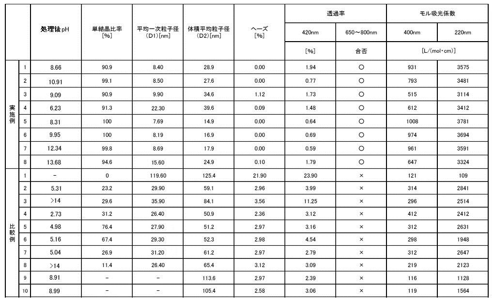
上記の各表及び図13~図15に示されたように、透過率は、単結晶比率、平均一次粒子径及び二次粒子径(体積平均粒子径)との関係において、上述の発明の概要及び発明を実施するための形態にて示した関係を示すことが裏付けられたものである。
上記の各表及び図16~図18に示されたように、波長400nmの光線に対するモル吸光係数は、単結晶比率、平均一次粒子径及び二次粒子径(体積平均粒子径)との関係において、上述の発明の概要及び発明を実施するための形態にて示した関係を示すことが裏付けられたものである。
上記の各表及び図19~図21に示されたように、波長220nmの光線に対するモル吸光係数は、単結晶比率、平均一次粒子径及び二次粒子径(体積平均粒子径)との関係において、上述の発明の概要及び発明を実施するための形態にて示した関係を示すことが裏付けられたものである。
上記の各表及び図22~図24に示されたように、工程(a)又は工程(a―2)の処理後のpHは、単結晶比率、平均一次粒子径及び二次粒子径(体積平均粒子径)との関係において、上述の発明の概要及び発明を実施するための形態にて示した関係を示すことが裏付けられたものである。 As shown in each of the above tables and FIGS. 10 to 12, the haze value is a summary of the above-described invention in relation to the single crystal ratio, the average primary particle diameter, and the secondary particle diameter (volume average particle diameter). And it is supported that the relationship shown in the embodiment for carrying out the invention is shown.
As shown in the above tables and FIGS. 13 to 15, the transmittance is related to the single crystal ratio, the average primary particle diameter, and the secondary particle diameter (volume average particle diameter). And it is supported that the relationship shown in the embodiment for carrying out the invention is shown.
As shown in the above tables and FIGS. 16 to 18, the molar extinction coefficient with respect to light having a wavelength of 400 nm is related to the single crystal ratio, the average primary particle size, and the secondary particle size (volume average particle size). It is confirmed that the above-described outline and the relationship shown in the mode for carrying out the invention are shown.
As shown in each of the above tables and FIGS. 19 to 21, the molar extinction coefficient for light having a wavelength of 220 nm is related to the single crystal ratio, the average primary particle diameter, and the secondary particle diameter (volume average particle diameter). It is confirmed that the above-described outline and the relationship shown in the mode for carrying out the invention are shown.
As shown in the above tables and FIGS. 22 to 24, the pH after the treatment in the step (a) or the step (a-2) is the single crystal ratio, the average primary particle size and the secondary particle size (volume). In relation to the average particle diameter), it is supported that the relation shown in the outline of the invention and the embodiment for carrying out the invention is shown.
2 第2処理用面
10 第1処理用部
11 第1ホルダ
20 第2処理用部
21 第2ホルダ
d1 第1導入部
d2 第2導入部
d20 開口部 DESCRIPTION OF
Claims (18)
- 少なくともFe3+イオンを含む酸化鉄原料流体と、少なくとも塩基性物質を含む酸化鉄析出流体とをマイクロリアクターを用いて混合させて酸化鉄の微粒子を析出させる工程(a)と、
上記析出させた酸化鉄の微粒子を分散媒に分散させて酸化鉄微粒子分散体を得る工程(b)と
を少なくとも含む紫外線防御剤組成物の製造方法であり、
上記酸化鉄微粒子分散体のヘーズ値が2.0%以下であり、かつ上記酸化鉄微粒子分散体の波長200~420nmの光線の透過率が2.0%以下であることを特徴とする紫外線防御剤組成物の製造方法。 A step (a) of mixing fine particles of iron oxide by mixing an iron oxide raw material fluid containing at least Fe 3+ ions and an iron oxide precipitation fluid containing at least a basic substance using a microreactor;
A method of producing an ultraviolet protective composition comprising at least a step (b) of dispersing the precipitated iron oxide fine particles in a dispersion medium to obtain an iron oxide fine particle dispersion,
UV protection, wherein the iron oxide fine particle dispersion has a haze value of 2.0% or less, and the iron oxide fine particle dispersion has a light transmittance of 200% to 420 nm of 2.0% or less. A method for producing an agent composition. - 上記酸化鉄微粒子分散体の波長650~800nmの光線の透過率が80%以上であることを特徴とする請求項1に記載の紫外線防御剤組成物の製造方法。 2. The method for producing an ultraviolet protective composition according to claim 1, wherein the iron oxide fine particle dispersion has a light transmittance of 80% or more at a wavelength of 650 to 800 nm.
- 上記酸化鉄の微粒子の一次粒子径が25nm未満であることを特徴とする請求項1または2に記載の紫外線防御剤組成物の製造方法。 The method for producing an ultraviolet protective composition according to claim 1 or 2, wherein the primary particle diameter of the iron oxide fine particles is less than 25 nm.
- 上記酸化鉄の微粒子の二次粒子径が50nm以下であることを特徴とする請求項1~3の何れかに記載の紫外線防御剤組成物の製造方法。 The method for producing an ultraviolet protective composition according to any one of claims 1 to 3, wherein the iron oxide fine particles have a secondary particle diameter of 50 nm or less.
- 上記酸化鉄微粒子分散体の波長400nmの光線に対するモル吸光係数が500L/(mol・cm)以上であり、波長220nmの光線に対するモル吸光係数が3000L/(mol・cm)以上であることを特徴とする請求項1~4の何れかに記載の紫外線防御剤組成物の製造方法。 The iron oxide fine particle dispersion has a molar extinction coefficient with respect to light having a wavelength of 400 nm of 500 L / (mol · cm) or more and a molar extinction coefficient with respect to light having a wavelength of 220 nm of 3000 L / (mol · cm) or more. The method for producing an ultraviolet protective composition according to any one of claims 1 to 4.
- 上記酸化鉄の微粒子が、略球形の酸化鉄微粒子を含むことを特徴とする請求項1~5の何れかに記載の紫外線防御剤組成物の製造方法。 6. The method for producing an ultraviolet protective composition according to claim 1, wherein the iron oxide fine particles include substantially spherical iron oxide fine particles.
- 上記酸化鉄の微粒子が、単結晶の酸化鉄微粒子を含むことを特徴とする請求項1~6の何れかに記載の紫外線防御剤組成物の製造方法。 The method for producing an ultraviolet protective composition according to any one of claims 1 to 6, wherein the iron oxide fine particles include single crystal iron oxide fine particles.
- 上記酸化鉄が、α-ヘマタイトであることを特徴とする請求項1~7の何れかに記載の紫外線防御剤組成物の製造方法。 The method for producing an ultraviolet protective composition according to any one of claims 1 to 7, wherein the iron oxide is α-hematite.
- 上記マイクロリアクターとして、接近および離反可能に互いに対向して配設され、少なくとも一方が他方に対して相対的に回転する第1処理用面と第2処理用面とを備えた流体処理装置を用い、
上記酸化鉄原料流体と上記酸化鉄析出流体との少なくとも2種類の被処理流体を、上記第1処理用面と上記第2処理用面との間に導入し、
上記第1処理用面と上記第2処理用面との間に付与される上記被処理流体の導入圧力により、上記第1処理用面と上記第2処理用面とを離反させる方向に作用する離反力を発生させ、上記第1処理用面と上記第2処理用面同士が互いに接近する方向に加えられる力と前記離反力との圧力バランスによって、第1処理用面と第2処理用面との間を微小な間隔に保ち、
上記少なくとも2つの被処理流体を、上記微小な間隔に保たれた上記第1処理用面と上記第2処理用面との間で合流させ、上記第1処理用面と上記第2処理用面との間を通過させることによって、薄膜流体を形成させ、
上記薄膜流体中で上記被処理流体同士を混合させて上記酸化鉄の微粒子を析出させる工程を行うことを特徴とする、請求項1~8の何れかに記載の紫外線防御剤組成物の製造方法。 As the microreactor, a fluid processing apparatus provided with a first processing surface and a second processing surface, which are arranged to face each other so as to be able to approach and separate from each other and at least one of which rotates relative to the other, is used. ,
Introducing at least two kinds of fluids to be treated, the iron oxide raw material fluid and the iron oxide deposition fluid, between the first processing surface and the second processing surface;
The introduction pressure of the fluid to be treated applied between the first processing surface and the second processing surface acts in a direction to separate the first processing surface and the second processing surface. A first processing surface and a second processing surface are generated by a pressure balance between a force generated in the direction in which the first processing surface and the second processing surface approach each other and a separation force is generated. Keep a small gap between
The at least two fluids to be processed are merged between the first processing surface and the second processing surface, which are kept at a minute interval, and the first processing surface and the second processing surface. A thin film fluid is formed by passing between
9. The method for producing an ultraviolet protective composition according to claim 1, wherein a step of mixing the fluids to be treated in the thin film fluid to precipitate the iron oxide fine particles is performed. . - 上記処理用面間で混合される上記酸化鉄原料流体を、上記酸化鉄原料流体の標準沸点以上として処理用面間に導入することを特徴とする請求項9に記載の紫外線防御剤組成物の製造方法。 10. The ultraviolet protective composition according to claim 9, wherein the iron oxide raw material fluid mixed between the processing surfaces is introduced between the processing surfaces at a normal boiling point or higher of the iron oxide raw material fluid. Production method.
- 上記被処理流体を上記処理用面間より吐出させた後であって上記工程(b)を行う前に、上記吐出させた上記被処理流体に対して更に撹拌処理を行う工程(a―2)を含むことを特徴とする請求項9又は10に記載の紫外線防御剤組成物の製造方法。 Step (a-2) of further stirring the discharged fluid to be processed after discharging the fluid to be processed from between the processing surfaces and before performing the step (b). The manufacturing method of the ultraviolet protective agent composition of Claim 9 or 10 characterized by the above-mentioned.
- 上記工程(a)にて上記吐出させた上記被処理流体のpHを6~14とすることを特徴とする請求項9~11の何れかに記載の紫外線防御剤組成物の製造方法。 12. The method for producing an ultraviolet protective composition according to claim 9, wherein the pH of the fluid to be treated discharged in the step (a) is 6 to 14.
- 上記工程(a―2)で得られた流体のpHを6~14とすることを特徴とする請求項11に記載の紫外線防御剤組成物の製造方法。 12. The method for producing an ultraviolet protective composition according to claim 11, wherein the pH of the fluid obtained in the step (a-2) is 6 to 14.
- 上記酸化鉄原料流体と上記酸化鉄析出流体との双方の上記被処理流体の上記導入圧力を、標準気圧を超えるものとし、
上記処理用面間に導入する上記酸化鉄原料流体の温度を、上記酸化鉄原料流体の標準沸点よりも高く且つ前記導入圧力下での沸点よりも低い温度とすることを特徴とする請求項9~13の何れかに記載の紫外線防御剤組成物の製造方法。 The introduction pressure of the treated fluid of both the iron oxide raw material fluid and the iron oxide deposition fluid shall exceed the standard atmospheric pressure,
The temperature of the iron oxide raw material fluid introduced between the processing surfaces is higher than the normal boiling point of the iron oxide raw material fluid and lower than the boiling point under the introduction pressure. 14. A method for producing an ultraviolet protection composition according to any one of items 13 to 13. - 上記請求項1~14の何れかに記載の紫外線防御剤組成物の製造方法によって得られた紫外線防御剤組成物。 15. An ultraviolet protective composition obtained by the method for producing an ultraviolet protective composition according to any one of claims 1 to 14.
- 少なくともFe3+イオンを含む酸化鉄原料流体と、少なくとも塩基性物質を含む酸化鉄析出流体とをマイクロリアクターを用いて混合させて酸化鉄の微粒子を析出させ、上記析出させた酸化鉄の微粒子を分散媒に分散させて得られた紫外線防御剤組成物であって、
上記酸化鉄の微粒子の一次粒子径が25nm未満であり、且つ、上記酸化鉄の微粒子の90%以上が単結晶化されたものであり、
上記酸化鉄微粒子分散体のヘーズ値が2.0%以下であり、且つ、上記酸化鉄微粒子分散体の波長200~420nmの光線の透過率が2.0%以下であることを特徴とする紫外線防御剤組成物。 An iron oxide raw material fluid containing at least Fe 3+ ions and an iron oxide precipitation fluid containing at least a basic substance are mixed using a microreactor to precipitate fine particles of iron oxide, and the precipitated fine particles of iron oxide are dispersed. An ultraviolet protection composition obtained by dispersing in a medium,
The primary particle diameter of the iron oxide fine particles is less than 25 nm, and 90% or more of the iron oxide fine particles are single-crystallized,
An ultraviolet ray characterized in that the iron oxide fine particle dispersion has a haze value of 2.0% or less and the iron oxide fine particle dispersion has a light transmittance of 2.0% or less at a wavelength of 200 to 420 nm. Protective agent composition. - 上記酸化鉄の微粒子は、
上記マイクロリアクターとして、接近および離反可能に互いに対向して配設され、少なくとも一方が他方に対して相対的に回転する第1処理用面と第2処理用面とを備えた流体処理装置を用い、
上記酸化鉄原料流体と上記酸化鉄析出流体との少なくとも2種類の被処理流体を、上記第1処理用面と上記第2処理用面との間に導入し、
上記第1処理用面と上記第2処理用面との間に付与される上記被処理流体の導入圧力により、上記第1処理用面と上記第2処理用面とを離反させる方向に作用する離反力を発生させ、上記第1処理用面と上記第2処理用面同士が互いに接近する方向に加えられる力と前記離反力との圧力バランスによって、第1処理用面と第2処理用面との間を微小な間隔に保ち、
上記少なくとも2つの被処理流体を、上記微小な間隔に保たれた上記第1処理用面と上記第2処理用面との間で合流させ、上記第1処理用面と上記第2処理用面との間を通過させることによって、薄膜流体を形成させ、
上記薄膜流体中で上記被処理流体同士を混合させて上記酸化鉄の微粒子を析出させ、上記第1処理用面と上記第2処理用面との間から上記被処理流体を吐出させ、上記吐出させた上記被処理流体のpHを6~14とすることにより得られた微粒子であることを特徴とする請求項16に記載の紫外線防御剤組成物。 The fine particles of iron oxide
As the microreactor, a fluid processing apparatus provided with a first processing surface and a second processing surface, which are arranged to face each other so as to be able to approach and separate from each other and at least one of which rotates relative to the other, is used. ,
Introducing at least two kinds of fluids to be treated, the iron oxide raw material fluid and the iron oxide deposition fluid, between the first processing surface and the second processing surface;
The introduction pressure of the fluid to be treated applied between the first processing surface and the second processing surface acts in a direction to separate the first processing surface and the second processing surface. A first processing surface and a second processing surface are generated by a pressure balance between a force generated in the direction in which the first processing surface and the second processing surface approach each other and a separation force is generated. Keep a small gap between
The at least two fluids to be processed are merged between the first processing surface and the second processing surface, which are kept at a minute interval, and the first processing surface and the second processing surface. A thin film fluid is formed by passing between
In the thin film fluid, the fluids to be treated are mixed to precipitate fine particles of the iron oxide, the fluid to be treated is discharged from between the first processing surface and the second processing surface, and the discharge The ultraviolet protective composition according to claim 16, wherein the composition is a fine particle obtained by adjusting the pH of the treated fluid to 6 to 14. - 上記酸化鉄の微粒子は、
上記マイクロリアクターとして、接近および離反可能に互いに対向して配設され、少なくとも一方が他方に対して相対的に回転する第1処理用面と第2処理用面とを備えた流体処理装置を用い、
上記酸化鉄原料流体と上記酸化鉄析出流体との少なくとも2種類の被処理流体を、上記第1処理用面と上記第2処理用面との間に導入し、
上記第1処理用面と上記第2処理用面との間に付与される上記被処理流体の導入圧力により、上記第1処理用面と上記第2処理用面とを離反させる方向に作用する離反力を発生させ、上記第1処理用面と上記第2処理用面同士が互いに接近する方向に加えられる力と前記離反力との圧力バランスによって、第1処理用面と第2処理用面との間を微小な間隔に保ち、
上記少なくとも2つの被処理流体を、上記微小な間隔に保たれた上記第1処理用面と上記第2処理用面との間で合流させ、上記第1処理用面と上記第2処理用面との間を通過させることによって、薄膜流体を形成させ、
上記薄膜流体中で上記被処理流体同士を混合させて上記酸化鉄の微粒子を析出させ、上記第1処理用面と上記第2処理用面との間から上記被処理流体を吐出させ、
上記吐出させた上記被処理流体に対して更に撹拌処理を行い、上記撹拌処理後の被処理流体のpHを6~14とすることにより得られた微粒子であることを特徴とする請求項16に記載の紫外線防御剤組成物。 The fine particles of iron oxide
As the microreactor, a fluid processing apparatus provided with a first processing surface and a second processing surface, which are arranged to face each other so as to be able to approach and separate from each other and at least one of which rotates relative to the other, is used. ,
Introducing at least two kinds of fluids to be treated, the iron oxide raw material fluid and the iron oxide deposition fluid, between the first processing surface and the second processing surface;
The introduction pressure of the fluid to be treated applied between the first processing surface and the second processing surface acts in a direction to separate the first processing surface and the second processing surface. A first processing surface and a second processing surface are generated by a pressure balance between a force generated in the direction in which the first processing surface and the second processing surface approach each other and a separation force is generated. Keep a small gap between
The at least two fluids to be processed are merged between the first processing surface and the second processing surface, which are kept at a minute interval, and the first processing surface and the second processing surface. A thin film fluid is formed by passing between
Mixing the fluids to be treated in the thin film fluid to precipitate the iron oxide fine particles, and discharging the fluid to be treated from between the first processing surface and the second processing surface;
17. The fine particles obtained by further stirring the discharged fluid to be treated and adjusting the pH of the fluid to be treated after the stirring to 6 to 14. The ultraviolet protective composition as described.
Priority Applications (6)
| Application Number | Priority Date | Filing Date | Title |
|---|---|---|---|
| EP16814484.8A EP3315575A4 (en) | 2015-06-26 | 2016-06-24 | Method for producing ultraviolet protective agent composition, and ultraviolet protective agent composition obtained thereby |
| JP2016567963A JP6113938B1 (en) | 2015-06-26 | 2016-06-24 | Method for producing UV protection composition and UV protection composition obtained thereby |
| KR1020177031744A KR102058346B1 (en) | 2015-06-26 | 2016-06-24 | Method for producing sunscreen composition and sunscreen composition obtained thereby |
| CN201680021992.3A CN107532064B (en) | 2015-06-26 | 2016-06-24 | Method for producing ultraviolet protective agent composition and ultraviolet protective agent composition obtained by the method |
| US15/559,342 US11629063B2 (en) | 2015-06-26 | 2016-06-24 | Method of producing ultraviolet protective agent composition, and ultraviolet protective agent composition obtained thereby |
| MX2017013891A MX2017013891A (en) | 2015-06-26 | 2016-06-24 | Method for producing ultraviolet protective agent composition, and ultraviolet protective agent composition obtained thereby. |
Applications Claiming Priority (2)
| Application Number | Priority Date | Filing Date | Title |
|---|---|---|---|
| JP2015129279 | 2015-06-26 | ||
| JP2015-129279 | 2015-06-26 |
Publications (1)
| Publication Number | Publication Date |
|---|---|
| WO2016208715A1 true WO2016208715A1 (en) | 2016-12-29 |
Family
ID=57585073
Family Applications (1)
| Application Number | Title | Priority Date | Filing Date |
|---|---|---|---|
| PCT/JP2016/068806 WO2016208715A1 (en) | 2015-06-26 | 2016-06-24 | Method for producing ultraviolet protective agent composition, and ultraviolet protective agent composition obtained thereby |
Country Status (7)
| Country | Link |
|---|---|
| US (1) | US11629063B2 (en) |
| EP (1) | EP3315575A4 (en) |
| JP (2) | JP6113938B1 (en) |
| KR (1) | KR102058346B1 (en) |
| CN (1) | CN107532064B (en) |
| MX (1) | MX2017013891A (en) |
| WO (1) | WO2016208715A1 (en) |
Families Citing this family (3)
| Publication number | Priority date | Publication date | Assignee | Title |
|---|---|---|---|---|
| JP6823771B2 (en) * | 2015-07-14 | 2021-02-03 | エム・テクニック株式会社 | Method for producing oxide particles |
| EP3467061B1 (en) * | 2016-06-02 | 2021-12-08 | M. Technique Co., Ltd. | Ultraviolet and/or near-infrared blocking agent composition for transparent material |
| CN112175439B (en) * | 2020-08-27 | 2022-05-13 | 浙江正奇世荣科技有限公司 | Nano ferric oxide ultraviolet-proof additive and preparation method thereof |
Citations (4)
| Publication number | Priority date | Publication date | Assignee | Title |
|---|---|---|---|---|
| JPH02178219A (en) * | 1988-12-28 | 1990-07-11 | Catalysts & Chem Ind Co Ltd | Titanium oxide-iron oxide multiple sol, cosmetic compounded with the sol and production thereof |
| JP2008194563A (en) * | 2007-02-08 | 2008-08-28 | Sumitomo Metal Mining Co Ltd | Solar radiation barrier film and wavelength selection type barrier film |
| JP2008231164A (en) * | 2007-03-16 | 2008-10-02 | Sumitomo Metal Mining Co Ltd | Ultraviolet ray- and near-infrared light-shielding dispersion, and ultraviolet ray- and near-infrared light-shielding item |
| JP2013082621A (en) * | 2010-08-26 | 2013-05-09 | M Technique Co Ltd | Method for manufacturing isolatable oxide microparticle or hydroxide microparticle |
Family Cites Families (25)
| Publication number | Priority date | Publication date | Assignee | Title |
|---|---|---|---|---|
| JPS5147091B2 (en) | 1971-09-30 | 1976-12-13 | ||
| JPH02271925A (en) * | 1989-04-12 | 1990-11-06 | Showa Denko Kk | Production of transparent spheroidal fine iron oxide particles |
| JP2813674B2 (en) | 1990-09-01 | 1998-10-22 | エム・テクニック株式会社 | Stirrer and fluid stirring method |
| JPH05319832A (en) * | 1992-05-18 | 1993-12-03 | Showa Denko Kk | Polycarbonate coloring composition |
| JPH085398A (en) * | 1994-06-16 | 1996-01-12 | Tokyo Gas Co Ltd | Control system for gas meter |
| JPH09272815A (en) * | 1996-04-02 | 1997-10-21 | Merck Japan Kk | Composite metal oxide fine particle and production of the same |
| JPH10167946A (en) * | 1996-12-09 | 1998-06-23 | Fuji Shikiso Kk | Composition good in dispensibility and skin-protecting agent containing the same |
| DE10049803A1 (en) * | 2000-10-09 | 2002-04-18 | Bayer Ag | Composite particles used e.g. for pigmenting paint or plastics comprise unagglomerated primary pigment particles adhering to colorless carrier particles and separated from one another by a minimum distance |
| JP2005145805A (en) * | 2003-10-24 | 2005-06-09 | Toyo Ink Mfg Co Ltd | SURFACE TREATED alpha-FERRIC OXIDE AND METHOD OF MANUFACTURING THE SAME |
| CN1297478C (en) * | 2003-11-28 | 2007-01-31 | 上海家化联合股份有限公司 | Molecular sieve based nano composite anti-ultraviolet material, its preparation method and use |
| DE112006000365T5 (en) * | 2005-02-17 | 2008-01-17 | Idemitsu Kosan Co. Ltd. | Thermoplastic resin composition capable of absorbing light having a wavelength of 420 nm and a body molded therefrom |
| WO2008054874A2 (en) * | 2006-05-12 | 2008-05-08 | Brown University | Particles with high uniform loading of nanoparticles and methods of preparation thereof |
| JP5137503B2 (en) * | 2006-09-15 | 2013-02-06 | 株式会社日本触媒 | UV-cutting agent for cosmetics and cosmetics using the same |
| EP2094226A4 (en) * | 2006-11-17 | 2016-01-13 | Kobo Products Inc | Uv protective cosmetic product incorproating titanium dioxide and transparent iron oxide |
| JP2010527342A (en) * | 2007-05-18 | 2010-08-12 | ユニリーバー・ナームローゼ・ベンノートシヤープ | Monodisperse particles |
| CN102516809B (en) * | 2007-07-06 | 2015-04-01 | M技术株式会社 | Method for producing nanoparticles by forced ultra-thin film rotary processing |
| JP2009082902A (en) | 2007-07-06 | 2009-04-23 | M Technique Co Ltd | Nanoparticle production method using forced ultrathin film rotating treatment method |
| JP2009057419A (en) * | 2007-08-30 | 2009-03-19 | Sumitomo Metal Mining Co Ltd | Polycarbonate resin molded article and method for producing the same |
| CN101868316B (en) * | 2007-09-27 | 2012-06-20 | M技术株式会社 | Process for producing fine magnetic-substance particle, fine magnetic-substance particle obtained by the same, and process for producing magnetic fluid or magnetic-substance product |
| JP4359858B2 (en) * | 2007-11-09 | 2009-11-11 | エム・テクニック株式会社 | Method for producing titanium dioxide ultrafine particles |
| CA2781329A1 (en) * | 2009-11-20 | 2011-05-26 | Toda Kogyo Corporation | Magnetic iron oxide fine particles, and magnetic particle-containing water dispersion and process for producing the same |
| US9139737B1 (en) * | 2011-11-21 | 2015-09-22 | Nanophase Technologies Corporation | Multifunctional coated powders and high solids dispersions |
| US9962666B2 (en) | 2012-07-13 | 2018-05-08 | M. Technique Co., Ltd. | Stirrer |
| JP2014169234A (en) * | 2013-03-01 | 2014-09-18 | Yamaguchi Mica Co Ltd | Ultraviolet shielding agent and cosmetic containing it |
| US20150283552A1 (en) * | 2014-04-08 | 2015-10-08 | University Of Oregon | Magnetic plastic or fiberboard waste separation |
-
2016
- 2016-06-24 CN CN201680021992.3A patent/CN107532064B/en active Active
- 2016-06-24 US US15/559,342 patent/US11629063B2/en active Active
- 2016-06-24 MX MX2017013891A patent/MX2017013891A/en unknown
- 2016-06-24 JP JP2016567963A patent/JP6113938B1/en active Active
- 2016-06-24 EP EP16814484.8A patent/EP3315575A4/en active Pending
- 2016-06-24 KR KR1020177031744A patent/KR102058346B1/en active IP Right Grant
- 2016-06-24 WO PCT/JP2016/068806 patent/WO2016208715A1/en active Application Filing
-
2017
- 2017-03-06 JP JP2017041321A patent/JP2017145252A/en active Pending
Patent Citations (4)
| Publication number | Priority date | Publication date | Assignee | Title |
|---|---|---|---|---|
| JPH02178219A (en) * | 1988-12-28 | 1990-07-11 | Catalysts & Chem Ind Co Ltd | Titanium oxide-iron oxide multiple sol, cosmetic compounded with the sol and production thereof |
| JP2008194563A (en) * | 2007-02-08 | 2008-08-28 | Sumitomo Metal Mining Co Ltd | Solar radiation barrier film and wavelength selection type barrier film |
| JP2008231164A (en) * | 2007-03-16 | 2008-10-02 | Sumitomo Metal Mining Co Ltd | Ultraviolet ray- and near-infrared light-shielding dispersion, and ultraviolet ray- and near-infrared light-shielding item |
| JP2013082621A (en) * | 2010-08-26 | 2013-05-09 | M Technique Co Ltd | Method for manufacturing isolatable oxide microparticle or hydroxide microparticle |
Non-Patent Citations (1)
| Title |
|---|
| See also references of EP3315575A4 * |
Also Published As
| Publication number | Publication date |
|---|---|
| CN107532064B (en) | 2021-03-16 |
| KR102058346B1 (en) | 2019-12-23 |
| JP6113938B1 (en) | 2017-04-12 |
| KR20170132322A (en) | 2017-12-01 |
| EP3315575A1 (en) | 2018-05-02 |
| MX2017013891A (en) | 2018-03-15 |
| EP3315575A4 (en) | 2019-01-09 |
| JP2017145252A (en) | 2017-08-24 |
| CN107532064A (en) | 2018-01-02 |
| US20180111842A1 (en) | 2018-04-26 |
| JPWO2016208715A1 (en) | 2017-06-29 |
| US11629063B2 (en) | 2023-04-18 |
Similar Documents
| Publication | Publication Date | Title |
|---|---|---|
| JP5794582B2 (en) | Method for producing separable oxide fine particles or hydroxide fine particles | |
| JP5851755B2 (en) | Fine particle dispersion method and dispersion | |
| JP6771773B2 (en) | Metal oxide particles and their manufacturing method | |
| JP2013082621A5 (en) | ||
| JP6113938B1 (en) | Method for producing UV protection composition and UV protection composition obtained thereby | |
| JP4840835B2 (en) | Method for producing nanoparticles | |
| US10196267B2 (en) | Method of producing oxide particles | |
| JP2006342348A (en) | Low energy method for preparing passive inorganic nanoparticle | |
| Guzman et al. | Effect of the concentration and the type of dispersant on the synthesis of copper oxide nanoparticles and their potential antimicrobial applications | |
| WO2016098777A1 (en) | Composite phthalocyanine microparticles and method for producing same | |
| JP2010168254A (en) | Ultraviolet screening agent, cosmetic, and micro-acicular zinc oxide | |
| JP6035500B1 (en) | Silicon oxide coated iron oxide composition for paints | |
| Matei et al. | Interaction of oxide nanoparticles with surface-active agents |
Legal Events
| Date | Code | Title | Description |
|---|---|---|---|
| ENP | Entry into the national phase |
Ref document number: 2016567963 Country of ref document: JP Kind code of ref document: A |
|
| 121 | Ep: the epo has been informed by wipo that ep was designated in this application |
Ref document number: 16814484 Country of ref document: EP Kind code of ref document: A1 |
|
| WWE | Wipo information: entry into national phase |
Ref document number: 15559342 Country of ref document: US |
|
| WWE | Wipo information: entry into national phase |
Ref document number: MX/A/2017/013891 Country of ref document: MX |
|
| ENP | Entry into the national phase |
Ref document number: 20177031744 Country of ref document: KR Kind code of ref document: A |
|
| NENP | Non-entry into the national phase |
Ref country code: DE |
|
| WWE | Wipo information: entry into national phase |
Ref document number: 2016814484 Country of ref document: EP |