WO2016208521A1 - Integrated multiple valve manifold - Google Patents
Integrated multiple valve manifold Download PDFInfo
- Publication number
- WO2016208521A1 WO2016208521A1 PCT/JP2016/068197 JP2016068197W WO2016208521A1 WO 2016208521 A1 WO2016208521 A1 WO 2016208521A1 JP 2016068197 W JP2016068197 W JP 2016068197W WO 2016208521 A1 WO2016208521 A1 WO 2016208521A1
- Authority
- WO
- WIPO (PCT)
- Prior art keywords
- hole
- valve
- manifold
- fluid supply
- fluid
- Prior art date
Links
Images


Classifications
-
- F—MECHANICAL ENGINEERING; LIGHTING; HEATING; WEAPONS; BLASTING
- F16—ENGINEERING ELEMENTS AND UNITS; GENERAL MEASURES FOR PRODUCING AND MAINTAINING EFFECTIVE FUNCTIONING OF MACHINES OR INSTALLATIONS; THERMAL INSULATION IN GENERAL
- F16K—VALVES; TAPS; COCKS; ACTUATING-FLOATS; DEVICES FOR VENTING OR AERATING
- F16K11/00—Multiple-way valves, e.g. mixing valves; Pipe fittings incorporating such valves
- F16K11/10—Multiple-way valves, e.g. mixing valves; Pipe fittings incorporating such valves with two or more closure members not moving as a unit
- F16K11/20—Multiple-way valves, e.g. mixing valves; Pipe fittings incorporating such valves with two or more closure members not moving as a unit operated by separate actuating members
- F16K11/22—Multiple-way valves, e.g. mixing valves; Pipe fittings incorporating such valves with two or more closure members not moving as a unit operated by separate actuating members with an actuating member for each valve, e.g. interconnected to form multiple-way valves
-
- F—MECHANICAL ENGINEERING; LIGHTING; HEATING; WEAPONS; BLASTING
- F15—FLUID-PRESSURE ACTUATORS; HYDRAULICS OR PNEUMATICS IN GENERAL
- F15B—SYSTEMS ACTING BY MEANS OF FLUIDS IN GENERAL; FLUID-PRESSURE ACTUATORS, e.g. SERVOMOTORS; DETAILS OF FLUID-PRESSURE SYSTEMS, NOT OTHERWISE PROVIDED FOR
- F15B13/00—Details of servomotor systems ; Valves for servomotor systems
- F15B13/02—Fluid distribution or supply devices characterised by their adaptation to the control of servomotors
- F15B13/06—Fluid distribution or supply devices characterised by their adaptation to the control of servomotors for use with two or more servomotors
- F15B13/08—Assemblies of units, each for the control of a single servomotor only
- F15B13/0803—Modular units
- F15B13/0832—Modular valves
- F15B13/0842—Monoblock type valves, e.g. with multiple valve spools in a common housing
-
- F—MECHANICAL ENGINEERING; LIGHTING; HEATING; WEAPONS; BLASTING
- F15—FLUID-PRESSURE ACTUATORS; HYDRAULICS OR PNEUMATICS IN GENERAL
- F15B—SYSTEMS ACTING BY MEANS OF FLUIDS IN GENERAL; FLUID-PRESSURE ACTUATORS, e.g. SERVOMOTORS; DETAILS OF FLUID-PRESSURE SYSTEMS, NOT OTHERWISE PROVIDED FOR
- F15B13/00—Details of servomotor systems ; Valves for servomotor systems
- F15B13/02—Fluid distribution or supply devices characterised by their adaptation to the control of servomotors
- F15B13/06—Fluid distribution or supply devices characterised by their adaptation to the control of servomotors for use with two or more servomotors
- F15B13/08—Assemblies of units, each for the control of a single servomotor only
- F15B13/0803—Modular units
- F15B13/0807—Manifolds
- F15B13/0814—Monoblock manifolds
-
- F—MECHANICAL ENGINEERING; LIGHTING; HEATING; WEAPONS; BLASTING
- F15—FLUID-PRESSURE ACTUATORS; HYDRAULICS OR PNEUMATICS IN GENERAL
- F15B—SYSTEMS ACTING BY MEANS OF FLUIDS IN GENERAL; FLUID-PRESSURE ACTUATORS, e.g. SERVOMOTORS; DETAILS OF FLUID-PRESSURE SYSTEMS, NOT OTHERWISE PROVIDED FOR
- F15B13/00—Details of servomotor systems ; Valves for servomotor systems
- F15B13/02—Fluid distribution or supply devices characterised by their adaptation to the control of servomotors
- F15B13/06—Fluid distribution or supply devices characterised by their adaptation to the control of servomotors for use with two or more servomotors
- F15B13/08—Assemblies of units, each for the control of a single servomotor only
- F15B13/0803—Modular units
- F15B13/0807—Manifolds
- F15B13/0817—Multiblock manifolds
-
- F—MECHANICAL ENGINEERING; LIGHTING; HEATING; WEAPONS; BLASTING
- F15—FLUID-PRESSURE ACTUATORS; HYDRAULICS OR PNEUMATICS IN GENERAL
- F15B—SYSTEMS ACTING BY MEANS OF FLUIDS IN GENERAL; FLUID-PRESSURE ACTUATORS, e.g. SERVOMOTORS; DETAILS OF FLUID-PRESSURE SYSTEMS, NOT OTHERWISE PROVIDED FOR
- F15B13/00—Details of servomotor systems ; Valves for servomotor systems
- F15B13/02—Fluid distribution or supply devices characterised by their adaptation to the control of servomotors
- F15B13/06—Fluid distribution or supply devices characterised by their adaptation to the control of servomotors for use with two or more servomotors
- F15B13/08—Assemblies of units, each for the control of a single servomotor only
- F15B13/0803—Modular units
- F15B13/0871—Channels for fluid
-
- F—MECHANICAL ENGINEERING; LIGHTING; HEATING; WEAPONS; BLASTING
- F16—ENGINEERING ELEMENTS AND UNITS; GENERAL MEASURES FOR PRODUCING AND MAINTAINING EFFECTIVE FUNCTIONING OF MACHINES OR INSTALLATIONS; THERMAL INSULATION IN GENERAL
- F16K—VALVES; TAPS; COCKS; ACTUATING-FLOATS; DEVICES FOR VENTING OR AERATING
- F16K11/00—Multiple-way valves, e.g. mixing valves; Pipe fittings incorporating such valves
- F16K11/02—Multiple-way valves, e.g. mixing valves; Pipe fittings incorporating such valves with all movable sealing faces moving as one unit
- F16K11/06—Multiple-way valves, e.g. mixing valves; Pipe fittings incorporating such valves with all movable sealing faces moving as one unit comprising only sliding valves, i.e. sliding closure elements
- F16K11/065—Multiple-way valves, e.g. mixing valves; Pipe fittings incorporating such valves with all movable sealing faces moving as one unit comprising only sliding valves, i.e. sliding closure elements with linearly sliding closure members
- F16K11/07—Multiple-way valves, e.g. mixing valves; Pipe fittings incorporating such valves with all movable sealing faces moving as one unit comprising only sliding valves, i.e. sliding closure elements with linearly sliding closure members with cylindrical slides
-
- F—MECHANICAL ENGINEERING; LIGHTING; HEATING; WEAPONS; BLASTING
- F16—ENGINEERING ELEMENTS AND UNITS; GENERAL MEASURES FOR PRODUCING AND MAINTAINING EFFECTIVE FUNCTIONING OF MACHINES OR INSTALLATIONS; THERMAL INSULATION IN GENERAL
- F16K—VALVES; TAPS; COCKS; ACTUATING-FLOATS; DEVICES FOR VENTING OR AERATING
- F16K27/00—Construction of housing; Use of materials therefor
- F16K27/003—Housing formed from a plurality of the same valve elements
-
- F—MECHANICAL ENGINEERING; LIGHTING; HEATING; WEAPONS; BLASTING
- F16—ENGINEERING ELEMENTS AND UNITS; GENERAL MEASURES FOR PRODUCING AND MAINTAINING EFFECTIVE FUNCTIONING OF MACHINES OR INSTALLATIONS; THERMAL INSULATION IN GENERAL
- F16K—VALVES; TAPS; COCKS; ACTUATING-FLOATS; DEVICES FOR VENTING OR AERATING
- F16K27/00—Construction of housing; Use of materials therefor
- F16K27/04—Construction of housing; Use of materials therefor of sliding valves
- F16K27/041—Construction of housing; Use of materials therefor of sliding valves cylindrical slide valves
-
- F—MECHANICAL ENGINEERING; LIGHTING; HEATING; WEAPONS; BLASTING
- F16—ENGINEERING ELEMENTS AND UNITS; GENERAL MEASURES FOR PRODUCING AND MAINTAINING EFFECTIVE FUNCTIONING OF MACHINES OR INSTALLATIONS; THERMAL INSULATION IN GENERAL
- F16K—VALVES; TAPS; COCKS; ACTUATING-FLOATS; DEVICES FOR VENTING OR AERATING
- F16K27/00—Construction of housing; Use of materials therefor
- F16K27/04—Construction of housing; Use of materials therefor of sliding valves
- F16K27/048—Electromagnetically actuated valves
-
- F—MECHANICAL ENGINEERING; LIGHTING; HEATING; WEAPONS; BLASTING
- F16—ENGINEERING ELEMENTS AND UNITS; GENERAL MEASURES FOR PRODUCING AND MAINTAINING EFFECTIVE FUNCTIONING OF MACHINES OR INSTALLATIONS; THERMAL INSULATION IN GENERAL
- F16K—VALVES; TAPS; COCKS; ACTUATING-FLOATS; DEVICES FOR VENTING OR AERATING
- F16K3/00—Gate valves or sliding valves, i.e. cut-off apparatus with closing members having a sliding movement along the seat for opening and closing
- F16K3/30—Details
- F16K3/314—Forms or constructions of slides; Attachment of the slide to the spindle
-
- F—MECHANICAL ENGINEERING; LIGHTING; HEATING; WEAPONS; BLASTING
- F16—ENGINEERING ELEMENTS AND UNITS; GENERAL MEASURES FOR PRODUCING AND MAINTAINING EFFECTIVE FUNCTIONING OF MACHINES OR INSTALLATIONS; THERMAL INSULATION IN GENERAL
- F16K—VALVES; TAPS; COCKS; ACTUATING-FLOATS; DEVICES FOR VENTING OR AERATING
- F16K31/00—Actuating devices; Operating means; Releasing devices
- F16K31/12—Actuating devices; Operating means; Releasing devices actuated by fluid
- F16K31/122—Actuating devices; Operating means; Releasing devices actuated by fluid the fluid acting on a piston
Definitions
- the present invention relates to a multiple integral type manifold valve in which a plurality of valve mechanisms are integrally incorporated in one manifold.
- a plurality of valves are often mounted in a collective state on a movable part such as an industrial robot or an article conveying device.
- the manifold valve is used.
- the conventional manifold valve is quite large and heavy, so that not only a large installation space is required, but also the mechanical and energy burdens on the movable part are large. there were. For this reason, the appearance of a manifold valve that is as small and light as possible is desired from the viewpoint of reducing the mechanical burden on the movable part and saving energy.
- Patent Document 2 discloses a valve system in which a plurality of valve elements are incorporated in one valve body.
- the valve element is mounted in a mounting hole formed in the valve body, which can be said to be smaller and lighter than the manifold valve disclosed in Patent Document 1.
- this valve system forms an oil passage between the valve body and the oil passage forming member by fixing an oil passage forming member separate from the valve body on both sides of the valve body.
- the lid body is overlapped and fixed on the outer surface of one oil passage forming member, and a joint for pipe connection is formed on the lid body, the formation method of the oil passage and the joint is complicated. It is hard to say that it is sufficiently small and lightweight.
- the technical problem of the present invention is to form a multi-unit integrated manifold valve that is smaller and lighter than conventional products by integrating a plurality of valve mechanisms into one manifold.
- the fluid supply hole and the fluid discharge hole are formed of an extruded material penetrating the inside, and the vertical direction which is the penetration direction of the fluid supply hole and the fluid discharge hole,
- a manifold having a lateral direction perpendicular to the direction and a vertical direction perpendicular to both the longitudinal direction and the lateral direction, penetrating the interior of the manifold in the lateral direction, and directly with both the fluid supply hole and the fluid discharge hole
- An output port a spool that is slidably inserted into the valve hole, and that switches a flow path connecting the output port with the fluid supply hole and the fluid discharge hole, and the spool.
- a pilot valve of an electromagnetic type which is mounted individually to one or both ends of each valve hole is provided.
- the fluid supply hole and the fluid discharge hole are formed at different positions in the vertical direction of the manifold, have a noncircular cross-sectional shape, and have a constant hole width in a part of the cross section.
- An elongated hole portion, and the elongated hole portion of the fluid supply hole and the elongated hole portion of the fluid discharge hole extend in opposite directions toward the vertical direction of the manifold, and It is desirable to cross each other from the upside down direction.
- the vertical length of the portion where the elongated hole portion of the fluid supply hole and the fluid discharge hole intersects each valve hole is smaller than the inner diameter of the valve hole, and the elongated hole portion of the fluid supply hole and the fluid discharge hole is An arc-shaped recess having a diameter larger than the inner diameter of the valve hole is formed concentrically with the valve hole at a position intersecting with each valve hole.
- the pilot valve is attached to a side surface of the manifold via an adapter plate, and the adapter plate includes a drive piston that abuts one end of the spool;
- a driving pressure chamber is provided for causing a pilot fluid to act on the driving piston, and the driving pressure chamber is connected to the fluid supply hole via the pilot valve.
- an end plate is attached to the other end of the valve hole in which the pilot valve is attached to only one end, and the other end of the spool is attached to the end plate.
- a return pressure chamber for causing a pilot fluid to act on the return piston, wherein the return piston has a smaller diameter than the drive piston, and the return pressure chamber is It always communicates with the fluid supply hole.
- a plurality of valve holes are formed in one manifold through which a fluid supply hole and a fluid discharge hole pass so as to cross the fluid supply hole and the fluid discharge hole directly, and a spool is inserted into each valve hole.
- a pilot valve or the like for driving the spool is attached to the manifold, it is possible to obtain a multiple integrated manifold valve that is smaller and lighter than the conventional product.
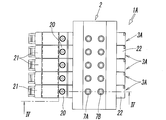
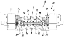
- FIG. 1 is a perspective view showing a first embodiment of a multiple integrated manifold valve according to the present invention, with a part of a valve mechanism disassembled. It is a top view of the completed product of the manifold valve of FIG.
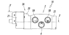
- FIG. 3 is a front view of FIG. 2.
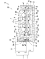
- FIG. 4 is a sectional view taken along line IV-IV in FIG. 2.
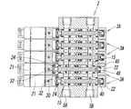
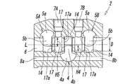
- FIG. 5 is a sectional view taken along line VV in FIG. 3.
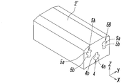
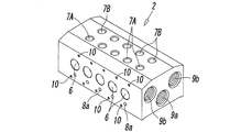
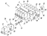
- It is a perspective view of the block body before forming a manifold. It is sectional drawing of FIG. It is a perspective view of the manifold formed by processing the block body of FIG. It is sectional drawing of FIG.
- FIGS. 1 to 5 show a first embodiment of a multi-unit integrated manifold valve according to the present invention.
- the manifold valve 1A of the first embodiment is formed as shown in FIGS.
- a plurality of valve mechanisms 3 ⁇ / b> A for controlling a pressure fluid such as compressed air are integrally incorporated in one manifold 2.
- the illustrated example is a five-unit manifold valve in which five sets of valve mechanisms 3A are incorporated in the manifold 2, and the five sets of valve mechanisms 3A are all single solenoid type five-port valves and have the same configuration. have.
- the manifold 2 is formed by performing necessary processing on a block body 2 ′ as shown in FIGS. 6 and 7, and the block body 2 ′ is made of an extruded metal (for example, an aluminum alloy). Manufactured) is cut to a length necessary to incorporate the required number of valve mechanisms 3A.
- the block body 2 ′ is preliminarily formed with fluid supply holes 4 and fluid discharge holes 5A and 5B. As shown in FIGS. 8 and 9, the block body 2 ′ includes a valve mechanism 3A to be incorporated.
- the manifold 2 is formed by forming a plurality of valve holes 6, output ports 7A and 7B, pilot supply holes 8a and 8b, pipe connection ports 9a and 9b, screw holes 10 and the like corresponding to the number.
- the block body 2 ′ includes a vertical direction (X direction) which is an extrusion direction of the extruded material, a horizontal direction (Y direction) orthogonal to the vertical direction, the vertical direction and the horizontal direction.
- the fluid supply hole 4 for supplying pressure fluid to all the valve mechanisms 3A and all the valves inside the block body 2 '.
- the two fluid discharge holes 5A and 5B for discharging the fluid discharged from the mechanism 3A to the outside penetrate straightly in the vertical direction.
- the fluid supply hole 4 is disposed at the lateral center of the block body 2 ′, and the two fluid discharge holes 5 ⁇ / b> A and 5 ⁇ / b> B are provided on both sides of the fluid supply hole 4. It is arranged.
- the fluid supply hole 4 and the fluid discharge holes 5A and 5B are formed at different positions in the vertical direction of the block body 2 ′, and the fluid supply hole 4 includes the two fluid discharge holes 5A. , 5B, and the two fluid discharge holes 5A, 5B are formed at the same position.
- the fluid supply hole 4 and the fluid discharge holes 5A and 5B are non-circular holes and have main hole portions 4a and 5a and long hole portions 4b and 5b.
- the cross-sectional shapes of the fluid discharge holes 5A and 5B are the same or symmetrical with each other.
- the main hole portion 4a of the fluid supply hole 4 is surrounded by an arc-shaped wall 11a that is a part of the virtual cylindrical surface C1 and two side walls 11b that extend radially from both ends of the arc-shaped wall 11a.
- the elongated hole portion 4b has a constant hole width W4 surrounded by an arcuate wall 11c that is a part of the virtual cylindrical surface C1 and two parallel side walls 11d. This is an elongated slot-like part.
- the arc-shaped wall 11a and the arc-shaped wall 11c are portions located on opposite sides of the virtual cylindrical surface C1 in the diametrical direction. Therefore, the main hole portion 4a and the long hole portion 4b are the virtual cylinder surfaces.
- the straight hole is continuous in the diameter direction of the surface C1, and the hole width W4 of the long hole portion 4b is narrower than the maximum hole width of the main hole portion 4a.
- the main hole portion 5a of the fluid discharge holes 5A and 5B is a portion surrounded by an arcuate wall 12a that is a part of the virtual cylindrical surface C2 and left and right side walls 12b that are connected to both ends of the arcuate wall 12a.
- the elongated hole portion 5b is an elongated elongated hole shape having a certain hole width W5 surrounded by an arcuate wall 12c that is a part of the virtual cylindrical surface C2 and two parallel side walls 12d. It is the part which did.
- the main hole portion 5a and the long hole portion 5b are continuous in the diameter direction of the virtual cylindrical surface C2.
- the arc-shaped wall 12a and the arc-shaped wall 12c are located on opposite sides of the virtual cylindrical surface C2 in the diameter direction.
- the virtual cylindrical surfaces C1 and C2 have the same diameter, the hole width W5 of the long hole portion 5b of the two fluid discharge holes 5A and 5B is equal to each other, and the hole width W4 of the long hole portion 4b of the fluid supply hole 4 Is formed to be equal to or smaller than the hole width W5 of the long hole portion 5b of the fluid discharge holes 5A and 5B.
- the long hole portion 4b of the fluid supply hole 4 and the long hole portion 5b of the fluid discharge holes 5A and 5B extend in the opposite direction and parallel to each other with the inside of the block body 2 'directed vertically. . That is, the long hole portion 4b of the fluid supply hole 4 extends upward in the block body 2 ', and the long hole portion 5b of the fluid discharge holes 5A and 5B extends in the block body 2'.
- the front end (lower end) of the long hole portion 4b of the fluid supply hole 4 and the front end (upper end) of the long hole portion 5b of the fluid discharge holes 5A and 5B extend upward and downward of the block body 2 ′. Occupies almost the same position in the direction.
- a plurality of the valve holes 6 are formed in the manifold 2 so as to penetrate the inside of the manifold 2 in the lateral direction.
- the plurality of valve holes 6 are arranged in parallel with each other at a predetermined interval at the same position in the vertical direction of the manifold 2, and the long hole portions 4 b of the fluid supply holes 4 and the fluid discharge holes 5 A and 5 B are provided.
- the fluid supply hole 4 and the fluid discharge holes 5A and 5B communicate with each other.
- the long hole portion 4b of the fluid supply hole 4 and the long hole portion 5b of the fluid discharge holes 5A and 5B intersect with the valve hole 6 from opposite directions.
- the long hole portion 4b of the fluid supply hole 4 intersects the valve hole 6 from the lower side of the valve hole 6, and the long hole portion 5b of the fluid discharge holes 5A and 5B is connected to the valve hole 6 by the valve. It intersects from the upper side of the hole 6.
- the length H5 in the vertical direction is smaller than the inner diameter D of the valve hole 6. Therefore, the position where the elongated hole portions 4b and 5b intersect with each valve hole 6 is larger than the inner diameter of the valve hole 6.
- the arc-shaped recess 14 is formed concentrically with the valve hole 6.
- valve hole 6 is formed at a position that directly intersects with the fluid supply hole 4 and the fluid discharge holes 5A and 5B, so that the valve hole 6 is formed with the fluid supply hole 4 and the fluid discharge holes 5A and 5B.
- the height of the manifold 2, that is, the width in the vertical direction can be significantly reduced compared to the case where it is formed at a position away from 5B in the vertical direction and communicated with each flow path through the communication hole.
- 1A can be miniaturized. Compared to connecting separately formed manifolds and valves, not only the overall size can be significantly reduced, but also there is no need for gaskets or connecting bolts, resulting in significant weight savings. Can be planned.
- valve hole 6 is formed so as to cross the long hole portions 4b and 5b of the fluid supply hole 4 and the fluid discharge holes 5A and 5B, so that the inside of the valve hole 6 as shown in FIGS.
- the side edge 17a of the valve seat 17 on which each of the seal members 16a-16d rides can be formed on a plane orthogonal to the central axis L of the valve hole 6 when the spool 15 inserted in the valve 15 is switched.
- valve holes 6 are provided.
- the number of valve holes 6 is not limited to five, and may be appropriately increased or decreased according to the number of valve mechanisms 3A to be incorporated. .
- a plurality of the output ports 7 ⁇ / b> A and 7 ⁇ / b> B that individually communicate with the plurality of valve holes 6 are provided.
- two output ports 7A and 7B are arranged for each valve hole 6 so as to be adjacent to the lateral direction of the manifold 2 along the valve hole 6, and one of the first output ports 7A is , Communicating with the valve hole 6 at a position between the fluid supply hole 4 and the first fluid discharge hole 5A, and the other second output port 7B is formed between the fluid supply hole 4 and the second fluid discharge hole 5B. It communicates with the valve hole 6 at a position in between.
- the output ports 7A and 7B may be formed on the lower surface of the manifold 2, or may be formed on both the upper surface and the lower surface. When the output ports 7A and 7B are formed on both the upper surface and the lower surface, the output ports 7A and 7B on one surface are selectively used, and the output ports 7A and 7B on the other surface are plugs or the like. It is blocked.
- the pipe connection ports 9a and 9b formed of circular screw holes for connecting pipes to both ends of the fluid supply hole 4 and the fluid discharge holes 5A and 5B are provided at both ends in the vertical direction of the manifold 2. Is formed concentrically with the virtual cylindrical surfaces C1 and C2, and is configured to be screwed into and connected to the pipe connection ports 9a and 9b. When a pipe is not connected to the pipe connection port 9a or 9b on one end side of the fluid supply hole 4 and the fluid discharge holes 5A and 5B, the pipe connection port 9a or 9b is closed with a plug.
- the inner diameters of the pipe connection ports 9a and 9b are the same as or larger than the diameters of the virtual cylindrical surfaces C1 and C2.
- the pilot supply holes 8 a and 8 b extend laterally in the manifold 2 starting from the fluid supply hole 4, and the tip of one of the first pilot supply holes 8 a is one of the manifolds 2. It opens to the side surface, and the tip of the other second pilot supply hole 8 b opens to the other side surface of the manifold 2.
- the spool 15 is slidably inserted into the valve hole 6 as shown in FIGS.
- a pilot valve 21 is attached to one end side of the valve hole 6 via an adapter plate 20, and an end plate 22 is attached to the other end side of the valve hole 6.
- the spool 15 has a first seal member 16a for opening and closing a flow path connecting the fluid supply hole 4 and the first output port 7A, and a flow path connecting the fluid supply hole 4 and the second output port 7B.
- a second seal member 16b that opens and closes
- a third seal member 16c that opens and closes a flow path connecting the first output port 7A and the first fluid discharge hole 5A, and the second output port 7B and the second fluid discharge. It has the 4th seal member 16d which opens and closes the flow path which connects hole 5B, and the 5th seal member 16e and the 6th seal member 16f which always close the both ends of the valve hole 6.
- the adapter plate 20 is a member having a block shape elongated in the vertical direction of the manifold 2, and has a drive piston 24 and a manual operation mechanism 25, and is screwed into the screw hole 10 on the side surface of the manifold 2.
- the pilot valve 21 is fixed on the outer surface of the adapter plate 20 with an attachment screw 28 screwed into a screw hole 27 of the adapter plate 20.
- the drive piston 24 is disposed in the piston chamber 30 of the adapter plate 20 so as to be slidable in the direction of the axis L via a lip-shaped seal member 31 attached to the outer periphery of the drive piston 24.
- a leg portion 24 a formed on an end surface facing the spool 15 abuts on the end surface of the spool 15, and the back surface of the driving piston 24 faces a driving pressure chamber 32 formed in the piston chamber 30. is doing.
- the driving pressure chamber 32 is operated from the pilot communication hole 33 through the lower half 34b of the operation element hole 34 of the manual operation mechanism 25, the pilot output hole 35, the pilot valve 21, the pilot input hole 36, and the operation of the manual operation mechanism 25.
- the sub-hole 34 is connected to the first pilot supply hole 8 a through the upper half 34 a and the pilot relay hole 37.
- a space 38 between the driving piston 24 and the end face of the spool 15 is open to the atmosphere through a through hole (not shown).
- the pilot valve 21 is a three-port solenoid valve.
- the pilot valve 21 When the pilot valve 21 is energized, the pilot input hole 36 and the pilot output hole 35 communicate with each other, so that the pilot valve 21 is connected to the first pilot supply hole 8a.
- the pilot fluid flows into the driving pressure chamber 32 from the pilot communication hole 33, the driving piston 24 moves rightward as shown in FIG. 4, and the spool 15 is switched to the first position.
- the fluid supply hole 4 and the first output port 7A communicate with each other
- the second output port 7B and the second fluid discharge hole 5B communicate with each other
- the fluid supply hole 4 and the second output port communicate with each other.
- the flow path connecting 7B is blocked by the second seal member 16b, and the flow path connecting the first output port 7A and the first fluid discharge hole 5A is blocked by the third seal member 16c.
- the pilot valve 21 When the pilot valve 21 is de-energized, the pilot fluid in the driving pressure chamber 32 is discharged through the pilot valve 21, so that the spool 15 and the driving piston 24 are provided on the end plate 22. It is pushed by the return piston 40 and moves to the left in FIG. 4 to occupy the return position. Details of this point will be described later.
- the manual operation mechanism 25 realizes the same state as when the pilot valve 21 is energized by manual operation of the operation element 41 at the time of a power failure or maintenance, and the operation element 41 is connected to the operation element hole 34. Is housed in such a manner that it can be pushed down, and is always urged upward by the force of the return spring 42 and normally occupies the non-operating position shown. At this time, the lower half portion 34b and the upper half portion 34a of the operating element hole 34 are blocked by an O-ring 43 attached to the outer periphery of the operating element 41. When the operating element 41 is pushed down from this state, the O-ring 43 moves downward through the pilot communication hole 33, so that the lower half part 34b and the upper half part 34a communicate with each other. The pilot fluid from the pilot supply hole 8a flows directly into the driving pressure chamber 32 from the pilot communication hole 33 through the operation hole 34, and the driving piston 24 operates.
- the end plate 22 attached to the other end side of the valve hole 6 is a block-like member which is vertically long like the adapter plate 20, and is similar to the adapter plate 20 on the side surface of the manifold 2.
- the mounting screw 45 is screwed into the screw hole to be fixed to the manifold 2.
- the return piston 40 is slidably disposed in the direction of the axis L via a lip-shaped seal member 47 attached to the outer periphery thereof.
- a leg portion 40 a formed on the end surface facing the spool 15 contacts the end surface of the spool 15, and the back surface of the return piston 40 faces a return pressure chamber 48 formed in the piston chamber 46.
- the return pressure chamber 48 is always in communication with the second pilot supply hole 8 b of the manifold 2 through a pilot relay hole 49 formed in the end plate 22, and the pilot fluid is always supplied from the fluid supply hole 4. It is like that.
- the space 50 between the return piston 40 and the end face of the spool 15 is open to the atmosphere through a through hole (not shown).
- the return piston 40 has a smaller diameter than the drive piston 24. Therefore, when the pilot valve 21 is energized and the pilot fluid is supplied to the driving pressure chamber 32 and acting on the driving piston 24, the fluid pressure based on the pressure receiving area difference between the pistons 24, 40 is obtained. The spool 15 moves to the switching position shown in FIG. 4 due to the difference in acting force, and maintains that position. When the pilot valve 21 is de-energized, the pilot fluid in the driving pressure chamber 32 is discharged to the outside through the pilot valve 21, so that the spool 15 is driven by the acting force of the return piston 40. 4 is pushed toward the left of 4 and moved to the return position. This state is shown by the second valve mechanism 3A from the bottom in FIG.
- the fluid supply hole 4 and the second output port 7B communicate with each other
- the first output port 7A and the first fluid discharge hole 5A communicate with each other
- the fluid supply hole 4 and the first output port 7A communicate with each other. Is blocked by the first seal member 16a, and the flow path connecting the second output port 7B and the second fluid discharge hole 5B is blocked by the fourth seal member 16d.
- each valve mechanism 3A switches the spool 15 between the first position and the return position by energizing the one pilot valve 21 or canceling the energization, and the communication state of each port. Can be switched.
- adapter plates 20 and pilot valves 21 of all valve mechanisms 3A are attached to one side surface of the manifold 2, and end plates 22 of all valve mechanisms 3A are attached to the other side surface.
- the arrangement of the adapter plate 20, the pilot valve 21, and the end plate 22 may be reversed between a part of the valve mechanisms 3A and the other valve mechanisms 3A.
- the valve hole 6 pilot supply holes 8a, 8b, screw holes 10 in the manifold 20
- the left side surface and the right side surface are identical to each other, and the arrangement of the mounting screw 26 and the pilot relay hole 37 in the adapter plate 20 and the mounting screw 45 in the end plate 22 are configured.
- the pilot relay holes 49 are also arranged in the same manner.
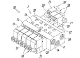
- the manifold valve 1A of the first embodiment is a single solenoid type in which all the valve mechanisms 3A are provided with one pilot valve 21, but like the manifold valve 1B of the second embodiment shown in FIG.
- the single solenoid type valve mechanism 3A and the double solenoid type valve mechanism 3B having two pilot valves 21 may be incorporated in the manifold 2 in a mixed form, or all the valve mechanisms may be It may be a double solenoid type.
- the double solenoid type valve mechanism 3B has pilot valves 21 attached to both lateral sides of the manifold 2 via adapter plates 20, respectively.
- the adapter plate 20 and the pilot valve 21 attached to the side surface of the first and the adapter plates 20 and the pilot valve 21 attached to the other side surface have the same configuration.
- the configuration of the manifold 2 and the spool 15 is substantially the same as that of the first embodiment of FIG. 4, and therefore, the same reference numerals as those of FIG. The description is omitted.
- the double solenoid type valve mechanism 3A is configured to switch the spool 15 by alternately controlling the two pilot valves 21 on and off.
- the double solenoid type valve mechanism 3B ′ incorporated at the upper left of the manifold 2 is a three-position valve having a spool having three switching positions.
- the valve mechanism 3B ′ when the two pilot valves 21 are both off, the spool is returned to the neutral position by a return spring (not shown) provided in the adapter plate 20 ′ of one pilot valve 21. It is formed. Since the configuration of such a three-position valve is known, the description thereof is omitted here.
- the valve mechanisms 3A and 3B other than the valve mechanism 3B ′ are two-position valves whose spools have two switching positions.
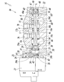
- FIGS. 12 and 13 show a third embodiment of a manifold valve according to the present invention.
- the manifold valve 1C of the third embodiment has a fluid supply hole 4 in the manifold 2 and two fluid discharges.
- the holes 5A and 5B are formed so as to occupy higher positions in the vertical direction. Accordingly, in the manifold valve 1C, the long hole portion 4b of the fluid supply hole 4 intersects the valve hole 6 from above the valve hole 6, and the long hole portion 5b of the two fluid discharge holes 5A and 5B is The pilot hole 8a, 8b intersects with the valve hole 6 from the lower side of the valve hole 6 and is formed at a position higher than the valve hole 6 inside the manifold 2. Since the configuration of the third embodiment other than the above is substantially the same as that of the first embodiment, the same reference numerals as those of the first embodiment are given to portions corresponding to the first embodiment. The description is omitted.
- the valve mechanism is a 5-port valve, but the valve mechanism may be a 4-port valve or a 3-port valve.
- the valve mechanism is a 4-port valve, the two fluid discharge holes 5A and 5B are communicated with each other inside the manifold 2, and both ends of the one fluid discharge holes 5A and 5B are closed with plugs. Only the other fluid discharge holes 5A, 5B are used.
- the valve mechanisms 3A and 3B are three-port valves, the fluid discharge hole and the output port are each one.
Abstract
Description
このため、できあがったマニホールドバルブは、別々に形成したマニホールドとバルブとを連結したことによって全体がかなり大形になっており、これに前記ガスケット及びボルトが加わることによってその重量も大きい。 In the case where a plurality of valves for controlling the pressure fluid are used in a collective state, conventionally, as disclosed in Patent Document 1, the required number is provided in a single-type manifold configured to be able to mount a plurality of valves. By installing this valve, it was used as a multiple manifold valve. At this time, the valves are individually fixed to the manifold with bolts via gaskets.
For this reason, the completed manifold valve is considerably enlarged as a whole by connecting the manifold and the valve formed separately, and the weight of the manifold valve is increased by adding the gasket and the bolt.
ところが、前述したように、従来のマニホールドバルブは、かなり大形で重量も大きいため、広い設置スペースを必要とするばかりでなく、前記可動部分に及ぼす機械的負担やエネルギー的負担が大きいという問題があった。このため、前記可動部分に及ぼす機械的負担の軽減や省エネルギーといった観点から、できるだけ小形化かつ軽量化されたマニホールドバルブの出現が望まれている。 In recent years, a plurality of valves are often mounted in a collective state on a movable part such as an industrial robot or an article conveying device. In such a case, the manifold valve is used.
However, as described above, the conventional manifold valve is quite large and heavy, so that not only a large installation space is required, but also the mechanical and energy burdens on the movable part are large. there were. For this reason, the appearance of a manifold valve that is as small and light as possible is desired from the viewpoint of reducing the mechanical burden on the movable part and saving energy.
前記流体供給孔及び流体排出孔の前記長孔部分が各弁孔と交叉する部分の上下方向長さは、前記弁孔の内径より小さく、前記流体供給孔及び流体排出孔の前記長孔部分が各弁孔と交叉する位置には、該弁孔の内径より大径化された円弧状の凹部が、該弁孔と同心状に形成される。 In the present invention, the fluid supply hole and the fluid discharge hole are formed at different positions in the vertical direction of the manifold, have a noncircular cross-sectional shape, and have a constant hole width in a part of the cross section. An elongated hole portion, and the elongated hole portion of the fluid supply hole and the elongated hole portion of the fluid discharge hole extend in opposite directions toward the vertical direction of the manifold, and It is desirable to cross each other from the upside down direction.
The vertical length of the portion where the elongated hole portion of the fluid supply hole and the fluid discharge hole intersects each valve hole is smaller than the inner diameter of the valve hole, and the elongated hole portion of the fluid supply hole and the fluid discharge hole is An arc-shaped recess having a diameter larger than the inner diameter of the valve hole is formed concentrically with the valve hole at a position intersecting with each valve hole.
このうち、前記流体供給孔4の主孔部分4aは、仮想円柱面C1の一部である円弧状壁11aと、該円弧状壁11aの両端から半径方向に延びる2つの側壁11bとで囲まれた部分であり、また、前記長孔部分4bは、前記仮想円柱面C1の一部である円弧状壁11cと、2つの互いに平行な側壁11dとで囲まれた、一定の孔幅W4を有する細長い長孔状をした部分である。前記円弧状壁11aと円弧状壁11cとは、前記仮想円柱面C1の直径方向の互いに反対側に位置する部分であり、従って、前記主孔部分4aと長孔部分4bとは、前記仮想円柱面C1の直径方向に真っ直ぐ連なっており、前記長孔部分4bの孔幅W4は、前記主孔部分4aの最大孔幅より狭い。 The
Among these, the
前記マニホールド2には、複数の前記弁孔6が、該マニホールド2の内部を横方向に真っ直ぐ貫通するように形成されている。該複数の弁孔6は、前記マニホールド2の上下方向の互いに同じ位置に、一定間隔を保って相互に平行に配置され、前記流体供給孔4及び流体排出孔5A,5Bの長孔部分4b,5bと直接交叉することにより、前記流体供給孔4及び流体排出孔5A,5Bにそれぞれ連通している。前記流体供給孔4の長孔部分4bと前記流体排出孔5A,5Bの長孔部分5bとは、前記弁孔6に互いに逆方向から交わっている。即ち、前記流体供給孔4の長孔部分4bは、前記弁孔6に該弁孔6の下方側から交わり、前記流体排出孔5A,5Bの長孔部分5bは、前記弁孔6に該弁孔6の上方側から交わっている。前記流体供給孔4の長孔部分4bが各弁孔6と交叉する部分の上下方向長さH4、及び、前記流体排出孔5A,5Bの長孔部分5bが各弁孔6と交叉する部分の上下方向長さH5は、何れも前記弁孔6の内径Dより小さく、このため、前記長孔部分4b,5bが各弁孔6と交わる位置には、該弁孔6の内径より大径化された円弧状の凹部14が、該弁孔6と同心状に形成されている。 Next, the
A plurality of the valve holes 6 are formed in the
さらに、前記弁孔6を、前記流体供給孔4及び流体排出孔5A,5Bの長孔部分4b,5bを横切るように形成することにより、図4及び図5に示すように該弁孔6内に挿入したスプール15の切換動作時に、各シール部材16a-16dが乗り上げる弁座17の側縁17aを、前記弁孔6の中心軸線Lと直交する平面上に形成することができる。 In this manner, the
Further, the
前記出力ポート7A,7Bは、前記マニホールド2の下面に形成しても良く、上面と下面の両方に形成しても良い。該出力ポート7A,7Bを上面と下面の両面に形成した場合には、何れか一方の面の出力ポート7A,7Bが選択的に使用され、他方の面の出力ポート7A,7Bはプラグ等で塞がれる。 On the upper surface of the
The
前記配管接続口9a,9bの内径は、前記仮想円柱面C1,C2の直径と同径か、又はそれより大径である。 In addition, the
The inner diameters of the
また、前記駆動用ピストン24と前記スプール15の端面との間の空間部38は、不図示の通孔を通じて大気に開放されている。 The driving
A
この状態から前記操作子41を押し下げると、前記Oリング43が前記パイロット連通孔33を通り越して下方に移動するため、前記操作子孔34の下半部34bと上半部34aとが互いに連通し、前記パイロット供給孔8aからのパイロット流体が、前記操作子孔34を通じてパイロット連通孔33から前記駆動用圧力室32に直接流入し、前記駆動用ピストン24が動作する。 The
When the operating
また、前記復帰用ピストン40と前記スプール15の端面との間の空間部50は、不図示の通孔を通じて大気に開放されている。 In the
The
図11において、マニホールド2及びスプール15の構成は、図4の第1実施形態の場合と実質的に同じであるから、両者の主要な同一構成部分に図4の場合と同様の符号を付し、その説明は省略する。
前記ダブルソレノイドタイプのバルブ機構3Aは、2つのパイロット弁21を交互にオン、オフ制御することにより、スプール15を切り換えるものである。 As shown in FIG. 11, the double solenoid
11, the configuration of the
The double solenoid
前記バルブ機構3B’以外のバルブ機構3A及び3Bは、スプールが2つの切換位置を持つ2位置弁である。 In FIG. 10, the double solenoid
The
従って、このマニホールドバルブ1Cにおいて、前記流体供給孔4の長孔部分4bは、前記弁孔6に該弁孔6の上方側から交わり、前記2つの流体排出孔5A,5Bの長孔部分5bは、前記弁孔6に該弁孔6の下方側から交わり、パイロット供給孔8a,8bは、前記マニホールド2の内部の、前記弁孔6より高い位置に形成されている。
なお、この第3実施形態の前記以外の構成は実質的に前記第1実施形態と同様であるから、該第1実施形態と対応する部分に該第1実施形態と同様の符号を付してその説明は省略する。 FIGS. 12 and 13 show a third embodiment of a manifold valve according to the present invention. The
Accordingly, in the
Since the configuration of the third embodiment other than the above is substantially the same as that of the first embodiment, the same reference numerals as those of the first embodiment are given to portions corresponding to the first embodiment. The description is omitted.
2 マニホールド
4 流体供給孔
4b 長孔部分
5A,5B 流体排出孔
5b 長孔部分
6 弁孔
7A,7B 出力ポート
14 凹部
15 スプール
20 アダプタプレート
21 パイロット弁
22 エンドプレート
24 駆動用ピストン
32 駆動用圧力室
40 復帰用ピストン
48 復帰用圧力室
X 縦方向
Y 横方向
Z 上下方向
W4,W5 孔幅
H4,H5 上下方向長さ
D 弁孔の内径 1A, 1B,
Claims (6)
- 流体供給孔及び流体排出孔が内部を貫通する押出材により形成され、前記流体供給孔及び流体排出孔の貫通方向である縦方向と、該縦方向に直交する横方向と、前記縦方向及び横方向の両方向に直交する上下方向とを有するマニホールド、
前記マニホールドの内部を横方向に貫通すると共に、前記流体供給孔及び流体排出孔の両方と直接交叉することによって該流体供給孔及び流体排出孔にそれぞれ連通する複数の弁孔、
前記マニホールドの上面及び下面のうちの少なくとも一方の面に、前記複数の弁孔に個別に連通するように形成された出力ポート、
前記弁孔の内部に摺動自在に挿入され、前記出力ポートと前記流体供給孔及び流体排出孔とを結ぶ流路を切り換えるスプール、
前記スプールを駆動するため、各弁孔の一端又は両端に個別に取り付けられた電磁式のパイロット弁、
を有することを特徴とする多連一体型マニホールドバルブ。
A fluid supply hole and a fluid discharge hole are formed of an extruded material penetrating through the inside, and a vertical direction which is a penetration direction of the fluid supply hole and the fluid discharge hole, a horizontal direction orthogonal to the vertical direction, the vertical direction and the horizontal direction A manifold having a vertical direction perpendicular to both directions,
A plurality of valve holes penetrating the inside of the manifold in the lateral direction and communicating with both the fluid supply hole and the fluid discharge hole by directly crossing both the fluid supply hole and the fluid discharge hole,
An output port formed on at least one of the upper and lower surfaces of the manifold so as to communicate with the plurality of valve holes individually;
A spool that is slidably inserted into the valve hole and switches a flow path connecting the output port and the fluid supply hole and fluid discharge hole;
In order to drive the spool, an electromagnetic pilot valve individually attached to one or both ends of each valve hole,
A manifold integrated manifold valve characterized by comprising:
- 前記流体供給孔と前記流体排出孔とは、前記マニホールドの上下方向の互いに異なる位置に形成されていて、断面形状が非円形であると共に、断面の一部に一定孔幅を有する長孔部分を有し、前記流体供給孔の長孔部分と前記流体排出孔の長孔部分とは、前記マニホールドの上下方向に向けて相互に逆向きに延在し、前記弁孔に対して互いに上下逆方向から交叉していることを特徴とする請求項1に記載のマニホールドバルブ。
The fluid supply hole and the fluid discharge hole are formed at different positions in the vertical direction of the manifold, have a non-circular cross-sectional shape, and a long hole portion having a constant hole width in a part of the cross section. The elongated hole portion of the fluid supply hole and the elongated hole portion of the fluid discharge hole extend in opposite directions toward the vertical direction of the manifold, and are opposite to each other with respect to the valve hole. The manifold valve according to claim 1, wherein the manifold valve is crossed.
- 前記流体供給孔及び流体排出孔の前記長孔部分が各弁孔と交叉する部分の上下方向長さは、前記弁孔の内径より小さいことを特徴とする請求項2に記載のマニホールドバルブ。
3. The manifold valve according to claim 2, wherein a length in a vertical direction of a portion where the elongated hole portion of the fluid supply hole and the fluid discharge hole intersects each valve hole is smaller than an inner diameter of the valve hole.
- 前記流体供給孔及び流体排出孔の前記長孔部分が各弁孔と交叉する位置には、該弁孔の内径より大径化された円弧状の凹部が、該弁孔と同心状に形成されていることを特徴とする請求項3に記載のマニホールドバルブ。
At the position where the elongated hole portion of the fluid supply hole and the fluid discharge hole intersects with each valve hole, an arcuate recess having a diameter larger than the inner diameter of the valve hole is formed concentrically with the valve hole. The manifold valve according to claim 3, wherein the manifold valve is provided.
- 前記パイロット弁は、アダプタプレートを介して前記マニホールドの側面に取り付けられ、前記アダプタプレートには、前記スプールの一端に当接する駆動用ピストンと、該駆動用ピストンにパイロット流体を作用させる駆動用圧力室とが設けられ、該駆動用圧力室は、前記パイロット弁を介して前記流体供給孔に接続されていることを特徴とする請求項1から4の何れかに記載のマニホールドバルブ。
The pilot valve is attached to a side surface of the manifold via an adapter plate. The adapter plate has a driving piston that abuts one end of the spool, and a driving pressure chamber that causes pilot fluid to act on the driving piston. The manifold valve according to any one of claims 1 to 4, wherein the drive pressure chamber is connected to the fluid supply hole via the pilot valve.
- 一端のみに前記パイロット弁が取り付けられた前記弁孔の他端には、エンドプレートが取り付けられ、該エンドプレートには、前記スプールの他端に当接する復帰用ピストンと、該復帰用ピストンにパイロット流体を作用させる復帰用圧力室とが設けられ、前記復帰用ピストンは、前記駆動用ピストンより小径をなし、前記復帰用圧力室は、前記流体供給孔に常時連通していることを特徴とする請求項5に記載のマニホールドバルブ。 An end plate is attached to the other end of the valve hole in which the pilot valve is attached to only one end. A return piston that contacts the other end of the spool, and a pilot to the return piston are attached to the end plate. A return pressure chamber for allowing fluid to act, wherein the return piston has a smaller diameter than the drive piston, and the return pressure chamber is always in communication with the fluid supply hole. The manifold valve according to claim 5.
Priority Applications (7)
| Application Number | Priority Date | Filing Date | Title |
|---|---|---|---|
| BR112017028158-9A BR112017028158A2 (en) | 2015-06-24 | 2016-06-20 | Multi- Unified manifold valve |
| RU2018102545A RU2708753C2 (en) | 2015-06-24 | 2016-06-20 | Integrated multi-valve header |
| DE112016002877.6T DE112016002877T5 (en) | 2015-06-24 | 2016-06-20 | Integrated manifold valve manifold |
| MX2017016362A MX2017016362A (en) | 2015-06-24 | 2016-06-20 | Integrated multiple valve manifold. |
| CN201680036656.6A CN107709861B (en) | 2015-06-24 | 2016-06-20 | Multi-connected integrated manifold valve |
| KR1020177037380A KR102647039B1 (en) | 2015-06-24 | 2016-06-20 | Multi-wire integrated manifold valve |
| US15/735,221 US10823299B2 (en) | 2015-06-24 | 2016-06-20 | Integrated multiple valve manifold |
Applications Claiming Priority (2)
| Application Number | Priority Date | Filing Date | Title |
|---|---|---|---|
| JP2015126841A JP6467711B2 (en) | 2015-06-24 | 2015-06-24 | Multiple integrated manifold valve |
| JP2015-126841 | 2015-06-24 |
Publications (1)
| Publication Number | Publication Date |
|---|---|
| WO2016208521A1 true WO2016208521A1 (en) | 2016-12-29 |
Family
ID=57585678
Family Applications (1)
| Application Number | Title | Priority Date | Filing Date |
|---|---|---|---|
| PCT/JP2016/068197 WO2016208521A1 (en) | 2015-06-24 | 2016-06-20 | Integrated multiple valve manifold |
Country Status (10)
| Country | Link |
|---|---|
| US (1) | US10823299B2 (en) |
| JP (1) | JP6467711B2 (en) |
| KR (1) | KR102647039B1 (en) |
| CN (1) | CN107709861B (en) |
| BR (1) | BR112017028158A2 (en) |
| DE (1) | DE112016002877T5 (en) |
| MX (1) | MX2017016362A (en) |
| RU (1) | RU2708753C2 (en) |
| TW (1) | TWI708026B (en) |
| WO (1) | WO2016208521A1 (en) |
Cited By (2)
| Publication number | Priority date | Publication date | Assignee | Title |
|---|---|---|---|---|
| IT201700072532A1 (en) * | 2017-06-28 | 2018-12-28 | Metal Work Spa | CIRCUIT BREAKER SOLENOID VALVE FOR A SOLENOID VALVE SYSTEM AND SOLENOID VALVE SYSTEM INCLUDING SUCH THE SECTIONING SOLENOID VALVE. |
| EP3822523A4 (en) * | 2018-09-07 | 2022-04-27 | SMC Corporation | Spool valve |
Families Citing this family (15)
| Publication number | Priority date | Publication date | Assignee | Title |
|---|---|---|---|---|
| US10613553B2 (en) * | 2013-07-09 | 2020-04-07 | Deka Products Limited Partnership | Modular valve apparatus and system |
| TWI650500B (en) * | 2018-04-02 | 2019-02-11 | 奇鼎科技股份有限公司 | Multi-channel valve block |
| JP1653727S (en) | 2018-11-22 | 2020-02-25 | ||
| CN109323018A (en) * | 2018-12-13 | 2019-02-12 | 李海源 | A kind of by-pass valve |
| JP1659524S (en) * | 2019-06-14 | 2020-05-18 | ||
| JP1659421S (en) * | 2019-09-03 | 2020-05-18 | ||
| JP1659525S (en) * | 2019-09-03 | 2020-05-18 | ||
| JP7439423B2 (en) * | 2019-09-09 | 2024-02-28 | Smc株式会社 | servo valve |
| JP7382205B2 (en) * | 2019-10-28 | 2023-11-16 | 川崎重工業株式会社 | Multi control valve unit |
| JP7023268B2 (en) * | 2019-12-06 | 2022-02-21 | 川崎重工業株式会社 | Multi-control valve device |
| RU197362U1 (en) * | 2019-12-09 | 2020-04-23 | Акционерное общество "Промышленная группа "Метран" (АО "ПГ "Метран") | INTEGRAL VALVE UNIT FOR CONNECTING KOPLANAR TYPE SENSORS TO WORKING LINE |
| JP1720711S (en) * | 2020-07-29 | 2022-07-26 | solenoid valve | |
| JP1722617S (en) * | 2020-11-13 | 2022-08-17 | Electromagnetically driven pilot valve | |
| DE102021208493A1 (en) | 2021-08-05 | 2023-02-09 | Festo Se & Co. Kg | multi-way valve |
| US20230184364A1 (en) * | 2021-12-15 | 2023-06-15 | Ford Global Technologies, Llc | Unitized valve body having annulus |
Citations (2)
| Publication number | Priority date | Publication date | Assignee | Title |
|---|---|---|---|---|
| JPH0522803U (en) * | 1991-09-06 | 1993-03-26 | 株式会社トキメツク | Manifold block |
| JPH09229226A (en) * | 1996-02-28 | 1997-09-05 | Ckd Corp | Solenoid valve manifold, and wiring cover for solenoid valve manifold |
Family Cites Families (35)
| Publication number | Priority date | Publication date | Assignee | Title |
|---|---|---|---|---|
| SU424999A1 (en) * | 1972-03-13 | 1974-04-25 | В. А. Койро , В. М. Резниченко | MULTI-GOLDEN SECTIONAL DISTRIBUTIONS Ptb ^ (^ • It- ^ O ^ - ^^ hT ^ -YZ! FshD ^^. V.ui- -1- * |
| DE2244493A1 (en) * | 1972-09-11 | 1974-04-04 | Bosch Gmbh Robert | DIRECTIONAL VALVE |
| US3771565A (en) * | 1972-11-06 | 1973-11-13 | Skinner Precision Ind Inc | Fluidic directional control valve assembly |
| US4406307A (en) * | 1981-03-31 | 1983-09-27 | Double A Products Company | Directional valve with spool transfer loop |
| JPH05203076A (en) * | 1991-05-27 | 1993-08-10 | Koganei:Kk | Manifold valve |
| DE4305608A1 (en) * | 1993-02-24 | 1994-08-25 | Bosch Gmbh Robert | Valve block |
| JP2804227B2 (en) | 1994-01-21 | 1998-09-24 | 株式会社コガネイ | Manifold solenoid valve |
| EP0704647B1 (en) * | 1994-04-18 | 2001-08-16 | SMC Kabushiki Kaisha | Combination of output piping connecting device and valve |
| DE4413657C1 (en) * | 1994-04-20 | 1995-11-02 | Festo Kg | Valve arrangement |
| JP3437265B2 (en) * | 1994-06-17 | 2003-08-18 | Smc株式会社 | Power supply device for pilot solenoid valve |
| JP3486238B2 (en) * | 1994-09-21 | 2004-01-13 | Smc株式会社 | Switching valve |
| DE4444024A1 (en) * | 1994-12-10 | 1996-06-13 | Festo Kg | Control device, in particular for controlling valves |
| SE503750C2 (en) * | 1995-05-15 | 1996-08-19 | Nordwin Ab | Hydraulic directional valve |
| JPH0942525A (en) * | 1995-07-26 | 1997-02-14 | Smc Corp | Pilot type change-over valve |
| JP3616475B2 (en) | 1997-05-23 | 2005-02-02 | 株式会社クボタ | Valve system |
| JP4045366B2 (en) * | 1997-08-11 | 2008-02-13 | Smc株式会社 | Piping joint for fluid pressure equipment |
| JP4016151B2 (en) * | 1997-08-14 | 2007-12-05 | Smc株式会社 | 2-port solenoid valve using 5-port solenoid valve body |
| JP4072738B2 (en) * | 1997-08-21 | 2008-04-09 | Smc株式会社 | 3 port solenoid valve using 5 port solenoid valve body |
| JP3941025B2 (en) * | 1998-01-06 | 2007-07-04 | Smc株式会社 | Rail mounted fluid pressure equipment |
| JP2000074246A (en) * | 1998-08-27 | 2000-03-14 | Ckd Corp | Solenoid valve and solenoid valve manifold |
| JP3468454B2 (en) * | 1999-07-12 | 2003-11-17 | Smc株式会社 | Switching valve with position detection function |
| JP3590772B2 (en) * | 2001-01-16 | 2004-11-17 | Smc株式会社 | Solenoid valve with sensor |
| JP3816020B2 (en) * | 2002-04-30 | 2006-08-30 | Smc株式会社 | Interlock valve |
| JP4258812B2 (en) * | 2004-04-22 | 2009-04-30 | Smc株式会社 | Articulated solenoid valve |
| CN100497963C (en) * | 2005-06-20 | 2009-06-10 | Smc株式会社 | Manifold-type solenoid valve assembly |
| JP4919002B2 (en) * | 2005-06-20 | 2012-04-18 | Smc株式会社 | Manifold solenoid valve assembly |
| WO2009046433A2 (en) * | 2007-10-05 | 2009-04-09 | Hydra-Flex, Inc. | Chemical delivery system |
| US7827785B2 (en) * | 2007-12-03 | 2010-11-09 | Deere & Company | Hydraulic system with warm up circuit |
| CN102203476B (en) * | 2008-11-05 | 2014-11-12 | 诺格伦有限责任公司 | Modular valve assembly |
| DE102010005229A1 (en) * | 2010-01-21 | 2011-07-28 | Hydac Fluidtechnik GmbH, 66280 | valve device |
| US10371272B2 (en) * | 2010-10-04 | 2019-08-06 | The Subsea Company | Shuttle valve |
| JP5505843B2 (en) * | 2011-04-07 | 2014-05-28 | Smc株式会社 | Pilot operated 3-position switching valve |
| JP5991288B2 (en) * | 2013-08-28 | 2016-09-14 | Smc株式会社 | 5-port switching valve with residual pressure discharge valve |
| JP5938839B2 (en) * | 2014-02-10 | 2016-06-22 | Smc株式会社 | Solenoid pilot spool valve |
| JP6327418B2 (en) * | 2014-09-04 | 2018-05-23 | Smc株式会社 | Dual 4-port solenoid valve |
-
2015
- 2015-06-24 JP JP2015126841A patent/JP6467711B2/en active Active
-
2016
- 2016-06-16 TW TW105119003A patent/TWI708026B/en not_active IP Right Cessation
- 2016-06-20 CN CN201680036656.6A patent/CN107709861B/en active Active
- 2016-06-20 US US15/735,221 patent/US10823299B2/en active Active
- 2016-06-20 DE DE112016002877.6T patent/DE112016002877T5/en active Pending
- 2016-06-20 RU RU2018102545A patent/RU2708753C2/en active
- 2016-06-20 MX MX2017016362A patent/MX2017016362A/en unknown
- 2016-06-20 WO PCT/JP2016/068197 patent/WO2016208521A1/en active Application Filing
- 2016-06-20 KR KR1020177037380A patent/KR102647039B1/en active IP Right Grant
- 2016-06-20 BR BR112017028158-9A patent/BR112017028158A2/en not_active Application Discontinuation
Patent Citations (2)
| Publication number | Priority date | Publication date | Assignee | Title |
|---|---|---|---|---|
| JPH0522803U (en) * | 1991-09-06 | 1993-03-26 | 株式会社トキメツク | Manifold block |
| JPH09229226A (en) * | 1996-02-28 | 1997-09-05 | Ckd Corp | Solenoid valve manifold, and wiring cover for solenoid valve manifold |
Cited By (3)
| Publication number | Priority date | Publication date | Assignee | Title |
|---|---|---|---|---|
| IT201700072532A1 (en) * | 2017-06-28 | 2018-12-28 | Metal Work Spa | CIRCUIT BREAKER SOLENOID VALVE FOR A SOLENOID VALVE SYSTEM AND SOLENOID VALVE SYSTEM INCLUDING SUCH THE SECTIONING SOLENOID VALVE. |
| US10753502B2 (en) | 2017-06-28 | 2020-08-25 | Metal Work S.P.A. | Circuit shut-off solenoid valve for a solenoid valve system and solenoid valve system comprising said shut-off solenoid valve |
| EP3822523A4 (en) * | 2018-09-07 | 2022-04-27 | SMC Corporation | Spool valve |
Also Published As
| Publication number | Publication date |
|---|---|
| TWI708026B (en) | 2020-10-21 |
| JP2017009073A (en) | 2017-01-12 |
| MX2017016362A (en) | 2018-03-02 |
| CN107709861A (en) | 2018-02-16 |
| US10823299B2 (en) | 2020-11-03 |
| RU2708753C2 (en) | 2019-12-11 |
| BR112017028158A2 (en) | 2018-08-28 |
| RU2018102545A (en) | 2019-07-25 |
| RU2018102545A3 (en) | 2019-10-21 |
| KR102647039B1 (en) | 2024-03-14 |
| KR20180020176A (en) | 2018-02-27 |
| DE112016002877T5 (en) | 2018-03-08 |
| TW201713887A (en) | 2017-04-16 |
| US20180135766A1 (en) | 2018-05-17 |
| CN107709861B (en) | 2020-05-01 |
| JP6467711B2 (en) | 2019-02-13 |
Similar Documents
| Publication | Publication Date | Title |
|---|---|---|
| JP6467711B2 (en) | Multiple integrated manifold valve | |
| EP0703391B1 (en) | Rail-mounted aggregate valve | |
| TWI513899B (en) | Valve body for pumps | |
| KR101369216B1 (en) | Pilot-operated three-position switching valve | |
| KR20180055825A (en) | Spool valve | |
| US9062693B2 (en) | Fluid operated actuator | |
| KR100216973B1 (en) | Pilot type change-over valve | |
| JP6684480B2 (en) | Cylinder drive manifold device and cylinder drive device | |
| CN209943015U (en) | Booster pump | |
| JP2001263506A (en) | Multiway valve | |
| EP3374679B1 (en) | Multifunctional sanitary valve and method of operating such | |
| JP6345013B2 (en) | Pneumatic cylinder device | |
| CN113167298B (en) | Cylinder driving device and flow path unit | |
| JP5726552B2 (en) | 3-way selector valve | |
| US8602055B2 (en) | Hydraulic valve device | |
| JPWO2020049870A1 (en) | Spool valve | |
| CN107023690B (en) | Reversing valve and air conditioning system | |
| US9709180B2 (en) | Directional poppet valve | |
| JP6103930B2 (en) | Power head assembly | |
| JP2002524697A (en) | Pulse controlled pneumatic 4-port 2-position directional control valve | |
| JP2023174496A (en) | solenoid valve manifold | |
| JP2020045957A (en) | Four-way switching valve | |
| US20130139909A1 (en) | Hydraulic system | |
| CA2961795A1 (en) | Manifold for a directional control valve for a valve actuator |
Legal Events
| Date | Code | Title | Description |
|---|---|---|---|
| 121 | Ep: the epo has been informed by wipo that ep was designated in this application |
Ref document number: 16814291 Country of ref document: EP Kind code of ref document: A1 |
|
| WWE | Wipo information: entry into national phase |
Ref document number: 15735221 Country of ref document: US |
|
| WWE | Wipo information: entry into national phase |
Ref document number: MX/A/2017/016362 Country of ref document: MX |
|
| ENP | Entry into the national phase |
Ref document number: 20177037380 Country of ref document: KR Kind code of ref document: A |
|
| WWE | Wipo information: entry into national phase |
Ref document number: 112016002877 Country of ref document: DE |
|
| WWE | Wipo information: entry into national phase |
Ref document number: 2018102545 Country of ref document: RU |
|
| REG | Reference to national code |
Ref country code: BR Ref legal event code: B01A Ref document number: 112017028158 Country of ref document: BR |
|
| 122 | Ep: pct application non-entry in european phase |
Ref document number: 16814291 Country of ref document: EP Kind code of ref document: A1 |
|
| ENP | Entry into the national phase |
Ref document number: 112017028158 Country of ref document: BR Kind code of ref document: A2 Effective date: 20171226 |