CN107709861B - Multi-connected integrated manifold valve - Google Patents
Multi-connected integrated manifold valve Download PDFInfo
- Publication number
- CN107709861B CN107709861B CN201680036656.6A CN201680036656A CN107709861B CN 107709861 B CN107709861 B CN 107709861B CN 201680036656 A CN201680036656 A CN 201680036656A CN 107709861 B CN107709861 B CN 107709861B
- Authority
- CN
- China
- Prior art keywords
- valve
- hole
- manifold
- fluid
- fluid supply
- Prior art date
- Legal status (The legal status is an assumption and is not a legal conclusion. Google has not performed a legal analysis and makes no representation as to the accuracy of the status listed.)
- Active
Links
Images


Classifications
-
- F—MECHANICAL ENGINEERING; LIGHTING; HEATING; WEAPONS; BLASTING
- F16—ENGINEERING ELEMENTS AND UNITS; GENERAL MEASURES FOR PRODUCING AND MAINTAINING EFFECTIVE FUNCTIONING OF MACHINES OR INSTALLATIONS; THERMAL INSULATION IN GENERAL
- F16K—VALVES; TAPS; COCKS; ACTUATING-FLOATS; DEVICES FOR VENTING OR AERATING
- F16K11/00—Multiple-way valves, e.g. mixing valves; Pipe fittings incorporating such valves
- F16K11/10—Multiple-way valves, e.g. mixing valves; Pipe fittings incorporating such valves with two or more closure members not moving as a unit
- F16K11/20—Multiple-way valves, e.g. mixing valves; Pipe fittings incorporating such valves with two or more closure members not moving as a unit operated by separate actuating members
- F16K11/22—Multiple-way valves, e.g. mixing valves; Pipe fittings incorporating such valves with two or more closure members not moving as a unit operated by separate actuating members with an actuating member for each valve, e.g. interconnected to form multiple-way valves
-
- F—MECHANICAL ENGINEERING; LIGHTING; HEATING; WEAPONS; BLASTING
- F15—FLUID-PRESSURE ACTUATORS; HYDRAULICS OR PNEUMATICS IN GENERAL
- F15B—SYSTEMS ACTING BY MEANS OF FLUIDS IN GENERAL; FLUID-PRESSURE ACTUATORS, e.g. SERVOMOTORS; DETAILS OF FLUID-PRESSURE SYSTEMS, NOT OTHERWISE PROVIDED FOR
- F15B13/00—Details of servomotor systems ; Valves for servomotor systems
- F15B13/02—Fluid distribution or supply devices characterised by their adaptation to the control of servomotors
- F15B13/06—Fluid distribution or supply devices characterised by their adaptation to the control of servomotors for use with two or more servomotors
- F15B13/08—Assemblies of units, each for the control of a single servomotor only
- F15B13/0803—Modular units
- F15B13/0807—Manifolds
- F15B13/0814—Monoblock manifolds
-
- F—MECHANICAL ENGINEERING; LIGHTING; HEATING; WEAPONS; BLASTING
- F15—FLUID-PRESSURE ACTUATORS; HYDRAULICS OR PNEUMATICS IN GENERAL
- F15B—SYSTEMS ACTING BY MEANS OF FLUIDS IN GENERAL; FLUID-PRESSURE ACTUATORS, e.g. SERVOMOTORS; DETAILS OF FLUID-PRESSURE SYSTEMS, NOT OTHERWISE PROVIDED FOR
- F15B13/00—Details of servomotor systems ; Valves for servomotor systems
- F15B13/02—Fluid distribution or supply devices characterised by their adaptation to the control of servomotors
- F15B13/06—Fluid distribution or supply devices characterised by their adaptation to the control of servomotors for use with two or more servomotors
- F15B13/08—Assemblies of units, each for the control of a single servomotor only
- F15B13/0803—Modular units
- F15B13/0807—Manifolds
- F15B13/0817—Multiblock manifolds
-
- F—MECHANICAL ENGINEERING; LIGHTING; HEATING; WEAPONS; BLASTING
- F15—FLUID-PRESSURE ACTUATORS; HYDRAULICS OR PNEUMATICS IN GENERAL
- F15B—SYSTEMS ACTING BY MEANS OF FLUIDS IN GENERAL; FLUID-PRESSURE ACTUATORS, e.g. SERVOMOTORS; DETAILS OF FLUID-PRESSURE SYSTEMS, NOT OTHERWISE PROVIDED FOR
- F15B13/00—Details of servomotor systems ; Valves for servomotor systems
- F15B13/02—Fluid distribution or supply devices characterised by their adaptation to the control of servomotors
- F15B13/06—Fluid distribution or supply devices characterised by their adaptation to the control of servomotors for use with two or more servomotors
- F15B13/08—Assemblies of units, each for the control of a single servomotor only
- F15B13/0803—Modular units
- F15B13/0832—Modular valves
- F15B13/0842—Monoblock type valves, e.g. with multiple valve spools in a common housing
-
- F—MECHANICAL ENGINEERING; LIGHTING; HEATING; WEAPONS; BLASTING
- F15—FLUID-PRESSURE ACTUATORS; HYDRAULICS OR PNEUMATICS IN GENERAL
- F15B—SYSTEMS ACTING BY MEANS OF FLUIDS IN GENERAL; FLUID-PRESSURE ACTUATORS, e.g. SERVOMOTORS; DETAILS OF FLUID-PRESSURE SYSTEMS, NOT OTHERWISE PROVIDED FOR
- F15B13/00—Details of servomotor systems ; Valves for servomotor systems
- F15B13/02—Fluid distribution or supply devices characterised by their adaptation to the control of servomotors
- F15B13/06—Fluid distribution or supply devices characterised by their adaptation to the control of servomotors for use with two or more servomotors
- F15B13/08—Assemblies of units, each for the control of a single servomotor only
- F15B13/0803—Modular units
- F15B13/0871—Channels for fluid
-
- F—MECHANICAL ENGINEERING; LIGHTING; HEATING; WEAPONS; BLASTING
- F16—ENGINEERING ELEMENTS AND UNITS; GENERAL MEASURES FOR PRODUCING AND MAINTAINING EFFECTIVE FUNCTIONING OF MACHINES OR INSTALLATIONS; THERMAL INSULATION IN GENERAL
- F16K—VALVES; TAPS; COCKS; ACTUATING-FLOATS; DEVICES FOR VENTING OR AERATING
- F16K11/00—Multiple-way valves, e.g. mixing valves; Pipe fittings incorporating such valves
- F16K11/02—Multiple-way valves, e.g. mixing valves; Pipe fittings incorporating such valves with all movable sealing faces moving as one unit
- F16K11/06—Multiple-way valves, e.g. mixing valves; Pipe fittings incorporating such valves with all movable sealing faces moving as one unit comprising only sliding valves, i.e. sliding closure elements
- F16K11/065—Multiple-way valves, e.g. mixing valves; Pipe fittings incorporating such valves with all movable sealing faces moving as one unit comprising only sliding valves, i.e. sliding closure elements with linearly sliding closure members
- F16K11/07—Multiple-way valves, e.g. mixing valves; Pipe fittings incorporating such valves with all movable sealing faces moving as one unit comprising only sliding valves, i.e. sliding closure elements with linearly sliding closure members with cylindrical slides
-
- F—MECHANICAL ENGINEERING; LIGHTING; HEATING; WEAPONS; BLASTING
- F16—ENGINEERING ELEMENTS AND UNITS; GENERAL MEASURES FOR PRODUCING AND MAINTAINING EFFECTIVE FUNCTIONING OF MACHINES OR INSTALLATIONS; THERMAL INSULATION IN GENERAL
- F16K—VALVES; TAPS; COCKS; ACTUATING-FLOATS; DEVICES FOR VENTING OR AERATING
- F16K27/00—Construction of housing; Use of materials therefor
- F16K27/003—Housing formed from a plurality of the same valve elements
-
- F—MECHANICAL ENGINEERING; LIGHTING; HEATING; WEAPONS; BLASTING
- F16—ENGINEERING ELEMENTS AND UNITS; GENERAL MEASURES FOR PRODUCING AND MAINTAINING EFFECTIVE FUNCTIONING OF MACHINES OR INSTALLATIONS; THERMAL INSULATION IN GENERAL
- F16K—VALVES; TAPS; COCKS; ACTUATING-FLOATS; DEVICES FOR VENTING OR AERATING
- F16K27/00—Construction of housing; Use of materials therefor
- F16K27/04—Construction of housing; Use of materials therefor of sliding valves
- F16K27/041—Construction of housing; Use of materials therefor of sliding valves cylindrical slide valves
-
- F—MECHANICAL ENGINEERING; LIGHTING; HEATING; WEAPONS; BLASTING
- F16—ENGINEERING ELEMENTS AND UNITS; GENERAL MEASURES FOR PRODUCING AND MAINTAINING EFFECTIVE FUNCTIONING OF MACHINES OR INSTALLATIONS; THERMAL INSULATION IN GENERAL
- F16K—VALVES; TAPS; COCKS; ACTUATING-FLOATS; DEVICES FOR VENTING OR AERATING
- F16K27/00—Construction of housing; Use of materials therefor
- F16K27/04—Construction of housing; Use of materials therefor of sliding valves
- F16K27/048—Electromagnetically actuated valves
-
- F—MECHANICAL ENGINEERING; LIGHTING; HEATING; WEAPONS; BLASTING
- F16—ENGINEERING ELEMENTS AND UNITS; GENERAL MEASURES FOR PRODUCING AND MAINTAINING EFFECTIVE FUNCTIONING OF MACHINES OR INSTALLATIONS; THERMAL INSULATION IN GENERAL
- F16K—VALVES; TAPS; COCKS; ACTUATING-FLOATS; DEVICES FOR VENTING OR AERATING
- F16K3/00—Gate valves or sliding valves, i.e. cut-off apparatus with closing members having a sliding movement along the seat for opening and closing
- F16K3/30—Details
- F16K3/314—Forms or constructions of slides; Attachment of the slide to the spindle
-
- F—MECHANICAL ENGINEERING; LIGHTING; HEATING; WEAPONS; BLASTING
- F16—ENGINEERING ELEMENTS AND UNITS; GENERAL MEASURES FOR PRODUCING AND MAINTAINING EFFECTIVE FUNCTIONING OF MACHINES OR INSTALLATIONS; THERMAL INSULATION IN GENERAL
- F16K—VALVES; TAPS; COCKS; ACTUATING-FLOATS; DEVICES FOR VENTING OR AERATING
- F16K31/00—Actuating devices; Operating means; Releasing devices
- F16K31/12—Actuating devices; Operating means; Releasing devices actuated by fluid
- F16K31/122—Actuating devices; Operating means; Releasing devices actuated by fluid the fluid acting on a piston
Abstract
A plurality of valve mechanisms are integrally assembled to one manifold, so that a multi-unit manifold valve which is small and light is obtained. The manifold valve of multiple-unit type is provided with a manifold (2) formed by extrusion parts with a fluid supply hole (4) and fluid discharge holes (5A, 5B) penetrating through the interior thereof, wherein the manifold valve comprises: a plurality of valve holes (6) that directly intersect both the fluid supply hole (4) and the fluid discharge holes (5A, 5B) and communicate with the fluid supply hole (4) and the fluid discharge holes (5A, 5B), respectively; output ports (7A, 7B) formed to communicate with the valve holes (6), respectively; a spool valve (15) slidably inserted into the valve hole (6); and electromagnetic pilot valves (21) respectively mounted on one or both ends of each valve hole (6).
Description
Technical Field
The present invention relates to a multiple integrated manifold valve in which a plurality of valve mechanisms are integrally assembled to one manifold.
Background
When valves for controlling pressure fluid are used in a plurality of aggregated states, conventionally, as disclosed in patent document 1, a required number of valves are mounted on a single manifold configured to be able to mount a plurality of valves, and are used as multiple manifold valves. At this time, the valves are fixed to the manifolds by bolts via gaskets.
Therefore, the manifold valve manufactured is considerably large in size as a whole by connecting a manifold formed separately to the valve, and the gasket and the bolt are added thereto, so that the weight thereof is also large.
In recent years, in many cases, a plurality of valves are mounted in an assembled state on a movable portion of an industrial robot, an article transport device, or the like, and in such a case, the manifold valve is used.
However, as described above, the conventional manifold valve is relatively large in size and heavy in weight, and therefore has the following problems: not only a wide installation space is required, but also a mechanical load and an energy load are imposed on the movable portion. Therefore, from the viewpoint of reducing the mechanical load on the movable portion and saving energy, a manifold valve that is as small and light as possible is desired.
On the other hand, patent document 2 discloses a valve system in which a plurality of valve elements are assembled to one valve body. In this valve system, the valve element is mounted in a mounting hole formed in the valve body, and the valve system can be made smaller and lighter than the manifold valve disclosed in patent document 1.
However, in this valve system, the oil passage is formed between the valve body and the oil passage forming member by overlapping and fixing the oil passage forming member that is a separate body from the valve body on both surfaces of the valve body, and further, the cover is overlapped and fixed on the outer surface of one of the oil passage forming members, and the joint for connecting the pipe is formed on the cover.
Prior art documents
Patent document
Patent document 1: japanese laid-open patent publication No. 7-208627
Patent document 2: japanese laid-open patent publication No. 10-325483
Disclosure of Invention
Problems to be solved by the invention
The technical subject of the invention is to form a multiple integrated manifold valve which is more miniaturized and lighter than the prior product by integrally assembling a plurality of valve mechanisms on one manifold.
Means for solving the problems
In order to solve the above problem, the present invention provides a multiple integrated manifold valve, comprising: a manifold formed of an extruded member having a fluid supply hole and a fluid discharge hole penetrating therethrough, and having a longitudinal direction as a penetrating direction of the fluid supply hole and the fluid discharge hole, a lateral direction orthogonal to the longitudinal direction, and an up-down direction orthogonal to both the longitudinal direction and the lateral direction; a plurality of valve holes which penetrate the inside of the manifold in a lateral direction and communicate with the fluid supply hole and the fluid discharge hole by directly intersecting both the fluid supply hole and the fluid discharge hole; an output port formed on at least one of an upper surface and a lower surface of the manifold so as to communicate with the plurality of valve holes, respectively; a spool valve slidably inserted into the valve hole and switching a flow path connecting the output port to the fluid supply hole and the fluid discharge hole; and electromagnetic pilot valves respectively installed at one end or both ends of each valve hole in order to drive the slide valve.
In the present invention, it is preferable that the fluid supply hole and the fluid discharge hole are formed at mutually different positions in the up-down direction of the manifold, have a non-circular cross-sectional shape, and have a long hole portion having a constant hole width in a part of the cross-section, the long hole portion of the fluid supply hole and the long hole portion of the fluid discharge hole extending in opposite directions to each other toward the up-down direction of the manifold and intersecting the valve hole from the up-down opposite direction to each other.
The length in the vertical direction of the portion where the long hole portions of the fluid supply hole and the fluid discharge hole intersect each valve hole is smaller than the inner diameter of the valve hole, and an arc-shaped recess having a diameter larger than the inner diameter of the valve hole is formed concentrically with the valve hole at the position where the long hole portions of the fluid supply hole and the fluid discharge hole intersect each valve hole.
According to a specific configuration of the present invention, the pilot valve is attached to a side surface of the manifold via an adapter plate (adapter plate), the adapter plate is provided with a driving piston which abuts on one end of the spool valve, and a driving pressure chamber which causes a pilot fluid to act on the driving piston, and the driving pressure chamber is connected to the fluid supply hole via the pilot valve.
According to another specific configuration of the present invention, an end plate is attached to the other end of the valve hole to which the pilot valve is attached at only one end, and a recovery piston which is in contact with the other end of the spool and a recovery pressure chamber which causes pilot fluid to act on the recovery piston are provided in the end plate, the recovery piston having a smaller diameter than the driving piston, and the recovery pressure chamber is always in communication with the fluid supply hole.
Effects of the invention
According to the present invention, a manifold valve having a plurality of valve holes formed in one manifold through which a fluid supply hole and a fluid discharge hole pass is formed so as to directly intersect the fluid supply hole and the fluid discharge hole, a spool is inserted into each valve hole, and a pilot valve or the like for driving the spool is attached to the manifold, whereby a multiple integrated manifold valve having a further smaller size and a lighter weight than conventional products can be obtained.
Drawings
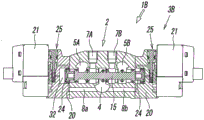
Fig. 1 is a perspective view illustrating a first embodiment of a multiple integrated manifold valve according to the present invention with a part of a valve mechanism exploded.
Figure 2 is a top view of the finished manifold valve of figure 1.
Fig. 3 is a front view of fig. 2.
Fig. 4 is a sectional view taken along line IV-IV of fig. 2.
Fig. 5 is a sectional view taken along line V-V of fig. 3.
Fig. 6 is a perspective view of the block prior to formation of the manifold.
Fig. 7 is a cross-sectional view of fig. 6.
Fig. 8 is a perspective view of a manifold formed by machining the block of fig. 6.
Fig. 9 is a cross-sectional view of fig. 8.
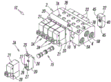
Fig. 10 is a perspective view illustrating a second embodiment of a multiple integrated manifold valve according to the present invention.
Fig. 11 is a cross-sectional view showing the manifold valve of fig. 10 cut away at the position of the valve mechanism in the center.
Fig. 12 is a perspective view illustrating a third embodiment of a multiple integrated manifold valve according to the present invention with a part of a valve mechanism exploded.
Fig. 13 is a sectional view showing the manifold valve of the third embodiment cut at the same position as fig. 4.
Detailed Description
Fig. 1 to 5 show a first embodiment of a multiple integrated manifold valve according to the present invention, and in a manifold valve 1A of the first embodiment, a plurality of valve mechanisms 3A for controlling a pressure fluid such as compressed air are integrally assembled to one manifold 2 formed as shown in fig. 8 and 9. The illustrated example is a five-way manifold valve in which five valve mechanisms 3A are assembled to the manifold 2, and all of the five valve mechanisms 3A are single solenoid type 5-port valves and have the same structure.
The manifold 2 is formed by performing necessary processing on a block 2 'as shown in fig. 6 and 7, and the block 2' is obtained by cutting an extruded metal (for example, aluminum alloy) material in a length required for assembling a required number of valve mechanisms 3A. The block 2 'is formed with a fluid supply hole 4 and fluid discharge holes 5A and 5B in advance, and as shown in fig. 8 and 9, the manifold 2 is formed by forming a plurality of valve holes 6, output ports 7A and 7B, pilot supply holes 8a and 8B, pipe connection ports 9a and 9B, screw holes 10, and the like in the block 2' in accordance with the number of valve mechanisms 3A to be assembled.
As shown in fig. 6, the block 2 'has a longitudinal direction (X direction) which is a pressing direction of the pressing member, a lateral direction (Y direction) which is orthogonal to the longitudinal direction, and a vertical direction (Z direction) which is orthogonal to both the longitudinal direction and the lateral direction, and one fluid supply hole 4 for supplying a pressure fluid to all the valve mechanisms 3A and two fluid discharge holes 5A, 5B for discharging a discharge fluid from all the valve mechanisms 3A to the outside are vertically penetrated through the inside of the block 2' in the longitudinal direction.
As can also be seen from fig. 7, the fluid supply hole 4 is disposed at the center of the block body 2' in the lateral direction, and the two fluid discharge holes 5A, 5B are disposed on both sides of the fluid supply hole 4. Further, the fluid supply hole 4 and the fluid discharge holes 5A, 5B are formed at different positions from each other in the vertical direction of the block body 2', the fluid supply hole 4 is formed at a position lower than the two fluid discharge holes 5A, 5B, and the two fluid discharge holes 5A, 5B are formed at the same position as each other.
The fluid supply hole 4 and the fluid discharge holes 5A and 5B are each a non-circular hole having a main hole portion 4a and 5A and an elongated hole portion 4B and 5B. The fluid discharge holes 5A and 5B have the same sectional shape as each other or are bilaterally symmetrical.
The main hole portion 4a of the fluid supply hole 4 is surrounded by an arc-shaped wall 11a which is a part of a virtual cylindrical surface C1 and two side walls 11b extending in the radial direction from both ends of the arc-shaped wall 11a, and the long hole portion 4b is a long and thin long hole-shaped portion formed to have a constant hole width W4 and surrounded by an arc-shaped wall 11C which is a part of the virtual cylindrical surface C1 and two side walls 11d parallel to each other. The arc-shaped wall 11a and the arc-shaped wall 11C are portions located on opposite sides of the imaginary cylindrical surface C1 in the diameter direction, and therefore, the main hole portion 4a and the long hole portion 4b are straightly connected in the diameter direction of the imaginary cylindrical surface C1, and the hole width W4 of the long hole portion 4b is smaller than the maximum hole width of the main hole portion 4 a.
On the other hand, the main hole portion 5A of the fluid discharge holes 5A and 5B is surrounded by the arc-shaped wall 12a which is a part of the virtual cylindrical surface C2 and the left and right side walls 12B connected to both ends of the arc-shaped wall 12a, and the elongated hole portion 5B is formed in an elongated hole shape having a constant hole width W5 and surrounded by the arc-shaped wall 12C which is a part of the virtual cylindrical surface C2 and the two side walls 12d parallel to each other. The main hole portion 5a and the long hole portion 5b are connected in the diameter direction of the imaginary cylindrical surface C2. The arc-shaped wall 12a and the arc-shaped wall 12C are located on opposite sides of the virtual cylindrical surface C2 in the radial direction.
The imaginary cylindrical surfaces C1 and C2 are the same diameter, the hole widths W5 of the long hole portions 5B of the two fluid discharge holes 5A, 5B are equal to each other, and the hole width W4 of the long hole portion 4B of the fluid supply hole 4 is formed to be equal to or smaller than the hole width W5 of the long hole portion 5B of the fluid discharge hole 5A, 5B.
Further, the long hole portion 4B of the fluid supply hole 4 and the long hole portion 5B of the fluid discharge holes 5A, 5B extend in the block body 2' in the vertical direction in the opposite direction to each other and in parallel. That is, the elongated hole portion 4B of the fluid supply hole 4 extends upward inside the block body 2 ', the elongated hole portions 5B of the fluid discharge holes 5A, 5B extend downward inside the block body 2 ', and the front end (upper end) of the elongated hole portion 4B of the fluid supply hole 4 and the front end (lower end) of the elongated hole portions 5B of the fluid discharge holes 5A, 5B occupy substantially the same position in the vertical direction of the block body 2 '.
Next, the manifold 2 obtained by machining the block 2' will be described with reference to fig. 8 and 9.
The manifold 2 is formed with a plurality of valve holes 6 extending straight through the manifold 2 in the lateral direction. The plurality of valve holes 6 are arranged in parallel with each other at the same position in the vertical direction of the manifold 2 with a constant interval therebetween, and directly intersect the long hole portions 4B and 5B of the fluid supply hole 4 and the fluid discharge holes 5A and 5B, thereby communicating with the fluid supply hole 4 and the fluid discharge holes 5A and 5B, respectively. The long hole portions 4B of the fluid supply hole 4 and the long hole portions 5B of the fluid discharge holes 5A, 5B intersect the valve hole 6 from opposite directions to each other. That is, the long hole portion 4B of the fluid supply hole 4 intersects the valve hole 6 from the lower side of the valve hole 6, and the long hole portions 5B of the fluid discharge holes 5A and 5B intersect the valve hole 6 from the upper side of the valve hole 6. Since the vertical length H4 of the portion where the long hole portion 4B of the fluid supply hole 4 intersects each valve hole 6 and the vertical length H5 of the portion where the long hole portion 5B of the fluid discharge hole 5A, 5B intersects each valve hole 6 are both smaller than the inner diameter D of the valve hole 6, an arc-shaped recess 14 having a diameter larger than the inner diameter of the valve hole 6 is formed concentrically with the valve hole 6 at the position where the long hole portions 4B, 5B intersect each valve hole 6.
By forming the valve hole 6 at a position directly intersecting the fluid supply hole 4 and the fluid discharge holes 5A and 5B in this manner, the valve hole 6 is formed at a position vertically separated from the fluid supply hole 4 and the fluid discharge holes 5A and 5B, and thus the height, i.e., the vertical width of the manifold 2 can be significantly reduced as compared with a case where the manifold is communicated with the flow path holes by communication holes, and the manifold valve 1A can be downsized. Further, compared to the case where a manifold formed separately is connected to a valve, the overall size can be significantly reduced, and a gasket, a connecting bolt, and the like are not required at all, so that a significant reduction in weight can be achieved.
Further, by forming the valve hole 6 as the elongated hole portions 4B, 5B crossing the fluid supply hole 4 and the fluid discharge holes 5A, 5B, it is possible to form the side edge 17a of the valve seat 17 on which the respective seal members 16a to 16d are seated on a plane orthogonal to the central axis L of the valve hole 6 when the switching operation of the spool valve 15 inserted into the valve hole 6 is performed as shown in fig. 4 and 5.
In the illustrated example, five valve holes 6 are provided, but the number of the valve holes 6 is not limited to five, and may be increased or decreased as appropriate according to the number of the valve mechanisms 3A to be assembled.
A plurality of the output ports 7A, 7B communicating with the plurality of valve holes 6, respectively, are provided on the upper surface of the manifold 2. In the illustrated example, two output ports 7A, 7B are provided for each valve hole 6 so as to be adjacent to each other in the lateral direction of the manifold 2 along the valve hole 6, one first output port 7A communicates with the valve hole 6 at a position between the fluid supply hole 4 and the first fluid discharge hole 5A, and the other second output port 7B communicates with the valve hole 6 at a position between the fluid supply hole 4 and the second fluid discharge hole 5B.
The output ports 7A and 7B may be formed on the lower surface of the manifold 2, or may be formed on both the upper surface and the lower surface. When the output ports 7A and 7B are formed on both the upper surface and the lower surface, the output ports 7A and 7B on either surface are selectively used, and the output ports 7A and 7B on the other surface are closed by a plunger or the like.
The pipe connection ports 9a and 9B are formed at both ends of the manifold 2 in the longitudinal direction concentrically with the imaginary cylindrical surfaces C1 and C2, and are connected to the pipe connection ports 9a and 9B by being screwed into joints connected to the ends of pipes, and the pipe connection ports 9a and 9B are formed by circular screw holes for connecting pipes to both ends of the fluid supply hole 4 and the fluid discharge holes 5A and 5B. When a pipe is not connected to the pipe connection port 9a or 9B on either end side of the fluid supply port 4 and the fluid discharge ports 5A and 5B, the pipe connection port 9a or 9B is closed by a plunger.
The inner diameters of the pipe connection ports 9a and 9b are equal to or larger than the diameters of the virtual cylindrical surfaces C1 and C2.
The pilot supply holes 8a and 8b extend in the lateral direction inside the manifold 2 from the fluid supply hole 4 as a starting point, wherein the tip of one first pilot supply hole 8a opens on one side surface of the manifold 2, and the tip of the other second pilot supply hole 8b opens on the other side surface of the manifold 2.
When the manifold valve 1A is formed using the manifold 2, as is apparent from fig. 1, 4, and 5, the spool valve 15 is slidably inserted into each of the valve holes 6, a pilot valve 21 is attached to one end side of each of the valve holes 6 via an adapter plate 20, and an end plate 22 is attached to the other end side of the valve hole 6.
The spool valve 15 has: a first seal member 16a that opens and closes a flow path connecting the fluid supply hole 4 and the first output port 7A; a second seal member 16B that opens and closes a flow path connecting the fluid supply hole 4 and the second output port 7B; a third seal member 16c for opening and closing a flow path connecting the first output port 7A and the first fluid discharge hole 5A; a fourth seal member 16d for opening and closing a flow path connecting the second output port 7B and the second fluid discharge hole 5B; a fifth seal member 16e which constantly closes both end portions of the valve hole 6; and a sixth seal member 16 f.
The adapter plate 20 is a block-shaped member formed to be elongated in the vertical direction of the manifold 2, has a driving piston 24 and a manual operation mechanism 25, and is fixed to the manifold 2 by a mounting screw 26 screwed into the screw hole 10 on the side surface of the manifold 2, and the pilot valve 21 is fixed to the outer surface of the adapter plate 20 by a mounting screw 28 screwed into a screw hole 27 of the adapter plate 20.
The drive piston 24 is slidably disposed in the piston chamber 30 of the adapter plate 20 in the direction of the axis L via a lip-shaped seal member 31 attached to the outer periphery of the drive piston 24, and a leg 24a formed on an end surface facing the spool valve 15 abuts on the end surface of the spool valve 15, and the back surface of the drive piston 24 faces a drive pressure chamber 32 formed in the piston chamber 30.
The driving pressure chamber 32 is connected to the first pilot supply hole 8a from the pilot communication hole 33 through a lower half portion 34b of the operation element hole 34 of the manual operation mechanism 25, the pilot output hole 35, the pilot valve 21, the pilot input hole 36, an upper half portion 34a of the operation element hole 34 of the manual operation mechanism 25, and a pilot relay hole 37.
A space 38 between the driving piston 24 and the end surface of the spool 15 is opened to the atmosphere through a through hole not shown.
The pilot valve 21 is a 3-port type solenoid valve, and when current is supplied to the pilot valve 21, the pilot input hole 36 and the pilot output hole 35 communicate with each other, so that the pilot fluid from the first pilot supply hole 8a flows into the driving pressure chamber 32 from the pilot communication hole 33, and the driving piston 24 moves rightward as shown in fig. 4, thereby switching the spool 15 to the first position. At this time, the fluid supply hole 4 communicates with the first output port 7A, the second output port 7B communicates with the second fluid discharge hole 5B, the second seal member 16B for blocking the flow path connecting the fluid supply hole 4 and the second output port 7B, and the third seal member 16c for blocking the flow path connecting the first output port 7A and the first fluid discharge hole 5A.
When the pilot valve 21 is released from the energization, the pilot fluid in the driving pressure chamber 32 is discharged through the pilot valve 21, and therefore the spool 15 and the driving piston 24 are pushed by the return piston 40 provided in the end plate 22, moved in the left direction of fig. 4, and occupy the return position. Details of this point will be described later.
The manual operation mechanism 25 is configured to be in the same state as that in the case of energization to the pilot valve 21 by manual operation of an operation element 41 during power failure, maintenance, or the like, and the operation element 41 is housed in the operation element hole 34 so as to be capable of being pushed down, is constantly biased upward in the drawing by the force of the return spring 42, and normally occupies an inoperative position not shown. At this time, the lower half portion 34b and the upper half portion 34a of the operator hole 34 are blocked by an O-ring 43 attached to the outer periphery of the operator 41.
When the operation element 41 is pushed down from this state, the O-ring 43 moves downward beyond the pilot communication hole 33, so that the lower half portion 34b and the upper half portion 34a of the operation element hole 34 communicate with each other, and the pilot fluid from the pilot supply hole 8a directly flows from the pilot communication hole 33 into the driving pressure chamber 32 through the operation element hole 34, thereby operating the driving piston 24.
On the other hand, the end plate 22 attached to the other end side of the valve hole 6 is a vertically long block-shaped member similarly to the adapter plate 20, and is fixed to the manifold 2 by screwing the attachment screws 45 to the screw holes in the side surface of the manifold 2 similarly to the adapter plate 20.
The restoring piston 40 is slidably disposed in a piston chamber 46 formed in the end plate 22 in the direction of the axis L via a lip-shaped seal member 47 attached to the outer periphery thereof, a leg portion 40a formed on an end surface facing the spool valve 15 abuts on the end surface of the spool valve 15, and a back surface of the restoring piston 40 abuts on a restoring pressure chamber 48 formed in the piston chamber 46. The recovery pressure chamber 48 is always in communication with the second pilot supply hole 8b of the manifold 2 through a pilot relay hole 49 formed in the end plate 22, and configured to always supply a pilot fluid from the fluid supply hole 4.
Further, a space 50 between the return piston 40 and the end surface of the spool 15 is opened to the atmosphere through a through hole not shown.
The return piston 40 has a smaller diameter than the drive piston 24. Therefore, when the pilot valve 21 is energized to supply the pilot fluid to the drive pressure chamber 32 and act on the drive piston 24, the spool 15 is moved to the switching position of fig. 4 by the difference in fluid pressure acting force based on the difference in pressure receiving area between the two pistons 24 and 40, and is held at that position. When the pilot valve 21 is in the non-energized state, the pilot fluid in the driving pressure chamber 32 is discharged to the outside through the pilot valve 21, and therefore the spool 15 is pushed leftward in fig. 4 by the biasing force of the return piston 40 and moved to the return position. This state is shown by the second valve mechanism 3A from below in fig. 5. At this time, the fluid supply hole 4 communicates with the second output port 7B, the first output port 7A communicates with the first fluid discharge hole 5A, and the first seal member 16a for blocking the flow path connecting the fluid supply hole 4 and the first output port 7A, and the fourth seal member 16d for blocking the flow path connecting the second output port 7B and the second fluid discharge hole 5B.
Therefore, the valve mechanisms 3A can switch the spool valve 15 between the first position and the return position by energizing or releasing the one pilot valve 21, thereby switching the communication state of the ports.
In the illustrated embodiment, the adapter plate 20 and the pilot valve 21 of all the valve mechanisms 3A are attached to one side surface of the manifold 2, and the end plate 22 of all the valve mechanisms 3A is attached to the other side surface thereof, but the adapter plate 20 and the pilot valve 21 may be disposed opposite to the valve mechanisms 3A and the other valve mechanisms 3A of which the end plate 22 is partially disposed. Therefore, since the adapter plate 20 and the end plate 22 can be attached to either of the left and right side surfaces of the manifold 2, the positional relationship among the valve hole 6, the pilot supply holes 8a and 8b, and the screw hole 10 in the manifold 2 is configured to be the same between the left side surface and the right side surface, and the arrangement of the attachment screw 26 and the pilot relay hole 37 in the adapter plate 20 and the arrangement of the attachment screw 45 and the pilot relay hole 49 in the end plate 22 are also configured to be the same.
Further, the manifold valve 1A of the first embodiment is a single solenoid type in which all the valve mechanisms 3A are provided with one pilot valve 21, but the valve mechanisms 3A of the single solenoid type and the valve mechanisms 3B of a double solenoid type in which two pilot valves 21 are provided may be incorporated in the manifold 2 so as to be mixed, as in the manifold valve 1B of the second embodiment shown in fig. 10, or all the valve mechanisms may be of a double solenoid type.
As shown in fig. 11, the double-solenoid type valve mechanism 3B has pilot valves 21 attached to both lateral side surfaces of the manifold 2 via adapter plates 20, and the adapter plate 20 and the pilot valve 21 attached to one side surface of the manifold 2 have the same configuration as the adapter plate 20 and the pilot valve 21 attached to the other side surface.
In fig. 11, the manifold 2 and the spool 15 have substantially the same configurations as those of the first embodiment of fig. 4, and therefore, the same reference numerals as those of fig. 4 are given to the same main components of both, and the description thereof is omitted.
The valve mechanism 3A of the double solenoid type switches the spool valve 15 by controlling the two pilot valves 21 to be alternately turned on and off.
In fig. 10, a valve mechanism 3B' of a double solenoid type mounted on the leftmost side of the manifold 2 is a 3-position valve in which a spool has three switching positions. The valve mechanism 3B 'is configured to return the spool valve to the neutral position by a return spring (not shown) provided inside the adapter plate 20' of one pilot valve 21 when both pilot valves 21 are off. Since the structure of such a 3-position valve is well known, the description thereof will be omitted.
The valve mechanisms 3A and 3B other than the valve mechanism 3B' are 2-position valves in which the spool has two switching positions.
Fig. 12 and 13 show a third embodiment of the manifold valve of the present invention, and the manifold valve 1C of the third embodiment forms the fluid supply hole 4 inside the manifold 2 such that the fluid supply hole 4 occupies a position higher in the vertical direction than the two fluid discharge holes 5A, 5B.
Therefore, in the manifold valve 1C, the long hole portion 4B of the fluid supply hole 4 intersects the valve hole 6 from the upper side of the valve hole 6, the long hole portions 5B of the two fluid discharge holes 5A and 5B intersect the valve hole 6 from the lower side of the valve hole 6, and the pilot supply holes 8a and 8B are formed in the manifold 2 at a position higher than the valve hole 6.
Note that the third embodiment is substantially the same as the first embodiment except for the above-described configuration, and therefore, the same reference numerals as those of the first embodiment are given to portions corresponding to the first embodiment, and the description thereof is omitted.
In each of the above embodiments, the valve mechanism is a 5-port valve, but the valve mechanism may be a 4-port valve or a 3-port valve. In the case where the valve mechanism is a 4-port valve, the two fluid discharge holes 5A, 5B communicate with each other inside the manifold 2, and both ends of one fluid discharge hole 5A, 5B are closed by a plunger, and only the other fluid discharge hole 5A, 5B is used. In the case where the valve mechanisms 3A and 3B are 3-port valves, the fluid discharge hole and the output port are respectively provided in one piece.
Description of the reference numerals
1A, 1B, 1C manifold valve
2 manifold
4 fluid supply hole
4b long hole part
5A, 5B fluid discharge orifice
5b slotted hole part
6 valve hole
7A, 7B output port
14 concave part
15 slide valve
20 adapter plate
21 guide valve
22 end plate
24 driving piston
32 pressure chamber for driving
40 piston for recovery
48 pressure chamber for recovery
X longitudinal direction
Y transverse direction
Z up-and-down direction
W4 and W5 hole widths
Length in vertical direction of H4, H5
D inner diameter of valve bore.
Claims (6)
1. A manifold valve of multiple integrated type, comprising:
a manifold formed of an extruded member having a fluid supply hole and a fluid discharge hole penetrating therethrough, and having a longitudinal direction as a penetrating direction of the fluid supply hole and the fluid discharge hole, a lateral direction orthogonal to the longitudinal direction, and an up-down direction orthogonal to both the longitudinal direction and the lateral direction;
a plurality of valve holes which penetrate the inside of the manifold in a lateral direction and communicate with the fluid supply hole and the fluid discharge hole by directly intersecting with both the fluid supply hole and the fluid discharge hole;
an output port formed on at least one of an upper surface and a lower surface of the manifold so as to communicate with the plurality of valve holes, respectively;
a spool valve slidably inserted into the valve hole and switching a flow path connecting the output port to the fluid supply hole and the fluid discharge hole; and
and electromagnetic pilot valves respectively installed at one or both ends of each valve hole for driving the slide valve.
2. A multiple integral manifold valve in accordance with claim 1,
the fluid supply hole and the fluid discharge hole are formed at mutually different positions in the up-down direction of the manifold, have a non-circular cross-sectional shape, and have a long hole portion having a constant hole width in a part of the cross-section, the long hole portion of the fluid supply hole and the long hole portion of the fluid discharge hole extending in opposite directions to each other toward the up-down direction of the manifold and crossing the valve hole from the up-down opposite directions to each other.
3. A multiple integral manifold valve in accordance with claim 2,
the vertical length of the portion of the fluid supply hole and the fluid discharge hole where the elongated hole portions intersect each valve hole is smaller than the inner diameter of the valve hole.
4. A multiple integral manifold valve in accordance with claim 3,
an arc-shaped recess having a diameter larger than the inner diameter of the valve hole is formed concentrically with the valve hole at a position where the elongated hole portions of the fluid supply hole and the fluid discharge hole intersect the valve holes.
5. A multiple integrated manifold valve in accordance with any one of claims 1 to 4,
the pilot valve is attached to a side surface of the manifold via an adapter plate, the adapter plate is provided with a driving piston which abuts on one end of the spool, and a driving pressure chamber which causes a pilot fluid to act on the driving piston, and the driving pressure chamber is connected to the fluid supply hole via the pilot valve.
6. A multiple integral manifold valve in accordance with claim 5,
an end plate is attached to the other end of the valve hole to which the pilot valve is attached at only one end, and a recovery piston that is in contact with the other end of the spool and a recovery pressure chamber that causes pilot fluid to act on the recovery piston are provided in the end plate.
Applications Claiming Priority (3)
| Application Number | Priority Date | Filing Date | Title |
|---|---|---|---|
| JP2015-126841 | 2015-06-24 | ||
| JP2015126841A JP6467711B2 (en) | 2015-06-24 | 2015-06-24 | Multiple integrated manifold valve |
| PCT/JP2016/068197 WO2016208521A1 (en) | 2015-06-24 | 2016-06-20 | Integrated multiple valve manifold |
Publications (2)
| Publication Number | Publication Date |
|---|---|
| CN107709861A CN107709861A (en) | 2018-02-16 |
| CN107709861B true CN107709861B (en) | 2020-05-01 |
Family
ID=57585678
Family Applications (1)
| Application Number | Title | Priority Date | Filing Date |
|---|---|---|---|
| CN201680036656.6A Active CN107709861B (en) | 2015-06-24 | 2016-06-20 | Multi-connected integrated manifold valve |
Country Status (10)
| Country | Link |
|---|---|
| US (1) | US10823299B2 (en) |
| JP (1) | JP6467711B2 (en) |
| KR (1) | KR102647039B1 (en) |
| CN (1) | CN107709861B (en) |
| BR (1) | BR112017028158A2 (en) |
| DE (1) | DE112016002877T5 (en) |
| MX (1) | MX2017016362A (en) |
| RU (1) | RU2708753C2 (en) |
| TW (1) | TWI708026B (en) |
| WO (1) | WO2016208521A1 (en) |
Families Citing this family (17)
| Publication number | Priority date | Publication date | Assignee | Title |
|---|---|---|---|---|
| US10613553B2 (en) * | 2013-07-09 | 2020-04-07 | Deka Products Limited Partnership | Modular valve apparatus and system |
| IT201700072532A1 (en) | 2017-06-28 | 2018-12-28 | Metal Work Spa | CIRCUIT BREAKER SOLENOID VALVE FOR A SOLENOID VALVE SYSTEM AND SOLENOID VALVE SYSTEM INCLUDING SUCH THE SECTIONING SOLENOID VALVE. |
| TWI650500B (en) * | 2018-04-02 | 2019-02-11 | 奇鼎科技股份有限公司 | Multi-channel valve block |
| EP3822523A4 (en) * | 2018-09-07 | 2022-04-27 | SMC Corporation | Spool valve |
| JP1653727S (en) | 2018-11-22 | 2020-02-25 | ||
| CN109323018A (en) * | 2018-12-13 | 2019-02-12 | 李海源 | A kind of by-pass valve |
| JP1659524S (en) * | 2019-06-14 | 2020-05-18 | ||
| JP1659421S (en) * | 2019-09-03 | 2020-05-18 | ||
| JP1659525S (en) * | 2019-09-03 | 2020-05-18 | ||
| JP7439423B2 (en) * | 2019-09-09 | 2024-02-28 | Smc株式会社 | servo valve |
| JP7382205B2 (en) * | 2019-10-28 | 2023-11-16 | 川崎重工業株式会社 | Multi control valve unit |
| JP7023268B2 (en) * | 2019-12-06 | 2022-02-21 | 川崎重工業株式会社 | Multi-control valve device |
| RU197362U1 (en) * | 2019-12-09 | 2020-04-23 | Акционерное общество "Промышленная группа "Метран" (АО "ПГ "Метран") | INTEGRAL VALVE UNIT FOR CONNECTING KOPLANAR TYPE SENSORS TO WORKING LINE |
| JP1720711S (en) * | 2020-07-29 | 2022-07-26 | solenoid valve | |
| JP1722617S (en) * | 2020-11-13 | 2022-08-17 | Electromagnetically driven pilot valve | |
| DE102021208493A1 (en) | 2021-08-05 | 2023-02-09 | Festo Se & Co. Kg | multi-way valve |
| US20230184364A1 (en) * | 2021-12-15 | 2023-06-15 | Ford Global Technologies, Llc | Unitized valve body having annulus |
Citations (2)
| Publication number | Priority date | Publication date | Assignee | Title |
|---|---|---|---|---|
| US5771918A (en) * | 1994-04-18 | 1998-06-30 | Smc Kabushiki Kaisha | Device for connecting output pipe to valve |
| CN1280261A (en) * | 1999-07-12 | 2001-01-17 | 速睦喜股份有限公司 | Change-over valve with position detection function |
Family Cites Families (35)
| Publication number | Priority date | Publication date | Assignee | Title |
|---|---|---|---|---|
| SU424999A1 (en) * | 1972-03-13 | 1974-04-25 | В. А. Койро , В. М. Резниченко | MULTI-GOLDEN SECTIONAL DISTRIBUTIONS Ptb ^ (^ • It- ^ O ^ - ^^ hT ^ -YZ! FshD ^^. V.ui- -1- * |
| DE2244493A1 (en) * | 1972-09-11 | 1974-04-04 | Bosch Gmbh Robert | DIRECTIONAL VALVE |
| US3771565A (en) * | 1972-11-06 | 1973-11-13 | Skinner Precision Ind Inc | Fluidic directional control valve assembly |
| US4406307A (en) * | 1981-03-31 | 1983-09-27 | Double A Products Company | Directional valve with spool transfer loop |
| JPH05203076A (en) * | 1991-05-27 | 1993-08-10 | Koganei:Kk | Manifold valve |
| JP2526823Y2 (en) * | 1991-09-06 | 1997-02-26 | 株式会社トキメック | Manifold block |
| DE4305608A1 (en) * | 1993-02-24 | 1994-08-25 | Bosch Gmbh Robert | Valve block |
| JP2804227B2 (en) | 1994-01-21 | 1998-09-24 | 株式会社コガネイ | Manifold solenoid valve |
| DE4413657C1 (en) * | 1994-04-20 | 1995-11-02 | Festo Kg | Valve arrangement |
| JP3437265B2 (en) * | 1994-06-17 | 2003-08-18 | Smc株式会社 | Power supply device for pilot solenoid valve |
| JP3486238B2 (en) * | 1994-09-21 | 2004-01-13 | Smc株式会社 | Switching valve |
| DE4444024A1 (en) * | 1994-12-10 | 1996-06-13 | Festo Kg | Control device, in particular for controlling valves |
| SE9501794L (en) * | 1995-05-15 | 1996-08-19 | Nordwin Ab | Hydraulic directional valve |
| JPH0942525A (en) * | 1995-07-26 | 1997-02-14 | Smc Corp | Pilot type change-over valve |
| JP2957940B2 (en) * | 1996-02-28 | 1999-10-06 | シーケーディ株式会社 | Solenoid valve manifold and wiring cover for solenoid valve manifold |
| JP3616475B2 (en) | 1997-05-23 | 2005-02-02 | 株式会社クボタ | Valve system |
| JP4045366B2 (en) * | 1997-08-11 | 2008-02-13 | Smc株式会社 | Piping joint for fluid pressure equipment |
| JP4016151B2 (en) * | 1997-08-14 | 2007-12-05 | Smc株式会社 | 2-port solenoid valve using 5-port solenoid valve body |
| JP4072738B2 (en) * | 1997-08-21 | 2008-04-09 | Smc株式会社 | 3 port solenoid valve using 5 port solenoid valve body |
| JP3941025B2 (en) * | 1998-01-06 | 2007-07-04 | Smc株式会社 | Rail mounted fluid pressure equipment |
| JP2000074246A (en) * | 1998-08-27 | 2000-03-14 | Ckd Corp | Solenoid valve and solenoid valve manifold |
| JP3590772B2 (en) * | 2001-01-16 | 2004-11-17 | Smc株式会社 | Solenoid valve with sensor |
| JP3816020B2 (en) * | 2002-04-30 | 2006-08-30 | Smc株式会社 | Interlock valve |
| JP4258812B2 (en) * | 2004-04-22 | 2009-04-30 | Smc株式会社 | Articulated solenoid valve |
| JP4919002B2 (en) * | 2005-06-20 | 2012-04-18 | Smc株式会社 | Manifold solenoid valve assembly |
| CN100497963C (en) * | 2005-06-20 | 2009-06-10 | Smc株式会社 | Manifold-type solenoid valve assembly |
| WO2009046433A2 (en) * | 2007-10-05 | 2009-04-09 | Hydra-Flex, Inc. | Chemical delivery system |
| US7827785B2 (en) * | 2007-12-03 | 2010-11-09 | Deere & Company | Hydraulic system with warm up circuit |
| US9194508B2 (en) * | 2008-11-05 | 2015-11-24 | Norgren Gmbh | Modular valve assembly |
| DE102010005229A1 (en) * | 2010-01-21 | 2011-07-28 | Hydac Fluidtechnik GmbH, 66280 | valve device |
| WO2012047777A2 (en) * | 2010-10-04 | 2012-04-12 | The Subsea Company | Shuttle valve |
| JP5505843B2 (en) * | 2011-04-07 | 2014-05-28 | Smc株式会社 | Pilot operated 3-position switching valve |
| JP5991288B2 (en) * | 2013-08-28 | 2016-09-14 | Smc株式会社 | 5-port switching valve with residual pressure discharge valve |
| JP5938839B2 (en) * | 2014-02-10 | 2016-06-22 | Smc株式会社 | Solenoid pilot spool valve |
| JP6327418B2 (en) * | 2014-09-04 | 2018-05-23 | Smc株式会社 | Dual 4-port solenoid valve |
-
2015
- 2015-06-24 JP JP2015126841A patent/JP6467711B2/en active Active
-
2016
- 2016-06-16 TW TW105119003A patent/TWI708026B/en not_active IP Right Cessation
- 2016-06-20 DE DE112016002877.6T patent/DE112016002877T5/en active Pending
- 2016-06-20 KR KR1020177037380A patent/KR102647039B1/en active IP Right Grant
- 2016-06-20 BR BR112017028158-9A patent/BR112017028158A2/en not_active Application Discontinuation
- 2016-06-20 CN CN201680036656.6A patent/CN107709861B/en active Active
- 2016-06-20 RU RU2018102545A patent/RU2708753C2/en active
- 2016-06-20 US US15/735,221 patent/US10823299B2/en active Active
- 2016-06-20 WO PCT/JP2016/068197 patent/WO2016208521A1/en active Application Filing
- 2016-06-20 MX MX2017016362A patent/MX2017016362A/en unknown
Patent Citations (2)
| Publication number | Priority date | Publication date | Assignee | Title |
|---|---|---|---|---|
| US5771918A (en) * | 1994-04-18 | 1998-06-30 | Smc Kabushiki Kaisha | Device for connecting output pipe to valve |
| CN1280261A (en) * | 1999-07-12 | 2001-01-17 | 速睦喜股份有限公司 | Change-over valve with position detection function |
Also Published As
| Publication number | Publication date |
|---|---|
| RU2018102545A3 (en) | 2019-10-21 |
| BR112017028158A2 (en) | 2018-08-28 |
| KR102647039B1 (en) | 2024-03-14 |
| KR20180020176A (en) | 2018-02-27 |
| US20180135766A1 (en) | 2018-05-17 |
| TWI708026B (en) | 2020-10-21 |
| JP6467711B2 (en) | 2019-02-13 |
| RU2708753C2 (en) | 2019-12-11 |
| DE112016002877T5 (en) | 2018-03-08 |
| WO2016208521A1 (en) | 2016-12-29 |
| US10823299B2 (en) | 2020-11-03 |
| RU2018102545A (en) | 2019-07-25 |
| TW201713887A (en) | 2017-04-16 |
| CN107709861A (en) | 2018-02-16 |
| MX2017016362A (en) | 2018-03-02 |
| JP2017009073A (en) | 2017-01-12 |
Similar Documents
| Publication | Publication Date | Title |
|---|---|---|
| CN107709861B (en) | Multi-connected integrated manifold valve | |
| EP0703391B1 (en) | Rail-mounted aggregate valve | |
| EP1048854B1 (en) | Servo-driving pilot-type solenoid valve | |
| KR102601408B1 (en) | spool valve | |
| EP2982890B1 (en) | Pilot type solenoid valve | |
| KR20170045228A (en) | Dual 4-port electromagnetic valve | |
| US5038671A (en) | Control valve | |
| KR102305303B1 (en) | pneumatic valve assembly | |
| EP3627018B1 (en) | Cylinder drive apparatus with a cylinder drive manifold device | |
| WO2012104485A1 (en) | Directional valve equipped with pressure control | |
| US8602055B2 (en) | Hydraulic valve device | |
| US7320272B2 (en) | Hydraulic system | |
| KR20200099466A (en) | Solenoid valve and working machine | |
| CN113167298B (en) | Cylinder driving device and flow path unit | |
| JP5726552B2 (en) | 3-way selector valve | |
| US4838308A (en) | Multipurpose control valve | |
| EP3205890B1 (en) | Piloted flow diverter valve | |
| CN217029464U (en) | Energy-saving multi-way valve | |
| US9709180B2 (en) | Directional poppet valve | |
| KR20180049042A (en) | Valve device | |
| JP2020045957A (en) | Four-way switching valve | |
| JP5657294B2 (en) | Multi-system switching valve | |
| KR20150014743A (en) | Automatic reciprocating motion control device for reciprocatable double acting booster | |
| DE19623446A1 (en) | Electropneumatically piloted directional valve |
Legal Events
| Date | Code | Title | Description |
|---|---|---|---|
| PB01 | Publication | ||
| PB01 | Publication | ||
| SE01 | Entry into force of request for substantive examination | ||
| SE01 | Entry into force of request for substantive examination | ||
| GR01 | Patent grant | ||
| GR01 | Patent grant |