WO2016208387A1 - 濾過フィルタ群及び濾過装置 - Google Patents
濾過フィルタ群及び濾過装置 Download PDFInfo
- Publication number
- WO2016208387A1 WO2016208387A1 PCT/JP2016/067001 JP2016067001W WO2016208387A1 WO 2016208387 A1 WO2016208387 A1 WO 2016208387A1 JP 2016067001 W JP2016067001 W JP 2016067001W WO 2016208387 A1 WO2016208387 A1 WO 2016208387A1
- Authority
- WO
- WIPO (PCT)
- Prior art keywords
- filter group
- filtration filter
- holding body
- filtration
- film
- Prior art date
- Legal status (The legal status is an assumption and is not a legal conclusion. Google has not performed a legal analysis and makes no representation as to the accuracy of the status listed.)
- Ceased
Links
Images






Classifications
-
- B—PERFORMING OPERATIONS; TRANSPORTING
- B01—PHYSICAL OR CHEMICAL PROCESSES OR APPARATUS IN GENERAL
- B01D—SEPARATION
- B01D29/00—Filters with filtering elements stationary during filtration, e.g. pressure or suction filters, not covered by groups B01D24/00 - B01D27/00; Filtering elements therefor
-
- B—PERFORMING OPERATIONS; TRANSPORTING
- B01—PHYSICAL OR CHEMICAL PROCESSES OR APPARATUS IN GENERAL
- B01D—SEPARATION
- B01D33/00—Filters with filtering elements which move during the filtering operation
- B01D33/04—Filters with filtering elements which move during the filtering operation with filtering bands or the like supported on cylinders which are impervious for filtering
-
- B—PERFORMING OPERATIONS; TRANSPORTING
- B01—PHYSICAL OR CHEMICAL PROCESSES OR APPARATUS IN GENERAL
- B01D—SEPARATION
- B01D63/00—Apparatus in general for separation processes using semi-permeable membranes
Definitions
- the present invention relates to a filtration filter group that filters a filtration object contained in a fluid, and a filtration device that uses the filtration filter group.
- Patent Document 1 International Publication No. 2015/019889
- Patent Document 1 International Publication No. 2015/019889
- Patent Document 1 discloses a filtration filter for filtering a biological substance contained in a liquid.
- the filtration filter is attached so that the outer peripheral portion is fitted between the lid member and the storage member so that a tensile force is applied from the central portion toward the outer peripheral portion.
- the biological material is filtered by passing a liquid containing the biological material through the filter.
- the filtration filter is clogged by the filtration of the filtration object such as a biological substance.
- the filter is clogged, it is necessary to replace the filter.
- the apparatus of Patent Document 1 has a structure in which the outer peripheral portion of the filtration filter is fitted between the lid member and the storage member, the replacement and replacement operation of the lid member and the storage member is performed in order to replace the filtration filter. I need it. Therefore, the apparatus of Patent Document 1 has a problem that the replacement of the filtration filter is complicated. In particular, when a biological material is filtered, it is required to prevent different types of contamination (contamination). For this reason, it is necessary to replace the filtration filter every time the biological material that is the filtration object is changed.
- An object of the present invention is to solve the above-described problems, and to provide a filter group and a filter device that can more easily replace the filter.
- the filtration filter group includes: A membrane part for filtering an object to be filtered contained in the fluid; While holding the film part, a holding body provided with a plurality of through holes for exposing the film part at a plurality of locations, Is provided.
- the filtration device includes: A filtration filter comprising: a membrane part for filtering an object to be filtered contained in a fluid; and a holding body that holds the membrane part and is provided with a plurality of through holes for exposing the membrane part at a plurality of locations.
- a fluid supply part for supplying a fluid to the film part exposed from at least one of the plurality of through holes;
- a transport device that transports at least one of the filtration filter group and the fluid supply unit so that the fluid from the fluid supply unit is supplied to the membrane unit; Is provided.
- the “filtration filter” is composed of a film part exposed from one through hole and a part of a holding body located around the film part.
- a plurality of “filtration filters” connected together and integrated are referred to as a “filtration filter group”.
- the filter can be replaced more easily.
- FIG. 2 is a cross-sectional view taken along line A1-A1 of FIG.
- FIG. 3 is a sectional view taken along line B1-B1 of FIG.
- FIG. 5 is a partially enlarged perspective view of FIG. 4.
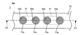
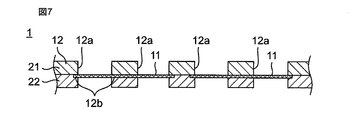
- FIG. 7 is a cross-sectional view taken along line C1-C1 of FIG. It is sectional drawing which shows the example which connected the holding body only to one main surface of a film
- the filtration filter group includes: A membrane part for filtering an object to be filtered contained in the fluid; While holding the film part, a holding body provided with a plurality of through holes for exposing the film part at a plurality of locations, Is provided.
- a plurality of the film portions may be provided so as to correspond to each of the plurality of through holes.
- one film part may be provided in one through hole. According to this configuration, the area where the film portion is provided can be reduced, so that the cost can be reduced.
- each of the plurality of film portions may be configured such that an outer peripheral portion thereof is held by the holding body. According to this configuration, the outer peripheral part of the film part can be firmly held by the holding body, and the center side of the film part can be exposed.
- the holding body may be connected to one main surface of the film part. According to this configuration, there is no need to provide a holding body on the other main surface of the film part, and the structure can be simplified and the cost can be reduced. Moreover, the flexibility of the holding body can be improved.
- the holding body may be connected to both one main surface and the other main surface of the film part. According to this configuration, when the filtration filter group is bent, the film portion can be prevented from being peeled off from the holding body.
- the film part may be configured to be held by the holding body. According to this structure, the position shift of the film part can be suppressed.
- the holding body may include a concave portion that fits with the outer peripheral portion of the film portion. According to this structure, the position shift of the film part can be suppressed.
- the holding body may be a tape-like member having flexibility, and the plurality of through holes may be provided along a longitudinal direction of the holding body.
- the filtration filter group can be wound and stored in a small size, or can be transformed into an arbitrary shape, so that convenience is improved.
- a cut line may be provided between the through holes adjacent to each other in the holding body. According to this configuration, a filter filter group having a desired length can be obtained by cutting along the cut line.
- a protective sheet may be provided on at least one main surface of the holding body to cover the film portions exposed at the plurality of locations. According to this configuration, it is possible to prevent dirt and damage to the filter group.
- a protective sheet may be provided on the outermost peripheral surface of the roll body obtained by winding the holding body in a roll shape. According to this configuration, not only the filtration filter group can be easily conveyed, but also the filtration filter group can be prevented from being soiled or damaged.
- a protective sheet may be provided on at least one of a pair of bottom surfaces facing each other of a roll body obtained by winding the holding body in a roll shape. According to this configuration, it is possible to prevent dirt and damage to the filter group.
- the membrane part may be a metal thin film having a plurality of through holes that separate biological substances from the fluid.
- the filtration device is A filtration filter comprising: a membrane part for filtering an object to be filtered contained in a fluid; and a holding body that holds the membrane part and is provided with a plurality of through holes for exposing the membrane part at a plurality of locations.
- a fluid supply part for supplying a fluid to the film part exposed from at least one of the plurality of through holes;
- a transport device that transports at least one of the filtration filter group and the fluid supply unit so that the fluid from the fluid supply unit is supplied to the membrane unit; Is provided.
- the transport device may transport at least one of the filtration filter group and the fluid supply unit such that a film unit to which the fluid supply unit supplies a fluid is sequentially changed.
- the filter can be easily replaced.
- the film portions are alternately positioned in a fluid supply region to which a fluid is supplied from the fluid supply portion and a removal region in which the filtered object to be filtered is removed from the film portion.
- the filtration filter group may be transported.
- the membrane part by moving the membrane part clogged with the filtered filtration object to the removal region and removing the filtration object, the membrane part can be reused and the cost can be reduced. it can.
- the filtration filter group is formed in an endless belt shape,
- the transport device may transport the filtration filter group clockwise or counterclockwise.
- the filter can be easily replaced by conveying the filter group in one direction clockwise or counterclockwise.
- the fluid supply unit includes a first cylinder and a second cylinder facing each other via the filtration filter group,
- the first cylinder and the second cylinder may be configured to be movable in a direction toward each other and in a direction away from each other.
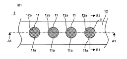
- FIG. 1 is a plan view showing a schematic configuration of a filtration filter group according to Embodiment 1 of the present invention.
- 2 is a cross-sectional view taken along line A1-A1 of FIG. 3 is a cross-sectional view taken along line B1-B1 of FIG.
- the filtration object is a biological substance contained in the liquid.
- the “biological substance” means a substance derived from a living organism such as a cell (eukaryotic organism), a bacterium (eubacteria), or a virus.
- cells eukaryotes
- examples of cells include eggs, sperm, induced pluripotent stem cells (iPS cells), ES cells, stem cells, mesenchymal stem cells, mononuclear cells, single cells, cell masses, suspension cells, and adhesions.
- sex cells nerve cells, leukocytes, lymphocytes, cells for regenerative medicine, autologous cells, cancer cells, circulating cancer cells (CTC), HL-60, HELA, and fungi.
- bacteria examples include gram positive bacteria, gram negative bacteria, Escherichia coli, and tuberculosis bacteria.
- virus examples include DNA virus, RNA virus, rotavirus, (bird) influenza virus, yellow fever virus, dengue fever virus, encephalitis virus, hemorrhagic fever virus, and immunodeficiency virus.
- the filtration filter group 1 includes a plurality of membrane portions 11 and a holding body 12 that holds the plurality of membrane portions 11.
- the film part 11 is composed of a circular metal thin film.
- the material of the film part 11 include gold, silver, copper, platinum, nickel, stainless steel, palladium, titanium, cobalt, and alloys thereof.
- the material of the film part 11 is more preferably a material that can be sterilized in various ways such as gamma irradiation, autoclave, and ethylene gas.
- the film part 11 may be a resin thin film, filter paper, or the like. That is, the film part 11 should just be a porous film.
- the dimensions of the film part 11 are, for example, a diameter of 8 mm and a thickness of 1.2 ⁇ m.
- it is 100 nm or more and 100 micrometers or less, and, as for the thickness of the film part 11, it is more preferable that it is 500 nm or more and 30 micrometers or less so that it may have moderate flexibility.
- the film part 11 has a pair of main surfaces facing each other, and has a plurality of through holes 11a penetrating both main surfaces.
- the through hole 11a separates a biological substance from the liquid.
- the shape and size of the through-hole 11a are appropriately set according to the shape and size of the biological material.
- the through holes 11a are, for example, arranged at regular intervals or periodically.
- the shape of the through hole 11a is, for example, a square when viewed from the main surface side of the film part 11.
- the size of the through hole 11a is, for example, from 0.1 ⁇ m to 500 ⁇ m in length and from 0.1 ⁇ m to 500 ⁇ m in width.
- the interval between the through holes 11a is, for example, greater than 1 time and less than 10 times, more preferably less than 3 times the opening diameter of the through holes 11a.
- membrane part 11 is 10% or more, for example.
- the holding body 12 is a tape-like member having flexibility.
- the holding body 12 is provided with a plurality of through holes 12a.
- the plurality of through holes 12a are provided at regular intervals along the longitudinal direction of the holding body 12, for example.
- the shape and size of the through hole 12a are appropriately set according to a desired amount of filtration processing, a filtration processing time, and the like.
- the shape of the through hole 12a is, for example, circular when viewed from the main surface side of the holding body 12.
- the size of the through hole 12a is, for example, 6 mm in diameter.
- the interval between the through holes 12a is, for example, 12 mm.
- Examples of the material of the holding body 12 include polypropylene, polyester, polyurethane, rayon, polyvinyl chloride, hydrogel, nylon, polyolefin, and paper.
- the material of the holder 12 is more preferably a material that can be sterilized in various ways, such as gamma irradiation, autoclaving, and ethylene gas. Examples of such a material include polyester, polyurethane, and polyvinyl chloride.
- the width of the holding body 12 is 12 mm, for example.
- the thickness of the holding body 12 is, for example, 500 ⁇ m.
- Each wall surface of the holding body 12 forming each through hole 12a is provided with a recess 12b.
- the recess 12b is formed in an annular shape, for example.
- the film portion 11 is held by the holding body 12 by fitting the outer peripheral portion into the recess 12b. Thereby, the film
- the holding body 12 has a two-layer structure, and includes a first layered member 21 and a second layered member 22.
- the first layered member 21 is connected to one main surface of the film part 11 by, for example, an adhesive.
- the second layered member 22 is connected to the other main surface of the film part 11 by, for example, an adhesive. That is, the holding body 12 is connected to both the one main surface and the other main surface of the film part 11.
- the 1st layered member 21 and the 2nd layered member 22 are mutually connected by the adhesive agent, for example.
- the said adhesive agent is a water-insoluble adhesive agent. Examples of such an adhesive include an epoxy adhesive and a silylated urethane resin adhesive.
- the recess 12 b is provided in at least one of the first layered member 21 and the second layered member 22.
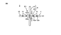
- FIG. 4 is a side view showing a schematic configuration of the filtration device.
- FIG. 5 is a partially enlarged perspective view of FIG.
- the filtration device 2 includes a transport device 3 and a fluid supply unit 4.
- the transport device 3 includes a filtration filter group such that the film portion 11 exposed from the specific through hole 12a is located in a fluid supply region E1 in which a first cylinder 41 and a second cylinder 42, which will be described later, face each other. 1 is transported. Moreover, the conveying apparatus 3 conveys the filtration filter group 1 so that the film
- the transport device 3 includes a supply reel 31 and a take-up reel 32.
- a filtration filter group 1 is wound around the supply reel 31.
- the supply reel 31 is provided with a feeding motor 31a.
- the filter group 1 is fed out from the supply reel 31 by driving the feeding motor 31a.
- the filter group 1 fed out from the supply reel 31 is taken up by the take-up reel 32.
- the take-up reel 32 is provided with a take-up motor 32a. For example, a constant tension is applied to the take-up reel 32 by driving the take-up motor 32a. Thereby, the filter group 1 fed out from the supply reel 31 is taken up by the take-up reel 32 simultaneously with the feeding out.
- the fluid supply unit 4 is a fluid supply region E1 located between the supply reel 31 and the take-up reel 32 so as to supply a liquid containing a biological substance to the film unit 11 exposed from the specific through hole 12a. Is provided.
- the fluid supply part 4 is provided with the 1st cylinder 41 and the 2nd cylinder 42, as shown in FIG.
- the fluid supply part 4 causes the first cylinder 41 and the second cylinder 42 to approach each other and to each other. It is comprised so that it may move to the direction which leaves
- the fluid supply part 4 is comprised so that the liquid containing a biological material may be supplied toward the inside of the 2nd cylinder 41 through the inside of the 1st cylinder 41, for example.
- the operation of the filtration device 2 is controlled based on a program stored in advance by a control unit (not shown) provided in the filtration device 2.
- the first cylinder 41 and the second cylinder 42 are moved in a direction in which the first cylinder 41 and the second cylinder 42 approach each other, and one opening end 41a of the first cylinder 41 and one opening end 42a of the second cylinder 42 are It contacts and communicates through the filter group 1.
- the opening end portions 41 a and 42 a are positioned so as to include the film portion 11 exposed from the specific through hole 12 a when viewed from the thickness direction of the filtration filter group 1.
- a liquid containing a biological substance is supplied so as to go to the inside of the second cylinder 42 through the inside of the first cylinder 41.
- membrane part 11 exposed from the specific through-hole 12a filters a biological material.
- the supply of the liquid containing the biological substance is continued for a certain time, for example, the time when the film part 11 is assumed to be clogged.
- first cylinder 41 and the second cylinder 42 are moved away from each other and retracted from the filter group 1.
- the membrane portion 11 to be filtered next (for example, the membrane portion exposed from the through hole adjacent to the specific through hole) is placed in the fluid supply region E1. Be transported.
- the fluid supply unit 4 supplies the liquid to the film unit 11 transported to the fluid supply region E1, and the transport device 3 replaces the film unit 11 located in the fluid supply region E1. Is called.
- the plurality of film portions 11 are held by one holding body 12. Thereby, even when the specific film
- the filtration apparatus 1 conveys the filtration filter group 1 so that the film
- a plurality of film portions 11 are provided so as to correspond to each of the plurality of through holes 12a.
- one film portion 11 is provided in one through hole 12a.
- the film part 11 is configured so that the outer peripheral part is held by the holding body 12, the outer peripheral part of the film part 11 is firmly held by the holding body, The center side of the film part 11 can be exposed.
- the membrane portion 11 is peeled from the holding body 12 when the filtration filter group 1 is bent. Can be suppressed.
- the film part 11 is configured to be sandwiched by the holding body 12, the positional deviation of the film part 11 can be suppressed.
- the holding body 12 since the holding body 12 includes the concave portion 12b that fits with the outer peripheral portion of the film portion 11, for example, the positional deviation of the film portion 11 can be suppressed.
- the holding body 12 is a flexible tape-like member
- the filtration filter group 1 can be wound and stored in a small size, or can be transformed into an arbitrary shape.
- the sex can be further improved.
- one film portion 11 is provided in one through hole 12a.
- the membrane portion 11 may be formed in a size including two or more through holes 12 a when viewed from the thickness direction of the filtration filter group 1. That is, one film portion 11 may be formed so as to be exposed from two or more through holes 12a.
- the holding body 12 is configured to be connected to both main surfaces of the film part 11, but the present invention is not limited to this.
- the holding body 12 may be connected only to one main surface of the film part 11 as shown in FIG. In this case, since it is not necessary to provide the second layered member 22 on the other main surface of the film part 11, the structure can be simplified and the cost can be reduced. Moreover, the flexibility of the holding body 12 can be improved.
- the filtering object is a biological material contained in the liquid, but the present invention is not limited to this.
- a large foreign substance contained in the liquid may be used as the filtering object.
- the filtering object may be a substance contained in a gas. That is, the filtration object may be a substance contained in the fluid, and may be, for example, PM2.5 contained in the air.
- the filtration filter group 1 and the filtration device 2 are used for filtering biological substances from a liquid, but the present invention is not limited to this.
- the filtration filter group 1 and the filtration device 2 may be used, for example, for concentrating components contained in a liquid.
- the fluid supply unit 4 is configured by a pair of cylinders of the first cylinder 41 and the second cylinder 42, but the present invention is not limited to this.
- the fluid supply unit 4 may be composed of a plurality of sets of cylinders, with the first cylinder 41 and the second cylinder 42 as a set. According to this configuration, a liquid containing a biological substance can be simultaneously filtered by the plurality of membrane parts 11, and it is possible to increase the amount of filtration processing and shorten the filtration time.
- the holding body 12 may be provided with a cutoff line 12c between the mutually adjacent through holes 12a and 12a. According to this configuration, it is possible to obtain the filtration filter group 1 having a desired length by cutting along the cutting line 12c. For example, it becomes possible to cut a part of the holding body 12 including the membrane part 11 obtained by filtering a biological material by a cutting line 12c and analyze it with a microscope or the like.
- the holding body 12 may be provided with a plurality of feed holes 13 as shown in FIG.
- the plurality of feed holes 13 may be provided at regular intervals along the longitudinal direction of the holding body 12, for example.
- the conveying apparatus 3 may be equipped with the wheel (not shown) provided with the some pin corresponding to the some feed hole 13 in this case, for example.
- the protective sheet 14 may be provided in the outermost peripheral surface of the roll body 5 which wound the holding body 12 (filtration filter group 1) in roll shape.
- a protective sheet (not shown) may be provided on at least one of the pair of bottom surfaces 5A and 5B facing each other of the roll body 5. According to this configuration, not only the filtration filter group can be easily conveyed, but also the filtration filter group can be prevented from being soiled or damaged.
- protective sheets 15 that cover the film portions 11 exposed at a plurality of locations may be provided on both main surfaces of the holding body 12. According to this configuration, it is possible to prevent dirt and damage to the filter group 1.
- the protective sheet 15 may be provided only on one main surface of the holding body 12 when the holding body 12 is wound in a roll shape, for example. According to this configuration, the flexibility of the holding body 12 can be improved.
- each protective sheet with the member which has flexibility, such as a polystyrene, polyethylene, polyester, a polyurethane, rayon, PVC, a hydrogel, nylon, polyolefin, a cellulose, for example.
- the material of each protective sheet is more preferably a material that can be sterilized in various ways, such as gamma irradiation, autoclave, and ethylene gas. Examples of such a material include polyester, polyurethane, and polyvinyl chloride.
- FIG. 12 is a plan view showing a schematic configuration of a filtration filter group according to Embodiment 2 of the present invention and a filtration device using the filtration filter group
- FIG. 13 is a sectional view taken along line D1-D1.
- the filtration filter group 1A according to the second embodiment is different from the filtration filter group 1 according to the first embodiment in that the holding body 12 is formed in a disc shape, and the plurality of film portions 11 are outer peripheral portions of the holding body 12. It is a point arranged along. In the second embodiment, the plurality of film portions 11 are arranged at equal intervals on a concentric circle with the center hole 12A of the holding body 12 as the center.
- the difference between the filtering device 2A according to the second embodiment and the filtering device 2 according to the first embodiment is that the conveying device 3 is configured to rotate the holding body 12.
- the transport device 3 includes a rotating body 33 that is inserted into the center hole 12 ⁇ / b> A of the holding body 12. As the rotator 33 rotates around the rotation axis R1 (for example, in the direction of the arrow in FIG. 12), the film unit 11 positioned in the fluid supply region E1 is sequentially changed.
- a plurality of film portions 11 are held by one holding body 12. Thereby, even when the specific film
- the plurality of film portions 11 are arranged at equal intervals on a circle centering on the center hole 12A of the holding body 12, but the present invention is not limited to this.
- the plurality of film portions 11 may be provided dispersed (for example, uniformly dispersed) over the entire holding body 12.
- the transport device 3 may be configured to sequentially change the film unit 11 located in the fluid supply region E1 by moving the holding body 12 in parallel.
- the conveying apparatus 3 may be configured to sequentially change the film unit 11 located in the fluid supply region E1 by moving the fluid supply unit 4.
- FIG. 15 is a perspective view showing a schematic configuration of a filtration device according to Embodiment 3 of the present invention.
- the difference between the filtration device 2B according to the third embodiment and the filtration device 2 according to the first embodiment is that the fluid supply unit 4 includes a rotating body 43.
- the filtration filter group 1 is disposed so as to be spirally wound around the outer peripheral surface of the rotating cylinder 43.
- the rotating cylinder 43 rotates around the rotation axis R2. Thereby, the filtration filter group 1 moves spirally along the outer peripheral surface of the rotating cylinder 43.
- through holes 43a are provided at positions facing the plurality of film portions 11 of the filter group 1 respectively.
- the liquid containing the biological substance is supplied in parallel or substantially parallel to the rotation axis R1 from one opening end 43b of the rotating cylinder 43 toward the other opening end 43c. In this process, a part of the liquid containing the biological substance passes through the membrane part 11 through the through hole 43a, and the membrane part 11 filters the biological substance.
- the liquid containing the biological substance is supplied in parallel or substantially in parallel to the film unit 11, the occurrence of clogging of the film unit 11 can be suppressed.
- FIG. 16 is a side view which shows schematic structure of the filtration apparatus which concerns on Embodiment 4 of this invention.
- the filtering device 2C according to the fourth embodiment is different from the filtering device 2 according to the first embodiment in that the transport device 3 is configured to transport the filter group 1 clockwise or counterclockwise.
- the filter filter group 1 is configured to pass through the liquid containing the derived substance.
- FIG. 16 shows an example in which the transport device 3 transports the filter group 1 clockwise.
- the transport device 3 includes four guide rollers 34 to 37 as shown in FIG.
- the filter group 1 is formed in an endless belt shape, and is looped around four guide rollers 34 to 37. At least one of the guide rollers 34 to 37 is provided with a rotation motor (not shown). When the rotary motor is driven, the guide rollers 34 to 37 are rotated, and the filtration filter group 1 is conveyed.
- a fluid supply region E1 for supplying a liquid 52 containing a biological substance 51 to each film portion 11 of the filtration filter group 1 is provided.
- a recess 44 is provided as a fluid supply part.
- a liquid 52 containing a biological substance 51 is stored in the recess 44.
- the biological substance 51 is filtered by each membrane portion 11 of the filtration filter group 1 as the filtration filter group 1 is conveyed along the recess 44 and passes through the liquid 52.
- a removal region E2 for removing the filtered biological material 51 from the film portion 11 is provided between the guide roller 36 and the guide roller 37.
- a blower (not shown) for blowing air to the filtration filter group 1 is provided in the removal region E2.
- the blower blows air from the surface opposite to the surface of the film part 11 to which the biological substance 51 is adhered, the biological substance 51 is removed from the film part 11.
- the removed biological material 51 is accumulated in the container 6.
- the membrane portion 11 from which the biological material 51 has been removed is transported to the fluid supply region E1 again by the filtration filter group 1 being transported by the rotation of the guide rollers 34 to 37, and the biological material 51 in the liquid 52 is removed. Filter. Thereafter, in the same manner, when the filter group 1 is conveyed by the rotation of the guide rollers 34 to 37, each membrane unit 11 is alternately conveyed to the fluid supply region E1 and the removal region E2, and the biological material 51 Filtration and removal are repeated alternately.
- the filtration filter can be easily replaced by transporting the filtration filter group 1 in one direction clockwise or counterclockwise.
- the membrane part 11 clogged with the filtered biological substance 51 is moved to the removal region E2 to remove the biological substance 51.
- the film part 11 can be reused and cost reduction can be aimed at.
- each membrane unit 11 is alternately conveyed to the fluid supply region E1 and the removal region E2 by conveying the filter group 1 in one direction clockwise or counterclockwise.
- the present invention is not limited to this. For example, after the filtration filter group 1 is transported in one direction and each membrane unit 11 is transported to the fluid supply region E1, the filtration filter group 1 is transported in the reverse direction and each membrane unit 11 is transported to the removal region E2. May be repeated.
- a sterilization process may be provided between the fluid supply area E1 and the removal area E2.
- the film portion 11 can be reused, but contamination by contamination can be reduced by providing a sterilization process.
- the biological material 51 is removed from the membrane portion 11 by blowing air onto the filtration filter group 1, but the present invention is not limited to this.
- the biological material 51 may be removed from the film part 11 using gravity.
- you may backwash using a liquid instead of spraying air.
- the filtration filter can be replaced more easily. Therefore, a filtration filter group that filters a filtration object contained in a fluid such as a biological substance or PM2.5, and a filtration device that uses the filtration filter group Useful for.
Landscapes
- Chemical & Material Sciences (AREA)
- Chemical Kinetics & Catalysis (AREA)
- Separation Using Semi-Permeable Membranes (AREA)
- Filtration Of Liquid (AREA)
Abstract
濾過フィルタの交換をより容易に行うことができる濾過フィルタ群を提供する。本発明に係る濾過フィルタ群(1)は、流体に含まれる濾過対象物を濾過する膜部(11)と、膜部(11)を保持するとともに、膜部(11)を複数箇所で露出させるための複数の貫通穴(12a)が設けられている保持体(12)と、を備える。
Description
本発明は、流体に含まれる濾過対象物を濾過する濾過フィルタ群、及び当該濾過フィルタ群を用いる濾過装置に関する。
従来、流体に含まれる濾過対象物を濾過する濾過フィルタとして、例えば、特許文献1(国際公開公報第2015/019889号)に開示されたものが知られている。
特許文献1には、液体に含まれる生物由来物質を濾過する濾過フィルタが開示されている。この濾過フィルタは、中央部から外周部に向かって引張力が掛かるように、外周部が蓋部材と収納部材との間に嵌合するように取り付けられる。この状態で、濾過フィルタに生物由来物質を含む液体を通過させることで、生物由来物質を濾過する。
濾過フィルタは、生物由来物質などの濾過対象物の濾過が進むことで、目詰まりを生じる。濾過フィルタが目詰まりすると、当該濾過フィルタを交換する必要がある。特許文献1の装置は、濾過フィルタの外周部を蓋部材と収納部材との間に嵌合させる構造であるため、濾過フィルタを交換するには、蓋部材と収納部材との取り外し及び取り付け動作が必要になる。従って、特許文献1の装置では、濾過フィルタの交換が煩雑であるという課題がある。また、特に、生物由来物質を濾過する際には、異種混合(コンタミネーション)を防止することが求められる。このため、濾過対象物となる生物由来物質を変更する度に、濾過フィルタを交換する必要がある。
本発明の目的は、前記課題を解決することにあって、濾過フィルタの交換をより容易に行うことができる濾過フィルタ群及び濾過装置を提供することにある。
前記目的を達成するために、本発明の一態様に係る濾過フィルタ群は、
流体に含まれる濾過対象物を濾過する膜部と、
前記膜部を保持するとともに、前記膜部を複数箇所で露出させるための複数の貫通穴が設けられている保持体と、
を備える。
流体に含まれる濾過対象物を濾過する膜部と、
前記膜部を保持するとともに、前記膜部を複数箇所で露出させるための複数の貫通穴が設けられている保持体と、
を備える。
また、本発明の一態様に係る濾過装置は、
流体に含まれる濾過対象物を濾過する膜部と、前記膜部を保持するとともに、前記膜部を複数箇所で露出させるための複数の貫通穴が設けられている保持体と、を備える濾過フィルタ群と、
前記複数の貫通穴のうちの少なくとも1つから露出する膜部に流体を供給する流体供給部と、
前記膜部に前記流体供給部からの流体が供給されるように前記濾過フィルタ群及び前記流体供給部の少なくとも一方を搬送する搬送装置と、
を備える。
流体に含まれる濾過対象物を濾過する膜部と、前記膜部を保持するとともに、前記膜部を複数箇所で露出させるための複数の貫通穴が設けられている保持体と、を備える濾過フィルタ群と、
前記複数の貫通穴のうちの少なくとも1つから露出する膜部に流体を供給する流体供給部と、
前記膜部に前記流体供給部からの流体が供給されるように前記濾過フィルタ群及び前記流体供給部の少なくとも一方を搬送する搬送装置と、
を備える。
なお、本明細書では、「濾過フィルタ」は、1つの貫通穴から露出する膜部と、その周囲に位置する保持体の一部とで構成されるものとする。また、この「濾過フィルタ」が複数連結され、一体化されたものを「濾過フィルタ群」という。
本発明によれば、濾過フィルタの交換をより容易に行うことができる。
本発明の一態様に係る濾過フィルタ群は、
流体に含まれる濾過対象物を濾過する膜部と、
前記膜部を保持するとともに、前記膜部を複数箇所で露出させるための複数の貫通穴が設けられている保持体と、
を備える。
流体に含まれる濾過対象物を濾過する膜部と、
前記膜部を保持するとともに、前記膜部を複数箇所で露出させるための複数の貫通穴が設けられている保持体と、
を備える。
この構成によれば、特定の貫通穴で露出する膜部が目詰まりした場合でも、保持体を移動させるだけで他の貫通穴で露出する膜部に交換することができる。従って、濾過フィルタの交換を容易に行うことができる。
なお、前記膜部は、前記複数の貫通穴のそれぞれに対応するように複数設けられてもよい。例えば、1つの貫通穴に1枚の膜部が設けられるように構成されてもよい。この構成によれば、膜部を設ける面積を小さくすることができるので、コストの低減を図ることができる。
また、前記複数の膜部は、それぞれ外周部を前記保持体に保持されるように構成されてもよい。この構成によれば、膜部の外周部を保持体でしっかりと保持するとともに、膜部の中心側を露出させることができる。
また、前記保持体は、前記膜部の一方の主面に接続されてもよい。この構成によれば、膜部の他方の主面に保持体を設ける必要がなく、構造をシンプルにしてコストの低減を図ることができる。また、保持体の可撓性を向上させることができる。
また、前記保持体は、前記膜部の一方の主面及び他方の主面の両方に接続されてもよい。この構成によれば、濾過フィルタ群を曲げたときに、膜部が保持体から剥がれることを抑えることができる。
また、前記膜部は、前記保持体により挟持されるように構成されてもよい。この構成によれば、膜部の位置ずれを抑えることができる。
また、前記保持体は、前記膜部の外周部と嵌合する凹部を備えてもよい。この構成によれば、膜部の位置ずれを抑えることができる。
また、前記保持体は、可撓性を有するテープ状部材であり、前記複数の貫通穴は、前記保持体の長手方向に沿って設けられてもよい。この構成によれば、濾過フィルタ群を巻いて小型に収納したり、任意の形状に変形したりできるので、利便性が向上する。
また、前記保持体には、互いに隣接する前記貫通穴の間に切取線が設けられてもよい。この構成によれば、切取線に沿って切り取ることで、所望の長さの濾過フィルタ群を得ることができる。
また、前記保持体の少なくとも一方の主面に、前記複数箇所で露出する膜部を覆う保護シートが設けられてもよい。この構成によれば、濾過フィルタ群に対する汚れや破損を防ぐことができる。
また、前記保持体をロール状に巻いたロール体の最外周面に保護シートが設けられてもよい。この構成によれば、濾過フィルタ群の搬送が容易になるだけでなく、濾過フィルタ群に対する汚れや破損を防ぐことができる。
また、前記保持体をロール状に巻いたロール体の互いに対向する一対の底面の少なくとも一方に保護シートが設けられてもよい。この構成によれば、濾過フィルタ群に対する汚れや破損を防ぐことができる。
また、前記膜部は、前記流体から生物由来物質を分離する複数の貫通孔を有する金属製薄膜であってもよい。
本発明の一態様に係る濾過装置は、
流体に含まれる濾過対象物を濾過する膜部と、前記膜部を保持するとともに、前記膜部を複数箇所で露出させるための複数の貫通穴が設けられている保持体と、を備える濾過フィルタ群と、
前記複数の貫通穴のうちの少なくとも1つから露出する膜部に流体を供給する流体供給部と、
前記膜部に前記流体供給部からの流体が供給されるように前記濾過フィルタ群及び前記流体供給部の少なくとも一方を搬送する搬送装置と、
を備える。
流体に含まれる濾過対象物を濾過する膜部と、前記膜部を保持するとともに、前記膜部を複数箇所で露出させるための複数の貫通穴が設けられている保持体と、を備える濾過フィルタ群と、
前記複数の貫通穴のうちの少なくとも1つから露出する膜部に流体を供給する流体供給部と、
前記膜部に前記流体供給部からの流体が供給されるように前記濾過フィルタ群及び前記流体供給部の少なくとも一方を搬送する搬送装置と、
を備える。
この構成によれば、特定の貫通穴で露出する膜部が目詰まりした場合でも、保持体を移動させるだけで他の貫通穴で露出する膜部に交換することができる。従って、膜部の交換を容易に行うことができる。
なお、前記搬送装置は、前記流体供給部が流体を供給する膜部が逐次変更されるように、前記濾過フィルタ群及び前記流体供給部の少なくとも一方を搬送してもよい。
この構成によれば、濾過フィルタの交換を容易に行うことができる。
また、前記搬送装置は、前記流体供給部から流体を供給される流体供給領域と、濾過された濾過対象物を前記膜部上から除去する除去領域とに交互に前記膜部が位置するように、前記濾過フィルタ群を搬送してもよい。
この構成によれば、濾過した濾過対象物で目詰まりした膜部を除去領域に移動させて濾過対象物を除去することにより、膜部を再利用することができ、コストの低減を図ることができる。
また、前記濾過フィルタ群は、無端ベルト状に形成され、
前記搬送装置は、前記濾過フィルタ群を時計回り又は反時計回りに搬送してもよい。
前記搬送装置は、前記濾過フィルタ群を時計回り又は反時計回りに搬送してもよい。
この構成によれば、前記濾過フィルタ群を時計回り又は反時計回りの一方向に搬送することにより、濾過フィルタの交換を容易に行うことができる。
また、前記流体供給部は、前記濾過フィルタ群を介して互いに対向する第1筒体及び第2筒体を備え、
前記第1筒体と前記第2筒体とは、互いに近づく方向及び互いに離れる方向に移動可能に構成されてもよい。
前記第1筒体と前記第2筒体とは、互いに近づく方向及び互いに離れる方向に移動可能に構成されてもよい。
以下、本発明の実施形態について、図面を参照しながら説明する。
(実施の形態1)
図1は、本発明の実施の形態1に係る濾過フィルタ群の概略構成を示す平面図である。図2は、図1のA1-A1線断面図である。図3は、図1のB1-B1線断面図である。
図1は、本発明の実施の形態1に係る濾過フィルタ群の概略構成を示す平面図である。図2は、図1のA1-A1線断面図である。図3は、図1のB1-B1線断面図である。
本実施の形態1において、濾過対象物は、液体に含まれる生物由来物質である。本明細書において、「生物由来物質」とは、細胞(真核生物)、細菌(真性細菌)、ウィルス等の生物に由来する物質を意味する。細胞(真核生物)としては、例えば、卵、精子、人工多能性幹細胞(iPS細胞)、ES細胞、幹細胞、間葉系幹細胞、単核球細胞、単細胞、細胞塊、浮遊性細胞、接着性細胞、神経細胞、白血球、リンパ球、再生医療用細胞、自己細胞、がん細胞、血中循環がん細胞(CTC)、HL-60、HELA、菌類を含む。細菌(真性細菌)としては、例えば、グラム陽性菌、グラム陰性菌、大腸菌、結核菌を含む。ウィルスとしては、例えば、DNAウィルス、RNAウィルス、ロタウィルス、(鳥)インフルエンザウィルス、黄熱病ウィルス、デング熱病ウィルス、脳炎ウィルス、出血熱ウィルス、免疫不全ウィルスを含む。
図1~図3に示すように、本実施の形態1に係る濾過フィルタ群1は、複数の膜部11と、当該複数の膜部11を保持する保持体12とを備えている。
本実施の形態1において、膜部11は、円形の金属製薄膜で構成されている。膜部11の材料としては、例えば、金、銀、銅、白金、ニッケル、ステンレス鋼、パラジウム、チタン、コバルト、及びこれらの合金が挙げられる。なお、膜部11の材料は、ガンマ線照射、オートクレーブ、エチレンガスなど各種滅菌が可能な材料であることがより好ましい。また、膜部11は、樹脂製薄膜や濾紙等であってもよい。すなわち、膜部11は、多孔膜であればよい。膜部11の寸法は、例えば、直径8mm、厚さ1.2μmである。なお、膜部11の厚さは、適度な可撓性を有するように、100nm以上100μm以下であることが好ましく、500nm以上30μm以下であることがより好ましい。
膜部11は、互い対向する一対の主面を有し、両主面を貫通する複数の貫通孔11aを有している。貫通孔11aは、液体から生物由来物質を分離するものである。貫通孔11aの形状及び寸法は、生物由来物質の形状、大きさに応じて適宜設定されるものである。貫通孔11aは、例えば、等間隔又は周期的に配置される。貫通孔11aの形状は、例えば、膜部11の主面側から見て正方形である。貫通孔11aのサイズは、例えば、縦0.1μm以上500μm以下、横0.1μm以上500μm以下である。貫通孔11a間の間隔は、例えば、貫通孔11aの開口径の1倍よりも大きく10倍以下であり、より好ましくは3倍以下である。また、膜部11における貫通孔11aの開口率は、例えば、10%以上である。
本実施の形態1において、保持体12は、可撓性を有するテープ状部材である。保持体12には、複数の貫通穴12aが設けられている。複数の貫通穴12aは、保持体12の長手方向に沿って、例えば等間隔で設けられている。貫通穴12aの形状及び寸法は、所望の濾過処理量、濾過処理時間等に応じて適宜設定されるものである。貫通穴12aの形状は、例えば、保持体12の主面側から見て円形である。貫通穴12aのサイズは、例えば、直径6mmである。貫通穴12a間の間隔は、例えば、12mmである。
保持体12の材料としては、例えば、ポリプロピレン、ポリエステル、ポリウレタン、レーヨン、ポリ塩化ビニル、ハイドロゲル、ナイロン、ポリオレフィン、紙が挙げられる。なお、保持体12の材料は、ガンマ線照射、オートクレーブ、エチレンガスなど各種滅菌が可能な材料であることがより好ましい。このような材料としては、例えば、ポリエステル、ポリウレタン、ポリ塩化ビニルが挙げられる。保持体12の幅は、例えば、12mmである。保持体12の厚さは、例えば、500μmである。
各貫通穴12aを形成する保持体12の壁面には、それぞれ、凹部12bが設けられている。凹部12bは、例えば、円環状に形成されている。膜部11は、外周部が凹部12bに嵌合することにより、保持体12に保持されている。これにより、膜部11は、保持体12の各貫通穴12aから外部に露出している。
本実施の形態1において、保持体12は、2層構造を有し、第1層状部材21と、第2層状部材22とにより構成されている。第1層状部材21は、例えば接着材により、膜部11の一方の主面に接続されている。第2層状部材22は、例えば接着材により、膜部11の他方の主面に接続されている。すなわち、保持体12は、膜部11の一方の主面及び他方の主面の両方に接続されている。また、第1層状部材21と第2層状部材22とは、例えば、接着剤により互いに接続されている。なお、当該接着剤は、非水溶性の接着剤であることが好ましい。このような接着剤としては、例えば、エポキシ系接着剤、シリル化ウレタン樹脂系接着剤が挙げられる。凹部12bは、第1層状部材21及び第2層状部材22の少なくともいずれか一方に設けられている。
次に、本実施の形態1に係る濾過フィルタ群1を用いて生物由来物質の濾過を行う濾過装置について説明する。図4は、当該濾過装置の概略構成を示す側面図である。図5は、図4の一部拡大斜視図である。
図4に示すように、濾過装置2は、搬送装置3と、流体供給部4とを備えている。
搬送装置3は、後述する第1筒体41と第2筒体42とが対向する領域である流体供給領域E1に特定の貫通穴12aから露出する膜部11が位置するように、濾過フィルタ群1を搬送する。また、搬送装置3は、流体供給領域E1に位置する膜部11が逐次変更されるように、濾過フィルタ群1を搬送する。本実施の形態1において、搬送装置3は、供給リール31と、巻き取りリール32とを備えている。
供給リール31には、濾過フィルタ群1が巻かれている。また、供給リール31には、繰り出しモータ31aが設けられている。繰り出しモータ31aが駆動されることにより、濾過フィルタ群1が供給リール31から繰り出される。供給リール31から繰り出された濾過フィルタ群1は、巻き取りリール32に巻き取られる。
巻き取りリール32には、巻き取りモータ32aが設けられている。例えば、巻き取りモータ32aが駆動されることにより、巻き取りリール32には一定の張力がかけられている。これにより、供給リール31から繰り出された濾過フィルタ群1は、当該繰り出しと同時に巻き取りリール32に巻き取られる。
流体供給部4は、供給リール31と巻き取りリール32との間に位置する流体供給領域E1で、特定の貫通穴12aから露出する膜部11に、生物由来物質を含む液体を供給するように設けられている。
本実施の形態1において、流体供給部4は、図5に示すように、第1筒体41と第2筒体42とを備えている。特定の貫通穴12aから露出する膜部11が搬送装置3により流体供給領域E1に搬送されたとき、流体供給部4は、第1筒体41と第2筒体42とを互いに近づく方向及び互いに離れる方向に移動させるように構成されている。また、流体供給部4は、例えば、第1筒体41の内部を通じて第2筒体41の内部に向かうように、生物由来物質を含む液体を供給するように構成されている。
次に、濾過装置2の動作の一例について説明する。濾過装置2の動作は、濾過装置2に設けられた制御部(図示せず)により、予め記憶されたプログラムに基づいて制御される。
まず、繰り出しモータ31a及び巻き取りモータ32aが駆動されることにより、特定の貫通穴12aから露出する膜部11が流体供給領域E1に搬送される。
次いで、第1筒体41と第2筒体42とが互いに近づく方向に移動され、第1筒体41の一方の開口端部41aと第2筒体42の一方の開口端部42aとが、濾過フィルタ群1を介して接触し連通する。このとき、開口端部41a,42aは、濾過フィルタ群1の厚み方向から見て、特定の貫通穴12aから露出する膜部11を包含するように位置する。
次いで、第1筒体41の内部を通じて第2筒体42の内部に向かうように、生物由来物質を含む液体が供給される。これにより、特定の貫通穴12aから露出する膜部11が、生物由来物質を濾過する。生物由来物質を含む液体の供給は、一定時間、例えば、膜部11が目詰まりすると想定される時間、継続される。
次いで、第1筒体41と第2筒体42とが、互いに離れる方向に移動され、濾過フィルタ群1から退避する。
次いで、繰り出しモータ31a及び巻き取りモータ32aが駆動されることにより、次に濾過を行う膜部11(例えば、特定の貫通穴に隣接する貫通穴から露出する膜部)が、流体供給領域E1に搬送される。
以下、同様にして、流体供給領域E1に搬送された膜部11への液体の供給が流体供給部4により行われるとともに、流体供給領域E1に位置する膜部11の交換が搬送装置3により行われる。
本実施の形態1によれば、複数の膜部11を1つの保持体12で保持するようにしている。これにより、特定の膜部11が目詰まりした場合でも、保持体12を移動させるだけで他の膜部11に交換することができる。従って、濾過フィルタの交換を容易に行うことができる。
また、本実施の形態1によれば、搬送装置3が流体供給領域E1に位置する膜部11が逐次変更されるように濾過フィルタ群1を搬送するので、濾過フィルタの交換を容易に行うことができる。
また、本実施の形態1によれば、膜部11が複数の貫通穴12aのそれぞれに対応するように複数設けられている。すなわち、1つの貫通穴12aに1枚の膜部11が設けられるように構成されている。これにより、膜部11を設ける面積を小さくすることができ、コストの低減を図ることができる。
また、本実施の形態1によれば、膜部11は、外周部を保持体12に保持されるように構成されているので、膜部11の外周部を保持体でしっかりと保持するとともに、膜部11の中心側を露出させることができる。
また、本実施の形態1によれば、保持体12が膜部11の両方の主面に接続されているので、濾過フィルタ群1を曲げたときに、膜部11が保持体12から剥がれることを抑えることができる。
また、本実施の形態1によれば、膜部11は、保持体12により挟持されるように構成されているので、膜部11の位置ずれを抑えることができる。
また、本実施の形態1によれば、保持体12が膜部11の外周部と嵌合する凹部12bを備えているので、例えば、膜部11の位置ずれを抑えることができる。
また、本実施の形態1によれば、保持体12が可撓性を有するテープ状部材であるので、濾過フィルタ群1を巻いて小型に収納したり、任意の形状に変形したりでき、利便性をより向上させることができる。
なお、本実施の形態1では、1つの貫通穴12aに1枚の膜部11が設けられるように構成したが、本発明はこれに限定されない。例えば、図6及び図7に示すように、膜部11は、濾過フィルタ群1の厚み方向から見て、2つ以上の貫通穴12aを包含する大きさに形成されてもよい。すなわち、1枚の膜部11が2つ以上の貫通孔12aから露出するように形成されてもよい。
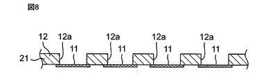
また、本実施の形態1では、保持体12が膜部11の両方の主面に接続されるように構成したが、本発明はこれに限定されない。例えば、保持体12は、図8に示すように、膜部11の一方の主面にのみ接続されてもよい。この場合、膜部11の他方の主面に第2層状部材22を設ける必要がないので、構造をシンプルにしてコストの低減を図ることができる。また、保持体12の可撓性を向上させることができる。
また、本実施の形態1では、濾過対象物が液体に含まれる生物由来物質であるとしたが、本発明はこれに限定されない。例えば、液体に含まれるサイズの大きな異物を濾過対象物としてもよい。また、濾過対象物は、気体に含まれる物質であってもよい。すなわち、濾過対象物は、流体に含まれる物質であればよく、例えば、空気中に含まれるPM2.5であってもよい。
また、本実施の形態1では、濾過フィルタ群1及び濾過装置2は、液体から生物由来物質を濾過するために使用されるものとしたが、本発明はこれに限定されない。例えば、濾過フィルタ群1及び濾過装置2は、例えば、液体に含まれる成分を濃縮するために使用されてもよい。
また、本実施の形態1では、流体供給部4は、第1筒体41と第2筒体42の一組の筒体で構成されるものとしたが、本発明はこれに限定されない。流体供給部4は、第1筒体41と第2筒体42とを一組として、複数組の筒体で構成されてもよい。この構成によれば、生物由来物質を含む液体を複数の膜部11で同時に濾過することができ、濾過処理量の増加及び濾過時間の短縮を図ることが可能になる。
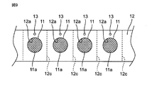
なお、保持体12には、図9に示すように、互いに隣接する貫通穴12a,12aの間に切取線12cが設けられてもよい。この構成によれば、切取線12cに沿って切り取ることで、所望の長さの濾過フィルタ群1を得ることができる。例えば、生物由来物質を濾過した膜部11を含む保持体12の一部を切取線12cで切り取って、顕微鏡などで分析することが可能になる。
また、保持体12には、図9に示すように、複数の送り穴13が設けられてもよい。複数の送り穴13は、例えば、保持体12の長手方向に沿って等間隔に設ければよい。また、この場合、例えば、複数の送り穴13に対応する複数のピンを備えるホイール(図示せず)を搬送装置3が備えるように構成すればよい。これにより、濾過フィルタ群1を所望の距離だけより正確に搬送することが可能になり、流体供給領域E1に膜部11を位置させる精度を向上させることができる。
また、図10に示すように、保持体12(濾過フィルタ群1)をロール状に巻いたロール体5の最外周面に保護シート14が設けられてもよい。また、当該ロール体5の互いに対向する一対の底面5A,5Bの少なくとも一方に保護シート(図示せず)が設けられてもよい。この構成によれば、濾過フィルタ群の搬送が容易になるだけでなく、濾過フィルタ群に対する汚れや破損を防ぐことができる。
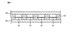
また、図11に示すように、保持体12の両方の主面には、複数箇所で露出する膜部11を覆う保護シート15が設けられてもよい。この構成によれば、濾過フィルタ群1に対する汚れや破損を防ぐことができる。なお、保護シート15は、例えば、保持体12をロール状に巻く場合には、保持体12の一方の主面にのみ設けられてもよい。この構成によれば、保持体12の可撓性を向上させることができる。
なお、各保護シートは、例えば、ポリスチレン、ポリエチレン、ポリエステル、ポリウレタン、レーヨン、PVC、ハイドロゲル、ナイロン、ポリオレフィン、セルロースなどの可撓性を有する部材で構成すればよい。なお、各保護シートの材料は、ガンマ線照射、オートクレーブ、エチレンガスなど各種滅菌が可能な材料であることがより好ましい。このような材料としては、例えば、ポリエステル、ポリウレタン、ポリ塩化ビニルが挙げられる。
(実施の形態2)
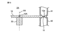
図12は、本発明の実施の形態2に係る濾過フィルタ群、及び当該濾過フィルタ群を用いる濾過装置の概略構成を示す平面図であり、図13は、そのD1―D1線断面図である。
図12は、本発明の実施の形態2に係る濾過フィルタ群、及び当該濾過フィルタ群を用いる濾過装置の概略構成を示す平面図であり、図13は、そのD1―D1線断面図である。
本実施の形態2に係る濾過フィルタ群1Aが前記実施の形態1に係る濾過フィルタ群1と異なる点は、保持体12が円盤状に形成され、複数の膜部11が保持体12の外周部に沿って配置されている点である。本実施の形態2において、複数の膜部11は、保持体12の中心穴12Aを中心とする同心円上に等間隔に配置されている。
また、本実施の形態2に係る濾過装置2Aが前記実施の形態1に係る濾過装置2と異なる点は、搬送装置3が保持体12を回転させるように構成されている点である。本実施の形態2において、搬送装置3は、保持体12の中心穴12Aに挿入される回転体33を備えている。回転体33が回転軸R1を中心として回転(例えば、図12の矢印の方向に回転)することにより、流体供給領域E1に位置する膜部11が逐次変更される。
本実施の形態2によれば、前記実施の形態1と同様に、複数の膜部11を1つの保持体12で保持するようにしている。これにより、特定の膜部11が目詰まりした場合でも、保持体12を移動させるだけで他の膜部11に交換することができる。従って、濾過フィルタの交換を容易に行うことができる。
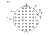
なお、本実施の形態2では、複数の膜部11を保持体12の中心穴12Aを中心とする円上に等間隔に配置したが、本発明はこれに限定されない。図14に示す濾過フィルタ群1Bのように、複数の膜部11は、保持体12の全体に分散(例えば、均一に分散)して設けられてもよい。この場合、搬送装置3は、保持体12を平行移動させることにより流体供給領域E1に位置する膜部11を逐次変更するように構成されればよい。また、搬送装置3は、流体供給部4を移動させることにより流体供給領域E1に位置する膜部11を逐次変更するように構成されてもよい。
(実施の形態3)
図15は、本発明の実施の形態3に係る濾過装置の概略構成を示す斜視図である。
図15は、本発明の実施の形態3に係る濾過装置の概略構成を示す斜視図である。
本実施の形態3に係る濾過装置2Bが前記実施の形態1に係る濾過装置2と異なる点は、流体供給部4が回転体43を備えている点である。
本実施の形態3において、濾過フィルタ群1は、回転筒体43の外周面に螺旋状に巻かれるように配置される。回転筒体43は、回転軸R2を中心として回転する。これにより、濾過フィルタ群1は、回転筒体43の外周面に沿って螺旋状に移動する。
回転筒体43の外周面には、濾過フィルタ群1の複数の膜部11に対向する位置にそれぞれ、貫通穴43aが設けられている。生物由来物質を含む液体は、回転筒体43の一方の開口端部43bから他方の開口端部43cに向けて回転軸R1に対して平行又は略平行に供給される。この過程で、生物由来物質を含む液体の一部が、貫通穴43aを介して膜部11を通過し、当該膜部11が生物由来物質を濾過する。
本実施の形態3によれば、膜部11に対して生物由来物質を含む液体を平行又は略平行に供給するので、膜部11の目詰まりの発生を抑制することができる。
(実施の形態4)
図16は、本発明の実施の形態4に係る濾過装置の概略構成を示す側面図である。
図16は、本発明の実施の形態4に係る濾過装置の概略構成を示す側面図である。
本実施の形態4に係る濾過装置2Cが前記実施の形態1に係る濾過装置2と異なる点は、搬送装置3が濾過フィルタ群1を時計回り又は反時計回りに搬送するように構成され、生物由来物質を含む液体中を濾過フィルタ群1が通過するように構成されている点である。なお、図16は、搬送装置3が濾過フィルタ群1を時計回りに搬送する例を示している。
本実施の形態4において、搬送装置3は、図16に示すように、4つのガイドローラ34~37を備えている。濾過フィルタ群1は、無端ベルト状に形成され、4つのガイドローラ34~37に環状に掛け回されている。ガイドローラ34~37の少なくとも1つには、回転モータ(図示せず)が設けられている。当該回転モータが駆動することにより、ガイドローラ34~37が回転し、濾過フィルタ群1が搬送される。
ガイドローラ34とガイドローラ35との間には、濾過フィルタ群1の各膜部11に生物由来物質51を含む液体52を供給する流体供給領域E1が設けられている。当該流体供給領域E1には、流体供給部として凹部44が設けられている。凹部44には、生物由来物質51を含む液体52が溜められている。生物由来物質51は、濾過フィルタ群1が凹部44に沿って搬送され液体52中を通過することによって、濾過フィルタ群1の各膜部11に濾過される。
ガイドローラ36とガイドローラ37との間には、濾過された生物由来物質51を膜部11上から除去(いわゆる、逆洗)する除去領域E2が設けられている。除去領域E2には、例えば、濾過フィルタ群1にエアを吹き付けるブロア(図示せず)が設けられている。当該ブロアが生物由来物質51が付着した膜部11の表面とは反対側の面からエアを吹き付けることにより、生物由来物質51が膜部11から除去される。当該除去された生物由来物質51は、容器6内に蓄積される。
生物由来物質51が除去された膜部11は、ガイドローラ34~37の回転により濾過フィルタ群1が搬送されることにより、再び流体供給領域E1に搬送され、液体52中の生物由来物質51を濾過する。以後、同様にして、ガイドローラ34~37の回転により濾過フィルタ群1が搬送されることにより、各膜部11は、流体供給領域E1と除去領域E2とに交互に搬送され、生物由来物質51の濾過と除去が交互に繰り返される。
本実施の形態4によれば、濾過フィルタ群1を時計回り又は反時計回りの一方向に搬送することにより、濾過フィルタの交換を容易に行うことができる。
また、本実施の形態4によれば、濾過した生物由来物質51で目詰まりした膜部11を除去領域E2に移動させて生物由来物質51を除去するようにしている。これにより、膜部11を再利用することができ、コストの低減を図ることができる。
なお、本実施の形態4では、濾過フィルタ群1を時計回り又は反時計回りの一方向に搬送することにより、各膜部11を流体供給領域E1と除去領域E2とに交互に搬送するようにしたが、本発明はこれに限定されない。例えば、濾過フィルタ群1を一方向に搬送して各膜部11を流体供給領域E1に搬送した後、濾過フィルタ群1を逆方向に搬送して各膜部11を除去領域E2に搬送する動作を繰り返すようにしてもよい。
また、流体供給領域E1と除去領域E2の間に滅菌工程を設けても良い。本実施の形態4では膜部11を再利用することができるが、滅菌工程を設けることにより、異物混入(コンタミネーション)を低減することができる。
また、本実施の形態4では、濾過フィルタ群1にエアを吹き付けることにより膜部11から生物由来物質51を除去するものとしたが、本発明はこれに限定されない。例えば、重力を利用して、膜部11から生物由来物質51を除去するようにしてもよい。また、エアを吹き付ける代わりに液体を用いて逆洗しても良い。
なお、前記様々な実施の形態のうちの任意の実施の形態を適宜組み合わせることにより、それぞれの有する効果を奏するようにすることができる。
本発明は、添付図面を参照しながら好ましい実施形態に関連して充分に記載されているが、この技術の熟練した人々にとっては種々の変形や修正は明白である。そのような変形や修正は、添付した請求の範囲による本発明の範囲から外れない限りにおいて、その中に含まれると理解されるべきである。
本発明は、濾過フィルタの交換をより容易に行うことができるので、生物由来物質やPM2.5などの流体に含まれる濾過対象物を濾過する濾過フィルタ群、及び当該濾過フィルタ群を用いる濾過装置に有用である。
1,1A,1B 濾過フィルタ群
2,2A,2B,2C 濾過装置
3 搬送装置
4 流体供給部
5 ロール体
6 容器
11 膜部
11a 貫通孔
12 保持体
12a 貫通穴
12b 凹部
12c 切取線
12A 中心穴
13 送り穴
14,15 保護シート
21 第1層状部材
22 第2層状部材
31 供給リール
32 巻き取りリール
33 回転体
41 第1筒体
42 第2筒体
43 回転筒体
44 凹部
51 生物由来物質
52 液体
2,2A,2B,2C 濾過装置
3 搬送装置
4 流体供給部
5 ロール体
6 容器
11 膜部
11a 貫通孔
12 保持体
12a 貫通穴
12b 凹部
12c 切取線
12A 中心穴
13 送り穴
14,15 保護シート
21 第1層状部材
22 第2層状部材
31 供給リール
32 巻き取りリール
33 回転体
41 第1筒体
42 第2筒体
43 回転筒体
44 凹部
51 生物由来物質
52 液体
Claims (18)
- 流体に含まれる濾過対象物を濾過する膜部と、
前記膜部を保持するとともに、前記膜部を複数箇所で露出させるための複数の貫通穴が設けられている保持体と、
を備える、濾過フィルタ群。 - 前記膜部は、前記複数の貫通穴のそれぞれに対応するように複数設けられている、請求項1に記載の濾過フィルタ群。
- 前記複数の膜部は、それぞれ外周部を前記保持体に保持されている、請求項2に記載の濾過フィルタ群。
- 前記保持体は、前記膜部の一方の主面に接続されている、請求項1~3のいずれか1つに記載の濾過フィルタ群。
- 前記保持体は、前記膜部の一方の主面及び他方の主面の両方に接続されている、請求項1~3のいずれか1つに記載の濾過フィルタ群。
- 前記膜部は、前記保持体により挟持されている、請求項5に記載の濾過フィルタ群。
- 前記保持体は、前記膜部の外周部と嵌合する凹部を備える、請求項3に記載の濾過フィルタ群。
- 前記保持体は、可撓性を有するテープ状部材であり、
前記複数の貫通穴は、前記保持体の長手方向に沿って設けられている、
請求項1~7のいずれか1つに記載の濾過フィルタ群。 - 前記保持体には、互いに隣接する前記貫通穴の間に切取線が設けられている、請求項8に記載の濾過フィルタ群。
- 前記保持体の少なくとも一方の主面に、前記複数箇所で露出する膜部を覆う保護シートが設けられている、請求項1~9のいずれか1つに記載の濾過フィルタ群。
- 前記保持体をロール状に巻いたロール体の最外周面に保護シートが設けられている、請求項1~10のいずれか1つに記載の濾過フィルタ群。
- 前記保持体をロール状に巻いたロール体の互いに対向する一対の底面の少なくとも一方に保護シートが設けられている、請求項1~11のいずれか1つに記載の濾過フィルタ群。
- 前記膜部は、前記流体から生物由来物質を分離する複数の貫通孔を有する金属製薄膜である、請求項1~12のいずれか1つに記載の濾過フィルタ群。
- 流体に含まれる濾過対象物を濾過する膜部と、前記膜部を保持するとともに、前記膜部を複数箇所で露出させるための複数の貫通穴が設けられている保持体と、を備える濾過フィルタ群と、
前記複数の貫通穴のうちの少なくとも1つから露出する膜部に流体を供給する流体供給部と、
前記膜部に前記流体供給部からの流体が供給されるように前記濾過フィルタ群及び前記流体供給部の少なくとも一方を搬送する搬送装置と、
を備える、濾過装置。 - 前記搬送装置は、前記流体供給部が流体を供給する膜部が逐次変更されるように、前記濾過フィルタ群及び前記流体供給部の少なくとも一方を搬送する、請求項14に記載の濾過装置。
- 前記搬送装置は、前記流体供給部から流体を供給される流体供給領域と、濾過された濾過対象物を前記膜部上から除去する除去領域とに交互に前記膜部が位置するように、前記濾過フィルタ群を搬送する、請求項14又は15に記載の濾過装置。
- 前記濾過フィルタ群は、無端ベルト状に形成され、
前記搬送装置は、前記濾過フィルタ群を時計回り又は反時計回りに搬送する、請求項14~16のいずれか1つに記載の濾過装置。 - 前記流体供給部は、前記濾過フィルタ群を介して互いに対向する第1筒体及び第2筒体を備え、
前記第1筒体と前記第2筒体とは、互いに近づく方向及び互いに離れる方向に移動可能に構成されている、請求項14~16のいずれか1つに記載の濾過装置。
Applications Claiming Priority (2)
| Application Number | Priority Date | Filing Date | Title |
|---|---|---|---|
| JP2015-124776 | 2015-06-22 | ||
| JP2015124776A JP2018122194A (ja) | 2015-06-22 | 2015-06-22 | 濾過フィルタ群及び濾過装置 |
Publications (1)
| Publication Number | Publication Date |
|---|---|
| WO2016208387A1 true WO2016208387A1 (ja) | 2016-12-29 |
Family
ID=57585628
Family Applications (1)
| Application Number | Title | Priority Date | Filing Date |
|---|---|---|---|
| PCT/JP2016/067001 Ceased WO2016208387A1 (ja) | 2015-06-22 | 2016-06-08 | 濾過フィルタ群及び濾過装置 |
Country Status (2)
| Country | Link |
|---|---|
| JP (1) | JP2018122194A (ja) |
| WO (1) | WO2016208387A1 (ja) |
Families Citing this family (2)
| Publication number | Priority date | Publication date | Assignee | Title |
|---|---|---|---|---|
| WO2016208459A1 (ja) * | 2015-06-22 | 2016-12-29 | 株式会社村田製作所 | 濾過装置、濾過方法、及び濾過フィルタ |
| KR102202861B1 (ko) * | 2019-04-09 | 2021-01-18 | 이준석 | 스크린 교환 장치, 이를 포함하는 생체조직 미세화 시스템, 이를 이용하는 생체조직 미세화 방법 및 이와 관련된 생체조직으로부터 타겟 물질을 분리하는 방법 |
Citations (6)
| Publication number | Priority date | Publication date | Assignee | Title |
|---|---|---|---|---|
| JPH09230056A (ja) * | 1996-02-23 | 1997-09-05 | Toshiba Corp | ダストサンプラ用ろ紙 |
| JP2001264234A (ja) * | 2000-03-17 | 2001-09-26 | Matsushita Electric Ind Co Ltd | 花粉検出装置 |
| JP2003149126A (ja) * | 2001-11-19 | 2003-05-21 | Horiba Ltd | 浮遊粒子状物質濃度測定装置およびこの装置に用いるフィルタテープの管理方法 |
| JP2004012199A (ja) * | 2002-06-04 | 2004-01-15 | Horiba Ltd | 浮遊粒子状物質濃度測定装置および方法ならびに浮遊粒子状物質濃度測定用フィルタテープ |
| JP2010019724A (ja) * | 2008-07-11 | 2010-01-28 | Hitachi Ltd | ダスト放射線モニタ |
| JP2014163906A (ja) * | 2013-02-27 | 2014-09-08 | Hitachi Ltd | 微粒子分析装置 |
-
2015
- 2015-06-22 JP JP2015124776A patent/JP2018122194A/ja active Pending
-
2016
- 2016-06-08 WO PCT/JP2016/067001 patent/WO2016208387A1/ja not_active Ceased
Patent Citations (6)
| Publication number | Priority date | Publication date | Assignee | Title |
|---|---|---|---|---|
| JPH09230056A (ja) * | 1996-02-23 | 1997-09-05 | Toshiba Corp | ダストサンプラ用ろ紙 |
| JP2001264234A (ja) * | 2000-03-17 | 2001-09-26 | Matsushita Electric Ind Co Ltd | 花粉検出装置 |
| JP2003149126A (ja) * | 2001-11-19 | 2003-05-21 | Horiba Ltd | 浮遊粒子状物質濃度測定装置およびこの装置に用いるフィルタテープの管理方法 |
| JP2004012199A (ja) * | 2002-06-04 | 2004-01-15 | Horiba Ltd | 浮遊粒子状物質濃度測定装置および方法ならびに浮遊粒子状物質濃度測定用フィルタテープ |
| JP2010019724A (ja) * | 2008-07-11 | 2010-01-28 | Hitachi Ltd | ダスト放射線モニタ |
| JP2014163906A (ja) * | 2013-02-27 | 2014-09-08 | Hitachi Ltd | 微粒子分析装置 |
Also Published As
| Publication number | Publication date |
|---|---|
| JP2018122194A (ja) | 2018-08-09 |
Similar Documents
| Publication | Publication Date | Title |
|---|---|---|
| JP6693583B2 (ja) | 濾過装置、濾過方法、及び濾過フィルタ | |
| US20240018462A1 (en) | Metallic porous membrane, classifying method using the same, and classifying device | |
| CN103237582B (zh) | 滤筒 | |
| EP2318125B1 (en) | Cross-flow filtration apparatus with biocidal feed spacer | |
| ES2734309T3 (es) | Método automatizado de fabricación de frotis | |
| WO2016208387A1 (ja) | 濾過フィルタ群及び濾過装置 | |
| CN114891608A (zh) | 用于过滤有核细胞的过滤器和使用了其的过滤方法 | |
| KR101279628B1 (ko) | 적층형 디스크 필터 및 이를 이용한 여과기 | |
| JPWO2018163757A1 (ja) | 細胞濾過フィルタ | |
| WO2019181106A1 (ja) | 濾過装置 | |
| US20220162539A1 (en) | Filtration and collection device | |
| JP6930068B2 (ja) | 中空糸モジュールを用いる細胞培養方法 | |
| JP4555650B2 (ja) | 細胞給排・捕捉装置及び細胞給排・捕捉方法 | |
| JP2010510802A (ja) | 細胞アレイ又はマトリクスアセンブリ及びエレクトロポレーション | |
| US11498032B2 (en) | Concentration apparatus | |
| US11833455B2 (en) | Separation recovery system and separation recovery method | |
| DE102009039535A1 (de) | Behälter, Vorrichtung und Verfahren zur Behandlung von Gewebe unter Reinraumbedingungen | |
| JP2011062696A (ja) | 中空糸膜モジュール及びそれを用いた水処理装置 | |
| US20190118120A1 (en) | Sampling filter, sampling device, and sampling method using the same | |
| JP7422639B2 (ja) | 培地交換用フィルター及びこのフィルターを有する培養装置 | |
| TWI915491B (zh) | 積層體之製造方法、高分子薄膜之製造方法、及積層體 | |
| CN120677368A (zh) | 过滤装置、过滤系统及过滤方法 | |
| JP2024081543A (ja) | 培養システム及び培養方法 | |
| JP6815307B2 (ja) | 有核細胞の濾過用フィルターおよびそれを用いた濾過方法 | |
| JP6394088B2 (ja) | 細胞シート製造用容器 |
Legal Events
| Date | Code | Title | Description |
|---|---|---|---|
| 121 | Ep: the epo has been informed by wipo that ep was designated in this application |
Ref document number: 16814158 Country of ref document: EP Kind code of ref document: A1 |
|
| NENP | Non-entry into the national phase |
Ref country code: DE |
|
| NENP | Non-entry into the national phase |
Ref country code: JP |
|
| 122 | Ep: pct application non-entry in european phase |
Ref document number: 16814158 Country of ref document: EP Kind code of ref document: A1 |