WO2016208163A1 - Gas treatment apparatus - Google Patents
Gas treatment apparatus Download PDFInfo
- Publication number
- WO2016208163A1 WO2016208163A1 PCT/JP2016/002914 JP2016002914W WO2016208163A1 WO 2016208163 A1 WO2016208163 A1 WO 2016208163A1 JP 2016002914 W JP2016002914 W JP 2016002914W WO 2016208163 A1 WO2016208163 A1 WO 2016208163A1
- Authority
- WO
- WIPO (PCT)
- Prior art keywords
- replacement
- detector
- resistance
- treatment apparatus
- gas treatment
- Prior art date
- Legal status (The legal status is an assumption and is not a legal conclusion. Google has not performed a legal analysis and makes no representation as to the accuracy of the status listed.)
- Ceased
Links
Images



Classifications
-
- C—CHEMISTRY; METALLURGY
- C25—ELECTROLYTIC OR ELECTROPHORETIC PROCESSES; APPARATUS THEREFOR
- C25B—ELECTROLYTIC OR ELECTROPHORETIC PROCESSES FOR THE PRODUCTION OF COMPOUNDS OR NON-METALS; APPARATUS THEREFOR
- C25B1/00—Electrolytic production of inorganic compounds or non-metals
- C25B1/01—Products
- C25B1/02—Hydrogen or oxygen
- C25B1/04—Hydrogen or oxygen by electrolysis of water
-
- A—HUMAN NECESSITIES
- A61—MEDICAL OR VETERINARY SCIENCE; HYGIENE
- A61M—DEVICES FOR INTRODUCING MEDIA INTO, OR ONTO, THE BODY; DEVICES FOR TRANSDUCING BODY MEDIA OR FOR TAKING MEDIA FROM THE BODY; DEVICES FOR PRODUCING OR ENDING SLEEP OR STUPOR
- A61M16/00—Devices for influencing the respiratory system of patients by gas treatment, e.g. ventilators; Tracheal tubes
- A61M16/10—Preparation of respiratory gases or vapours
- A61M16/12—Preparation of respiratory gases or vapours by mixing different gases
-
- C—CHEMISTRY; METALLURGY
- C25—ELECTROLYTIC OR ELECTROPHORETIC PROCESSES; APPARATUS THEREFOR
- C25B—ELECTROLYTIC OR ELECTROPHORETIC PROCESSES FOR THE PRODUCTION OF COMPOUNDS OR NON-METALS; APPARATUS THEREFOR
- C25B11/00—Electrodes; Manufacture thereof not otherwise provided for
- C25B11/02—Electrodes; Manufacture thereof not otherwise provided for characterised by shape or form
-
- C—CHEMISTRY; METALLURGY
- C25—ELECTROLYTIC OR ELECTROPHORETIC PROCESSES; APPARATUS THEREFOR
- C25B—ELECTROLYTIC OR ELECTROPHORETIC PROCESSES FOR THE PRODUCTION OF COMPOUNDS OR NON-METALS; APPARATUS THEREFOR
- C25B15/00—Operating or servicing cells
- C25B15/02—Process control or regulation
-
- C—CHEMISTRY; METALLURGY
- C25—ELECTROLYTIC OR ELECTROPHORETIC PROCESSES; APPARATUS THEREFOR
- C25B—ELECTROLYTIC OR ELECTROPHORETIC PROCESSES FOR THE PRODUCTION OF COMPOUNDS OR NON-METALS; APPARATUS THEREFOR
- C25B9/00—Cells or assemblies of cells; Constructional parts of cells; Assemblies of constructional parts, e.g. electrode-diaphragm assemblies; Process-related cell features
-
- A—HUMAN NECESSITIES
- A61—MEDICAL OR VETERINARY SCIENCE; HYGIENE
- A61M—DEVICES FOR INTRODUCING MEDIA INTO, OR ONTO, THE BODY; DEVICES FOR TRANSDUCING BODY MEDIA OR FOR TAKING MEDIA FROM THE BODY; DEVICES FOR PRODUCING OR ENDING SLEEP OR STUPOR
- A61M16/00—Devices for influencing the respiratory system of patients by gas treatment, e.g. ventilators; Tracheal tubes
- A61M16/10—Preparation of respiratory gases or vapours
- A61M16/1005—Preparation of respiratory gases or vapours with O2 features or with parameter measurement
- A61M2016/102—Measuring a parameter of the content of the delivered gas
-
- A—HUMAN NECESSITIES
- A61—MEDICAL OR VETERINARY SCIENCE; HYGIENE
- A61M—DEVICES FOR INTRODUCING MEDIA INTO, OR ONTO, THE BODY; DEVICES FOR TRANSDUCING BODY MEDIA OR FOR TAKING MEDIA FROM THE BODY; DEVICES FOR PRODUCING OR ENDING SLEEP OR STUPOR
- A61M2202/00—Special media to be introduced, removed or treated
- A61M2202/02—Gases
- A61M2202/0208—Oxygen
-
- A—HUMAN NECESSITIES
- A61—MEDICAL OR VETERINARY SCIENCE; HYGIENE
- A61M—DEVICES FOR INTRODUCING MEDIA INTO, OR ONTO, THE BODY; DEVICES FOR TRANSDUCING BODY MEDIA OR FOR TAKING MEDIA FROM THE BODY; DEVICES FOR PRODUCING OR ENDING SLEEP OR STUPOR
- A61M2205/00—General characteristics of the apparatus
- A61M2205/12—General characteristics of the apparatus with interchangeable cassettes forming partially or totally the fluid circuit
-
- A—HUMAN NECESSITIES
- A61—MEDICAL OR VETERINARY SCIENCE; HYGIENE
- A61M—DEVICES FOR INTRODUCING MEDIA INTO, OR ONTO, THE BODY; DEVICES FOR TRANSDUCING BODY MEDIA OR FOR TAKING MEDIA FROM THE BODY; DEVICES FOR PRODUCING OR ENDING SLEEP OR STUPOR
- A61M2205/00—General characteristics of the apparatus
- A61M2205/33—Controlling, regulating or measuring
- A61M2205/3317—Electromagnetic, inductive or dielectric measuring means
-
- A—HUMAN NECESSITIES
- A61—MEDICAL OR VETERINARY SCIENCE; HYGIENE
- A61M—DEVICES FOR INTRODUCING MEDIA INTO, OR ONTO, THE BODY; DEVICES FOR TRANSDUCING BODY MEDIA OR FOR TAKING MEDIA FROM THE BODY; DEVICES FOR PRODUCING OR ENDING SLEEP OR STUPOR
- A61M2205/00—General characteristics of the apparatus
- A61M2205/35—Communication
- A61M2205/3576—Communication with non implanted data transmission devices, e.g. using external transmitter or receiver
- A61M2205/3592—Communication with non implanted data transmission devices, e.g. using external transmitter or receiver using telemetric means, e.g. radio or optical transmission
-
- A—HUMAN NECESSITIES
- A61—MEDICAL OR VETERINARY SCIENCE; HYGIENE
- A61M—DEVICES FOR INTRODUCING MEDIA INTO, OR ONTO, THE BODY; DEVICES FOR TRANSDUCING BODY MEDIA OR FOR TAKING MEDIA FROM THE BODY; DEVICES FOR PRODUCING OR ENDING SLEEP OR STUPOR
- A61M2205/00—General characteristics of the apparatus
- A61M2205/50—General characteristics of the apparatus with microprocessors or computers
- A61M2205/502—User interfaces, e.g. screens or keyboards
-
- A—HUMAN NECESSITIES
- A61—MEDICAL OR VETERINARY SCIENCE; HYGIENE
- A61M—DEVICES FOR INTRODUCING MEDIA INTO, OR ONTO, THE BODY; DEVICES FOR TRANSDUCING BODY MEDIA OR FOR TAKING MEDIA FROM THE BODY; DEVICES FOR PRODUCING OR ENDING SLEEP OR STUPOR
- A61M2205/00—General characteristics of the apparatus
- A61M2205/70—General characteristics of the apparatus with testing or calibration facilities
- A61M2205/702—General characteristics of the apparatus with testing or calibration facilities automatically during use
-
- B—PERFORMING OPERATIONS; TRANSPORTING
- B01—PHYSICAL OR CHEMICAL PROCESSES OR APPARATUS IN GENERAL
- B01D—SEPARATION
- B01D2256/00—Main component in the product gas stream after treatment
- B01D2256/16—Hydrogen
-
- B—PERFORMING OPERATIONS; TRANSPORTING
- B01—PHYSICAL OR CHEMICAL PROCESSES OR APPARATUS IN GENERAL
- B01D—SEPARATION
- B01D53/00—Separation of gases or vapours; Recovering vapours of volatile solvents from gases; Chemical or biological purification of waste gases, e.g. engine exhaust gases, smoke, fumes, flue gases, aerosols
- B01D53/26—Drying gases or vapours
- B01D53/261—Drying gases or vapours by adsorption
-
- Y—GENERAL TAGGING OF NEW TECHNOLOGICAL DEVELOPMENTS; GENERAL TAGGING OF CROSS-SECTIONAL TECHNOLOGIES SPANNING OVER SEVERAL SECTIONS OF THE IPC; TECHNICAL SUBJECTS COVERED BY FORMER USPC CROSS-REFERENCE ART COLLECTIONS [XRACs] AND DIGESTS
- Y02—TECHNOLOGIES OR APPLICATIONS FOR MITIGATION OR ADAPTATION AGAINST CLIMATE CHANGE
- Y02E—REDUCTION OF GREENHOUSE GAS [GHG] EMISSIONS, RELATED TO ENERGY GENERATION, TRANSMISSION OR DISTRIBUTION
- Y02E60/00—Enabling technologies; Technologies with a potential or indirect contribution to GHG emissions mitigation
- Y02E60/30—Hydrogen technology
- Y02E60/36—Hydrogen production from non-carbon containing sources, e.g. by water electrolysis
Definitions
- the present invention relates to a gas treatment apparatus, and more particularly to a gas treatment apparatus in which a treatment gas is produced by electrolysis.
- the hydrogen gas is inhaled while being mixed with a gas that is used in medical treatment, such as air or oxygen.
- a gas that is used in medical treatment such as air or oxygen.
- hydrogen is contained in a mixed gas in about several PPM to several %.
- a treatment apparatus using hydrogen will be considered.
- PTL 1 discloses a hydrogen administration device that includes a hydrogen cylinder and an oxygen cylinder, and that administers a mixed gas in which hydrogen and oxygen are mixed with each other, to the patient.
- the hydrogen cylinder is used inside the device.
- the amount of a gas which can be stored in a gas cylinder is limited. In the case where the patient is treated over a predetermined period of time, therefore, the gas cylinder which is heavy and bulky must be replaced with another one.
- Patent Literature 2 discloses a method of inhalation into the body in which a hydrogen gas is generated by electrolysis, and the hydrogen gas is fed into the body of the patient through a nasal cannula.
- gas treatment apparatuses which use electrolysis such as the device disclosed by Patent Literature 2 do not teach nor suggest the replacement timing of electrodes. Therefore, there is a possibility that such a gas treatment apparatus continues to be used while being in a state where the treatment effect of the treatment gas (preferably, hydrogen) is insufficient.
- the treatment gas preferably, hydrogen
- a gas treatment apparatus comprising: an electrolysis unit which includes: a tank which is configured to hold a solution for electrolysis; and electrodes which are configured to electrolyze the solution to produce a treatment gas, the electrolysis unit which is to be attachable to and detachable from the gas treatment apparatus; a resistance detector which is configured to detect a state of a resistance of the electrodes; and a replacement detector which is configured to detect a timing of replacement of the electrolysis unit, based on the state of the resistance detected by the resistance detector.
- the resistance detector detects the resistance state of the electrodes.
- the resistance of the electrodes changes in response to deterioration due to the use time or attachment of impurities (such as mold or germs).
- the replacement detector detects the timing of replacement of the electrolysis unit, based on the resistance state of the electrodes. The replacement timing can be detected in this way, and therefore it is possible to avoid a situation where the electrolysis unit which is in an abnormal state (for example, a state where the treatment effect of the treatment gas is insufficient) continues to be used.
- the gas treatment apparatus continues to be used while being in a state where the treatment effect of the treatment gas (for example, hydrogen) is insufficient.
- the treatment gas for example, hydrogen
- Fig. 1 is a block diagram illustrating the configuration of a gas treatment apparatus 1 of Embodiment 1.
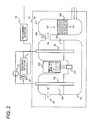
- Fig. 2 is a block diagram illustrating the configurations of an electrolysis unit 10 and peripheral processing sections in Embodiment 1.
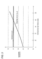
- Fig. 3 is a view illustrating the process concept of a replacement detector 15 the electrolysis unit 10 in Embodiment 1.
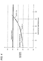
- Fig. 4 is a view illustrating the process concept of the replacement detector 15 in Embodiment 1.
- Fig. 5 is a view illustrating the process concept of the replacement detector 15 in Embodiment 1.
- Fig. 6 is a block diagram illustrating the configurations of the electrolysis unit 10 and peripheral processing sections in Embodiment 1.
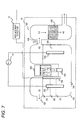
- Fig. 7 is a block diagram illustrating the configurations of the electrolysis unit 10 and peripheral processing sections in Embodiment 1.
- Fig. 8 is a block diagram illustrating the configuration of a gas treatment apparatus 1 of Embodiment 2.
- Fig. 1 is a block diagram illustrating the configuration of a gas treatment apparatus 1 of the embodiment.
- the gas treatment apparatus 1 produces a treatment gas (for example, hydrogen), mixes the treatment gas with another gas (air, oxygen, or the like), and feds the mixed gas into the body of the patient.
- the gas treatment apparatus 1 is a medical apparatus for producing a treatment gas and feeding the gas into the body of the patient. In the following, description will be made assuming that the treatment gas is hydrogen.
- the gas treatment apparatus 1 has an electrolysis unit 10, a gas feeding port 11, a mixing section 12, a current source 13, a resistance detector 14, a replacement detector 15, a notifying section 16, and a power source 19.
- the electrolysis unit 10 electrolyzes a solution (for example, pure water) to produce a hydrogen gas.
- the electrolysis unit 10 is a unit which is attachable to and detachable from the gas treatment apparatus 1 (apparatus main unit). Therefore, the gas treatment apparatus 1 may be considered as an apparatus in which the gas treatment apparatus is integrated with the electrolysis unit 10, and also as an apparatus with which the electrolysis unit 10 can be combined (an apparatus which does not include the electrolysis unit 10).
- the electrolysis unit 10 has a tank 200 which holds a solution for electrolysis, and an electrolysis section 100 which includes electrodes for electrolysis (an anode 103 and cathode 105 that will be described later).
- an electrolysis section 100 which includes electrodes for electrolysis (an anode 103 and cathode 105 that will be described later).
- Fig. 2 is a block diagram illustrating the configurations of the electrolysis unit 10 and the peripheral processing sections (the current source 13, the resistance detector 14, and the replacement detector 15).
- the tank 200 holds pure water. Pure water is water (H 2 O) from which impurities are removed away, and which does not contain chlorine (sterilizing and disinfecting component) or the like.
- the tank 200 may hold a solution in which sodium sulphate, sodium carbonate, or sodium hydrate is added to pure water, in place of pure water. That is, the tank 200 is requested to hold a solution for electrolysis.
- the electrolysis section 100 may include an electrolytic bath 101, a water feeding port 102, an anode 103, an anode chamber 104, a cathode 105, a cathode chamber 106, a discharging port 107, a discharging port 108, and a gas drying section 109.
- the pure water is poured from the tank 200 into the electrolytic bath 101 through the water feeding port 102.
- the pure water is supplied to the electrolytic bath 101 in such a manner that the electrolytic bath is not filled with the pure water.
- the embodiment is not limited to the configuration in which pure water is stored in the tank 200.
- tap water or the like may be stored in the tank 200, and a mechanism (ion-exchange resin or the like) which removes impurities of the tap water or the like may be disposed.
- the electrolytic bath 101 is partitioned into the anode chamber 104 in which the anode 103 is disposed, and the cathode chamber 106 in which the cathode 105 is disposed.
- each of the anode 103 and the cathode 105 is formed into a long rod-like shape as illustrated, and configured by using, for example, a titanium oxide electrode.
- the titanium oxide electrodes may be formed by powder metallurgy by using, for example, powder of titanium (Ti), titanium oxide (TiO 2 ), nickel (Ni), iron (Fe), chromium (Cr), and platinum (Pt).
- each of the titanium oxide electrodes may be formed by powder metallurgy to adsorb titanium (Ti) and titanium oxide (TiO 2 ) to the periphery of an electrode core member which is formed by a stainless steel rod.
- the material of the anode 103 and the cathode 105 is not limited to the above-described substances.
- the material for example, an allotrope of carbon, or a material which is attached to an allotrope of carbon, and in which a component for enhancing the electrode performance is doped may be used.
- the shape of each of the anode 103 and the cathode 105 is not limited to the above-described rod-like shape, and may be freely changed in accordance with the target performance to, for example, a planar shape, a mesh-like shape, or a coil-like shape.
- the current source 13 is connected to the anode 103 and the cathode 105.
- the current source 13 supplies a current to the anode 103 and the cathode 105. This causes the electrolysis unit 10 to produce a hydrogen gas (H 2 ) and an oxygen gas (O 2 ).
- a constant correlation between the energization time period and the resistance value is provided by a phenomenon in which the material is caused to dissolve by energization.
- the stainless steel round rods are used as the electrodes (the anode 103 and the cathode 105), for example, the stainless steel round rods are eroded by energization, and the diameters of the round rods are reduced by the degree corresponding to the total amount of the flowing current.
- the replacement detector 15 which will be described later can easily detect the replacement timing of the electrodes.
- the current source 13 is a constant current source.
- the current source 13 is a constant current source, even when the electrode resistance value is made unstable by deterioration of the electrodes or adhesion of impurities, a supply of hydrogen in which the supply amount is stabilized in accordance with the constant current flowing through the electrodes can be realized by Faraday's law of electrolysis.
- the replacement timing of the electrolysis unit 10 can be stably detected by the replacement detector 15 which will be described later.
- the current value output from the current source 13 is informed to the resistance detector 14 through a controller or the like which is not illustrated.
- the discharge port 107 from which the oxygen gas is discharged is disposed in an upper portion of the anode chamber 104.
- the discharge port 107 is requested to communicate with the exterior of the apparatus. Namely, a configuration where the oxygen gas is discharged to the outside is requested. Of course, a configuration where a mechanism for internally processing the oxygen gas is disposed may be employed.
- the discharge port 108 from which the hydrogen gas is discharged is disposed in an upper portion of the cathode chamber 106. As illustrated, the discharge port 108 may be configured so as to be coupled to the gas drying section 109.
- the gas drying section 109 dries the hydrogen gas discharged from the cathode chamber 106, and then supplies the dried hydrogen gas to the mixing section 12.
- the gas drying section 109 may be configured by, for example, silica gel.
- the configuration illustrated in Fig. 2 is one mode of a configuration which generates a hydrogen gas by electrolysis, and a configuration based on another technique (for example, electrolysis in which a different solution is used) may be employed as far as the configuration can safely generate a hydrogen gas.
- the resistance detector 14 detects the state of the resistance of the electrodes (the anode 103 and the cathode 105).
- the state of resistance preferably means the resistance value itself, it has a concept of including the increasing degree of the resistance value, the voltage value (and the increasing degree of the voltage value) having a proportional relationship to the resistance value, and the like.
- the resistance detector 14 incorporates a voltmeter 141.
- V voltage
- I current
- R resistance
- the current value (I) output from the current source 13 is input to the resistance detector 14.
- the voltmeter 141 detects the voltage value (V) across the electrodes (the anode 103 and the cathode 105).
- the resistance detector 14 may treat the voltage value (or the increasing degree of the voltage value) detected by the voltmeter 141 as the state of the resistance value of the electrodes (the anode 103 and the cathode 105).
- the resistance detector 14 is requested to detect the state of the resistance (the resistance value itself, a value having a proportional relationship to the resistance value, or the increasing degree of the resistance) of the electrodes (the anode 103 and the cathode 105). The detection will be further described in detail with reference to Figs. 3 to 5 and the like.
- the replacement detector 15 detects the replacement timing of the electrolysis unit 10 based on the state of the electrode resistance (the resistance value itself, the increasing degree of the resistance, or the like) detected by the resistance detector 14.
- the replacement timing has a concept including a timing when the electrolysis unit 10 is to be immediately replaced (i.e., the case where an abnormal state occurs), and also that when the electrolysis unit 10 will be replaced in future (for example, the electrolysis unit 10 is to be replaced about 5 hours later).
- Fig. 3 illustrates a voltage change of the electrodes in the case where the current source 13 is a constant current source. Since the current source 13 is a constant current source (I is constant), the electrode resistance (R) and the voltage value (V, the value detected by the voltmeter 141) have a proportional relationship.
- the resistance detector 14 notifies the replacement detector 15 of the voltage value (the value having a proportional relationship to the electrode resistance).
- the replacement detector 15 detects a timing when the voltage value exceeds a threshold value (in the example of Fig. 3, 4.0 V), as the replacement timing of the electrolysis unit 10. In the example of Fig. 3, the replacement detector 15 detects that the electrolysis unit 10 should be replaced after an elapse of about 80 hours from the start of energization.
- the resistance detector 14 may calculate the resistance value (R) itself by dividing the voltage value (V) by the current value (I) of the current source 13 (constant current source).
- the replacement detector 15 may compare the resistance value (R) with a predetermined threshold value, thereby detecting the replacement timing.
- Fig. 4 is a view illustrating a modification of the detection of the replacement timing by the replacement detector 15.
- Fig. 4 illustrates a voltage change of the electrodes in the case where the current source 13 is a constant current source.
- the resistance detector 14 continuously detects the voltage value (the value having a proportional relationship to the electrode resistance), and notifies the replacement detector 15 of the voltage value. From a transition of the voltage value, the replacement detector 15 detects the slope of a voltage value curve at each time.
- the replacement detector 15 detects the replacement timing while considering also the slope. At the timing when the slope of the voltage value curve is increased to 1.4 times or more the slope at a certain timing (in the example, after an elapse of 40 hours from the start of energization), for example, the replacement detector 15 determines that the electrolysis unit 10 is to be replaced (the replacement timing has come).
- the replacement detector 15 determines that the electrolysis unit 10 is to be replaced (the replacement timing has come), without performing the comparison with the threshold value.
- the replacement detector 15 may detect the timing when the slope is equal to or larger than a predetermined threshold value, as the replacement timing.
- the above-described slope has a value reflecting the deterioration rate of the electrodes (the anode 103 and the cathode 105). In the case where the slope is steep, therefore, it is presumed that deterioration of the electrodes (the anode 103 and the cathode 105) is accelerated for any reason. Since the replacement detector 15 detects the replacement timing while considering the slope, it is possible to early detect an abnormal state. Although, in the example of Fig. 4, the replacement detector 15 detects the replacement timing based on the slope of the voltage value curve, the detection value of the resistance value may be calculated, and then the replacement timing may be detected by using the slope of a resistance value curve.
- Fig. 5 is a view illustrating a technique in which a future timing of replacement of the electrolysis unit 10 is detected by the replacement detector 15.
- a change of the electrode voltage in the case where the current source 13 is a constant current source is illustrated.
- the resistance detector 14 continuously detects the voltage value (the value having a proportional relationship to the electrode resistance) in the time period from the start of energization to an elapse of 40 hours, and notifies the replacement detector 15 of the voltage value.
- the replacement detector 15 determines that the replacement timing has not yet come. Consequently, the replacement detector 15 detects a timing when the electrolysis unit 10 is to be replaced in future, based on a transition of the voltage value curve (a temporal change of the voltage value). In the case where the voltage value curve transits in a similar manner as a linear curve as illustrated in Fig. 5 (the slope does not change), for example, the replacement detector 15 may first obtain the expression of the linear curve, and then detect the timing when the voltage value reaches the threshold value, by using the expression of the linear curve. In the example of Fig. 5, the replacement detector 15 detects the timing when 80 hours elapse from the start of energization (40 hours later from now), as the replacement timing of the electrolysis unit 10.
- the replacement detector 15 may detect the replacement timing with assuming that deterioration of the electrodes (the anode 103 and the cathode 105) will be accelerated in future. For example, the replacement detector 15 may detect "about 75 hours later" which is obtained by subtracting a predetermined time period (for example, 5 hours) from “timing when 80 hours elapse from the start of energization (40 hours later from now)," as the replacement timing of the electrolysis unit 10.
- a predetermined time period for example, 5 hours
- the replacement detector 15 may detect a timing (replacement timing) when the electrolysis unit 10 is to be replaced in future, in view of the transition of the slope of the voltage value curve.
- the replacement detector 15 may obtain the resistance value and a resistance value curve by using Ohm's Law, and then detect a timing (replacement timing) when the electrolysis unit 10 is to be replaced in future.
- the embodiment is not limited to this.
- the replacement detector 15 may detect the replacement timing without considering the stop time periods.
- the power source 19 supplies the driving power to the processing sections in the gas treatment apparatus 1.
- the power source 19 may be connected to a commercial power outlet to ensure the power supply.
- the mixing section 12 produces a mixed gas in which the hydrogen produced by the electrolysis unit 10, and the treatment gas (such as air or oxygen) supplied through the gas feeding port 11 are mixed with each other.
- the mixed gas is fed into the body of the patient through a nasal cannula or the like.
- the mixing section 12 may incorporate a mass flow controller and the like to adjust the concentration of hydrogen or the like to a desired value.
- the notifying section 16 has a displaying section 17 and a sound emitter 18.
- the notifying section 16 performs various notifications relating to the replacement timing of the electrolysis unit 10 which is detected by the replacement detector 15.
- the displaying section 17 is configured by a display device which is disposed, for example, on the housing of the gas treatment apparatus 1, peripheral circuits, etc.
- the displaying section 17 displays a message expediting replacement (for example, a message such as "Time for replacement has come. Replace the electrolysis unit 10 with fresh one.”).
- the displaying section 17 may be configured by an indicator lamp disposed on the gas treatment apparatus 1.
- the displaying section 17 may perform a display such as turning on of the indicator lamp. As described above, the displaying section 17 may perform any kind of display expediting replacement of the electrolysis unit 10.
- the displaying section 17 may display a future timing of replacement of the electrolysis unit 10 which is detected by the replacement detector 15. For example, the displaying section 17 may display a message such as "Replace the electrolysis unit about 20 hours later.”
- the sound emitter 18 is configured by a so-called speaker, peripheral circuits, etc.
- the replacement detector 15 detects that the replacement timing of the electrolysis unit 10 has passed, the sound emitter 18 acoustically outputs a message expediting replacement.
- the message may be "Replace the electrolysis unit with fresh one.” or a mere beep sound or the like.
- the notification by the notifying section 16 is not limited to visual or audio notification, and the notifying section 16 may notify that the electrolysis unit 10 is to be replaced, by any method.
- the notifying section 16 may transmit a text message expediting replacement of the electrolysis unit 10, to an external apparatus in conjunction with a network function which is not illustrated.
- the notifying section 16 may transmit a mail to, for example, a terminal of the nurse or the like, and a central monitor in a hospital ward. This enables the nurse or the like to promptly replace the electrolysis unit 10 with a fresh one.
- the notifying section 16 notifies of the replacement timing by any method, replacement of the electrolysis unit 10 can be smoothly performed without omission.
- the replacement detector 15 may control the electrolysis unit 10 so that the operation of the electrolysis unit 10 itself is suspended.
- the operation of the current source 13 may be suspended, and this allows the production of the effective treatment gas to be always ensured.
- the resistance detector 14 detects the state of the resistance (the resistance value itself, the increasing degree of the resistance, or a voltage value having a proportional relationship to the resistance, or the like) of the electrodes.
- the resistance of the electrodes is increased change in response to deterioration due to the operating time or attachment of impurities (such as mold or germs).
- the replacement detector 15 detects the timing of replacement of the electrolysis unit 10, based on the state of the resistance of the electrodes. The replacement timing can be detected in this way, and therefore it is possible to avoid a situation where the electrolysis unit 10 which is in an abnormal state (for example, a state where the treatment effect of the treatment gas is insufficient) continues to be used.
- the resistance detector 14 can detect a change of the resistance of the electrode, based only on the voltage value measured by the voltmeter 141. That is, it is possible to easily know the state of the resistance of the electrodes, while using the simple configuration 1.e., the voltmeter 141.
- the replacement detector 15 can detect whether the replacement timing has passed in the electrolysis unit 10 or not, by performing only the simple process in which the voltage value is compared with the predetermined threshold value (in the example of Fig. 3, 4 V) (Fig. 3).
- the replacement detector 15 can detect replacement timing when the electrolysis unit 10 is to be replaced in future, based on the comparison of a temporal change of the voltage value with the threshold value (Fig. 5).
- the user can know an indication of the timing when the electrolysis unit 10 is to be replaced.
- the resistance detector 14 can detect the resistance value of the electrodes, simply by dividing the voltage value by the current value of the current source 13. By using the detected resistance value, the replacement detector 15 can easily detect the replacement timing of the electrolysis unit 10.
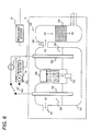
- Fig. 6 is a view illustrating a second configuration example of the electrolysis unit 10.
- the resistance detector 14 incorporates an ohmmeter 142.
- the anode 103 is connected to a switch 143.
- the switch 143 is connected to either of the current source 13 and the resistance detector 14 in accordance with the control of a controller which is not illustrated.
- the switch 143 is connected to the resistance detector 14.
- the switch 143 is connected to the current source 13.
- the switch 143 is periodically (or at a timing which is set by the user) connected to the resistance detector 14. Therefore, the ohmmeter 142 in the resistance detector 14 measures the resistance value of the electrodes (the anode 103 and the cathode 105). The resistance detector 14 notifies the replacement detector 15 of the measured resistance value.
- the process of detecting the replacement timing of the electrolysis unit 10 by the replacement detector 15 may be approximately identical with the technique which has been described with reference to Figs. 3 to 5.
- the gas treatment apparatus 1 can appropriately detect the replacement timing of the electrolysis unit 10.
- the amount of the solution, and the resistance value of the electrodes (the anode 103 and the cathode 105) have a proportional relationship.
- the modification is characterized in that, in view of the above-described characteristics, the surface area in which the electrodes are in contact with the solution can be deemed as a correlation value of the resistance value of the electrodes.
- Fig. 7 illustrates the modification.
- the electrodes the anode 103 and the cathode 105
- the configuration of Fig. 7 has a level gauge 144 which is a mode of the resistance detector 14.
- the level gauge 144 measures the level of the solution in the electrolytic bath 101, and notifies the replacement detector 15 of the measured level.
- the level of the solution is correlated with the resistance value of the electrodes (the anode 103 and the cathode 105).
- the cases where the level is at (A), (B), and (C) in Fig. 7 will be considered.
- the electrode resistance value is lowest in the case of level (A), and highest in the case of level (C). Therefore, the replacement detector 15 determines the replacement timing while assuming the notified level as the state of resistance of the electrodes. In the determination of the replacement timing by the replacement detector 15, the transition may be compared with a predetermined threshold value, or the variation width of the level may be considered.
- the gas treatment apparatus 1 can appropriately detect the replacement timing of the electrolysis unit 10.
- Embodiment 2 the configuration of the gas treatment apparatus 1 of Embodiment 2 will be described.
- the gas treatment apparatus 1 of the embodiment is characterized in that the apparatus operates by a non-contact power supply provided from the outside.
- points which are different from Embodiment 1 will be described.
- the processing sections which are indicated by the same names and reference numerals as those used in Embodiment 1 are identical with those of Embodiment 1 unless particularly described.
- Fig. 8 is a block diagram illustrating the configuration of the gas treatment apparatus 1 and peripheral apparatus in Embodiment 2.
- the embodiment is characterized in that the gas treatment apparatus 1 operates by a non-contact power supply provided from the peripheral apparatus 2.
- the peripheral apparatus 2 includes a part of the configuration of the gas treatment apparatus 1 of Embodiment 1.
- Embodiment 2 will be described in detail.
- the gas treatment apparatus 1 does not have the power source 19 and the notifying section 16, and instead has a non-contact power receiver 21 and a non-contact information transmitter 22.
- the peripheral apparatus 2 supplies the driving power to the gas treatment apparatus 1.
- the peripheral apparatus 2 has the power source 19.
- the driving power output from the power source 19 is input to a non-contact power transmitter 20.
- the non-contact power transmitter 20 transmits the power to the gas treatment apparatus 1 by using arbitrary non-contact power transmitting means (for example, power transmission using the principle of electromagnetic induction).
- the non-contact power receiver 21 in the gas treatment apparatus 1 receives the supply of the driving power from the peripheral apparatus 2.
- the non-contact power receiver 21 may receive the supply of the driving power by using the principle of electromagnetic induction.
- the non-contact power receiver 21 supplies the driving power to the processing sections in the gas treatment apparatus 1.
- the replacement detector 15 in the gas treatment apparatus 1 detects the replacement timing of the electrolysis unit 10.
- the non-contact information transmitter 22 transmits information of the detected replacement timing toward a non-contact information receiver 23 in the peripheral apparatus 2.
- the non-contact information transmitter 22 transmits the information by means of a wireless system (such as optical communication or short-range wireless communication).
- the non-contact information receiver 23 receives the information from the non-contact information transmitter 22 by means of a wireless system (such as optical communication or short-range wireless communication). Based on the information received by the non-contact information receiver 23, the notifying section 16 notifies of the replacement timing.
- the notification technique may be similar to that in Embodiment 1.
- Fig. 8 The configuration of Fig. 8 is a mere example, and a configuration where the notifying section 16 is disposed in the gas treatment apparatus 1 may be possible.
- the gas treatment apparatus 1 operates by receiving the supply of the driving power in a non-contact system from the peripheral apparatus 2.
- the gas treatment apparatus 1 does not incorporate the power source 19. Since the gas treatment apparatus receives a non-contact power supply, peripheral mechanisms (particularly, cables and their peripheries) of the gas treatment apparatus 1 and the electrolysis unit 10 are simplified. Therefore, the possibility that impurities or the like enter the tank 200 is lowered. Since the possibility of entering of impurities or the like is low, it is possible to realize a long life period of the electrodes, and reduction of the occurrence rate of abnormality in the electrolysis unit 10.
- the replacement detector 15 may detect the remaining amount in the tank 200, and, in the case where the remaining amount is reduced to a predetermined value or less, set the timing of the detection as the replacement timing.
- the gas treatment apparatus continues to be used while being in a state where the treatment effect of the treatment gas (for example, hydrogen) is insufficient.
- the treatment gas for example, hydrogen
Landscapes
- Chemical & Material Sciences (AREA)
- Engineering & Computer Science (AREA)
- Organic Chemistry (AREA)
- Metallurgy (AREA)
- Materials Engineering (AREA)
- Electrochemistry (AREA)
- Chemical Kinetics & Catalysis (AREA)
- Health & Medical Sciences (AREA)
- Biomedical Technology (AREA)
- Heart & Thoracic Surgery (AREA)
- General Health & Medical Sciences (AREA)
- Public Health (AREA)
- Veterinary Medicine (AREA)
- Life Sciences & Earth Sciences (AREA)
- Hematology (AREA)
- Animal Behavior & Ethology (AREA)
- Anesthesiology (AREA)
- Pulmonology (AREA)
- Emergency Medicine (AREA)
- Automation & Control Theory (AREA)
- Inorganic Chemistry (AREA)
- Electrolytic Production Of Non-Metals, Compounds, Apparatuses Therefor (AREA)
Abstract
A gas treatment apparatus includes: an electrolysis unit which includes: a tank which is configured to hold a solution for electrolysis; and electrodes which are configured to electrolyze the solution to produce a treatment gas, the electrolysis unit which is to be attachable to and detachable from the gas treatment apparatus; a resistance detector which is configured to detect a state of a resistance of the electrodes; and a replacement detector which is configured to detect a timing of replacement of the electrolysis unit, based on the state of the resistance detected by the resistance detector.
Description
The present invention relates to a gas treatment apparatus, and more particularly to a gas treatment apparatus in which a treatment gas is produced by electrolysis.
Recently, treatment and lifestyle disease prevention which use hydrogen attract attention. It is reported that hydrogen molecules have functions such as hydroxy radical reduction, ghrelin secretagogue, and FGF21 induction (NPL 1, etc.). Hydrogen is one of the smallest molecules, and can easily reach cells. It is reported that, since hydrogen has the above-described functions, hydrogen exerts effects such as suppression of death of cells due to oxidant stress or radioactive rays, suppression of ischemic reperfusion injury, anti-inflammation, suppression of diabetes, and suppression of Parkinson disease (NPL 1, etc.). Moreover, it is said that a treatment and health management method using hydrogen have high safety to humans (NPL 1, etc.). Under such circumstances, a hydrogen-containing gas and hydrogen-containing water attract much attention in the health promotion industry and medical sites.
In the case where a hydrogen gas is to be administered to the patient, the hydrogen gas is inhaled while being mixed with a gas that is used in medical treatment, such as air or oxygen. For example, hydrogen is contained in a mixed gas in about several PPM to several %. Hereinafter, a treatment apparatus using hydrogen will be considered.
In the configuration disclosed in PTL 1, the hydrogen cylinder is used inside the device. The amount of a gas which can be stored in a gas cylinder is limited. In the case where the patient is treated over a predetermined period of time, therefore, the gas cylinder which is heavy and bulky must be replaced with another one.
[PTL 1] JP-A-2010-284394
[PTL 2] JP-A-2005-87257
[PTL 2] JP-A-2005-87257
[NPL 1] OSAWA Ikuro, "Molecular Hydrogen Medicine: Current Status and Future Challenges," February 8, 2011, BIOMEDICAL GERONTOLOGY, 35(1), p. 1-8
In the case where treatment using a gas cylinder is performed as described above, it is cumbersome to frequently replace gas cylinders which are heavy and bulky. To comply with this, Patent Literature 2 discloses a method of inhalation into the body in which a hydrogen gas is generated by electrolysis, and the hydrogen gas is fed into the body of the patient through a nasal cannula.
When a hydrogen gas is to be generated by electrolysis, it is preferable to use pure water (water which is so pure that it does not contain chlorine and the like) in order to enhance the accuracy of electrolysis. In the case where pure water is used, however, there is a possibility that mold or germs are generated. When impurities such as mold or germs adhere to electrodes for electrolysis, the electrodes are deteriorated or their quality is lowered. Similar problems are caused also in the case where a solution in which pure water is mixed with another component is used in electrolysis. Moreover, electrodes for electrolysis are deteriorated (the electric resistances are increased) with elapse of the use time, and therefore must be periodically replaced with fresh ones.
However, gas treatment apparatuses which use electrolysis, such as the device disclosed by Patent Literature 2 do not teach nor suggest the replacement timing of electrodes. Therefore, there is a possibility that such a gas treatment apparatus continues to be used while being in a state where the treatment effect of the treatment gas (preferably, hydrogen) is insufficient.
According to an aspect of the invention, there is provided a gas treatment apparatus comprising: an electrolysis unit which includes: a tank which is configured to hold a solution for electrolysis; and electrodes which are configured to electrolyze the solution to produce a treatment gas, the electrolysis unit which is to be attachable to and detachable from the gas treatment apparatus; a resistance detector which is configured to detect a state of a resistance of the electrodes; and a replacement detector which is configured to detect a timing of replacement of the electrolysis unit, based on the state of the resistance detected by the resistance detector.
The resistance detector detects the resistance state of the electrodes. The resistance of the electrodes changes in response to deterioration due to the use time or attachment of impurities (such as mold or germs). The replacement detector detects the timing of replacement of the electrolysis unit, based on the resistance state of the electrodes. The replacement timing can be detected in this way, and therefore it is possible to avoid a situation where the electrolysis unit which is in an abnormal state (for example, a state where the treatment effect of the treatment gas is insufficient) continues to be used.
According to the configuration, it is possible to avoid a situation where the gas treatment apparatus continues to be used while being in a state where the treatment effect of the treatment gas (for example, hydrogen) is insufficient.
<Embodiment 1>
Hereinafter, an embodiment of the invention will be described with reference to the drawings. Fig. 1 is a block diagram illustrating the configuration of agas treatment apparatus 1 of the embodiment. The gas treatment apparatus 1 produces a treatment gas (for example, hydrogen), mixes the treatment gas with another gas (air, oxygen, or the like), and feds the mixed gas into the body of the patient. Namely, the gas treatment apparatus 1 is a medical apparatus for producing a treatment gas and feeding the gas into the body of the patient. In the following, description will be made assuming that the treatment gas is hydrogen.
Hereinafter, an embodiment of the invention will be described with reference to the drawings. Fig. 1 is a block diagram illustrating the configuration of a
The gas treatment apparatus 1 has an electrolysis unit 10, a gas feeding port 11, a mixing section 12, a current source 13, a resistance detector 14, a replacement detector 15, a notifying section 16, and a power source 19. The electrolysis unit 10 electrolyzes a solution (for example, pure water) to produce a hydrogen gas.
The electrolysis unit 10 is a unit which is attachable to and detachable from the gas treatment apparatus 1 (apparatus main unit). Therefore, the gas treatment apparatus 1 may be considered as an apparatus in which the gas treatment apparatus is integrated with the electrolysis unit 10, and also as an apparatus with which the electrolysis unit 10 can be combined (an apparatus which does not include the electrolysis unit 10).
The electrolysis unit 10 has a tank 200 which holds a solution for electrolysis, and an electrolysis section 100 which includes electrodes for electrolysis (an anode 103 and cathode 105 that will be described later). Referring to Fig. 2, the detailed configurations and operations of the electrolysis unit 10 and peripheral processing sections (the current source 13, the resistance detector 14, and the replacement detector 15) will be described.
Fig. 2 is a block diagram illustrating the configurations of the electrolysis unit 10 and the peripheral processing sections (the current source 13, the resistance detector 14, and the replacement detector 15). The tank 200 holds pure water. Pure water is water (H2O) from which impurities are removed away, and which does not contain chlorine (sterilizing and disinfecting component) or the like. The tank 200 may hold a solution in which sodium sulphate, sodium carbonate, or sodium hydrate is added to pure water, in place of pure water. That is, the tank 200 is requested to hold a solution for electrolysis.
The electrolysis section 100 may include an electrolytic bath 101, a water feeding port 102, an anode 103, an anode chamber 104, a cathode 105, a cathode chamber 106, a discharging port 107, a discharging port 108, and a gas drying section 109.
The pure water is poured from the tank 200 into the electrolytic bath 101 through the water feeding port 102. The pure water is supplied to the electrolytic bath 101 in such a manner that the electrolytic bath is not filled with the pure water. The embodiment is not limited to the configuration in which pure water is stored in the tank 200. Alternatively, tap water or the like may be stored in the tank 200, and a mechanism (ion-exchange resin or the like) which removes impurities of the tap water or the like may be disposed.
The electrolytic bath 101 is partitioned into the anode chamber 104 in which the anode 103 is disposed, and the cathode chamber 106 in which the cathode 105 is disposed.
Preferably, each of the anode 103 and the cathode 105 is formed into a long rod-like shape as illustrated, and configured by using, for example, a titanium oxide electrode. The titanium oxide electrodes may be formed by powder metallurgy by using, for example, powder of titanium (Ti), titanium oxide (TiO2), nickel (Ni), iron (Fe), chromium (Cr), and platinum (Pt). Alternatively, each of the titanium oxide electrodes may be formed by powder metallurgy to adsorb titanium (Ti) and titanium oxide (TiO2) to the periphery of an electrode core member which is formed by a stainless steel rod. Although, in the above example, titanium oxide is mentioned, the material of the anode 103 and the cathode 105 is not limited to the above-described substances. As the material, for example, an allotrope of carbon, or a material which is attached to an allotrope of carbon, and in which a component for enhancing the electrode performance is doped may be used. The shape of each of the anode 103 and the cathode 105 is not limited to the above-described rod-like shape, and may be freely changed in accordance with the target performance to, for example, a planar shape, a mesh-like shape, or a coil-like shape.
The current source 13 is connected to the anode 103 and the cathode 105. The current source 13 supplies a current to the anode 103 and the cathode 105. This causes the electrolysis unit 10 to produce a hydrogen gas (H2) and an oxygen gas (O2).
In the electrodes (the anode 103 and the cathode 105), preferably, a constant correlation between the energization time period and the resistance value is provided by a phenomenon in which the material is caused to dissolve by energization. In the case where stainless steel round rods are used as the electrodes (the anode 103 and the cathode 105), for example, the stainless steel round rods are eroded by energization, and the diameters of the round rods are reduced by the degree corresponding to the total amount of the flowing current. In proportion to the energization time period, namely, the electrode surface area is decreased, and the electrode resistance value is increased. Therefore, the replacement detector 15 which will be described later can easily detect the replacement timing of the electrodes.
Preferably, the current source 13 is a constant current source. In the case where the current source 13 is a constant current source, even when the electrode resistance value is made unstable by deterioration of the electrodes or adhesion of impurities, a supply of hydrogen in which the supply amount is stabilized in accordance with the constant current flowing through the electrodes can be realized by Faraday's law of electrolysis. Moreover, the replacement timing of the electrolysis unit 10 can be stably detected by the replacement detector 15 which will be described later. The current value output from the current source 13 is informed to the resistance detector 14 through a controller or the like which is not illustrated.
The discharge port 107 from which the oxygen gas is discharged is disposed in an upper portion of the anode chamber 104. The discharge port 107 is requested to communicate with the exterior of the apparatus. Namely, a configuration where the oxygen gas is discharged to the outside is requested. Of course, a configuration where a mechanism for internally processing the oxygen gas is disposed may be employed.
The discharge port 108 from which the hydrogen gas is discharged is disposed in an upper portion of the cathode chamber 106. As illustrated, the discharge port 108 may be configured so as to be coupled to the gas drying section 109. The gas drying section 109 dries the hydrogen gas discharged from the cathode chamber 106, and then supplies the dried hydrogen gas to the mixing section 12. The gas drying section 109 may be configured by, for example, silica gel. The configuration illustrated in Fig. 2 is one mode of a configuration which generates a hydrogen gas by electrolysis, and a configuration based on another technique (for example, electrolysis in which a different solution is used) may be employed as far as the configuration can safely generate a hydrogen gas.
The resistance detector 14 detects the state of the resistance of the electrodes (the anode 103 and the cathode 105). Although the state of resistance preferably means the resistance value itself, it has a concept of including the increasing degree of the resistance value, the voltage value (and the increasing degree of the voltage value) having a proportional relationship to the resistance value, and the like.
In the example of Fig. 2, the resistance detector 14 incorporates a voltmeter 141. Among the voltage (V), the current (I), and the resistance (R) between the electrodes, the relationship of V = IR holds according to Ohm's Law. The current value (I) output from the current source 13 is input to the resistance detector 14. The voltmeter 141 detects the voltage value (V) across the electrodes (the anode 103 and the cathode 105). The resistance detector 14 substitutes the two values (the voltage value (V) and the current value (I)) into V = IR to detect the resistance value (R) of the electrodes (the anode 103 and the cathode 105).
In the case where the current source 13 is a constant current source, the voltage value detected by the voltmeter 141 has a proportional relationship to the resistance value of the electrodes (the anode 103 and the cathode 105). Therefore, the resistance detector 14 may treat the voltage value (or the increasing degree of the voltage value) detected by the voltmeter 141 as the state of the resistance value of the electrodes (the anode 103 and the cathode 105).
That is, the resistance detector 14 is requested to detect the state of the resistance (the resistance value itself, a value having a proportional relationship to the resistance value, or the increasing degree of the resistance) of the electrodes (the anode 103 and the cathode 105). The detection will be further described in detail with reference to Figs. 3 to 5 and the like.
The replacement detector 15 detects the replacement timing of the electrolysis unit 10 based on the state of the electrode resistance (the resistance value itself, the increasing degree of the resistance, or the like) detected by the resistance detector 14. The replacement timing has a concept including a timing when the electrolysis unit 10 is to be immediately replaced (i.e., the case where an abnormal state occurs), and also that when the electrolysis unit 10 will be replaced in future (for example, the electrolysis unit 10 is to be replaced about 5 hours later).
The operations of the resistance detector 14 and the replacement detector 15 will be further described in detail with reference to Figs. 3 to 5. Fig. 3 illustrates a voltage change of the electrodes in the case where the current source 13 is a constant current source. Since the current source 13 is a constant current source (I is constant), the electrode resistance (R) and the voltage value (V, the value detected by the voltmeter 141) have a proportional relationship.
Therefore, the resistance detector 14 notifies the replacement detector 15 of the voltage value (the value having a proportional relationship to the electrode resistance). The replacement detector 15 detects a timing when the voltage value exceeds a threshold value (in the example of Fig. 3, 4.0 V), as the replacement timing of the electrolysis unit 10. In the example of Fig. 3, the replacement detector 15 detects that the electrolysis unit 10 should be replaced after an elapse of about 80 hours from the start of energization.
Of course, the resistance detector 14 may calculate the resistance value (R) itself by dividing the voltage value (V) by the current value (I) of the current source 13 (constant current source). The replacement detector 15 may compare the resistance value (R) with a predetermined threshold value, thereby detecting the replacement timing.
Fig. 4 is a view illustrating a modification of the detection of the replacement timing by the replacement detector 15. Fig. 4 illustrates a voltage change of the electrodes in the case where the current source 13 is a constant current source. The resistance detector 14 continuously detects the voltage value (the value having a proportional relationship to the electrode resistance), and notifies the replacement detector 15 of the voltage value. From a transition of the voltage value, the replacement detector 15 detects the slope of a voltage value curve at each time. For example, it is assumed that the slope after an elapse of 40 hours from the start of energization is "a" (a is an arbitrary number), and that after an elapse of 80 hours from the start of energization is "1.5a." The replacement detector 15 detects the replacement timing while considering also the slope. At the timing when the slope of the voltage value curve is increased to 1.4 times or more the slope at a certain timing (in the example, after an elapse of 40 hours from the start of energization), for example, the replacement detector 15 determines that the electrolysis unit 10 is to be replaced (the replacement timing has come). At the timing of elapse of 80 hours from the start of energization, therefore, the replacement detector 15 determines that the electrolysis unit 10 is to be replaced (the replacement timing has come), without performing the comparison with the threshold value. Of course, the replacement detector 15 may detect the timing when the slope is equal to or larger than a predetermined threshold value, as the replacement timing.
The above-described slope has a value reflecting the deterioration rate of the electrodes (the anode 103 and the cathode 105). In the case where the slope is steep, therefore, it is presumed that deterioration of the electrodes (the anode 103 and the cathode 105) is accelerated for any reason. Since the replacement detector 15 detects the replacement timing while considering the slope, it is possible to early detect an abnormal state. Although, in the example of Fig. 4, the replacement detector 15 detects the replacement timing based on the slope of the voltage value curve, the detection value of the resistance value may be calculated, and then the replacement timing may be detected by using the slope of a resistance value curve.
Fig. 5 is a view illustrating a technique in which a future timing of replacement of the electrolysis unit 10 is detected by the replacement detector 15. In the example of Fig. 5, a change of the electrode voltage in the case where the current source 13 is a constant current source is illustrated. In the example of Fig. 5, the resistance detector 14 continuously detects the voltage value (the value having a proportional relationship to the electrode resistance) in the time period from the start of energization to an elapse of 40 hours, and notifies the replacement detector 15 of the voltage value.
In the time period from the start of energization to an elapse of 40 hours, the voltage value is equal to or lower than a threshold value, and the slope change is small. Therefore, the replacement detector 15 determines that the replacement timing has not yet come. Consequently, the replacement detector 15 detects a timing when the electrolysis unit 10 is to be replaced in future, based on a transition of the voltage value curve (a temporal change of the voltage value). In the case where the voltage value curve transits in a similar manner as a linear curve as illustrated in Fig. 5 (the slope does not change), for example, the replacement detector 15 may first obtain the expression of the linear curve, and then detect the timing when the voltage value reaches the threshold value, by using the expression of the linear curve. In the example of Fig. 5, the replacement detector 15 detects the timing when 80 hours elapse from the start of energization (40 hours later from now), as the replacement timing of the electrolysis unit 10.
The replacement detector 15 may detect the replacement timing with assuming that deterioration of the electrodes (the anode 103 and the cathode 105) will be accelerated in future. For example, the replacement detector 15 may detect "about 75 hours later" which is obtained by subtracting a predetermined time period (for example, 5 hours) from "timing when 80 hours elapse from the start of energization (40 hours later from now)," as the replacement timing of the electrolysis unit 10.
Alternatively, the replacement detector 15 may detect a timing (replacement timing) when the electrolysis unit 10 is to be replaced in future, in view of the transition of the slope of the voltage value curve. The replacement detector 15 may obtain the resistance value and a resistance value curve by using Ohm's Law, and then detect a timing (replacement timing) when the electrolysis unit 10 is to be replaced in future.
Although, in the above description (Figs. 3 to 5), it is assumed that the electrolysis unit 10 continuously performs electrolysis from the start of energization, the embodiment is not limited to this. In the case where the electrolysis unit 10 intermittently operates, the replacement detector 15 may detect the replacement timing without considering the stop time periods.
Referring again to Fig. 1, the power source 19 supplies the driving power to the processing sections in the gas treatment apparatus 1. For example, the power source 19 may be connected to a commercial power outlet to ensure the power supply.
The mixing section 12 produces a mixed gas in which the hydrogen produced by the electrolysis unit 10, and the treatment gas (such as air or oxygen) supplied through the gas feeding port 11 are mixed with each other. The mixed gas is fed into the body of the patient through a nasal cannula or the like. The mixing section 12 may incorporate a mass flow controller and the like to adjust the concentration of hydrogen or the like to a desired value.
The notifying section 16 has a displaying section 17 and a sound emitter 18. The notifying section 16 performs various notifications relating to the replacement timing of the electrolysis unit 10 which is detected by the replacement detector 15.
The displaying section 17 is configured by a display device which is disposed, for example, on the housing of the gas treatment apparatus 1, peripheral circuits, etc. When the replacement detector 15 detects that the replacement timing of the electrolysis unit 10 has passed, the displaying section 17 displays a message expediting replacement (for example, a message such as "Time for replacement has come. Replace the electrolysis unit 10 with fresh one."). Alternatively, the displaying section 17 may be configured by an indicator lamp disposed on the gas treatment apparatus 1. In the alternative, when it is determined that the replacement timing of the electrolysis unit 10 has passed, for example, the displaying section 17 may perform a display such as turning on of the indicator lamp. As described above, the displaying section 17 may perform any kind of display expediting replacement of the electrolysis unit 10.
The displaying section 17 may display a future timing of replacement of the electrolysis unit 10 which is detected by the replacement detector 15. For example, the displaying section 17 may display a message such as "Replace the electrolysis unit about 20 hours later."
The sound emitter 18 is configured by a so-called speaker, peripheral circuits, etc. When the replacement detector 15 detects that the replacement timing of the electrolysis unit 10 has passed, the sound emitter 18 acoustically outputs a message expediting replacement. The message may be "Replace the electrolysis unit with fresh one." or a mere beep sound or the like.
The notification by the notifying section 16 is not limited to visual or audio notification, and the notifying section 16 may notify that the electrolysis unit 10 is to be replaced, by any method. For example, the notifying section 16 may transmit a text message expediting replacement of the electrolysis unit 10, to an external apparatus in conjunction with a network function which is not illustrated. Specifically, the notifying section 16 may transmit a mail to, for example, a terminal of the nurse or the like, and a central monitor in a hospital ward. This enables the nurse or the like to promptly replace the electrolysis unit 10 with a fresh one. When, as described above, the notifying section 16 notifies of the replacement timing by any method, replacement of the electrolysis unit 10 can be smoothly performed without omission.
In the case where the replacement timing of the electrolysis unit 10 has passed, the replacement detector 15 may control the electrolysis unit 10 so that the operation of the electrolysis unit 10 itself is suspended. In the case where the replacement timing of the electrolysis unit 10 has passed, for example, the operation of the current source 13 may be suspended, and this allows the production of the effective treatment gas to be always ensured.
Then, effects of the gas treatment apparatus 1 of the embodiment will be described. As described above, the resistance detector 14 detects the state of the resistance (the resistance value itself, the increasing degree of the resistance, or a voltage value having a proportional relationship to the resistance, or the like) of the electrodes. The resistance of the electrodes is increased change in response to deterioration due to the operating time or attachment of impurities (such as mold or germs). The replacement detector 15 detects the timing of replacement of the electrolysis unit 10, based on the state of the resistance of the electrodes. The replacement timing can be detected in this way, and therefore it is possible to avoid a situation where the electrolysis unit 10 which is in an abnormal state (for example, a state where the treatment effect of the treatment gas is insufficient) continues to be used.
In the case where, in the configuration illustrated in Fig. 2, the current source 13 is a constant current source, the resistance detector 14 can detect a change of the resistance of the electrode, based only on the voltage value measured by the voltmeter 141. That is, it is possible to easily know the state of the resistance of the electrodes, while using the simple configuration 1.e., the voltmeter 141. Moreover, the replacement detector 15 can detect whether the replacement timing has passed in the electrolysis unit 10 or not, by performing only the simple process in which the voltage value is compared with the predetermined threshold value (in the example of Fig. 3, 4 V) (Fig. 3).
Furthermore, the replacement detector 15 can detect replacement timing when the electrolysis unit 10 is to be replaced in future, based on the comparison of a temporal change of the voltage value with the threshold value (Fig. 5). When the user is notified of the detected replacement timing, the user can know an indication of the timing when the electrolysis unit 10 is to be replaced.
Even in the case where the current value of the current source 13 is variable, the resistance detector 14 can detect the resistance value of the electrodes, simply by dividing the voltage value by the current value of the current source 13. By using the detected resistance value, the replacement detector 15 can easily detect the replacement timing of the electrolysis unit 10.
(Configuration modification 1)
Although, in the example of Fig. 2, theresistance detector 14 incorporates the voltmeter 141, the embodiment is not limited to this. The resistance detector 14 is required to be able to detect the state of the resistance of the electrodes (the anode 103 and the cathode 105). Fig. 6 is a view illustrating a second configuration example of the electrolysis unit 10.
Although, in the example of Fig. 2, the
The resistance detector 14 incorporates an ohmmeter 142. The anode 103 is connected to a switch 143. The switch 143 is connected to either of the current source 13 and the resistance detector 14 in accordance with the control of a controller which is not illustrated. In the case where the state of the resistance of the electrodes (the anode 103 and the cathode 105) is to be detected, the switch 143 is connected to the resistance detector 14. By contrast, in the case where hydrogen is to be generated, the switch 143 is connected to the current source 13.
The switch 143 is periodically (or at a timing which is set by the user) connected to the resistance detector 14. Therefore, the ohmmeter 142 in the resistance detector 14 measures the resistance value of the electrodes (the anode 103 and the cathode 105). The resistance detector 14 notifies the replacement detector 15 of the measured resistance value. The process of detecting the replacement timing of the electrolysis unit 10 by the replacement detector 15 may be approximately identical with the technique which has been described with reference to Figs. 3 to 5.
Also in the configuration of Fig. 6, the gas treatment apparatus 1 can appropriately detect the replacement timing of the electrolysis unit 10.
(Configuration modification 2)
In the case where electrolysis is performed by energization, the amount of the solution is gradually decreased. This causes the surface area in which the electrodes (theanode 103 and the cathode 105) are in contact with the solution, to be decreased. When the surface area in which the electrodes (the anode 103 and the cathode 105) are in contact with the solution is decreased, the resistance value of the electrodes (the anode 103 and the cathode 105) is increased. In the case where a configuration where the area in which the solution is in contact with the electrodes (the anode 103 and the cathode 105) is decreased by energization is employed, therefore, the amount of the solution, and the resistance value of the electrodes (the anode 103 and the cathode 105) have a proportional relationship. The modification is characterized in that, in view of the above-described characteristics, the surface area in which the electrodes are in contact with the solution can be deemed as a correlation value of the resistance value of the electrodes.
In the case where electrolysis is performed by energization, the amount of the solution is gradually decreased. This causes the surface area in which the electrodes (the
Fig. 7 illustrates the modification. In the modification, it is assumed that the electrodes (the anode 103 and the cathode 105) are configured by carbon rods, respectively. The configuration of Fig. 7 has a level gauge 144 which is a mode of the resistance detector 14. The level gauge 144 measures the level of the solution in the electrolytic bath 101, and notifies the replacement detector 15 of the measured level.
As described above, the level of the solution is correlated with the resistance value of the electrodes (the anode 103 and the cathode 105). For example, the cases where the level is at (A), (B), and (C) in Fig. 7 will be considered. The electrode resistance value is lowest in the case of level (A), and highest in the case of level (C). Therefore, the replacement detector 15 determines the replacement timing while assuming the notified level as the state of resistance of the electrodes. In the determination of the replacement timing by the replacement detector 15, the transition may be compared with a predetermined threshold value, or the variation width of the level may be considered.
Also in the above-described configuration, the gas treatment apparatus 1 can appropriately detect the replacement timing of the electrolysis unit 10.
<Embodiment 2>
Then, the configuration of thegas treatment apparatus 1 of Embodiment 2 will be described. The gas treatment apparatus 1 of the embodiment is characterized in that the apparatus operates by a non-contact power supply provided from the outside. With respect to the gas treatment apparatus 1 of Embodiment 2, points which are different from Embodiment 1 will be described. In the following description, the processing sections which are indicated by the same names and reference numerals as those used in Embodiment 1 are identical with those of Embodiment 1 unless particularly described.
Then, the configuration of the
Fig. 8 is a block diagram illustrating the configuration of the gas treatment apparatus 1 and peripheral apparatus in Embodiment 2. The embodiment is characterized in that the gas treatment apparatus 1 operates by a non-contact power supply provided from the peripheral apparatus 2. The peripheral apparatus 2 includes a part of the configuration of the gas treatment apparatus 1 of Embodiment 1. Hereinafter, Embodiment 2 will be described in detail.
Unlike the configuration (Fig. 1) of Embodiment 1, the gas treatment apparatus 1 does not have the power source 19 and the notifying section 16, and instead has a non-contact power receiver 21 and a non-contact information transmitter 22.
The peripheral apparatus 2 supplies the driving power to the gas treatment apparatus 1. The peripheral apparatus 2 has the power source 19. The driving power output from the power source 19 is input to a non-contact power transmitter 20. The non-contact power transmitter 20 transmits the power to the gas treatment apparatus 1 by using arbitrary non-contact power transmitting means (for example, power transmission using the principle of electromagnetic induction).
The non-contact power receiver 21 in the gas treatment apparatus 1 receives the supply of the driving power from the peripheral apparatus 2. For example, the non-contact power receiver 21 may receive the supply of the driving power by using the principle of electromagnetic induction. The non-contact power receiver 21 supplies the driving power to the processing sections in the gas treatment apparatus 1.
In a similar manner as in Embodiment 1, the replacement detector 15 in the gas treatment apparatus 1 detects the replacement timing of the electrolysis unit 10. The non-contact information transmitter 22 transmits information of the detected replacement timing toward a non-contact information receiver 23 in the peripheral apparatus 2. In this case, the non-contact information transmitter 22 transmits the information by means of a wireless system (such as optical communication or short-range wireless communication).
The non-contact information receiver 23 receives the information from the non-contact information transmitter 22 by means of a wireless system (such as optical communication or short-range wireless communication). Based on the information received by the non-contact information receiver 23, the notifying section 16 notifies of the replacement timing. The notification technique may be similar to that in Embodiment 1.
The configuration of Fig. 8 is a mere example, and a configuration where the notifying section 16 is disposed in the gas treatment apparatus 1 may be possible.
Then, effects of the gas treatment apparatus 1 of Embodiment 2 will be described. As described above, the gas treatment apparatus 1 operates by receiving the supply of the driving power in a non-contact system from the peripheral apparatus 2. In other words, the gas treatment apparatus 1 does not incorporate the power source 19. Since the gas treatment apparatus receives a non-contact power supply, peripheral mechanisms (particularly, cables and their peripheries) of the gas treatment apparatus 1 and the electrolysis unit 10 are simplified. Therefore, the possibility that impurities or the like enter the tank 200 is lowered. Since the possibility of entering of impurities or the like is low, it is possible to realize a long life period of the electrodes, and reduction of the occurrence rate of abnormality in the electrolysis unit 10.
Although the invention conducted by the inventor has been specifically described based on the embodiments, the invention is not limited to the above-described embodiments, and it is a matter of course that various changes can be made without departing from the spirit of the invention.
For example, the replacement detector 15 may detect the remaining amount in the tank 200, and, in the case where the remaining amount is reduced to a predetermined value or less, set the timing of the detection as the replacement timing.
The present application is based on Japanese Patent Application No. 2015-128205 filed on June 26, 2015, the contents of which are incorporated herein by way of reference.
According to the invention, it is possible to avoid a situation where the gas treatment apparatus continues to be used while being in a state where the treatment effect of the treatment gas (for example, hydrogen) is insufficient.
Claims (13)
- A gas treatment apparatus comprising:
an electrolysis unit which includes: a tank which is configured to hold a solution for electrolysis; and electrodes which are configured to electrolyze the solution to produce a treatment gas, the electrolysis unit which is to be attachable to and detachable from the gas treatment apparatus;
a resistance detector which is configured to detect a state of a resistance of the electrodes; and
a replacement detector which is configured to detect a timing of replacement of the electrolysis unit, based on the state of the resistance detected by the resistance detector. - The gas treatment apparatus according to claim 1, wherein
a current source which is configured to supply a current for electrolysis to the electrodes is a constant current source, and
the resistance detector includes a voltmeter which is configured to measure a voltage value of the electrodes. - The gas treatment apparatus according to claim 2, wherein
the replacement detector is configured to detect a timing when the voltage value exceeds a predetermined threshold value, as the replacement timing of the electrolysis unit. - The gas treatment apparatus according to claim 2, wherein
the replacement detector is configured to detect a slope of a voltage value curve indicating a transition of the voltage value, and is configured to detect the replacement timing of the electrolysis unit in accordance with the slope. - The gas treatment apparatus according to claim 2, wherein,
based on a temporal change of the voltage value, the replacement detector is configured to detect a timing when the electrolysis unit is to be replaced in future. - The gas treatment apparatus according to claim 1, wherein
the resistance detector includes a voltmeter which is configured to measure a voltage value of the electrodes, and which is configured to divide the voltage value by a current value which is used in electrolysis, thereby detecting a resistance value of the electrodes, and,
based on the detected resistance value, the replacement detector is configured to detect the replacement timing of the electrolysis unit. - The gas treatment apparatus according to claim 1, wherein
the resistance detector includes an ohmmeter which is configured to measure a resistance value of the electrodes, and,
based on the resistance value measured by the ohmmeter, the replacement detector is configured to detect the replacement timing of the electrolysis unit. - The gas treatment apparatus according to claim 1, wherein
the resistance detector includes a level gauge which is configured to measure a level of the solution, and,
based on the level measured by the level gauge, the replacement detector is configured to detect the replacement timing of the electrolysis unit. - The gas treatment apparatus according to any one of claims 1 to 8, wherein,
in a case where the replacement timing has passed, the replacement detector is configured to cause the electrolysis by the electrolysis unit to be suspended. - The gas treatment apparatus according to any one of claims 1 to 9 further comprising:
a notifying section which is configured to notify of the replacement timing detected by the replacement detector. - The gas treatment apparatus according to any one of claims 1 to 10, wherein,
in the electrodes, a constant correlation exists between an energization time period and a resistance value. - The gas treatment apparatus according to any one of claims 1 to 11, which is configured to operate by receiving a supply of a driving power in a non-contact system from a peripheral apparatus.
- A gas treatment apparatus to and from which an electrolysis unit is to be attachable and detachable, the electrolysis unit including: a tank which is configured to hold a solution for electrolysis; and electrodes which are configured to electrolyze the solution to produce a treatment gas, the gas treatment apparatus comprising:
a resistance detector which is configured to detect a state of a resistance of the electrodes; and
a replacement detector which is configured to detect a timing of replacement of the electrolysis unit, based on the state of the resistance detected by the resistance detector.
Applications Claiming Priority (2)
| Application Number | Priority Date | Filing Date | Title |
|---|---|---|---|
| JP2015-128205 | 2015-06-26 | ||
| JP2015128205A JP2017006569A (en) | 2015-06-26 | 2015-06-26 | Gas therapy apparatus |
Publications (1)
| Publication Number | Publication Date |
|---|---|
| WO2016208163A1 true WO2016208163A1 (en) | 2016-12-29 |
Family
ID=56413826
Family Applications (1)
| Application Number | Title | Priority Date | Filing Date |
|---|---|---|---|
| PCT/JP2016/002914 Ceased WO2016208163A1 (en) | 2015-06-26 | 2016-06-16 | Gas treatment apparatus |
Country Status (2)
| Country | Link |
|---|---|
| JP (1) | JP2017006569A (en) |
| WO (1) | WO2016208163A1 (en) |
Cited By (5)
| Publication number | Priority date | Publication date | Assignee | Title |
|---|---|---|---|---|
| CN107041988A (en) * | 2017-06-16 | 2017-08-15 | 深圳氢爱天下健康科技控股有限公司 | Hydrogen lung ventilator |
| CN107261289A (en) * | 2017-06-16 | 2017-10-20 | 深圳氢爱天下健康科技控股有限公司 | Hydrogen lung ventilator |
| CN107726485A (en) * | 2017-11-02 | 2018-02-23 | 成都吱吖科技有限公司 | A kind of smart home is detected with IAQ and emergency oxygen apparatus |
| US12084781B2 (en) | 2018-06-08 | 2024-09-10 | Friend Co., Ltd. | Hydrogen mixed gas generation method |
| US12421613B2 (en) * | 2020-05-15 | 2025-09-23 | Asahi Kasei Kabushiki Kaisha | Electrolysis system and method of use of the same |
Families Citing this family (3)
| Publication number | Priority date | Publication date | Assignee | Title |
|---|---|---|---|---|
| JP6957791B2 (en) * | 2017-02-24 | 2021-11-02 | 豊成 原田 | Electrolytic hydrogen aspirator |
| EP3556905A1 (en) * | 2018-04-19 | 2019-10-23 | Siemens Aktiengesellschaft | Circuit arrangement, method for operating a circuit arrangement and electrolysis device |
| JPWO2024042900A1 (en) * | 2022-08-22 | 2024-02-29 |
Citations (6)
| Publication number | Priority date | Publication date | Assignee | Title |
|---|---|---|---|---|
| US20010039481A1 (en) * | 2000-04-11 | 2001-11-08 | Tremblay Gilles J. | Method and apparatus for acquisition, monitoring, display and diagnosis of operational parameters of electrolysers |
| US20030091503A1 (en) * | 2001-11-13 | 2003-05-15 | Eldat Communication Ltd. | Rechargeable hydrogen-fueled motor vehicle |
| DE10220172A1 (en) * | 2002-05-06 | 2003-11-27 | Fachhochschule Amberg Weiden | Electrolytic or fuel cell operation is monitored to prevent occurrence of damaging conditions by use of the virtual component of measured impedance values for an electrode material transport process |
| JP2005087257A (en) | 2003-09-12 | 2005-04-07 | Shinwa Kogyo Kk | Method of inhalation of hydrogen gas into body and its device |
| JP2010284394A (en) | 2009-06-15 | 2010-12-24 | Oita Univ | Hydrogen dosing device |
| EP2815780A2 (en) * | 2013-06-19 | 2014-12-24 | Hsin-Yung Lin | Gas generator for health use |
-
2015
- 2015-06-26 JP JP2015128205A patent/JP2017006569A/en active Pending
-
2016
- 2016-06-16 WO PCT/JP2016/002914 patent/WO2016208163A1/en not_active Ceased
Patent Citations (6)
| Publication number | Priority date | Publication date | Assignee | Title |
|---|---|---|---|---|
| US20010039481A1 (en) * | 2000-04-11 | 2001-11-08 | Tremblay Gilles J. | Method and apparatus for acquisition, monitoring, display and diagnosis of operational parameters of electrolysers |
| US20030091503A1 (en) * | 2001-11-13 | 2003-05-15 | Eldat Communication Ltd. | Rechargeable hydrogen-fueled motor vehicle |
| DE10220172A1 (en) * | 2002-05-06 | 2003-11-27 | Fachhochschule Amberg Weiden | Electrolytic or fuel cell operation is monitored to prevent occurrence of damaging conditions by use of the virtual component of measured impedance values for an electrode material transport process |
| JP2005087257A (en) | 2003-09-12 | 2005-04-07 | Shinwa Kogyo Kk | Method of inhalation of hydrogen gas into body and its device |
| JP2010284394A (en) | 2009-06-15 | 2010-12-24 | Oita Univ | Hydrogen dosing device |
| EP2815780A2 (en) * | 2013-06-19 | 2014-12-24 | Hsin-Yung Lin | Gas generator for health use |
Non-Patent Citations (1)
| Title |
|---|
| OSAWA IKURO: "Molecular Hydrogen Medicine: Current Status and Future Challenges", BIOMEDICAL GERONTOLOGY, vol. 35, no. 1, 8 February 2011 (2011-02-08), pages 1 - 8 |
Cited By (5)
| Publication number | Priority date | Publication date | Assignee | Title |
|---|---|---|---|---|
| CN107041988A (en) * | 2017-06-16 | 2017-08-15 | 深圳氢爱天下健康科技控股有限公司 | Hydrogen lung ventilator |
| CN107261289A (en) * | 2017-06-16 | 2017-10-20 | 深圳氢爱天下健康科技控股有限公司 | Hydrogen lung ventilator |
| CN107726485A (en) * | 2017-11-02 | 2018-02-23 | 成都吱吖科技有限公司 | A kind of smart home is detected with IAQ and emergency oxygen apparatus |
| US12084781B2 (en) | 2018-06-08 | 2024-09-10 | Friend Co., Ltd. | Hydrogen mixed gas generation method |
| US12421613B2 (en) * | 2020-05-15 | 2025-09-23 | Asahi Kasei Kabushiki Kaisha | Electrolysis system and method of use of the same |
Also Published As
| Publication number | Publication date |
|---|---|
| JP2017006569A (en) | 2017-01-12 |
Similar Documents
| Publication | Publication Date | Title |
|---|---|---|
| WO2016208163A1 (en) | Gas treatment apparatus | |
| JP5913595B2 (en) | Removable cartridge and hub that generates ozonated water | |
| EP2857555B1 (en) | High-concentration hydrogen gas supply device for living bodies | |
| KR101441562B1 (en) | Sterilized-water suppling device for dental use | |
| US20180177969A1 (en) | Treatment gas supplying apparatus | |
| CA2710865C (en) | A system and method for controlling the generation of a biocidal liquid | |
| KR20170049521A (en) | Device for producing electrolytic chlorine dioxide gas | |
| JP2015054996A (en) | Ozone water generator | |
| JP2018161619A (en) | Ozone water production apparatus, ozone water production method, and sterilization method using ozone water | |
| JP2012217917A (en) | Water treatment apparatus | |
| CN205144968U (en) | High pressure hydrogen storehouse | |
| JP5374527B2 (en) | Electrolyzed water generating and discharging apparatus and electrolyzed water discharging method | |
| WO2019093375A1 (en) | Plasma-type treatment device | |
| KR101971423B1 (en) | Apparatus for manufacturing medical hypochlorous acid using electrolysis cell | |
| JP2017001021A (en) | Liquid treatment method, object treatment method, liquid treatment device and plasma treatment liquid | |
| US11214875B2 (en) | Gas generator | |
| JP2016175035A (en) | Sterilized water generating system | |
| JP2017099590A (en) | Hydrogen gas supply device | |
| JP2006035107A (en) | Electrolytic water maker | |
| JP2896122B2 (en) | Method for producing electrolytically produced sterilized water | |
| KR20150019755A (en) | Manufacturing apparatus for generating hypochlorons acid | |
| JP2015128755A (en) | Device for generating ozonized water | |
| WO2014064571A1 (en) | Device and a method for preparing an oxidative solution | |
| CN221479645U (en) | Water way disinfection system of oral cavity comprehensive treatment table and oral cavity comprehensive treatment table | |
| JP2025002145A (en) | Space purification system, and method for stabilizing concentration of hypochlorous acid |
Legal Events
| Date | Code | Title | Description |
|---|---|---|---|
| 121 | Ep: the epo has been informed by wipo that ep was designated in this application |
Ref document number: 16739278 Country of ref document: EP Kind code of ref document: A1 |
|
| NENP | Non-entry into the national phase |
Ref country code: DE |
|
| 122 | Ep: pct application non-entry in european phase |
Ref document number: 16739278 Country of ref document: EP Kind code of ref document: A1 |