WO2016208107A1 - 乗員保護システム - Google Patents
乗員保護システム Download PDFInfo
- Publication number
- WO2016208107A1 WO2016208107A1 PCT/JP2016/002182 JP2016002182W WO2016208107A1 WO 2016208107 A1 WO2016208107 A1 WO 2016208107A1 JP 2016002182 W JP2016002182 W JP 2016002182W WO 2016208107 A1 WO2016208107 A1 WO 2016208107A1
- Authority
- WO
- WIPO (PCT)
- Prior art keywords
- unit
- period
- occupant protection
- vehicle
- speed
- Prior art date
- Legal status (The legal status is an assumption and is not a legal conclusion. Google has not performed a legal analysis and makes no representation as to the accuracy of the status listed.)
- Ceased
Links
Images






Classifications
-
- B—PERFORMING OPERATIONS; TRANSPORTING
- B60—VEHICLES IN GENERAL
- B60R—VEHICLES, VEHICLE FITTINGS, OR VEHICLE PARTS, NOT OTHERWISE PROVIDED FOR
- B60R21/00—Arrangements or fittings on vehicles for protecting or preventing injuries to occupants or pedestrians in case of accidents or other traffic risks
- B60R21/01—Electrical circuits for triggering passive safety arrangements, e.g. airbags, safety belt tighteners, in case of vehicle accidents or impending vehicle accidents
- B60R21/017—Electrical circuits for triggering passive safety arrangements, e.g. airbags, safety belt tighteners, in case of vehicle accidents or impending vehicle accidents including arrangements for providing electric power to safety arrangements or their actuating means, e.g. to pyrotechnic fuses or electro-mechanic valves
Definitions
- the present disclosure relates to an occupant protection system including an occupant protection device, an acceleration sensor, a control unit, a switch unit, and a power supply unit.
- This vehicle occupant protection system detects a safety device, a power storage unit, a bypass line that connects the front of the acceleration sensor unit on the first branch line, a switching unit that opens and closes the bypass line, and a voltage of the power line And a switch control unit that closes the switching unit when the voltage detected by the power supply voltage monitoring unit is equal to or lower than a predetermined threshold value.
- Patent Document 1 requires a power storage unit. Since this power storage unit is used as a power source for determining a collision while the vehicle is traveling and for starting a safety device (corresponding to an occupant protection device), it has to have a large capacity. Therefore, the power storage unit is enlarged, and there is a risk that the occupant protection system may be prevented from being reduced in size and weight.
- the power storage unit If the power storage unit is not provided, information about the vehicle (for example, the speed of the vehicle) cannot be acquired from the external device when power supply from the battery is cut off via the ignition switch. Therefore, it cannot be determined whether the vehicle is traveling or stopped, and it may not be possible to determine whether or not the occupant protection device should be continuously activated.
- This disclosure aims to provide an occupant protection system that can keep the occupant protection device activated even if power supply is cut off from the battery via an ignition switch while ensuring miniaturization and weight reduction.
- An occupant protection system includes an occupant protection device that protects an occupant of a vehicle, an acceleration sensor that detects acceleration of the vehicle, and a control that controls operation of the occupant protection device based on acceleration detected by the acceleration sensor. And a switch unit that is interposed between the battery and the power supply unit and can be switched between a conduction state and a non-conduction state, and converts power supplied from the battery via the switch unit. And a power supply unit that outputs to the sensor and the control unit.
- the occupant protection system includes an activation unit, a second power line, and a vehicle speed reflection unit.
- the activation unit switches the switch unit between the conductive state and the non-conductive state depending on whether the supply voltage supplied from the battery to the first power supply line via the ignition switch is equal to or higher than the voltage threshold value.
- the second power supply line electrically connects the battery and the power supply unit via the switch unit without passing through the ignition switch.
- the vehicle speed reflecting unit switches the switch unit to either the conductive state or the non-conductive state based on the calculated value calculated using the acceleration detected by the acceleration sensor.
- the switch unit in an abnormal state, the supply of power from the battery via the ignition switch is cut off, and the supply voltage supplied to the first power supply line becomes less than the voltage threshold. Therefore, the switch unit is switched to the conductive state by the control of the control unit and the vehicle speed reflecting unit. Therefore, the electric power supplied from the battery is output to the occupant protection device, the acceleration sensor, the control unit, and the like via the power supply unit. Since there is no need to provide a power storage unit, it is possible to ensure miniaturization and weight reduction. In addition, even when the supply of power from the battery is cut off via the ignition switch, the switch unit is switched to the conductive state, so that the activation of the occupant protection device can be continued.
- the switch unit In the normal state, power is supplied from the battery via the ignition switch, and the supply voltage supplied to the first power supply line is equal to or higher than the voltage threshold. Therefore, the switch unit is switched to the conductive state under the control of the control unit and the activation unit. Therefore, the electric power supplied from the battery is output to the occupant protection device, the acceleration sensor, the control unit, and the like via the power supply unit. Therefore, the activation of the occupant protection device can be reliably continued even in the normal state.
- FIG. 1 is a schematic diagram showing a configuration example of a vehicle.
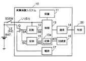
- FIG. 2 is a block diagram showing a first configuration example of the occupant protection system
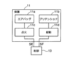
- FIG. 3 is a block diagram illustrating a configuration example of an occupant protection device
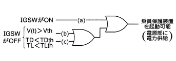
- FIG. 4 is a schematic diagram showing conditions for enabling the occupant protection device to be activated
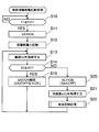
- FIG. 5 is a flowchart showing an example of a procedure for occupant protection device activation processing.
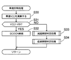
- FIG. 6 is a flowchart showing a procedure example of the vehicle speed reflection process.
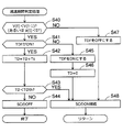
- FIG. 7 is a flowchart showing a procedure example of the deceleration period determination process.
- FIG. 1 is a schematic diagram showing a configuration example of a vehicle.
- FIG. 2 is a block diagram showing a first configuration example of the occupant protection system
- FIG. 3 is a block diagram illustrating a configuration example of an occupant protection device
- FIG. 4 is a schematic diagram showing conditions for enabling the occupant protection device to be activated
- FIG. 8 is a flowchart showing a procedure example of the low speed period determination process.
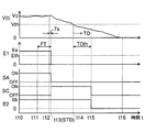
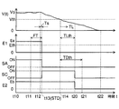
- FIG. 9 is a time chart showing a first example that enables activation of the occupant protection device
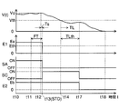
- FIG. 10 is a time chart showing a second example enabling the activation of the occupant protection device
- FIG. 11 is a time chart showing a third example enabling the activation of the passenger protection device
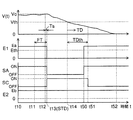
- FIG. 12 is a time chart showing a fourth example enabling the activation of the occupant protection device
- FIG. 13 is a time chart showing a fifth example enabling the activation of the occupant protection device
- FIG. 14 is a time chart showing a sixth example that enables activation of the occupant protection device
- FIG. 15 is a block diagram partially showing a second configuration example of the occupant protection system
- FIG. 16 is a schematic diagram illustrating an example in which the second power supply line has a redundant configuration.
- connecting means electrically connecting.
- FIG. 1 illustrates elements necessary to describe the present disclosure, and not all actual elements are illustrated. When referring to directions such as up, down, left and right, the description in the drawings is used as a reference. In each figure, the same elements are denoted by the same reference numerals.
- vehicle speed is simply referred to as “vehicle speed”.
- a parameter “(t)” is attached to a value that changes over time.
- the “running” of the vehicle includes a short-term pause according to signals, signs, and the like. In this embodiment, positive logic is applied as ON / OFF.
- a vehicle C shown in FIG. 1 is a four-wheeled vehicle having a battery BAT, an ignition switch IGSW, an airbag 11a, a seat belt pretensioner 11b, an acceleration sensor 16, and the like.
- the power engine of the vehicle C does not matter.
- the battery BAT is an electric power source that supplies electric power necessary for traveling the vehicle C, operating the occupant protection device 11, and the like.
- the battery BAT is arbitrary as long as it is a power source capable of supplying power, and for example, a secondary battery, a fuel cell, a solar cell, or the like is applicable.
- the secondary battery corresponds to, for example, a lithium ion battery, a chemical battery such as a lead storage battery or a nickel cadmium storage battery.
- the ignition switch IGSW is a switch for switching whether to supply power from the battery BAT, and does not matter the installation position in the vehicle C.
- the position illustrated with a solid line may be sufficient as the position illustrated with a dashed-two dotted line.
- the battery BAT supplies the vehicle to the occupant protection system 10 (specifically, the power supply unit 17) via the ignition switch IGSW as shown in FIG. It supplies also to the other apparatus provided.
- the airbag 11a is provided around a seat (for example, a driver seat or a passenger seat) and operates in an emergency to protect an occupant.
- the seat belt pretensioner 11b is connected to a seat belt (not shown) and operates in an emergency to protect the occupant.
- One or more airbags 11a and seat belt pretensioners 11b may be installed.
- the acceleration sensor 16 detects the acceleration a of the vehicle C.
- the occupant protection system 10 shown in FIG. 2 includes an occupant protection device 11, an activation unit 12, a control unit 13, a communication unit 14, a vehicle speed reflection unit 15, an acceleration sensor 16, a power supply unit 17, a switch unit Q, a first power line L1, A second power supply line L2 and the like are included.
- the elements other than the occupant protection device 11 may be arranged or configured arbitrarily, and may be provided independently of each other, or a plurality of elements may be integrated. Since there is no need to provide a power storage unit, it is possible to ensure miniaturization and weight reduction.
- a configuration example of the passenger protection device 11 will be described with reference to FIG. 3 includes an airbag 11a, a seat belt pretensioner 11b, an ignition unit 11c, a drive unit 11d, and the like.
- the airbag 11a and the seat belt pretensioner 11b are members that protect the passengers of the vehicle C.
- the ignition unit 11c includes, for example, a squib that performs ignition.
- the seat belt pretensioner 11b operates the seat belt (including expansion and contraction and holding) to protect the occupant.
- the drive unit 11d includes, for example, a motor and a squib.
- the first power supply line L1 and the second power supply line L2 are both conductive lines and cables for sending the power of the battery BAT.
- the starting unit 12, the control unit 13, the communication unit 14, and the vehicle speed reflecting unit 15 may all have a software configuration or a hardware configuration.
- the software configuration is a configuration in which the function of each unit is realized by the CPU executing a program.
- the hardware configuration is a configuration in which functions of each unit are realized by hardware logic including an electronic circuit and a logic circuit.
- the power supply unit 17 converts the power supplied from the battery BAT and outputs it to the occupant protection device 11, the starter unit 12, the control unit 13, the communication unit 14, the vehicle speed reflecting unit 15, the acceleration sensor 16, and the like.
- the control unit 13 controls the entire occupant protection system 10.
- the control unit 13 includes control for monitoring the supply voltage E1 supplied from the battery BAT to the first power supply line L1 via the ignition switch IGSW.
- the control unit 13 includes control for transmitting the control signal SB to the starting unit 12 and transmitting the control signal SD to the vehicle speed reflecting unit 15.
- the control unit 13 calculates the vehicle speed V (that is, the speed of the vehicle C) based on the acceleration a transmitted from the acceleration sensor 16, or activates the occupant protection device 11 when the acceleration a changes to an acceleration threshold value ath or more due to a collision or the like. Includes control to activate.
- the control unit 13 includes control for transmitting and receiving information to and from the external device 20 via the communication unit 14. Transmission and reception may be wired or wireless.
- the external device 20 that is communicably connected to the occupant protection system 10 corresponds to, for example, one or more ECUs (Electronic Control Units), one or more computers, and may include a communication network provided in the vehicle C.
- the switch part Q is interposed between the battery BAT and the power supply part 17.
- the switch unit Q When the switch unit Q is in a conductive state (for example, an on state), the power of the battery BAT is supplied to the power source unit 17. On the other hand, when the switch unit Q is in a non-conduction state (for example, an off state), the power of the battery BAT is not supplied to the power source unit 17.
- a transistor is applied as the switch unit Q.
- the type of the transistor is arbitrary, but, for example, FET or IGBT is applicable.
- the starting unit 12 transmits a control signal SA to the switch unit Q (for example, a control terminal such as a gate terminal or a base terminal), and switches the switch unit Q to either the conductive state or the non-conductive state.
- the vehicle speed reflecting unit 15 transmits the control signal SC to the switch unit Q, and switches the switch unit Q to either the conductive state or the non-conductive state.
- the control signal SA and the control signal SC are logically summed and transmitted to the switch unit Q.
- the control unit 13 performs necessary control based on whether or not a predetermined condition is satisfied.
- the predetermined condition may be arbitrarily set, and includes, for example, a vehicle speed condition, a speed non-acquisition condition, a deceleration period condition, a low speed period condition, and the like.
- the vehicle speed condition is a condition for determining whether or not the vehicle speed V (t) is equal to or higher than the speed threshold value Vth (see also S31 in FIG. 6 described later).
- the speed non-acquisition condition is a condition in which the current vehicle speed Vo cannot be acquired from the external device 20 via the communication unit 14. Specifically, the case where the power supply is not received from the battery BAT and the supply voltage E1 is less than the voltage threshold Eth (E1 ⁇ Eth) and the case where the vehicle speed Vo is not transmitted from the external device 20 are applicable.
- the deceleration period condition is a condition for determining whether or not the deceleration period TD is shorter than the allowable deceleration period TDth (see also S43 in FIG. 7 described later).
- the deceleration period TD is a period in which the vehicle speed V is equal to or lower than the speed threshold Vth and continuously decreases.
- the low speed period condition is a condition for determining whether or not the low speed period TL is shorter than the low speed allowable period TLth (see also S53 in FIG. 8 described later).
- the low speed period TL is a period during which the vehicle speed V (t) continues to be equal to or lower than the speed threshold Vth.
- Any length may be set for the deceleration allowable period TDth and the low speed allowable period TLth described above, for example, 30 [sec] or 2 [min].
- the control unit 13 transmits an ON control signal SB to the starting unit 12.
- the activation unit 12 switches the switch unit Q to the conductive state or continues with the ON control signal SA.
- the normal state also referred to as a normal state
- the power of the battery BAT is supplied to the power supply unit 17, so that the occupant protection device 11 can be activated.
- the abnormal state corresponds to, for example, the ignition switch IGSW being turned off, a failure (for example, disconnection or short circuit) in the first power supply line L1, or an abnormality in the battery BAT itself.
- a state in which the supply of electric power is cut off from the battery BAT via the ignition switch IGSW during traveling of the vehicle C is applicable.
- the activation unit 12 that has received the OFF control signal SB or no longer receives the ON control signal SB causes the switch unit Q to be in a non-conductive state by the OFF control signal SA. If the switch part Q becomes a non-conduction state in an abnormal state, the power of the battery BAT is not supplied to the power supply part 17 and the occupant protection device 11 cannot be activated.
- the control unit 13 performs control so that the occupant protection device 11 can be activated if the vehicle speed condition, the speed non-acquisition condition, the deceleration period condition, and the low speed period condition are satisfied.
- the time when the supply voltage E1 becomes less than the voltage threshold Eth is set as a reference time STD.
- a later time is applied between the reference time STD and the start of the deceleration period TD.
- the start time of the low speed period TL included in the low speed period condition is a later time of the reference time STD and the start time of the low speed period TL.
- control unit 13 transmits an ON control signal SD to the vehicle speed reflecting unit 15 if any one of the vehicle speed condition, the speed non-acquisition condition, the deceleration period condition, and the low speed period condition is satisfied.
- the vehicle speed reflecting unit 15 that has received the ON control signal SD switches the switch unit Q to the conductive state or continues by the ON control signal SC.
- the control unit 13 sends an OFF control signal SD to the vehicle speed reflection unit 15. It is transmitted or the ON control signal SD is not transmitted.
- the vehicle speed reflecting unit 15 that has received the OFF control signal SD or no longer receives the ON control signal SD makes the switch unit Q non-conductive by the OFF control signal SC.
- the control unit 13 described above performs control to maintain a state where the occupant protection device 11 can be activated as shown in the logic diagram of FIG. That is, the switch unit Q is turned on, and the power of the battery BAT is supplied to the power source unit 17.
- Case (a) corresponds to a state where the ignition switch IGSW is ON and the supply voltage E1 is equal to or higher than the voltage threshold Eth.
- Case (b) and case (c) are based on the assumption that the ignition switch IGSW is OFF (or the first power supply line L1 is disconnected, etc.).
- Case (b) corresponds to a state where the current vehicle speed V (t) exceeds the speed threshold Vth.
- Case (c) is a state in which the current vehicle speed V (t) is not more than the speed threshold value Vth, and the deceleration period condition and the low speed period condition are satisfied. That is, the deceleration period TD is shorter than the allowable deceleration period TDth (TD ⁇ TDth), or the low speed period TL is shorter than the allowable low speed period TLth (TL ⁇ TLth).
- control executed by the control unit 13 will be described with reference to flowcharts shown in FIGS.
- the occupant protection device activation process shown in FIG. 5 is executed on the assumption that the ignition switch IGSW is turned from OFF to ON in a stopped vehicle.
- the supply voltage E1 of the first power supply line L1 is equal to or higher than the voltage threshold Eth (S10). If the supply voltage E1 is lower than the voltage threshold Eth (E1 ⁇ Eth; NO in S10), the ignition switch IGSW is OFF and the vehicle C does not travel, so it waits.
- the control unit 13 transmits the ON control signal SB to the activation unit 12, and the activation unit 12 transmits the ON control signal SA to the switch unit Q to switch to the conductive state (S11).
- the switch part Q becomes conductive, power is supplied from the battery BAT to the power supply part 17, and the occupant protection device 11 can be activated (S12).
- the control unit 13 acquires the current vehicle speed Vo from the external device 20 via the communication unit 14 (step S13). It does not matter how the vehicle speed Vo is acquired.
- the vehicle speed Vo may be acquired within a predetermined period FT from a reference time STD described later, and is preferably immediately before the reference time STD.
- the length of the predetermined period FT may be arbitrarily set, and an average value or the like may be used when a plurality of vehicle speeds Vo are acquired within the predetermined period FT.
- the acceleration a transmitted from the acceleration sensor 16 is calculated to obtain the calculated vehicle speed Vo.
- the control unit 13 continues to transmit the ON control signal SB to the starting unit 12. Therefore, the activation unit 12 transmits the ON control signal SA to the switch unit Q and continues the conduction state (S15). Since the switch part Q continues to be in a conductive state, power is continuously supplied from the battery BAT to the power supply part 17 and the state in which the occupant protection device 11 can be started continues.
- the control unit 13 determines that an abnormal state has occurred.
- the occurrence time of the abnormal state is set as a reference time STD. Since the vehicle speed Vo cannot be acquired from the external device 20, the speed non-acquisition condition is satisfied.
- the control unit 13 transmits the ON control signal SD to the vehicle speed reflecting unit 15, and the vehicle speed reflecting unit 15 transmits the ON control signal SC to the switch unit Q and continues the conduction state (S20).
- the OFF control signal SB may be transmitted to the activation unit 12, and the activation unit 12 may transmit the OFF control signal SA to the switch unit Q so as to be in a non-conductive state. Since the conduction state of the switch unit Q is continued by the vehicle speed reflecting unit 15, power is continuously supplied from the battery BAT to the power source unit 17, and the state where the occupant protection device 11 can be started is also continued.
- the control unit 13 acquires the acceleration a (t) from the acceleration sensor 16 in order to estimate the current vehicle C ( S21), the vehicle speed reflecting process shown in FIG. 6 is executed (S22).
- the current vehicle speed V (t) is estimated by calculation using the acceleration a (t) acquired in S21 (S30).
- the vehicle speed V (t) corresponds to the calculated value.
- the estimated vehicle speed V (t) is recorded in the recording medium 13a and used as the previous vehicle speed V (t-1) in estimating the next vehicle speed V (t).
- An arithmetic expression for obtaining the vehicle speed V (t) is the following expression M1, and a vehicle speed V (0) that is an initial value of the vehicle speed V (t) is an expression M2.
- Formula M1 adds the value obtained by integrating the acceleration a (t) in the period from time (t-1) to time t to the previously calculated vehicle speed V (t-1), so that the current vehicle speed V ( t) can be determined.
- a period from time (t ⁇ 1) to time t corresponds to a “sampling period”, and an arbitrary length (for example, 10 [msec] or 100 [msec]) may be set.
- Expression M2 sets the vehicle speed Vo acquired in step S13 of FIG. 5 as the vehicle speed V (0). By setting in this way, the accuracy of the vehicle speed V (t) after the occurrence of an abnormal state is increased.
- the vehicle speed condition is a condition that, for example, the vehicle speed V (t) obtained in S30 is larger than the speed threshold value Vth.
- the speed threshold Vth may be arbitrarily set, and corresponds to 10 [Km / h], 16 [Km / h], or the like, for example. If the vehicle speed V (t) is larger than the speed threshold value Vth (V (t)> Vth; YES in S31), the control unit 13 continuously transmits the ON control signal SD to the vehicle speed reflection unit 15, and the vehicle speed.
- the reflecting unit 15 continuously transmits the ON control signal SC to the switch unit Q and continues the conduction state (S32). Therefore, power is continuously supplied from the battery BAT to the power supply unit 17, and the state in which the occupant protection device 11 can be started continues. Thereafter, the vehicle speed reflection process is returned, and the process returns to S13 shown in FIG.
- the deceleration period determination process shown in FIG. 7 S33
- the low speed period determination process shown in FIG. Is executed S34.
- the deceleration period determination process and the low speed period determination process are not limited to the order shown in FIG. 6, and may be executed in any order or in parallel. Thereafter, the vehicle speed reflection process is returned, and the process returns to S13 of the occupant protection device activation process shown in FIG.
- an example of the deceleration period determination process and the low speed period determination process will be described.
- the process branches depending on whether or not the vehicle C is decelerating (S40). For example, the determination is made based on whether or not the current vehicle speed V (t) obtained in S30 of FIG. 6 is smaller than the previous vehicle speed V (t-1). Note that, as shown in parentheses in S40, the determination may be made based on whether or not the acceleration a (t) acquired in S21 in FIG. 5 is a negative value.
- the process branches depending on the state of the deceleration period flag TDF (S41).
- the deceleration period flag TDF is a flag indicating whether or not the vehicle speed V continuously decreases.
- the deceleration period flag TDF is ON as long as the vehicle C continues to decelerate, and is OFF when the vehicle C is not decelerating (that is, acceleration or constant speed).
- the deceleration period TD is increased (S42).
- the deceleration period TD on the left side is the deceleration period TD that is required this time.
- the deceleration period TD on the right side is a value obtained last time and recorded on the recording medium 13a.
- the sampling time Ts on the right side is the period from time (t-1) to time t described above. That is, as long as the deceleration period flag TDF remains ON, the deceleration period TD increases by the sampling time Ts.
- the deceleration period condition is, for example, a condition that the deceleration period TD is shorter than the allowable deceleration period TDth.
- the deceleration period flag TDF is turned OFF (S47). Since the vehicle C is not decelerating, the above-described S48 is executed in order to continue supplying power from the battery BAT to the power supply unit 17 and continue the state in which the occupant protection device 11 can be activated. Thereafter, the deceleration period determination process is returned to return to the vehicle speed reflection process of FIG.
- the deceleration period flag TDF is OFF in S41 (NO)
- the vehicle C starts to decelerate, so the deceleration period flag TDF is turned ON (S45), and the deceleration period TD is initialized to 0 (S46).
- the electric power is continuously supplied from the battery BAT to the power source unit 17 and the above-described S48 is executed in order to continue the state where the occupant protection device 11 can be activated. Thereafter, the deceleration period determination process is returned to return to the vehicle speed reflection process of FIG.
- the control unit 13 transmits the OFF control signal SD to the vehicle speed reflection unit 15, and the vehicle speed reflection unit 15 An OFF control signal SC is transmitted to the switch part Q to make it non-conductive (S44). Therefore, power is not supplied from the battery BAT to the power supply unit 17, and the function of the entire occupant protection system 10 is stopped.
- the time when the occupant protection device 11 can be activated until the deceleration period TD passes the deceleration allowable period TDth power consumption of the battery BAT can be suppressed.
- the process branches depending on whether or not the vehicle C is traveling at a vehicle speed V (t) equal to or lower than the speed threshold Vth (S50). For example, the determination is made based on whether or not the current vehicle speed V (t) obtained in S30 of FIG.
- the low speed period flag TLF is a flag indicating whether or not the vehicle speed V is continuously running at a low speed.
- the low speed period flag TLF is ON as long as the vehicle C is traveling at a low speed equal to or less than the speed threshold Vth, and is OFF when the vehicle C travels exceeding the speed threshold Vth.
- the low speed period TL is increased (S52).
- the low speed period TL on the left side is the low speed period TL to be obtained this time.
- the low speed period TL on the right side is a value obtained last time and recorded on the recording medium 13a.
- the sampling time Ts on the right side is the period from time (t-1) to time t described above. That is, as long as the low speed period flag TLF remains ON, the low speed period TL increases by the sampling time Ts.
- the process branches depending on whether the low speed period condition is satisfied (S53).
- the low speed period condition is, for example, a condition that the low speed period TL is shorter than the low speed allowable period TLth.
- the low speed allowable period TLth may be set to an arbitrary length in the same manner as the deceleration allowable period TDth.
- the low speed period flag TLF is turned off (S57). Since the vehicle C is not traveling at a low speed, the power supply unit 17 is continuously supplied with power from the battery BAT, and the above-described S58 is executed in order to continue the state where the occupant protection device 11 can be activated. Thereafter, the low speed period determination process is returned to return to the vehicle speed reflection process of FIG.
- the low speed period flag TLF is OFF in S51 (NO)
- the vehicle C starts running at a low speed
- the low speed period flag TLF is turned ON (S55)
- the low speed period TL is initialized to 0 ( S56).
- the time initialized in S56 is the start of the low speed period TL.
- the above-described S58 is executed in order to continue supplying power from the battery BAT to the power supply unit 17 and to keep the occupant protection device 11 from being activated. Thereafter, the low speed period determination process is returned to return to the vehicle speed reflection process of FIG.
- the control unit 13 transmits the OFF control signal SD to the vehicle speed reflection unit 15, and the vehicle speed reflection unit 15 An OFF control signal SC is transmitted to the switch part Q to make it non-conductive (S54). Therefore, power is not supplied from the battery BAT to the power supply unit 17, and the function of the entire passenger protection system 10 is stopped.
- the power consumption of the battery BAT can be suppressed.
- FIG. 9 to FIG. 9 show control examples when the above-described occupant protection device activation processing (FIG. 5), vehicle speed reflection processing (FIG. 6), deceleration period determination processing (FIG. 7), and low speed period determination processing (FIG. 8) are executed. This will be described with reference to FIG.
- the first example shown in FIG. 9 is an example in which the occupant protection device 11 can be activated while the vehicle speed condition and the deceleration period condition are satisfied.
- the relationship between the allowable deceleration period TDth and the allowable low speed period TLth is TDth ⁇ TLth.
- the control unit 13 transmits the ON control signal SB to the activation unit 12, and the activation unit 12 sets the switch unit Q to the conductive state by the ON control signal SA (S15 in FIG. 5). Since the voltage is lower than the voltage threshold Eth after time t13 (0 [V] in FIG. 9), the control unit 13 transmits the ON control signal SD to the vehicle speed reflecting unit 15, and the vehicle speed reflecting unit 15 controls the ON.
- the switch part Q is turned on by the signal SC (S20 in FIG. 5).
- the switch unit Q remains conductive after time t13, and the power supply unit 17 is supplied with power of the supply voltage E2 (voltage Eb in FIG. 9) from the battery BAT via the second power supply line L2. Continue to be able to start.
- the control unit 13 can acquire the vehicle speed Vo from the external device 20 via the communication unit 14.
- the current vehicle speed V is obtained using the vehicle speed Vo acquired in the predetermined period FT from the time t11 to the time t13 and recorded on the recording medium 13a, and the acceleration a (t) acquired from the acceleration sensor 16. (t) is estimated (S30 in FIG. 6). Since the vehicle speed V (t) becomes equal to or less than the speed threshold Vth at time t14, the deceleration period TD is counted starting from time t14 (S42 in FIG. 7), and the low speed period TL is counted (S52 in FIG. 8). .
- the deceleration period TD becomes equal to or greater than the allowable deceleration period TDth (S43 in FIG. 7).
- the low speed period TL is within the low speed allowable period TLth. Since the deceleration period TD is equal to or longer than the allowable deceleration period TDth, the control unit 13 transmits the OFF control signal SD to the vehicle speed reflecting unit 15, and the vehicle speed reflecting unit 15 is in the non-conducting state of the switch unit Q by the OFF control signal SC. (S44 in FIG. 7).
- the occupant protection device 11 is continuously activated, and the function of the entire occupant protection system 10 is stopped at the time t15. For example, even if the vehicle C exists on an uphill and temporarily decelerates, and then the vehicle C starts to descend, it is estimated that the vehicle C tends to stop by continuously decelerating. Can do. The vehicle C stopped traveling at time t16 after time t15.
- the second example shown in FIG. 10 is an example in which the occupant protection device 11 can be activated while the vehicle speed condition and the low speed period condition are satisfied.
- the relationship between the allowable deceleration period TDth and the allowable low speed period TLth is TDth ⁇ TLth.
- time t14 the description is omitted because it is the same as the first example shown in FIG. 9 described above.
- the vehicle speed V (t) After time t14, the vehicle speed V (t) remains below the speed threshold Vth, and at time t17, the low speed period TL becomes equal to or higher than the low speed allowable period TLth (S53 in FIG. 8). However, since the vehicle speed V (t) may increase between time t14 and time t17, the deceleration period TD is within the allowable deceleration period TDth. Since the low speed period TL is equal to or longer than the low speed allowable period TLth, the control unit 13 transmits the OFF control signal SD to the vehicle speed reflecting unit 15, and the vehicle speed reflecting unit 15 is in the non-conducting state of the switch unit Q by the OFF control signal SC. (S54 in FIG. 8). Therefore, until the time t15, the occupant protection device 11 is continuously activated, and the function of the entire occupant protection system 10 is stopped at the time t15. The vehicle C stopped traveling at time t18 after time t17.
- the third example shown in FIG. 11 is an example in which the occupant protection device 11 can be activated while the vehicle speed condition and the low speed period condition are satisfied.
- the relationship between the allowable deceleration period TDth and the allowable low speed period TLth is TDth> TLth.
- time t14 the description is omitted because it is the same as the first example shown in FIG. 9 and the second example shown in FIG.
- the vehicle speed V (t) continues to be equal to or lower than the speed threshold Vth, and at time t20, the low speed period TL becomes equal to or higher than the low speed allowable period TLth (S53 in FIG. 8).
- the deceleration period TD is within the allowable deceleration period TDth from time t14 to time t21. Since the low speed period TL is equal to or longer than the low speed allowable period TLth, the control unit 13 transmits the OFF control signal SD to the vehicle speed reflecting unit 15, and the vehicle speed reflecting unit 15 is in the non-conducting state of the switch unit Q by the OFF control signal SC. (S54 in FIG. 8). Therefore, until the time t20, the occupant protection device 11 is continuously activated, and the function of the entire occupant protection system 10 is stopped at the time t20. The vehicle C stopped traveling at time t22 after time t20.
- the fourth example shown in FIG. 12 is an example in which the occupant protection device 11 can be activated while the vehicle speed condition and the deceleration period condition are satisfied.
- the relationship between the allowable deceleration period TDth and the allowable low speed period TLth is TDth ⁇ TLth as in the first example.
- the difference from the first example is that the speed threshold Vth is set lower than in the first example. Until time t13, the description is omitted because it is the same as the first example shown in FIG. 9 and the second example shown in FIG.
- the deceleration period TD is counted starting from time t30 (S42 in FIG. 7), and the low speed period TL is counted (FIG. 8 S52).
- the vehicle speed V (t) continues to decelerate, and at time t32, the deceleration period TD becomes equal to or greater than the allowable deceleration period TDth (S43 in FIG. 7).
- the low speed period TL is within the low speed allowable period TLth. Since the deceleration period TD is equal to or longer than the allowable deceleration period TDth, the control unit 13 transmits the OFF control signal SD to the vehicle speed reflecting unit 15, and the vehicle speed reflecting unit 15 is in the non-conducting state of the switch unit Q by the OFF control signal SC. (S44 in FIG. 7). Therefore, until the time t32, the occupant protection device 11 is continuously activated, and the function of the entire occupant protection system 10 is stopped at the time t32. The vehicle C stopped traveling at time t31 before time t32.
- the fifth example shown in FIG. 13 is an example in which the occupant protection device 11 can be activated while the vehicle speed condition and the low speed period condition are satisfied.
- the difference from the first example is that the supply voltage E1 becomes less than the voltage threshold Eth after the vehicle speed V (t) becomes equal to or less than the speed threshold Vth.
- the supply voltage E1 of the first power line L1 is the voltage Ea that exceeds the voltage threshold Eth until time t44.
- the control unit 13 transmits the ON control signal SB to the activation unit 12, and the activation unit 12 sets the switch unit Q to the conductive state by the ON control signal SA (S15 in FIG. 5). Since the voltage is lower than the voltage threshold Eth after time t44 (0 [V] in FIG. 13), the control unit 13 transmits the ON control signal SD to the vehicle speed reflecting unit 15, and the vehicle speed reflecting unit 15 is controlled to be ON.
- the switch part Q is turned on by the signal SC (S20 in FIG. 5).
- the switch unit Q remains conductive after time t44, and the power source unit 17 is supplied with power of the supply voltage E2 (voltage Eb in FIG. 13) from the battery BAT via the second power source line L2. Continue to be able to start.
- the control unit 13 can acquire the vehicle speed Vo from the external device 20 via the communication unit 14.
- the current vehicle speed V is obtained using the vehicle speed Vo acquired in the predetermined period FT from time t41 to time t44 and recorded on the recording medium 13a and the acceleration a (t) acquired from the acceleration sensor 16. (t) is estimated (S30 in FIG. 6).
- the vehicle speed V (t) becomes equal to or less than the speed threshold Vth. Therefore, the deceleration period TD is counted starting from time t44 (S42 in FIG. 7), and the low speed period TL is counted. (S52 in FIG. 8).
- the vehicle speed V (t) continues to be equal to or lower than the speed threshold Vth, and at time t45, the low speed period TL becomes equal to or higher than the low speed allowable period TLth (S53 in FIG. 8).
- the deceleration period TD is within the allowable deceleration period TDth.
- the control unit 13 transmits the OFF control signal SD to the vehicle speed reflecting unit 15, and the vehicle speed reflecting unit 15 is in the non-conducting state of the switch unit Q by the OFF control signal SC. (S54 in FIG. 8). Therefore, until the time t45, the occupant protection device 11 is continuously activated, and the function of the entire occupant protection system 10 is stopped at the time t45.
- the vehicle C stopped traveling at time t46 after time t45.
- the deceleration period TD first becomes equal to or longer than the allowable deceleration period TDth (S43 in FIG. 7).
- the control unit 13 transmits the OFF control signal SD to the vehicle speed reflecting unit 15, and the vehicle speed reflecting unit 15 makes the switch unit Q non-conductive by the OFF control signal SC (S44 in FIG. 7).
- the sixth example shown in FIG. 14 is an example in which the ignition switch IGSW is turned on while the deceleration period condition is satisfied, and the occupant protection device 11 can be activated.
- the relationship between the allowable deceleration period TDth and the allowable low speed period TLth is TDth ⁇ TLth.
- time t14 the description is omitted because it is the same as the first example shown in FIG. 9 described above.
- the vehicle speed V (t) continues to decelerate, and at time t51, the deceleration period TD becomes equal to or greater than the allowable deceleration period TDth (S43 in FIG. 7).
- the low speed period TL is within the low speed allowable period TLth.
- the ignition switch IGSW is turned on, and the supply voltage E1 of the first power supply line L1 returns to the voltage Ea exceeding the voltage threshold Eth. Therefore, the ON control signal SB is transmitted to the activation unit 12, and the activation unit 12 sets the switch unit Q to the conductive state by the ON control signal SA (S15 in FIG. 5).
- the vehicle C stops at time t52 after time t51, the occupant protection device 11 is continued to be activated regardless of whether or not the vehicle C is traveling.
- the occupant protection system 10 is configured to include the activation unit 12 and the vehicle speed reflection unit 15 separately (see FIG. 2).
- the switch control part 18 which integrated the starting part 12 and the vehicle speed reflection part 15.
- the switch control unit 18 has both the function of the activation unit 12 and the function of the vehicle speed reflection unit 15. Since there is only a difference between a separate configuration and an integrated configuration, the same operational effects as in the embodiment can be obtained.
- the battery BAT and the occupant protection system 10 are connected by a single second power line L2 (see FIG. 2).
- a redundant configuration in which the battery BAT and the occupant protection system 10 are connected by a plurality of second power supply lines L2.
- FIG. 16 shows second power supply lines L2a and L2b corresponding to the second power supply line L2.
- the second power supply line L2a and the second power supply line L2b are connected in parallel between the battery BAT and the occupant protection system 10.
- the combined resistance value between the battery BAT and the occupant protection system 10 can be reduced, and power loss due to the power line can be suppressed.
- a redundant configuration in which three or more second power supply lines L2 are connected in parallel may be employed. About the other, the effect similar to embodiment is obtained.
- a transistor is used as the switch unit Q (see FIG. 2).
- a relay may be used as the switch unit Q.
- the relay may be a magnetic type or a semiconductor type. Since power can be supplied from the battery BAT to the power supply unit 17, the same effects as those of the embodiment can be obtained.
- a four-wheeled vehicle is applied as the vehicle C (see FIG. 1).
- the vehicle C may be applied to a two-wheeled vehicle. That is, the present invention can be applied to a vehicle including the occupant protection device 11 regardless of the number of wheels or the power engine. Since only the type of the vehicle C is different, the same effect as the embodiment can be obtained.
- the “vehicle” may be any number of wheels or power engine.
- any device may be applied as long as it can protect the occupant, and examples thereof include an airbag and a seat belt pretensioner.
- the “switch unit” may be any element or component that can be switched between a conductive state and a non-conductive state by an activation unit, a vehicle speed reflecting unit, or the like. For example, a transistor, a relay, etc. correspond.
- the “ignition switch” is arbitrary as long as it is a switch for switching whether or not power is supplied from the battery for traveling of the vehicle or the like, regardless of whether or not a mechanical key is used.
- the “battery” is arbitrary regardless of the type as long as it can supply electric power for operating the occupant protection device.
- “Activation” of the occupant protection device means a state in which the occupant protection device can be activated when acceleration exceeding an allowable value due to a collision or the like is detected.
- each step is expressed as S10, for example. Further, each step can be divided into a plurality of sub-steps, while a plurality of steps can be combined into one step.
Landscapes
- Engineering & Computer Science (AREA)
- Mechanical Engineering (AREA)
- Electric Propulsion And Braking For Vehicles (AREA)
Abstract
乗員保護システムは、乗員保護装置(11)と、加速度センサ(16)と、制御部(13)と、スイッチ部(Q)と、電源部とを含む。乗員保護システムは、バッテリからイグニッションスイッチ(IGSW)を介して第1電源線(L1)に供給される供給電圧(E1)が電圧閾値以上であるか否かにより、スイッチ部を導通状態または非導通状態のいずれかに切り替える起動部(12)と、イグニッションスイッチを介さず、かつ、スイッチ部を介してバッテリと電源部との間を電気的に接続する第2電源線(L2)と、加速度センサで検出される加速度を用いて演算した演算値により、スイッチ部を導通状態または非導通状態のいずれかに切り替える車速反映部(15)とを有する。
Description
本出願は、2015年6月25日に出願された日本国特許出願2015-127257号に基づくものであり、ここにその記載内容を参照により援用する。
本開示は、乗員保護装置,加速度センサ,制御部,スイッチ部および電源部を含む乗員保護システムに関する。
不測の障害によってバッテリ等からの電力供給が断たれた場合であっても稼働可能にするための車両用乗員保護システムに関する技術の一例が開示されている(例えば特許文献1を参照)。この車両用乗員保護システムは、安全装置と、蓄電部と、第1分岐ライン上における加速度センサユニットの手前とを接続するバイパスラインと、バイパスラインを開閉するスイッチング部と、電源ラインの電圧を検出する電源電圧モニタ部と、電源電圧モニタ部の検出した電圧が所定の閾値以下であった場合にスイッチング部を閉じるスイッチ制御部とを有する。
特許文献1に記載された技術では、蓄電部を必要とする。この蓄電部は、車両が走行中の衝突判定及び安全装置(乗員保護装置に相当する)を起動させるための電源として使用するため、大容量にせざるを得ない。したがって、蓄電部は大型化し、乗員保護システムの小型化や軽量化の妨げるおそれがある。
蓄電部を設けない場合は、バッテリからイグニッションスイッチを介して電力の供給が断たれると、外部装置から車両に関する情報(例えば車両の速度等)を取得できなくなる。そのため、車両が走行中であるのか停止中であるのかを判別できず、乗員保護装置の起動を継続すべきであるか否かの判断ができないおそれがある。
本開示は、小型化や軽量化を確保するとともに、バッテリからイグニッションスイッチを介して電力の供給が断たれても乗員保護装置の起動を継続できる乗員保護システムを提供することを目的とする。
本開示の一例による乗員保護システムは、車両の乗員を保護する乗員保護装置と、車両の加速度を検出する加速度センサと、加速度センサで検出される加速度に基づいて乗員保護装置の作動を制御する制御部と、バッテリと電源部との間に介在され、導通状態と非導通状態とを切り替え可能なスイッチ部と、バッテリからスイッチ部を介して供給される電力を変換し、少なくとも乗員保護装置,加速度センサおよび制御部に出力する電源部とを含む。乗員保護システムは、起動部と、第2電源線と、車速反映部とを備える。起動部は、バッテリからイグニッションスイッチを介して第1電源線に供給される供給電圧が電圧閾値以上であるか否かにより、スイッチ部を導通状態または非導通状態のいずれかに切り替える。第2電源線は、イグニッションスイッチを介さず、かつ、スイッチ部を介してバッテリと電源部との間を電気的に接続する。車速反映部は、加速度センサで検出される加速度を用いて演算した演算値により、スイッチ部を導通状態または非導通状態のいずれかに切り替える。
本開示の乗員保護システムによれば、異常状態ではバッテリからイグニッションスイッチを介して電力の供給が断たれ、第1電源線に供給される供給電圧が電圧閾値未満になる。そのため、制御部および車速反映部の制御によってスイッチ部が導通状態に切り替えられる。よって、バッテリから供給される電力は電源部を介して乗員保護装置,加速度センサおよび制御部などに出力される。蓄電部を設ける必要がないので小型化や軽量化を確保することができる。また、バッテリからイグニッションスイッチを介して電力の供給が断たれた場合でも、スイッチ部が導通状態に切り替えられるので、乗員保護装置の起動を継続できる。
通常状態は、バッテリからイグニッションスイッチを介して電力が供給され、第1電源線に供給される供給電圧が電圧閾値以上になる。そのため、制御部および起動部の制御によってスイッチ部が導通状態に切り替えられる。よって、バッテリから供給される電力は電源部を介して乗員保護装置,加速度センサおよび制御部などに出力される。そのため、通常状態でも確実に乗員保護装置の起動を継続できる。
本開示についての上記および他の目的、特徴や利点は、添付図面を参照した下記詳細な説明から、より明確になる。添付図面において、
図1は、車両の構成例を示す模式図であり、
図2は、乗員保護システムの第1構成例を示すブロック図であり、
図3は、乗員保護装置の構成例を示すブロック図であり、
図4は、乗員保護装置を起動可能にする条件を示す模式図であり、
図5は、乗員保護装置起動処理の手続き例を示すフローチャート図であり、
図6は、車速反映処理の手続き例を示すフローチャート図であり、
図7は、減速期間判定処理の手続き例を示すフローチャート図であり、
図8は、低速期間判定処理の手続き例を示すフローチャート図であり、
図9は、乗員保護装置の起動を可能にする第1例を示すタイムチャート図であり、
図10は、乗員保護装置の起動を可能にする第2例を示すタイムチャート図であり、
図11は、乗員保護装置の起動を可能にする第3例を示すタイムチャート図であり、
図12は、乗員保護装置の起動を可能にする第4例を示すタイムチャート図であり、
図13は、乗員保護装置の起動を可能にする第5例を示すタイムチャート図であり、
図14は、乗員保護装置の起動を可能にする第6例を示すタイムチャート図であり、
図15は、乗員保護システムの第2構成例を部分的に示すブロック図であり、
図16は、第2電源線を冗長構成にする例を示す模式図である。
以下、本開示を実施するための形態について、図面に基づいて説明する。なお、特に明示しない限り、「接続する」という場合には電気的に接続することを意味する。各図は、本開示を説明するために必要な要素を図示し、実際の全要素を図示しているとは限らない。上下左右等の方向を言う場合には、図面の記載を基準とする。各図において、同一の要素には同一の符号を付す。以下では、「車両の速度」を単に「車速」と呼ぶ。車速や加速度は、経時的に変化する値についてパラメータ「(t)」を付す。車両の「走行中」には、信号や標識等に従った短期間の一時停止を含む。本形態では、ON/OFFとして正論理を適用する。
図1に示す車両Cは、バッテリBAT,イグニッションスイッチIGSW,エアバッグ11a,シートベルトプリテンショナ11b,加速度センサ16などを有する四輪自動車である。車両Cの動力機関は問わない。バッテリBATは、車両Cの走行や、乗員保護装置11の作動などに必要な電力を供給する電力源である。このバッテリBATは電力を供給可能な電力源であれば任意であり、例えば二次電池,燃料電池,太陽電池などが該当する。二次電池は、例えばリチウムイオン電池や、鉛蓄電池やニッケルカドミウム蓄電池等の化学電池などが該当する。
イグニッションスイッチIGSWは、バッテリBATから電力を供給するか否かを切り替えるスイッチであり、車両C内の設置位置を問わない。例えば、実線で図示する位置でもよく、二点鎖線で図示する位置でもよい。本形態では、図2に示すようにバッテリBATからイグニッションスイッチIGSWを介して乗員保護システム10(具体的には電源部17)に供給する例を説明するが、外部装置20を含めて車両Cに設けられる他装置にも供給する。エアバッグ11aは、座席(例えば運転席や助手席等)の周囲に設けられて、非常時に作動して乗員を保護する。シートベルトプリテンショナ11bは、図示しないシートベルトに連結され、非常時に作動して乗員を保護する。エアバッグ11aやシートベルトプリテンショナ11bは、それぞれ一以上で任意の数を設置してよい。加速度センサ16は、車両Cの加速度aを検出する。
図2に示す乗員保護システム10は、乗員保護装置11,起動部12,制御部13,通信部14,車速反映部15,加速度センサ16,電源部17,スイッチ部Q,第1電源線L1,第2電源線L2などを有する。乗員保護装置11を除いた要素は、配置や構成等は任意であり、個々に独立して設けてもよく、複数の要素を一体化してもよい。蓄電部を設ける必要がないので、小型化や軽量化を確保することができる。
乗員保護装置11の構成例について、図3を参照しながら説明する。図3に示す乗員保護装置11は、エアバッグ11a,シートベルトプリテンショナ11b,点火部11c,駆動部11dなどを有する。エアバッグ11aとシートベルトプリテンショナ11bは、いずれも車両Cの乗員を保護する部材である。エアバッグ11aは、制御部13から点火部11cに制御信号SEが伝達されると展開して乗員を保護する。点火部11cには、例えば点火を行うスクイブ等を含む。シートベルトプリテンショナ11bは、制御部13から駆動部11dに制御信号SFが伝達されるとシートベルトを作動(伸縮や保持を含む)させて乗員を保護する。駆動部11dには、例えばモータやスクイブ等を含む。
図2に戻り、第1電源線L1と第2電源線L2は、いずれもバッテリBATの電力を送るための導電線やケーブル等である。起動部12,制御部13,通信部14,車速反映部15は、いずれもソフトウェア構成でもよく、ハードウェア構成でもよい。ソフトウェア構成は、CPUがプログラムを実行することで各部の機能を実現する構成である。ハードウェア構成は、電子回路や論理回路などを含むハードウェアロジックで各部の機能を実現する構成である。電源部17は、バッテリBATから供給される電力を変換して、乗員保護装置11,起動部12,制御部13,通信部14,車速反映部15,加速度センサ16などに出力する。
制御部13は、乗員保護システム10全体の制御を司る。制御部13は、バッテリBATからイグニッションスイッチIGSWを介して第1電源線L1に供給される供給電圧E1を監視する制御を含む。制御部13は、起動部12に制御信号SBを伝達したり、車速反映部15に制御信号SDを伝達したりする制御を含む。制御部13は、加速度センサ16から伝達される加速度aに基づいて、車速V(すなわち車両Cの速度)を演算したり、衝突等によって加速度aが加速度閾値ath以上に変化すると乗員保護装置11を作動させたりする制御を含む。制御部13は、通信部14を介して、外部装置20との間で情報を送受信する制御を含む。送受信は有線でも無線でもよい。乗員保護システム10と通信可能に接続される外部装置20は、例えば一以上のECU(Electronic Control Unit)や一以上のコンピュータなどが該当し、車両Cに設けられる通信網を含めてもよい。
スイッチ部Qは、バッテリBATと電源部17との間に介在される。スイッチ部Qが導通状態(例えばオン状態)になると、バッテリBATの電力は電源部17に供給される。一方、スイッチ部Qが非導通状態(例えばオフ状態)になると、バッテリBATの電力は電源部17に供給されない。本形態は、スイッチ部Qとしてトランジスタを適用する。トランジスタの種類は任意であるが、例えばFETやIGBTなどが該当する。
起動部12は、スイッチ部Q(例えばゲート端子やベース端子等のような制御端子)に制御信号SAを伝達して、スイッチ部Qを導通状態または非導通状態のいずれかに切り替える。車速反映部15は、スイッチ部Qに制御信号SCを伝達して、スイッチ部Qを導通状態または非導通状態のいずれかに切り替える。なお、制御信号SAと制御信号SCは論理和されてスイッチ部Qに伝達されるように構成される。
制御部13は、所定条件を満たすか否かに基づいて所要の制御を行う。所定条件は任意に設定してよく、例えば車両速度条件,速度未取得条件,減速期間条件,低速期間条件などを含む。車両速度条件は、車速V(t)が速度閾値Vth以上であるか否かを判断する条件である(後述する図6のS31をも参照)。
速度未取得条件は、外部装置20から通信部14を介して現在の車速Voを取得できない条件である。具体的には、バッテリBATから電力の供給を受けず、供給電圧E1が電圧閾値Eth未満になる場合(E1<Eth)と、外部装置20から車速Voが伝達されない場合が該当する。
減速期間条件は、減速期間TDが減速許容期間TDthよりも短いか否かを判断する条件である(後述する図7のS43をも参照)。減速期間TDは、車速Vが速度閾値Vth以下であり、かつ、連続して低下する期間である。
低速期間条件は、低速期間TLが低速許容期間TLthよりも短いか否かを判断する条件である(後述する図8のS53をも参照)。低速期間TLは、車速V(t)が継続して速度閾値Vth以下となる期間である。
上述した減速許容期間TDthと低速許容期間TLthは、いずれも任意の長さを設定してよく、例えば30[sec]や2[min]などが該当する。減速許容期間TDthと低速許容期間TLthの大小関係も任意に設定してよい。すなわち、TDth>TLthで設定してもよく、TDth=TLthで設定してもよく、TDth<TLthで設定してもよい。
車両Cの走行中にイグニッションスイッチIGSWがONであり、供給電圧E1が電圧閾値Eth以上であるとき(E1≧Eth)、制御部13は起動部12にONの制御信号SBを伝達する。ONの制御信号SBを受けた起動部12は、ONの制御信号SAによってスイッチ部Qを導通状態に切り替えたり継続したりする。通常状態(正常状態とも呼ぶ)では、バッテリBATの電力が電源部17に供給されるので、乗員保護装置11の起動が可能である。
これに対して、車両Cの走行中に異常状態が発生して供給電圧E1が電圧閾値Eth未満になると(E1<Eth)、制御部13は起動部12にOFFの制御信号SBを伝達するか、ONの制御信号SBを伝達しない。異常状態は、例えばイグニッションスイッチIGSWがOFFになることや、第1電源線L1に障害(例えば断線やショート等)が生じること、バッテリBAT自体に異常が生じることなどが該当する。要するに、車両Cの走行中にバッテリBATからイグニッションスイッチIGSWを介して電力の供給が断たれる状態が該当する。OFFの制御信号SBを受けるか、ONの制御信号SBを受けなくなった起動部12は、OFFの制御信号SAによってスイッチ部Qを非導通状態にする。異常状態でスイッチ部Qが非導通状態になると、バッテリBATの電力が電源部17に供給されなくなり、乗員保護装置11の起動が不能になってしまう。
そこで、制御部13は車両速度条件,速度未取得条件,減速期間条件,低速期間条件を満たせば、乗員保護装置11の起動が可能な状態を維持するように制御する。供給電圧E1が電圧閾値Eth未満になる時を基準時STDとする。減速期間条件に含まれる減速期間TDの始期は、基準時STDと、減速期間TDの始期とのうちで遅い時期を適用する。低速期間条件に含まれる低速期間TLの始期は、基準時STDと、低速期間TLの始期とのうちで遅い時期を適用する。このように適用すると、減速許容期間TDthや低速許容期間TLthを確実に確保して、乗員保護装置11の起動が可能な状態を維持できる。
具体的には、車両速度条件,速度未取得条件,減速期間条件,低速期間条件のうちでいずれかの条件を満たせば、制御部13は車速反映部15にONの制御信号SDを伝達する。ONの制御信号SDを受けた車速反映部15は、ONの制御信号SCによってスイッチ部Qを導通状態に切り替えたり継続したりする。
これに対して、車両速度条件または速度未取得条件を満たさず、かつ、減速期間条件または低速期間条件のいずれか一方を満たさなければ、制御部13は車速反映部15にOFFの制御信号SDを伝達するか、ONの制御信号SDを伝達しない。OFFの制御信号SDを受けるか、ONの制御信号SDを受けなくなった車速反映部15は、OFFの制御信号SCによってスイッチ部Qを非導通状態にする。スイッチ部Qが非導通状態になると、バッテリBATの電力が電源部17に供給されなくなり、乗員保護システム10全体の機能が停止する。
上述した制御部13は、図4に示す論理図のように、乗員保護装置11の起動が可能な状態を維持する制御を行う。すなわちスイッチ部Qを導通状態にして、バッテリBATの電力を電源部17に供給する。ケース(a)は、イグニッションスイッチIGSWがONであり、供給電圧E1が電圧閾値Eth以上の状態が該当する。ケース(b)とケース(c)は、イグニッションスイッチIGSWがOFF(あるいは第1電源線L1が断線等)であることを前提とする。ケース(b)は、さらに現在の車速V(t)が速度閾値Vthを上回る状態が該当する。ケース(c)は、さらに現在の車速V(t)が速度閾値Vth以下であり、減速期間条件や低速期間条件を満たす状態である。すなわち、減速期間TDが減速許容期間TDthよりも短いか(TD<TDth)、低速期間TLが低速許容期間TLthよりも短い状態である(TL<TLth)。
制御部13で実行される制御例について、図5~図8に示すフローチャートを参照しながら説明する。図5に示す乗員保護装置起動処理は、停止中の車両でイグニッションスイッチIGSWがOFFからONになることを前提として実行される。
図5の乗員保護装置起動処理において、まず第1電源線L1の供給電圧E1が電圧閾値Eth以上あるか否かを判別する(S10)。もし供給電圧E1が電圧閾値Ethを下回れば(E1<Eth;S10でNO)、イグニッションスイッチIGSWがOFFであり、車両Cも走行しないので待機する。
その後、供給電圧E1が電圧閾値Eth以上になれば(E1≧Eth;S10でYES)、イグニッションスイッチIGSWがONになったことを示す。よって、制御部13は起動部12にONの制御信号SBを伝達し、起動部12はONの制御信号SAをスイッチ部Qに伝達して導通状態に切り替える(S11)。スイッチ部Qが導通状態になると、バッテリBATから電源部17に電力が供給され、乗員保護装置11の起動が可能な状態になる(S12)。
制御部13は、外部装置20から通信部14を介して現在の車速Voを取得する(ステップS13)。車速Voの取得方法を問わない。車速Voを取得するタイミングは、後述する基準時STDから起算して所定期間FT内に行えばよく、基準時STDの直前が望ましい。所定期間FTの長さは任意に設定してよく、所定期間FT内に複数の車速Voを取得する場合は平均値等を用いてもよい。速度未取得条件に含まれる外部装置20から車速Voが伝達されない場合は、加速度センサ16から伝達される加速度aを演算して、演算値である車速Voを求める。
制御部13は、車両Cの走行中に供給電圧E1が電圧閾値Eth以上であれば(E1≧Eth;S14でYES)、起動部12にONの制御信号SBを伝達し続ける。そのため、起動部12はONの制御信号SAをスイッチ部Qに伝達して導通状態を継続する(S15)。スイッチ部Qは導通状態が継続するので、バッテリBATから電源部17に電力が供給され続け、乗員保護装置11の起動が可能な状態も継続する。
これに対して制御部13は、車両Cの走行中に供給電圧E1が電圧閾値Eth未満になると(E1<Eth;S14でNO)、異常状態が発生したと判断する。当該異常状態の発生時を基準時STDとする。外部装置20から車速Voを取得できなくなるので、速度未取得条件を満たす。制御部13は車速反映部15にONの制御信号SDを伝達し、車速反映部15はONの制御信号SCをスイッチ部Qに伝達して導通状態を継続する(S20)。なお、S20の括弧内に示すように、起動部12にOFFの制御信号SBを伝達して、起動部12はOFFの制御信号SAをスイッチ部Qに伝達して非導通状態にしてもよい。車速反映部15によってスイッチ部Qの導通状態を継続するので、バッテリBATから電源部17に電力が供給され続け、乗員保護装置11の起動が可能な状態も継続する。
異常状態では、外部装置20から通信部14を介して現在の車速Voを取得できなくなるので、制御部13は現在の車両Cを推定するために加速度センサ16から加速度a(t)を取得し(S21)、図6に示す車速反映処理を実行する(S22)。
図6の車速反映処理において、上記S21で取得した加速度a(t)を用いて演算して、現在の車速V(t)を推定する(S30)。車速V(t)は演算値に相当する。推定して求めた車速V(t)は記録媒体13aに記録しておくとともに、次回の車速V(t)を推定するにあたっては前回の車速V(t-1)として用いる。車速V(t)を求める演算式は次の式M1であり、車速V(t)の初期値である車速V(0)は式M2である。
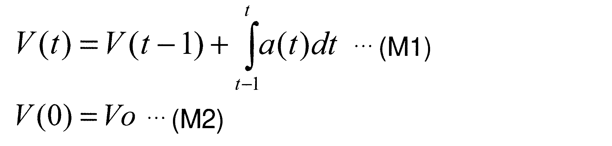
式M1は、前回演算した車速V(t-1)に対して、時刻(t-1)から時刻tまでの期間における加速度a(t)を積分した値を加えることで、現在の車速V(t)を求めることができる。時刻(t-1)から時刻tまでの期間は「サンプリング期間」に相当し、任意の長さ(例えば10[msec]や100[msec]など)を設定してよい。式M2は、車速V(0)として図5のステップS13で取得した車速Voを設定する。このように設定することで、異常状態が発生した後における車速V(t)の正確性が高まる。
そして、車両速度条件を満たすか否かで処理を分岐する(S31)。車両速度条件は、例えばS30で求めた車速V(t)が速度閾値Vthよりも大きいとする条件である。速度閾値Vthは任意に設定してよく、例えば10[Km/h]や16[Km/h]などが該当する。もし、車速V(t)が速度閾値Vthよりも大きければ(V(t)>Vth;S31でYES)、制御部13は車速反映部15にONの制御信号SDを継続して伝達し、車速反映部15はONの制御信号SCを継続してスイッチ部Qに伝達して導通状態を継続する(S32)。よって、バッテリBATから電源部17に電力が供給され続け、乗員保護装置11の起動が可能な状態も継続する。その後は、車速反映処理をリターンして、図5に示すS13に戻る。
一方、車速V(t)が速度閾値Vth以下であれば(V(t)≦Vth;S31でNO)、図7に示す減速期間判定処理と(S33)、図8に示す低速期間判定処理とを実行する(S34)。減速期間判定処理と低速期間判定処理は、図6に示す順序に限らず、順不同で実行してよく、並行処理してもよい。その後は、車速反映処理をリターンして、図5に示す乗員保護装置起動処理のS13に戻る。以下では、減速期間判定処理と低速期間判定処理の一例について説明する。
図7の減速期間判定処理において、車両Cが減速しているか否かで処理を分岐する(S40)。例えば、図6のS30で求めた現在の車速V(t)が前回の車速V(t-1)よりも小さいか否かで判断する。なおS40の括弧内に示すように、図5のS21で取得した加速度a(t)がマイナス値であるか否かで判断してもよい。
S40において、車両Cが減速していれば(V(t)<V(t-1)またはa(t)<0;YES)、減速期間フラグTDFの状態に応じて処理を分岐する(S41)。減速期間フラグTDFは、車速Vが連続して低下しているか否かを示すフラグである。この減速期間フラグTDFは、車両Cが減速し続けている限りはONになり、非減速(すなわち加速または定速)のときはOFFになる。
S41において、減速期間フラグTDFがONであれば(YES)、減速期間TDを増やす(S42)。減速期間TDは、車速Vが連続して低下している期間であり、TD=TD+Tsを演算して求める。左辺の減速期間TDは今回求める減速期間TDである。右辺の減速期間TDは前回求めて記録媒体13aに記録された値である。右辺のサンプリング時間Tsは上述した時刻(t-1)から時刻tまでの期間である。すなわち、減速期間フラグTDFがONであり続ける限り、減速期間TDはサンプリング時間Tsずつ増えてゆく。
そして、減速期間条件を満たすか否かで処理を分岐する(S43)。減速期間条件は、例えば減速期間TDが減速許容期間TDthよりも短いとする条件である。
S43において、減速期間TDが減速許容期間TDthよりも短ければ(TD<TDth;YES)、バッテリBATから電源部17に電力を供給し続け、乗員保護装置11の起動が可能な状態を継続する。具体的には、制御部13から車速反映部15に伝達する制御信号SDと、車速反映部15からスイッチ部Qに伝達する制御信号SCとをONで継続し、スイッチ部Qの導通状態を継続する(S48)。その後は、減速期間判定処理をリターンして、図6の車速反映処理に戻る。
また、S40において車両Cが減速していなければ(V(t)≧V(t-1)またはa(t)≧0;NO)、減速期間フラグTDFをOFFにする(S47)。車両Cは減速していないので、バッテリBATから電源部17に電力を供給し続け、乗員保護装置11の起動が可能な状態を継続するために上記S48を実行する。その後は、減速期間判定処理をリターンして、図6の車速反映処理に戻る。
さらに、S41において減速期間フラグTDFがOFFであれば(NO)、車両Cが減速し始めたので減速期間フラグTDFをONにするとともに(S45)、減速期間TDを0で初期化する(S46)。車両Cは減速し始めたばかりなので、バッテリBATから電源部17に電力を供給し続け、乗員保護装置11の起動が可能な状態を継続するために上記S48を実行する。その後は、減速期間判定処理をリターンして、図6の車速反映処理に戻る。
これに対して、S43において減速期間TDが減速許容期間TDth以上になれば(TD≧TDth;NO)、制御部13は車速反映部15にOFFの制御信号SDを伝達し、車速反映部15はOFFの制御信号SCをスイッチ部Qに伝達して非導通状態にする(S44)。よって、バッテリBATから電源部17に電力が供給されなくなり、乗員保護システム10全体の機能が停止する。乗員保護装置11の起動を可能にする時期を、減速期間TDが減速許容期間TDthを経過するまでに限ることで、バッテリBATの電力消費が抑えられる。
図8の低速期間判定処理において、車両Cが速度閾値Vth以下の車速V(t)で走行しているか否かで処理を分岐する(S50)。例えば、図6のS30で求めた現在の車速V(t)が速度閾値Vth以下か否かで判断する。
S50において、車両Cが速度閾値Vth以下で走行していれば(V(t)≦Vth;YES)、低速期間フラグTLFの状態に応じて処理を分岐する(S51)。低速期間フラグTLFは、車速Vが継続して低速で走行しているか否かを示すフラグである。この低速期間フラグTLFは、車両Cが速度閾値Vth以下の低速で走行している限りはONになり、速度閾値Vthを超えて走行するとOFFになる。
S51において、低速期間フラグTLFがONであれば(YES)、低速期間TLを増やす(S52)。低速期間TLは、車速Vが連続して低下している期間であり、TL=TL+Tsを演算して求める。左辺の低速期間TLは今回求める低速期間TLである。右辺の低速期間TLは前回求めて記録媒体13aに記録された値である。右辺のサンプリング時間Tsは上述した時刻(t-1)から時刻tまでの期間である。すなわち、低速期間フラグTLFがONであり続ける限り、低速期間TLはサンプリング時間Tsずつ増えてゆく。
そして、低速期間条件を満たすか否かで処理を分岐する(S53)。低速期間条件は、例えば低速期間TLが低速許容期間TLthよりも短いとする条件である。低速許容期間TLthは、減速許容期間TDthと同様に、任意の長さを設定してよい。
S53において、低速期間TLが低速許容期間TLthよりも短ければ(TL<TLth;YES)、バッテリBATから電源部17に電力を供給し続け、乗員保護装置11の起動が可能な状態を継続する。具体的には、制御部13から車速反映部15に伝達する制御信号SDと、車速反映部15からスイッチ部Qに伝達する制御信号SCとをONで継続し、スイッチ部Qの導通状態を継続する(S58)。その後は、低速期間判定処理をリターンして、図6の車速反映処理に戻る。
また、S50において車両Cが速度閾値Vthを超えた車速V(t)で走行していれば(V(t)>Vth;NO)、低速期間フラグTLFをOFFにする(S57)。車両Cは低速で走行していないので、バッテリBATから電源部17に電力を供給し続け、乗員保護装置11の起動が可能な状態を継続するために上記S58を実行する。その後は、低速期間判定処理をリターンして、図6の車速反映処理に戻る。
さらに、S51において低速期間フラグTLFがOFFであれば(NO)、車両Cが低速で走行し始めたので低速期間フラグTLFをONにするとともに(S55)、低速期間TLを0で初期化する(S56)。S56で初期化された時が低速期間TLの始期である。図5のS14で供給電圧E1が電圧閾値Eth未満になったとき、上記S50で車速V(t)が速度閾値Vth以下であれば、低速期間TLの始期は基準時STDになる。車両Cは低速で走行し始めたばかりなので、バッテリBATから電源部17に電力を供給し続け、乗員保護装置11の起動が可能な状態を継続するために上記S58を実行する。その後は、低速期間判定処理をリターンして、図6の車速反映処理に戻る。
これに対して、S53において低速期間TLが低速許容期間TLth以上になれば(TL≧TLth;NO)、制御部13は車速反映部15にOFFの制御信号SDを伝達し、車速反映部15はOFFの制御信号SCをスイッチ部Qに伝達して非導通状態にする(S54)。よって、バッテリBATから電源部17に電力が供給されなくなり、乗員保護システム10全体の機能が停止する。乗員保護装置11の起動を可能にする時期を、低速期間TLが低速許容期間TLthを経過するまでに限ることで、バッテリBATの電力消費が抑えられる。
上述した乗員保護装置起動処理(図5),車速反映処理(図6),減速期間判定処理(図7)および低速期間判定処理(図8)を実行した場合における制御例について、図9~図14を参照しながら説明する。
(第1例)
図9に示す第1例は、車両速度条件と減速期間条件を満たしている間、乗員保護装置11の起動が可能な状態を継続する例である。ただし、減速許容期間TDthと低速許容期間TLthの関係は、TDth<TLthとする。
図9に示す第1例は、車両速度条件と減速期間条件を満たしている間、乗員保護装置11の起動が可能な状態を継続する例である。ただし、減速許容期間TDthと低速許容期間TLthの関係は、TDth<TLthとする。
車両Cの走行中において、第1電源線L1の供給電圧E1は、時刻t13まで電圧閾値Ethを超える電圧Eaである。そのため、制御部13は起動部12にONの制御信号SBを伝達し、起動部12はONの制御信号SAによってスイッチ部Qを導通状態にする(図5のS15)。時刻t13以降は電圧閾値Ethよりも低い電圧(図9では0[V])になるので、制御部13は車速反映部15にONの制御信号SDを伝達し、車速反映部15はONの制御信号SCによってスイッチ部Qを導通状態にする(図5のS20)。スイッチ部Qは時刻t13以降も導通状態を維持し、電源部17にはバッテリBATから第2電源線L2を介して供給電圧E2(図9では電圧Eb)の電力が供給され、乗員保護装置11の起動が可能な状態を継続する。
時刻t13まで、制御部13は外部装置20から通信部14を介して車速Voを取得できる。時刻t13以後は、時刻t11から時刻t13までの所定期間FT内に取得して記録媒体13aに記録した車速Voと、加速度センサ16から取得する加速度a(t)とを用いて、現在の車速V(t)を推定する(図6のS30)。そして、時刻t14には車速V(t)が速度閾値Vth以下になるため、時刻t14を始期として減速期間TDをカウントし(図7のS42)、低速期間TLをカウントする(図8のS52)。
時刻t14以降も車速V(t)が減速し続け、時刻t15には減速期間TDが減速許容期間TDth以上になる(図7のS43)。本例の前提条件によって、低速期間TLは低速許容期間TLth内である。減速期間TDが減速許容期間TDth以上になったので、制御部13は車速反映部15にOFFの制御信号SDを伝達し、車速反映部15はOFFの制御信号SCによってスイッチ部Qを非導通状態にする(図7のS44)。したがって、時刻t15までは乗員保護装置11の起動が可能な状態に継続され、時刻t15には乗員保護システム10全体の機能が停止する。例えば、車両Cが上り坂に存在して一時的に減速した後、車両Cが下り始めるような場合であっても、連続して減速することにより車両Cが停止傾向であることを推定することができる。なお車両Cは、時刻t15よりも後の時刻t16に走行を停止した。
(第2例)
図10に示す第2例は、車両速度条件と低速期間条件を満たしている間、乗員保護装置11の起動が可能な状態を継続する例である。減速許容期間TDthと低速許容期間TLthの関係は、第1例と同様にTDth<TLthとする。なお時刻t14までは、上述した図9に示す第1例と同じであるので説明を省略する。
図10に示す第2例は、車両速度条件と低速期間条件を満たしている間、乗員保護装置11の起動が可能な状態を継続する例である。減速許容期間TDthと低速許容期間TLthの関係は、第1例と同様にTDth<TLthとする。なお時刻t14までは、上述した図9に示す第1例と同じであるので説明を省略する。
時刻t14以降も車速V(t)は速度閾値Vth以下であり続け、時刻t17には低速期間TLが低速許容期間TLth以上になる(図8のS53)。ただし、時刻t14から時刻t17までの間に車速V(t)が増加する時もあるため、減速期間TDは減速許容期間TDth内である。低速期間TLが低速許容期間TLth以上になったので、制御部13は車速反映部15にOFFの制御信号SDを伝達し、車速反映部15はOFFの制御信号SCによってスイッチ部Qを非導通状態にする(図8のS54)。したがって、時刻t15までは乗員保護装置11の起動が可能な状態に継続され、時刻t15には乗員保護システム10全体の機能が停止する。車両Cは、時刻t17よりも後の時刻t18に走行を停止した。
(第3例)
図11に示す第3例は、車両速度条件と低速期間条件を満たしている間、乗員保護装置11の起動が可能な状態を継続する例である。ただし、減速許容期間TDthと低速許容期間TLthの関係は、TDth>TLthとする。なお時刻t14までは、上述した図9に示す第1例や図10に示す第2例と同じであるので説明を省略する。
図11に示す第3例は、車両速度条件と低速期間条件を満たしている間、乗員保護装置11の起動が可能な状態を継続する例である。ただし、減速許容期間TDthと低速許容期間TLthの関係は、TDth>TLthとする。なお時刻t14までは、上述した図9に示す第1例や図10に示す第2例と同じであるので説明を省略する。
時刻t14以降も車速V(t)は速度閾値Vth以下であり続け、時刻t20には低速期間TLが低速許容期間TLth以上になる(図8のS53)。本例の前提条件によって、減速期間TDは時刻t14から時刻t21までの減速許容期間TDth内である。低速期間TLが低速許容期間TLth以上になったので、制御部13は車速反映部15にOFFの制御信号SDを伝達し、車速反映部15はOFFの制御信号SCによってスイッチ部Qを非導通状態にする(図8のS54)。したがって、時刻t20までは乗員保護装置11の起動が可能な状態に継続され、時刻t20には乗員保護システム10全体の機能が停止する。車両Cは、時刻t20よりも後の時刻t22に走行を停止した。
(第4例)
図12に示す第4例は、車両速度条件と減速期間条件を満たしている間、乗員保護装置11の起動が可能な状態を継続する例である。ただし、減速許容期間TDthと低速許容期間TLthの関係は、第1例と同様にTDth<TLthとする。第1例との相違は、速度閾値Vthを第1例よりも低く設定することである。なお時刻t13までは、上述した図9に示す第1例や図10に示す第2例と同じであるので説明を省略する。
図12に示す第4例は、車両速度条件と減速期間条件を満たしている間、乗員保護装置11の起動が可能な状態を継続する例である。ただし、減速許容期間TDthと低速許容期間TLthの関係は、第1例と同様にTDth<TLthとする。第1例との相違は、速度閾値Vthを第1例よりも低く設定することである。なお時刻t13までは、上述した図9に示す第1例や図10に示す第2例と同じであるので説明を省略する。
時刻t13よりも後の時刻t30には車速V(t)が速度閾値Vth以下になるため、時刻t30を始期として減速期間TDをカウントし(図7のS42)、低速期間TLをカウントする(図8のS52)。
時刻t30以降も車速V(t)が減速し続け、時刻t32には減速期間TDが減速許容期間TDth以上になる(図7のS43)。本例の前提条件によって、低速期間TLは低速許容期間TLth内である。減速期間TDが減速許容期間TDth以上になったので、制御部13は車速反映部15にOFFの制御信号SDを伝達し、車速反映部15はOFFの制御信号SCによってスイッチ部Qを非導通状態にする(図7のS44)。したがって、時刻t32までは乗員保護装置11の起動が可能な状態に継続され、時刻t32には乗員保護システム10全体の機能が停止する。車両Cは、時刻t32よりも前の時刻t31に走行を停止した。
(第5例)
図13に示す第5例は、車両速度条件と低速期間条件を満たしている間、乗員保護装置11の起動が可能な状態を継続する例である。第1例との相違は、車速V(t)が速度閾値Vth以下になった後に、供給電圧E1が電圧閾値Eth未満になることである。
図13に示す第5例は、車両速度条件と低速期間条件を満たしている間、乗員保護装置11の起動が可能な状態を継続する例である。第1例との相違は、車速V(t)が速度閾値Vth以下になった後に、供給電圧E1が電圧閾値Eth未満になることである。
車両Cの走行中において、第1電源線L1の供給電圧E1は、時刻t44まで電圧閾値Ethを超える電圧Eaである。第1例と同様に、制御部13は起動部12にONの制御信号SBを伝達し、起動部12はONの制御信号SAによってスイッチ部Qを導通状態にする(図5のS15)。時刻t44以降は電圧閾値Ethよりも低い電圧(図13では0[V])になるので、制御部13は車速反映部15にONの制御信号SDを伝達し、車速反映部15はONの制御信号SCによってスイッチ部Qを導通状態にする(図5のS20)。スイッチ部Qは時刻t44以降も導通状態を維持し、電源部17にはバッテリBATから第2電源線L2を介して供給電圧E2(図13では電圧Eb)の電力が供給され、乗員保護装置11の起動が可能な状態を継続する。
時刻t44まで、制御部13は外部装置20から通信部14を介して車速Voを取得できる。時刻t44以後は、時刻t41から時刻t44までの所定期間FT内に取得して記録媒体13aに記録した車速Voと、加速度センサ16から取得する加速度a(t)とを用いて、現在の車速V(t)を推定する(図6のS30)。そして、時刻t44よりも前の時刻t43には車速V(t)が速度閾値Vth以下になるため、時刻t44を始期として減速期間TDをカウントし(図7のS42)、低速期間TLをカウントする(図8のS52)。
時刻t44以降も車速V(t)は速度閾値Vth以下であり続け、時刻t45には低速期間TLが低速許容期間TLth以上になる(図8のS53)。ただし、時刻t44から時刻t45までの間に車速V(t)が増加する時もあるため、減速期間TDは減速許容期間TDth内である。低速期間TLが低速許容期間TLth以上になったので、制御部13は車速反映部15にOFFの制御信号SDを伝達し、車速反映部15はOFFの制御信号SCによってスイッチ部Qを非導通状態にする(図8のS54)。したがって、時刻t45までは乗員保護装置11の起動が可能な状態に継続され、時刻t45には乗員保護システム10全体の機能が停止する。車両Cは、時刻t45よりも後の時刻t46に走行を停止した。
図示を省略するが、図9に示す第1例のように車速V(t)が減速し続ける場合は、減速期間TDが先に減速許容期間TDth以上になる(図7のS43)。この場合、制御部13は車速反映部15にOFFの制御信号SDを伝達し、車速反映部15はOFFの制御信号SCによってスイッチ部Qを非導通状態にする(図7のS44)。
(第6例)
図14に示す第6例は、減速期間条件を満たしている間にイグニッションスイッチIGSWがONになり、乗員保護装置11の起動が可能な状態を継続する例である。減速許容期間TDthと低速許容期間TLthの関係は、第1例と同様にTDth<TLthとする。なお時刻t14までは、上述した図9に示す第1例と同じであるので説明を省略する。
図14に示す第6例は、減速期間条件を満たしている間にイグニッションスイッチIGSWがONになり、乗員保護装置11の起動が可能な状態を継続する例である。減速許容期間TDthと低速許容期間TLthの関係は、第1例と同様にTDth<TLthとする。なお時刻t14までは、上述した図9に示す第1例と同じであるので説明を省略する。
時刻t14以降も車速V(t)が減速し続け、時刻t51には減速期間TDが減速許容期間TDth以上になる(図7のS43)。本例の前提条件によって、低速期間TLは低速許容期間TLth内である。ところが、時刻t51よりも前の時刻t50にはイグニッションスイッチIGSWがONになり、第1電源線L1の供給電圧E1は電圧閾値Ethを超える電圧Eaに戻っている。そのため、起動部12にONの制御信号SBを伝達し、起動部12はONの制御信号SAによってスイッチ部Qを導通状態にする(図5のS15)。車両Cは時刻t51よりも後の時刻t52に停止するが、車両Cが走行しているか否かを問わず、乗員保護装置11の起動が可能な状態に継続される。
(他の実施の形態)
以上では本開示を実施するための形態について説明したが、本開示は当該形態に何ら限定されるものではない。言い換えれば、本開示の要旨を逸脱しない範囲内において、種々なる形態で実施することもできる。例えば、次に示す各形態を実現してもよい。
以上では本開示を実施するための形態について説明したが、本開示は当該形態に何ら限定されるものではない。言い換えれば、本開示の要旨を逸脱しない範囲内において、種々なる形態で実施することもできる。例えば、次に示す各形態を実現してもよい。
上述した実施の形態において、乗員保護システム10は起動部12と車速反映部15を個別に備える構成とした(図2を参照)。この形態に代えて、図15に示すように、起動部12と車速反映部15を一体化させたスイッチ制御部18を備える構成としてもよい。スイッチ制御部18は、起動部12の機能と、車速反映部15の機能を合わせもつ。別体構成か一体構成かの相違に過ぎないので、実施の形態と同様の作用効果が得られる。
上述した実施の形態において、バッテリBATと乗員保護システム10との間を1本の第2電源線L2で接続する構成とした(図2を参照)。この形態に代えて、バッテリBATと乗員保護システム10との間を複数本の第2電源線L2で接続する冗長構成としてもよい。図16には、いずれも第2電源線L2に相当する第2電源線L2a,L2bを示す。第2電源線L2aと第2電源線L2bは、バッテリBATと乗員保護システム10との間に並列接続される。冗長構成とすることにより、第2電源線L2a,L2bのうちで一方の電源線が断線しても、他方の電源線で電力を供給することができ、乗員保護装置11の起動が可能になる。また並列接続することにより、バッテリBATと乗員保護システム10との間における合成抵抗値を低下させ、電源線による電力損失を抑えることができる。図示を省略するが、3本以上の第2電源線L2を並列接続する冗長構成としてもよい。その他については、実施の形態と同様の作用効果が得られる。
上述した実施の形態において、スイッチ部Qとしてトランジスタを用いる構成とした(図2を参照)。この形態に代えて、スイッチ部Qとしてリレーを用いる構成としてもよい。リレーは、磁気型でもよく、半導体型でもよい。バッテリBATから電源部17に電力を供給できるので、実施の形態と同様の作用効果が得られる。
上述した実施の形態において、車両Cとして四輪自動車を適用する構成とした(図1を参照)。この形態に代えて、車両Cとして二輪自動車に適用する構成としてもよい。すなわち、車輪数や動力機関にかかわらず乗員保護装置11を備える自動車に適用できる。車両Cの種類が相違するに過ぎないので、実施の形態と同様の作用効果が得られる。
上述した実施の形態において、各種信号のON/OFFは正論理を適用する構成とした(図9~図14を参照)。この形態に代えて、各種信号のON/OFFに負論理を適用する構成としてもよい。物理値に対する論理値の割り当てが相違するに過ぎないので、実施の形態と同様の作用効果が得られる。
なお「車両」は、車輪数や動力機関を問わない。「乗員保護装置」は、乗員を保護できれば任意の装置を適用してよく、例えばエアバッグやシートベルトプリテンショナなどが該当する。「スイッチ部」は、起動部や車速反映部等によって、導通状態と非導通状態とが切り替えられる任意の素子や部品を適用してよい。例えば、トランジスタやリレー等が該当する。「イグニッションスイッチ」は、車両の走行等のためにバッテリから電力の供給を受けるか否かを切り替えるスイッチであれば任意であり、機械的な鍵を使用するか否かを問わない。「バッテリ」は、乗員保護装置を作動させるための電力を供給できれば種類を問わず任意である。乗員保護装置の「起動」は、衝突等による許容値を超える加速度が検出された場合に乗員保護装置を作動させ得る状態を意味する。
ここで、この出願に記載されるフローチャート、あるいは、フローチャートの処理は、複数のステップ(あるいはセクションと言及される)から構成され、各ステップは、たとえば、S10と表現される。さらに、各ステップは、複数のサブステップに分割されることができる、一方、複数のステップが合わさって一つのステップにすることも可能である。
以上、本開示に係る乗員保護システムの実施形態、構成、態様を例示したが、本開示に係る実施形態、構成、態様は、上述した各実施形態、各構成、各態様に限定されるものではない。例えば、異なる実施形態、構成、態様にそれぞれ開示された技術的部を適宜組み合わせて得られる実施形態、構成、態様についても本開示に係る実施形態、構成、態様の範囲に含まれる。
Claims (7)
- 車両(C)の乗員を保護する乗員保護装置(11)と、
前記車両の加速度(a)を検出する加速度センサ(16)と、
前記加速度センサで検出される加速度に基づいて前記乗員保護装置の作動を制御する制御部(13)と、
バッテリ(BAT)と電源部(17)との間に介在され、導通状態と非導通状態とを切り替え可能なスイッチ部(Q)と、
前記バッテリから前記スイッチ部を介して供給される電力を変換し、少なくとも前記乗員保護装置,前記加速度センサおよび前記制御部に出力する前記電源部とを含む乗員保護システムにおいて、
前記バッテリからイグニッションスイッチ(IGSW)を介して第1電源線(L1)に供給される供給電圧(E1)が電圧閾値(Eth)以上であるか否かにより、前記スイッチ部を導通状態または非導通状態のいずれかに切り替える起動部(12)と、
前記イグニッションスイッチを介さず、かつ、前記スイッチ部を介して前記バッテリと前記電源部との間を電気的に接続する第2電源線(L2)と、
前記加速度センサで検出される加速度を用いて演算した演算値により、前記スイッチ部を導通状態または非導通状態のいずれかに切り替える車速反映部(15)とを有する乗員保護システム。 - 前記制御部は、所定条件を満たす限りにおいて、前記スイッチ部を導通状態に切り替えて継続する制御を行う請求項1に記載の乗員保護システム。
- 前記制御部は、前記所定条件として、前記車両の速度(V)が速度閾値(Vth)よりも大きい車両速度条件を含む請求項2に記載の乗員保護システム。
- 前記制御部は、前記所定条件として、通信可能に接続される外部装置(20)から前記車両の速度が得られない速度未取得条件を含む請求項2または3に記載の乗員保護システム。
- 前記供給電圧が前記電圧閾値未満になる時を基準時(STD,t13,t44)とし、
前記制御部は、前記基準時を含む所定期間(FT)内に得られて記録媒体(13a)に記録された前記車両の速度と、前記基準時からの経過とともに前記加速度センサで検出される加速度とによる演算を行って、前記車両の速度を推定する請求項1から4のいずれか一項に記載の乗員保護システム。 - 前記車両の速度が連続して低下する期間を減速期間(TD)とし、
前記制御部は、前記所定条件として、前記減速期間が減速許容期間(TDth)よりも短い減速期間条件を含む請求項3から5のいずれか一項に記載の乗員保護システム。 - 前記車両の速度が継続して前記速度閾値以下となる期間を低速期間(TL)とし、
前記制御部は、前記所定条件として、前記低速期間が低速許容期間(TLth)よりも短い低速期間条件を含む請求項3から5のいずれか一項に記載の乗員保護システム。
Applications Claiming Priority (2)
| Application Number | Priority Date | Filing Date | Title |
|---|---|---|---|
| JP2015-127257 | 2015-06-25 | ||
| JP2015127257A JP2017007589A (ja) | 2015-06-25 | 2015-06-25 | 乗員保護システム |
Publications (1)
| Publication Number | Publication Date |
|---|---|
| WO2016208107A1 true WO2016208107A1 (ja) | 2016-12-29 |
Family
ID=57584928
Family Applications (1)
| Application Number | Title | Priority Date | Filing Date |
|---|---|---|---|
| PCT/JP2016/002182 Ceased WO2016208107A1 (ja) | 2015-06-25 | 2016-04-26 | 乗員保護システム |
Country Status (2)
| Country | Link |
|---|---|
| JP (1) | JP2017007589A (ja) |
| WO (1) | WO2016208107A1 (ja) |
Citations (3)
| Publication number | Priority date | Publication date | Assignee | Title |
|---|---|---|---|---|
| JPH10194007A (ja) * | 1997-01-09 | 1998-07-28 | Harness Sogo Gijutsu Kenkyusho:Kk | 車両衝突時の電力供給遮断装置 |
| JP2008521691A (ja) * | 2004-12-02 | 2008-06-26 | ダイムラー・アクチェンゲゼルシャフト | 車間距離センサシステムを備える自動車で予防的に作動する保護システムのための方法 |
| JP2014180941A (ja) * | 2013-03-19 | 2014-09-29 | Denso Corp | 車両用乗員保護装置 |
-
2015
- 2015-06-25 JP JP2015127257A patent/JP2017007589A/ja active Pending
-
2016
- 2016-04-26 WO PCT/JP2016/002182 patent/WO2016208107A1/ja not_active Ceased
Patent Citations (3)
| Publication number | Priority date | Publication date | Assignee | Title |
|---|---|---|---|---|
| JPH10194007A (ja) * | 1997-01-09 | 1998-07-28 | Harness Sogo Gijutsu Kenkyusho:Kk | 車両衝突時の電力供給遮断装置 |
| JP2008521691A (ja) * | 2004-12-02 | 2008-06-26 | ダイムラー・アクチェンゲゼルシャフト | 車間距離センサシステムを備える自動車で予防的に作動する保護システムのための方法 |
| JP2014180941A (ja) * | 2013-03-19 | 2014-09-29 | Denso Corp | 車両用乗員保護装置 |
Also Published As
| Publication number | Publication date |
|---|---|
| JP2017007589A (ja) | 2017-01-12 |
Similar Documents
| Publication | Publication Date | Title |
|---|---|---|
| US11752874B2 (en) | Power source system | |
| JP6308225B2 (ja) | 車載電源システム | |
| US11535107B2 (en) | System and method for providing ASIL D fail operational power systems in automated vehicle applications | |
| US10270619B2 (en) | In-vehicle recording system and in-vehicle control apparatus | |
| CN106912014B (zh) | 用于车辆的信息共享系统 | |
| US20140288781A1 (en) | Occupant protection apparatus for vehicle | |
| JP2018180843A (ja) | 車両のデータ記憶装置 | |
| US11919420B2 (en) | Power supply system | |
| WO2015194109A1 (ja) | 車両用緊急通報装置 | |
| JP2018061304A (ja) | 車両用のバックアップ装置 | |
| US9616835B2 (en) | Vehicle-mounted emergency report device | |
| US9994174B2 (en) | Smart power supply interface, vehicle-mounted electronic component with the same and method of controlling the same | |
| JP7456166B2 (ja) | 充電量制御装置、充電量制御方法、および充電量制御プログラム | |
| WO2016208107A1 (ja) | 乗員保護システム | |
| US9168885B2 (en) | Method for power management of wireless automotive modules | |
| US20240331466A1 (en) | Control device and control method | |
| US9738251B2 (en) | Seat belt device | |
| US7246822B2 (en) | Motorized seat belt system | |
| JP2023030279A (ja) | 車載カメラ装置 | |
| KR102515547B1 (ko) | 에어백 시스템 충돌 판단신호 송출 방법 및 장치 | |
| JP2025145022A (ja) | 車載器 | |
| JP6388255B2 (ja) | 緊急通報装置 | |
| EP3325308B1 (en) | Methods and systems for managing an electrical connection between a power regulating device and an energy storage device included in a vehicle | |
| JP2019217795A (ja) | 車両用シートベルト装置 |
Legal Events
| Date | Code | Title | Description |
|---|---|---|---|
| 121 | Ep: the epo has been informed by wipo that ep was designated in this application |
Ref document number: 16813883 Country of ref document: EP Kind code of ref document: A1 |
|
| NENP | Non-entry into the national phase |
Ref country code: DE |
|
| 122 | Ep: pct application non-entry in european phase |
Ref document number: 16813883 Country of ref document: EP Kind code of ref document: A1 |