WO2016204242A1 - Toner supply method, method for manufacturing toner cartridge, and toner cartridge - Google Patents
Toner supply method, method for manufacturing toner cartridge, and toner cartridge Download PDFInfo
- Publication number
- WO2016204242A1 WO2016204242A1 PCT/JP2016/067973 JP2016067973W WO2016204242A1 WO 2016204242 A1 WO2016204242 A1 WO 2016204242A1 JP 2016067973 W JP2016067973 W JP 2016067973W WO 2016204242 A1 WO2016204242 A1 WO 2016204242A1
- Authority
- WO
- WIPO (PCT)
- Prior art keywords
- toner
- container
- toner cartridge
- housing
- storage container
- Prior art date
Links
Images


Classifications
-
- G—PHYSICS
- G03—PHOTOGRAPHY; CINEMATOGRAPHY; ANALOGOUS TECHNIQUES USING WAVES OTHER THAN OPTICAL WAVES; ELECTROGRAPHY; HOLOGRAPHY
- G03G—ELECTROGRAPHY; ELECTROPHOTOGRAPHY; MAGNETOGRAPHY
- G03G15/00—Apparatus for electrographic processes using a charge pattern
- G03G15/06—Apparatus for electrographic processes using a charge pattern for developing
- G03G15/08—Apparatus for electrographic processes using a charge pattern for developing using a solid developer, e.g. powder developer
-
- G—PHYSICS
- G03—PHOTOGRAPHY; CINEMATOGRAPHY; ANALOGOUS TECHNIQUES USING WAVES OTHER THAN OPTICAL WAVES; ELECTROGRAPHY; HOLOGRAPHY
- G03G—ELECTROGRAPHY; ELECTROPHOTOGRAPHY; MAGNETOGRAPHY
- G03G21/00—Arrangements not provided for by groups G03G13/00 - G03G19/00, e.g. cleaning, elimination of residual charge
- G03G21/16—Mechanical means for facilitating the maintenance of the apparatus, e.g. modular arrangements
Definitions
- the present invention relates to a method of supplying recycled toner to a toner cartridge mounted on an image forming apparatus such as a laser printer or a copying machine, a method of manufacturing a recycled toner cartridge, and a toner cartridge.
- the toner cartridge is used in an image forming apparatus such as a laser printer, a copying machine, or a facsimile machine, and forms an image on a recording medium such as paper using toner as is well known.
- an image forming apparatus such as a laser printer, a copying machine, or a facsimile machine
- the recycled toner cartridge is used again by being mounted on the image forming apparatus as a recycled toner cartridge.
- the process of recycling the toner cartridge includes cleaning, replacing damaged parts, replacing worn parts, and replenishing toner. In this recycling process, the toner cartridge is disassembled and reassembled.
- the toner is stored in a toner container (toner hopper) to form an image.
- the toner is normally replenished by being poured into a toner container from the provided opening (for example, a toner replenishing port of Patent Document 1). Then, after the replenishment, the opening is closed, thereby preventing leakage of toner before transportation and use.
- the opening is closed by welding or the like, and the toner replenishing port cannot be used, and the toner cannot be replenished by the conventional methods. .
- the present invention relates to a method for supplying toner to a toner cartridge, the process of removing a part of the housing of the toner cartridge, the process of removing an existing toner storage container disposed in the housing, and the process And a step of joining a new toner container made of a non-flexible material to a part of the casing.
- the method of replenishing toner to the toner cartridge of the present invention for example, a process of forming a hole penetrating a part of a housing and a new toner storage container, and a recycling for not being put in the container from the hole A process of adding toner.
- a new toner storage container is prefilled with toner.
- the method of replenishing toner to the toner cartridge of the present invention for example, a process of forming a hole penetrating a part of a housing and a new toner storage container, and a recycling for not being put in the container from the hole A process of adding toner.
- the hole also penetrates the joint formed by the joining process.
- the agitator and the rotating shaft of the agitator are also excluded from the casing.
- the method of manufacturing a toner cartridge by recycling supplies toner to the housing by a method of supplying toner to the toner cartridge, and closes a hole penetrating a part of the housing and a new toner storage container with a lid.
- a method of manufacturing a toner cartridge by recycling including a process.
- the present invention relates to a recycled toner cartridge, which includes a toner storage container made of an inflexible material containing toner, and a housing containing the toner storage container, the toner storage container and the housing Is a toner cartridge joined by a joining portion.
- the toner cartridge further includes a hole that penetrates the toner storage container and the housing, and a lid that closes the hole.
- the present invention is a method for supplying toner to a toner cartridge, and includes a toner storage container having an opening for discharging the stored toner, and a toner storage container storage for storing the toner storage container.
- a process of removing a part of the cartridge housing, a process of removing the toner container from the toner container container, and a process of arranging a toner container made of an inflexible material in the toner container container And including.
- the toner cartridge is not provided with a hole for replenishing the toner before recycling, the toner can be appropriately replenished.
- FIG. 1 is a cross-sectional view showing the structure of a toner cartridge 10 to be recycled.
- FIG. 2 is a conceptual diagram illustrating the configuration of the image forming apparatus.
- FIG. 3 is a diagram showing one scene of a toner supply method and a toner cartridge manufacturing method according to one embodiment.
- FIG. 4 is a diagram illustrating one scene of one form of toner supply method and toner cartridge manufacturing method.
- FIG. 5 is a diagram illustrating one scene of a toner supply method and a toner cartridge manufacturing method according to one embodiment.
- FIG. 6 is a diagram illustrating one scene of one form of toner supply method and a method of manufacturing a toner cartridge.
- FIG. 7 is a cross-sectional view showing the structure of the toner cartridge 110 by recycling.
- FIG. 1 is a cross-sectional view showing the structure of a toner cartridge 10 to be recycled.
- FIG. 2 is a conceptual diagram illustrating the configuration of the image forming apparatus.
- FIG. 3 is a diagram
- FIG. 8 is a diagram showing a scene of another embodiment of the toner replenishing method and the toner cartridge manufacturing method.
- FIG. 9 is a diagram for explaining the form of the lid 231.
- FIG. 10 is a diagram illustrating a scene of another embodiment of a toner replenishing method and a toner cartridge manufacturing method.
- FIG. 11 is a diagram illustrating a scene of another embodiment of the toner supply method and the toner cartridge manufacturing method.
- FIG. 12 is a view showing another form of the new toner storage container after recycling.
- FIG. 12A shows an example in which perforations and a peeling area are formed
- FIG. 12B shows a slit. An example in which a film that is formed and closes the slit is attached is shown.
- FIG. 1 shows a cross-sectional view of the toner cartridge 10 before recycling.
- the toner cartridge 10 includes a photosensitive drum 11, and includes a charging roller 12 that is adjacent to the photosensitive drum 11 and serves as a means for charging the photosensitive drum 11. Further, a cleaning blade 13 is provided as means for cleaning the surface of the charging roller 12.
- a developing roller 14 as developing means is provided so as to face the photosensitive drum 11, and a developing blade 15 and a toner supply roller 16 are disposed so as to contact the developing roller 14.
- An agitator 17 is provided so as to contact the toner supply roller 16, and one end of the agitator 17 is connected to a rotating shaft 18 that rotates the agitator 17.
- a toner storage container 20 for storing toner is provided.
- the rotation of the agitator 17 makes contact with not only the toner supply roller 16 but also the toner storage container 20, so that the toner storage container 20 is impacted, and the flow of toner disposed in the toner storage container 20 is made to flow. And has a function of facilitating the discharge of the toner from the toner container 20. Therefore, the toner storage container 20 is a flexible container.
- the toner cartridge 10 is held by the first casing 21 and the second casing 22 (the casings 21 and 22) surrounded by each member. More specifically, the first housing 21 is provided with the developing roller 14, the developing blade 15, the toner supply roller 16, the agitator 17, the rotating shaft 18, and the toner storage container 20.
- the toner storage container 20 is stored in a toner storage container storage section 24 defined inside the first casing 21 so that the entire container is contained in the first casing 21.
- the toner storage container 20 is held by the first casing 21 by the holding metal fitting 19 disposed inside the housing.
- the first casing 21 is a box formed by combining and bonding two casing members 21a and 21b (first casing member 21a and second casing member 21b). It is in the shape of a casing.
- the housing member 21b is a member that covers a portion where the toner storage container 20 is disposed.
- the joint portion between the housing member 21a and the housing member 21b is not particularly limited in terms of welding, adhesion, and the like.
- the above-described photosensitive drum 11, charging roller 12, and cleaning blade 13 are disposed in the second housing 22.
- FIG. 2 shows a conceptual diagram of the image forming apparatus 1 including the toner cartridge 10.
- a recording medium such as paper moves as indicated by II in FIG. 2, and is sandwiched between a transfer roll 1a and a photosensitive drum 11 on which an image is formed.
- the image is transferred to a recording medium. Thereafter, the image is fixed on the recording medium by the fixing device 2 and discharged.
- FIGS. 3 to 7 show diagrams for explanation. This will be described with reference to these drawings.
- the housing member 21b facing the toner storage container 20 in the first housing 21 is separated from the housing member 21a.
- the means for separating is not particularly limited, and can be performed by peeling off, cutting, or melting the bonded portion.
- the use of the tool is not particularly limited.
- the position at which the housing member 21b is separated from the housing member 21a is not particularly limited. However, it is preferable to separate at the joining position of the original plurality of members in the first casing 21 before recycling. The original member is joined by an adhesive or the like. At this joining position, it is easy to put a tool such as a metal plate, and the housing member 21a and the housing member 21b can be separated relatively easily. That's why.
- a method for forming the joint portion 30, that is, a method for joining, is not particularly limited, and examples thereof include adhesion, adhesion, welding, and welding.
- the new toner container 120 is made of a material that does not have flexibility and is difficult to deform.
- the shape may be a substantially rectangular parallelepiped shape or a shape adapted to the shape of the toner storage container storage unit 24.
- An opening 120a through which toner can be discharged is provided in a part of the opening 120a.
- the material constituting the new toner container 120 is not particularly limited as long as it does not have flexibility as described above and is not easily deformed.
- a polystyrene-based material or an acrylonitrile-based material having an appropriate thickness. Examples thereof include resin such as cardboard and paper such as cardboard.
- the agitator 17 and the rotating shaft 18 are removed, so that space can be used for that amount, and the toner container 120 having a larger capacity than the toner container 20 is used. It is also possible.
- the housing member 21b and the toner container 120 joined in this way are joined again so as to have the same shape as the first housing 21. That is, the housing member 21b is joined to the housing member 21a.
- the toner storage container 120 is disposed so as to be stored in the toner storage container storage section 24 (see FIG. 6) defined inside the first casing 21, particularly inside the first casing 21.
- a hole 21c is formed in at least a part of the housing member 21b and the toner storage container 120 for the first housing 21 reassembled in this manner.
- the method for opening the hole 21c is not particularly limited, and examples thereof include punching, cutting with a drill, and melting.
- the hole 21 c may be provided so as to penetrate the joint portion 30 described above, or may be a portion that is not the joint portion 30. Further, the position, shape, number, etc. of the holes 21c are not particularly limited.
- the hole 21c is formed after the housing member 21b is joined to the housing member 21a, but the timing for forming the hole 21c is not particularly limited.
- the housing member 21b can be joined to the housing member 21a.
- holes may be formed in advance in each of the housing member 21b and the toner storage container 120, and the holes 21c may be formed by combining these holes.
- the toner for recycling is supplied to the inside of the toner container 120 through the hole 21c.
- a method for fixing the lid 31 to the first housing 21 is not particularly limited, and examples thereof include adhesion, adhesion, tape fixing, welding, and screwing.
- the material of the lid is not particularly limited as long as it can prevent leakage of toner. Examples thereof include rubber, polyurethane, sponge and the like.
- the toner cartridge 110 recycled in the posture shown in FIG. 7 is provided to the user or the like.
- the user can use the provided toner cartridge 110 as soon as it is installed in the image forming apparatus.
- the toner can be appropriately replenished even if the toner cartridge does not have a hole for replenishing the toner before recycling. It is. Further, the toner for recycling can be further supplied by removing the lid 31 and reopening the hole 21c.
- Figures 8 to 11 show diagrams for explaining other forms. As shown in FIG. 4, from the opening formed by separating the casing member 21a, the holding metal fitting 19, the toner storage container 20, the agitator 17, and the rotation arranged in the first casing 21 The axis 18 is excluded.
- a new toner container 220 is prepared, and a part of the outer peripheral surface is joined to the housing member 21b as shown in FIG. At this time, the toner container 220 is joined to the surface of the housing member 21b that is inside the first housing 21.
- the joint part 30 is the same as that described above.
- the new toner container 220 is made of a material that does not have flexibility and is difficult to deform.
- An opening 220a through which toner can flow out is provided in a part of the opening 220a. And this opening part is obstruct
- the toner is filled in advance.
- the seal member 220b prevents the toner from flowing out.
- one end of a string-like seal peeling means 220c is attached to the seal member 220b. That is, by pulling the other end side of the seal peeling means 220 c and peeling the seal member 220 b from the toner storage container 220, the opening 220 a of the toner storage container 220 is opened, and the toner inside the toner storage container 220 is removed. Is configured to exit.
- a handle 220d is provided on the other end side of the seal peeling means 220c so that it can be easily pulled, and convenience for the user is enhanced. Further, by providing the handle 220d, the visibility can be improved and forgetting to pull the seal peeling means 220c can be prevented.
- a hole 221c is opened in the housing member 21b, and a lid 231 is disposed here to close the hole 221c.
- a method for fixing the lid 231 to the housing member 21b is not particularly limited, and examples thereof include adhesion, adhesion, tape fixing, welding, and screwing.
- FIG. 9 shows a plan view of the lid 231.
- the lid 231 is provided with a slit 231b in at least a part thereof.
- the slit 231b is configured so that at least the seal member 220b and the seal peeling means 220c can pass through, but it is preferable that the slit 231b is in close contact with the slit 231b so as not to leak toner.
- a material having both flexibility and sealing properties such as rubber, polyurethane, and sponge, for the portion 231a provided with the slit 231b.
- the slit 231b may be closed with a member such as a tape.
- the seal peeling means 220c passes through the slit 231b, and the handle 220d and the handle 220d side of the seal peeling means 220c are the housing. It arrange
- the housing member 21b and the toner container 220 joined in this manner are joined again so as to have the same shape as that of the first housing 21 as shown in FIG. That is, the housing member 21b is joined to the housing member 21a.
- the toner storage container 220 is disposed so as to be inside the first casing 21.
- FIG. 12 is a view showing another embodiment of a new toner storage container stored in the recycled toner cartridge.
- a perforation 322 is formed in advance in the toner storage container 320, and a peeling area 323 is defined by the perforation 322.
- the perforation 322 is formed in a size that prevents the toner from leaking.
- one end of a string-like or tape-like tear string (peeling means) 321 is connected to one end of the peeling region 323.
- the tear string 321 passes through the slit 231b, and the handle 324 and the handle 324 side of the tear string 321 are disposed outside the housing member 21b.
- the tear area 323 becomes an opening.
- the toner inside the unit is configured to come out of the toner storage container 320.
- a plurality of slits 422 are formed in advance in the toner storage container 420, and a film 423 is attached so as to cover the slits 422.
- One end of the film 423 is connected to one end of a string-like or tape-like tear-off string (peeling means) 421.
- the tear string 421 passes through the slit 231b, and the handle 424 and the handle 424 side of the tear string 421 are disposed outside the housing member 21b.
- the exposed slit 422 becomes an opening, and the toner inside the opening comes out of the toner storage container 420. It is configured as follows.
- the toner can be appropriately replenished even if the toner cartridge does not have a hole for replenishing the toner before recycling. is there. Further, after that, holes can be made in the housing member 21b and the joint portion 30, and the recycling toner can be further supplied as described above.
Abstract
This method for supplying toner to a toner cartridge (10) comprises: a step of disengaging a part (21b) of a housing (21) for a toner cartridge; a step of removing an existing toner storage container (20) disposed in the housing; and a step of joining a new toner storage container (120) made of an inflexible material to the disengaged part of the housing.
Description
本発明は、レーザープリンタや複写機等の画像形成装置に装着されるトナーカートリッジにリサイクルのトナーを補給する方法、これによりリサイクルのトナーカートリッジを製造する方法、及びトナーカートリッジに関する。
The present invention relates to a method of supplying recycled toner to a toner cartridge mounted on an image forming apparatus such as a laser printer or a copying machine, a method of manufacturing a recycled toner cartridge, and a toner cartridge.
トナーカートリッジは、レーザープリンタ、複写機、ファクシミリ等の画像形成装置に用いられており、公知のように、トナーを用いて紙などの記録媒体に画像を形成する。ここで、トナーカートリッジに含まれるトナーが全て消費されると、使用済のトナーカートリッジとして回収され、当該回収されたトナーカートリッジに対してトナーの補給や一部の部品の交換が行われることによりリサイクルがなされる。リサイクルされたトナーカートリッジは、再生トナーカートリッジとして再度画像形成装置に装着されて利用される。
トナーカートリッジのリサイクルの過程としては、清掃、損傷を受けた部品の交換、磨耗した部品の交換、及びトナーの補給が挙げられる。そしてこのリサイクル過程でトナーカートリッジの分解及び再組み立てが行われる。 The toner cartridge is used in an image forming apparatus such as a laser printer, a copying machine, or a facsimile machine, and forms an image on a recording medium such as paper using toner as is well known. Here, when all of the toner contained in the toner cartridge is consumed, it is collected as a used toner cartridge, and recycled by supplying toner to the collected toner cartridge or replacing some parts. Is made. The recycled toner cartridge is used again by being mounted on the image forming apparatus as a recycled toner cartridge.
The process of recycling the toner cartridge includes cleaning, replacing damaged parts, replacing worn parts, and replenishing toner. In this recycling process, the toner cartridge is disassembled and reassembled.
画像を形成するためトナーはトナー容器(トナーホッパー)に蓄えられている。リサイクルにおいて、通常、トナーは、設けられた開口部からトナー容器に注がれることで補給される(例えば特許文献1のトナー補給口)。そして補給後に当該開口部が塞がれ、これにより輸送や使用前のトナーの漏れが防止されている。
The toner is stored in a toner container (toner hopper) to form an image. In recycling, the toner is normally replenished by being poured into a toner container from the provided opening (for example, a toner replenishing port of Patent Document 1). Then, after the replenishment, the opening is closed, thereby preventing leakage of toner before transportation and use.
しかしながら、トナーカートリッジの種類によっては開口が溶接される等して塞がれており、トナー補給口を利用することができず、これまでの方法でトナーの補給をすることができないことがあった。
However, depending on the type of toner cartridge, the opening is closed by welding or the like, and the toner replenishing port cannot be used, and the toner cannot be replenished by the conventional methods. .
そこで本発明は上記問題点に鑑み、リサイクル前においてトナーを補給するための開口が設けられていないトナーカートリッジであっても適切にトナーの補給が可能なトナーの補給方法を提供することを課題とする。また、これによりリサイクルされたトナーカートリッジの製造方法、及びトナーカートリッジを提供する。
SUMMARY OF THE INVENTION In view of the above problems, it is an object of the present invention to provide a toner replenishing method capable of appropriately replenishing toner even if the toner cartridge is not provided with an opening for replenishing toner before recycling. To do. In addition, a method for manufacturing a recycled toner cartridge and a toner cartridge are provided.
本発明は、トナーカートリッジにトナーを補給する方法であって、トナーカートリッジの筐体の一部を離脱する過程と、筐体内に配置されていた既存のトナー収納容器を除外する過程と、離脱した筐体の一部に非可撓性材料からなる新たなトナー収納容器を接合する過程と、を含む、トナーカートリッジにトナーを補給する方法である。
The present invention relates to a method for supplying toner to a toner cartridge, the process of removing a part of the housing of the toner cartridge, the process of removing an existing toner storage container disposed in the housing, and the process And a step of joining a new toner container made of a non-flexible material to a part of the casing.
本発明のトナーカートリッジにトナーを補給する方法の一態様として、例えば、筐体の一部及び新たなトナー収納容器を貫通する穴を形成する過程と、穴から、容器に入れられていないリサイクル用のトナーを入れる過程と、を含む。
As one aspect of the method of replenishing toner to the toner cartridge of the present invention, for example, a process of forming a hole penetrating a part of a housing and a new toner storage container, and a recycling for not being put in the container from the hole A process of adding toner.
本発明のトナーカートリッジにトナーを補給する方法の一態様として、例えば、新たなトナー収納容器にあらかじめトナーが充填されている。
As one aspect of the method for supplying toner to the toner cartridge of the present invention, for example, a new toner storage container is prefilled with toner.
本発明のトナーカートリッジにトナーを補給する方法の一態様として、例えば、筐体の一部及び新たなトナー収納容器を貫通する穴を形成する過程と、穴から、容器に入れられていないリサイクル用のトナーを入れる過程と、を含む。
As one aspect of the method of replenishing toner to the toner cartridge of the present invention, for example, a process of forming a hole penetrating a part of a housing and a new toner storage container, and a recycling for not being put in the container from the hole A process of adding toner.
本発明のトナーカートリッジにトナーを補給する方法の一態様として、例えば、穴は、接合する過程により形成された接合部も貫通している。
As one aspect of the method for replenishing toner to the toner cartridge of the present invention, for example, the hole also penetrates the joint formed by the joining process.
本発明のトナーカートリッジにトナーを補給する方法の一態様として、例えば、筐体からはアジテーター及び該アジテーターの回転軸も除外する。
As one aspect of the method of replenishing toner to the toner cartridge of the present invention, for example, the agitator and the rotating shaft of the agitator are also excluded from the casing.
本発明のリサイクルによるトナーカートリッジの製造方法は、トナーカートリッジにトナーを補給する方法により、筐体にトナーを補給し、筐体の一部及び新たなトナー収納容器を貫通する穴をフタにより閉鎖する工程を含む、リサイクルによるトナーカートリッジの製造方法である。
The method of manufacturing a toner cartridge by recycling according to the present invention supplies toner to the housing by a method of supplying toner to the toner cartridge, and closes a hole penetrating a part of the housing and a new toner storage container with a lid. A method of manufacturing a toner cartridge by recycling, including a process.
本発明は、リサイクルされたトナーカートリッジであって、トナーが内包された非可撓性材料からなるトナー収納容器と、トナー収納容器を内包する筐体と、を有し、トナー収納容器と筐体とは接合部により接合されている、トナーカートリッジである。
The present invention relates to a recycled toner cartridge, which includes a toner storage container made of an inflexible material containing toner, and a housing containing the toner storage container, the toner storage container and the housing Is a toner cartridge joined by a joining portion.
本発明のトナーカートリッジの一態様として、例えば、さらに、トナー収納容器及び筐体を貫通する穴を有し、穴を塞ぐフタを具備している。
As an aspect of the toner cartridge of the present invention, for example, the toner cartridge further includes a hole that penetrates the toner storage container and the housing, and a lid that closes the hole.
本発明は、トナーカートリッジにトナーを補給する方法であって、収納したトナーを排出するための開口部を有するトナー収納容器と、前記トナー収納容器を収納するトナー収納容器収納部と、を有するトナーカートリッジ筐体の一部を離脱する過程と、前記トナー収納容器を前記トナー収納容器収納部から除外する過程と、前記トナー収納容器収納部に非可撓性材料からなるトナー収納容器を配置する過程と、を含む。
The present invention is a method for supplying toner to a toner cartridge, and includes a toner storage container having an opening for discharging the stored toner, and a toner storage container storage for storing the toner storage container. A process of removing a part of the cartridge housing, a process of removing the toner container from the toner container container, and a process of arranging a toner container made of an inflexible material in the toner container container And including.
本発明によれば、リサイクル前においてトナーを補給するための穴が設けられていないトナーカートリッジであっても適切にトナーの補給が可能となる。
According to the present invention, even if the toner cartridge is not provided with a hole for replenishing the toner before recycling, the toner can be appropriately replenished.
以下本発明を図面に示す形態に基づき説明する。ただし本発明はこれら形態に限定されるものではない。
Hereinafter, the present invention will be described based on embodiments shown in the drawings. However, the present invention is not limited to these forms.
図1にはリサイクル前におけるトナーカートリッジ10の断面図を示した。トナーカートリッジ10は、図1に示すように感光体ドラム11を備え、該感光体ドラム11に隣接し、感光体ドラム11を帯電させる手段である帯電ローラ12を具備している。さらに帯電ローラ12の表面をクリーニングする手段としてクリーニングブレード13が設けられている。
FIG. 1 shows a cross-sectional view of the toner cartridge 10 before recycling. As shown in FIG. 1, the toner cartridge 10 includes a photosensitive drum 11, and includes a charging roller 12 that is adjacent to the photosensitive drum 11 and serves as a means for charging the photosensitive drum 11. Further, a cleaning blade 13 is provided as means for cleaning the surface of the charging roller 12.
また、感光体ドラム11に対向するように、現像手段である現像ローラ14が具備され、現像ローラ14に接触するように現像ブレード15、及びトナー供給ローラ16が配置されている。そして、トナー供給ローラ16に接触するように、アジテーター17が備えられ、アジテーター17を回転させる回転軸18にアジテーター17の一端が接続されている。さらに、トナーを収納するトナー収納容器20が備えられている。ここでアジテーター17はその回転により、トナー供給ローラ16のみならずトナー収納容器20にも接触することで、トナー収納容器20に衝撃を与え、トナー収納容器20内に配置されているトナーの流動を促して、トナーをトナー収納容器20から排出しやすくする機能を有する。従ってトナー収納容器20は可撓性を有する容器である。
Further, a developing roller 14 as developing means is provided so as to face the photosensitive drum 11, and a developing blade 15 and a toner supply roller 16 are disposed so as to contact the developing roller 14. An agitator 17 is provided so as to contact the toner supply roller 16, and one end of the agitator 17 is connected to a rotating shaft 18 that rotates the agitator 17. Further, a toner storage container 20 for storing toner is provided. Here, the rotation of the agitator 17 makes contact with not only the toner supply roller 16 but also the toner storage container 20, so that the toner storage container 20 is impacted, and the flow of toner disposed in the toner storage container 20 is made to flow. And has a function of facilitating the discharge of the toner from the toner container 20. Therefore, the toner storage container 20 is a flexible container.
図1からわかるように、本形態ではトナーカートリッジ10は、第一の筐体21及び第二の筐体22(筐体21および22)により各部材が囲まれて保持されている。より具体的には、第一の筐体21には、上記した現像ローラ14、現像ブレード15、トナー供給ローラ16、アジテーター17、回転軸18、及びトナー収納容器20が配置されている。特にトナー収納容器20はその全部が第一の筐体21に内包されるように、第一の筐体21の内部に画定されたトナー収納容器収納部24に収納され、第一の筐体21の内側に配置された保持金具19によりトナー収納容器20が第一の筐体21に保持されるように構成されている。
As can be seen from FIG. 1, in this embodiment, the toner cartridge 10 is held by the first casing 21 and the second casing 22 (the casings 21 and 22) surrounded by each member. More specifically, the first housing 21 is provided with the developing roller 14, the developing blade 15, the toner supply roller 16, the agitator 17, the rotating shaft 18, and the toner storage container 20. In particular, the toner storage container 20 is stored in a toner storage container storage section 24 defined inside the first casing 21 so that the entire container is contained in the first casing 21. The toner storage container 20 is held by the first casing 21 by the holding metal fitting 19 disposed inside the housing.
なお、本形態で第一の筐体21は、2つの筐体用部材21a、21b(第一の筐体用部材21aおよび第二の筐体用部材21b)が組み合わされ接合されることにより箱状とされて筐体となっている。特に筐体用部材21bは、トナー収納容器20が配置された部位を覆っている部材である。筐体用部材21aと筐体用部材21bとの接合部は溶着、接着等、特にその態様は限定されることはない。一方、第二の筐体22には、上記した感光体ドラム11、帯電ローラ12、及びクリーニングブレード13が配置されている。
In this embodiment, the first casing 21 is a box formed by combining and bonding two casing members 21a and 21b (first casing member 21a and second casing member 21b). It is in the shape of a casing. In particular, the housing member 21b is a member that covers a portion where the toner storage container 20 is disposed. The joint portion between the housing member 21a and the housing member 21b is not particularly limited in terms of welding, adhesion, and the like. On the other hand, the above-described photosensitive drum 11, charging roller 12, and cleaning blade 13 are disposed in the second housing 22.
トナーカートリッジ10により、感光体ドラム11に像が形成される過程は公知の通りである。すなわち、概ね次の通りである。
The process in which an image is formed on the photosensitive drum 11 by the toner cartridge 10 is known. That is, it is as follows.
図2にトナーカートリッジ10を備える画像形成装置1の概念図を示した。この画像形成装置1によれば、紙等の記録媒体が図2にIIで示したように移動し、転写ロール1aと、像が表面に形成された感光体ドラム11と、の間に挟まれ、当該像が記録媒体に転写される。その後、定着装置2により記録媒体に像が定着され、排出される。
FIG. 2 shows a conceptual diagram of the image forming apparatus 1 including the toner cartridge 10. According to this image forming apparatus 1, a recording medium such as paper moves as indicated by II in FIG. 2, and is sandwiched between a transfer roll 1a and a photosensitive drum 11 on which an image is formed. The image is transferred to a recording medium. Thereafter, the image is fixed on the recording medium by the fixing device 2 and discharged.
次にトナーカートリッジ10において、トナー収納容器20の中のトナーを使い切ったときに、トナーカートリッジにトナーを補給する方法、及びリサイクルのトナーカートリッジの製造方法の1つの形態について説明する。図3~図7に説明のための図を表した。これらの図を参照しつつ説明する。
Next, in the toner cartridge 10, one embodiment of a method for supplying toner to the toner cartridge when the toner in the toner container 20 is used up and a method for manufacturing a recycled toner cartridge will be described. FIGS. 3 to 7 show diagrams for explanation. This will be described with reference to these drawings.
はじめに、図3に示したように、第一の筐体21のうち、トナー収納容器20に面する筐体用部材21bを筐体用部材21aから分離する。分離する手段は特に限定されることなく、接着部分を引き剥がしたり、切断したり、溶かしたりすることで行うことができる。工具の利用についても特に限定されることはない。筐体用部材21bを筐体用部材21aから分離する位置も特に限定はされない。ただし、リサイクル前の第一の筐体21における、元の複数の部材の接合位置において分離することが好ましい。元の部材は、接着剤等によって接合されており、この接合位置においては、金属板の如き工具を入れやすく、筐体用部材21aと筐体用部材21bを比較的容易に分離することが可能だからである。
First, as shown in FIG. 3, the housing member 21b facing the toner storage container 20 in the first housing 21 is separated from the housing member 21a. The means for separating is not particularly limited, and can be performed by peeling off, cutting, or melting the bonded portion. The use of the tool is not particularly limited. The position at which the housing member 21b is separated from the housing member 21a is not particularly limited. However, it is preferable to separate at the joining position of the original plurality of members in the first casing 21 before recycling. The original member is joined by an adhesive or the like. At this joining position, it is easy to put a tool such as a metal plate, and the housing member 21a and the housing member 21b can be separated relatively easily. That's why.
次に、図4に示したように、筐体用部材21aを分離したことにより形成された開口から、第一の筐体21内に配置されていた保持金具19、トナー収納容器20、アジテーター17、及び回転軸18を除外する。除外に際して切断や破壊が必要な場合もある。特に、トナー収納容器20が可撓性材料である場合には、トナーがトナー収納容器20に付着しているので、リサイクル前後のトナーが混ざり合い画質が低下したり、リサイクル後のトナーがトナー収納容器20に付着してトナー消費限界量が減少する事態が発生し得る。したがって、トナー収納容器20を第一の筐体21のトナー収納容器収納部24(図1参照)から除外することにより、このような事態の発生を防止することができる。
Next, as shown in FIG. 4, from the opening formed by separating the casing member 21a, the holding metal fitting 19, the toner storage container 20, and the agitator 17 arranged in the first casing 21. , And the rotating shaft 18 are excluded. In some cases, cutting or destruction is necessary for exclusion. In particular, when the toner storage container 20 is made of a flexible material, the toner adheres to the toner storage container 20, so that the toner before and after recycling is mixed and the image quality is lowered, or the toner after recycling is stored in the toner. A situation may occur in which the toner consumption limit amount decreases due to adhesion to the container 20. Therefore, by excluding the toner storage container 20 from the toner storage container storage section 24 (see FIG. 1) of the first housing 21, such a situation can be prevented.
次に、新たなトナー収納容器120を準備し、図5に示したようにその外周面の一部を筐体用部材21bに接合して接合部30を形成する。このときには筐体用部材21bのうち、第一の筐体21の内側となる面にトナー収納容器120を接合する。接合部30を形成する方法、すなわち接合する方法は特に限定されることはなく、接着、粘着、溶着、溶接などを挙げることができる。
Next, a new toner container 120 is prepared, and a part of the outer peripheral surface is joined to the housing member 21b as shown in FIG. At this time, the toner storage container 120 is joined to a surface of the housing member 21b that is inside the first housing 21. A method for forming the joint portion 30, that is, a method for joining, is not particularly limited, and examples thereof include adhesion, adhesion, welding, and welding.
ここで、新たなトナー収納容器120は、可撓性を有しない変形し難い材料により構成されている。その形状は、略直方体であってもトナー収納容器収納部24の形に適合した形状でであってもよい。そしてその一部にはトナーが排出可能な開口部120aが設けられている。新たなトナー収納容器120を構成する材料は、上記のように可撓性を有しない変形し難いものであれば特に限定されることはないが、例えば適度な厚みを持ったポリスチレン系、アクリロニトリル系等の樹脂や、ダンボール等の紙を挙げることができる。
Here, the new toner container 120 is made of a material that does not have flexibility and is difficult to deform. The shape may be a substantially rectangular parallelepiped shape or a shape adapted to the shape of the toner storage container storage unit 24. An opening 120a through which toner can be discharged is provided in a part of the opening 120a. The material constituting the new toner container 120 is not particularly limited as long as it does not have flexibility as described above and is not easily deformed. For example, a polystyrene-based material or an acrylonitrile-based material having an appropriate thickness. Examples thereof include resin such as cardboard and paper such as cardboard.
本形態ではアジテーターを必要としないことから、アジテーター17及び回転軸18を除去しているので、その分に空間を利用することができ、トナー収納容器20よりも容量の大きなトナー収納容器120を用いることも可能である。
In this embodiment, since an agitator is not required, the agitator 17 and the rotating shaft 18 are removed, so that space can be used for that amount, and the toner container 120 having a larger capacity than the toner container 20 is used. It is also possible.
次にこのようにして接合した筐体用部材21b及びトナー収納容器120を再び第一の筐体21と同じ形状となるように接合する。すなわち、筐体用部材21aに筐体用部材21bを接合する。このときトナー収納容器120は第一の筐体21の内側、特に第一の筐体21の内側に画定されるトナー収納容器収納部24(図6参照)に収納されるように配置される。
Next, the housing member 21b and the toner container 120 joined in this way are joined again so as to have the same shape as the first housing 21. That is, the housing member 21b is joined to the housing member 21a. At this time, the toner storage container 120 is disposed so as to be stored in the toner storage container storage section 24 (see FIG. 6) defined inside the first casing 21, particularly inside the first casing 21.
このようにして再度組み立てられた第一の筐体21に対して、図6に示したように、筐体用部材21b及びトナー収納容器120の少なくとも一部に穴21cを開ける。穴21cを開ける方法は特に限定されることはないが、打ち抜き、ドリルによる切削、溶融等を挙げることができる。このとき当該穴21cは、図6に表れているように上記した接合部30を貫通するようにして設けられてもよいし、接合部30でない部位であってもよい。また、穴21cの位置、形状、数などは特に限定されない。
As shown in FIG. 6, a hole 21c is formed in at least a part of the housing member 21b and the toner storage container 120 for the first housing 21 reassembled in this manner. The method for opening the hole 21c is not particularly limited, and examples thereof include punching, cutting with a drill, and melting. At this time, as shown in FIG. 6, the hole 21 c may be provided so as to penetrate the joint portion 30 described above, or may be a portion that is not the joint portion 30. Further, the position, shape, number, etc. of the holes 21c are not particularly limited.
また、図5、図6の例では、筐体用部材21aに筐体用部材21bを接合した後、穴21cを形成しているが、穴21cを形成するタイミングは特に限定はされない。例えば、筐体用部材21bに穴21cを形成した後、筐体用部材21bを筐体用部材21aに接合することができる。また、予め筐体用部材21bと、トナー収納容器120のそれぞれに予め穴を形成しておき、これらを組み合わせて穴21cを形成してもよい。
5 and 6, the hole 21c is formed after the housing member 21b is joined to the housing member 21a, but the timing for forming the hole 21c is not particularly limited. For example, after forming the hole 21c in the housing member 21b, the housing member 21b can be joined to the housing member 21a. Alternatively, holes may be formed in advance in each of the housing member 21b and the toner storage container 120, and the holes 21c may be formed by combining these holes.
このようにして穴21cが形成された後、図6に矢印VIで示したように、リサイクル用のトナーを穴21cを通してトナー収納容器120の内側に補給する。
After the hole 21c is formed in this way, as shown by the arrow VI in FIG. 6, the toner for recycling is supplied to the inside of the toner container 120 through the hole 21c.
リサイクル用のトナーがトナー収納容器120内に供給された後に、図7に示したように、第一の筐体21の筐体用部材21bに形成された穴21cをフタ31で塞ぐ。フタ31を第一の筐体21に固定する方法は特に限定されることはないが、接着、粘着、テープ止め、溶着、及び、ねじ止め等を挙げることができる。またフタの材質も特に限定されることはないが、トナーの漏れを防ぐことができる材料であればよい。これには例えばゴム、ポリウレタン、スポンジ等を挙げることができる。
After the toner for recycling is supplied into the toner container 120, the hole 21c formed in the housing member 21b of the first housing 21 is closed with the lid 31, as shown in FIG. A method for fixing the lid 31 to the first housing 21 is not particularly limited, and examples thereof include adhesion, adhesion, tape fixing, welding, and screwing. The material of the lid is not particularly limited as long as it can prevent leakage of toner. Examples thereof include rubber, polyurethane, sponge and the like.
そして図7に示した姿勢で運搬や保管が行われる。すなわち図7に示した姿勢でリサイクルされたトナーカートリッジ110として、ユーザー等に提供される。ユーザーは提供されたトナーカートリッジ110を画像形成装置に装着すればすぐに利用することができる。
And it is transported and stored in the posture shown in FIG. That is, the toner cartridge 110 recycled in the posture shown in FIG. 7 is provided to the user or the like. The user can use the provided toner cartridge 110 as soon as it is installed in the image forming apparatus.
以上のようなトナーの補給方法、及びリサイクルされたトナーカートリッジの製造方法によれば、リサイクル前においてトナーを補給するための穴が設けられていないトナーカートリッジであっても適切にトナーの補給が可能である。また、フタ31を離脱して穴21cを再度開口させることにより、さらにリサイクル用トナーを補給することができる。
According to the toner replenishing method and the manufacturing method of the recycled toner cartridge as described above, the toner can be appropriately replenished even if the toner cartridge does not have a hole for replenishing the toner before recycling. It is. Further, the toner for recycling can be further supplied by removing the lid 31 and reopening the hole 21c.
このとき、リサイクルに供される新たなトナー収納容器として非可撓性の容器を用いているので、トナーを供給しやすく、穴開けや封止が容易となる。また、破損にし難いので一部の破損による異物混入が防止され、画像欠陥が生じることも抑制することができる。
At this time, since a non-flexible container is used as a new toner storage container to be recycled, toner can be easily supplied, and drilling and sealing are facilitated. In addition, since it is difficult to break, contamination by foreign matters due to partial breakage can be prevented, and image defects can be suppressed.
図8~図11に他の形態について説明する図を示した。図4に示したように、筐体用部材21aを分離したことにより形成された開口から、第一の筐体21内に配置されていた保持金具19、トナー収納容器20、アジテーター17、及び回転軸18を除外する。
Figures 8 to 11 show diagrams for explaining other forms. As shown in FIG. 4, from the opening formed by separating the casing member 21a, the holding metal fitting 19, the toner storage container 20, the agitator 17, and the rotation arranged in the first casing 21 The axis 18 is excluded.
次に、新たなトナー収納容器220を準備し、図8に示したようにその外周面の一部を筐体用部材21bに接合して接合部30を形成する。このときには筐体用部材21bのうち、第一の筐体21の内側となる面にトナー収納容器220を接合する。接合部30は上記した形態と同様である。
Next, a new toner container 220 is prepared, and a part of the outer peripheral surface is joined to the housing member 21b as shown in FIG. At this time, the toner container 220 is joined to the surface of the housing member 21b that is inside the first housing 21. The joint part 30 is the same as that described above.
ここで、新たなトナー収納容器220は、可撓性を有しない変形し難い材料により構成されている。そしてその一部にはトナーが流出可能な開口部220aが設けられている。そして、この開口部がフィルム状のシール部材220bにより閉塞されている。本形態では、予めトナーが充填されている。そしてシール部材220bによりトナーの流出が防がれている。
Here, the new toner container 220 is made of a material that does not have flexibility and is difficult to deform. An opening 220a through which toner can flow out is provided in a part of the opening 220a. And this opening part is obstruct | occluded with the film-like sealing member 220b. In this embodiment, the toner is filled in advance. The seal member 220b prevents the toner from flowing out.
また、このシール部材220bには紐状のシール剥離手段220cの一端が取り付けられている。すなわち、このシール剥離手段220cの他端側を引き、シール部材220bをトナー収納容器220から引き剥がすことで、トナー収納容器220の開口部220aが開放され中のトナーがトナー収納容器220の外に出るように構成されている。なお、シール剥離手段220cの他端側には持ち手220dが設けられて引きやすくなっており、利用者の利便性が高められる。また、この持ち手220dを備えることで、視認性が高められ、シール剥離手段220cの引き忘れを防止することもできる。
Further, one end of a string-like seal peeling means 220c is attached to the seal member 220b. That is, by pulling the other end side of the seal peeling means 220 c and peeling the seal member 220 b from the toner storage container 220, the opening 220 a of the toner storage container 220 is opened, and the toner inside the toner storage container 220 is removed. Is configured to exit. In addition, a handle 220d is provided on the other end side of the seal peeling means 220c so that it can be easily pulled, and convenience for the user is enhanced. Further, by providing the handle 220d, the visibility can be improved and forgetting to pull the seal peeling means 220c can be prevented.
一方、筐体用部材21bには、穴221cを開けここにフタ231を配置して穴221cを塞ぐ。フタ231を筐体用部材21bに固定する方法は特に限定されることはないが、接着、粘着、テープ止め、溶着、及び、ねじ止め等を挙げることができる。
On the other hand, a hole 221c is opened in the housing member 21b, and a lid 231 is disposed here to close the hole 221c. A method for fixing the lid 231 to the housing member 21b is not particularly limited, and examples thereof include adhesion, adhesion, tape fixing, welding, and screwing.
ここで本形態のフタ231は次のような形態を具備している。図9にフタ231を平面視した図を表した。フタ231は、その少なくとも一部にスリット231bが設けられている。このスリット231bには少なくともシール部材220b、及びシール剥離手段220cが通過できるように構成されるが、通過した後にはスリット231bからトナーがもれないようにしっかりと接触していることが好ましい。かかる観点から、スリット231bが設けられる部分231aについては、ゴム、ポリウレタン、スポンジ等の柔軟性とシーリング性を兼ね備えた材料を用いることが好ましい。もちろん、テープ等の部材でスリット231bを塞いでもよい。
Here, the lid 231 of this embodiment has the following configuration. FIG. 9 shows a plan view of the lid 231. The lid 231 is provided with a slit 231b in at least a part thereof. The slit 231b is configured so that at least the seal member 220b and the seal peeling means 220c can pass through, but it is preferable that the slit 231b is in close contact with the slit 231b so as not to leak toner. From this point of view, it is preferable to use a material having both flexibility and sealing properties, such as rubber, polyurethane, and sponge, for the portion 231a provided with the slit 231b. Of course, the slit 231b may be closed with a member such as a tape.
そして、このようにフタ231が穴221cを塞いだ姿勢において、図8からわかるように、シール剥離手段220cがスリット231bを通過し、持ち手220d、及びシール剥離手段220cのうち持ち手220d側が筐体用部材21bの外に配置される。
In the posture in which the lid 231 closes the hole 221c in this way, as can be seen from FIG. 8, the seal peeling means 220c passes through the slit 231b, and the handle 220d and the handle 220d side of the seal peeling means 220c are the housing. It arrange | positions out of the body member 21b.
次にこのようにして接合した筐体用部材21b及びトナー収納容器220を、図10に示したように、再び第一の筐体21と同じ形状となるように接合する。すなわち、筐体用部材21aに筐体用部材21bを接合する。このときトナー収納容器220は第一の筐体21の内側となるように配置される。
Next, the housing member 21b and the toner container 220 joined in this manner are joined again so as to have the same shape as that of the first housing 21 as shown in FIG. That is, the housing member 21b is joined to the housing member 21a. At this time, the toner storage container 220 is disposed so as to be inside the first casing 21.
このようにして再度組み立てられた第一の筐体21に対して、図11に示したように持ち手220dを引っ張り、シール剥離手段220cを引くことで、シール部材220が剥離して開口部220aが開放される。これによりトナーが、トナー収納容器220から流出することができる。なお、引き抜かれたシール剥離手段220c及びシール部材220bはフタ231のスリット231bを通過して外部に取り出される。
By pulling the handle 220d and pulling the seal peeling means 220c as shown in FIG. 11 with respect to the first casing 21 reassembled in this manner, the seal member 220 is peeled and the opening 220a is peeled off. Is released. As a result, the toner can flow out of the toner container 220. The pulled-off seal peeling means 220c and the seal member 220b are taken out through the slit 231b of the lid 231.
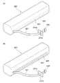
図12は、リサイクルされたトナーカートリッジに収納される新たなトナー収納容器の他の形態を示す図である。図12(a)ではトナー収納容器320において、予めミシン目322が形成され、ミシン目322により引き剥がし領域323が画定されている。ミシン目322は、トナーが漏れない程度の大きさで形成されている。また、引き剥がし領域323の一端には、紐状またはテープ状の引き剥がし紐(引き剥がし手段)321の一端が接続されている。引き剥がし紐321は、スリット231bを通過し、持ち手324、及び引き剥がし紐321のうち持ち手324側が筐体用部材21bの外に配置される。
FIG. 12 is a view showing another embodiment of a new toner storage container stored in the recycled toner cartridge. In FIG. 12A, a perforation 322 is formed in advance in the toner storage container 320, and a peeling area 323 is defined by the perforation 322. The perforation 322 is formed in a size that prevents the toner from leaking. Further, one end of a string-like or tape-like tear string (peeling means) 321 is connected to one end of the peeling region 323. The tear string 321 passes through the slit 231b, and the handle 324 and the handle 324 side of the tear string 321 are disposed outside the housing member 21b.
引き剥がし紐321の持ち手324側を引き、引き剥がし領域323の周囲のミシン目32を引き裂き、引き剥がし領域323をトナー収納容器320から引き剥がすことにより引き剥がし領域323が開口部となり、この開口部から中のトナーがトナー収納容器320の外に出るように構成されている。
By pulling the handle 324 side of the tear string 321, tearing the perforation 32 around the tear area 323, and tearing the tear area 323 from the toner container 320, the tear area 323 becomes an opening. The toner inside the unit is configured to come out of the toner storage container 320.
図12(b)ではトナー収納容器420において、予め複数のスリット422が形成されており、スリット422を覆うようにフィルム423が貼付されている。フィルム423の一端には、紐状またはテープ状の引き剥がし紐(引き剥がし手段)421の一端が接続されている。引き剥がし紐421は、スリット231bを通過し、持ち手424、及び引き剥がし紐421のうち持ち手424側が筐体用部材21bの外に配置される。
In FIG. 12B, a plurality of slits 422 are formed in advance in the toner storage container 420, and a film 423 is attached so as to cover the slits 422. One end of the film 423 is connected to one end of a string-like or tape-like tear-off string (peeling means) 421. The tear string 421 passes through the slit 231b, and the handle 424 and the handle 424 side of the tear string 421 are disposed outside the housing member 21b.
引き剥がし紐421の持ち手424側を引き、フィルム423をトナー収納容器420から引き剥がすことで、露出したスリット422が開口部となり、この開口部から中のトナーがトナー収納容器420の外に出るように構成されている。
By pulling the handle 424 side of the peeling string 421 and peeling the film 423 from the toner storage container 420, the exposed slit 422 becomes an opening, and the toner inside the opening comes out of the toner storage container 420. It is configured as follows.
以上のようなトナーの補給方法、及びリサイクルされたトナーカートリッジの製造方法によっても、リサイクル前においてトナーを補給するための穴が設けられていないトナーカートリッジであっても適切にトナーの補給が可能である。また、その後、筐体用部材21b及び接合部30に穴を開けて、上記したようにさらにリサイクル用トナーを補給することができる。
According to the toner replenishing method and the manufacturing method of the recycled toner cartridge as described above, the toner can be appropriately replenished even if the toner cartridge does not have a hole for replenishing the toner before recycling. is there. Further, after that, holes can be made in the housing member 21b and the joint portion 30, and the recycling toner can be further supplied as described above.
このとき、リサイクルに供される新たなトナー収納容器として非可撓性の容器を用いているので、トナーを供給しやすく、穴開けや封止が容易となる。また、破損にし難いので一部の破損による異物混入が防止され、画像欠陥が生じることも抑制することができる。
At this time, since a non-flexible container is used as a new toner storage container to be recycled, toner can be easily supplied, and drilling and sealing are facilitated. In addition, since it is difficult to break, contamination by foreign matters due to partial breakage can be prevented, and image defects can be suppressed.
本出願は、2015年6月19日出願の米国特許仮出願62/181,997、2016年3月2日出願の日本特許出願、特願2016-040388に基づくものであり、その内容はここに参照として取り込まれる。
This application is based on US Patent Provisional Application No. 62 / 181,997 filed Jun. 19, 2015, Japanese Patent Application No. 2016-040388 filed Mar. 2, 2016, the contents of which are here Incorporated as a reference.
10 トナーカートリッジ
11 感光体ドラム
12 帯電ローラ
13 クリーニングブレード
14 現像ローラ
15 現像ブレード
16 トナー供給ローラ
17 アジテーター
18 回転軸
20 トナー収納容器
21 第一の筐体(筐体)
22 第二の筐体(筐体)
24 トナー収納容器収納部
31 フタ
110 リサイクルのトナーカートリッジ
120 トナー収納容器(非可撓性) DESCRIPTION OFSYMBOLS 10 Toner cartridge 11 Photoconductor drum 12 Charging roller 13 Cleaning blade 14 Developing roller 15 Developing blade 16 Toner supply roller 17 Agitator 18 Rotating shaft 20 Toner storage container 21 First casing
22 Second housing (housing)
24 Toner storagecontainer storage unit 31 Cover 110 Recycled toner cartridge 120 Toner storage container (non-flexible)
11 感光体ドラム
12 帯電ローラ
13 クリーニングブレード
14 現像ローラ
15 現像ブレード
16 トナー供給ローラ
17 アジテーター
18 回転軸
20 トナー収納容器
21 第一の筐体(筐体)
22 第二の筐体(筐体)
24 トナー収納容器収納部
31 フタ
110 リサイクルのトナーカートリッジ
120 トナー収納容器(非可撓性) DESCRIPTION OF
22 Second housing (housing)
24 Toner storage
Claims (10)
- トナーカートリッジにトナーを補給する方法であって、
前記トナーカートリッジの筐体の一部を離脱する過程と、
前記筐体内に配置されていた既存のトナー収納容器を除外する過程と、
離脱した前記筐体の一部に非可撓性材料からなる新たなトナー収納容器を接合する過程と、を含む、トナーカートリッジにトナーを補給する方法。 A method for supplying toner to a toner cartridge, comprising:
Removing a part of the housing of the toner cartridge;
Removing the existing toner container disposed in the housing;
Joining a new toner container made of an inflexible material to a part of the detached casing, and replenishing the toner cartridge with toner. - 前記筐体の一部及び前記新たなトナー収納容器を貫通する穴を形成する過程と、
前記穴から、容器に入れられていないリサイクル用のトナーを入れる過程と、を含む、請求項1に記載のトナーカートリッジにトナーを補給する方法。 Forming a hole penetrating a part of the casing and the new toner container;
The method of replenishing toner cartridges according to claim 1, comprising the step of adding toner for recycling that is not contained in a container through the holes. - 前記新たなトナー収納容器にあらかじめトナーが充填されている、請求項1に記載のトナーカートリッジにトナーを補給する方法。 The method of replenishing toner in the toner cartridge according to claim 1, wherein the new toner container is prefilled with toner.
- 前記筐体の一部及び前記新たなトナー収納容器を貫通する穴を形成する過程と、
前記穴から、容器に入れられていないリサイクル用のトナーを入れる過程と、を含む、請求項3に記載のトナーカートリッジにトナーを補給する方法。 Forming a hole penetrating a part of the casing and the new toner container;
The method of replenishing a toner cartridge according to claim 3, further comprising a step of adding toner for recycling that is not put in a container from the hole. - 前記穴は、前記接合する過程により形成された接合部も貫通している請求項2又は4に記載のトナーカートリッジにトナーを補給する方法。 5. The method of replenishing toner to a toner cartridge according to claim 2, wherein the hole also penetrates a joining portion formed by the joining process.
- 前記筐体からはアジテーター及び該アジテーターの回転軸も除外する、請求項1乃至5のいずれか1項に記載のトナーカートリッジにトナーを補給する方法。 6. A method for replenishing toner in a toner cartridge according to claim 1, wherein the agitator and the rotating shaft of the agitator are also excluded from the casing.
- 請求項1乃至6のいずれか1項に記載のトナーカートリッジにトナーを補給する方法により、前記筐体に前記トナーを補給し、筐体の一部及び新たなトナー収納容器を貫通する穴をフタにより閉鎖する工程を含む、リサイクルによるトナーカートリッジの製造方法。 The toner cartridge according to claim 1, wherein the toner is replenished to the housing, and a hole penetrating a part of the housing and a new toner container is opened. A method for producing a toner cartridge by recycling, including the step of closing by the step of:
- リサイクルされたトナーカートリッジであって、
トナーが内包された非可撓性材料からなるトナー収納容器と、
前記トナー収納容器を内包する筐体と、を有し、
前記トナー収納容器と前記筐体とは接合部により接合されている、
トナーカートリッジ。 A recycled toner cartridge,
A toner container made of a non-flexible material containing toner;
A housing containing the toner storage container,
The toner storage container and the housing are joined by a joining portion;
Toner cartridge. - さらに、前記トナー収納容器及び前記筐体を貫通する穴を有し、
前記穴を塞ぐフタを具備している、請求項8に記載のトナーカートリッジ。 And a hole penetrating the toner storage container and the housing.
The toner cartridge according to claim 8, further comprising a lid that closes the hole. - トナーカートリッジにトナーを補給する方法であって、
収納したトナーを排出するための開口部を有するトナー収納容器と、前記トナー収納容器を収納するトナー収納容器収納部と、を有するトナーカートリッジ筐体の一部を離脱する過程と、
前記トナー収納容器を前記トナー収納容器収納部から除外する過程と、
前記トナー収納容器収納部に非可撓性材料からなるトナー収納容器を配置する過程と、を含む、トナーカートリッジにトナーを補給する方法。 A method for supplying toner to a toner cartridge, comprising:
Removing a part of a toner cartridge housing having a toner storage container having an opening for discharging the stored toner, and a toner storage container storage for storing the toner storage container;
Removing the toner container from the toner container container;
And a step of disposing a toner container made of an inflexible material in the toner container container.
Applications Claiming Priority (4)
| Application Number | Priority Date | Filing Date | Title |
|---|---|---|---|
| US201562181997P | 2015-06-19 | 2015-06-19 | |
| US62/181,997 | 2015-06-19 | ||
| JP2016040388A JP2018128479A (en) | 2015-06-19 | 2016-03-02 | Toner supply method, method for manufacturing toner cartridge, and toner cartridge |
| JP2016-040388 | 2016-03-02 |
Publications (1)
| Publication Number | Publication Date |
|---|---|
| WO2016204242A1 true WO2016204242A1 (en) | 2016-12-22 |
Family
ID=57545268
Family Applications (1)
| Application Number | Title | Priority Date | Filing Date |
|---|---|---|---|
| PCT/JP2016/067973 WO2016204242A1 (en) | 2015-06-19 | 2016-06-16 | Toner supply method, method for manufacturing toner cartridge, and toner cartridge |
Country Status (1)
| Country | Link |
|---|---|
| WO (1) | WO2016204242A1 (en) |
Citations (4)
| Publication number | Priority date | Publication date | Assignee | Title |
|---|---|---|---|---|
| JPH04298774A (en) * | 1991-02-07 | 1992-10-22 | Ricoh Co Ltd | Toner cartridge |
| JPH08240977A (en) * | 1995-03-02 | 1996-09-17 | Canon Inc | Image forming device, process cartridge, developing device and developer supplying container |
| JP2002268514A (en) * | 2001-03-09 | 2002-09-20 | Canon Inc | Recycling method for process cartridge |
| JP2016085372A (en) * | 2014-10-27 | 2016-05-19 | キヤノン株式会社 | Reproduction method for developer storage unit |
-
2016
- 2016-06-16 WO PCT/JP2016/067973 patent/WO2016204242A1/en active Application Filing
Patent Citations (4)
| Publication number | Priority date | Publication date | Assignee | Title |
|---|---|---|---|---|
| JPH04298774A (en) * | 1991-02-07 | 1992-10-22 | Ricoh Co Ltd | Toner cartridge |
| JPH08240977A (en) * | 1995-03-02 | 1996-09-17 | Canon Inc | Image forming device, process cartridge, developing device and developer supplying container |
| JP2002268514A (en) * | 2001-03-09 | 2002-09-20 | Canon Inc | Recycling method for process cartridge |
| JP2016085372A (en) * | 2014-10-27 | 2016-05-19 | キヤノン株式会社 | Reproduction method for developer storage unit |
Similar Documents
| Publication | Publication Date | Title |
|---|---|---|
| JP5975823B2 (en) | Cartridge and image forming apparatus | |
| JP5911275B2 (en) | Developer storage unit, developing device, process cartridge, electrophotographic image forming apparatus | |
| TWI467351B (en) | Developer accommodating container, developer accommodating unit, process cartridge, electrophotographic image forming apparatus | |
| TWI516883B (en) | Developer accommodating unit, process cartridge and electrophotographic imgae forming apparatus | |
| EP2786210B1 (en) | Developer accommodating container, process cartridge and electrophotographic image forming apparatus | |
| JP6584062B2 (en) | Reproduction method | |
| TWI488013B (en) | Developer accommodating container, developer accommodating unit, process cartridge, electrophotographic image forming apparatus | |
| US9835980B2 (en) | Toner cartridge container and seal | |
| US20090245853A1 (en) | Universal Cartridge Seal | |
| WO2016204245A1 (en) | Toner supply method, method for manufacturing toner cartridge, and toner cartridge | |
| WO2016204242A1 (en) | Toner supply method, method for manufacturing toner cartridge, and toner cartridge | |
| JP6525646B2 (en) | Developing device, process cartridge, image forming apparatus | |
| WO2017002839A1 (en) | Method for sealing recycled toner storage container, toner supply method, method for manufacturing toner cartridge, and toner cartridge | |
| WO2017002856A1 (en) | Toner replenishment method, toner cartridge production method, and toner cartridge | |
| WO2016204199A1 (en) | Toner replenishment method and toner cartridge production method | |
| JP2018054749A (en) | Toner cartridge, test printing method, image formation apparatus, and method for recycling toner cartridge | |
| JP2018128479A (en) | Toner supply method, method for manufacturing toner cartridge, and toner cartridge | |
| WO2016204196A1 (en) | Toner replenishment method, toner cartridge production method, recycled toner cartridge, and toner cartridge recycling method | |
| JP3227426B2 (en) | How to repair a toner cartridge | |
| JP2018136357A (en) | Method for sealing recycle toner storage container, toner supply method, method for manufacturing toner cartridge, and toner cartridge | |
| JP2018136358A (en) | Toner supply method, method for manufacturing toner cartridge, and toner cartridge | |
| JP2018128478A (en) | Toner supply method and method for manufacturing toner cartridge | |
| JP2017016094A (en) | Toner supply method and manufacturing method for toner cartridge | |
| WO2017002695A1 (en) | Toner supply method and toner cartridge production method | |
| JP2018128481A (en) | Toner supply method and method for manufacturing toner cartridge |
Legal Events
| Date | Code | Title | Description |
|---|---|---|---|
| 121 | Ep: the epo has been informed by wipo that ep was designated in this application |
Ref document number: 16811716 Country of ref document: EP Kind code of ref document: A1 |
|
| NENP | Non-entry into the national phase |
Ref country code: DE |
|
| NENP | Non-entry into the national phase |
Ref country code: JP |
|
| 122 | Ep: pct application non-entry in european phase |
Ref document number: 16811716 Country of ref document: EP Kind code of ref document: A1 |