WO2016204185A1 - パラメータ制御装置、パラメータ制御プログラムおよびパラメータ制御方法 - Google Patents
パラメータ制御装置、パラメータ制御プログラムおよびパラメータ制御方法 Download PDFInfo
- Publication number
- WO2016204185A1 WO2016204185A1 PCT/JP2016/067827 JP2016067827W WO2016204185A1 WO 2016204185 A1 WO2016204185 A1 WO 2016204185A1 JP 2016067827 W JP2016067827 W JP 2016067827W WO 2016204185 A1 WO2016204185 A1 WO 2016204185A1
- Authority
- WO
- WIPO (PCT)
- Prior art keywords
- parameter
- operated
- unit
- value
- display
- Prior art date
- Legal status (The legal status is an assumption and is not a legal conclusion. Google has not performed a legal analysis and makes no representation as to the accuracy of the status listed.)
- Ceased
Links
Images




Classifications
-
- G—PHYSICS
- G06—COMPUTING OR CALCULATING; COUNTING
- G06F—ELECTRIC DIGITAL DATA PROCESSING
- G06F3/00—Input arrangements for transferring data to be processed into a form capable of being handled by the computer; Output arrangements for transferring data from processing unit to output unit, e.g. interface arrangements
- G06F3/16—Sound input; Sound output
- G06F3/165—Management of the audio stream, e.g. setting of volume, audio stream path
-
- G—PHYSICS
- G06—COMPUTING OR CALCULATING; COUNTING
- G06F—ELECTRIC DIGITAL DATA PROCESSING
- G06F3/00—Input arrangements for transferring data to be processed into a form capable of being handled by the computer; Output arrangements for transferring data from processing unit to output unit, e.g. interface arrangements
- G06F3/01—Input arrangements or combined input and output arrangements for interaction between user and computer
- G06F3/048—Interaction techniques based on graphical user interfaces [GUI]
- G06F3/0484—Interaction techniques based on graphical user interfaces [GUI] for the control of specific functions or operations, e.g. selecting or manipulating an object, an image or a displayed text element, setting a parameter value or selecting a range
- G06F3/04847—Interaction techniques to control parameter settings, e.g. interaction with sliders or dials
-
- G—PHYSICS
- G06—COMPUTING OR CALCULATING; COUNTING
- G06F—ELECTRIC DIGITAL DATA PROCESSING
- G06F3/00—Input arrangements for transferring data to be processed into a form capable of being handled by the computer; Output arrangements for transferring data from processing unit to output unit, e.g. interface arrangements
- G06F3/01—Input arrangements or combined input and output arrangements for interaction between user and computer
- G06F3/048—Interaction techniques based on graphical user interfaces [GUI]
- G06F3/0487—Interaction techniques based on graphical user interfaces [GUI] using specific features provided by the input device, e.g. functions controlled by the rotation of a mouse with dual sensing arrangements, or of the nature of the input device, e.g. tap gestures based on pressure sensed by a digitiser
- G06F3/0488—Interaction techniques based on graphical user interfaces [GUI] using specific features provided by the input device, e.g. functions controlled by the rotation of a mouse with dual sensing arrangements, or of the nature of the input device, e.g. tap gestures based on pressure sensed by a digitiser using a touch-screen or digitiser, e.g. input of commands through traced gestures
- G06F3/04883—Interaction techniques based on graphical user interfaces [GUI] using specific features provided by the input device, e.g. functions controlled by the rotation of a mouse with dual sensing arrangements, or of the nature of the input device, e.g. tap gestures based on pressure sensed by a digitiser using a touch-screen or digitiser, e.g. input of commands through traced gestures for inputting data by handwriting, e.g. gesture or text
-
- G—PHYSICS
- G08—SIGNALLING
- G08C—TRANSMISSION SYSTEMS FOR MEASURED VALUES, CONTROL OR SIMILAR SIGNALS
- G08C17/00—Arrangements for transmitting signals characterised by the use of a wireless electrical link
- G08C17/02—Arrangements for transmitting signals characterised by the use of a wireless electrical link using a radio link
-
- H—ELECTRICITY
- H03—ELECTRONIC CIRCUITRY
- H03G—CONTROL OF AMPLIFICATION
- H03G3/00—Gain control in amplifiers or frequency changers
- H03G3/02—Manually-operated control
-
- H—ELECTRICITY
- H04—ELECTRIC COMMUNICATION TECHNIQUE
- H04Q—SELECTING
- H04Q9/00—Arrangements in telecontrol or telemetry systems for selectively calling a substation from a main station, in which substation desired apparatus is selected for applying a control signal thereto or for obtaining measured values therefrom
-
- H—ELECTRICITY
- H04—ELECTRIC COMMUNICATION TECHNIQUE
- H04R—LOUDSPEAKERS, MICROPHONES, GRAMOPHONE PICK-UPS OR LIKE ACOUSTIC ELECTROMECHANICAL TRANSDUCERS; ELECTRIC HEARING AIDS; PUBLIC ADDRESS SYSTEMS
- H04R3/00—Circuits for transducers
-
- H—ELECTRICITY
- H04—ELECTRIC COMMUNICATION TECHNIQUE
- H04R—LOUDSPEAKERS, MICROPHONES, GRAMOPHONE PICK-UPS OR LIKE ACOUSTIC ELECTROMECHANICAL TRANSDUCERS; ELECTRIC HEARING AIDS; PUBLIC ADDRESS SYSTEMS
- H04R3/00—Circuits for transducers
- H04R3/12—Circuits for transducers for distributing signals to two or more loudspeakers
-
- G—PHYSICS
- G06—COMPUTING OR CALCULATING; COUNTING
- G06T—IMAGE DATA PROCESSING OR GENERATION, IN GENERAL
- G06T11/00—Two-dimensional [2D] image generation
- G06T11/20—Drawing from basic elements
- G06T11/26—Drawing of charts or graphs
-
- G—PHYSICS
- G08—SIGNALLING
- G08C—TRANSMISSION SYSTEMS FOR MEASURED VALUES, CONTROL OR SIMILAR SIGNALS
- G08C2201/00—Transmission systems of control signals via wireless link
- G08C2201/30—User interface
-
- G—PHYSICS
- G08—SIGNALLING
- G08C—TRANSMISSION SYSTEMS FOR MEASURED VALUES, CONTROL OR SIMILAR SIGNALS
- G08C2201/00—Transmission systems of control signals via wireless link
- G08C2201/90—Additional features
- G08C2201/93—Remote control using other portable devices, e.g. mobile phone, PDA, laptop
-
- H—ELECTRICITY
- H04—ELECTRIC COMMUNICATION TECHNIQUE
- H04R—LOUDSPEAKERS, MICROPHONES, GRAMOPHONE PICK-UPS OR LIKE ACOUSTIC ELECTROMECHANICAL TRANSDUCERS; ELECTRIC HEARING AIDS; PUBLIC ADDRESS SYSTEMS
- H04R2227/00—Details of public address [PA] systems covered by H04R27/00 but not provided for in any of its subgroups
- H04R2227/005—Audio distribution systems for home, i.e. multi-room use
-
- H—ELECTRICITY
- H04—ELECTRIC COMMUNICATION TECHNIQUE
- H04R—LOUDSPEAKERS, MICROPHONES, GRAMOPHONE PICK-UPS OR LIKE ACOUSTIC ELECTROMECHANICAL TRANSDUCERS; ELECTRIC HEARING AIDS; PUBLIC ADDRESS SYSTEMS
- H04R2430/00—Signal processing covered by H04R, not provided for in its groups
- H04R2430/01—Aspects of volume control, not necessarily automatic, in sound systems
Definitions
- the volume value of the audio device is increased by a certain value (for example, 0.5 dB) in response to the click operation of the “+” button, and the volume of the audio device is increased in response to the click operation of the “ ⁇ ” button.
- a certain value for example, 0.5 dB
- the volume of the audio device is increased in response to the click operation of the “ ⁇ ” button.
- the slide operation can quickly increase and decrease the volume value
- fine adjustment of the volume value may be difficult.
- the slider may be inadvertently slid to the volume increasing side, and the volume value may increase greatly in a short time and suddenly become loud.
- the first aspect further includes a fixed first end and a second end that moves according to a parameter value, and further includes a parameter display unit that displays an image according to the parameter value,
- the operation screen display unit may display the operated part at a position coinciding with the second end when the operated part is not operated.
- the parameter display unit may display a bar graph-like image that expands and contracts according to the parameter value.
- the operation screen display unit updates the display of the operated unit to a position away from the second end corresponding to the operation amount, and the parameter display unit
- the bar graph may be expanded and contracted at a change rate corresponding to the change rate of the parameter, and the second end portion may be moved.
- a region in which the distance away from the line segment in the third direction is less than a predetermined distance is defined as a normal operation region, and a distance away from the line segment in the third direction is equal to or greater than a predetermined distance.
- the operation screen display unit may apply the reduction ratio to the subsequent movement operation in the fine adjustment area.
- the display of the operated part is updated to a position away from the second end corresponding to the operation amount, and the bar graph is changed at a change rate corresponding to the change rate of the parameter.
- the second end may be moved by expanding and contracting.
- the mobile phone 1 is preferably a model called a so-called smartphone.
- the mobile phone (smart phone) 1 has a 3G / 4G communication function, which is a mobile communication network, and also has a wireless LAN (Wi-Fi) communication function, and is connected to the network 6 via the Wi-Fi router 5.
- the A receiver 4 serving as a master device of the audio system 3 is also connected to the network 6. The receiver 4 receives and transmits sound / video signals.
- the audio system 3 has a configuration in which a speaker 12 and a television (TV) 13 are connected to a receiver 4 serving as a master device.
- the receiver 4, the set top box (STB) 10, and the DVD player 11 are connected to the network 6.
- the receiver 4 selects one of a plurality of audio sources, outputs a reproduction (reception) video of the audio source to the television 13, and outputs (sends) the reproduction (reception) video to the speaker 12.
- Audio source selection, volume value increase / decrease, and the like can be performed by directly operating the operation panel of the receiver 4, but can also be performed using the mobile phone 1 as described above.
- the configuration of the audio system 3 is not limited to the illustrated one.
- the cellular phone 1 includes a control unit 20, an operation unit 30, a media interface 31, a Wi-Fi communication circuit 32, and a 3G / 4G communication circuit 33 on the bus 26.
- the control unit 20 includes a CPU 21, a ROM (flash memory) 22, a RAM 23, an image processor 24 and an audio processor 25.
- a video RAM (VRAM) 40 is connected to the image processor 24, and a display unit 41 is connected to the VRAM 40.
- the display unit 41 includes a liquid crystal display and displays a standby screen, a telephone number, and the like. Further, a screen of the controller 100 described later is also displayed on the display unit 41.
- An amplifier 42 including a D / A converter is connected to the audio processor 25, and the speaker 16 is connected to the amplifier 42.
- the image processor 24 includes a GPU (Graphics Processing Unit, graphics processing unit) that generates various images such as a standby screen and a telephone number.
- a GPU Graphics Processing Unit, graphics processing unit
- the image processor 24 When the program 50 is activated, the image processor 24 generates an image of the audio system controller in accordance with an instruction from the CPU 21 and develops it on the VRAM 40.
- the image developed on the VRAM 40 is displayed on the display unit 41.
- the operation unit 30 includes a touch panel formed on the display unit 41, and detects a touch operation or a slide operation on the touch panel.
- a memory card 15 is connected to the media interface 31.
- the memory card 15 is a micro SD card, for example.
- the application program downloaded from the server by the 3G / 4G communication circuit 33 is stored in the memory card 15 or the ROM 22.
- a program 50 (application program) is stored in the memory card 15.
- the ROM 22 stores a basic program for executing calls and application programs of the mobile phone 1.
- the ROM 22 is a flash memory that can store a downloaded application program in addition to a basic program.
- a work area used when the CPU 20 executes the program 50 is set.
- the work area for example, a timer area, a counter area, and a flag area for various data are provided.
- the cellular phone 1 configures the controller 100 as shown in FIG. 2 in cooperation with the program 50 stored in the memory card 15, and transmits a command message to the receiver 4 via Wi-Fi. Control.
- the controller 100 realized by reading the program 50 into the mobile phone 1 (hardware) will be described.
- the controller 100 includes an operation screen display unit 110, an operation detection unit 120, a message editing / transmission unit 130, and a state acquisition unit 140.
- the operation screen display unit 110 is realized by the cooperation of the control unit 20, the VRAM 40, the display unit 41, and the program 50, and displays various operation screens on the display unit 41 of the mobile phone 1.
- the operation screen display unit 110 corresponds to the operation screen display unit of the present invention.
- the operation detection unit 120 is realized by the cooperation of the control unit 20, the operation unit 30, and the program 50.
- the operation detection unit 120 detects an operation on the operation screen displayed on the display unit 41, for example, a touch operation or a slide operation.
- the operation information detected by the operation detection unit 120 is input to the operation screen display unit 110, the message edit transmission unit 130, and the like.
- the operation detection unit 120 corresponds to the operation detection unit of the present invention.
- the message editing / transmitting unit 130 is realized by the cooperation of the control unit 20, the Wi-Fi communication circuit 32, and the program 50. Based on the operation information input from the operation detection unit 120, the message editing / transmitting unit 130 reads a command corresponding to the operation information (control content) from the command table and edits the command message. Then, the command message is transmitted to the receiver 4.
- the message editing / transmitting unit 130 corresponds to the parameter updating unit of the present invention.
- the state acquisition unit 140 is realized by the cooperation of the control unit 20, the Wi-Fi communication circuit 32, and the program 50.
- the state acquisition unit 140 makes an inquiry to the receiver 4 and acquires the operation state of the receiver 4.
- the operation state is an input source, a volume value, etc. selected at that time. This inquiry is made when the controller 100 is activated or when the receiver 4 is activated, and as appropriate (for example, every 5 seconds, immediately after transmission of a command message, etc.).
- the acquired volume value is reflected in the display of the operation screen 400 shown in FIG.
- FIG. 3 is a diagram illustrating an example of the operation screen 400 displayed by the operation screen display unit 110.
- This operation screen 400 is displayed on the display unit 41.
- the user can operate the operation screen 400 with the touch panel (operation unit 30) superimposed on the display unit 41.
- FIG. 3 shows a playback control screen. On the playback control screen, the user can start / stop the selected audio source and control the volume value up or down.
- a window 410 is formed at the center of the operation screen 400.
- an image 411, a playback button group 412, a bar graph display area 414, a bar graph 415, a slider display area 417, and a slider 418 associated with the selected audio source are displayed.
- a coordinate axis is set on the touch panel (operation unit 30) in order to grasp the position of a touch operation or a slide operation (operation to move while touching) on the display unit 41.
- the upper left in the drawing of the touch panel (operation unit 30) is the origin
- the X axis is set from the origin to the right in the drawing
- the Y axis is set from the origin to the lower side in the drawing.
- the touch operation and the slide operation are grasped as a change in coordinates of a position where the finger F is in contact with the touch panel (operation unit 30).
- the positions of components in the display unit 41 will be described in the orientation directions (up, down, left, and right) illustrated in FIG.
- the play button group 412 has a play / stop button, a fast forward button, and a rewind button.
- the touch operation of each button is detected by the operation detection unit 120, and the operation information is transmitted to the message edit transmission unit 130.
- the message editing / transmitting unit 130 transmits a playback start command or a stop command to the receiver 4 according to the playback state at that time.
- the fast-forward button is tapped (touched)
- the next song command or the fast-forward command is transmitted to the receiver 4 according to the playback state at that time.
- the rewind button is tapped, a previous song command or a rewind command is transmitted according to the playback state at that time.
- a bar graph 415 having a length corresponding to the current volume value is displayed.
- the bar graph display area 414 extends in the X-axis direction.
- the bar graph display area 414 corresponds to a parameter display unit of the present invention.
- the bar graph 415 is a graph representing the volume value.
- the bar graph 415 extends from the left end of the bar graph display area 414 to the right (in the positive direction of the X axis) as the volume value increases, and to the left (X axis as the volume value decreases). (Negative direction).
- the volume value is represented by the right end position of the bar graph 415. That is, the volume value is represented by the length from the left end to the right end of the bar graph 415.
- the left end of the bar graph 415 is a first end 415A
- the right end of the bar graph 415 is a second end 415B.
- the slider display area 417 covers the entire bar graph display area 414, and the slider 418 is displayed at a position corresponding to the volume value or the user's operation at that time.
- the slider 418 is for raising and lowering the volume value by a slide operation.
- the slider 418 is disposed so as to overlap the second end of the bar graph 415. It is possible to move the slider 418 to the right and left along the X axis by the user's slide operation.
- the position of the slider 418 is grasped by coordinates.
- the amount of movement of the slider 418 in the left-right direction is grasped as the amount of displacement of the X coordinate.
- a contour line 418A is displayed around the slider 418.
- the outline 418A is displayed to clarify that the slider 418 is in an operating state and the position of the slider 418.
- the slider 418 corresponds to the operated portion of the present invention.
- the operation information of the slide operation is detected by the operation detection unit 120 and transmitted to the message edit transmission unit 130 and the operation screen display unit 110.
- the message editing / transmitting unit 130 edits the command message for updating the volume value and transmits it to the receiver 4.
- the operation screen display unit 110 updates the display contents of the bar graph display area 414 and the slider display area 417 according to the operation contents.
- the volume value When the slider 418 is located at the left end of the bar graph display area 414, the volume value is minimum. When the slider 418 is located at the right end of the bar graph display area 414, the volume value is maximum.
- the volume value can be changed stepwise between a minimum value and a maximum value. From the minimum value to the maximum value, for example, it can be changed in 100 steps.
- One stage (one count) of the volume value is associated with the amount of movement of the slider 418 in the left-right direction, that is, the amount of displacement of the X coordinate.
- the volume value is changed by 0.5 dB, for example, in one step (1 count) in the audio device to be operated (for example, the receiver 4).
- the volume value increases by 2.5 dB.
- the volume value decreases by 5.0 dB.
- FIG. 4 shows an example of an operation for increasing the volume value by sliding the slider 418 to the right along the X axis.
- the volume increasing direction (rightward along the X axis) corresponds to the first direction of the present invention.
- the user slides the slider 418 in the volume increasing direction (right) with the finger F, and accordingly, the right end of the bar graph 415 extends in the volume increasing direction (right). It shows the state.
- the amount of movement of the slider 418 in the volume increasing direction is Vs1.
- the rate of change of the position of the right end of the bar graph 415 in the volume increasing direction that is, the amount of movement per unit time (for example, per second) in the volume increasing direction of the bar graph 415 is Vg1.
- the amount of movement Vs1 of the slider 418 is not the amount of movement per unit time, but the position of the slider 418 displayed at a position following (matching) the position of the user's finger and the position of the right end of the bar graph 415 representing the volume value. Is a value representing the difference (distance) in the X coordinate value.
- the amount of movement Vs1 of the slider 418 in the volume increasing direction corresponds to the amount of operation in the first direction of the present invention.
- a first threshold value Vth is set for the moving speed Vg1 in the volume increasing direction of the bar graph 415, that is, the increasing rate of the volume value.
- the first threshold value Vth is, for example, 5 counts / second.
- the moving amount Vs1 of the slider 418 is V1
- the volume value is the movement of the slider 418. rise to match.
- FIG. 4B shows that the user slides the slider 418 in the volume increasing direction (rightward) with the finger F at a high speed, and the right end of the bar graph 415 is in the volume increasing direction at a moving speed slower than the moving speed of the slider 418.
- the state of extending to the right is shown.
- the state shown in FIG. 6 also occurs when the user touches a position away from the right end of the bar graph 415 in the bar graph display area 414 to the right with the finger F. That is, the slider 418 completely follows the touch of the finger F in the slider display area 417.
- the volume value increases in accordance with the movement of the bar graph 415 instead of the slider 418. For this reason, even if the slider 418 is inadvertently slid to the volume increasing side, the volume value can be increased slowly. Therefore, it can be suppressed that the volume value increases greatly in a short time and suddenly becomes loud.
- the bar graph 415 volume value gradually catches up with the position of the slider 418 at the increasing rate of the first threshold value Vth.
- FIG. 4C shows a state at the moment when the user releases his / her finger from the slider 418 and completes the operation.
- the control of the volume value that is, the expansion / contraction control of the bar graph 415 ends.
- the volume value is determined by the volume value corresponding to the position where the right end of the bar graph 415 has reached when the operation of the slider 418 is stopped.
- FIG. 4D shows a state immediately after the state of FIG. 4C, in which the slider 418 has moved to a position overlapping the right end (second end 415B) of the bar graph 415.
- the volume value is determined by the volume value corresponding to the position reached by the right end (second end 415B) of the bar graph 415.
- the slider 418 moves to a position overlapping the right end (second end 415B) of the bar graph 415 in a short time so as to correspond to the determined volume value.
- FIG. 5 shows an example of an operation of lowering the volume value by sliding the slider 418 leftward along the X axis (the direction opposite to the first direction, hereinafter also referred to as the second direction).
- FIG. 5 shows a state in which the user slides the slider 418 in the volume lowering direction (second direction) with the finger F, and accordingly, the right end of the bar graph 415 contracts in the volume lowering direction (second direction). ing.
- the amount of movement of the slider 418 in the volume lowering direction is Vs2.
- the movement amount per unit time (for example, per second) in the volume lowering direction at the right end of the bar graph 415 is set as Vg2.
- the amount of movement Vs2 of the slider 418 is not the amount of movement per unit time, but the position of the slider 418 displayed at a position following (matching) the position of the user's finger and the position of the right end of the bar graph 415 representing the volume value. Is a value representing the difference (distance) in the X coordinate value.
- the volume value decreases in accordance with the movement of the slider 418 regardless of the amount of movement Vs2 of the slider 418 in the volume lowering direction (the difference between the right end of the bar graph 415 and the slider 418). For this reason, the volume value can be quickly lowered.
- the operation of the controller 100 starts (start), it is determined whether or not a slide operation has been performed on the slider 418 (S1).
- a slide operation on the slider 418 is detected (YES in S1)
- the operation information detected by the operation detection unit 120 is input to the operation screen display unit 110 and the message editing / transmission unit 130.
- the operation screen display unit 110 updates the display position of the slider 418 according to the operation content on the slider 418 (S2). While the user operates the slider 418, a contour line 418A is displayed around the slider 418.
- the operation detection unit 120 determines whether the slider 418 has been operated in the volume increasing direction (first direction) (S3).
- the operation detection unit 120 determines that the slider 418 has been operated in the volume increasing direction (YES in S3), the operation detection unit 120 detects the amount of movement Vs1 of the slider 418 in the first direction based on the content of the operation on the slider 418. Further, it is determined whether or not the movement amount Vs1 is equal to or less than a predetermined first threshold value Vth (S4).
- the message editing / transmitting unit 130 edits a command message regarding the volume value increase corresponding to the movement amount Vs1 of the slider 418, and the command message is received by the receiver 4. (S5).
- the operation screen display unit 110 updates the display content of the bar graph 415 by making the moving speed Vg1 of the bar graph 415 correspond to the moving amount Vs1 of the slider 418 (S6). Thereafter, the process returns to step 1 (S1).
- the message editing / transmitting unit 130 increases the volume value corresponding to the predetermined first threshold value Vth instead of the movement amount Vs1 of the slider 418.
- the command message is edited, and the command message is transmitted to the receiver 4 (S7).
- the operation screen display unit 110 updates the display content of the bar graph 415 by associating the moving speed Vg1 of the bar graph 415 with the first threshold value Vth (S8). Thereafter, the process returns to step 1 (S1).
- the operation detection unit 120 determines in step 3 that the slider 418 has not been operated in the volume increasing direction (No in S3), the operation detection unit 120 is opposite to the first direction of the slider 418 based on the operation content to the slider 418. A moving amount Vs2 in the direction is detected.
- the message editing / transmitting unit 130 edits the command message regarding the decrease in the volume value corresponding to the movement amount Vs2 of the slider 418, and transmits the command message to the receiver 4 (S9).
- the operation screen display unit 110 updates the display content of the bar graph 415 by making the moving speed Vg2 of the bar graph 415 correspond to the moving amount Vs2 of the slider 418 (S10). Thereafter, the process returns to step 1 (S1).
- step 1 If it is determined in step 1 that the slide operation on the slider 418 has not been performed (No in S1), the slider 418 is set to the right end (second end 415B) of the bar graph 415 (S11), and again. Return to step 1.
- the threshold value Vth is provided and slowly raised only when the volume is raised.
- the threshold value may be provided and lowered slowly when the volume is lowered.
- the controller 100 moves the finger F touching the slider 418 away from the slider display area 417 in the Y-axis direction (upward in the figure) while touching the touch panel, and moves the finger F in the X-axis direction (in the figure) at that position.
- the volume value can be finely adjusted by performing a sliding operation to the right or the left in the figure.
- FIG. 7 shows the form of movement of the finger F and the form of change in the volume value (bar graph 415).
- the slider 418 can be operated in a volume increasing direction (first direction) and a volume decreasing direction (second direction) on a virtual line Y0 along the X-axis direction.
- the Y-axis direction (upward in the drawing) with respect to the slider 418 is a direction different from both the volume increasing direction (first direction) and the volume decreasing direction (second direction), and corresponds to the third direction of the present invention.
- the following operation is performed when the finger F touching the slider 418 is moved away from the slider 418 in the Y-axis direction (upward in the figure) while touching the touch panel. Even if the slider 418 is touched without touching the slider 418, the following operation is not performed.
- FIG. 7A shows a state in which the finger F is in contact with the slider 418.
- the virtual line Y0 parallel to the X axis is set as described above.
- a virtual line Y1 and a virtual line Y5 are set with an interval in the Y-axis direction with respect to the virtual line Y0.
- the virtual line Y1 is arranged in the negative direction of the Y axis with respect to the virtual line Y0
- the virtual line Y5 is arranged in the positive direction of the Y axis with respect to the virtual line Y0.
- a region sandwiched between the virtual line Y5 and the virtual line Y1 is defined as a first virtual region AR1.
- the first virtual area AR1 corresponds to the normal operation area of the present invention.
- virtual lines Y2, Y3, and Y4 that are parallel to the X axis and equidistant in the Y axis direction are set.
- Virtual lines Y2, Y3, and Y4 are set in this order.
- a second virtual area AR2 is set between the virtual lines Y1 and Y2.
- a third virtual area AR3 is set between the virtual lines Y2 and Y3, and a fourth virtual area AR4 is set between the virtual lines Y3 and Y4.
- the second virtual area AR2, the third virtual area AR3, and the fourth virtual area AR4 each correspond to a fine adjustment area of the present invention.
- the finger F is slid in the Y-axis direction from the slider 418 to the fourth virtual area AR4 while the finger F is in contact with the touch panel (operation unit 30). Indicates the operated state. Even if the finger F is slid in the Y-axis direction, the slider 418 does not move in the Y-axis direction.
- a position where the finger F is in contact with the fourth virtual area AR4 is indicated by a virtual line as a contact position 419.
- the contact position 419 is not displayed on the display unit 41, but may be displayed as a graphic or the like.
- FIG. 7C following FIG. 7B, the finger F (contact position 419) is slid in the fourth virtual region AR4 in the X-axis direction (right or left in the drawing), thereby A state in which the value is finely adjusted is shown.
- the slider 418 also moves in the X-axis direction correspondingly.
- the movement amount in the X-axis direction of the position of the finger F (contact position 419) in the fourth virtual area AR4 is a movement amount Vf4, and the movement amount of the corresponding slider 418 is a reduction movement amount Vs3.
- a predetermined reduction ratio is set in advance between the movement amount Vf4 and the reduction movement amount Vs3.
- the reduction movement amount Vs3 of the slider 418 is 1/4 with respect to the movement amount Vf4 of the finger F (contact position 419).
- the reduction movement amount Vs3 of the slider 418 is 1/3 with respect to the movement amount Vf3 of the finger F (contact position 419).
- the movement amount of the finger F (contact position 419) in the second virtual area AR2 is a movement amount Vf2
- the reduction movement amount Vs3 of the slider 418 is 1/2 with respect to the movement amount Vf2 of the finger F (contact position 419).
- the slider 418 has a predetermined amount with respect to the movement amount of the finger F (contact position 419). It is operated with the reduction movement amount reduced by the reduction ratio. Therefore, the position of the slider 418 can be finely adjusted while the finger F (contact position 419) is largely slid, and the volume value can be easily finely adjusted.
- the reduction movement amount Vs3 of the slider 418 is 1 with respect to the movement amount Vf2 of the finger F (contact position 419) and does not change.
- the first virtual area AR1 is close to the slider 418, and the finger F may come into contact with the slider 418 when a slide operation is performed in this area.
- the same operation as that performed when the slider 418 is directly slid can be used to suppress an unintended operation by the user.
- the operation detection unit 120 determines whether or not a movement operation in a region away from the slider 418 in the third direction (Y-axis direction) is performed in the fourth virtual region AR4. (S32).
- the operation detection unit 120 If it is determined that the moving operation is performed in the fourth virtual area AR4 (YES in S32), the operation detection unit 120 has a predetermined reduction rate (movement amount Vf4: associated with the fourth virtual area AR4 in advance).
- the operation information acquired by the operation detection unit 120 is input to the operation screen display unit 110 and the message editing / transmission unit 130.
- the operation screen display unit 110 updates the display position of the slider 418 according to the calculated reduction movement amount Vs3 (S34).
- the message editing / transmitting unit 130 edits the command message regarding the volume value corresponding to the reduction movement amount Vs3 of the slider 418, and transmits the command message to the receiver 4 (S35).
- the operation screen display unit 110 updates the display content of the bar graph 415 in correspondence with the reduction movement amount Vs3 of the slider 418 (S36), and ends the operation of the controller 100 when the slide operation is released (end).
- the operation detection unit 120 determines whether the third operation is performed in the third virtual area AR3 (S37).
- the operation detection unit 120 determines whether the movement operation is performed in the second virtual area AR2 (S40).
- the operation detection unit 120 If it is determined that the moving operation is performed in the second virtual area AR2 (YES in S40), the operation detection unit 120 has a predetermined reduction rate (movement amount Vf2: associated with the second virtual area AR2 in advance).
- the slide operation is released, the operation of the controller 100 is ended (end).
- the operation detection unit 120 determines whether the movement operation is performed in the first virtual area AR1 (S43).
- the example has been described in which the finger F sets a virtual region above the bar graph display area 414 (Y-axis negative direction), but the virtual region is set below the bar graph display area 414. Also good. Further, although three virtual areas having different reduction ratios are overlapped, the number of virtual areas is not limited to three (may be one). Instead of changing the rate of change for each of the plurality of virtual regions, the rate of change may be calculated in a stepless manner according to the distance in the Y-axis direction between the position of the finger F and the bar graph display area 414.
- the fine adjustment process is executed when the finger F touching the slider 418 is moved in the Y direction without being separated from the touch panel. Even if the slider 418 is not touched, fine adjustment processing may be executed when the finger F is touched at a position away from the bar graph 415 in the Y direction with some operation.
- the mobile phone 1 is illustrated as a terminal device to which the present invention is applied, but the terminal device is not limited to the mobile phone 1.
- the terminal device is not limited to the mobile phone 1.
- a tablet or a dedicated controller terminal device may be used.
- the volume value is taken as an example, but any other parameter can be applied as long as it is a parameter that should be continuously raised and lowered smoothly.
Landscapes
- Engineering & Computer Science (AREA)
- Theoretical Computer Science (AREA)
- Physics & Mathematics (AREA)
- General Engineering & Computer Science (AREA)
- General Physics & Mathematics (AREA)
- Human Computer Interaction (AREA)
- General Health & Medical Sciences (AREA)
- Health & Medical Sciences (AREA)
- Acoustics & Sound (AREA)
- Signal Processing (AREA)
- Computer Networks & Wireless Communication (AREA)
- Audiology, Speech & Language Pathology (AREA)
- Multimedia (AREA)
- Otolaryngology (AREA)
- User Interface Of Digital Computer (AREA)
- Telephone Function (AREA)
- Selective Calling Equipment (AREA)
- Control Of Amplification And Gain Control (AREA)
Abstract
オーディオ装置のボリューム値などのパラメータを所望の値に制御する。パラメータ制御装置は、被操作部(418)と、被操作部(418)に対する操作を検出する操作検出部(120)と、被操作部(418)に対する操作に応じて被操作部(418)の表示位置を更新する操作画面表示部(110)と、被操作部(418)に対する操作に応じてパラメータの値を更新するパラメータ更新部(130)と、を備える。パラメータ更新部は、被操作部に対する操作量が、所定の閾値以下の場合、パラメータをその操作量に応じて更新する。操作量が、閾値を超える場合、パラメータを閾値の値に応じて更新する。操作検出部が被操作部の操作の解除を検出した場合、パラメータ更新処理を停止し、操作画面表示部は、パラメータ更新処理が停止された場合、被操作部の表示位置をその時点のパラメータの値に応じた表示位置に更新する。
Description
この発明は、オーディオ装置のボリューム値などのパラメータを制御するパラメータ制御技術に関する。
オーディオ機器をコントロールするアプリケーションプログラムに、“+”ボタンのクリック操作に応じてオーディオ機器のボリューム値を一定値(たとえば0.5dB)上昇させ、“-”ボタンのクリック操作に応じてオーディオ機器のボリューム値を一定値(たとえば0.5dB)下降させるものがある(たとえば非特許文献1、特許文献1参照)。
また、別のアプリケーションプログラムとして、表示されるスライダをスライド操作することにより、スライド方向及びスライド量に応じて、オーディオ機器のボリューム値を上昇及び下降させるものがある。スライド操作でボリューム値を調整する場合、“+”ボタン及び“-”ボタンのクリック操作でボリューム値を上下させるよりも、素早くボリューム値を上下させることが可能である。
"AV Controller"、[online]、2015年、ヤマハ株式会社、[2016年3月27日検索]、インターネット〈URL:http://jp.yamaha.com/sp/apps/av/av-controller/en/〉
しかしながら、スライド操作は、素早くボリューム値を上下させることが可能である反面、ボリューム値の微調整が難しい場合がある。例えば、スライダを微少移動させることが難しいため、ボリューム値を所望の大きさに微調整することが難しい場合がある。あるいは、スライダをボリューム上昇側に不用意に大きくスライドさせてしまい、ボリューム値が短時間で大きく上昇して、突然大音量になる場合がある。
この発明は、オーディオ装置のボリューム値などのパラメータを所望の値に制御可能なパラメータ制御装置、パラメータ制御プログラムおよびパラメータ制御方法を提供することを目的とする。
本発明の第1の側面によって提供されるパラメータ制御装置は、被操作部と、前記被操作部に対する操作を検出する操作検出部と、前記被操作部に対する操作に応じて前記被操作部の表示位置を更新する操作画面表示部と、前記被操作部に対する操作に応じて被制御機器に対するパラメータの値を更新するパラメータ更新部と、を備え、前記パラメータ更新部は、前記被操作部に対する操作量が、所定の閾値以下の場合、前記パラメータをその操作量に応じて更新し、前記操作量が、前記閾値を超える場合、前記パラメータを前記閾値の値に応じて更新し、前記操作検出部が前記被操作部の操作の解除を検出した場合、前記パラメータ更新処理を停止し、前記操作画面表示部は、前記パラメータ更新処理が停止された場合、前記被操作部の表示位置をその時点の前記パラメータの値に応じた表示位置に更新する。
上記第1の側面において、前記パラメータ更新部は、前記被操作部に対する第1方向への操作量が所定の閾値以下の場合、または、前記被操作部に対する操作が前記第1方向と反対方向であった場合、前記パラメータをその操作量に応じて更新し、前記被操作部に対する第1方向への操作量が前記閾値を超える場合、前記パラメータを前記閾値の値に応じて更新してもよい。
上記第1の側面において、固定された第1端部およびパラメータの値に応じて移動する第2端部を有し、前記パラメータの値に応じて画像を表示するパラメータ表示部をさらに備え、前記操作画面表示部は、前記被操作部が操作されていないとき、前記被操作部を前記第2端部に一致する位置に表示するようにしてもよい。
前記パラメータ表示部は、前記パラメータの値に応じて伸縮する棒グラフ状の画像を表示してもよい。
前記パラメータ表示部は、前記パラメータの値に応じて伸縮する棒グラフ状の画像を表示してもよい。
前記被操作部が操作されたとき、前記操作画面表示部は、前記被操作部の表示を前記操作量に対応する前記第2端部から離れた位置に更新し、前記パラメータ表示部は、前記棒グラフを前記パラメータの変化率に対応する変化率で伸縮して、前記第2端部を移動させるようにしてもよい。
また、本発明の第2の側面によって提供されるパラメータ制御装置は、仮想の線分上を移動可能な被操作部と、所定のパラメータを表示するパラメータ表示部と、前記線分に沿った移動操作を検出する操作検出部と、前記移動操作に応じて、前記被操作部の位置を更新するとともに、前記被操作部の表示位置に応じて前記パラメータ表示部の表示内容を更新する操作画面表示部と、を備え、前記操作検出部は、前記線分の向きと異なる方向を第3方向とし、前記線分から前記第3方向に離れた領域において前記線分に沿った移動操作を検出したとき、その操作位置と前記線分との前記第3方向における距離を検出し、この第3方向の距離に応じて前記移動操作の縮小率を決定し、前記操作画面表示部は、前記移動操作の移動量を前記縮小率で縮小した値で、前記被操作部の表示位置を更新するとともに前記パラメータ表示部の表示内容を更新する。
上記第2の側面において、前記線分から前記第3方向に離れた距離が所定の距離未満である領域を通常操作領域とし、前記線分から前記第3方向に離れた距離が所定の距離以上である領域を微調整領域として、前記通常操作領域において移動操作が検出された場合、前記縮小率を1とし、前記微調整領域において移動操作が検出された場合、前記縮小率を1より小さい値としてもよい。
前記通常操作領域から前記微調整領域に操作位置を移動させる操作が検出された場合、前記操作画面表示部は、その後の微調整領域における移動操作に対して前記縮小率を適用してもよい。
前記微調整領域は、前記第3方向の距離に応じて複数の部分領域に分割されており、前記各部分領域には、それぞれ異なる縮小率が設定されていてもよい。
本発明の第3の側面によって提供されるパラメータ制御プログラムは、被操作部が設けられた携帯端末装置の制御部を、前記被操作部に対する操作を検出する操作検出部手段、前記被操作部に対する操作に応じて前記被操作部の表示位置を更新する操作画面表示手段、及び、前記被操作部に対する操作に応じて、非制御機器に対するパラメータの値を更新するパラメータ更新手段、として機能させるパラメータ制御プログラムであって、前記パラメータ更新手段は、前記被操作部に対する操作量が、所定の閾値以下の場合、前記パラメータをその操作量に応じて更新し、前記操作量が、前記閾値を超える場合、前記パラメータを前記閾値の値に応じて更新し、前記操作検出手段が前記被操作部の操作の解除を検出した場合、前記パラメータ更新処理を停止し、前記操作画面表示手段は、前記パラメータ更新処理が停止された場合、前記被操作部の表示位置をその時点の前記パラメータの値に応じた表示位置に更新する。
また、本発明の第4の側面によって提供されるパラメータ制御プログラムは、仮想の線分上を移動可能な被操作部が設けられた携帯端末装置の制御部を、所定のパラメータを表示するパラメータ表示手段、前記線分に沿った移動操作を検出する操作検出手段、前記移動操作に応じて、前記被操作部の位置を更新するとともに、前記被操作部の表示位置に応じて前記パラメータ表示手段の表示内容を更新する操作画面表示手段、として機能させるパラメータ制御プログラムであって、前記操作検出手段は、前記線分の向きと異なる方向を第3方向とし、前記線分から前記第3方向に離れた領域において前記線分に沿った移動操作を検出したとき、その操作位置と前記線分との前記第3方向における距離を検出し、この第3方向の距離に応じて前記移動操作の縮小率を決定し、前記操作画面表示手段は、前記移動操作の移動量を前記縮小率で縮小した値で、前記被操作部の表示位置を更新するとともに前記パラメータ表示手段の表示内容を更新する。
また、本発明の第5の側面によって提供されるパラメータ制御方法は、仮想の線分上を移動可能な被操作部が設けられた携帯端末装置におけるパラメータ制御方法であって、前記被操作部に対する操作量を検出し、検出した前記操作量が、所定の閾値以下の場合、被制御機器に対するパラメータをその操作量に応じて更新する一方で、前記操作量が、前記閾値を超える場合、前記パラメータを前記閾値の値に応じて更新し、前記被操作部の操作の解除を検出した場合、前記パラメータの値を更新する更新処理を停止し、前記更新処理が停止された場合、前記被操作部の表示位置をその時点の前記パラメータの値に応じた表示位置に更新する。
上記第5の側面において、前記被操作部に対する第1方向への操作量が所定の閾値以下の場合、または、前記被操作部に対する操作が前記第1方向と反対方向であった場合、前記パラメータをその操作量に応じて更新し、前記被操作部に対する第1方向への操作量が前記閾値を超える場合、前記パラメータを前記閾値の値に応じて更新してもよい。
前記携帯端末装置は、固定された第1端部およびパラメータの値に応じて移動する第2端部を有し、前記パラメータの値に応じて画像を表示するパラメータ表示部をさらに備え、前記被操作部が操作されていないとき、前記被操作部を前記パラメータ表示部の第2端部に一致する位置に表示してもよい。
前記パラメータ表示部は、前記パラメータの値に応じて伸縮する棒グラフ状の画像を表示してもよい。
前記被操作部が操作されたとき、前記被操作部の表示を前記操作量に対応する前記第2端部から離れた位置に更新し、前記棒グラフを前記パラメータの変化率に対応する変化率で伸縮して、前記第2端部を移動させてもよい。
この発明によれば、オーディオ装置のボリューム値などのパラメータを所望の値に制御することが可能になる。
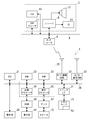
図1は、この発明の実施形態が適用される端末装置である携帯電話機1およびオーディオシステム3の構成を示す図である。
携帯電話機1はいわゆるスマートフォンと言われる機種が好適である。携帯電話機(スマートフォン)1は、携帯通信網である3G/4G通信機能を有するとともに、無線LAN(Wi-Fi)通信機能を有しており、Wi-Fiルータ5を介してネットワーク6に接続される。ネットワーク6には、オーディオシステム3のマスタ装置となるレシーバ4も接続されている。レシーバ4は、音・映像信号の受信、送信などを行う。
携帯電話機1は、アプリケーションプログラム(アプリ)であるオーディオシステムコントローラプログラム50(以下、単にプログラム50とする)を起動することにより、図2に示すオーディオシステムコントローラ100(以下、単にコントローラ100とする)として機能し、ユーザの操作に応じて、ネットワーク6経由でレシーバ4を制御する。その制御機能は、入力ソースの選択、電源のオン/オフ、ボリューム(音量)値の上下などである。コントローラ100におけるボリューム値の制御は、コントローラ100に表示されるスライダ418に対するスライド操作(ドラック操作)によって行われる。
オーディオシステム3は、マスタ装置となるレシーバ4にスピーカ12及びテレビ(TV)13が接続された構成である。レシーバ4、セットトップボックス(STB)10、及びDVDプレーヤ11は、ネットワーク6に接続されている。レシーバ4は、複数のオーディオソースからいずれかを選択し、そのオーディオソースの再生(受信)映像をテレビ13に出力するとともに、再生(受信)映像をスピーカ12に出力(送信)する。オーディオソースの選択、ボリューム値の上下等は、レシーバ4の操作パネルを直接操作して行うことが可能であるが、上述のように、携帯電話機1を用いて行うことも可能である。なお、オーディオシステム3の構成は図示のものに限定されない。
次に、プログラム50が実行される携帯電話機1の構成を説明する。携帯電話機1は、バス26上に、制御部20、操作部30、メディアインタフェース31、Wi-Fi通信回路32および3G/4G通信回路33を有している。制御部20は、CPU21、ROM(フラッシュメモリ)22、RAM23、画像プロセッサ24および音声プロセッサ25を含んでいる。画像プロセッサ24には、ビデオRAM(VRAM)40が接続され、VRAM40には表示部41が接続されている。表示部41は、液晶のディスプレイを含み、待ち受け画面や電話番号などを表示する。また、後述のコントローラ100の画面も表示部41に表示される。音声プロセッサ25には、D/Aコンバータを含むアンプ42が接続され、アンプ42にはスピーカ16が接続されている。
画像プロセッサ24は、待ち受け画面や電話番号等などの種々の映像を生成するGPU(Graphics Processing Unit,グラフィックス・プロセッシング・ユニット)を備えている。画像プロセッサ24は、プログラム50が起動された場合には、CPU21の指示に従ってオーディオシステムコントローラの画像を生成し、これをVRAM40上に展開する。VRAM40上に展開された画像は表示部41に表示される。
音声プロセッサ25は、通話音声をエンコード/デコードするDSP(Digital Signal Processor:デジタル・シグナル・プロセッサ)を有している。音声プロセッサ25は、デコード/生成した音声をアンプ42に出力する。アンプ42は、この音声信号を増幅してスピーカ16に出力する。
Wi-Fi通信回路32は、Wi-Fiルータ5との間でIEEE802.11g規格の無線通信を行い、レシーバ4などのネットワーク6上の機器とデータやメッセージの送受信を行う。レシーバ4との間は、DLNA(登録商標;Digital Living Network Alliance)に類して規定されたフォーマットでメッセージを交換する。3G/4G通信回路33は、携帯電話通信網を介して、音声通話およびデータ通信を行う。データ通信によってアプリケーションプログラムのダウンロードが行われる。なお、アプリケーションプログラムは、3G/4G通信でダウンロードするのみならず、Wi-Fi通信やUSBなどのインタフェース経由で取得するようにしてもよい。
操作部30は、表示部41上に形成されたタッチパネルを含み、タッチパネルに対するタッチ操作やスライド操作等を検出する。メディアインタフェース31にはメモリカード15が接続される。メモリカード15は、たとえばマイクロSDカードである。3G/4G通信回路33によってサーバからダウンロードされたアプリケーションプログラムは、メモリカード15またはROM22に保存される。この携帯電話機1では、図1に示すように、プログラム50(アプリケーションプログラム)がメモリカード15に保存されている。
プログラム50は、プログラム本体に加えてプログラムの実行に必要なデータを含んでいる。プログラムの実行に必要なデータは、たとえば、コマンドテーブルなどである。コマンドテーブルは、オーディオシステム3に対する制御内容とその制御内容を表すコマンドを対応づけたテーブルである。コマンドテーブルには、AVレシーバの電源をオン/オフする、音量を上げる/下げる、入力ソースとしてDVDプレーヤ/STBを選択する、などのコマンドが記憶されている。なお、オーディオシステム3に対する制御内容を表すコマンドは、コマンド記憶場所に対応づけられていてもよい。
ROM22には、この携帯電話機1の通話やアプリケーションプログラムを実行するための基本プログラムが記憶されている。また、ROM22はフラッシュメモリであり、基本プログラムのほか、ダウンロードされたアプリケーションプログラムなどを記憶することも可能である。RAM23には、CPU20がプログラム50を実行する際に使用されるワークエリアが設定される。ワークエリアには、たとえば、各種データのタイマエリア、カウンタエリア、フラグエリアなどが設けられる。
携帯電話機1は、メモリカード15に保存されているプログラム50との協働によって、図2に示すようなコントローラ100を構成し、Wi-Fi経由でレシーバ4にコマンドメッセージを送信してレシーバ4を制御する。
図2の機能ブロック図を参照して、携帯電話機1(ハードウェア)にプログラム50が読み込まれることによって実現されるコントローラ100について説明する。コントローラ100は、操作画面表示部110、操作検出部120、メッセージ編集送信部130および状態取得部140を有している。
操作画面表示部110は、制御部20、VRAM40、表示部41およびプログラム50の協働によって実現され、携帯電話機1の表示部41に、各種の操作画面を表示する。操作画面表示部110は、本発明の操作画面表示部に相当する。
操作検出部120は、制御部20、操作部30およびプログラム50の協働によって実現される。操作検出部120は、表示部41に表示された操作画面に対する操作、たとえば、タッチ操作やスライド操作を検出する。操作検出部120で検出された操作情報は、操作画面表示部110、メッセージ編集送信部130などに入力される。操作検出部120は、本発明の操作検出部に相当する。
メッセージ編集送信部130は、制御部20、Wi-Fi通信回路32およびプログラム50の協働によって実現される。メッセージ編集送信部130は、操作検出部120から入力された操作情報に基づき、その操作情報(制御内容)に対応するコマンドをコマンドテーブルから読み出してコマンドメッセージを編集する。そして、そのコマンドメッセージをレシーバ4に送信する。メッセージ編集送信部130は、本発明のパラメータ更新部に相当する。
状態取得部140は、制御部20、Wi-Fi通信回路32およびプログラム50の協働によって実現される。状態取得部140は、レシーバ4に対して問い合わせを行い、レシーバ4の動作状態を取得する。動作状態とは、そのとき選択されている入力ソース、ボリューム値などである。この問い合わせは、コントローラ100の起動時またはレシーバ4の起動時、および、適宜(たとえば5秒毎、コマンドメッセージの送信直後など)に行われる。取得したボリューム値は、図3に示す操作画面400の表示に反映される。
図3は、操作画面表示部110によって表示される操作画面400の例を示す図である。この操作画面400は表示部41に表示される。ユーザは、表示部41に重ねられたタッチパネル(操作部30)で操作画面400を操作することができる。図3は、再生制御画面を示している。再生制御画面では、ユーザは、選択されたオーディオソースのスタート/停止、および、ボリューム値の上下のコントロールをすることが可能である。この図において、操作画面400の中央にウィンドウ410が形成されている。ウィンドウ410内には、選択されたオーディオソースに対応付けられた画像411、再生ボタン群412、棒グラフ表示エリア414、棒グラフ415、スライダ表示エリア417、及びスライダ418が表示されている。
タッチパネル(操作部30)には、表示部41上のタッチ操作やスライド操作(タッチしたまま移動する操作)の位置を把握するため、座標軸が設定されている。本実施形態では、タッチパネル(操作部30)の図示左上を原点とし、原点から図示右方にX軸、原点から図示下方にY軸をそれぞれ設定している。タッチ操作やスライド操作は、手指Fがタッチパネル(操作部30)に接触している位置の座標の変化として把握される。なお、以下の説明では、図3に図示した姿勢の方向(上下左右)で表示部41内の部品の位置を説明する。
再生ボタン群412は、再生・停止ボタン、早送りボタン、巻き戻しボタンを有している。各ボタンのタッチ操作が操作検出部120によって検出され、その操作情報がメッセージ編集送信部130に伝達される。メッセージ編集送信部130は、再生ボタンがタップされると、そのときの再生状態に応じて再生開始コマンドまたは停止コマンドがレシーバ4に送信される。また、早送りボタンがタップ(タッチ)されると、そのときの再生状態に応じて次曲コマンドまたは早送りコマンドがレシーバ4に送信される。また、巻き戻しボタンがタップされると、そのときの再生状態に応じて前曲コマンドまたは巻き戻しコマンドが送信される。
棒グラフ表示エリア414には、現在のボリューム値に対応した長さの棒グラフ415が表示される。棒グラフ表示エリア414は、X軸方向に伸びている。棒グラフ表示エリア414は、本発明のパラメータ表示部に相当する。
棒グラフ415は、ボリューム値を表すグラフである。棒グラフ415は、棒グラフ表示エリア414の左端を原点として、ボリューム値が上昇するのに応じて右方(X軸の正の方向)に伸び、ボリューム値が下降するのに応じて左方(X軸の負の方向)に縮む。ボリューム値は、棒グラフ415の右端の位置によって表される。つまり、ボリューム値は、棒グラフ415の左端から右端までの長さによって表される。棒グラフ415の左端を第1端部415A、棒グラフ415の右端を第2端部415Bとする。
スライダ表示エリア417は、棒グラフ表示エリア414の全体をカバーしており、そのときのボリューム値またはユーザの操作に応じた位置にスライダ418が表示される。
スライダ418は、スライド操作によってボリューム値を上昇及び下降させるためのものである。図3では、スライダ418は、棒グラフ415の第2端部に重ねて配置されている。ユーザのスライド操作により、スライダ418をX軸に沿って右方及び左方に移動させることが可能である。スライダ418を右方に移動させるとボリューム値は上昇し、スライダ418を左方に移動させるとボリューム値は下降する。スライダ418の位置は、座標で把握される。スライダ418の左右方向の移動量は、X座標の変位量として把握される。ユーザがスライダ418を操作している間、スライダ418の周囲には、輪郭線418Aが表示される。輪郭線418Aは、スライダ418が操作状態である旨、および、スライダ418の位置を明確にするために表示される。スライダ418は、本発明の被操作部に相当する。
スライダ418がユーザによって右方または左方にスライド操作されると、そのスライド操作の操作情報が操作検出部120によって検出され、メッセージ編集送信部130、及び操作画面表示部110に伝達される。メッセージ編集送信部130は、ボリューム値更新のコマンドメッセージを編集してレシーバ4に送信する。操作画面表示部110は、操作内容に応じて、棒グラフ表示エリア414、及びスライダ表示エリア417の表示内容を更新する。
スライダ418が棒グラフ表示エリア414の左端に位置する場合、ボリューム値は最小となる。スライダ418が棒グラフ表示エリア414の右端に位置する場合、ボリューム値は最大となる。ボリューム値は、最小値と最大値の間で段階的に変更可能である。最小値から最大値まで、例えば、100段階に変更可能である。ボリューム値の1段階(1カウント)は、スライダ418の左右方向の移動量、つまりX座標の変位量に関連付けられている。ボリューム値は、操作対象のオーディオ機器(たとえばレシーバ4)において、1段階(1カウント)で、例えば、0.5dBずつ変更される。例えば、スライダ418を現状の位置からボリューム上昇方向(右方)に5カウント移動させると、ボリューム値は2.5dB上昇する。また、スライダ418を現状の位置からボリューム下降方向(左方)に10カウント移動させると、ボリューム値は5.0dB下降する。
図4、図5及び図6を参照して、本実施形態のコントローラ100によってボリューム値を上昇及び下降させる制御について説明する。スライダ418がボリューム下降方向(左方)に操作された場合、または、ボリューム上昇方向(右方)にゆっくり(閾値以下)操作された場合、ボリューム値、すなわち棒グラフ415の第2端部415B(右端)はスライダ418に完全に追従して同じ位置になる。スライダ418が、ボリューム上昇方向(右方)に閾値以上の速さで操作された場合、ボリューム値は、スライダ418に遅れて追従する。
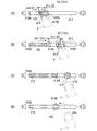
まず、図4を参照して、ボリューム値を上昇させる制御について説明する。図4では、スライダ418をX軸に沿って右方にスライド操作して、ボリューム値を上昇させる操作の例を示している。ボリューム上昇方向(X軸に沿って右方)は、本発明の第1方向に相当する。
図4(A)、(B)は、ユーザが手指Fでスライダ418をボリューム上昇方向(右方)にスライド操作し、それに伴って、棒グラフ415の右端が、ボリューム上昇方向(右方)に伸びている状態を示している。スライダ418のボリューム上昇方向への移動量をVs1とする。また、棒グラフ415の右端のボリューム上昇方向への位置の変化率、すなわち棒グラフ415のボリューム上昇方向への単位時間当たり(たとえば1秒当たり)の移動量をVg1とする。なお、スライダ418の移動量Vs1は、単位時間の移動量ではなく、ユーザの指の位置に追従(一致)した位置に表示されたスライダ418の位置と、ボリューム値を表す棒グラフ415の右端の位置とのX座標値の差(距離)を表す値である。スライダ418のボリューム上昇方向への移動量Vs1は、本発明の第1方向への操作量に相当する。
棒グラフ415の右端は、スライダ418の位置が棒グラフ415の右端よりも右に位置する場合、ボリューム上昇方向へ移動速度Vg1でその位置を変化させる。棒グラフ415のボリューム上昇方向への移動速度Vg1は、例えば、単位時間あたりに棒グラフ415の右端が伸びるカウント数で表される。例えば、棒グラフ415の右端が毎秒3カウント伸びる場合は、Vg1=3カウント/秒と表すことができ、毎秒5カウント移動する場合は、Vg1=5カウント/秒と表すことができる。
棒グラフ415のボリューム上昇方向への移動速度Vg1すなわちボリューム値の上昇率には、第1閾値Vthが設定されている。第1閾値Vthは、例えば、5カウント/秒である。図4(A)では、スライダ418の移動量Vs1はV1であり、V1は第1閾値Vth以下である(Vs1=V1≦Vth)。つまり、スライダ418の移動量Vs1は、棒グラフ415の右端が単位時間当たりに移動する最大移動距離の値(Vth)以下である。この場合、棒グラフ415の右端の移動速度Vg1を、スライダ418の移動量Vs1と等しくする(Vg1=Vs1=V1)。このため、スライダ418は、ユーザのスライド操作に伴ってボリューム上昇方向へ移動し、棒グラフ415もスライダ418の移動に伴ってボリューム上昇方向へ伸びる。よって、棒グラフ415の右端(第2端部415B)は、スライダ418に重なった状態でボリューム上昇方向へ移動する。また、ボリューム値は、スライダ418及び棒グラフ415の移動速度に対応して上昇する。つまり、スライダ418のボリューム上昇方向への移動量Vs1(棒グラフ415の右端とスライダ418とのズレ)が、ボリューム値の上昇率の第1閾値Vth以下の場合は、ボリューム値は、スライダ418の動きに合わせて上昇する。
図4(B)は、ユーザが手指Fでスライダ418をボリューム上昇方向(右方)に速い速度でスライド操作し、棒グラフ415の右端が、スライダ418の移動速度よりも遅い移動速度でボリューム上昇方向(右方)に伸びている状態を示している。また、同図の状態は、ユーザが手指Fで棒グラフ表示エリア414内の棒グラフ415の右端より右方に離れた位置にタッチした場合にも生じる。すなわち、スライダ418は、スライダ表示エリア417内の手指Fのタッチに完全に追従する。
図4(B)では、スライダ418の移動量Vs1はV2であり、V2は第1閾値Vthより大きい(Vs1=V2>Vth)。この場合、棒グラフ415の右端の移動速度Vg1は、スライダ418の移動量Vs1に完全に追従せず、第1閾値Vthと等しくなる(Vg1=Vth)。すなわち、スライダ418は、ユーザのスライド操作に伴ってボリューム上昇方向へ移動するが、棒グラフ415は、スライダ418の移動速度よりも小さい速度でボリューム上昇方向へ伸びる。このため、棒グラフ415の右端は、スライダ418に重ならずに離隔した状態でボリューム上昇方向へ移動する。また、ボリューム値は、スライダ418ではなく、棒グラフ415の移動速度に対応して上昇する。
つまり、スライダ418のボリューム上昇方向への移動量Vs1が第1閾値Vthを超えている場合は、ボリューム値は、スライダ418ではなく、棒グラフ415の動きに合わせて上昇する。このため、スライダ418をボリューム上昇側に不用意に大きくスライドさせてしまった場合でも、ボリューム値をゆっくりと上昇させることができる。よって、ボリューム値が短時間で大きく上昇して、突然大音量になることを抑制することができる。ユーザがスライダ418を図4(B)に示す位置に停止させてタッチ操作を維持した場合、棒グラフ415(ボリューム値)は、第1しきい値Vthの上昇率で徐々にスライダ418の位置に追い付いてくる。
図4(C)は、ユーザがスライダ418から手指を離し、操作を終了した瞬間の状態を示している。ユーザがスライド操作を終了すると、ボリューム値の制御、すなわち、棒グラフ415の伸縮制御は終了する。ボリューム値は、スライダ418の操作を停止した時点において、棒グラフ415の右端が達した位置に対応するボリューム値で確定する。
図4(D)は、図4(C)の状態の直後であり、スライダ418が棒グラフ415の右端(第2端部415B)に重なる位置に移動した状態を示している。図4(C)で説明したように、スライダ418の操作を終了(解除)すると、ボリューム値は、棒グラフ415の右端(第2端部415B)が達した位置に対応するボリューム値で確定する。スライダ418は、確定したボリューム値に対応するように、棒グラフ415の右端(第2端部415B)に重なる位置に僅かな時間で移動する。
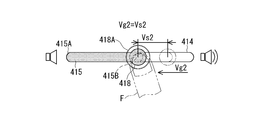
次に、図5を参照して、ボリューム値を下降させる制御について説明する。図5では、スライダ418をX軸に沿って左方(第1方向と反対方向、以下、第2方向ともいう)にスライド操作して、ボリューム値を下降させる操作の例を示している。
図5は、ユーザが手指Fでスライダ418をボリューム下降方向(第2方向)にスライド操作し、それに伴って、棒グラフ415の右端が、ボリューム下降方向(第2方向)に縮んでいく状態を示している。スライダ418のボリューム下降方向への移動量をVs2とする。また、棒グラフ415の右端のボリューム下降方向への単位時間当たり(たとえば1秒当たり)の移動量をVg2とする。なお、スライダ418の移動量Vs2は、単位時間の移動量ではなく、ユーザの指の位置に追従(一致)した位置に表示されたスライダ418の位置と、ボリューム値を表す棒グラフ415の右端の位置とのX座標値の差(距離)を表す値である。
スライダ418のボリューム下降方向(第2方向)への移動量Vs2には、閾値は設定されていない。このため、スライダ418の移動量Vs2の大きさに関わらず、棒グラフ415の右端の移動速度Vg2は、スライダ418の移動量Vs2と等しくなる(Vg2=Vs2)。すなわち、スライダ418は、ユーザのスライド操作に伴ってボリューム下降方向へ移動し、棒グラフ415もスライダ418の移動に伴ってボリューム下降方向へ縮む。このため、棒グラフ415の右端(第2端部415B)は、スライダ418に重なった状態でボリューム下降方向へ移動する。また、ボリューム値は、棒グラフ415の移動速度に対応して下降する。
つまり、スライダ418のボリューム下降方向への移動量Vs2(棒グラフ415の右端とスライダ418とのズレ)の大小に関わらず、ボリューム値は、スライダ418の動きに合わせて下降する。このため、ボリューム値を素早く下降させることが可能となる。
図6のフローチャートを参照して、ボリューム値を上昇又は下降させる場合における、本実施形態のコントローラ100の動作を説明する。
コントローラ100の動作がスタートすると(スタート)、スライダ418に対するスライド操作が行われたかどうか判定する(S1)。スライダ418に対するスライド操作が検出されると(S1でYES)、操作検出部120で検出された操作情報は、操作画面表示部110、及びメッセージ編集送信部130に入力される。操作画面表示部110は、スライダ418に対する操作内容に応じて、スライダ418の表示位置を更新する(S2)。ユーザがスライダ418を操作している間、スライダ418の周囲には、輪郭線418Aが表示される。操作検出部120は、スライダ418がボリューム上昇方向(第1方向)へ操作されたかどうか判定する(S3)。
操作検出部120は、スライダ418がボリューム上昇方向へ操作されたと判定した場合(S3でYES)、スライダ418への操作内容に基づいて、スライダ418の第1方向への移動量Vs1を検出する。また、移動量Vs1が、所定の第1閾値Vth以下であるか否かを判定する(S4)。
移動量Vs1が第1閾値Vth以下である場合(S4でYES)、メッセージ編集送信部130は、スライダ418の移動量Vs1に対応したボリューム値上昇に関するコマンドメッセージを編集し、そのコマンドメッセージをレシーバ4に送信する(S5)。操作画面表示部110は、棒グラフ415の移動速度Vg1をスライダ418の移動量Vs1に対応させて、棒グラフ415の表示内容を更新する(S6)。その後、ステップ1(S1)に戻る。
一方、スライダ418の移動量Vs1が第1閾値Vthより大きい場合(S4でNO)、メッセージ編集送信部130は、スライダ418の移動量Vs1ではなく、所定の第1閾値Vthに対応したボリューム値上昇に関するコマンドメッセージを編集し、そのコマンドメッセージをレシーバ4に送信する(S7)。操作画面表示部110は、棒グラフ415の移動速度Vg1を第1閾値Vthに対応させて、棒グラフ415の表示内容を更新する(S8)。その後、ステップ1(S1)に戻る。
また、操作検出部120は、ステップ3で、スライダ418がボリューム上昇方向へ操作されなかったと判定した場合(S3でNo)、スライダ418への操作内容に基づいて、スライダ418の第1方向と反対方向への移動量Vs2を検出する。メッセージ編集送信部130は、スライダ418の移動量Vs2に対応したボリューム値の下降に関するコマンドメッセージを編集し、そのコマンドメッセージをレシーバ4に送信する(S9)。操作画面表示部110は、棒グラフ415の移動速度Vg2をスライダ418の移動量Vs2に対応させて、棒グラフ415の表示内容を更新する(S10)。その後、ステップ1(S1)に戻る。
また、ステップ1で、スライダ418に対するスライド操作が行われなかったと判定した場合(S1でNo)、スライダ418を棒グラフ415の右端(第2端部415B)に一致させた状態として(S11)、再度ステップ1に戻る。
なお、図3~図6の実施形態では、ボリュームを上昇させる場合のみ閾値Vthを設けてゆっくり上昇させているが、ボリュームを下降させる場合にも閾値を設けてゆっくり下降させるようにしてもよい。
次に、図7及び図8を参照して、本実施形態のコントローラ100によってボリューム値を微調整させる制御について説明する。コントローラ100では、スライダ418をタッチ操作している手指Fを、タッチパネルにタッチしたままスライダ表示エリア417から外れてY軸方向(図示上方)に移動させ、その位置で手指FをX軸方向(図示右方又は図示左方)にスライド操作することにより、ボリューム値を微調整することができる。図7は、手指Fの移動の形態、および、ボリューム値(棒グラフ415)の変化の形態を示している。スライダ418は、X軸方向に沿った仮想線Y0上で、ボリューム上昇方向(第1方向)、及びボリューム下降方向(第2方向)に操作可能である。スライダ418に対するY軸方向(図示上方)は、ボリューム上昇方向(第1方向)、及びボリューム下降方向(第2方向)のいずれとも異なる方向であり、本発明の第3方向に相当する。
尚、この実施形態では、スライダ418をタッチ操作している手指Fを、タッチパネルにタッチしたままスライダ418から外れてY軸方向(図示上方)に移動させた場合に、以下の動作が行われる。スライダ418にタッチ操作せずに、初めからスライダ418から外れた位置にタッチ操作しても、以下の動作は行われない。
図7(A)は、スライダ418に手指Fを接触させた状態を示している。棒グラフ表示エリア414には、上述のようにX軸に平行な仮想線Y0が設定されている。仮想線Y0に対してY軸方向に間隔をおいて、仮想線Y1と仮想線Y5が設定されている。仮想線Y1は、仮想線Y0に対してY軸の負方向に配置され、仮想線Y5は、仮想線Y0に対してY軸の正方向に配置されている。仮想線Y5と仮想線Y1とで挟まれる領域を第1仮想領域AR1とする。第1仮想領域AR1は、本発明の通常操作領域に相当する。
仮想線Y1の上方には、X軸に平行、かつY軸方向に等間隔をおいた仮想線Y2、Y3、及びY4が設定されている。仮想線Y2、Y3、及びY4は、この順番で設定されている。仮想線Y1及びY2の間には、第2仮想領域AR2が設定されている。同様に、仮想線Y2及びY3の間には、第3仮想領域AR3が設定され、仮想線Y3及びY4の間には、第4仮想領域AR4が設定されている。第2仮想領域AR2、第3仮想領域AR3、及び第4仮想領域AR4は、それぞれ本発明の微調整領域に相当する。
図7(B)は、図7(A)に引き続いて、手指Fをタッチパネル(操作部30)に接触させた状態のまま、手指Fをスライダ418から第4仮想領域AR4までY軸方向にスライド操作した状態を示している。手指FをY軸方向にスライド操作してもスライダ418はY軸方向には移動しない。図7(B)では、手指Fが第4仮想領域AR4に接触している位置を接触位置419として仮想線で示している。接触位置419は、表示部41には表示されないが、図形等で表示されるようにしてもよい。
図7(C)は、図7(B)に引き続いて、手指F(接触位置419)を第4仮想領域AR4においてX軸方向(図示右方又は図示左方)にスライド操作することにより、ボリューム値を微調整する状態を示している。第4仮想領域AR4で手指F(接触位置419)をX軸方向にスライド操作すると、これに対応してスライダ418もX軸方向に移動する。
第4仮想領域AR4における手指F(接触位置419)の位置のX軸方向の移動量を移動量Vf4とし、これに対応するスライダ418の位置の移動量を縮小移動量Vs3とする。移動量Vf4と縮小移動量Vs3との間には、所定の縮小率が予め設定されている。例えば、移動量Vf4:縮小移動量Vs3=4:1のような縮小率(縮小率0.25倍)が設定されている。この場合、手指F(接触位置419)の移動量Vf4に対してスライダ418の縮小移動量Vs3は、1/4となる。
また、第3仮想領域AR3における手指F(接触位置419)の移動量を移動量Vf3とすると、例えば、移動量Vf3:縮小移動量Vs3=3:1のような縮小率(縮小率0.33倍)が設定されている。この場合、手指F(接触位置419)の移動量Vf3に対してスライダ418の縮小移動量Vs3は、1/3となる。
同様に、第2仮想領域AR2における手指F(接触位置419)の移動量を移動量Vf2とすると、例えば、移動量Vf2:縮小移動量Vs3=2:1のような縮小率(縮小率0.5倍)が設定されている。この場合、手指F(接触位置419)の移動量Vf2に対してスライダ418の縮小移動量Vs3は、1/2となる。
このように、微調整領域である仮想領域AR4、AR3及びAR2において手指F(接触位置419)でスライド操作することにより、スライダ418は、手指F(接触位置419)の移動量に対して所定の縮小率で縮小された縮小移動量で操作される。このため、手指F(接触位置419)を大きくスライド操作させながら、スライダ418の位置を微調整することが可能となり、ボリューム値の微調整が容易となる。
尚、本発明の通常操作領域に相当する第1仮想領域AR1では、移動量Vf1:縮小移動量Vs3=1:1のような縮小率(縮小率1.0倍)が設定されている。この場合、手指F(接触位置419)の移動量Vf2に対してスライダ418の縮小移動量Vs3は、1であり、変化しない。これは、第1仮想領域AR1はスライダ418に近く、この領域でスライド操作すると手指Fがスライダ418に接触することがあるためである。スライダ418に近い領域では、スライダ418を直接スライド操作する場合と同じ動作とすることにより、ユーザが意図しない動作になることを抑制することができる。
図8のフローチャートを参照して、ボリューム値を微調整する場合における、本実施形態のコントローラ100の動作を説明する。
コントローラ100の動作がスタートすると(スタート)、操作検出部120は、スライダ418から第3方向(Y軸方向)に離れた領域での移動操作が、第4仮想領域AR4で行われているかどうか判定する(S32)。
移動操作が第4仮想領域AR4で行われていると判定されると(S32でYES)、操作検出部120は、予め第4仮想領域AR4に関連付けられている所定の縮小率(移動量Vf4:縮小移動量Vs3=4:1)を選択する(S32)。そして、操作検出部120は、移動量Vf4と所定の縮小率(Vf4:Vs3=4:1)から、縮小移動量Vs3=Vf4/4を算出する(S33)。操作検出部120で取得された操作情報は、操作画面表示部110、及びメッセージ編集送信部130に入力される。操作画面表示部110は、算出された縮小移動量Vs3に応じて、スライダ418の表示位置を更新する(S34)。
メッセージ編集送信部130は、スライダ418の縮小移動量Vs3に対応したボリューム値に関するコマンドメッセージを編集し、そのコマンドメッセージをレシーバ4に送信する(S35)。操作画面表示部110は、スライダ418の縮小移動量Vs3に対応させて棒グラフ415の表示内容を更新し(S36)、スライド操作が解除されると、コントローラ100の動作を終了する(終了)。
一方、移動操作が第4仮想領域AR4で行われていない場合(S31でNO)、操作検出部120は、第3操作が第3仮想領域AR3で行われているかどうか判定する(S37)。
移動操作が第3仮想領域AR3で行われていると判定されると(S37でYES)、操作検出部120は、予め第3仮想領域AR3に関連付けられている所定の縮小率(移動量Vf3:縮小移動量Vs3=3:1)を選択する(S38)。そして、操作検出部120は、移動量Vf3と所定の縮小率(Vf3:Vs3=3:1)から、縮小移動量Vs3=Vf3/3を算出する(S39)。続いて、ステップ34(S34)、ステップ35(S35)、及びステップ36(S36)が実行されるが、実行される内容は上述した内容と同様であるため、詳しい説明は省略する。スライド操作が解除されると、コントローラ100の動作を終了する(終了)。
また、移動操作が第3仮想領域AR3で行われていない場合(S37でNO)、操作検出部120は、移動操作が第2仮想領域AR2で行われているかどうか判定する(S40)。
移動操作が第2仮想領域AR2で行われていると判定されると(S40でYES)、操作検出部120は、予め第2仮想領域AR2に関連付けられている所定の縮小率(移動量Vf2:縮小移動量Vs3=2:1)を選択する(S41)。そして、操作検出部120は、移動量Vf2と所定の縮小率(Vf2:Vs3=2:1)から、縮小移動量Vs3=Vf2/2を算出する(S42)。続いて、ステップ34(S34)、ステップ35(S35)、及びステップ36(S36)が実行されるが、実行される内容は上述した内容と同様であるため、詳しい説明は省略する。スライド操作が解除されると、コントローラ100の動作を終了する(終了)。
また、移動操作が第2仮想領域AR2で行われていない場合(S40でNO)、操作検出部120は、移動操作が第1仮想領域AR1で行われているかどうか判定する(S43)。
移動操作が第1仮想領域AR1で行われていると判定されると(S43でYES)、操作検出部120は、予め第1仮想領域AR1に関連付けられている所定の縮小率(移動量Vf1:縮小移動量Vs3=1:1)を選択する(S44)。そして、操作検出部120は、移動量Vf1と所定の縮小率(Vf1:Vs3=1:1)から、縮小移動量Vs3=Vf1/1を算出する(S45)。続いて、ステップ34(S34)、ステップ35(S35)、及びステップ36(S36)が実行されるが、実行される内容は上述した内容と同様であるため、詳しい説明は省略する。スライド操作が解除されると、コントローラ100の動作を終了する(終了)。移動操作が第1仮想領域AR1で行われていないと判定された場合は(S43でNO)、ステップ31(S31)に戻る。
図7、図8の実施形態では、手指Fが棒グラフ表示エリア414から上方(Y軸負方向)に仮想領域を設定した例を説明したが、棒グラフ表示エリア414の下方に仮想領域を設定してもよい。また、縮小率の異なる3つの仮想領域を重ねているが、仮想領域の数は3に限定されない(1つであってもよい)。また、複数の仮想領域毎に変化率を変えるのでなく、手指Fの位置と棒グラフ表示エリア414とのY軸方向の距離に応じて無段階的に変化率を算出してもよい。
図7、図8の実施形態では、微調整処理は、スライダ418にタッチした手指Fをタッチパネルから離さないままY方向に移動した場合に実行される。スライダ418にタッチしていなくても、何らかの操作とともに手指Fを棒グラフ415からY方向に離れた位置にタッチした場合に微調整処理が実行されるようにしてもよい。
図4から図6のボリューム値がスライダ418の操作に遅れて追従する機能と、図7、図8のボリューム微調整機能を組み合わせてもよい。
上記実施形態では、本発明が適用される端末装置として携帯電話機1を例示しているが、端末装置は携帯電話機1に限定されない。たとえば、タブレット、専用のコントローラ端末装置であってもよい。
この実施形態では、ボリューム値を例に上げたが、連続して滑らかに上昇/下降させるべきパラメータであれば、他のどのようなパラメータに適用することも可能である。
本出願は、2015年6月16日付で出願された日本国特許出願である特願2015-121464に基づくものであり、その優先権を享受し、その内容はここに参照として取り込まれる。
1: 携帯電話機
4: レシーバ
15: メモリカード
20: 制御部
41: 表示部
50: オーディオシステムコントローラプログラム
100: オーディオシステムコントローラ
415: 棒グラフ
418: スライダ
4: レシーバ
15: メモリカード
20: 制御部
41: 表示部
50: オーディオシステムコントローラプログラム
100: オーディオシステムコントローラ
415: 棒グラフ
418: スライダ
Claims (16)
- 被操作部と、
前記被操作部に対する操作を検出する操作検出部と、
前記被操作部に対する操作に応じて前記被操作部の表示位置を更新する操作画面表示部と、
前記被操作部に対する操作に応じて、被制御機器に対するパラメータの値を更新するパラメータ更新部と、
を備え、
前記パラメータ更新部は、
前記被操作部に対する操作量が、所定の閾値以下の場合、前記パラメータをその操作量に応じて更新し、
前記操作量が、前記閾値を超える場合、前記パラメータを前記閾値の値に応じて更新し、
前記操作検出部が前記被操作部の操作の解除を検出した場合、前記パラメータの更新処理を停止し、
前記操作画面表示部は、
前記パラメータの更新処理が停止された場合、前記被操作部の表示位置をその時点の前記パラメータの値に応じた表示位置に更新する、
パラメータ制御装置。 - 前記パラメータ更新部は、
前記被操作部に対する第1方向への操作量が所定の閾値以下の場合、または、前記被操作部に対する操作が前記第1方向と反対方向であった場合、前記パラメータをその操作量に応じて更新し、
前記被操作部に対する第1方向への操作量が前記閾値を超える場合、前記パラメータを前記閾値の値に応じて更新する、
請求項1に記載のパラメータ制御装置。 - 固定された第1端部およびパラメータの値に応じて移動する第2端部を有し、前記パラメータの値に応じて画像を表示するパラメータ表示部をさらに備え、
前記操作画面表示部は、前記被操作部が操作されていないとき、前記被操作部を前記パラメータ表示部の第2端部に一致する位置に表示する、
請求項1または請求項2に記載のパラメータ制御装置。 - 前記パラメータ表示部は、前記パラメータの値に応じて伸縮する棒グラフ状の画像を表示する、
請求項3に記載のパラメータ制御装置。 - 前記被操作部が操作されたとき、
前記操作画面表示部は、前記被操作部の表示を前記操作量に対応する前記第2端部から離れた位置に更新し、
前記パラメータ表示部は、前記棒グラフを前記パラメータの変化率に対応する変化率で伸縮して、前記第2端部を移動させる、
請求項4に記載のパラメータ制御装置。 - 仮想の線分上を移動可能な被操作部と、
所定のパラメータを表示するパラメータ表示部と、
前記線分に沿った移動操作を検出する操作検出部と、
前記移動操作に応じて、前記被操作部の位置を更新するとともに、前記被操作部の表示位置に応じて前記パラメータ表示部の表示内容を更新する操作画面表示部と、
を備え、
前記操作検出部は、前記線分の向きと異なる方向を第3方向とし、前記線分から前記第3方向に離れた領域において前記線分に沿った移動操作を検出したとき、その操作位置と前記線分との前記第3方向における距離を検出し、
この第3方向の距離に応じて前記移動操作の縮小率を決定し、
前記操作画面表示部は、前記移動操作の移動量を前記縮小率で縮小した値で、前記被操作部の表示位置を更新するとともに前記パラメータ表示部の表示内容を更新する、
パラメータ制御装置。 - 前記線分から前記第3方向に離れた距離が所定の距離未満である領域を通常操作領域とし、前記線分から前記第3方向に離れた距離が所定の距離以上である領域を微調整領域として、
前記通常操作領域において移動操作が検出された場合、前記縮小率を1とし、
前記微調整領域において移動操作が検出された場合、前記縮小率を1より小さい値とする、
請求項6に記載のパラメータ制御装置。 - 前記通常操作領域から前記微調整領域に操作位置を移動させる操作が検出された場合、
前記操作画面表示部は、その後の微調整領域における移動操作に対して前記縮小率を適用する、
請求項7に記載のパラメータ制御装置。 - 前記微調整領域は、前記第3方向の距離に応じて複数の部分領域に分割されており、前記各部分領域には、それぞれ異なる縮小率が設定されている、
請求項7または請求項8に記載のパラメータ制御装置。 - 被操作部が設けられた携帯端末装置の制御部を、
前記被操作部に対する操作を検出する操作検出手段、前記被操作部に対する操作に応じて前記被操作部の表示位置を更新する操作画面表示手段、及び、前記被操作部に対する操作に応じて、被制御機器に対するパラメータの値を更新するパラメータ更新手段、
として機能させるパラメータ制御プログラムであって、
前記パラメータ更新手段は、
前記被操作部に対する操作量が、所定の閾値以下の場合、前記パラメータをその操作量に応じて更新し、
前記操作量が、前記閾値を超える場合、前記パラメータを前記閾値の値に応じて更新し、
前記操作検出手段が前記被操作部の操作の解除を検出した場合、前記パラメータの更新処理を停止し、
前記操作画面表示手段は、
前記パラメータの更新処理が停止された場合、前記被操作部の表示位置をその時点の前記パラメータの値に応じた表示位置に更新する、
パラメータ制御プログラム。 - 仮想の線分上を移動可能な被操作部が設けられた携帯端末装置の制御部を、
所定のパラメータを表示するパラメータ表示手段、前記線分に沿った移動操作を検出する操作検出手段、前記移動操作に応じて、前記被操作部の位置を更新するとともに、前記被操作部の表示位置に応じて前記パラメータ表示手段の表示内容を更新する操作画面表示手段、
として機能させるパラメータ制御プログラムであって、
前記操作検出手段は、前記線分の向きと異なる方向を第3方向とし、前記線分から前記第3方向に離れた領域において前記線分に沿った移動操作を検出したとき、その操作位置と前記線分との前記第3方向における距離を検出し、
この第3方向の距離に応じて前記移動操作の縮小率を決定し、
前記操作画面表示手段は、前記移動操作の移動量を前記縮小率で縮小した値で、前記被操作部の表示位置を更新するとともに前記パラメータ表示手段の表示内容を更新する、
パラメータ制御プログラム。 - 仮想の線分上を移動可能な被操作部が設けられた携帯端末装置におけるパラメータ制御方法であって、
前記被操作部に対する操作量を検出し、
検出した前記操作量が、所定の閾値以下の場合、被制御機器に対するパラメータをその操作量に応じて更新する一方で、前記操作量が、前記閾値を超える場合、前記パラメータを前記閾値の値に応じて更新し、
前記被操作部の操作の解除を検出した場合、前記パラメータの値を更新する更新処理を停止し、
前記更新処理が停止された場合、前記被操作部の表示位置をその時点の前記パラメータの値に応じた表示位置に更新する、
パラメータ制御方法。 - 前記被操作部に対する第1方向への操作量が所定の閾値以下の場合、または、前記被操作部に対する操作が前記第1方向と反対方向であった場合、前記パラメータをその操作量に応じて更新し、
前記被操作部に対する第1方向への操作量が前記閾値を超える場合、前記パラメータを前記閾値の値に応じて更新する、
請求項12に記載のパラメータ制御方法。 - 前記携帯端末装置は、固定された第1端部およびパラメータの値に応じて移動する第2端部を有し、前記パラメータの値に応じて画像を表示するパラメータ表示部をさらに備え、
前記被操作部が操作されていないとき、前記被操作部を前記パラメータ表示部の第2端部に一致する位置に表示する、
請求項12または請求項13に記載のパラメータ制御方法。 - 前記パラメータ表示部は、前記パラメータの値に応じて伸縮する棒グラフ状の画像を表示する、
請求項14に記載のパラメータ制御方法。 - 前記被操作部が操作されたとき、
前記被操作部の表示を前記操作量に対応する前記第2端部から離れた位置に更新し、
前記棒グラフを前記パラメータの変化率に対応する変化率で伸縮して、前記第2端部を移動させる、
請求項15に記載のパラメータ制御方法。
Priority Applications (1)
| Application Number | Priority Date | Filing Date | Title |
|---|---|---|---|
| US15/818,077 US10635387B2 (en) | 2015-06-16 | 2017-11-20 | Parameter control device, parameter control program, and parameter control method |
Applications Claiming Priority (2)
| Application Number | Priority Date | Filing Date | Title |
|---|---|---|---|
| JP2015121464A JP6544069B2 (ja) | 2015-06-16 | 2015-06-16 | パラメータ制御装置およびパラメータ制御プログラム |
| JP2015-121464 | 2015-06-16 |
Related Child Applications (1)
| Application Number | Title | Priority Date | Filing Date |
|---|---|---|---|
| US15/818,077 Continuation US10635387B2 (en) | 2015-06-16 | 2017-11-20 | Parameter control device, parameter control program, and parameter control method |
Publications (1)
| Publication Number | Publication Date |
|---|---|
| WO2016204185A1 true WO2016204185A1 (ja) | 2016-12-22 |
Family
ID=57545264
Family Applications (1)
| Application Number | Title | Priority Date | Filing Date |
|---|---|---|---|
| PCT/JP2016/067827 Ceased WO2016204185A1 (ja) | 2015-06-16 | 2016-06-15 | パラメータ制御装置、パラメータ制御プログラムおよびパラメータ制御方法 |
Country Status (3)
| Country | Link |
|---|---|
| US (1) | US10635387B2 (ja) |
| JP (1) | JP6544069B2 (ja) |
| WO (1) | WO2016204185A1 (ja) |
Families Citing this family (11)
| Publication number | Priority date | Publication date | Assignee | Title |
|---|---|---|---|---|
| CN105898033A (zh) * | 2016-03-23 | 2016-08-24 | 青岛海信移动通信技术股份有限公司 | 一种移动通信终端受话音量的调整方法及调整装置 |
| USD846527S1 (en) * | 2016-11-01 | 2019-04-23 | Roli Ltd. | Control block |
| US10915745B2 (en) * | 2018-06-27 | 2021-02-09 | CoinLion LLC. | Communications system |
| CN108920060A (zh) * | 2018-07-06 | 2018-11-30 | 北京微播视界科技有限公司 | 音量的显示方法、装置、终端设备及存储介质 |
| CN109508170A (zh) * | 2018-12-15 | 2019-03-22 | 深圳壹账通智能科技有限公司 | 音量设置方法、装置、计算机设备及存储介质 |
| USD921012S1 (en) * | 2019-09-19 | 2021-06-01 | Keurig Green Mountain, Inc. | Display screen or portion thereof with graphical user interface |
| USD921008S1 (en) * | 2019-09-19 | 2021-06-01 | Keurig Green Mountain, Inc. | Display screen or portion thereof with graphical user interface |
| USD921009S1 (en) * | 2019-09-19 | 2021-06-01 | Keurig Green Mountain, Inc. | Display screen or portion thereof with graphical user interface |
| USD915425S1 (en) * | 2019-09-19 | 2021-04-06 | Keurig Green Mountain, Inc. | Display screen with graphical user interface |
| USD921010S1 (en) * | 2019-09-19 | 2021-06-01 | Keurig Green Mountain, Inc. | Display screen or portion thereof with graphical user interface |
| US12112030B2 (en) | 2019-12-17 | 2024-10-08 | Google Llc | Mapping user inputs in two directions to a single direction for one-handed device interactions with graphical sliders |
Citations (3)
| Publication number | Priority date | Publication date | Assignee | Title |
|---|---|---|---|---|
| JP2011113409A (ja) * | 2009-11-27 | 2011-06-09 | Fujitsu Toshiba Mobile Communications Ltd | 情報処理装置 |
| JP2012252642A (ja) * | 2011-06-06 | 2012-12-20 | Sony Corp | 情報処理装置、情報処理方法、及びプログラム |
| JP2013037556A (ja) * | 2011-08-09 | 2013-02-21 | Casio Comput Co Ltd | 電子機器、及びプログラム |
Family Cites Families (3)
| Publication number | Priority date | Publication date | Assignee | Title |
|---|---|---|---|---|
| KR20100085199A (ko) * | 2006-04-28 | 2010-07-28 | 가부시키가이샤 엔티티 도코모 | 화상 예측 부호화 장치, 화상 예측 부호화 방법, 화상 예측 부호화 프로그램, 화상 예측 복호 장치, 화상 예측 복호 방법 및 화상 예측 복호 프로그램 |
| JP5962152B2 (ja) | 2012-04-02 | 2016-08-03 | ヤマハ株式会社 | パラメータ制御装置、パラメータ制御プログラムおよび端末装置 |
| JP6189622B2 (ja) * | 2013-04-22 | 2017-08-30 | シャープ株式会社 | 入力装置、および、画像表示装置 |
-
2015
- 2015-06-16 JP JP2015121464A patent/JP6544069B2/ja active Active
-
2016
- 2016-06-15 WO PCT/JP2016/067827 patent/WO2016204185A1/ja not_active Ceased
-
2017
- 2017-11-20 US US15/818,077 patent/US10635387B2/en active Active
Patent Citations (3)
| Publication number | Priority date | Publication date | Assignee | Title |
|---|---|---|---|---|
| JP2011113409A (ja) * | 2009-11-27 | 2011-06-09 | Fujitsu Toshiba Mobile Communications Ltd | 情報処理装置 |
| JP2012252642A (ja) * | 2011-06-06 | 2012-12-20 | Sony Corp | 情報処理装置、情報処理方法、及びプログラム |
| JP2013037556A (ja) * | 2011-08-09 | 2013-02-21 | Casio Comput Co Ltd | 電子機器、及びプログラム |
Also Published As
| Publication number | Publication date |
|---|---|
| US20180074784A1 (en) | 2018-03-15 |
| JP2017011334A (ja) | 2017-01-12 |
| JP6544069B2 (ja) | 2019-07-17 |
| US10635387B2 (en) | 2020-04-28 |
Similar Documents
| Publication | Publication Date | Title |
|---|---|---|
| JP6544069B2 (ja) | パラメータ制御装置およびパラメータ制御プログラム | |
| US10237392B2 (en) | Parameter control device, parameter control program, and parameter control method | |
| JP6520442B2 (ja) | パラメータ制御装置およびパラメータ制御プログラム | |
| US8457611B2 (en) | Audio file edit method and apparatus for mobile terminal | |
| CN113439255B (zh) | 信息处理装置、信息处理方法及程序 | |
| US20170185373A1 (en) | User terminal device, and mode conversion method and sound system for controlling volume of speaker thereof | |
| KR102719323B1 (ko) | 비디오 표시 방법, 전자기기 및 매체 | |
| WO2017032054A1 (zh) | 一种播放速度调节方法及终端 | |
| JP2017041255A (ja) | 表示処理方法、表示処理プログラム及び表示処理システム | |
| CN108260013B (zh) | 一种视频播放控制方法及终端 | |
| KR20150142462A (ko) | 전자 장치 및 그 제어 방법 | |
| JP6187625B1 (ja) | 音量調整装置、及び、音量調整プログラム | |
| CN111131957A (zh) | 音量控制方法、终端及可读存储介质 | |
| US20180091106A1 (en) | Audio system, audio device, control terminal device, control method, and parameter control device | |
| CN110333803B (zh) | 一种多媒体对象选择方法及终端设备 | |
| CN111078186A (zh) | 一种播放方法及电子设备 | |
| CN103731712B (zh) | 一种通过标识物对终端设备进行控制的方法和装置 | |
| JP2011142601A (ja) | 音量調整装置およびそのプログラム | |
| WO2015015732A1 (ja) | 画像表示装置、画像表示方法及び画像表示プログラム製品 | |
| CN111143016A (zh) | 显示方法及电子设备 | |
| JP2025528661A (ja) | ディスプレイ装置及びその動作方法 | |
| CN115955529A (zh) | 录屏方法、智能终端及存储介质 | |
| JP6201261B2 (ja) | 端末装置、制御方法、およびプログラム | |
| KR102578452B1 (ko) | 디스플레이 장치 및 그의 동작 방법 | |
| KR20150128090A (ko) | 영상 표시 기기 |
Legal Events
| Date | Code | Title | Description |
|---|---|---|---|
| 121 | Ep: the epo has been informed by wipo that ep was designated in this application |
Ref document number: 16811659 Country of ref document: EP Kind code of ref document: A1 |
|
| NENP | Non-entry into the national phase |
Ref country code: DE |
|
| 122 | Ep: pct application non-entry in european phase |
Ref document number: 16811659 Country of ref document: EP Kind code of ref document: A1 |