WO2016204062A1 - 形状測定装置およびそれを搭載した塗布装置 - Google Patents
形状測定装置およびそれを搭載した塗布装置 Download PDFInfo
- Publication number
- WO2016204062A1 WO2016204062A1 PCT/JP2016/067190 JP2016067190W WO2016204062A1 WO 2016204062 A1 WO2016204062 A1 WO 2016204062A1 JP 2016067190 W JP2016067190 W JP 2016067190W WO 2016204062 A1 WO2016204062 A1 WO 2016204062A1
- Authority
- WO
- WIPO (PCT)
- Prior art keywords
- interferometer
- image
- light
- optical axis
- positioning device
- Prior art date
- Legal status (The legal status is an assumption and is not a legal conclusion. Google has not performed a legal analysis and makes no representation as to the accuracy of the status listed.)
- Ceased
Links
Images






Classifications
-
- G—PHYSICS
- G01—MEASURING; TESTING
- G01B—MEASURING LENGTH, THICKNESS OR SIMILAR LINEAR DIMENSIONS; MEASURING ANGLES; MEASURING AREAS; MEASURING IRREGULARITIES OF SURFACES OR CONTOURS
- G01B9/00—Measuring instruments characterised by the use of optical techniques
- G01B9/02—Interferometers
-
- G—PHYSICS
- G01—MEASURING; TESTING
- G01B—MEASURING LENGTH, THICKNESS OR SIMILAR LINEAR DIMENSIONS; MEASURING ANGLES; MEASURING AREAS; MEASURING IRREGULARITIES OF SURFACES OR CONTOURS
- G01B11/00—Measuring arrangements characterised by the use of optical techniques
- G01B11/24—Measuring arrangements characterised by the use of optical techniques for measuring contours or curvatures
Definitions
- the present invention relates to a shape measuring device and a coating device equipped with the same, and more particularly to a shape measuring device that measures the surface shape of an object using an interferometer. More specifically, the present invention relates to a shape measuring device that measures the surface shape of metals, resins, processed products thereof, and the like, and measures the surface shape of substrates such as semiconductor devices, electronic circuits, and flat panel displays.
- Patent Document 1 images are taken at a plurality of positions while moving a CCD camera with respect to an object using a Z table, and luminances of a plurality of pixels included in each image are disclosed.
- the CCD camera is focused on the target object by calculating the differential value (hereinafter, sometimes abbreviated as the differential value of the image) and placing the CCD camera at a position corresponding to the image with the maximum differential value.
- An autofocus device is disclosed.
- the differential value of the image becomes a large value at a place where the light and dark pattern changes suddenly, for example, the boundary between the object and the background.
- the boundary between the object and the background becomes clearer and the differential value of the image becomes larger than in an image taken in out of focus. Therefore, the CCD camera can be focused on the object by arranging the CCD camera at a position where the differential value of the image is maximized.
- the measurement is usually started after the interferometer is focused on the reference surface of the object.
- a plane part such as the upper end surface of the target object or the apex part of the spherical surface is often selected.
- the shape and the light / dark pattern change gradually, the light / dark change of the interference fringe also becomes gentle, and the differential value of the interference fringe image is small. Therefore, as in Patent Document 1, it is difficult to focus the interferometer on the reference plane using only the differential value of the interference fringe image.
- Patent Document 1 a target pattern is necessary for focusing, and if there is no target, a problem may occur in the focusing operation.
- a main object of the present invention is to provide a shape measuring apparatus capable of easily focusing the interferometer on the surface of an object.
- the shape measuring apparatus is a shape measuring apparatus for measuring the surface shape of an object, and separates white light emitted from an illuminating device into first and second light beams, and targets the first light beam. Irradiate the surface of the object and irradiate the reference surface with the second light beam, and combine the reflected light from the surface of the object and the reflected light from the reference surface to generate interference fringes corresponding to the surface shape of the object Interferometer, an observation optical system for observing the interference fringe, an imaging device for photographing an image of the interference fringe via the observation optical system, and a first object for relatively moving the object and the interferometer in the optical axis direction.
- the apparatus includes a positioning device, and a control device that controls the imaging device and the first positioning device, and executes a first autofocus operation for focusing the interferometer on the surface of the object.
- the control device photographs each image at a plurality of relative positions while relatively moving the object and the interferometer in the optical axis direction, and a plurality of pixels included in the image for each image.
- the degree of separation by the discriminant analysis method is obtained for the luminance distribution diagram of FIG. 5, and the object and the interferometer are arranged at a relative position corresponding to the image having the maximum degree of separation among the plurality of images.
- the degree of separation by the discriminant analysis method is obtained for the luminance distribution diagram of the plurality of pixels included in the image, and the image having the maximum degree of separation among the plurality of images is supported.
- the interferometer is focused on the surface of the object by placing the object and the interferometer at relative positions. Therefore, the interferometer can be easily focused on the surface of the object.
- the focus of the interferometer can be easily and reliably focused on the surface of the object, there is no problem in the work performed after the focus adjustment, and the work efficiency can be improved.
- the total work time including the process of the present invention can be shortened, and the manufacturing cost of the product can be reduced.
- FIG. 1 It is a block diagram which shows the structure of the shape measuring apparatus by Embodiment 1 of this invention. It is a figure which shows the structure of the shape measuring apparatus shown in FIG. 1 in detail. It is a figure which shows the structure and operation
- FIG. 4 is a luminance histogram of an interference fringe image generated by the mirrow interferometer shown in FIG. 3.
- FIG. 6 It is a figure which shows the relationship between the position of the piezo stage shown in FIG. 1, and the separation degree of an image.
- FIG. 6 is a diagram illustrating an autofocus operation of the shape measuring apparatus shown in FIGS. 1 to 5; It is a block diagram which shows the structure of the shape measuring apparatus by Embodiment 2 of this invention.
- FIG. 3 is a first diagram for explaining an ink application operation.
- FIG. 6 is a second diagram for explaining the ink application operation.
- FIG. 3 is a third diagram for explaining an ink application operation.
- FIG. 4 is a fourth diagram for explaining the ink application operation.
- FIG. 5 for demonstrating ink application
- FIG. 5 for demonstrating ink application
- FIG. 5 for demonstrating ink application
- FIG. 1 is a block diagram showing a configuration of a shape measuring apparatus according to Embodiment 1 of the present invention.
- the shape measuring apparatus includes a head unit 10 including an illuminating device 1, an observation optical system 2, a millo interferometer 3, an imaging device 4, and a piezo stage (first positioning device) 5 And a control device 6.
- the illumination device 1 outputs white light.
- the observation optical system 2 reflects white light output from the illuminating device 1 and applies the reflected white light to the mirrow interferometer 3, and is used for observing interference fringes generated by the mirrow interferometer 3.
- the mirrow interferometer 3 separates the white light incident from the illumination device 1 via the observation optical system 2 into first and second light beams, irradiates the surface of the object 7 with the first light beam, and the first light beam. 2 is irradiated onto the reference surface, and interference fringes are generated by causing the reflected light from the surface of the object 7 to interfere with the reflected light from the reference surface.
- the imaging device 4 is controlled by the control device 6 and captures an image of interference fringes generated by the Milo interferometer 3 via the observation optical system 2. Each image photographed by the imaging device 4 is stored in the control device 6.
- the piezo stage 5 is controlled by the control device 6 and moves the mirrow interferometer 3 relative to the object 7 in the optical axis direction (vertical direction).
- the control device 6 controls the entire shape measuring device.
- the control device 6 controls the image pickup device 4 and the piezo stage 5 and takes images at a plurality of positions while moving the mirrow interferometer 3 relative to the object 7 in the optical axis direction. Based on this image, an auto-focus operation (first auto-focus operation) for focusing the mirror-type interferometer 3 on the surface of the object 7 is executed.
- the autofocus operation will be described in detail later.
- FIG. 2 is a diagram showing the configuration of the shape measuring apparatus shown in FIG. 1 in more detail
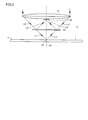
- FIG. 3 is a diagram showing the configuration and operation of the mirrow interferometer 3.
- the illumination device 1 is disposed on the side surface of the observation optical system 2 and includes a white light source 11 and a filter 12.
- the optical axis A1 of the illumination device 1 (that is, the optical axis of the white light source 11) is arranged in the horizontal direction and is orthogonal to the optical axis A2 of the observation optical system 2.
- the white light source 11 emits white light.
- the filter 12 is disposed between the white light source 11 and the observation optical system 2 and allows white light having a predetermined center wavelength ⁇ 0 and a wavelength range ⁇ among white light emitted from the white light source 11 to pass therethrough.
- the observation optical system 2 includes a condenser lens 21, a half mirror 22, and an imaging lens 23.
- the optical axis A2 of the observation optical system 2 (that is, the optical axis of the imaging lens 23) is arranged in the vertical direction.
- the condenser lens 21 is disposed between the filter 12 and the half mirror 22, and converts the white light emitted from the white light source 11 and passed through the filter 12 into parallel light.
- the half mirror 22 is disposed at the intersection of the two optical axes A1 and A2, and is disposed at an angle of 45 degrees with respect to each of the two optical axes A1 and A2.
- the Millo interferometer 3 is disposed below the half mirror 22, and the imaging lens 23 and the imaging device 4 are disposed above the half mirror 22.
- the half mirror 22 reflects the white light incident from the illumination device 1 via the condenser lens 21 downward, and allows the light from the mirrow interferometer 3 (that is, an image of interference fringes) to pass upward.
- the imaging lens 23 forms an image of the light from the Milo interferometer 3 on the optical sensor of the imaging device 4.
- the Miro interferometer 3 is provided at the lower end of the observation optical system 2 through the piezo stage 5 and includes an objective lens 31, a reflecting mirror 32, and a semi-transparent mirror 33.
- the optical axis A3 of the Millo interferometer 3 (that is, the optical axis of the objective lens 31) coincides with the optical axis A2 of the observation optical system 2.
- the piezo stage 5 moves the mirro interferometer 3 in the direction of the optical axis A3. 2 and 3, the object 7 is a substrate, the optical axis A3 is arranged perpendicular to the surface of the substrate, and the focal point P1 (that is, the focal point of the objective lens 31) of the mirro interferometer 3 is arranged on the surface of the substrate. The state is shown.
- the reflecting mirror 32 is fixed to the center of the lower surface of the objective lens 31 with its reflecting surface (reference surface) facing downward.
- the semi-transparent mirror 33 is disposed at an intermediate position between the reflecting surface of the reflecting mirror 32 and the focal point P1.
- Each of the reflecting mirror 32 and the semi-transparent mirror 33 is orthogonal to the optical axis A3.
- the white light L0 emitted from the illumination device 1 and incident on the mirro interferometer 3 via the observation optical system 2 is refracted by the objective lens 31 and travels toward the focal point P1, as shown in FIG.
- Part of the white light L0 passes through one end portion of the semi-transparent mirror 33 to become the first light beam L1
- the remaining part of the white light L0 is reflected by one end portion of the semi-transparent mirror 33 and becomes the second light beam L2.
- the white light L0 is separated into the first and second light beams L1 and L2 by the half mirror 33.
- the first light beam L1 is reflected by the surface of the object 7 to become the first reflected light L1r, and travels toward the other end of the semi-transparent mirror 33.
- the second light beam L2 is reflected by the reflecting surface of the reflecting mirror 32 to become second reflected light L2r, and travels toward the other end of the semi-transparent mirror 33.
- the first and second reflected lights L1r and L2r merge at the other end of the semi-transparent mirror 33 and interfere with each other to become interference light L3.
- the amplitude of the interference light L3 is maximized and the brightness of the interference light L3 is maximized.
- the phase difference between the two reflected lights L1r and L2r is 180 degrees, the amplitude of the interference light L3 is minimized, and the brightness of the interference light L3 is minimized.
- the mirrow interferometer 3 is designed so that the difference in optical path length between the reflected lights L1r and L2r becomes zero when the first light beam L1 is reflected at the focal point P1.
- the focal point P1 of the mirrow interferometer 3 coincides with the surface of the object 7 (that is, when the focal point is in focus)
- the phase difference and the optical path length difference between the reflected light L1r and L2r are both 0, and the interference light L3 Becomes the brightest, and the interference light L3 becomes darker as the distance between the focal point P1 and the surface of the object 7 increases.
- Interference fringes corresponding to the surface shape of the object 7 appear on the semi-transparent mirror 33. The surface shape of the object 7 can be measured based on the interference fringes.
- the control device 6 controls the imaging device 4 and the piezo stage 5 to photograph a plurality of images at a plurality of positions while moving the mirrow interferometer 3 in the direction of the optical axis A3.
- a luminance histogram of each of a plurality of images is created, a separation value R obtained by a discriminant analysis method is obtained for each luminance histogram, and a mirrow interferometer 3 is disposed at a position where the separation value R is maximum.
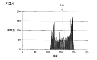
- FIG. 4 is a luminance histogram of an interference fringe image.
- the image includes a plurality of pixels arranged in a plurality of rows and a plurality of columns. Each pixel displays the luminance at any one of a plurality of levels (for example, 256 levels).
- the horizontal axis of FIG. 4 indicates the luminance at a plurality of levels, and the vertical axis indicates the number of pixels displaying each luminance.
- the luminance histogram of an image is separated into two classes CL1 and CL2 by the luminance threshold value Lth.
- Class CL1 is a group of pixels whose luminance is smaller than luminance threshold Lth.
- Class CL2 is a group of pixels whose luminance is greater than luminance threshold Lth.
- the luminance threshold Lth is set so that the intra-class variance ⁇ W 2 is minimized and the inter-class variance ⁇ B 2 is maximized, and the ratio ⁇ between the inter-class variance ⁇ B 2 and the intra-class variance ⁇ W 2 B 2 / ⁇ W 2 is the separation degree R.
- the intra-class variance ⁇ W 2 is the degree of spread of the histogram within the class
- the inter-class variance ⁇ B 2 is the degree of spread between the two classes CL1 and CL2.
- the intra-class variance ⁇ W 2 and the inter-class variance ⁇ B 2 are respectively expressed by equations (1) and (2).
- ⁇ W 2 (n 1 ⁇ ⁇ 1 2 + n 2 ⁇ ⁇ 2 2 ) / (n 1 + n 2 ) (1)
- ⁇ B 2 [n 1 ( ⁇ 1 ⁇ 0 ) 2 + n 2 ( ⁇ 2 ⁇ 0 ) 2 ] / (n 1 + n 2 ) (2)
- ⁇ 1 2 and ⁇ 2 2 are the variances of the luminance in the classes CL1 and CL2, respectively
- ⁇ 0 is the average value of the luminance of all the pixels
- ⁇ 1 and ⁇ 2 are the luminances in the classes CL1 and CL2, respectively.
- N 1 and n 2 are the numbers of pixels in the classes CL1 and CL2, respectively.
- FIG. 5 is a diagram illustrating the relationship between the position h of the piezo stage 5 and the degree of separation R.
- a plurality of images are photographed while changing the position h of the piezo stage 5 (the coordinate in the height direction of the movable part of the piezo stage 5) from 0 ⁇ m to 20 ⁇ m, and a luminance histogram of each image is generated.
- the case where the degree of separation R of the histogram is obtained is shown.
- the degree of separation R increases from 0 when h ⁇ 7.5 ⁇ m, reaches a maximum value (about 0.105) when h ⁇ 9.2 ⁇ m, then decreases, and h When it reached ⁇ 10.7 ⁇ m, it became zero.
- the focal point P1 of the mirrow interferometer 3 is placed on the surface of the object 7. I was able to match.
- the control device 6 controls the imaging device 4 and the piezo stage 5 during the autofocus operation, and takes images at a plurality of positions h while moving the mirrow interferometer 3 in the direction of the optical axis A3 at a constant speed V1.
- the image capture period of the imaging device 4 is T1 (seconds) and the center wavelength of the white light output from the illumination device 1 is ⁇ 0 ( ⁇ m)
- the Miro interferometer during the capture period T1 (seconds).
- the moving speed V1 of the Milo type interferometer 3 is set so that 3 moves by ⁇ 0 / 8 ( ⁇ m).
- the direction in which the mirrow interferometer 3 first moves is any one of the direction in which the mirrow interferometer 3 approaches the object 7 and the direction in which the mirrow interferometer 3 moves away.
- the control device 6 While the Miro interferometer 3 is moved at a constant speed V1 by the piezo stage 5, the control device 6 captures an image from the imaging device 4 at a predetermined period T1 (seconds). The control device 6 calculates the image separation degree R every time the image capture is completed, and obtains the position hf of the piezo stage 5 when the image having the maximum separation degree R is taken. Finally, the control device 6 sets the position h of the piezo stage 5 to the position hf when the image having the maximum degree of separation R is taken, and ends the autofocus operation.
- the control device 6 starts calculating the image separation degree R while capturing images from the imaging device 4 at intervals of T1 (seconds).
- the separation degree R is stored in a memory unit (not shown) in association with the position h of the piezo stage 5 at the time of capture.
- the horizontal axis shows the position h and the vertical axis shows the separation degree R.
- the piezo stage 5 is movable from the position h1 to the position h2, and the piezo stage 5 is moved in the direction from h2 to h1.
- the piezo stage 5 when the degree of separation R decreases with respect to the moving direction of the position h of the piezo stage 5, the piezo stage 5 is temporarily stopped and then shown in FIG. As shown, the piezo stage 5 is moved in the opposite direction, and an image is captured at a predetermined cycle T1 (seconds) while moving the piezo stage 5 until the position h reaches h2. From the beginning, when the degree of separation R increases with respect to the moving direction of the position h of the piezo stage 5, an image is captured at a predetermined cycle T1 (seconds) while moving the piezo stage 5 until the position h becomes h1. .
- the image separation degree R is obtained while capturing the image, and the position h of the piezo stage 5 corresponding to the image with the separation degree R having the maximum value Rmax is obtained. That is, after storing a plurality of sets (for example, eight sets) of separation degrees R and positions h, a maximum value Rmax of the plurality of separation values R is obtained.
- the absolute value ⁇ Rs
- of the difference between the maximum value Rmax and the first set of separation values Rs and the absolute value ⁇ Re
- is obtained, and when ⁇ Rs and ⁇ Re are both greater than a predetermined threshold value Rth, the position hf of the piezo stage 5 corresponding to the image having the separation degree R of the maximum value Rmax is obtained, and the piezo is located at the position hf. The stage 5 is moved. At this time, the position of the focal point P ⁇ b> 1 of the millo interferometer 3 coincides with the surface of the object 7.
- the search is continued until the piezo stage position reaches h1 or h2. If Rmax in which ⁇ Rs and ⁇ Re are both greater than the predetermined threshold value Rth cannot be detected even when h1 or h2 is reached, the piezo stage 5 is returned to the search start position, and the piezo stage position is h1 or The search is continued until h2 is reached. If Rmax in which ⁇ Rs and ⁇ Re are both greater than a predetermined threshold value Rth cannot be detected between h1 and h2, the autofocus operation is terminated as a failure.
- the search was started in the opposite direction as shown in FIG.
- the piezo stage 5 and the imaging device 4 are controlled, and images are taken at a plurality of positions h while moving the mirrow interferometer 3 in the optical axis direction.
- the separation degree R by the discriminant analysis method with respect to the luminance histogram of the pixel, and arranging the position h of the piezo stage 5 at the position hf corresponding to the image where the separation degree R of the plurality of images has the maximum value Rmax.
- the focal point P1 of the millo interferometer 3 is arranged on the surface of the object 7. Therefore, the focal point P1 of the Milo interferometer 3 can be easily adjusted to the surface of the object 7, and the working efficiency can be improved.
- the object 7 is fixed and the mirrow interferometer 3 is moved by the piezo stage 5.
- the present invention is not limited to this, and the object 7 and the mirrow interferometer 3 are relatively moved. As long as it is moved to, it may be moved by any method.
- the mirrow interferometer 3 may be fixed and the object 7 may be moved, or both the mirrow interferometer 3 and the object 7 may be moved in opposite directions.
- the Milo interferometer 3 In the first embodiment, the case where the Milo interferometer 3 is used has been described. However, the present invention is not limited to this, and other types of interferometers may be used. For example, a Michelson interferometer or a linique interferometer may be used.
- FIG. 7 is a diagram showing the configuration of the shape measuring apparatus according to the second embodiment of the present invention, and is compared with FIG. Referring to FIG. 7, this shape measuring apparatus is different from the shape measuring apparatus of FIG. 1 in that a Z stage (second positioning device) 40 is added.
- the illumination device 1, the observation optical system 2, the Millo interferometer 3, the imaging device 4, and the piezo stage 5 constitute one optical unit, and this optical unit is mounted on the Z stage 40.
- the Z stage 40 is controlled by the control device 6 and moves the optical unit in the height direction.
- the stroke of the Z stage 40 is larger than the stroke of the piezo stage 5.
- a plurality of images are photographed while moving the mirrow interferometer 3 only by the piezo stage 5 and focused based on the separation degree R of the plurality of photographed images (first autofocus operation)
- first autofocus operation a plurality of images are captured while the Miro interferometer 3 is moved by the Z stage 40, and the differential values of the plurality of images captured.
- the focal position is roughly adjusted based on D (second automatic focusing operation). This is effective when focus cannot be achieved within the stroke of the piezo stage 5.
- the control device 6 controls the imaging device 4 and the Z stage 40, and moves the mirrow interferometer 3 in the direction of the optical axis A3 at a constant speed V2 at each of a plurality of positions H. Take a picture.
- the moving speed V2 of the Z stage 40 is larger than the moving speed V1 of the piezo stage 5.
- the direction in which the mirrow interferometer 3 first moves is any one of the direction in which the mirrow interferometer 3 approaches the object 7 and the direction in which the mirrow interferometer 3 moves away.
- the control device 6 captures an image from the imaging device 4 at a predetermined cycle T2 (seconds).
- the control device 6 calculates the differential value D of the image every time the image capture is completed, and the position Hf of the Z stage 40 (movable part of the Z stage 40) when the image having the maximum differential value D is taken. For the height direction).
- the control device 6 sets the position H of the Z stage 40 to the position Hf when the image having the maximum differential value D is taken, and ends the second autofocus operation.
- the differential value D of the image is expressed by equations (3), (4), and (5).
- F indicates the captured image
- (x, y) indicates the pixel position of the image F
- dx indicates the horizontal differential value
- dy indicates the vertical differential value.
- the control device 6 starts calculating the differential value D of the image while capturing the image from the imaging device 4 at intervals of T2 (seconds), and
- the differential value D is stored in a memory unit (not shown) in association with the position H of the Z stage 40 at the time of capture.
- FIG. 8A shows a state in which the Z stage 40 is movable from the position H1 to the position H2, and the Z stage 40 is moved in the direction from H2 to H1.
- the Z stage 40 when the differential value D is decreasing with respect to the moving direction of the position H of the Z stage 40, the Z stage 40 is temporarily stopped and then shown in FIG. 8B. As shown, the Z stage 40 is moved in the opposite direction, and an image is captured at a predetermined cycle T2 (seconds) while moving the Z stage 40 until the position H reaches H2. When the differential value D increases from the beginning with respect to the movement direction of the position H of the Z stage 40, an image is captured at a predetermined cycle T2 (seconds) while moving the Z stage 40 until the position H becomes H1. .
- the image differential value D is obtained while capturing the image, and the position Hf of the Z stage 40 corresponding to the image where the differential value D is the maximum value Dmax is obtained. That is, after storing a plurality of sets (for example, 8 sets) of differential values D and positions H, a maximum value Dmax of the plurality of differential values D is obtained.
- the absolute value ⁇ Ds
- of the difference between the maximum value Dmax and the first set of differential values Ds, and the absolute value ⁇ De
- is obtained, and when both ⁇ Ds and ⁇ De are larger than a predetermined threshold value Dth, the position Hf of the Z stage 40 corresponding to the image where the differential value D becomes the maximum value Dmax is obtained. The stage 40 is moved. At this time, the position of the focal point P ⁇ b> 1 of the Milo type interferometer 3 substantially coincides with the surface of the object 7.
- the search is continued until the piezo stage position reaches H1 or H2. If Dmax in which both ⁇ Ds and ⁇ De are larger than the predetermined threshold value Dth cannot be detected even when H1 or H2 is reached, the piezo stage 5 is returned to the search start position, and the piezo stage position is H1 or The search continues until H2 is reached. If Dmax in which ⁇ Ds and ⁇ De are both greater than a predetermined threshold value Dth cannot be detected between H1 and H2, the autofocus operation is terminated as a failure.
- the Z stage 40 is fixed at the position Hf corresponding to the image where the differential value D becomes the maximum value Dmax, and the focus of the Milo type interferometer 3 by the method described in the first embodiment (first autofocus operation). P1 is precisely matched with the surface of the object 7.
- the search was started in the opposite direction as shown in FIG.
- the Z stage 40 and the imaging device 4 are controlled, and the Milo interferometer 3 is operated.
- Each image is photographed at a plurality of positions H while moving in the optical axis direction, a differential value D of each image is obtained, and Z is located at a position Hf corresponding to an image having the maximum differential value D among the plurality of images.
- the focal point P1 of the Milo type interferometer 3 is approximately matched with the surface of the object 7. Therefore, even when the focal point P1 cannot be adjusted only by the piezo stage 5, the focal point P1 of the mirrow interferometer 3 can be easily adjusted to the surface of the object 7, and the working efficiency can be improved.
- the object 7 is fixed and the Miro interferometer 3 is moved by the Z stage 40.
- the present invention is not limited to this, and the object 7 and the Miro interferometer 3 are relatively moved. As long as it is moved to, it may be moved by any method.
- the mirrow interferometer 3 may be fixed and the object 7 may be moved, or both the mirrow interferometer 3 and the object 7 may be moved in opposite directions.
- the Milo interferometer 3 In the second embodiment, the case where the Milo interferometer 3 is used has been described. However, the present invention is not limited to this, and other types of interferometers may be used. For example, a Michelson interferometer or a linique interferometer may be used.
- FIG. 9 is a perspective view showing an overall configuration of coating apparatus 100 provided with the shape measuring apparatus according to the present embodiment.
- the coating apparatus 100 is configured to be able to apply a transparent ink (liquid material) over a plurality of layers on the main surface of the substrate 9.
- a coating apparatus 100 includes a coating head unit that includes an observation optical system 2, a CCD camera 4, a cutting laser device 8, an ink coating mechanism 50, and an ink curing light source 20, and the coating head.
- Z stage 40 for moving the portion in the vertical direction (Z-axis direction) with respect to substrate 9 to be coated
- X stage 42 for mounting Z stage 40 and moving in the X-axis direction
- Y for mounting substrate 9
- An Y stage 44 that moves in the axial direction
- a control computer 70 that controls the operation of the entire apparatus
- a monitor 74 that displays an image taken by the CCD camera 4, and a command from the operator to the control computer 70
- an operation panel 72 for inputting.
- the observation optical system 2 includes a light source for illumination (the illumination device 1 in FIG. 1), and observes the surface state of the substrate 9 and the state of ink applied by the ink application mechanism 50. An image observed by the observation optical system 2 is converted into an electrical signal by the CCD camera 4 and displayed on the monitor 74.
- the cutting laser device 8 removes unnecessary portions on the substrate 9 by irradiating them with laser light via the observation optical system 2.
- the ink application mechanism 50 applies ink onto the main surface of the substrate 9.
- the ink curing light source 20 includes, for example, a CO 2 laser, and cures the ink applied by the ink application mechanism 50 by irradiating the laser beam.
- This apparatus configuration is an example.
- the Z stage 40 on which the observation optical system 2 and the like are mounted is mounted on the X stage, the X stage is mounted on the Y stage, and the Z stage 40 can be moved in the XY directions.
- a configuration called a gantry system may be used, and any configuration may be used as long as the Z stage 40 on which the observation optical system 2 and the like are mounted can be moved relative to the target substrate 9 in the XY directions.
- FIG. 10 is a perspective view showing the main parts of the observation optical system 2 and the ink application mechanism 50.
- this coating apparatus 100 includes a movable plate 15, a plurality (for example, five) objective lenses 19 having different magnifications, and a plurality (for example, five) for applying inks made of different materials. And a coating unit 17.
- the movable plate 15 is provided between the lower end of the observation barrel 2a of the observation optical system 2 and the substrate 9 so as to be movable in the X-axis direction and the Y-axis direction. Further, for example, five through holes 15 a are formed in the movable plate 15.
- the objective lens 19 is fixed to the lower surface of the movable plate 15 so as to correspond to the through holes 15a at predetermined intervals in the Y-axis direction.
- Each of the five coating units 17 is disposed adjacent to the five objective lenses 19. By moving the movable plate 15, a desired coating unit 17 can be disposed above the target substrate 9.
- the application unit 17 includes an application needle 170 and an ink tank 172.
- the application needle 170 of the desired application unit 17 is positioned above the target substrate 9. At this time, the tip of the application needle 170 is immersed in the ink in the ink tank 172.
- the application needle 170 is lowered to project the tip of the application needle 170 from the hole at the bottom of the ink tank 172. At this time, ink adheres to the tip of the application needle 170.
- the application needle 170 and the ink tank 172 are lowered to bring the tip of the application needle 170 into contact with the substrate 9, and ink is applied to the substrate 9. Thereafter, the state returns to the state of FIG.
- the ink application mechanism using a plurality of application needles is not described in detail since various other techniques are known. For example, it is shown in Patent Document 1.
- the application apparatus 100 can apply a desired ink of a plurality of inks by using a mechanism as shown in FIG. 10 as the ink application mechanism 50, for example, and can also apply a desired application of a plurality of application needles.
- the ink can be applied using a diameter application needle.
- the head unit 10 (FIG. 1) of the shape measuring apparatus according to the present embodiment is provided in the observation optical system 2 of the coating apparatus 100, for example.
- the control computer 70 controls the ink application mechanism 50 to perform the ink application operation, and then moves the Z stage 40 to position the head unit 10 at a predetermined position above the surface of the ink application part. Further, the control computer 70 takes an image of the interference light by the CCD camera 4 while moving the Z stage 40 relative to the substrate 9.
- the control computer 70 detects the Z stage position where the interference light intensity reaches a peak for each pixel, and calculates the film thickness of the ink application part or the height of the uneven part using the detected Z stage position.
- the coating apparatus 100 moves the mirro interferometer 3 relative to the object using the Z stage 40, automatically detects the focus by the method shown in the first embodiment, and determines the detected focus position. Ink application operation is performed as a reference.
- Interference fringes generated by the Milo interferometer 3 appear when the surface to be detected is focused. Therefore, it is effective for focusing when a smooth surface having no irregularities such as a glass surface, a metal thin film, or a chromium film is used as a reference surface in the height direction of the coating operation.
- a smooth surface such as a metal thin film may be selected as a reference surface in the height direction of the coating operation.
- the focal position can be detected with high accuracy.
- the offset amount between the application unit 92 and the tip of the application needle 170 is obtained in advance and stored in the control computer 70 of the application apparatus 100.
- the offset amount is obtained as follows.
- the control computer 70 focuses on the area AR set on the surface of the metal thin film 91 that is the reference plane by the method shown in the first embodiment. Specifically, a luminance histogram is obtained for the pixels in the area AR, the degree of separation R is calculated based on the luminance histogram, and the autofocus operation is executed.
- control computer 70 moves the movable plate 15 of the ink application mechanism 50 of the application device 100 in the X-axis direction or the Y-axis direction in FIG. 10 and moves the application needle 170 above the application unit 92. Thereafter, as shown in FIG. 14, the control computer 70 lowers the Z stage 40 by ⁇ z, then controls the ink application mechanism 50 to execute the application operation described in FIG. Return to the original position.
- the monitor 74 of the coating apparatus 100 is checked, and when ink is not applied to the coating unit 92, ⁇ z is changed and the above procedure is executed again. This operation is repeated until ink is applied to the application section 92, and ⁇ z when the ink is applied for the first time is stored in the control computer 70.
- the method shown in the first embodiment is used to focus on the surface of the metal thin film 91 which is the reference surface, and then the movable plate 15 of the ink coating mechanism 50 of the coating apparatus 100 is moved to the X in FIG. Moving in the axial direction or the Y-axis direction, the application needle 170 is moved above the application unit 92. Thereafter, after the Z stage 40 is lowered by ⁇ z, the ink application mechanism 50 is controlled to perform the application operation, and the movable plate 15 is returned to the original position.
- the metal thin film 91 and the coating part 92 are described as having the same height.
- the Z stage 40 is moved by the subtraction ( ⁇ z ⁇ d).
- the Z stage 40 is moved by ( ⁇ z + ⁇ d) where the step ⁇ d is added to ⁇ z.
- the direction in which the Z stage 40 descends is positive.
- the film thickness of the applied ink is inspected.
- the surface shape can be measured using a method described in JP-A-2015-007564. As shown in FIG. 17, a step ⁇ t between the metal thin film 91 and the apex portion of the applied ink 94 is obtained.
- step ⁇ t is smaller than the lower limit value TL stored in the control computer 70 of the coating apparatus 100 in advance, ink is applied again. At this time, if the thickness of the applied ink is ⁇ t, the ink is applied with the offset amount of the Z stage 40 as ( ⁇ z ⁇ t). This operation is repeated until the ink film thickness ⁇ t exceeds the lower limit TL. However, the number of times of application i is counted, and when i exceeds the maximum number N specified in advance, the application operation is interrupted.
- the operator checks the state of the coating unit 92 on the monitor 74 and determines whether or not the coating has been performed correctly.
- FIG. 18 is a flowchart for explaining a film thickness inspection process executed by the control computer 70.
- control computer 70 is predetermined in step (hereinafter, step is abbreviated as S) S100 as metal thin film 91 in FIG.
- the focus is adjusted with respect to the reference plane (FIG. 13).
- the control computer 70 moves from the reference surface to the tip of the application needle 170.
- the height ⁇ z is calculated.
- control computer 70 moves the X stage 42 and the Y stage 44 so that the application needle 170 is positioned above the application unit 92.
- control computer 70 determines whether or not the counter i is equal to or less than a predetermined maximum number N.
- control computer 70 raises the Z stage 40 by ⁇ z and returns it to the initial position, and further positions the objective lens 19 above the application portion 92. Then, in S140, the control computer 70 takes an image of interference light with the CCD camera 4 while moving the Z stage 40 relative to the substrate 9 in the height direction, and the interference light intensity reaches a peak. From the position of the Z stage 40, the height (film thickness) ⁇ t from the reference surface of the apex portion of the applied ink is measured (FIG. 17).
- step S150 the control computer 70 determines whether the measured film thickness ⁇ t of the ink portion is equal to or greater than a predetermined lower limit TL ( ⁇ t ⁇ TL).
- the control computer 70 increments the counter i in S160, returns the process to S120, and applies again. Perform the action. At this time, the descending amount of the application needle 170 is corrected to ( ⁇ z ⁇ t).
- the control computer 70 interrupts the coating operation. .
- control computer 70 ends the coating operation assuming that the coating is completed.
- the height of the applied ink can be accurately and efficiently measured by controlling the coating apparatus 100 according to the above process using the shape measuring apparatus according to the present embodiment. So work efficiency can be improved.
- the positional relationship between the application needle and the application part is stabilized, so that the amount of ink adhering to the application part can be stabilized. .
Landscapes
- Physics & Mathematics (AREA)
- General Physics & Mathematics (AREA)
- Length Measuring Devices By Optical Means (AREA)
Abstract
形状測定装置の制御装置(6)は、ピエゾステージ(5)および撮像装置(4)を制御し、干渉計(3)を光軸方向に移動させながら複数の位置(h)でそれぞれの画像を撮影し、各画像の画素の輝度ヒストグラムについて判別分析法による分離度(R)を求め、複数の画像のうちの分離度(R)が最大値(Rmax)になる画像に対応する位置(hf)にピエゾステージ(5)を配置することにより、干渉計(3)の焦点(P1)を対象物(7)の表面に配置する。したがって、干渉計(3)の焦点(P1)を対象物(7)の表面に容易に合わせることができる。
Description
この発明は形状測定装置およびそれを搭載した塗布装置に関し、特に、干渉計を用いて対象物の表面形状を測定する形状測定装置に関する。より特定的には、この発明は、金属、樹脂、それらの加工品などの表面形状を測定したり、半導体装置、電子回路、フラットパネルディスプレイなどの基板の表面形状を測定する形状測定装置に関する。
特開2000-56210号公報(特許文献1)には、ZテーブルによってCCDカメラを対象物に対して移動させながら複数の位置でそれぞれの画像を撮影し、各画像に含まれる複数の画素の輝度の微分値(以下、画像の微分値と略記する場合がある)を算出し、微分値が最大になる画像に対応する位置にCCDカメラを配置することにより、CCDカメラの焦点を対象物に合わせるオートフォーカス装置が開示されている。
画像の微分値は、たとえば、対象物と背景との境界のように明暗パターンが急に変化する箇所で大きな値になる。焦点が合った状態で撮影された画像では、焦点が合っていない状態で撮影された画像に比べ、対象物と背景との境界が明瞭になり、画像の微分値が大きくなる。したがって、画像の微分値が最大になる位置にCCDカメラを配置することにより、CCDカメラの焦点を対象物に合わせることができる。
ところで、干渉計を用いて対象物の表面形状を測定する形状測定装置では、通常、対象物の基準面に干渉計の焦点を合わせてから測定を開始する。対象物の基準面としては、対象物の上端面のような平面部、あるいは球面の頂点部が選ばれることが多い。このような基準面では、形状および明暗パターンの変化が緩やかであり、干渉縞の明暗の変化も緩やかとなり、干渉縞の画像の微分値は小さい。したがって、特許文献1のように、干渉縞の画像の微分値のみを使用して干渉計の焦点を基準面に合わせることは難しい。また、従来の技術(特許文献1)では、焦点を合わせるためには目標となる模様が必要であり、目標がないと焦点合わせの作業に不具合を生じることがあった。
それゆえに、この発明の主たる目的は、干渉計の焦点を対象物の表面に容易に合わせることが可能な形状測定装置を提供することである。
この発明に係る形状測定装置は、対象物の表面形状を測定する形状測定装置であって、照明装置から出射される白色光を第1および第2の光束に分離し、第1の光束を対象物の表面に照射するとともに第2の光束を参照面に照射し、対象物の表面からの反射光と参照面からの反射光とを合成し、対象物の表面形状に対応する干渉縞を生成する干渉計と、干渉縞を観察するための観察光学系と、観察光学系を介して干渉縞の画像を撮影する撮像装置と、対象物および干渉計を光軸方向に相対移動させる第1の位置決め装置と、撮像装置および第1の位置決め装置を制御し、干渉計の焦点を対象物の表面に合わせる第1の自動焦点動作を実行する制御装置とを備えたものである。制御装置は、第1の自動焦点動作では、対象物および干渉計を光軸方向に相対移動させながら複数の相対位置でそれぞれの画像を撮影し、各画像毎に当該画像に含まれる複数の画素の輝度分布図について判別分析法による分離度を求め、複数の画像のうちの分離度が最大になる画像に対応する相対位置に対象物および干渉計を配置する。
この発明に係る形状測定装置では、各画像毎に当該画像に含まれる複数の画素の輝度分布図について判別分析法による分離度を求め、複数の画像のうちの分離度が最大になる画像に対応する相対位置に対象物および干渉計を配置することにより、干渉計の焦点を対象物の表面に合わせる。したがって、干渉計の焦点を対象物の表面に容易に合わせることができる。また、干渉計の焦点を対象物の表面に容易かつ確実に合わせることができるので、焦点合わせ後に行なう作業の不具合が生じることがなく、作業効率の向上を図ることができる。さらに、本発明の処理を含めた全作業時間を短縮することができ、製品の製造コストの低減化を図ることができる。
[実施の形態1]
図1は、この発明の実施の形態1による形状測定装置の構成を示すブロック図である。図1において、この形状測定装置は、照明装置1、観察光学系2、ミロー型干渉計3、撮像装置4、およびピエゾステージ(第1の位置決め装置)5を含んで構成されるヘッド部10と、制御装置6とを備える。照明装置1は、白色光を出力する。観察光学系2は、照明装置1から出力された白色光を反射してミロー型干渉計3に与えるとともに、ミロー型干渉計3で生成される干渉縞を観察するために用いられる。
図1は、この発明の実施の形態1による形状測定装置の構成を示すブロック図である。図1において、この形状測定装置は、照明装置1、観察光学系2、ミロー型干渉計3、撮像装置4、およびピエゾステージ(第1の位置決め装置)5を含んで構成されるヘッド部10と、制御装置6とを備える。照明装置1は、白色光を出力する。観察光学系2は、照明装置1から出力された白色光を反射してミロー型干渉計3に与えるとともに、ミロー型干渉計3で生成される干渉縞を観察するために用いられる。
ミロー型干渉計3は、照明装置1から観察光学系2を介して入射された白色光を第1および第2の光束に分離し、第1の光束を対象物7の表面に照射するとともに第2の光束を参照面に照射し、対象物7の表面からの反射光と参照面からの反射光とを干渉させて干渉縞を生成する。撮像装置4は、制御装置6によって制御され、観察光学系2を介して、ミロー型干渉計3で生成された干渉縞の画像を撮影する。撮像装置4によって撮影された各画像は、制御装置6に格納される。ピエゾステージ5は、制御装置6によって制御され、対象物7に対してミロー型干渉計3を光軸方向(垂直方向)に移動させる。
制御装置6は、形状測定装置全体を制御する。特に、制御装置6は、撮像装置4およびピエゾステージ5を制御し、対象物7に対してミロー型干渉計3を光軸方向に移動させながら、複数の位置でそれぞれの画像を撮影し、複数の画像に基づいてミロー型干渉計3の焦点を対象物7の表面に合わせる自動焦点動作(第1の自動焦点動作)を実行する。自動焦点動作については、後で詳細に説明する。
図2は図1に示した形状測定装置の構成をより詳細に示す図であり、図3はミロー型干渉計3の構成および動作を示す図である。図2および図3において、照明装置1は、観察光学系2の側面に配置され、白色光源11およびフィルタ12を含む。照明装置1の光軸A1(すなわち白色光源11の光軸)は、水平方向に配置され、観察光学系2の光軸A2と直交している。白色光源11は、白色光を出射する。フィルタ12は、白色光源11と観察光学系2の間に配置され、白色光源11から出射された白色光のうち所定の中心波長λ0および波長範囲Δλを有する白色光を通過させる。
観察光学系2は、集光レンズ21、ハーフミラー22、および結像レンズ23を含む。観察光学系2の光軸A2(すなわち結像レンズ23の光軸)は、垂直方向に配置される。集光レンズ21は、フィルタ12とハーフミラー22の間に配置され、白色光源11から出射されてフィルタ12を通過した白色光を平行光に変換する。
ハーフミラー22は、2本の光軸A1,A2の交差部に配置され、2本の光軸A1,A2の各々に対して45度の角度で配置される。ハーフミラー22の下方にミロー型干渉計3が配置され、ハーフミラー22の上方に結像レンズ23および撮像装置4が配置される。ハーフミラー22は、照明装置1から集光レンズ21を介して入射された白色光を下方に反射させるとともに、ミロー型干渉計3からの光(すなわち干渉縞の像)を上方に通過させる。結像レンズ23は、ミロー型干渉計3からの光を撮像装置4の光センサに結像させる。
ミロー型干渉計3は、ピエゾステージ5を介して観察光学系2の下端に設けられ、対物レンズ31、反射鏡32、および半透鏡33を含む。ミロー型干渉計3の光軸A3(すなわち対物レンズ31の光軸)は、観察光学系2の光軸A2と一致している。ピエゾステージ5は、ミロー型干渉計3を光軸A3の方向に移動させる。図2および図3では、対象物7は基板であり、光軸A3は基板の表面に垂直に配置され、ミロー型干渉計3の焦点P1(すなわち対物レンズ31の焦点)は基板の表面に配置されている状態が示されている。
反射鏡32は、その反射面(参照面)を下向きにして、対物レンズ31の下面の中央部に固定されている。半透鏡33は、反射鏡32の反射面と焦点P1との中間位置に配置されている。反射鏡32および半透鏡33の各々は、光軸A3と直交している。
照明装置1から出射され、観察光学系2を介してミロー型干渉計3に入射された白色光L0は、図3に示すように、対物レンズ31によって屈折されて焦点P1に向かう。白色光L0の一部は半透鏡33の一方端部を通過して第1の光束L1となり、白色光L0の残りの部分は半透鏡33の一方端部で反射されて第2の光束L2となる。すなわち、白色光L0は、半透鏡33によって第1および第2の光束L1,L2に分離される。
第1の光束L1は、対象物7の表面で反射されて第1の反射光L1rとなり、半透鏡33の他方端部に向かう。第2の光束L2は、反射鏡32の反射面で反射されて第2の反射光L2rとなり、半透鏡33の他方端部に向かう。第1および第2の反射光L1r,L2rは、半透鏡33の他方端部で合流し、互いに干渉して干渉光L3となる。
2つの反射光L1r,L2rの位相差が0度である場合、干渉光L3の振幅は最大となり、干渉光L3の明るさは最大になる。2つの反射光L1r,L2rの位相差が180度である場合、干渉光L3の振幅は最小となり、干渉光L3の明るさは最小になる。第1の光束L1が焦点P1で反射したときに反射光L1r,L2rの光路長差が0になるようにミロー型干渉計3が設計されている。
したがって、ミロー型干渉計3の焦点P1が対象物7の表面に一致したとき(すなわち焦点が合ったとき)、反射光L1r,L2rの位相差および光路長差がともに0になって干渉光L3は最も明るくなり、焦点P1と対象物7の表面との距離が大きくなるに従って干渉光L3は暗くなる。半透鏡33には、対象物7の表面形状に対応する干渉縞が現れる。この干渉縞に基づいて対象物7の表面形状を測定することができる。
鮮明な干渉縞を得るためには、ミロー型干渉計3の焦点P1を対象物7の表面に一致させる必要がある。以下、ミロー型干渉計3の焦点P1を対象物7の表面に一致させる自動焦点動作について説明する。
制御装置6は、自動焦点動作時には、撮像装置4およびピエゾステージ5を制御し、ミロー型干渉計3を光軸A3の方向に移動させながら、複数の位置で複数の画像を撮影し、撮影した複数の画像の各々の輝度ヒストグラムを作成し、各輝度ヒストグラムについて判別分析法による分離値Rを求め、分離値Rが最大となる位置にミロー型干渉計3を配置する。
図4は、ある干渉縞の画像の輝度ヒストグラムである。画像は、複数行複数列に配置された複数の画素を含む。各画素は、複数段階(たとえば256段階)の輝度のうちのいずれかの段階の輝度を表示する。図4の横軸は複数段階の輝度を示し、その縦軸は各輝度を表示する画素の数を示している。ミロー型干渉計3の焦点P1を対象物7の表面に近付けていくと、図4に示すように、輝度ヒストグラムは双峰性を示すようになる。
判別分析法では、画像の輝度ヒストグラムが輝度しきい値Lthで2つのクラスCL1,CL2に分離される。クラスCL1は、輝度が輝度しきい値Lthよりも小さな画素の集団である。クラスCL2は、輝度が輝度しきい値Lthよりも大きな画素の集団である。輝度しきい値Lthは、クラス内分散σW
2が最小となり、かつクラス間分散σB
2が最大となるように設定され、クラス間分散σB
2とクラス内分散σW
2との比σB
2/σW
2が分離度Rとされる。
クラス内分散σW
2はクラス内でのヒストグラムの広がり具合であり、クラス間分散σB
2は2つのクラスCL1,CL2の間の広がり具合である。クラス内分散σW
2およびクラス間分散σB
2はそれぞれ数式(1)(2)で表される。
σW
2=(n1×σ1
2+n2×σ2
2)/(n1+n2) …(1)
σB 2=[n1(μ1-μ0)2+n2(μ2-μ0)2]/(n1+n2) …(2)
ただし、σ1 2,σ2 2はそれぞれクラスCL1,CL2内の輝度の分散であり、μ0は全画素の輝度の平均値であり、μ1,μ2はそれぞれクラスCL1,CL2内の輝度の平均値であり、n1,n2はそれぞれクラスCL1,CL2内の画素数である。
σB 2=[n1(μ1-μ0)2+n2(μ2-μ0)2]/(n1+n2) …(2)
ただし、σ1 2,σ2 2はそれぞれクラスCL1,CL2内の輝度の分散であり、μ0は全画素の輝度の平均値であり、μ1,μ2はそれぞれクラスCL1,CL2内の輝度の平均値であり、n1,n2はそれぞれクラスCL1,CL2内の画素数である。
図5は、ピエゾステージ5の位置hと分離度Rとの関係を例示する図である。図5では、ピエゾステージ5の位置h(ピエゾステージ5の可動部の高さ方向の座標)を0μmから20μmまで変化させながら複数の画像を撮影し、各画像の輝度ヒストグラムを生成し、各輝度ヒストグラムの分離度Rを求めた場合が示されている。図5において、分離度Rは、h≒7.5μmになった時点で0から上昇し、h≒9.2μmになった時点で最大値(約0.105)となり、その後に下降し、h≒10.7μmになった時点で0となった。分離度Rが最大値(約0.105)となったときの位置(h≒9.2μm)にピエゾステージ5を配置することにより、ミロー型干渉計3の焦点P1を対象物7の表面に一致させることができた。
次に、この形状測定装置における自動焦点動作について具体的に説明する。制御装置6は、自動焦点動作時には、撮像装置4およびピエゾステージ5を制御し、ミロー型干渉計3を光軸A3の方向に一定速度V1で移動させながら複数の位置hでそれぞれの画像を撮影する。撮像装置4の画像の取込周期をT1(秒)とし、照明装置1から出力される白色光の中心波長をλ0(μm)とすると、取込周期T1(秒)の間にミロー型干渉計3がλ0/8(μm)だけ移動するように、ミロー型干渉計3の移動速度V1が設定される。ミロー型干渉計3が最初に移動する方向は、ミロー型干渉計3が対象物7に近づく方向と遠ざかる方向とのうちのいずれか一方の方向とする。
ミロー型干渉計3がピエゾステージ5によって一定速度V1で移動されている間、制御装置6は撮像装置4から所定周期T1(秒)で画像を取り込む。制御装置6は、画像の取込が完了する度に画像の分離度Rを算出し、分離度Rが最大となる画像が撮影されたときのピエゾステージ5の位置hfを求める。最終的に、制御装置6は、分離度Rが最大となる画像が撮影されたときの位置hfにピエゾステージ5の位置hを設定して自動焦点動作を終了する。
詳しく説明すると、制御装置6は、ピエゾステージ5の駆動速度が一定速度V1に到達すると、撮像装置4から画像をT1(秒)間隔で取り込みながら画像の分離度Rの計算を開始し、画像を取り込んだときのピエゾステージ5の位置hと関連付けて分離度Rをメモリ部(図示せず)に記憶する。
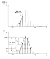
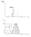
複数組(たとえば3組)の分離度Rおよび位置hを記憶した後、図6(a)(b)に示すように、横軸が位置hを示し、縦軸が分離度Rを示す図を書き、複数の点を結ぶ近似直線を書く。図6(a)では、ピエゾステージ5は位置h1から位置h2まで移動可能であり、h2からh1に向かう方向にピエゾステージ5が移動されている状態が示されている。
たとえば図6(a)に示すように、ピエゾステージ5の位置hの移動方向に対して分離度Rが減少している場合は、ピエゾステージ5を一旦停止させた後、図6(b)に示すように、ピエゾステージ5を反対方向に移動させ、位置hがh2になるまでピエゾステージ5を移動させながら所定周期T1(秒)で画像を取り込む。最初から、ピエゾステージ5の位置hの移動方向に対して分離度Rが増加している場合は、位置hがh1になるまでピエゾステージ5を移動させながら所定周期T1(秒)で画像を取り込む。
画像を取り込みながら画像の分離度Rを求め、分離度Rが最大値Rmaxとなる画像に対応するピエゾステージ5の位置hを求める。すなわち、複数組(たとえば8組)の分離度Rおよび位置hを記憶した後、複数個の分離値Rのうちの最大値Rmaxを求める。次に、最大値Rmaxと最初の組の分離値Rsとの差の絶対値ΔRs=|Rmax-Rs|と、最大値Rmaxと最後の組の分離値Reとの差の絶対値ΔRe=|Rmax-Re|とを求め、ΔRsとΔReがともに所定のしきい値Rthよりも大きいとき、分離度Rが最大値Rmaxとなる画像に対応するピエゾステージ5の位置hfを求め、その位置hfにピエゾステージ5を移動させる。このとき、ミロー型干渉計3の焦点P1の位置が対象物7の表面に一致している。
ΔRs,ΔReのうちの少なくとも一方がしきい値Rthよりも小さい場合は、ピエゾステージ位置がh1またはh2に達するまで探索を続ける。h1またはh2に達してもΔRsとΔReがともに所定のしきい値Rthよりも大きくなるRmaxを検出できなかったときは、探索開始位置にピエゾステージ5を戻し、反対方向にピエゾステージ位置がh1またはh2に達するまで探索を続ける。h1~h2の間で、ΔRsとΔReがともに所定のしきい値Rthよりも大きくなるRmaxを検出できなかったときは自動焦点動作を失敗として終了する。
具体的に説明すると、図6(a)では、N=1の位置から画像の取り込みを開始し、N=3の位置で画像を取り込んだ後、3点を結ぶ近似直線を求め、移動方向に対して近似直線の傾きが負であると判定し、図6(b)に示すように、反対方向に探索を開始した。反対方向の探索では、M=1の位置から画像の取り込みを開始し、M=8の位置から画像を取り込んだ後、ピーク判定を開始し、M=5の位置の分離度Rが最大値Rmaxであると判定し、ΔRs,ΔReがともにしきい値Rthよりも大きいと判定し、M=5に対応する位置hfにピエゾステージ5を配置し、ミロー型干渉計3の焦点P1を対象物7の表面に合わせた。
以上のように、この実施の形態1では、ピエゾステージ5および撮像装置4を制御し、ミロー型干渉計3を光軸方向に移動させながら複数の位置hでそれぞれの画像を撮影し、各画像の画素の輝度ヒストグラムについて判別分析法による分離度Rを求め、複数の画像のうちの分離度Rが最大値Rmaxになる画像に対応する位置hfにピエゾステージ5の位置hを配置することにより、ミロー型干渉計3の焦点P1を対象物7の表面に配置する。したがって、ミロー型干渉計3の焦点P1を対象物7の表面に容易に合わせることができ、作業効率の向上を図ることができる。
なお、この実施の形態1では、対象物7を固定し、ピエゾステージ5によってミロー型干渉計3を移動させたが、これに限るものではなく、対象物7とミロー型干渉計3を相対的に移動させるのであれば、どのような方法で移動させても構わない。たとえば、ミロー型干渉計3を固定して対象物7を移動させてもよいし、ミロー型干渉計3と対象物7の両方を逆方向に移動させても構わない。
また、この実施の形態1では、ミロー型干渉計3を用いた場合について説明したが、これに限るものではなく、他の型式の干渉計を用いてもよい。たとえば、マイケルソン型干渉計あるいはリニーク型干渉計を用いてもよい。
[実施の形態2]
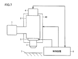
図7は、この発明の実施の形態2による形状測定装置の構成を示す図であって、図1と対比される図である。図7を参照して、この形状測定装置が図1の形状測定装置と異なる点は、Zステージ(第2の位置決め装置)40が追加されている点である。照明装置1、観察光学系2、ミロー型干渉計3、撮像装置4、およびピエゾステージ5は1つの光学ユニットを構成し、この光学ユニットはZステージ40に搭載されている。Zステージ40は、制御装置6によって制御され、光学ユニットを高さ方向に移動させる。
図7は、この発明の実施の形態2による形状測定装置の構成を示す図であって、図1と対比される図である。図7を参照して、この形状測定装置が図1の形状測定装置と異なる点は、Zステージ(第2の位置決め装置)40が追加されている点である。照明装置1、観察光学系2、ミロー型干渉計3、撮像装置4、およびピエゾステージ5は1つの光学ユニットを構成し、この光学ユニットはZステージ40に搭載されている。Zステージ40は、制御装置6によって制御され、光学ユニットを高さ方向に移動させる。
Zステージ40のストロークは、ピエゾステージ5のストロークよりも大きい。実施の形態1では、ピエゾステージ5のみによってミロー型干渉計3を移動させながら複数の画像を撮影し、撮影した複数の画像の分離度Rに基づいて焦点を合わせた(第1の自動焦点動作)が、この実施の形態2では、第1の自動焦点動作を実行する前に、Zステージ40によってミロー型干渉計3を移動させながら複数の画像を撮影し、撮影した複数の画像の微分値Dに基づいて焦点の位置を粗調整する(第2の自動焦点動作)。ピエゾステージ5のストローク内で焦点を合わすことができない場合に有効である。
次に、この形状測定装置における第2の自動焦点動作について具体的に説明する。制御装置6は、第2の自動焦点動作時には、撮像装置4およびZステージ40を制御し、ミロー型干渉計3を光軸A3の方向に一定速度V2で移動させながら複数の位置Hでそれぞれの画像を撮影する。Zステージ40の移動速度V2は、ピエゾステージ5の移動速度V1よりも大きい。ミロー型干渉計3が最初に移動する方向は、ミロー型干渉計3が対象物7に近づく方向と遠ざかる方向とのうちのいずれか一方の方向とする。
ミロー型干渉計3がZステージ40によって一定速度V2で移動されている間、制御装置6は撮像装置4から所定周期T2(秒)で画像を取り込む。制御装置6は、画像の取込が完了する度に画像の微分値Dを算出し、微分値Dが最大となる画像が撮影されたときのZステージ40の位置Hf(Zステージ40の可動部の高さ方向の座標)を求める。最終的に、制御装置6は、微分値Dが最大となる画像が撮影されたときの位置HfにZステージ40の位置Hを設定して第2の自動焦点動作を終了する。画像の微分値Dは、数式(3)(4)(5)で表される。
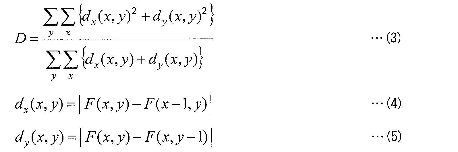
ただし、Fは取り込んだ画像を示し、(x,y)は画像Fの画素の位置を示し、dxは水平方向の微分値を示し、dyは垂直方向の微分値を示す。
詳しく説明すると、制御装置6は、Zステージ40の駆動速度が一定速度V2に到達すると、撮像装置4から画像をT2(秒)間隔で取り込みながら画像の微分値Dの計算を開始し、画像を取り込んだときのZステージ40の位置Hと関連付けて微分値Dをメモリ部(図示せず)に記憶する。
複数組(たとえば3組)の微分値Dおよび位置Hを記憶した後、図8(a)(b)に示すように、横軸が位置Hを示し、縦軸が微分値Dを示す図を書き、複数の点を結ぶ近似直線を書く。図8(a)では、Zステージ40は位置H1から位置H2まで移動可能であり、H2からH1に向かう方向にZステージ40が移動されている状態が示されている。
たとえば図8(a)に示すように、Zステージ40の位置Hの移動方向に対して微分値Dが減少している場合は、Zステージ40を一旦停止させた後、図8(b)に示すように、Zステージ40を反対方向に移動させ、位置HがH2になるまでZステージ40を移動させながら所定周期T2(秒)で画像を取り込む。最初から、Zステージ40の位置Hの移動方向に対して微分値Dが増加している場合は、位置HがH1になるまでZステージ40を移動させながら所定周期T2(秒)で画像を取り込む。
画像を取り込みながら画像の微分値Dを求め、微分値Dが最大値Dmaxとなる画像に対応するZステージ40の位置Hfを求める。すなわち、複数組(たとえば8組)の微分値Dおよび位置Hを記憶した後、複数個の微分値Dのうちの最大値Dmaxを求める。次に、最大値Dmaxと最初の組の微分値Dsとの差の絶対値ΔDs=|Dmax-Ds|と、最大値Dmaxと最後の組の微分値Deとの差の絶対値ΔDe=|Dmax-De|とを求め、ΔDsとΔDeがともに所定のしきい値Dthよりも大きいとき、微分値Dが最大値Dmaxとなる画像に対応するZステージ40の位置Hfを求め、その位置HfにZステージ40を移動させる。このとき、ミロー型干渉計3の焦点P1の位置が対象物7の表面に大体一致している。
ΔDs,ΔDeのうちの少なくとも一方がしきい値Dthよりも小さい場合は、ピエゾステージ位置がH1またはH2に達するまで探索を続ける。H1またはH2に達してもΔDsとΔDeがともに所定のしきい値Dthよりも大きくなるDmaxを検出できなかったときは、探索開始位置にピエゾステージ5を戻し、反対方向にピエゾステージ位置がH1またはH2に達するまで探索を続ける。H1~H2の間で、ΔDsとΔDeがともに所定のしきい値Dthよりも大きくなるDmaxを検出できなかったときは自動焦点動作を失敗として終了する。
この後、微分値Dが最大値Dmaxとなる画像に対応する位置HfにZステージ40を固定し、実施の形態1で説明した方法(第1の自動焦点動作)でミロー型干渉計3の焦点P1を対象物7の表面に精密に一致させる。
具体的に説明すると、図8(a)では、N=1の位置から画像の取り込みを開始し、N=3の位置で画像を取り込んだ後、3点を結ぶ近似直線を求め、移動方向に対して近似直線の傾きが負であると判定し、図8(b)に示すように、反対方向に探索を開始した。反対方向の探索では、M=1の位置から画像の取り込みを開始し、M=8の位置から画像を取り込んだ後、ピーク判定を開始し、M=5の位置の微分値Dが最大値Dmaxであると判定し、ΔDs,ΔDeがともにしきい値Dthよりも大きいと判定し、M=5に対応する位置HfにZステージ40を配置し、ミロー型干渉計3の焦点P1を対象物7の表面に大体一致させた。
以上のように、この実施の形態2では、実施の形態1の方法(第1の自動焦点動作)によって焦点を合わせる前に、Zステージ40および撮像装置4を制御し、ミロー型干渉計3を光軸方向に移動させながら複数の位置Hでそれぞれの画像を撮影し、各画像の微分値Dを求め、複数の画像のうちの微分値Dが最大値になる画像に対応する位置HfにZステージ40を配置することにより、ミロー型干渉計3の焦点P1を対象物7の表面に大体一致させる。したがって、ピエゾステージ5のみによっては焦点P1を合わすことができない場合でも、ミロー型干渉計3の焦点P1を対象物7の表面に容易に合わせることができ、作業効率の向上を図ることができる。
なお、この実施の形態2では、対象物7を固定し、Zステージ40によってミロー型干渉計3を移動させたが、これに限るものではなく、対象物7とミロー型干渉計3を相対的に移動させるのであれば、どのような方法で移動させても構わない。たとえば、ミロー型干渉計3を固定して対象物7を移動させてもよいし、ミロー型干渉計3と対象物7の両方を逆方向に移動させても構わない。
また、この実施の形態2では、ミロー型干渉計3を用いた場合について説明したが、これに限るものではなく、他の型式の干渉計を用いてもよい。たとえば、マイケルソン型干渉計あるいはリニーク型干渉計を用いてもよい。
[塗布装置の構成]
最後に、本実施の形態に従う形状測定装置が適用される装置の一例として、塗布装置の概要について説明する。
最後に、本実施の形態に従う形状測定装置が適用される装置の一例として、塗布装置の概要について説明する。
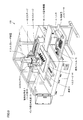
図9は、本実施の形態に従う形状測定装置を備えた塗布装置100の全体構成を示す斜視図である。塗布装置100は、基板9の主面上に透明のインク(液状材料)を複数層に亘って塗布可能に構成されている。図9を参照して、塗布装置100は、観察光学系2、CCDカメラ4、カット用レーザ装置8、インク塗布機構50、およびインク硬化用光源20から構成される塗布ヘッド部と、この塗布ヘッド部を塗布対象の基板9に対して垂直方向(Z軸方向)に移動させるZステージ40と、Zステージ40を搭載してX軸方向に移動させるXステージ42と、基板9を搭載してY軸方向に移動させるYステージ44と、装置全体の動作を制御する制御用コンピュータ70と、CCDカメラ4によって撮影された画像などを表示するモニタ74と、制御用コンピュータ70に作業者からの指令を入力するための操作パネル72とを備える。
観察光学系2は、照明用の光源(図1の照明装置1)を含み、基板9の表面状態や、インク塗布機構50によって塗布されたインクの状態を観察する。観察光学系2によって観察される画像は、CCDカメラ4により電気信号に変換され、モニタ74に表示される。カット用レーザ装置8は、観察光学系2を介して基板9上の不要部にレーザ光を照射して除去する。
インク塗布機構50は、基板9の主面上にインクを塗布する。インク硬化用光源20は、たとえばCO2レーザを含み、インク塗布機構50によって塗布されたインクにレーザ光を照射して硬化させる。
なお、この装置構成は一例であり、たとえば、観察光学系2などを搭載したZステージ40をXステージに搭載し、さらにXステージをYステージに搭載し、Zステージ40をXY方向に移動可能とするガントリー方式と呼ばれる構成でもよく、観察光学系2などを搭載したZステージ40を、対象の基板9に対してXY方向に相対的に移動可能な構成であればどのような構成でもよい。
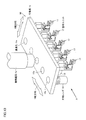
次に、複数の塗布針を用いたインク塗布機構50の例について説明する。図10は、観察光学系2およびインク塗布機構50の要部を示す斜視図である。図10を参照して、この塗布装置100は、可動板15と、倍率の異なる複数(たとえば5個)の対物レンズ19と、異なる材質からなるインクを塗布するための複数(たとえば5個)の塗布ユニット17とを備える。
可動板15は、観察光学系2の観察鏡筒2aの下端と基板9との間で、X軸方向およびY軸方向に移動可能に設けられている。また、可動板15には、たとえば5個の貫通孔15aが形成されている。
対物レンズ19は、Y軸方向に所定の間隔で、それぞれ貫通孔15aに対応するように可動板15の下面に固定されている。5個の塗布ユニット17は、それぞれ5個の対物レンズ19に隣接して配置されている。可動板15を移動させることにより、所望の塗布ユニット17を対象の基板9の上方に配置することが可能となっている。
図11(a)~(c)は、図10のA方向から要部を見た図であって、インク塗布動作を示す図である。塗布ユニット17は、塗布針170とインクタンク172とを含む。まず図11(a)に示すように、所望の塗布ユニット17の塗布針170を対象の基板9の上方に位置決めする。このとき、塗布針170の先端部は、インクタンク172内のインク内に浸漬されている。
次いで図11(b)に示すように、塗布針170を下降させてインクタンク172の底の孔から塗布針170の先端部を突出させる。このとき、塗布針170の先端部にはインクが付着している。次に図11(c)に示すように、塗布針170およびインクタンク172を下降させて塗布針170の先端部を基板9に接触させ、基板9にインクを塗布する。この後、図11(a)の状態に戻る。
複数の塗布針を用いたインク塗布機構は、この他にも様々な技術が知られているため詳細な説明を省略する。たとえば特許文献1などに示されている。塗布装置100は、たとえば図10に示すような機構をインク塗布機構50として用いることにより、複数のインクのうちの所望のインクを塗布することができ、また、複数の塗布針のうち所望の塗布径の塗布針を用いてインクを塗布することができる。
本実施の形態に従う形状測定装置のヘッド部10(図1)は、たとえば塗布装置100の観察光学系2に設けられている。制御用コンピュータ70は、インク塗布機構50を制御してインク塗布動作を行なった後、Zステージ40を移動させることによってヘッド部10をインク塗布部の表面の上方の所定の位置に位置決めする。制御用コンピュータ70はさらに、Zステージ40を基板9に対して相対的に移動させながら、CCDカメラ4により干渉光の画像を撮影する。制御用コンピュータ70は、画素ごとに干渉光強度がピークとなるZステージ位置を検出し、検出したZステージ位置を用いてインク塗布部の膜厚または凹凸部の高さを算出する。
[インク塗布動作の説明]
次に図12~16を用いて、塗布装置100で実行されるインク塗布動作の詳細について説明する。
次に図12~16を用いて、塗布装置100で実行されるインク塗布動作の詳細について説明する。
塗布装置100は、Zステージ40を用いてミロー型干渉計3を対象物に対して相対的に移動させ、実施の形態1で示した方法で自動的に焦点を検出し、検出した焦点位置を基準としてインク塗布動作を行う。
ミロー型干渉計3で生成される干渉縞は、検出対象とする面に焦点が合ったとき出現する。そのため、塗布動作の高さ方向の基準面として、たとえばガラスの表面や金属薄膜、クロム膜など凹凸のない滑らな面を用いた場合に焦点を合わせる際に有効である。電子部品の実装工程などで塗布装置100を用いる場合、塗布動作の高さ方向の基準面として金属薄膜などの滑らかな面が選択されることがある。
また、図5に示すように、分離度の山型波形の山裾の幅は数μmと小さくピークが明確に現れるため、焦点位置を高精度に検出することができる。
ここでは、図12に示すように、基板9上の金属薄膜91の表面上の領域ARを高さ方向の基準面とし、塗布部92にインクを塗布する場合の動作の例について説明する。なお、金属薄膜91と塗布部92は同じ高さとする。
塗布部92と塗布針170の先端とのオフセット量を予め求めておき、塗布装置100の制御用コンピュータ70に保存する。オフセット量は、次のように求める。
制御用コンピュータ70は、図13に示すように、基準面である金属薄膜91の表面に設定した領域ARに、実施の形態1に示す方法で焦点を合わせる。具体的には、領域ARの画素について輝度ヒストグラムを求め、当該輝度ヒストグラムに基づいて分離度Rを計算し、自動焦点動作を実行する。
次に、制御用コンピュータ70は、塗布装置100のインク塗布機構50の可動板15を図10のX軸方向またはY軸方向に移動して塗布針170を塗布部92の上方に移動する。この後、図14に示すように、制御用コンピュータ70は、Zステージ40をΔzだけ下降させた後、インク塗布機構50を制御して図11で説明した塗布動作を実行し、可動板15を元の位置まで戻す。
塗布装置100のモニタ74を確認し、塗布部92にインクが塗布されていない場合は、Δzを変更し、上記の手順を再度実行する。この操作を塗布部92にインクが塗布されるまで繰り返し、初めて塗布されたときのΔzを制御用コンピュータ70に保存する。
実際の塗布動作では、実施の形態1に示す方法を用いて、基準面である金属薄膜91の表面に焦点を合わせた後、塗布装置100のインク塗布機構50の可動板15を図10のX軸方向またはY軸方向に移動して塗布針170を塗布部92の上方に移動する。その後、Zステージ40をΔzだけ下降させた後、インク塗布機構50を制御して塗布動作を実行し、可動板15を元の位置まで戻す。
以上の説明では、金属薄膜91と塗布部92は同じ高さとして説明したが、図15に示すように、金属薄膜91よりも塗布部92の方が高い場合は、それらの段差ΔdをΔzから引いた(Δz-Δd)だけZステージ40を移動させる。また、図16に示すように、金属薄膜91よりも塗布部92の方が低い場合は、段差ΔdをΔzに加えた(Δz+Δd)だけZステージ40を移動させる。なお、ここではZステージ40が下降する方向をプラスとした。
[膜厚検査方法の説明]
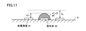
上述の方法で、塗布部92にインクを塗布した後、塗布したインクの膜厚を検査する。膜厚を測定する方法として、たとえば特開2015-007564号公報に記載の方法を用いて表面形状を測定することができる。図17に示すように、金属薄膜91と塗布したインク94の頂点部との段差Δtを求める。
上述の方法で、塗布部92にインクを塗布した後、塗布したインクの膜厚を検査する。膜厚を測定する方法として、たとえば特開2015-007564号公報に記載の方法を用いて表面形状を測定することができる。図17に示すように、金属薄膜91と塗布したインク94の頂点部との段差Δtを求める。
求めた段差Δtが、予め塗布装置100の制御用コンピュータ70に保存された下限値TLよりも小さい場合、再度インクを塗布する。このとき、塗布したインクの膜厚をΔtとおくと、Zステージ40のオフセット量を(Δz-Δt)としてインクを塗布する。この動作を、インクの膜厚Δtが下限値TLを超過するまで繰り返し実行する。ただし、塗布回数iをカウントし、iが予め指定した最大回数Nを超えたときは塗布動作を中断する。
塗布動作を中断したときは、作業者がモニタ74で塗布部92の状態を確認し、塗布が正しく実行されたか否かを判定する。
図18は、制御用コンピュータ70で実行される膜厚検査処理を説明するためのフローチャートである。
図18を参照して、塗布動作の実行が開始されると、制御用コンピュータ70は、ステップ(以下、ステップをSと略す。)S100にて、図12の金属薄膜91のような予め定められた基準面に対して焦点を合わせる(図13)。この時の基準面までの焦点距離と、予め設定されている対物レンズ19と塗布針170との高さ方向のオフセットに基づいて、制御用コンピュータ70は、基準面から塗布針170の先端までの高さΔzを算出する。
その後、制御用コンピュータ70は、Xステージ42およびYステージ44を動かして、塗布針170が、塗布部92の上方となるように移動する。
次に制御用コンピュータ70は、S110にて、塗布回数を示すカウンタiをi=1に初期化して処理をS120に進める。S120においては、制御用コンピュータ70は、カウンタiが所定の最大回数N以下であるか否かを判定する。
カウンタiが最大回数N以下(i≦N)の場合(S120にてYES)は、処理がS130に進められ、制御用コンピュータ70は、Zステージ40をΔzだけ下降させて、塗布部92に対してインクを塗布する(図14)。
その後、制御用コンピュータ70は、Zステージ40をΔzだけ上昇させて初期位置に戻し、さらに対物レンズ19が塗布部92の上方となるように位置決めする。そして、制御用コンピュータ70は、S140にて、Zステージ40を基板9に対して高さ方向に相対的に移動させながら、CCDカメラ4により干渉光の画像を撮影し、干渉光強度がピークとなるZステージ40の位置から、塗布されたインクの頂点部の基準面からの高さ(膜厚)Δtを測定する(図17)。
制御用コンピュータ70は、S150にて、測定したインク部の膜厚Δtが所定の下限値TL以上となっているか否か(Δt≧TL)を判定する。
膜厚Δtが下限値TL未満の場合(S150にてNO)は、塗布量が十分でないため、制御用コンピュータ70は、S160にてカウンタiをインクリメントして、処理をS120に戻して、再度塗布動作を実行する。この際、塗布針170の下降量は(Δz-Δt)に修正される。
なお、上記の塗布動作を繰り返し実行する過程において、カウンタiが予め指定した最大回数Nを超えた場合(i>N)(S120にてNO)は、制御用コンピュータ70は、塗布動作を中断する。
また、インク部の膜厚Δtが下限値TL以上となった場合(S150にてYES)は、塗布が完了したとして、制御用コンピュータ70は、塗布動作を終了する。
以上のように、本実施の形態に従う形状測定装置を用いて、上記の処理に従って塗布装置100を制御することによって、塗布されたインクの高さを精度よく、かつ、効率良く測定することができるので、作業効率を改善することができる。また、まず基準面に対して焦点を合わせた後に塗布動作を行なうようにすることで、塗布針と塗布部との位置関係が安定するので、塗布部に付着するインク量を安定させることができる。
さらに、塗布後の膜厚を測定し、当該膜厚が所定量を超えるまで繰り返し塗布動作を行なうことによって、塗布量不足による製品の不良を低減させることができる。また、不良品の補修の手間を省略することもできるので、製造タクトの向上が可能となる。
今回開示された実施の形態はすべての点で例示であって制限的なものではないと考えられるべきである。本発明の範囲は上記した説明ではなくて請求の範囲によって示され、請求の範囲と均等の意味および範囲内でのすべての変更が含まれることが意図される。
1 照明装置、2 観察光学系、2a 観察鏡筒、3 ミロー型干渉計、4 撮像装置、5 ピエゾステージ、6 制御装置、7 対象物、8 カット用レーザ装置、9 基板、10 ヘッド部、11 白色光源、12 フィルタ、15 可動板、15a 貫通孔、17 塗布ユニット、19,31 対物レンズ、20 インク硬化用光源、21 集光レンズ、22 ハーフミラー、23 結像レンズ、32 反射鏡、33 半透鏡、40 Zステージ、42 Xステージ、44 Yステージ、50 インク塗布機構、70 制御用コンピュータ、72 操作パネル、74 モニタ、91 金属薄膜、92 塗布部、94 インク、100 塗布装置、170 塗布針、172 インクタンク、A1~A3 光軸。
Claims (9)
- 対象物の表面形状を測定する形状測定装置であって、
照明装置から出射される白色光を第1および第2の光束に分離し、前記第1の光束を前記対象物の表面に照射するとともに前記第2の光束を参照面に照射し、前記対象物の表面からの反射光と前記参照面からの反射光とを合成し、前記対象物の表面形状に対応する干渉縞を生成する干渉計と、
前記干渉縞を観察するための観察光学系と、
前記観察光学系を介して前記干渉縞の画像を撮影する撮像装置と、
前記対象物および前記干渉計を光軸方向に相対移動させる第1の位置決め装置と、
前記撮像装置および前記第1の位置決め装置を制御し、前記干渉計の焦点を前記対象物の表面に合わせる第1の自動焦点動作を実行する制御装置とを備え、
前記制御装置は、前記第1の自動焦点動作では、前記対象物および前記干渉計を光軸方向に相対移動させながら複数の相対位置でそれぞれの画像を撮影し、各画像毎に当該画像に含まれる複数の画素の輝度分布図について判別分析法による分離度を求め、複数の画像のうちの前記分離度が最大になる画像に対応する相対位置に前記対象物および前記干渉計を配置する、形状測定装置。 - 前記判別分析法では、前記複数の画素の輝度分布図が輝度しきい値で2つのクラスに分離され、前記輝度しきい値は、クラス内分散が最小となり、かつクラス間分散が最大となるように設定され、前記クラス間分散と前記クラス内分散との比が前記分離度とされる、請求項1に記載の形状測定装置。
- 前記干渉計は、
前記対象物の表面に対向して設けられた対物レンズと、
前記対物レンズと前記対象物の表面との間に設けられた半透鏡と、
前記半透鏡に対向して前記対物レンズの中央部に設けられた前記参照面を有する反射鏡とを含むミロー型干渉計であり、
前記照明装置から出射された白色光は、前記対物レンズによって屈折されて前記半透鏡に入射し、前記半透鏡を透過した前記第1の光束と前記半透鏡で反射した前記第2の光束に分離され、
前記第1の光束が前記対象物の表面に照射されるとともに前記第2の光束が前記参照面に照射され、前記対象物の表面からの反射光と前記参照面からの反射光とが前記半透鏡で合成されて干渉光となり、前記干渉光によって前記干渉縞が生成され、
前記ミロー型干渉計の光軸および焦点は、それぞれ前記対物レンズの光軸および焦点である、請求項1または請求項2に記載の形状測定装置。 - さらに、前記対象物に対して前記干渉計を光軸方向に相対移動させる第2の位置決め装置を備え、
前記第2の位置決め装置のストロークは前記第1の位置決め装置のストロークよりも大きく、
前記制御装置は、
前記第1の自動焦点動作を実行する前に、前記撮像装置および前記第2の位置決め装置を制御して前記干渉計の焦点の位置を粗調整する第2の自動焦点動作を実行し、
前記第2の自動焦点動作では、前記対象物および前記干渉計を光軸方向に相対移動させながら複数の相対位置でそれぞれの画像を撮影し、各画像毎に当該画像に含まれる複数の画素の輝度の微分値を求め、複数の画像のうちの前記微分値が最大になる画像に対応する相対位置に前記対象物および前記干渉計を配置する、請求項1から請求項3のいずれか1項に記載の形状測定装置。 - 前記第1の位置決め装置は、前記観察光学系に固定されて前記干渉計を移動させ、
少なくとも前記第1の位置決め装置、前記観察光学系、および前記干渉計は1つの光学ユニットを構成しており、
前記第2の位置決め装置は前記光学ユニットを移動させる、請求項4に記載の形状測定装置。 - 対象物の表面に液状材料を塗布する塗布装置であって、
塗布針を有し前記塗布針の先端部に付着した液状材料を前記対象物の表面に塗布する塗布ユニットと、
照明装置から出射される白色光を第1および第2の光束に分離し、前記第1の光束を前記対象物の表面に照射するとともに前記第2の光束を参照面に照射し、前記対象物の表面からの反射光と前記参照面からの反射光とを合成し、前記対象物の表面形状に対応する干渉縞を生成する干渉計と、前記干渉縞を観察するための観察光学系と、前記観察光学系を介して前記干渉縞の画像を撮影する撮像装置と、前記対象物および前記干渉計を光軸方向に相対移動させる第1の位置決め装置とを含んで構成されるヘッド部と、
前記ヘッド部と前記対象物とを前記光軸方向と直交する方向に相対移動させて前記ヘッド部を前記対象物の表面の上方の所望の位置に位置決めする第2の位置決め装置と、
前記撮像装置および前記第1および第2の位置決め装置を制御し、前記干渉計の焦点を前記対象物の表面に合わせる第1の自動焦点動作を実行する制御装置とを備え、
前記制御装置は、前記第1の自動焦点動作では、前記対象物および前記干渉計を光軸方向に相対移動させながら複数の相対位置でそれぞれ複数の画像を撮影し、各画像毎に当該画像に含まれる複数の画素の輝度分布図について判別分析法による分離度を求め、前記複数の画像のうちの前記分離度が最大になる画像に対応する相対位置に前記対象物および前記干渉計を配置する、塗布装置。 - 前記制御装置は、前記第1の自動焦点動作において、前記対象物上に設定した基準面に焦点を合わせた後、前記塗布針で前記対象物の表面に前記液状材料を塗布する、請求項6に記載の塗布装置。
- 前記制御装置は、前記液状材料を塗布した後、前記基準面と塗布した前記液状材料の頂点との段差を求め、求めた前記段差が予め設定された下限値を超えるまで塗布動作を繰り返す、請求項7に記載の塗布装置。
- 前記第2の位置決め装置のストロークは、前記第1の位置決め装置のストロークよりも大きく、
前記制御装置は、
前記第1の自動焦点動作を実行する前に、前記撮像装置および前記第2の位置決め装置を制御して前記干渉計の焦点の位置を粗調整する第2の自動焦点動作を実行し、
前記第2の自動焦点動作では、前記対象物および前記干渉計を光軸方向に相対移動させながら複数の相対位置でそれぞれの画像を撮影し、各画像毎に当該画像に含まれる複数の画素の輝度の微分値を求め、複数の画像のうちの前記微分値が最大になる画像に対応する相対位置に前記対象物および前記干渉計を配置する、請求項6から請求項8のいずれか1項に記載の塗布装置。
Priority Applications (1)
| Application Number | Priority Date | Filing Date | Title |
|---|---|---|---|
| CN201680035681.2A CN107709923B (zh) | 2015-06-18 | 2016-06-09 | 形状测定装置及搭载有形状测定装置的涂布装置 |
Applications Claiming Priority (4)
| Application Number | Priority Date | Filing Date | Title |
|---|---|---|---|
| JP2015122864 | 2015-06-18 | ||
| JP2015-122864 | 2015-06-18 | ||
| JP2016099617A JP6665028B2 (ja) | 2015-06-18 | 2016-05-18 | 形状測定装置およびそれを搭載した塗布装置 |
| JP2016-099617 | 2016-05-18 |
Publications (1)
| Publication Number | Publication Date |
|---|---|
| WO2016204062A1 true WO2016204062A1 (ja) | 2016-12-22 |
Family
ID=57545607
Family Applications (1)
| Application Number | Title | Priority Date | Filing Date |
|---|---|---|---|
| PCT/JP2016/067190 Ceased WO2016204062A1 (ja) | 2015-06-18 | 2016-06-09 | 形状測定装置およびそれを搭載した塗布装置 |
Country Status (1)
| Country | Link |
|---|---|
| WO (1) | WO2016204062A1 (ja) |
Cited By (2)
| Publication number | Priority date | Publication date | Assignee | Title |
|---|---|---|---|---|
| JP6333351B1 (ja) * | 2016-12-27 | 2018-05-30 | Ntn株式会社 | 測定装置、塗布装置、および膜厚測定方法 |
| EP4526619A1 (fr) | 2022-05-19 | 2025-03-26 | Sciences Et Techniques Industrielles De La Lumiere | Sonde interférométrique à faible encombrement |
Citations (4)
| Publication number | Priority date | Publication date | Assignee | Title |
|---|---|---|---|---|
| JP2000056210A (ja) * | 1998-08-07 | 2000-02-25 | Ntn Corp | オートフォーカス装置 |
| JP2005285898A (ja) * | 2004-03-29 | 2005-10-13 | Toppan Printing Co Ltd | パターン画像判定方法及びその方法を用いたパターン画像判定装置 |
| JP2007212268A (ja) * | 2006-02-09 | 2007-08-23 | Epson Imaging Devices Corp | 検査装置、電気光学装置用基板の検査方法及び電気光学装置用基板の製造方法 |
| JP2015007564A (ja) * | 2013-06-25 | 2015-01-15 | Ntn株式会社 | 塗布装置および高さ検出方法 |
-
2016
- 2016-06-09 WO PCT/JP2016/067190 patent/WO2016204062A1/ja not_active Ceased
Patent Citations (4)
| Publication number | Priority date | Publication date | Assignee | Title |
|---|---|---|---|---|
| JP2000056210A (ja) * | 1998-08-07 | 2000-02-25 | Ntn Corp | オートフォーカス装置 |
| JP2005285898A (ja) * | 2004-03-29 | 2005-10-13 | Toppan Printing Co Ltd | パターン画像判定方法及びその方法を用いたパターン画像判定装置 |
| JP2007212268A (ja) * | 2006-02-09 | 2007-08-23 | Epson Imaging Devices Corp | 検査装置、電気光学装置用基板の検査方法及び電気光学装置用基板の製造方法 |
| JP2015007564A (ja) * | 2013-06-25 | 2015-01-15 | Ntn株式会社 | 塗布装置および高さ検出方法 |
Cited By (5)
| Publication number | Priority date | Publication date | Assignee | Title |
|---|---|---|---|---|
| JP6333351B1 (ja) * | 2016-12-27 | 2018-05-30 | Ntn株式会社 | 測定装置、塗布装置、および膜厚測定方法 |
| JP2018105781A (ja) * | 2016-12-27 | 2018-07-05 | Ntn株式会社 | 測定装置、塗布装置、および膜厚測定方法 |
| WO2018123398A1 (ja) * | 2016-12-27 | 2018-07-05 | Ntn株式会社 | 測定装置、塗布装置、および膜厚測定方法 |
| US10845185B2 (en) | 2016-12-27 | 2020-11-24 | Ntn Corporation | Measuring apparatus and method for measuring film thickness using relative heights in combination with refractive index |
| EP4526619A1 (fr) | 2022-05-19 | 2025-03-26 | Sciences Et Techniques Industrielles De La Lumiere | Sonde interférométrique à faible encombrement |
Similar Documents
| Publication | Publication Date | Title |
|---|---|---|
| JP6749814B2 (ja) | 高さ検出装置およびそれを搭載した塗布装置 | |
| CN106662431B (zh) | 形状测定装置、涂敷装置及形状测定方法 | |
| JP6522344B2 (ja) | 高さ検出装置、塗布装置および高さ検出方法 | |
| US10521895B2 (en) | Dynamic automatic focus tracking system | |
| JP6481843B1 (ja) | レーザ加工装置及びその制御方法 | |
| JP6333351B1 (ja) | 測定装置、塗布装置、および膜厚測定方法 | |
| JP6680552B2 (ja) | 形状測定装置および被塗布対象物の製造方法 | |
| JP6665028B2 (ja) | 形状測定装置およびそれを搭載した塗布装置 | |
| JP5096852B2 (ja) | 線幅測定装置および線幅測定装置の検査方法 | |
| WO2016204062A1 (ja) | 形状測定装置およびそれを搭載した塗布装置 | |
| US11326871B2 (en) | Height detection apparatus and coating apparatus equipped with the same | |
| KR101873602B1 (ko) | 칩 다이의 피킹 및 배치를 위한 시스템 및 방법 | |
| JP6415948B2 (ja) | 形状等測定装置 | |
| JP2014121727A (ja) | レーザ加工装置 | |
| KR100922625B1 (ko) | 입체 형상 측정 방법 | |
| JP2023184135A (ja) | 塗布装置および塗布方法 | |
| KR20260028420A (ko) | 웨이퍼 검사 장치 및 웨이퍼 검사 방법 | |
| JP2007334213A (ja) | パターン欠陥修正装置およびパターン欠陥修正方法 | |
| WO2016204061A1 (ja) | 液状材料塗布装置 |
Legal Events
| Date | Code | Title | Description |
|---|---|---|---|
| 121 | Ep: the epo has been informed by wipo that ep was designated in this application |
Ref document number: 16811537 Country of ref document: EP Kind code of ref document: A1 |
|
| NENP | Non-entry into the national phase |
Ref country code: DE |
|
| 122 | Ep: pct application non-entry in european phase |
Ref document number: 16811537 Country of ref document: EP Kind code of ref document: A1 |