WO2016203635A1 - 無停電電源装置 - Google Patents
無停電電源装置 Download PDFInfo
- Publication number
- WO2016203635A1 WO2016203635A1 PCT/JP2015/067696 JP2015067696W WO2016203635A1 WO 2016203635 A1 WO2016203635 A1 WO 2016203635A1 JP 2015067696 W JP2015067696 W JP 2015067696W WO 2016203635 A1 WO2016203635 A1 WO 2016203635A1
- Authority
- WO
- WIPO (PCT)
- Prior art keywords
- power
- terminal
- power supply
- converter
- bidirectional
- Prior art date
- Legal status (The legal status is an assumption and is not a legal conclusion. Google has not performed a legal analysis and makes no representation as to the accuracy of the status listed.)
- Ceased
Links
Images








Classifications
-
- H—ELECTRICITY
- H02—GENERATION; CONVERSION OR DISTRIBUTION OF ELECTRIC POWER
- H02J—ELECTRIC POWER NETWORKS; CIRCUIT ARRANGEMENTS OR SYSTEMS FOR SUPPLYING OR DISTRIBUTING ELECTRIC POWER; SYSTEMS FOR STORING ELECTRIC ENERGY
- H02J9/00—Circuit arrangements for emergency or stand-by power supply, e.g. for emergency lighting
- H02J9/04—Circuit arrangements for emergency or stand-by power supply, e.g. for emergency lighting in which the distribution system is disconnected from the normal source and connected to a standby source
- H02J9/06—Circuit arrangements for emergency or stand-by power supply, e.g. for emergency lighting in which the distribution system is disconnected from the normal source and connected to a standby source with automatic change-over, e.g. UPS systems
- H02J9/062—Circuit arrangements for emergency or stand-by power supply, e.g. for emergency lighting in which the distribution system is disconnected from the normal source and connected to a standby source with automatic change-over, e.g. UPS systems for AC powered loads
-
- H—ELECTRICITY
- H02—GENERATION; CONVERSION OR DISTRIBUTION OF ELECTRIC POWER
- H02M—APPARATUS FOR CONVERSION BETWEEN AC AND AC, BETWEEN AC AND DC, OR BETWEEN DC AND DC, AND FOR USE WITH MAINS OR SIMILAR POWER SUPPLY SYSTEMS; CONVERSION OF DC OR AC INPUT POWER INTO SURGE OUTPUT POWER; CONTROL OR REGULATION THEREOF
- H02M5/00—Conversion of AC power input into AC power output, e.g. for change of voltage, for change of frequency, for change of number of phases
- H02M5/02—Conversion of AC power input into AC power output, e.g. for change of voltage, for change of frequency, for change of number of phases without intermediate conversion into DC
- H02M5/04—Conversion of AC power input into AC power output, e.g. for change of voltage, for change of frequency, for change of number of phases without intermediate conversion into DC by static converters
- H02M5/22—Conversion of AC power input into AC power output, e.g. for change of voltage, for change of frequency, for change of number of phases without intermediate conversion into DC by static converters using discharge tubes with control electrode or semiconductor devices with control electrode
- H02M5/275—Conversion of AC power input into AC power output, e.g. for change of voltage, for change of frequency, for change of number of phases without intermediate conversion into DC by static converters using discharge tubes with control electrode or semiconductor devices with control electrode using devices of a triode or transistor type requiring continuous application of a control signal
- H02M5/293—Conversion of AC power input into AC power output, e.g. for change of voltage, for change of frequency, for change of number of phases without intermediate conversion into DC by static converters using discharge tubes with control electrode or semiconductor devices with control electrode using devices of a triode or transistor type requiring continuous application of a control signal using semiconductor devices only
-
- H—ELECTRICITY
- H02—GENERATION; CONVERSION OR DISTRIBUTION OF ELECTRIC POWER
- H02M—APPARATUS FOR CONVERSION BETWEEN AC AND AC, BETWEEN AC AND DC, OR BETWEEN DC AND DC, AND FOR USE WITH MAINS OR SIMILAR POWER SUPPLY SYSTEMS; CONVERSION OF DC OR AC INPUT POWER INTO SURGE OUTPUT POWER; CONTROL OR REGULATION THEREOF
- H02M5/00—Conversion of AC power input into AC power output, e.g. for change of voltage, for change of frequency, for change of number of phases
- H02M5/40—Conversion of AC power input into AC power output, e.g. for change of voltage, for change of frequency, for change of number of phases with intermediate conversion into DC
- H02M5/42—Conversion of AC power input into AC power output, e.g. for change of voltage, for change of frequency, for change of number of phases with intermediate conversion into DC by static converters
- H02M5/44—Conversion of AC power input into AC power output, e.g. for change of voltage, for change of frequency, for change of number of phases with intermediate conversion into DC by static converters using discharge tubes or semiconductor devices to convert the intermediate DC into AC
- H02M5/453—Conversion of AC power input into AC power output, e.g. for change of voltage, for change of frequency, for change of number of phases with intermediate conversion into DC by static converters using discharge tubes or semiconductor devices to convert the intermediate DC into AC using devices of a triode or transistor type requiring continuous application of a control signal
- H02M5/458—Conversion of AC power input into AC power output, e.g. for change of voltage, for change of frequency, for change of number of phases with intermediate conversion into DC by static converters using discharge tubes or semiconductor devices to convert the intermediate DC into AC using devices of a triode or transistor type requiring continuous application of a control signal using semiconductor devices only
- H02M5/4585—Conversion of AC power input into AC power output, e.g. for change of voltage, for change of frequency, for change of number of phases with intermediate conversion into DC by static converters using discharge tubes or semiconductor devices to convert the intermediate DC into AC using devices of a triode or transistor type requiring continuous application of a control signal using semiconductor devices only having a rectifier with controlled elements
-
- H—ELECTRICITY
- H02—GENERATION; CONVERSION OR DISTRIBUTION OF ELECTRIC POWER
- H02M—APPARATUS FOR CONVERSION BETWEEN AC AND AC, BETWEEN AC AND DC, OR BETWEEN DC AND DC, AND FOR USE WITH MAINS OR SIMILAR POWER SUPPLY SYSTEMS; CONVERSION OF DC OR AC INPUT POWER INTO SURGE OUTPUT POWER; CONTROL OR REGULATION THEREOF
- H02M7/00—Conversion of AC power input into DC power output; Conversion of DC power input into AC power output
- H02M7/42—Conversion of DC power input into AC power output without possibility of reversal
- H02M7/44—Conversion of DC power input into AC power output without possibility of reversal by static converters
- H02M7/48—Conversion of DC power input into AC power output without possibility of reversal by static converters using discharge tubes with control electrode or semiconductor devices with control electrode
- H02M7/53—Conversion of DC power input into AC power output without possibility of reversal by static converters using discharge tubes with control electrode or semiconductor devices with control electrode using devices of a triode or transistor type requiring continuous application of a control signal
- H02M7/537—Conversion of DC power input into AC power output without possibility of reversal by static converters using discharge tubes with control electrode or semiconductor devices with control electrode using devices of a triode or transistor type requiring continuous application of a control signal using semiconductor devices only, e.g. single switched pulse inverters
- H02M7/5387—Conversion of DC power input into AC power output without possibility of reversal by static converters using discharge tubes with control electrode or semiconductor devices with control electrode using devices of a triode or transistor type requiring continuous application of a control signal using semiconductor devices only, e.g. single switched pulse inverters in a bridge configuration
Definitions
- the present invention relates to an uninterruptible power supply, and more particularly to an uninterruptible power supply capable of continuing load operation even during a power failure.
- the power supply method of the uninterruptible power supply includes a constant inverter power supply method and a constant commercial power supply method (see Japanese Patent Application Laid-Open No. 2011-223731 (Patent Document 1)).
- a constant inverter power supply system during normal times when AC power is supplied from a commercial AC power supply, AC power from the commercial AC power supply is converted into DC power by a converter, and the DC power is transferred to the power storage device. In addition to being stored, it is converted into AC power by an inverter and supplied to a load. In the event of a power failure when the supply of AC power from the commercial AC power supply is stopped, the DC power of the power storage device is converted into AC power by the inverter and supplied to the load.
- uninterruptible power supply In a normal commercial power supply uninterruptible power supply, normally, AC power from a commercial AC power supply is supplied to a load and a bidirectional power converter via a high-speed switch, and converted to DC power by the bidirectional power converter. Stored in the electricity storage store. At the time of a power failure, the high-speed switch is turned off, and the DC power of the power storage device is converted into AC power by the bidirectional power converter and supplied to the load.
- the continuous power supply type uninterruptible power supply has the advantage of high reliability because even if a power failure occurs, AC power can be continuously supplied to the load by the inverter without interruption.
- this uninterruptible power supply has the disadvantages that loss is always generated in the inverter and efficiency is low because AC power is supplied to the load by the inverter even during normal times.
- the uninterruptible power supply of the commercial power supply system has the advantages that the loss is small and the efficiency is high because power is normally supplied to the load via a high-speed switch.
- the high-speed switch is turned off and the DC-AC conversion operation of the bidirectional power converter is started.
- the reliability is low.
- an uninterruptible power supply using a constant inverter power supply system has been introduced as a server power supply where reliability is more important than efficiency, and commercial power is always used as an air conditioner power supply where efficiency is more important than reliability.
- a power supply uninterruptible power supply is introduced.
- two uninterruptible power supplies are installed, there is a problem that a large installation space is required and the cost is increased.
- a main object of the present invention is to provide an uninterruptible power supply capable of supplying power to two loads by a constant inverter power supply method and a constant commercial power supply method, respectively.
- the uninterruptible power supply includes a first terminal that receives AC power from a commercial AC power supply, a second terminal connected to the power storage device, and a third terminal connected to the first load.
- a fourth terminal connected to the second load, a first uninterruptible power supply connected to the first to third terminals, and connected to the first, second and fourth terminals And a second uninterruptible power supply unit.
- the first uninterruptible power supply unit converts the AC power from the commercial AC power source into DC power during normal times when AC power is supplied from the commercial AC power source, stores the DC power in the power storage device, and stores the AC power.
- the DC power of the power storage device is converted to AC power and supplied to the load.
- the second uninterruptible power supply unit supplies the AC power from the commercial AC power source to the second load during normal times, and converts the DC power of the power storage device into AC power during the power failure to convert the second load. To supply.
- a first terminal that receives AC power from a commercial AC power supply, a second terminal connected to the power storage device, and a third terminal connected to the first load , A fourth terminal connected to the second load, a first uninterruptible power supply unit of a constant inverter power supply system connected to the first to third terminals, the first, second, and fourth A second commercial uninterruptible power supply unit connected to the terminal is provided. Therefore, it is possible to supply power to the first and second loads by the constant inverter power supply method and the constant commercial power supply method, respectively.
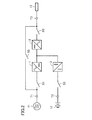
- FIG. 3 is a circuit block diagram illustrating a comparative example of the first embodiment.
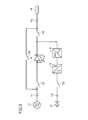
- FIG. FIG. 6 is a circuit block diagram illustrating another comparative example of the first embodiment. It is a circuit block diagram for demonstrating the problem of the uninterruptible power supply shown in FIG.
- FIG. 5 is a circuit diagram for explaining the problem described in FIG. 4 in detail.
- FIG. 10 is a circuit diagram showing a modification of the second embodiment.
- FIG. 10 is a circuit diagram showing another modification of the second embodiment.
- FIG. 10 is a circuit diagram showing a modification of the third embodiment. It is a circuit diagram which shows the structure of the uninterruptible power supply by Embodiment 4 of this invention.
- FIG. 10 is a circuit diagram showing a modification of the fourth embodiment. It is a circuit block diagram which shows the structure of the uninterruptible power supply by Embodiment 5 of this invention. It is a circuit diagram for demonstrating the problem of the uninterruptible power supply shown in FIG. It is a circuit diagram which shows the structure of the uninterruptible power supply by Embodiment 6 of this invention. It is a circuit diagram which shows the structure of the uninterruptible power supply by Embodiment 7 of this invention. It is a circuit block diagram which shows the structure of the uninterruptible power supply by Embodiment 8 of this invention.
- FIG. 1 is a circuit block diagram showing a configuration of an uninterruptible power supply according to Embodiment 1 of the present invention.
- this uninterruptible power supply includes an AC input terminal (first terminal) T1, a battery terminal (second terminal) T2, an AC output terminal (third terminal) T3, an AC output terminal (fourth terminal).
- Terminal) T4 switches S1 to S6, converter 1, inverter 2, bidirectional choppers 3 and 6, high-speed switch 4, and bidirectional power converter 5.
- the converter 1, the inverter 2, and the bidirectional chopper 3 constitute a first uninterruptible power supply unit of a constant inverter feeding method.
- the high-speed switch 4, the bidirectional power converter 5, and the bidirectional chopper 6 constitute a second uninterruptible power supply unit that is always in a commercial power supply system.
- this uninterruptible power supply actually receives three-phase AC power and outputs three-phase AC power, only the circuit for one phase is shown in FIG. 1 for simplification of the drawing and explanation. Has been.
- the AC input terminal T1 receives AC power having a commercial frequency from the commercial AC power supply 11.
- the battery terminal T ⁇ b> 2 is connected to the battery (power storage device) 12.
- the battery 12 stores DC power.
- a capacitor may be connected instead of the battery 12.
- the AC output terminal T3 is used to output AC power in a constant inverter power supply system, and is connected to the load 13.
- the load 13 is a server, for example, and is driven by AC power having a commercial frequency.
- the AC output terminal T4 is used for outputting AC power in a constant commercial power supply system, and is connected to the load 14.
- the load 14 is an air conditioner, for example, and is driven by AC power having a commercial frequency.
- the one terminal of the switch S1 is connected to the AC input terminal T1, and the other terminal is connected to the input node of the converter 1 and one terminal of the high-speed switch 4.
- One terminal of the switch S2 is connected to the battery terminal T2, and the other terminal is connected to the bidirectional choppers 3 and 6.
- the switch S3 is connected between the output node of the inverter 2 and the AC output terminal T3.
- One terminal of the switch S4 is connected to the other terminal of the high-speed switch 4 and the bidirectional power converter 5, and the other terminal of the switch S4 is connected to the AC output terminal T4.
- the switch S5 is connected between the AC input terminal T1 and the AC output terminal T3.
- the switch S6 is connected between the AC input terminal T1 and the AC output terminal T4.
- switches S1 to S4 are turned off and switches S5 and S6 are turned on.
- commercial AC power supply 11 and converter 1 and high-speed switch 4 are electrically disconnected
- battery 12 and bidirectional choppers 3 and 6 are electrically disconnected
- inverter 2 and load 13 are electrically disconnected.
- the high speed switch 4 and the bidirectional power converter 5 are electrically disconnected from the load 14.
- the converter 1, the inverter 2, the bidirectional choppers 3 and 6, the bidirectional power converter 5, and the battery 12 can be inspected, repaired, and replaced.
- AC power is supplied from the commercial AC power supply 11 to the loads 13 and 14 via the switches S5 and S6, and the loads 13 and 14 are operated.
- the switches S1 to S4 When operating the uninterruptible power supply, the switches S1 to S4 are turned on and the switches S5 and S6 are turned off. Thereby, AC power is supplied from the commercial AC power supply 11 to the converter 1 and the high-speed switch 4, the battery 12 and the bidirectional choppers 3 and 6 are connected, the inverter 2 and the load 13 are connected, and the high-speed switch and bidirectional power conversion. The device 5 and the load 14 are connected. In the following description, it is assumed that the switches S1 to S4 are turned on and the switches S5 and S6 are turned off.
- the converter 1 converts AC power supplied from the commercial AC power supply 11 via the switch S1 into DC power during normal times when AC power is supplied from the commercial AC power supply 11. At the time of a power failure when the supply of AC power from the commercial AC power supply 11 is stopped, the operation of the converter 1 is stopped.
- the output node of the converter 1 is connected to the input node of the inverter 2 and the bidirectional chopper 3.
- the inverter 2 normally converts the DC power generated by the converter 1 into AC power and supplies the AC power to the load 13 via the switch S3. In the event of a power failure, the inverter 2 converts the DC power supplied from the battery 12 via the switch S2 and the bidirectional chopper 3 into AC power, and supplies the AC power to the load 13 via the switch S3.
- the bidirectional chopper 3 normally stores DC power generated by the converter 1 in the battery 12 via the switch S2 and supplies DC power supplied from the battery 12 via the switch S2 to the inverter 2 during a power failure. To do.
- the high speed switch 4 is normally turned on and turned off at the time of a power failure.
- FIG. 1 shows a case where the high-speed switch 4 is configured by two thyristors connected in antiparallel to each other.
- the high-speed switch 4 may be configured by a semiconductor switch (for example, a transistor) other than a thyristor, or may be configured by a mechanical switch capable of high-speed operation.
- the bi-directional power converter 5 is connected between the other terminal of the high-speed switch 4 and the bi-directional chopper 6, and normally, AC power supplied from the commercial AC power supply 11 via the high-speed switch 4 is converted into DC power.
- the DC power is converted and applied to the bidirectional chopper 6, and at the time of a power failure, the DC power supplied from the bidirectional chopper 6 is converted into AC power and supplied to the load 14 via the switch S4.
- the bidirectional chopper 6 stores the DC power generated by the bidirectional power converter 5 in the battery 12 via the switch S2 in the normal time, and stores the DC power of the battery 12 in the bidirectional power converter 5 in the event of a power failure. Supply.
- AC power from the commercial AC power supply 11 is supplied to the load 14 via the high-speed switch 4, and the load 14 is operated.
- the AC power from the commercial AC power supply 11 is also supplied to the bidirectional power converter 5 via the high-speed switch 4 and is converted into DC power by the bidirectional power converter 5, and the DC power is passed through the bidirectional chopper 6. It is stored in the battery 12.
- the high-speed switch 4 is turned off to electrically disconnect the commercial AC power supply 11 and the load 13, and the DC power of the battery 12 is supplied to the bidirectional power converter 5 by the bidirectional chopper 6. 5 is converted into AC power and supplied to the load 14. Therefore, the operation of the loads 13 and 14 is continued during the period in which the DC power is stored in the battery 12.
- AC power can be supplied to the load 13 by a constant inverter power supply system and AC power can be supplied to the load 14 by a constant commercial power supply system by a single uninterruptible power supply. Therefore, compared with the case where a constant inverter power supply type uninterruptible power supply unit and a constant commercial power supply type uninterruptible power supply unit are provided separately, the device can be made smaller, lower in cost, simplified in configuration, and reduced in installation space. Can be planned.
- FIG. 2 is a circuit block diagram showing a comparative example of the first embodiment, and is a diagram contrasted with FIG. Referring to FIG. 2, this uninterruptible power supply removes AC output terminal T4, switches S4 and S6, high-speed switch 4, bidirectional power converter 5, and bidirectional chopper 6 from the uninterruptible power supply of FIG. The AC power is always supplied to the load 13 by the inverter feeding method.
- FIG. 3 is a circuit block diagram showing another comparative example of the first embodiment, and is a diagram contrasted with FIG. Referring to FIG. 3, this uninterruptible power supply device is obtained by removing AC output terminal T3, switches S3 and S5, converter 1, inverter 2, and bidirectional chopper 3 from the uninterruptible power supply device of FIG. AC power is supplied to the load 14 by a constant commercial power supply system.
- the uninterruptible power supply of FIG. 2 includes a battery 12, four switches S1 to S3, S5, a cooling fan (not shown), a housing (not shown) for housing them.
- the uninterruptible power supply of FIG. 3 includes a battery 12, four switches S1, S2, S4, S6, a cooling fan (not shown), a casing (not shown) that houses them, and the like.
- the uninterruptible power supply device of FIG. 1 includes a battery 12, six switches S1 to S6, a cooling fan (not shown), a housing (not shown) that accommodates them.
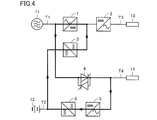
- FIG. 4 is a circuit block diagram for explaining the problem of the uninterruptible power supply shown in FIG.
- the switches S1 to S6 are not shown, and the case where the switches S1 to S4 are turned on and the switches S5 and S6 are turned off is shown.
- a circulating circuit is formed by the converter 1, the high-speed switch 4, the bidirectional power converter 5, the bidirectional chopper 6, and the bidirectional chopper 3, as shown in FIG. , Circulating current may flow.
- Circulating current may flow.
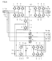
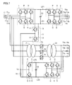
- FIG. 5 is a circuit diagram showing in more detail the configuration of the uninterruptible power supply shown in FIG.
- this uninterruptible power supply actually receives the three-phase AC power from the commercial AC power supply 11
- three AC input terminals T1a to T1c are provided, and the three-phase AC power is always output by the inverter feeding method. Therefore, three AC output terminals T3a to T3c are provided, and three AC output terminals T4a to T4c are provided in order to always output three-phase AC power by a commercial power supply method.
- the AC output terminals T3a to T3c are connected to one terminals of loads 13a to 13c driven by three-phase AC power.
- the other terminals of the loads 13a to 13c are connected to each other.
- Loads 14a to 14c driven by three-phase AC power are connected to AC output terminals T4a to T4c.
- the other terminals of the loads 13a to 13c are connected to each other.
- Converter 1 includes three sets of transistor P and diode D, and three sets of transistor Q and diode D.
- the collectors of the three transistors P are all connected to a DC positive bus LP1, and their emitters are connected to AC input terminals T1a to T1c via three switches S1 (not shown).
- the collectors of the three transistors Q are connected to the emitters of the three transistors P, respectively, and the emitters of the three transistors Q are both connected to the DC negative bus LN1.
- Six diodes D are connected in antiparallel to three transistors P and three transistors Q, respectively.
- the three-phase AC voltage can be converted into a DC voltage. Yes.
- the DC voltage generated by converter 1 is supplied between DC positive bus LP1 and DC negative bus LN1.
- a capacitor C1 for smoothing the DC voltage is connected between the DC positive bus LP1 and the DC negative bus LN1.
- the inverter 2 has the same configuration as the converter 1 and includes three sets of transistors P and diodes D, and three sets of transistors Q and diodes D.
- the collectors of the three transistors P are all connected to a DC positive bus LP1, and their emitters are connected to AC output terminals T3a to T3c via three switches S3 (not shown).
- the collectors of the three transistors Q are connected to the emitters of the three transistors P, respectively, and the emitters of the three transistors Q are both connected to the DC negative bus LN1.
- Six diodes D are connected in antiparallel to three transistors P and three transistors Q, respectively.
- the DC voltage can be converted into a three-phase AC voltage by turning on / off each transistor Q in synchronization with the three-phase AC voltage from the commercial AC power supply 11.
- the three-phase AC voltage generated by the inverter 2 is supplied to the loads 13a to 13c via three switches S3 (not shown) and AC output terminals T3a to T3c.
- the bidirectional chopper 3 includes two transistors P and Q, two diodes D, and a reactor (not shown).
- the collector of the transistor P is connected to the DC positive bus LP1, and its emitter is connected to the battery terminal T2 via a reactor (not shown).
- the collector of transistor Q is connected to the emitter of transistor P, and the emitter of transistor Q is connected to DC negative bus LN 1 and the negative electrode of battery 12.
- the two diodes D are connected in antiparallel to the two transistors P and Q, respectively.
- the transistor Q When charging the battery 12, the transistor Q is turned off, the transistor P is turned on / off at a predetermined cycle, and the DC power generated by the converter 1 is supplied to the battery 12.
- the transistor P When discharging the battery 12, the transistor P is turned off, the transistor Q is turned on / off at a predetermined cycle, and the DC power of the battery 12 is supplied to the inverter 2.
- One terminals of the high-speed switches 4a to 4c are connected to AC input terminals T1a to T1c via three switches S1 (not shown), respectively.
- the other terminals of the high-speed switches 4a to 4c are connected to AC output terminals T4a to T4c via three switches S4 (not shown), respectively.
- Bidirectional power converter 5 has the same configuration as inverter 2 and includes three sets of transistor P and diode D, and three sets of transistor Q and diode D.
- the collectors of the three transistors P are all connected to a DC positive bus LP2, and their emitters are connected to AC output terminals T4a to T4c via three switches S4 (not shown).
- the collectors of the three transistors Q are connected to the emitters of the three transistors P, respectively, and the emitters of the three transistors Q are both connected to the DC negative bus LN2.
- Six diodes D are connected in antiparallel to three transistors P and three transistors Q, respectively.
- the three-phase AC voltage is converted into a DC voltage, or conversely, the DC It is possible to convert the voltage into a three-phase AC voltage.
- the three-phase AC voltage generated by the bidirectional power converter 5 is supplied to loads 14a to 14c via three switches S4 (not shown) and AC output terminals T4a to T4c.
- the DC voltage generated by the bidirectional power converter 5 is supplied between the DC positive bus LP2 and the DC negative bus LN2.
- a capacitor C2 for smoothing the DC voltage is connected between the DC positive bus LP2 and the DC negative bus LN2.
- the bidirectional chopper 6 includes two transistors P and Q, two diodes D, and a reactor (not shown).
- the collector of the transistor P is connected to the DC positive bus LP2 and the emitter thereof is connected to the battery terminal T2 via a reactor (not shown).
- the collector of transistor Q is connected to the emitter of transistor P, and the emitter of transistor Q is connected to DC negative bus LN 2 and the negative electrode of battery 12.
- the two diodes D are connected in antiparallel to the two transistors P and Q, respectively.
- the transistor Q When charging the battery 12, the transistor Q is turned off, the transistor P is turned on / off at a predetermined cycle, and the DC power generated by the bidirectional power converter 5 is supplied to the battery 12.
- the transistor P When discharging the battery 12, the transistor P is turned off, the transistor Q is turned on / off at a predetermined cycle, and the DC power of the battery 12 is supplied to the bidirectional power converter 5.
- the total of the three-phase AC current flowing from the commercial AC power supply 11 to the converter 1 is 0 A
- the total of the three-phase AC current flowing from the commercial AC power supply 11 to the bidirectional power converter 5 via the high-speed switches 4a to 4c is 0A.
- the sum of the current flowing from the bidirectional chopper 3 to the positive electrode of the battery 12 and the current flowing from the bidirectional chopper 3 to the negative electrode of the battery 12 is 0A.
- the sum of the current flowing from the bidirectional chopper 6 to the positive electrode of the battery 12 and the current flowing from the bidirectional chopper 6 to the negative electrode of the battery 12 is 0A.
- the sum of these currents does not become 0 A, and it becomes difficult to accurately control the current flowing through the converter 1, the bidirectional choppers 3 and 6, and the bidirectional power converter 5. In the second embodiment, this problem can be solved.
- FIG. 6 is a circuit diagram showing the configuration of the uninterruptible power supply according to Embodiment 2 of the present invention, and is a diagram contrasted with FIG. Referring to FIG. 6, this uninterruptible power supply is different from the uninterruptible power supply of FIG. 5 in that an insulating transformer 20 is added.
- the three primary terminals (one terminal of the three primary windings) of the isolation transformer 20 are connected to the AC input terminals T1a to T1c via the three switches S1 (not shown), respectively.
- Each of the terminals 4a to 4c is connected to one terminal.
- Three secondary terminals (one terminal of three secondary windings) of the isolation transformer 20 are connected to three input nodes (emitters of three transistors P) of the converter 1, respectively.
- Insulating transformer 20 transmits three-phase AC power supplied from commercial AC power supply 11 to converter 1.
- the sum of the three-phase alternating currents flowing through the three primary terminals is 0A, and the sum of the three-phase alternating currents flowing through the three secondary terminals is 0A. Therefore, it is possible to prevent the circulating current as shown in FIG. 5 from flowing, and it is possible to accurately control the current flowing through the converter 1, the bidirectional choppers 3 and 6, and the bidirectional power converter 5. .
- the insulating transformer 20 is arranged in the vicinity of the converter 1, but the present invention is not limited to this, and any position in the path through which the alternating current flows in the circulation circuit shown in FIG. An insulating transformer may be provided in the case.
- FIG. 7 is a circuit block diagram showing a configuration of an uninterruptible power supply that is a modified example of the second embodiment, and is a diagram contrasted with FIG. Referring to FIG. 7, this uninterruptible power supply is different from the uninterruptible power supply of FIG. 5 in that insulating transformers 21 and 22 are added.
- the three primary terminals of the isolation transformer 21 are connected to the AC input terminals T1a to T1c via the three switches S1 (not shown), respectively, and to the three input nodes of the converter 1, respectively. .
- the three secondary terminals of the insulating transformer 21 are connected to one terminals of the high-speed switches 4a to 4c, respectively.
- the insulating transformer 21 transmits three-phase AC power supplied from the commercial AC power supply 11 to one terminal of each of the high speed switches 4a to 4c.
- the three primary terminals of the insulating transformer 22 are connected to the other terminals of the high-speed switches 4a to 4c, respectively.
- the three secondary terminals of the isolation transformer 22 are connected to the AC output terminals T4a to T4c through three switches S4 (not shown), and the three AC nodes (three To the emitter of the transistor P).
- the insulating transformer 22 transmits three-phase AC power supplied from the commercial AC power supply 11 via the insulating transformer 21 and the high-speed switches 4a to 4c to the AC output terminals T4a to T4c and the bidirectional power converter 5.
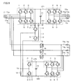
- FIG. 8 is a circuit block diagram showing a configuration of an uninterruptible power supply apparatus that is another modification of the second embodiment, and is a diagram that is compared with FIG. Referring to FIG. 8, this uninterruptible power supply differs from the uninterruptible power supply of FIG. 5 in that an insulating transformer 23 is added.
- the three primary terminals of the insulation transformer 23 are connected to the other terminals of the high-speed switches 4a to 4c, respectively, and are connected to the AC output terminals T4a to T4c via three switches (not shown).
- Three secondary terminals of the isolation transformer 23 are connected to three AC nodes (emitters of three transistors P) of the bidirectional power converter 5, respectively.
- the insulation transformer 23 normally transmits the three-phase AC power supplied from the commercial AC power supply 11 via the high-speed switches 4a to 4c to the bidirectional power converter 5, and at the time of a power failure, the bidirectional power converter 5 Is transmitted to the loads 14a to 14c. Even in this modified example, the same effect as in the second embodiment can be obtained.
- AC power consumed by the loads 13a to 13c passes through the insulating transformer 20 during normal times, and loss occurs in the insulating transformer 20.
- AC power consumed by the loads 14a to 14c passes through the insulation transformers 21 and 22, and loss occurs in the insulation transformers 21 and 22.
- AC power necessary for charging the battery 12 passes through the insulation transformer 23 in a normal state, and loss occurs in the insulation transformer 23. Since the AC power passing through the insulating transformer 23 among the insulating transformers 20 to 23 is the smallest, the loss generated in the insulating transformer 23 among the insulating transformers 20 to 23 is the smallest.
- the circulating current is interrupted by providing an insulating transformer in the path through which the alternating current flows in the circulating circuit.
- a diode ( The circulating current is cut off by providing a rectifying element.
- the uninterruptible power supply according to Embodiment 1 includes two bidirectional choppers 3 and 6, normally, the battery 12 is charged by one of the bidirectional choppers 3 and 6. In the event of a power failure, the battery 12 may be discharged by the bidirectional choppers 3 and 6. Therefore, the charging current of the battery 12 may be cut off and the diode may be connected to the current path of one of the bidirectional choppers 3 and 6 in the direction in which the discharging current flows.
- FIG. 9 is a circuit diagram showing the configuration of the uninterruptible power supply according to Embodiment 3 of the present invention, and is a diagram contrasted with FIG. Referring to FIG. 9, this uninterruptible power supply is different from the uninterruptible power supply of FIG. 5 in that diodes 31 and 32 are added.
- the anode of the diode 31 is connected to the collector of the transistor P of the bidirectional chopper 3, and the cathode is connected to the DC positive bus LP1.
- the anode of the diode 32 is connected to the DC negative bus LN 1, and the cathode thereof is connected to the emitter of the transistor Q of the bidirectional chopper 3.
- the diodes 31 and 32 allow current to flow from the battery 12 to the inverter 2 via the bidirectional chopper 3, and prohibit current from flowing from the converter 1 to the battery 12 via the bidirectional chopper 3.
- the same effect as in the second embodiment can be obtained. Furthermore, the diodes 31 and 32 are smaller than the insulating transformers 20 to 23, are inexpensive, and have low loss. Therefore, compared to the second embodiment, the device can be reduced in size, cost, and efficiency. it can.
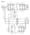
- FIG. 10 is a circuit block diagram showing a modification of the third embodiment, and is a diagram contrasted with FIG. Referring to FIG. 10, this uninterruptible power supply is different from the uninterruptible power supply of FIG. 9 in that the positions of diodes 31 and 32 are changed.
- the anode of the diode 31 is connected to the battery terminal T2, and the cathode thereof is connected to the emitter of the transistor P via the reactor (not shown) of the bidirectional chopper 3.
- the anode of the diode 32 is connected to the emitter of the transistor Q of the bidirectional chopper 3, and its cathode is connected to the negative electrode of the battery 12. Even in this modified example, the same effect as in the third embodiment can be obtained.
- the bi-directional chopper 3 of the two bi-directional choppers 3 and 6 is used as a discharge-dedicated chopper.
- both of the two bi-directional choppers 3 and 6 are used.
- the direction chopper 6 is used as a chopper exclusively for discharge.
- FIG. 11 is a circuit diagram showing the configuration of the uninterruptible power supply according to Embodiment 4 of the present invention, and is a diagram contrasted with FIG. Referring to FIG. 11, this uninterruptible power supply is different from the uninterruptible power supply of FIG. 5 in that diodes 33 and 34 are added.
- the anode of the diode 33 is connected to the collector of the transistor P of the bidirectional chopper 6, and its cathode is connected to the DC positive bus LP2.
- the anode of the diode 34 is connected to the DC negative bus LN 2, and the cathode thereof is connected to the emitter of the transistor Q of the bidirectional chopper 6.
- the diodes 33 and 34 allow current to flow from the battery 12 to the bidirectional power converter 5 via the bidirectional chopper 6, and current to the battery 12 from the bidirectional power converter 5 via the bidirectional chopper 6. Prohibit flowing.
- the same effect as in the second embodiment can be obtained. Furthermore, the diodes 33 and 34 are smaller than the insulating transformers 20 to 23, are inexpensive, and have low loss. Therefore, compared to the second embodiment, the device can be reduced in size, cost, and efficiency. it can.
- the diodes 33 and 34 having a smaller size than the diodes 31 and 32 of the third embodiment can be used.
- the diodes 33 and 34 having a size larger than the diodes 31 and 32 of the third embodiment it is necessary to use the diodes 33 and 34 having a size larger than the diodes 31 and 32 of the third embodiment.
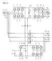
- FIG. 12 is a circuit block diagram illustrating a configuration of an uninterruptible power supply apparatus that is a modification of the fourth embodiment, and is a diagram contrasted with FIG. Referring to FIG. 12, this uninterruptible power supply is different from the uninterruptible power supply of FIG. 11 in that the positions of diodes 33 and 34 are changed.
- the anode of the diode 33 is connected to the battery terminal T2, and the cathode thereof is connected to the emitter of the transistor P via the reactor (not shown) of the bidirectional chopper 6.
- the anode of the diode 34 is connected to the emitter of the transistor Q of the bidirectional chopper 3, and the cathode thereof is connected to the negative electrode of the battery 12. Even in this modified example, the same effect as in the fourth embodiment can be obtained.
- FIG. 13 is a circuit diagram showing a configuration of an uninterruptible power supply according to Embodiment 5 of the present invention, and is compared with FIG. Referring to FIG. 13, this uninterruptible power supply differs from the uninterruptible power supply of FIG. 1 in that bidirectional chopper 3 is removed, and DC bus L1 between converter 1 and inverter 2 and bidirectional power converter 5 The DC bus L2 between the bidirectional choppers 6 is connected to each other.
- Converter 1 and inverter 2 constitute a first uninterruptible power supply unit of a constant inverter feeding system.
- the high-speed switch 4, the bidirectional power converter 5, and the bidirectional chopper 6 constitute a second uninterruptible power supply unit that is always in a commercial power supply system.
- the bidirectional chopper 6 is shared by the first and second uninterruptible power supply units.
- the operation of the converter 1 is stopped and the high-speed switch 4 is turned off, and the DC power of the battery 12 is converted by the bidirectional chopper 6 It is supplied to the bidirectional power converter 5.
- the inverter 2 converts DC power supplied from the battery 12 through the bidirectional chopper 6 into AC power and supplies the AC power to the load 13.
- the bidirectional power converter 5 converts DC power supplied from the battery 12 via the bidirectional chopper 6 into AC power and supplies the AC power to the load 14. Since other configurations and operations are the same as those in the first embodiment, description thereof will not be repeated.
- the same effect as in the first embodiment can be obtained, and the bidirectional chopper 3 is deleted, so that the apparatus can be reduced in size, priced, and simplified in configuration.
- FIG. 14 is a circuit block diagram for explaining the problem of the uninterruptible power supply shown in FIG. 13 and is a diagram contrasted with FIG. Referring to FIG. 14, in this uninterruptible power supply, bidirectional chopper 3 is removed, DC positive buses LP1 and LP2 are connected to each other, and DC negative buses LN1 and LN2 are connected to each other.
- the total of the three-phase AC current flowing from the commercial AC power supply 11 to the converter 1 is 0 A
- the total of the three-phase AC current flowing from the commercial AC power supply 11 to the bidirectional power converter 5 via the high-speed switches 4a to 4c is 0A
- the sum of the current flowing from the bidirectional chopper 6 to the positive electrode of the battery 12 and the current flowing from the bidirectional chopper 6 to the negative electrode of the battery 12 is 0A.
- the sum of these currents does not become 0 A, and it becomes difficult to accurately control the current flowing through the converter 1, the bidirectional power converter 5, and the bidirectional chopper 6.
- This problem can be solved by a method similar to the method shown in FIGS. That is, there are a method in which the insulating transformers 20 to 23 are arranged in a path through which an alternating current flows in the circulation circuit, and a method in which a diode is arranged in a path through which a direct current flows.
- the method of arranging the insulating transformers 20 to 23 is as shown in FIGS.
- the method of disposing the diode is slightly different from the method shown in FIGS.
- FIG. 15 is a circuit diagram showing a configuration of an uninterruptible power supply according to Embodiment 6 of the present invention, and is a diagram contrasted with FIG. Referring to FIG. 15, this uninterruptible power supply is different from the uninterruptible power supply of FIG. 14 in that diodes 41 and 42 are added.
- Diode 41 has an anode connected to DC positive bus LP2 and a cathode connected to DC positive bus LP1.
- Diode 42 has an anode connected to DC negative bus LN1, and a cathode connected to DC negative bus LN2.
- Diodes 41 and 42 allow current to flow from battery 12 to inverter 2 via bidirectional chopper 6, and prohibit current from flowing from converter 1 to battery 12 via bidirectional chopper 6.
- the three-phase AC power from the commercial AC power supply 11 is converted into DC power by the converter 1, and the DC power is converted into three-phase AC power by the inverter 2. It is converted and supplied to the loads 13a to 13c. Further, the high-speed switches 4a to 4c are turned on, and the three-phase AC power from the commercial AC power supply 11 is supplied to the loads 14a to 14c, and is converted into DC power by the bidirectional power converter 5, and the DC power is both It is stored in the battery 12 by the direction chopper 6. At this time, the circulating current indicated by the arrow in FIG.
- the operation of the converter 1 is stopped and the high-speed switches 4a to 4c are turned off.
- the DC power of the battery 12 is supplied to the inverter 2 through the bidirectional chopper 6 and the diodes 41 and 42, converted into three-phase AC power by the inverter 2, and supplied to the loads 13a to 13c. Further, the DC power of the battery 12 is supplied to the bidirectional power converter 5 by the bidirectional chopper 6, converted into three-phase AC power by the bidirectional power converter 5, and supplied to the loads 14a to 14c. At this time, since the operation of the converter 1 is stopped and the high speed switches 4a to 4c are turned off, a circulation circuit is not formed.
- the same effect as in the fifth embodiment can be obtained, and a circulating current can be prevented from flowing, and the converter 1, the inverter 2, the bidirectional power converter 5, and the bidirectional chopper 6 are provided.
- the flowing current can be accurately controlled.
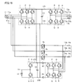
- FIG. 16 is a circuit diagram showing a configuration of the uninterruptible power supply according to Embodiment 7 of the present invention, and is compared with FIG. Referring to FIG. 16, this uninterruptible power supply is different from the uninterruptible power supply of FIG. 14 in that diodes 43 and 44 are added.
- the anode of the diode 43 is connected to the DC positive buses LP1 and LP2, and the cathode is connected to the collector of the transistor P of the bidirectional power converter 5.
- the anode of diode 44 is connected to the emitter of transistor Q of bidirectional power converter 5, and the cathode is connected to DC negative buses LN1, LN2.
- the diodes 43 and 44 allow current to flow from the battery 12 to the bidirectional power converter 5 through the bidirectional chopper 6, and current from the bidirectional power converter 5 to the battery 12 through the bidirectional chopper 6. Prohibit flowing.
- the three-phase AC power from the commercial AC power supply 11 is converted into DC power by the converter 1, and the DC power is supplied to the battery 12 by the bidirectional chopper 6. In addition to being stored, it is converted into three-phase AC power by the inverter 2 and supplied to the loads 13a to 13c. Further, the high speed switches 4a to 4c are turned on, and the three-phase AC power from the commercial AC power supply 11 is supplied to the loads 14a to 14c via the high speed switches 4a to 4c.
- the bidirectional power converter 5 is not operated. At this time, the circulating current indicated by the arrow in FIG.
- the operation of the converter 1 is stopped and the high-speed switches 4a to 4c are turned off.
- the DC power of the battery 12 is supplied to the inverter 2 by the bidirectional chopper 6, converted into three-phase AC power, and supplied to the loads 13a to 13c. Further, the DC power of the battery 12 is supplied to the bidirectional power converter 5 via the bidirectional chopper 6 and the diodes 43 and 44, converted into three-phase AC power, and supplied to the loads 14a to 14c. At this time, since the operation of the converter 1 is stopped and the high speed switches 4a to 4c are turned off, a circulation circuit is not formed.
- the same effect as in the fifth embodiment can be obtained, and a circulating current can be prevented from flowing, and the converter 1, the inverter 2, the bidirectional power converter 5, and the bidirectional chopper 6 are provided.
- the flowing current can be accurately controlled.
- FIG. 17 is a circuit diagram showing a configuration of an uninterruptible power supply according to Embodiment 8 of the present invention, which is compared with FIG. Referring to FIG. 17, this uninterruptible power supply differs from the uninterruptible power supply of FIG. 13 in that converter 1 is removed and the input node of inverter 2 is connected to DC bus L2.
- the inverter 2 constitutes a first uninterruptible power supply unit of a constant inverter feeding method.
- the high-speed switch 4, the bidirectional power converter 5, and the bidirectional chopper 6 constitute a second uninterruptible power supply unit that is always in a commercial power supply system.
- the high-speed switch 4, the bidirectional power converter 5, and the bidirectional chopper 6 are shared by the first and second uninterruptible power supply units.
- the high-speed switch 4 is turned on, AC power from the commercial AC power supply 11 is supplied to the load 14 via the high-speed switch 4, and bidirectional power conversion is performed. It is converted into DC power by the device 5.
- the DC power generated by the bidirectional power converter 5 is stored in the battery 12 by the bidirectional chopper 6, converted into AC power by the inverter 2, and supplied to the load 13.
- the high speed switch 4 When the supply of AC power from the commercial AC power supply 11 is stopped, the high speed switch 4 is turned off, and the DC power of the battery 12 is supplied to the inverter 2 and the bidirectional power converter 5 by the bidirectional chopper 6.
- the inverter 2 converts DC power supplied from the battery 12 through the bidirectional chopper 6 into AC power and supplies the AC power to the load 13.
- the bidirectional power converter 5 converts DC power supplied from the battery 12 via the bidirectional chopper 6 into AC power and supplies the AC power to the load 14. Since other configurations and operations are the same as those in the first embodiment, description thereof will not be repeated.
- the same effect as in the fifth embodiment can be obtained, and the converter 1 is omitted, so that the apparatus can be reduced in size, reduced in price, and simplified in configuration. That is, in the uninterruptible power supply apparatus of FIG. 13, in order to operate the load 13 with the power consumption of 100 kVA and the load 14 with the power consumption of 100 kVA, the converter 1 with the rated power of 110 kVA and the inverter 2 with the rated power of 100 kVA.
- the bidirectional power converter 5 with a rated power of 110 kVA and the bidirectional chopper 6 with a rated power of 200 kVA are required.
- the converter 1 is deleted, so that the circulation circuit is not configured. Therefore, since an insulating transformer or diode for interrupting the circulating current is not necessary, the apparatus can be reduced in size, cost, and configuration can be simplified.
Landscapes
- Engineering & Computer Science (AREA)
- Power Engineering (AREA)
- Business, Economics & Management (AREA)
- Emergency Management (AREA)
- Stand-By Power Supply Arrangements (AREA)
- Inverter Devices (AREA)
Abstract
Description
図1は、この発明の実施の形態1による無停電電源装置の構成を示す回路ブロック図である。図1において、この無停電電源装置は、交流入力端子(第1の端子)T1、バッテリ端子(第2の端子)T2、交流出力端子(第3の端子)T3、交流出力端子(第4の端子)T4、スイッチS1~S6、コンバータ1、インバータ2、双方向チョッパ3,6、高速スイッチ4、および双方向電力変換器5を備える。
図4は、図1に示した無停電電源装置の問題点を説明するための回路ブロック図である。図4では、スイッチS1~S6の図示は省略されており、スイッチS1~S4がオンされ、スイッチS5,S6がオフされた場合が示されている。図1に示した無停電電源装置を運転すると、図4に示すように、コンバータ1、高速スイッチ4、双方向電力変換器5、双方向チョッパ6、および双方向チョッパ3によって循環回路が形成され、循環電流が流れる恐れがある。そのような循環電流が流れると、コンバータ1、双方向チョッパ3,6、および双方向電力変換器5に流れる電流を正確に制御することが困難になる。
実施の形態2では、循環回路のうちの交流電流が流れる経路に絶縁トランスを設けることによって循環電流を遮断したが、この実施の形態3では、循環回路のうちの直流電流が流れる経路にダイオード(整流素子)を設けることによって循環電流を遮断する。実施の形態1の無停電電源装置は2つの双方向チョッパ3,6を備えているが、通常時は、双方向チョッパ3,6のうちのいずれか一方の双方向チョッパによってバッテリ12を充電し、停電時は、双方向チョッパ3,6によってバッテリ12を放電させればよい。したがって、双方向チョッパ3,6のうちのいずれか一方の双方向チョッパの電流経路に、バッテリ12の充電電流を遮断し、放電電流を流す方向にダイオードを接続すればよい。
実施の形態3では、2つの双方向チョッパ3,6のうちの双方向チョッパ3を放電専用のチョッパとして使用したが、本実施の形態4では、2つの双方向チョッパ3,6のうちの双方向チョッパ6を放電専用のチョッパとして使用する。
図13は、この発明の実施の形態5による無停電電源装置の構成を示す回路図であって、図1と対比される図である。図13を参照して、この無停電電源装置が図1の無停電電源装置と異なる点は、双方向チョッパ3が除去され、コンバータ1およびインバータ2間の直流母線L1と双方向電力変換器5および双方向チョッパ6間の直流母線L2とが互いに接続されている点である。
図14は、図13に示した無停電電源装置の問題点を説明するための回路ブロック図であって図5と対比される図である。図14を参照して、この無停電電源装置では、双方向チョッパ3が除去され、直流正母線LP1,LP2が互いに接続され、直流負母線LN1,LN2が互いに接続される。
図16は、この発明の実施の形態7による無停電電源装置の構成を示す回路図であって、図14と対比される図である。図16を参照して、この無停電電源装置が図14の無停電電源装置と異なる点は、ダイオード43,44が追加されている点である。
図17は、この発明の実施の形態8による無停電電源装置の構成を示す回路図であって、図13と対比される図である。図17を参照して、この無停電電源装置が図13の無停電電源装置と異なる点は、コンバータ1が除去され、インバータ2の入力ノードが直流母線L2に接続されている点である。
Claims (19)
- 商用交流電源から交流電力を受ける第1の端子と、
電力貯蔵装置に接続される第2の端子と、
第1の負荷に接続される第3の端子と、
第2の負荷に接続される第4の端子と、
前記第1~第3の端子に接続された第1の無停電電源部と、
前記第1、第2、および第4の端子に接続された第2の無停電電源部とを備え、
前記第1の無停電電源部は、前記商用交流電源から交流電力が供給されている通常時は、前記商用交流電源からの交流電力を直流電力に変換し、その直流電力を前記電力貯蔵装置に蓄えるとともに交流電力に変換して前記第1の負荷に供給し、前記商用交流電源からの交流電力の供給が停止された停電時は、前記電力貯蔵装置の直流電力を交流電力に変換して前記負荷に供給し、
前記第2の無停電電源部は、前記通常時は、前記商用交流電源からの交流電力を前記第2の負荷に供給し、前記停電時は、前記電力貯蔵装置の直流電力を交流電力に変換して前記第2の負荷に供給する、無停電電源装置。 - 前記第1の無停電電源部は、
前記第1の端子に接続され、前記商用交流電源からの交流電力を直流電力に変換するコンバータと、
前記第3の端子に接続され、直流電力を交流電力に変換して前記第1の負荷に供給するインバータと、
前記第2の端子に接続され、前記通常時は、前記コンバータによって生成された直流電力を前記電力貯蔵装置に蓄え、前記停電時は、前記電力貯蔵装置の直流電力を前記インバータに供給する第1の双方向チョッパとを含み、
前記第2の無停電電源部は、
前記第1および第4の端子間に接続され、前記通常時はオンし、前記停電時はオフする高速スイッチと、
前記第4の端子に接続され、前記通常時は、前記商用交流電源から前記高速スイッチを介して供給される交流電力を直流電力に変換し、前記停電時は、直流電力を交流電力に変換して前記第2の負荷に供給する双方向電力変換器と、
前記第2の端子に接続され、前記通常時は、前記双方向電力変換器によって生成された直流電力を前記電力貯蔵装置に蓄え、前記停電時は、前記電力貯蔵装置の直流電力を前記双方向電力変換器に供給する第2の双方向チョッパとを含む、請求項1に記載の無停電電源装置。 - さらに、1次側端子が前記第1の端子および前記高速スイッチの一方端子に接続され、2次側端子が前記コンバータの入力ノードに接続され、前記商用交流電源からの交流電力を前記コンバータに伝達する絶縁トランスを備える、請求項2に記載の無停電電源装置。
- さらに、1次側端子が前記第1の端子および前記コンバータの入力ノードに接続され、2次側端子が前記高速スイッチの一方端子に接続され、前記商用交流電源からの交流電力を前記高速スイッチを介して前記第2の負荷および前記双方向電力変換器に伝達する絶縁トランスを備える、請求項2に記載の無停電電源装置。
- さらに、1次側端子が前記高速スイッチの一方端子に接続され、2次側端子が前記第4の端子および前記双方向電力変換器に接続され、前記商用交流電源から前記高速スイッチを介して供給される交流電力を前記第2の負荷および前記双方向電力変換器に伝達する絶縁トランスを備える、請求項2に記載の無停電電源装置。
- さらに、1次側端子が前記高速スイッチの一方端子および前記第4の端子に接続され、2次側端子が前記双方向電力変換器に接続され、前記商用交流電源から前記高速スイッチを介して供給される交流電力を前記双方向電力変換器に伝達する絶縁トランスを備える、請求項2に記載の無停電電源装置。
- さらに、前記電力貯蔵装置から前記第1の双方向チョッパを介して前記インバータに電流が流れることを許容し、前記コンバータから前記第1の双方向チョッパを介して前記電力貯蔵装置に電流が流れることを禁止する整流素子を備える、請求項2に記載の無停電電源装置。
- さらに、前記電力貯蔵装置から前記第2の双方向チョッパを介して前記双方向電力変換器に電流が流れることを許容し、前記双方向電力変換器から前記第2の双方向チョッパを介して前記電力貯蔵装置に電流が流れることを禁止する整流素子を備える、請求項2に記載の無停電電源装置。
- さらに、前記第1の端子と前記コンバータの入力ノードおよび前記高速スイッチの一方端子との間に接続された第1のスイッチと、
前記第2の端子と前記第1および第2の双方向チョッパとの間に接続された第2のスイッチと、
前記第3の端子と前記インバータの出力ノードとの間に接続された第3のスイッチと、
前記第4の端子と前記高速スイッチの他方端子および前記双方向電力変換器との間に接続された第4のスイッチと、
前記第1および第3の端子間に接続された第5のスイッチと、
前記第1および第4の端子間に接続された第6のスイッチとを備え、
前記無停電電源装置を運転する場合は前記第1~第4のスイッチがオンされるとともに前記第5および第6のスイッチがオフされ、
前記無停電電源装置のメンテナンス時は前記第1~第4のスイッチがオフされるとともに前記第5および第6のスイッチがオンされる、請求項2に記載の無停電電源装置。 - 前記第1の無停電電源部は、
前記第1の端子に接続され、前記商用交流電源からの交流電力を直流電力に変換するコンバータと、
前記第3の端子に接続され、直流電力を交流電力に変換して前記第1の負荷に供給するインバータとを含み、
前記第2の無停電電源部は、
前記第1および第4の端子間に接続され、前記通常時はオンし、前記停電時はオフする高速スイッチと、
前記第4の端子に接続され、前記通常時は、前記商用交流電源から前記高速スイッチを介して供給される交流電力を直流電力に変換し、前記停電時は、直流電力を交流電力に変換して前記第2の負荷に供給する双方向電力変換器と、
前記第2の端子に接続され、前記通常時は、前記コンバータおよび前記双方向電力変換器によって生成された直流電力を前記電力貯蔵装置に蓄え、前記停電時は、前記電力貯蔵装置の直流電力を前記インバータおよび前記双方向電力変換器に供給する双方向チョッパとを含み、
前記双方向チョッパは、前記第1および第2の無停電電源部によって共用される、請求項1に記載の無停電電源装置。 - さらに、1次側端子が前記第1の端子および前記高速スイッチの一方端子に接続され、2次側端子が前記コンバータの入力ノードに接続され、前記商用交流電源からの交流電力を前記コンバータに伝達する絶縁トランスを備える、請求項10に記載の無停電電源装置。
- さらに、1次側端子が前記第1の端子および前記コンバータの入力ノードに接続され、2次側端子が前記高速スイッチの一方端子に接続され、前記商用交流電源からの交流電力を前記高速スイッチを介して前記第2の負荷および前記双方向電力変換器に伝達する絶縁トランスを備える、請求項10に記載の無停電電源装置。
- さらに、1次側端子が前記高速スイッチの一方端子に接続され、2次側端子が前記第4の端子および前記双方向電力変換器に接続され、前記商用交流電源から前記高速スイッチを介して供給される交流電力を前記第2の負荷および前記双方向電力変換器に伝達する絶縁トランスを備える、請求項10に記載の無停電電源装置。
- さらに、1次側端子が前記高速スイッチの一方端子および前記第4の端子に接続され、2次側端子が前記双方向電力変換器に接続され、前記商用交流電源から前記高速スイッチを介して供給される交流電力を前記双方向電力変換器に伝達する絶縁トランスを備える、請求項10に記載の無停電電源装置。
- さらに、前記電力貯蔵装置から前記双方向チョッパを介して前記インバータに電流が流れることを許容し、前記コンバータから前記双方向チョッパを介して前記電力貯蔵装置に電流が流れることを禁止する整流素子を備える、請求項10に記載の無停電電源装置。
- さらに、前記電力貯蔵装置から前記双方向チョッパを介して前記双方向電力変換器に電流が流れることを許容し、前記双方向電力変換器から前記双方向チョッパを介して前記電力貯蔵装置に電流が流れることを禁止する整流素子を備える、請求項10に記載の無停電電源装置。
- さらに、前記第1の端子と前記コンバータの入力ノードおよび前記高速スイッチの一方端子との間に接続された第1のスイッチと、
前記第2の端子と前記双方向チョッパとの間に接続された第2のスイッチと、
前記第3の端子と前記インバータの出力ノードとの間に接続された第3のスイッチと、
前記第4の端子と前記高速スイッチの他方端子および前記双方向電力変換器との間に接続された第4のスイッチと、
前記第1および第3の端子間に接続された第5のスイッチと、
前記第1および第4の端子間に接続された第6のスイッチとを備え、
前記無停電電源装置を運転する場合は前記第1~第4のスイッチがオンされるとともに前記第5および第6のスイッチがオフされ、
前記無停電電源装置のメンテナンス時は前記第1~第4のスイッチがオフされるとともに前記第5および第6のスイッチがオンされる、請求項10に記載の無停電電源装置。 - 前記第1の無停電電源部は、前記第3の端子に接続され、直流電力を交流電力に変換して前記第1の負荷に供給するインバータを含み、
前記第2の無停電電源部は、
前記第1および第4の端子間に接続され、前記通常時はオンし、前記停電時はオフする高速スイッチと、
前記第4の端子に接続され、前記通常時は、前記商用交流電源から前記高速スイッチを介して供給される交流電力を直流電力に変換し、前記停電時は、直流電力を交流電力に変換して前記第2の負荷に供給する双方向電力変換器と、
前記第2の端子に接続され、前記通常時は、前記双方向電力変換器によって生成された直流電力を前記電力貯蔵装置に蓄え、前記停電時は、前記電力貯蔵装置の直流電力を前記インバータおよび前記双方向電力変換器に供給する双方向チョッパとを含み、
前記高速スイッチ、前記双方向電力変換器、および前記双方向チョッパは、前記第1および第2の無停電電源部によって共用される、請求項1に記載の無停電電源装置。 - さらに、前記第1の端子と前記高速スイッチの一方端子との間に接続された第1のスイッチと、
前記第2の端子と前記双方向チョッパとの間に接続された第2のスイッチと、
前記第3の端子と前記インバータの出力ノードとの間に接続された第3のスイッチと、
前記第4の端子と前記高速スイッチの他方端子および前記双方向電力変換器との間に接続された第4のスイッチと、
前記第1および第3の端子間に接続された第5のスイッチと、
前記第1および第4の端子間に接続された第6のスイッチとを備え、
前記無停電電源装置を運転する場合は前記第1~第4のスイッチがオンされるとともに前記第5および第6のスイッチがオフされ、
前記無停電電源装置のメンテナンス時は前記第1~第4のスイッチがオフされるとともに前記第5および第6のスイッチがオンされる、請求項18に記載の無停電電源装置。
Priority Applications (4)
| Application Number | Priority Date | Filing Date | Title |
|---|---|---|---|
| PCT/JP2015/067696 WO2016203635A1 (ja) | 2015-06-19 | 2015-06-19 | 無停電電源装置 |
| JP2017524254A JP6412266B2 (ja) | 2015-06-19 | 2015-06-19 | 無停電電源装置 |
| US15/736,610 US10554076B2 (en) | 2015-06-19 | 2015-06-19 | Uninterruptible power supply |
| KR1020187000718A KR101989758B1 (ko) | 2015-06-19 | 2015-06-19 | 무정전 전원 장치 |
Applications Claiming Priority (1)
| Application Number | Priority Date | Filing Date | Title |
|---|---|---|---|
| PCT/JP2015/067696 WO2016203635A1 (ja) | 2015-06-19 | 2015-06-19 | 無停電電源装置 |
Publications (2)
| Publication Number | Publication Date |
|---|---|
| WO2016203635A1 true WO2016203635A1 (ja) | 2016-12-22 |
| WO2016203635A9 WO2016203635A9 (ja) | 2017-09-28 |
Family
ID=57545696
Family Applications (1)
| Application Number | Title | Priority Date | Filing Date |
|---|---|---|---|
| PCT/JP2015/067696 Ceased WO2016203635A1 (ja) | 2015-06-19 | 2015-06-19 | 無停電電源装置 |
Country Status (4)
| Country | Link |
|---|---|
| US (1) | US10554076B2 (ja) |
| JP (1) | JP6412266B2 (ja) |
| KR (1) | KR101989758B1 (ja) |
| WO (1) | WO2016203635A1 (ja) |
Cited By (3)
| Publication number | Priority date | Publication date | Assignee | Title |
|---|---|---|---|---|
| JP6533357B1 (ja) * | 2018-11-22 | 2019-06-19 | 東芝三菱電機産業システム株式会社 | 無停電電源装置 |
| JP2021505115A (ja) * | 2017-11-28 | 2021-02-15 | エルエス、エレクトリック、カンパニー、リミテッドLs Electric Co., Ltd. | エネルギー貯蔵システム |
| WO2025239040A1 (ja) * | 2024-05-15 | 2025-11-20 | パナソニックIpマネジメント株式会社 | 電源システムおよび制御方法 |
Families Citing this family (12)
| Publication number | Priority date | Publication date | Assignee | Title |
|---|---|---|---|---|
| CN105991080B (zh) * | 2015-02-26 | 2021-09-10 | 伊顿智能动力有限公司 | 一种用于电机和供电网的连接装置 |
| JP6191745B1 (ja) * | 2016-08-10 | 2017-09-06 | 富士電機株式会社 | 無停電電源装置 |
| EP3291411B1 (de) * | 2016-09-01 | 2019-05-08 | Maschinenfabrik Reinhausen GmbH | Verfahren zum steuern einer unterbrechungsfreien stromversorgung und anlage für eine unterbrechungsfreie stromversorgung |
| CN108988479B (zh) * | 2018-08-17 | 2022-08-19 | 华为数字能源技术有限公司 | 一种数据中心及其控制方法 |
| CN113169660B (zh) * | 2019-07-04 | 2024-03-08 | 东芝三菱电机产业系统株式会社 | 同步控制电路及具备同步控制电路的不间断电源装置 |
| US11345253B2 (en) | 2019-09-19 | 2022-05-31 | Nio Usa, Inc. | Vehicle power devices, systems, and methods for fail operational electronic control unit power management |
| KR102448969B1 (ko) * | 2020-06-26 | 2022-09-29 | 한화시스템 주식회사 | 전원 제어 장치 및 이를 구비하는 항전 장비 |
| KR102448970B1 (ko) * | 2020-06-26 | 2022-09-29 | 한화시스템 주식회사 | 전원 제어 장치 및 이를 구비하는 항전 장비 |
| CN112018867B (zh) * | 2020-07-27 | 2022-05-10 | 科华恒盛股份有限公司 | 可配置共用电池的不间断电源及不间断电源并机系统 |
| DK180966B1 (en) | 2020-09-18 | 2022-08-18 | Kk Wind Solutions As | Multiple output energy storage |
| CN114189034B (zh) * | 2021-12-29 | 2024-07-23 | 常熟开关制造有限公司(原常熟开关厂) | 一种混合式双电源转换装置 |
| CN116667494B (zh) * | 2023-06-07 | 2024-10-18 | 深圳市正浩创新科技股份有限公司 | 供电电路及储能设备 |
Citations (4)
| Publication number | Priority date | Publication date | Assignee | Title |
|---|---|---|---|---|
| JPH06113489A (ja) * | 1992-09-29 | 1994-04-22 | Fuji Electric Co Ltd | 無停電電源装置の保守用バイパス回路 |
| JPH11215738A (ja) * | 1998-01-26 | 1999-08-06 | Hitachi Ltd | 無停電電源装置 |
| US20050201127A1 (en) * | 2004-03-09 | 2005-09-15 | Tracy John G. | Multi-mode uninterruptible power supplies and methods of operation thereof |
| WO2015006151A1 (en) * | 2013-07-08 | 2015-01-15 | Eaton Corporation | Ups systems and methods using variable configuration modules |
Family Cites Families (3)
| Publication number | Priority date | Publication date | Assignee | Title |
|---|---|---|---|---|
| KR100509263B1 (ko) * | 2004-04-21 | 2005-08-22 | 주식회사 크로마아이티 | 온/오프라인 복합형의 고효율 무정전전원장치 |
| JP2011223731A (ja) | 2010-04-09 | 2011-11-04 | Meidensha Corp | 無停電電源システム、および無停電電源システムの制御方法 |
| US20150000874A1 (en) * | 2013-06-28 | 2015-01-01 | Hamilton Sundstrand Corporation | Fuel oil heat exchanger utilizing heat pipes |
-
2015
- 2015-06-19 US US15/736,610 patent/US10554076B2/en active Active
- 2015-06-19 WO PCT/JP2015/067696 patent/WO2016203635A1/ja not_active Ceased
- 2015-06-19 KR KR1020187000718A patent/KR101989758B1/ko active Active
- 2015-06-19 JP JP2017524254A patent/JP6412266B2/ja active Active
Patent Citations (4)
| Publication number | Priority date | Publication date | Assignee | Title |
|---|---|---|---|---|
| JPH06113489A (ja) * | 1992-09-29 | 1994-04-22 | Fuji Electric Co Ltd | 無停電電源装置の保守用バイパス回路 |
| JPH11215738A (ja) * | 1998-01-26 | 1999-08-06 | Hitachi Ltd | 無停電電源装置 |
| US20050201127A1 (en) * | 2004-03-09 | 2005-09-15 | Tracy John G. | Multi-mode uninterruptible power supplies and methods of operation thereof |
| WO2015006151A1 (en) * | 2013-07-08 | 2015-01-15 | Eaton Corporation | Ups systems and methods using variable configuration modules |
Cited By (5)
| Publication number | Priority date | Publication date | Assignee | Title |
|---|---|---|---|---|
| JP2021505115A (ja) * | 2017-11-28 | 2021-02-15 | エルエス、エレクトリック、カンパニー、リミテッドLs Electric Co., Ltd. | エネルギー貯蔵システム |
| US11205911B2 (en) | 2017-11-28 | 2021-12-21 | Ls Electric Co., Ltd. | Energy storage system |
| JP6533357B1 (ja) * | 2018-11-22 | 2019-06-19 | 東芝三菱電機産業システム株式会社 | 無停電電源装置 |
| WO2020105172A1 (ja) * | 2018-11-22 | 2020-05-28 | 東芝三菱電機産業システム株式会社 | 無停電電源装置 |
| WO2025239040A1 (ja) * | 2024-05-15 | 2025-11-20 | パナソニックIpマネジメント株式会社 | 電源システムおよび制御方法 |
Also Published As
| Publication number | Publication date |
|---|---|
| WO2016203635A9 (ja) | 2017-09-28 |
| JPWO2016203635A1 (ja) | 2018-02-08 |
| US10554076B2 (en) | 2020-02-04 |
| KR101989758B1 (ko) | 2019-06-14 |
| JP6412266B2 (ja) | 2018-10-24 |
| KR20180016551A (ko) | 2018-02-14 |
| US20180191194A1 (en) | 2018-07-05 |
Similar Documents
| Publication | Publication Date | Title |
|---|---|---|
| JP6412266B2 (ja) | 無停電電源装置 | |
| US20200059111A1 (en) | Direct current power supply system | |
| KR102129177B1 (ko) | Spdt를 이용한 직류배전단 교차 전력 공급 시스템을 갖는 선박 | |
| CN104701969A (zh) | 不间断电源和不间断电源系统 | |
| KR20200019986A (ko) | 무정전 전원 시스템 | |
| TWI899442B (zh) | 包含雙模式微電網變流器的微電網及負載管理之方法 | |
| US20170354067A1 (en) | Power system and method | |
| US20170093157A1 (en) | Energy storage system with dual-active-bridge converter | |
| JP2015070746A (ja) | 制御装置および蓄電システム | |
| US20220352748A1 (en) | Systems and methods for supplying uninterruptible power | |
| KR20170026695A (ko) | 하이브리드 에너지저장 시스템 | |
| JP2016021801A (ja) | 無停電電源装置 | |
| AU2018401837B2 (en) | System for powering auxiliary loads of an energy storage system | |
| JP7242238B2 (ja) | 電力変換装置及び分散型電源システム | |
| EP4033624A1 (en) | Power distribution system and server system | |
| CN113196612A (zh) | 具有不间断电力供应的微电网系统 | |
| CN113746194A (zh) | 一种双柔直单元分送输电系统及其电气连接方法 | |
| US20130044529A1 (en) | Power Supply Control System | |
| JP7470750B2 (ja) | 電源システム | |
| CN214429313U (zh) | 一种电源切换电路 | |
| CN117856431B (zh) | 一种分布式电源控制系统的冗余供电装置及供电方法 | |
| US12003098B2 (en) | Systems and methods for a modular scalable architecture for energy storage auxiliary power and functions | |
| TW202543197A (zh) | 中低電壓電力中心 | |
| JP2024163788A (ja) | 駆動システム | |
| KR102010606B1 (ko) | 전력변환 시스템 |
Legal Events
| Date | Code | Title | Description |
|---|---|---|---|
| 121 | Ep: the epo has been informed by wipo that ep was designated in this application |
Ref document number: 15895655 Country of ref document: EP Kind code of ref document: A1 |
|
| ENP | Entry into the national phase |
Ref document number: 2017524254 Country of ref document: JP Kind code of ref document: A |
|
| NENP | Non-entry into the national phase |
Ref country code: DE |
|
| ENP | Entry into the national phase |
Ref document number: 20187000718 Country of ref document: KR Kind code of ref document: A |
|
| 122 | Ep: pct application non-entry in european phase |
Ref document number: 15895655 Country of ref document: EP Kind code of ref document: A1 |