WO2016200100A1 - 적응적 가중치 예측을 위한 신택스 시그널링을 이용하여 영상을 부호화 또는 복호화하는 방법 및 장치 - Google Patents
적응적 가중치 예측을 위한 신택스 시그널링을 이용하여 영상을 부호화 또는 복호화하는 방법 및 장치 Download PDFInfo
- Publication number
- WO2016200100A1 WO2016200100A1 PCT/KR2016/005908 KR2016005908W WO2016200100A1 WO 2016200100 A1 WO2016200100 A1 WO 2016200100A1 KR 2016005908 W KR2016005908 W KR 2016005908W WO 2016200100 A1 WO2016200100 A1 WO 2016200100A1
- Authority
- WO
- WIPO (PCT)
- Prior art keywords
- prediction
- unit
- information
- syntax elements
- coding unit
- Prior art date
Links
Images


Classifications
-
- H—ELECTRICITY
- H04—ELECTRIC COMMUNICATION TECHNIQUE
- H04N—PICTORIAL COMMUNICATION, e.g. TELEVISION
- H04N19/00—Methods or arrangements for coding, decoding, compressing or decompressing digital video signals
- H04N19/70—Methods or arrangements for coding, decoding, compressing or decompressing digital video signals characterised by syntax aspects related to video coding, e.g. related to compression standards
-
- H—ELECTRICITY
- H04—ELECTRIC COMMUNICATION TECHNIQUE
- H04N—PICTORIAL COMMUNICATION, e.g. TELEVISION
- H04N19/00—Methods or arrangements for coding, decoding, compressing or decompressing digital video signals
- H04N19/10—Methods or arrangements for coding, decoding, compressing or decompressing digital video signals using adaptive coding
- H04N19/102—Methods or arrangements for coding, decoding, compressing or decompressing digital video signals using adaptive coding characterised by the element, parameter or selection affected or controlled by the adaptive coding
- H04N19/103—Selection of coding mode or of prediction mode
- H04N19/109—Selection of coding mode or of prediction mode among a plurality of temporal predictive coding modes
-
- H—ELECTRICITY
- H04—ELECTRIC COMMUNICATION TECHNIQUE
- H04N—PICTORIAL COMMUNICATION, e.g. TELEVISION
- H04N19/00—Methods or arrangements for coding, decoding, compressing or decompressing digital video signals
- H04N19/10—Methods or arrangements for coding, decoding, compressing or decompressing digital video signals using adaptive coding
- H04N19/134—Methods or arrangements for coding, decoding, compressing or decompressing digital video signals using adaptive coding characterised by the element, parameter or criterion affecting or controlling the adaptive coding
- H04N19/157—Assigned coding mode, i.e. the coding mode being predefined or preselected to be further used for selection of another element or parameter
- H04N19/159—Prediction type, e.g. intra-frame, inter-frame or bidirectional frame prediction
-
- H—ELECTRICITY
- H04—ELECTRIC COMMUNICATION TECHNIQUE
- H04N—PICTORIAL COMMUNICATION, e.g. TELEVISION
- H04N19/00—Methods or arrangements for coding, decoding, compressing or decompressing digital video signals
- H04N19/10—Methods or arrangements for coding, decoding, compressing or decompressing digital video signals using adaptive coding
- H04N19/169—Methods or arrangements for coding, decoding, compressing or decompressing digital video signals using adaptive coding characterised by the coding unit, i.e. the structural portion or semantic portion of the video signal being the object or the subject of the adaptive coding
- H04N19/17—Methods or arrangements for coding, decoding, compressing or decompressing digital video signals using adaptive coding characterised by the coding unit, i.e. the structural portion or semantic portion of the video signal being the object or the subject of the adaptive coding the unit being an image region, e.g. an object
- H04N19/176—Methods or arrangements for coding, decoding, compressing or decompressing digital video signals using adaptive coding characterised by the coding unit, i.e. the structural portion or semantic portion of the video signal being the object or the subject of the adaptive coding the unit being an image region, e.g. an object the region being a block, e.g. a macroblock
-
- H—ELECTRICITY
- H04—ELECTRIC COMMUNICATION TECHNIQUE
- H04N—PICTORIAL COMMUNICATION, e.g. TELEVISION
- H04N19/00—Methods or arrangements for coding, decoding, compressing or decompressing digital video signals
- H04N19/44—Decoders specially adapted therefor, e.g. video decoders which are asymmetric with respect to the encoder
-
- H—ELECTRICITY
- H04—ELECTRIC COMMUNICATION TECHNIQUE
- H04N—PICTORIAL COMMUNICATION, e.g. TELEVISION
- H04N19/00—Methods or arrangements for coding, decoding, compressing or decompressing digital video signals
- H04N19/50—Methods or arrangements for coding, decoding, compressing or decompressing digital video signals using predictive coding
- H04N19/503—Methods or arrangements for coding, decoding, compressing or decompressing digital video signals using predictive coding involving temporal prediction
- H04N19/51—Motion estimation or motion compensation
- H04N19/513—Processing of motion vectors
- H04N19/517—Processing of motion vectors by encoding
- H04N19/52—Processing of motion vectors by encoding by predictive encoding
-
- H—ELECTRICITY
- H04—ELECTRIC COMMUNICATION TECHNIQUE
- H04N—PICTORIAL COMMUNICATION, e.g. TELEVISION
- H04N19/00—Methods or arrangements for coding, decoding, compressing or decompressing digital video signals
- H04N19/50—Methods or arrangements for coding, decoding, compressing or decompressing digital video signals using predictive coding
- H04N19/503—Methods or arrangements for coding, decoding, compressing or decompressing digital video signals using predictive coding involving temporal prediction
- H04N19/51—Motion estimation or motion compensation
- H04N19/577—Motion compensation with bidirectional frame interpolation, i.e. using B-pictures
-
- H—ELECTRICITY
- H04—ELECTRIC COMMUNICATION TECHNIQUE
- H04N—PICTORIAL COMMUNICATION, e.g. TELEVISION
- H04N19/00—Methods or arrangements for coding, decoding, compressing or decompressing digital video signals
- H04N19/10—Methods or arrangements for coding, decoding, compressing or decompressing digital video signals using adaptive coding
- H04N19/134—Methods or arrangements for coding, decoding, compressing or decompressing digital video signals using adaptive coding characterised by the element, parameter or criterion affecting or controlling the adaptive coding
- H04N19/136—Incoming video signal characteristics or properties
- H04N19/137—Motion inside a coding unit, e.g. average field, frame or block difference
- H04N19/139—Analysis of motion vectors, e.g. their magnitude, direction, variance or reliability
-
- H—ELECTRICITY
- H04—ELECTRIC COMMUNICATION TECHNIQUE
- H04N—PICTORIAL COMMUNICATION, e.g. TELEVISION
- H04N19/00—Methods or arrangements for coding, decoding, compressing or decompressing digital video signals
- H04N19/10—Methods or arrangements for coding, decoding, compressing or decompressing digital video signals using adaptive coding
- H04N19/169—Methods or arrangements for coding, decoding, compressing or decompressing digital video signals using adaptive coding characterised by the coding unit, i.e. the structural portion or semantic portion of the video signal being the object or the subject of the adaptive coding
- H04N19/182—Methods or arrangements for coding, decoding, compressing or decompressing digital video signals using adaptive coding characterised by the coding unit, i.e. the structural portion or semantic portion of the video signal being the object or the subject of the adaptive coding the unit being a pixel
Definitions
- the present invention relates to a method for encoding and decoding an image, and more particularly, to an image encoding and decoding method and apparatus using one or more prefix and additional syntax elements added to a bitstream to perform weighted bidirectional prediction.
- High-efficiency image compression technology can be used to effectively transmit, store, and reproduce high-resolution, high-quality video information.
- a method of predicting using information of neighboring blocks of the current block may be used without transmitting information of the current block as it is.
- inter prediction and intra prediction can be used.
- the pixel value of the current picture is predicted by referring to information of another picture, and in the intra prediction method, the pixel value is determined by using the correlation between pixels in the same picture. Predict.
- information indicating a reference picture and information indicating a motion vector from neighboring blocks in the inter prediction mode may be used to designate a portion used for prediction in another picture.
- the encoding apparatus entropy encodes the image information including the prediction result and transmits the image information into the bitstream, and the decoding apparatus entropy decodes the received bitstream to restore the image information.
- Entropy encoding and entropy decoding can improve the compression efficiency of image information.
- the technical problem to be solved by the present invention is to improve the accuracy of inter-decoding by improving the accuracy of inter-screen prediction by using syntax signaling for adaptive weight prediction.
- an image decoding method may include at least one prefix including a first counter value indicating a number of additional syntax elements subsequent to main syntax elements from a received bitstream ( obtaining a prefix); Based on the one or more prefixes, acquiring the additional syntax elements including information on whether to perform weighted bi-prediction of divided prediction units for prediction of a current block and weight information; And generating a prediction block that includes a prediction value based on the main syntax elements and the additional syntax elements.
- each of the additional syntax elements may be configured with information about whether the weighted bidirectional prediction is performed and a set of two bins for indicating the weighted information. .
- the one or more prefix may include a second counter value indicating the number of additional syntax elements including information indicating that the weighted bidirectional prediction is performed among the additional syntax elements. have.
- the acquiring the additional syntax elements may include determining probability information of bins of the additional syntax elements based on the first counter value and the second counter value; And sequentially decoding the bins of the additional syntax elements based on the probability information.
- the determining of the probability information may include: decreasing the second counter value by sequentially decoding the bins of the additional syntax elements; And updating the probability information by using the first counter value and the reduced second counter value.
- the generating of the prediction block may include generating a first reference picture most similar to the current block from a first motion vector and a second motion vector included in the main syntax elements. Determining a second corresponding region of the first corresponding region and the second reference picture; Determining whether to perform the weighted bidirectional prediction based on the first corresponding region and the second corresponding region; And performing weighted bidirectional motion compensation on a block basis or a pixel basis for the current block by using the first motion vector, the second motion vector, and the weight information.
- the determining of whether to perform the weighted bidirectional prediction in the image decoding method may include: referring to a first corresponding pixel and the second reference pixel of the first reference picture corresponding to each pixel of the current block; Determining not to perform the weighted bidirectional prediction if the difference value of the second corresponding pixel of the picture is less than a predetermined threshold value, and to perform the weighted bidirectional prediction if the difference value is not less than the predetermined threshold value; can do.
- an apparatus for decoding an image may include at least one prefix including a first counter value indicating a number of additional syntax elements following main syntax elements from a received bitstream.
- the additional syntax including information on whether to perform a weighted bi-prediction of divided prediction units for prediction of a current block based on the at least one prefix, and obtaining weight;
- a decoder configured to generate a prediction block including a prediction value based on the main syntax elements and the additional syntax elements.
- each of the additional syntax elements may be configured with information about whether to perform the weighted bidirectional prediction and two sets of bins for indicating the weight information. .
- the one or more prefixes may include a second counter value indicating the number of additional syntax elements including information indicating that the weighted bidirectional prediction is performed among the additional syntax elements. have.
- the additional syntax elements determine probability information of bins of the additional syntax elements based on the first counter value and the second counter value and based on the probability information. Can be obtained by sequentially decoding the bins of the additional syntax elements.
- the probability information is reduced by the second counter value as the bins of the additional syntax elements are sequentially decoded, and the first counter value and the reduced second counter are reduced. It can be determined by updating the probability information using a value.
- the decoder is a first closest to the current block from the first motion vector and the second motion vector included in the main syntax elements to generate the prediction block. Determine a first corresponding region of the reference picture and a second corresponding region of the second reference picture, determine whether to perform the weighted bidirectional prediction based on the first corresponding region and the second corresponding region, and determine the first corresponding region.
- a weighted bidirectional motion compensation may be performed in a block unit or pixel unit for the current block by using the motion vector, the second motion vector, and the weight information.
- the decoding unit the first corresponding pixel of the first reference picture corresponding to each pixel of the current block to determine whether to perform the weighted bidirectional prediction and the If the difference value of the second corresponding pixel of the second reference picture is smaller than the predetermined threshold value, the weighted bidirectional prediction may not be performed. If the difference value is not smaller than the predetermined threshold value, the weighted bidirectional prediction may be determined. have.
- an image encoding method includes determining a first motion vector and a second motion vector indicating a first corresponding region and a second corresponding region most similar to a current block in a first reference picture and a second reference picture; Determining whether to perform weighted bidirectional prediction based on the first corresponding region and the second corresponding region; When performing the weighted bidirectional prediction, performing the weighted bidirectional prediction in a block unit or pixel unit for the current block by using the first motion vector, the second motion vector, and a weight value; And adding the additional syntax element including a prefix indicating the number of additional syntax elements and information indicating whether the weighted bidirectional prediction is performed on the current block to an encoded bitstream.
- an image encoding method and apparatus provided according to various embodiments, and an image decoding method and apparatus corresponding thereto, may include one or more prefix and additional syntax elements added to a bitstream to perform weighted bidirectional prediction. By reducing parsing dependency, a more efficient encoding and decoding method can be provided.
- FIG. 1A is a schematic block diagram of an image decoding apparatus 10 according to an embodiment.
- FIG. 1B is a flowchart illustrating an image decoding method, according to an exemplary embodiment.
- FIG. 2A is a schematic block diagram of an image encoding apparatus 20 according to an embodiment.
- 2B is a flowchart illustrating an image encoding method, according to an exemplary embodiment.
- FIG 3 illustrates a reference frame used for bidirectional prediction, according to an embodiment.
- 4A is a diagram illustrating an example in which intra prediction and inter prediction are mixed in a coding unit according to an embodiment.
- 4B is a diagram illustrating a condition under which weighted bidirectional prediction is performed in a prediction unit, according to an embodiment.
- 5A illustrates syntax elements for performing weighted bidirectional prediction, according to an embodiment.
- 5B illustrates syntax elements for performing weighted bidirectional prediction according to another embodiment.
- 6A illustrates a configuration of a prefix according to an embodiment.
- 6B illustrates a configuration of an additional syntax element according to an embodiment.
- FIG. 7 is a flow chart illustrating a method of obtaining additional syntax elements according to an embodiment.
- 8A is a flowchart illustrating a method of checking whether to perform weighted bidirectional prediction according to an embodiment.
- 8B is a diagram illustrating a result of performing a similarity check on each pixel in a reference frame.
- FIG. 9 is a block diagram of a video encoding apparatus 100 based on coding units having a tree structure, according to various embodiments.
- FIG. 10 is a block diagram of a video decoding apparatus 200 based on coding units having a tree structure, according to various embodiments.
- FIG. 11 illustrates a concept of coding units, according to various embodiments.
- FIG. 12 is a block diagram of an image encoder 400 based on coding units, according to various embodiments.
- FIG. 13 is a block diagram of an image decoder 500 based on coding units, according to various embodiments.
- FIG. 14 is a diagram illustrating deeper coding units according to depths, and partitions, according to various embodiments.
- 15 illustrates a relationship between a coding unit and transformation units, according to various embodiments.
- 16 illustrates encoding information, according to various embodiments.
- 17 is a diagram illustrating deeper coding units according to depths, according to various embodiments.
- 18, 19, and 20 illustrate a relationship between coding units, prediction units, and transformation units, according to various embodiments.
- FIG. 21 illustrates a relationship between coding units, prediction units, and transformation units, according to encoding mode information of Table 1.
- FIG. 21 illustrates a relationship between coding units, prediction units, and transformation units, according to encoding mode information of Table 1.
- ... unit refers to a unit for processing at least one function or operation, which may be implemented in hardware or software, or a combination of hardware and software.
- an embodiment or “an embodiment” refers to a feature, a structure, a feature, and the like described with an embodiment included in at least one embodiment.
- the appearances of the phrases “in one embodiment” or “in an embodiment” appearing in various places throughout this specification are not necessarily all referring to the same embodiment.
- coding may be interpreted as encoding or decoding as the case may be, and information is to be understood as including all values, parameters, coefficients, elements, and the like. Can be.
- 'picture' or 'picture' generally refers to a unit representing an image in a specific time zone
- 'slice' or 'frame' refers to a picture of a picture in actual coding of a video signal. It is a unit constituting part, and may be used interchangeably with a picture if necessary.
- 'Pixel', 'pixel' or 'pel' means the smallest unit constituting an image.
- 'sample' may be used as a term indicating a value of a specific pixel.
- the sample may be divided into a luminance (Luma) and a chroma (chroma) component, but may be generally used as a term including both of them.
- the color difference component represents a difference between predetermined colors and is generally composed of Cb and Cr.
- a unit refers to a basic unit of image processing or a specific position of an image, such as a coding unit (CU), a prediction unit (PU), or a transformation unit (TU), and in some cases, a 'block' Or terms such as 'area' may be used interchangeably. Also, a block may be used as a term indicating a set of samples or transform coefficients composed of M columns and N rows.
- 'Current Block' may mean a block of an image to be encoded or decoded.
- 'Neighboring Block' represents at least one coded or decoded block neighboring the current block.
- the neighboring block may be located at the top of the current block, at the top right of the current block, at the left of the current block, or at the top left and bottom of the current block. It may also include temporally neighboring blocks as well as spatially neighboring blocks.
- a co-located block that is a temporally neighboring block may include a block at the same position as the current block of the reference picture or a neighboring block adjacent to the block at the same position.
- FIGS. 1 to 8. 9 to 21 an apparatus for encoding and decoding an image based on coding units having a tree structure and a method for encoding and decoding an image according to various embodiments are disclosed.
- FIG. 1A is a schematic block diagram of an image decoding apparatus 10 according to an embodiment.
- an image decoding apparatus 10 includes an acquirer 11 and a decoder 12.
- the input bitstream may be decoded according to an inverse procedure of a procedure in which image information is processed by the encoding apparatus.
- variable length coding such as context-adaptive variable length coding (CAVLC)
- CAVLC context-adaptive variable length coding
- the acquirer 11 may implement entropy decoding by implementing the same VLC table as the VLC table used in the encoding apparatus.
- CABAC contact-adaptive binary arithmetic coding
- Information for generating a prediction block among information entropy decoded by the image decoding apparatus 10 and a residual value on which entropy decoding is performed are used by the decoder 12 to reconstruct an image.
- the decoder 12 may rearrange the entropy decoded bitstream based on the rearranged method in the image encoding apparatus.
- the decoder 12 may reconstruct and reorder coefficients expressed in the form of a one-dimensional vector to coefficients in the form of a two-dimensional block.
- the decoder 12 may be rearranged by receiving information related to coefficient scanning performed by the encoding apparatus and performing reverse scanning based on the scanning order performed by the encoding apparatus.
- the decoder 12 may perform inverse quantization based on the quantization parameter provided by the encoding apparatus and the coefficient values of the rearranged block.
- the decoder 12 may perform inverse DCT on a discrete cosine transform (DCT) or a discrete sine transform (DST) performed by a transform unit of the encoding apparatus on a quantization result performed by the image encoding apparatus.
- DCT discrete cosine transform
- DST discrete sine transform
- the inverse transform may be performed based on a transmission unit determined by the encoding apparatus or a division unit of an image.
- DCT or DST may be selectively performed according to a plurality of pieces of information such as a prediction method, a size and a prediction direction of the current block, and the decoder 12 of the decoding apparatus 10 may be a transform unit of the encoding apparatus.
- the inverse transformation may be performed based on the transformation information performed at.
- the decoder 12 may generate the prediction block based on the prediction block generation related information provided by the acquirer 11 and previously decoded blocks and / or picture information.
- the reconstruction block may be generated using the prediction block and the residual block.
- the detailed prediction method performed by the decoder 12 is the same as the prediction method performed by the encoding apparatus.
- intra prediction that generates a prediction block based on pixel information in the current picture may be performed.
- a prediction picture for the current block may be generated by selecting a reference picture with respect to the current block and selecting a reference block having the same size as the current block.
- a prediction block may be generated such that a residual signal with a current block is minimized and a motion vector size is also minimized.
- information of neighboring blocks of the current picture may be used.
- the prediction block for the current block may be generated based on the information of the neighboring block through a skip mode, a merge mode, an advanced motion vector prediction (AMVP), and the like.
- AMVP advanced motion vector prediction
- the prediction block may be generated by motion compensation of pixel values of the current block.
- the motion vector of the current block and the position of the reference block indicated by the motion vector may be expressed in sub-sample units such as 1/2 pixel sample unit and 1/4 pixel sample unit.
- the motion vector for the luminance pixel may be expressed in units of 1/4 pixels
- the motion vector for the chrominance pixel may be expressed in units of 1/8 pixels.
- Motion information necessary for inter prediction of the current block may be derived by checking a skip flag, a merge flag, and the like received from the encoding apparatus.
- the data unit in which the prediction is performed and the processing unit in which the prediction method and the specific content are determined may be different.
- the prediction mode may be determined in the prediction unit, and prediction may be performed in the prediction unit, or the prediction mode may be determined in the prediction unit, and the intra prediction may be performed in the transform unit.
- the decoder 12 may reconstruct the original image by adding the residual block to the prediction block output after the prediction.
- the reconstructed block and / or picture may be provided to a filter unit (not shown).
- the filter unit (not shown) may apply deblocking filtering, sample adaptive offset (SAO), and / or adaptive loop filtering to the reconstructed blocks and / or pictures.
- the memory may store the reconstructed picture or block to use as a reference picture or reference block, and may provide the reconstructed picture to the output unit.
- FIG. 1B is a flowchart illustrating an image decoding method, according to an exemplary embodiment.
- An image decoding method performed by the image decoding apparatus 10 may indicate a number of additional syntax elements subsequent to main syntax elements from a received bitstream. Acquiring one or more prefixes including a first counter value (S1010), and performing weighted bi-prediction of divided prediction units for prediction of the current block based on one or more prefixes. Obtaining additional syntax elements including information on whether or not and weighting information (S1020) and generating a prediction block including a prediction value based on the main syntax elements and the additional syntax elements.
- the primary syntax elements, one or more prefix and additional syntax elements may be signaled in a Large Coding Unit (LCU) structure or slice structure.
- the main syntax elements may include motion information about one or more prediction units split from a coding unit.
- the one or more prefixes may include a first counter value indicating the number of additional syntax elements.
- the one or more prefixes may include a second counter value indicating the number of additional syntax elements including information indicating that weighted bidirectional prediction is performed among the additional syntax elements.
- each of the additional syntax elements may be configured with information about whether to perform weighted bidirectional prediction and a set of two bins for indicating weight information.
- FIG. 2A is a schematic block diagram of an image encoding apparatus 20 according to an embodiment.
- the image encoding apparatus 20 includes an encoder 21 and a transmitter 22.
- the image encoding apparatus 20 receives images in units of slices, pictures, and the like, divides each image into blocks, and encodes each block.
- the type of block may be square or rectangular, and may be any geometric shape. It is not limited to data units of a certain size.
- a block according to an embodiment may be a maximum coding unit, a coding unit, a prediction unit, or a transformation unit among coding units having a tree structure. An encoding or decoding method of an image based on coding units having a tree structure will be described later with reference to FIGS. 9 to 21.
- the encoder 21 performs inter prediction to find the prediction value of the current block within the current picture.
- the encoder 21 may perform bidirectional prediction using an average value, and may also obtain a prediction value of the current block by performing weighted bidirectional prediction with weights applied thereto.
- the transmitter 22 transmits the prediction information determined by the encoder 21 in the form of a bitstream.
- the transmitter 22 may transmit syntax information, a flag, and an index to transmit the motion information, the information indicating whether to perform the weighted bidirectional prediction, the weighted information, etc. to the image decoding apparatus 10. It can be inserted into the bitstream and sent in the form of (index).
- 2B is a flowchart illustrating an image encoding method, according to an exemplary embodiment.
- An image encoding method performed by the image encoding apparatus 20 may include a first motion vector indicating a first corresponding region and a second corresponding region that are most similar to the current block in the first reference picture and the second reference picture. Determining a second motion vector (S2010); determining whether to perform weighted bidirectional prediction based on the first corresponding region and the second corresponding region (S2020); Performing the weighted bidirectional prediction in block units or pixel units for the current block by using a motion vector, a second motion vector, and a weight value (S2030), and a prefix indicating the number of additional syntax elements and a weight for the current block.
- an additional syntax element including information indicating whether to perform bidirectional prediction is included in the encoded bitstream. Include.
- main syntax elements, one or more prefixes, and additional syntax elements may be added to a bitstream of a maximum coding unit structure or a slice structure.
- the main syntax elements may include motion information about one or more prediction units split from the coding unit.
- the one or more prefixes may include a first counter value indicating the number of additional syntax elements.
- the one or more prefixes may include a second counter value indicating the number of additional syntax elements including information indicating that weighted bidirectional prediction is performed among the additional syntax elements.
- each of the additional syntax elements may include information on whether to perform weighted bidirectional prediction and information indicating weight information.
- FIG 3 illustrates a reference frame used for bidirectional prediction, according to an embodiment.
- the encoding apparatus 20 or the decoding apparatus 10 may derive motion information of the current block and perform inter prediction on the current block based on the derived motion information.
- An image used for prediction of the current block is called a reference picture or a reference frame.
- the region in the reference picture may be represented using a reference picture index refIdx, a motion vector, etc. indicating the reference picture.
- a reference picture list may be configured of pictures used for prediction, and the reference picture index may indicate a specific reference picture in the reference picture list.
- one reference picture list for example, reference list 0 is required.
- two reference picture lists for example, reference list 0 and reference list 1, are required.
- an I picture is a picture that is encoded / decoded by intra prediction.
- a P picture is a picture that can be encoded / decoded using inter prediction using at least one motion vector and a reference picture index to predict the sample value of each block.
- a B picture is a picture that can be encoded / decoded using inter prediction using at least two motion vectors and reference picture indices to predict the sample value of each block.
- a P picture requires one reference picture list, which is referred to as reference picture list 0 (L0).
- a B picture is a picture that can be encoded by forward, backward or bidirectional inter prediction using one or more, for example two reference pictures.
- the B picture requires two reference picture lists, and the two reference picture lists are referred to as reference picture list 0 (L0) and reference picture list 1 (L1), respectively.
- Inter prediction using a reference picture selected from L0 is called L0 prediction, and L0 prediction is mainly used for forward prediction.
- Inter prediction using a reference picture selected from L1 is called L1 prediction, and L1 prediction is mainly used for backward prediction.
- L0 prediction and L1 prediction are merely exemplary embodiments, they are not limited to the above-described embodiments.
- inter prediction using two reference pictures respectively selected from L0 and L1 is also referred to as bi-prediction.
- the characteristics of the I picture, the P picture, and the B picture may be defined not in a picture unit but in a slice unit.
- an I slice having a feature of an I picture, a P slice having a feature of a P picture, and a B slice having a feature of a B picture may be defined in a slice unit.
- reference frames P0 3010 and P1 3030 may be referred to for bidirectional prediction of the current frame 3020.
- the bidirectional prediction method uses a rectangular block 3025 having a constant size, for example, a 16x16 sized macroblock, and is most similar to a macroblock currently encoded in the reference frames P0 3010 and P1 3030.
- the block matching algorithm for generating a prediction value can be used. For example, the regions 3015 and 3035 most similar to the current block encoded in the previous frame P0 3010 and the next frame P1 3030 are searched for, and the region 3015 and the next found in the previous frame P0 3010 are searched for.
- a prediction value of the current block may be generated by using an average value of the corresponding pixel of the region 3035 found in the frame P1 3030.
- the motion prediction method using the average value of the pixels can search the motion relatively accurately in most video sequences.
- the motion prediction method is performed on the area 3015 searched at P0 3010 and the area 3035 searched at P1 3030. If the difference between the included pixel values is large, the prediction using the average value of the pixels may not be accurate. Accordingly, the encoding apparatus 20 and the decoding apparatus 10 according to an embodiment may generate a prediction block to which weights are applied in consideration of a difference in pixel values of reference regions when performing bidirectional prediction.
- a prediction method using weights can be broadly classified into an explicit mode and an implicit mode.
- the explicit mode is a method of calculating a weighted prediction parameter in units of slices, calculating an optimal weighted prediction parameter for each slice, and transmitting the weighted prediction parameter to the decoding apparatus. It is a method of calculating weights using the same method that the encoding apparatus and the decoding apparatus are promised based on the temporal distance between the current image and the reference images without calculating or encoding. Equation 1 may be used when performing unidirectional weight prediction.
- P is a prediction pixel generated using a motion vector in a reference picture
- w is a scale factor for weight prediction indicating a ratio relationship between a motion compensation prediction block and a weight prediction block
- o is a weight prediction.
- I is an offset factor representing the difference between the motion compensation prediction block and the weight prediction block
- P ' is a weight prediction pixel.
- the scale factor and the offset factor are weight prediction parameters.
- This weight prediction parameter may be determined and encoded in any unit.
- the arbitrary unit may be a sequence, a picture, a slice, and the like.
- the optimal weight prediction parameter may be determined in units of slices, and may be encoded in a slice header or an adaptive parameter header in the explicit mode.
- the decoding apparatus may generate a weight prediction block using the weight prediction parameter extracted from the header.
- Equation 2 may be used when performing weighted bidirectional prediction according to an embodiment.
- P 0 is a prediction pixel generated using a motion vector in the reference picture of L0
- w 0 is a scale factor for weight prediction of L0
- o 0 is an offset factor for weight prediction of L0
- P 1 is a prediction pixel generated by using a motion vector in the reference picture of L1
- w 1 is a scale factor for weight prediction of L1
- o 1 is a weight prediction of L1 Is an offset factor
- P ' is a weight prediction pixel.
- the weight prediction parameters L0 and L1 may calculate the optimal weight prediction parameters, respectively, and may be encoded in an arbitrary header in the explicit mode.
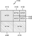
- 4A is a diagram illustrating an example in which intra prediction and inter prediction are mixed in a coding unit according to an embodiment.
- the encoding apparatus 20 and the decoding apparatus 10 may include a coding tree unit (CTU), for example, a square block having a size of 64x64 to 256x256 pixels.
- Intra prediction or inter prediction may be performed by dividing the coding units 4110, 4160, and 4170 in 4100 into smaller coding units 4120, 4130, 4140, and 4150.
- the coding units in the CTU may perform encoding by using intra prediction and inter prediction.
- Weighted bidirectional prediction according to an embodiment may be applied only to coding units 4110, 4130, 4140, and 4150 on which inter prediction is performed. Therefore, weighted bidirectional prediction may be performed when a condition in which the corresponding coding unit performs inter prediction is satisfied. Additional conditions for performing the weighted bidirectional prediction are described below with reference to FIG. 4B.
- 4B is a diagram illustrating a condition under which weighted bidirectional prediction is performed in a prediction unit, according to an embodiment.
- prediction encoding may be performed based on coding units of a final depth, that is, coding units that are no longer split, according to various embodiments.
- a coding unit that is no longer divided based on prediction coding is referred to as a 'prediction unit'.
- the coding unit may perform prediction by at least one prediction unit.
- prediction units PU1 4210, PU2 4220, PU3 4230, and PU4 4240 may exist in a current coding unit 4200 in which inter prediction is performed.
- a difference value between corresponding pixels of reference pictures corresponding to the two motion vectors is predetermined. If not less than the threshold, weighted bidirectional prediction may be performed on PU1 4210. However, if PU2 4220 uses only one motion vector MV0 to predict the sample value of the current region, weighted bidirectional prediction may not be performed on PU2 4220.
- the weighted bidirectional prediction may not be performed on the PU3 4230 and the PU4 4240. In this case, bidirectional prediction using an average value of corresponding pixels of reference pictures corresponding to two motion vectors MV0 and MV1 may be performed.
- the predetermined threshold value may be a value dependent on the quantization parameter for the current prediction unit.
- FIG. 5A illustrates syntax elements for performing weighted bidirectional prediction, according to an embodiment
- FIG. 5B illustrates syntax elements for performing weighted bidirectional prediction, according to another embodiment.
- FIG. 5A illustrates a structure in which an LCU syntax element 5110, a prefix 5120, and an additional syntax element 5130 are included in a maximum coding unit (LCU) structure 5100
- FIG. 5B illustrates a CU in a slice structure 5200. Shows a structure that includes a syntax element 5210, a prefix 5220 and an additional syntax element 5230.
- the syntax elements shown in FIGS. 5A and 5B are included in a parameter set, such as a Video Parameter Set (VPS) or Sequence Parameter Set (SPS) or Picture Parameter Set (PPS). It may be.
- VPS Video Parameter Set
- SPS Sequence Parameter Set
- PPS Picture Parameter Set
- the prefix 5120, 5220 and the additional syntax element 5230 are added after the LCU syntax element 5110 or CU syntax element 5210 in the bitstream. do.
- the LCU syntax element 5110 or the CU syntax element 5210 may include information necessary for decoding an image.
- the prefix may include a first counter value indicating the number of additional syntax elements.
- the prefix may also include a second counter value indicating the number of additional syntax elements including information indicating that weighted bidirectional prediction is performed among the additional syntax elements.
- One or more prefixes according to various embodiments may exist and may include other information required for parsing additional syntax elements in addition to the first counter or the second counter.
- Each of the additional syntax elements according to an embodiment may be configured of two bins for indicating weight information and information on whether to perform weighted bidirectional prediction.
- 6A illustrates a configuration of a prefix according to an embodiment.
- each bin for a block of data may be coded using probability estimates for each bin.
- Probability estimates may represent the likelihood of a bin with a given binary value (eg, “0” or “1”).
- Probability estimates may be included in a probability model, which may also be referred to as a "context model.”
- the image decoding apparatus may select a probabilistic model by determining the context for the bin.
- the context for the bean of the syntax element may include the values of the associated beans of the previously coded neighbor syntax elements.
- the context for a bean of a syntax element may, for example, determine the values of the associated bins of previously coded neighbor syntax elements at the top and left of the current syntax element. It may include. In this case, different probability models are defined for each context. After coding the bin, the probabilistic model is further updated based on the value of the bin to reflect the most recent probability estimates.
- CBP coded block pattern
- the context indicative of a particular probability model for coding a bin may be affected by the values of previously coded bins, such as related bins of previously coded syntax elements.
- the probabilistic model used to code the bin may also be affected by the values of previously coded bins.
- one or more prefixes may include a first prefix 6110 and a second prefix 6120.
- the first prefix 6110 can include a first counter value N that indicates the number of additional syntax elements that follow the main syntax element.
- the second prefix 6120 may include a second counter value N1 indicating the number of additional syntax elements having 1 as the value of the first bin among the additional syntax elements consisting of two sets of bins.
- 6B illustrates a configuration of an additional syntax element according to an embodiment.
- an additional syntax element may be configured with information about whether to perform weighted bidirectional prediction and a set of two bins for indicating weight information.
- the additional syntax element may signal three modes of prediction using the first bin 6210 and the second bin 6220. When the first bin 6210 is 1, it may indicate that weighted bidirectional prediction is performed. When the first bin 6210 is 0, it may indicate that weighted bidirectional prediction is not performed. When weighted bidirectional prediction is performed, a weight value may be determined according to the value of the second bin 6220.
- the second case a blank with a value of zero (6220), and the scale factors for the weighted prediction can be applied to the P 1 instead of P 0, both the scale to a value of 1 when weighted prediction of a second blank (6220)
- the argument can be applied to P 1 instead of P 0 .
- FIG. 7 is a flow chart illustrating a method of obtaining additional syntax elements according to an embodiment.
- the image decoding apparatus 10 may use counter values included in one or more prefixes to obtain additional syntax elements.
- the first counter value N included in at least one prefix indicates the number of additional syntax elements
- the second counter value N1 indicates the number of additional syntax elements having 1 as the value of the first bin among the additional syntax elements (S7100).
- 8A is a flowchart illustrating a method of checking whether to perform weighted bidirectional prediction according to an embodiment.
- the image encoding apparatus 20 and the image decoding apparatus 10 identify a prediction mode, syntax information, and a motion vector of a coding unit (S8100).
- the prediction mode of the coding unit is an intra mode or when there is only one MV0, weighted bidirectional prediction is not performed, and additional syntax elements for the prediction units need not be obtained.
- the motion vectors MV0 and MV1 represent the same reference frame, the difference between MV0 and MV1 is
- MV0 x and MV1 x represent the x component of MV0 and MV1, respectively, and MV0 y and MV1 y represent the y component of MV0 and MV1, respectively.
- bidirectional prediction using an average value is performed (S8400).
- the image encoding apparatus 20 and the image decoding apparatus 10 check the similarity between the reference frames P 0 and P 1 (S8200). If the difference between the corresponding pixel value of P 0 and the corresponding pixel value of P 1
- FIG. 8B is a diagram illustrating a result of performing a similarity check on each pixel in a reference frame.
- weights may be adaptively applied to individual pixels when performing bidirectional prediction.
- bidirectional prediction using an average value may be performed on pixels assigned to "nm”
- bidirectional prediction using a weight may be performed on pixels assigned to "m” (S8300).
- a method of adaptively applying weights to individual pixels when performing bidirectional prediction is referred to as pixel-weighted bidirectional prediction or pixel-weighted bidirectional motion compensation.
- motion compensation is performed by using Equation 3 with respect to the pixel assigned with the value of “m” and Equation 4 with respect to the pixel assigned with the value of “nm”. can do.
- P 0 (i, j) and P 1 (i, j) are prediction pixels of (i, j) coordinates generated using motion vectors in reference pictures L0 and L1, respectively.
- w 0 and w 1 are scale factors for weight prediction of L0 and L1
- offset and offset1 are offset factors for weight prediction
- '>>' is an operator that shifts data in bits to increase or decrease values.
- the bit operator 'a >>b' represents a bit shift and represents an operation of shifting the bit string a to the right by b bits.
- the bit operator 'a >>b' is described in decimal, it is equivalent to dividing the decimal value a by the power of b.
- the image encoding apparatus 20 and the image decoding apparatus 10 may perform weighted bidirectional motion compensation in units of blocks instead of performing the aforementioned weighted bidirectional motion compensation in units of pixels.
- the weighted bidirectional motion compensation on a block basis is a method of performing weighted bidirectional prediction on all pixels in a prediction unit including a pixel to which "m" is assigned. That is, in block-weighted bidirectional prediction according to an embodiment, motion compensation may be performed by applying Equation 5 to all pixels in the prediction unit. Information about the weight value may be included in the additional syntax element.
- the image encoding apparatus 20 and the image decoding apparatus 10 may perform an additional similarity check on each pixel in the reference frame 8500. For example, of the surrounding pixels of the pixel 8510 given the "nm" value, the sum of the values of the surrounding pixels given the "nm” value. If it is smaller than this predetermined threshold value T2, the "nm" value given to the pixel 8510 can be modified to the "m” value. That is, the image encoding apparatus 20 and the image decoding apparatus 10 according to an embodiment may use the values of the neighboring pixels of the pixels to which the "nm" value is assigned when checking the similarity between the reference frames P0 and P1. Since the image encoding apparatus 20 and the image decoding apparatus 10 according to an embodiment perform weighted bidirectional prediction adaptively by checking the similarity between the reference frames P0 and P1 in various ways, the accuracy of encoding and decoding operations is improved. Can be.
- the reference block used when inter prediction is performed may be a coding unit or a prediction unit.
- the coding unit may be one of coding trees hierarchically configured according to the depth.
- a relationship between a coding unit, a prediction unit, and a transformation unit, which are data processing units, will be described with reference to FIGS. 9 to 23.
- FIG. 9 is a block diagram of a video encoding apparatus 100 based on coding units having a tree structure, according to various embodiments.
- the video encoding apparatus 100 including video prediction based on coding units having a tree structure includes a coding unit determiner 120 and an output unit 130.
- the video encoding apparatus 100 that includes video prediction based on coding units having a tree structure is abbreviated as “video encoding apparatus 100”.
- the coding unit determiner 120 may partition the current picture based on a maximum coding unit that is a coding unit having a maximum size for the current picture of the image. If the current picture is larger than the maximum coding unit, image data of the current picture may be split into at least one maximum coding unit.
- the maximum coding unit may be a data unit having a size of 32x32, 64x64, 128x128, 256x256, or the like, and may be a square data unit having a square of two horizontal and vertical sizes.
- Coding units may be characterized by a maximum size and depth.
- the depth indicates the number of times the coding unit is spatially divided from the maximum coding unit, and as the depth increases, the coding unit for each depth may be split from the maximum coding unit to the minimum coding unit.
- the depth of the largest coding unit is the highest depth and the minimum coding unit may be defined as the lowest coding unit.
- the maximum coding unit decreases as the depth increases, the size of the coding unit for each depth decreases, and thus, the coding unit of the higher depth may include coding units of a plurality of lower depths.
- the image data of the current picture may be divided into maximum coding units according to the maximum size of the coding unit, and each maximum coding unit may include coding units divided by depths. Since the maximum coding unit is divided according to depths according to various embodiments, image data of a spatial domain included in the maximum coding unit may be hierarchically classified according to depth.
- the maximum depth and the maximum size of the coding unit that limit the total number of times of hierarchically dividing the height and the width of the maximum coding unit may be preset.
- the coding unit determiner 120 encodes at least one divided region obtained by dividing the region of the largest coding unit for each depth, and determines a depth at which the final encoding result is output for each of the at least one divided region. That is, the coding unit determiner 120 encodes the image data in coding units according to depths for each maximum coding unit of the current picture, and selects the depth at which the smallest coding error occurs to determine the final depth. The determined final depth and the image data for each maximum coding unit are output to the outputter 130.
- Image data in the largest coding unit is encoded based on coding units according to depths according to at least one depth less than or equal to the maximum depth, and encoding results based on the coding units for each depth are compared. As a result of comparing the encoding error of the coding units according to depths, a depth having the smallest encoding error may be selected. At least one final depth may be determined for each maximum coding unit.
- the coding unit is divided into hierarchically and the number of coding units increases.
- a coding error of each data is measured, and whether or not division into a lower depth is determined. Therefore, even in the data included in one largest coding unit, since the encoding error for each depth is different according to the position, the final depth may be differently determined according to the position. Accordingly, one or more final depths may be set for one maximum coding unit, and data of the maximum coding unit may be partitioned according to coding units of one or more final depths.
- the coding unit determiner 120 may determine coding units having a tree structure included in the current maximum coding unit.
- the coding units according to a tree structure according to various embodiments include coding units having a depth determined as a final depth among all deeper coding units included in the current maximum coding unit.
- the coding unit of the final depth may be determined hierarchically according to the depth in the same region within the maximum coding unit, and may be independently determined for the other regions.
- the final depth for the current area can be determined independently of the final depth for the other area.
- the maximum depth according to various embodiments is an index related to the number of divisions from the maximum coding unit to the minimum coding unit.
- the first maximum depth according to various embodiments may indicate the total number of divisions from the maximum coding unit to the minimum coding unit.
- the second maximum depth according to various embodiments may indicate the total number of depth levels from the maximum coding unit to the minimum coding unit. For example, when the depth of the largest coding unit is 0, the depth of the coding unit obtained by dividing the largest coding unit once may be set to 1, and the depth of the coding unit divided twice may be set to 2. In this case, if the coding unit divided four times from the maximum coding unit is the minimum coding unit, since depth levels of 0, 1, 2, 3, and 4 exist, the first maximum depth is set to 4 and the second maximum depth is set to 5. Can be.
- Predictive encoding and transformation of the largest coding unit may be performed. Similarly, prediction encoding and transformation are performed based on depth-wise coding units for each maximum coding unit and for each depth less than or equal to the maximum depth.
- encoding including prediction encoding and transformation should be performed on all the coding units for each depth generated as the depth deepens.
- the prediction encoding and the transformation will be described based on the coding unit of the current depth among at least one maximum coding unit.
- the video encoding apparatus 100 may variously select a size or shape of a data unit for encoding image data.
- the encoding of the image data is performed through prediction encoding, transforming, entropy encoding, and the like.
- the same data unit may be used in every step, or the data unit may be changed in steps.
- the video encoding apparatus 100 may select not only a coding unit for encoding the image data, but also a data unit different from the coding unit in order to perform predictive encoding of the image data in the coding unit.
- prediction encoding may be performed based on coding units of a final depth, that is, coding units that are no longer split, according to various embodiments.
- a coding unit that is no longer divided based on prediction coding is referred to as a 'prediction unit'.
- the partition in which the prediction unit is divided may include a data unit in which at least one of the prediction unit and the height and the width of the prediction unit are divided.
- the partition may be a data unit in which the prediction unit of the coding unit is split, and the prediction unit may be a partition having the same size as the coding unit.
- the partition mode may be formed in a geometric form, as well as partitions divided in an asymmetrical ratio such as 1: n or n: 1, as well as symmetric partitions in which a height or width of a prediction unit is divided in a symmetrical ratio. It may optionally include partitioned partitions, arbitrary types of partitions, and the like.
- the prediction mode of the prediction unit may be at least one of an intra mode, an inter mode, and a skip mode.
- the intra mode and the inter mode may be performed on partitions having sizes of 2N ⁇ 2N, 2N ⁇ N, N ⁇ 2N, and N ⁇ N.
- the skip mode may be performed only for partitions having a size of 2N ⁇ 2N.
- the encoding may be performed independently for each prediction unit within the coding unit to select a prediction mode having the smallest encoding error.
- the video encoding apparatus 100 may perform conversion of image data of a coding unit based on not only a coding unit for encoding image data, but also a data unit different from the coding unit.
- the transformation may be performed based on a transformation unit having a size smaller than or equal to the coding unit.
- the transformation unit may include a data unit for intra mode and a transformation unit for inter mode.
- the transformation unit in the coding unit is also recursively divided into smaller transformation units, so that the residual data of the coding unit is determined according to the tree structure according to the transformation depth. Can be partitioned according to the conversion unit.
- a transformation depth indicating a number of divisions between the height and the width of the coding unit divided to the transformation unit may be set. For example, if the size of the transform unit of the current coding unit of size 2Nx2N is 2Nx2N, the transform depth is 0, the transform depth 1 if the size of the transform unit is NxN, and the transform depth 2 if the size of the transform unit is N / 2xN / 2. Can be. That is, the transformation unit having a tree structure may also be set for the transformation unit according to the transformation depth.
- the split information for each depth requires not only depth but also prediction related information and transformation related information. Accordingly, the coding unit determiner 120 may determine not only the depth that generates the minimum coding error, but also a partition mode in which the prediction unit is divided into partitions, a prediction mode for each prediction unit, and a size of a transformation unit for transformation.
- a method of determining a coding unit, a prediction unit / partition, and a transformation unit according to a tree structure of a maximum coding unit according to various embodiments will be described in detail with reference to FIGS. 9 to 19.
- the coding unit determiner 120 may measure a coding error of coding units according to depths using a Lagrangian Multiplier-based rate-distortion optimization technique.
- the output unit 130 outputs the image data and the split information according to depths of the maximum coding unit, which are encoded based on at least one depth determined by the coding unit determiner 120, in a bitstream form.
- the encoded image data may be a result of encoding residual data of the image.
- the split information for each depth may include depth information, partition mode information of a prediction unit, prediction mode information, split information of a transformation unit, and the like.
- the final depth information may be defined using depth-specific segmentation information indicating whether to encode in a coding unit of a lower depth rather than encoding the current depth. If the current depth of the current coding unit is a depth, since the current coding unit is encoded in a coding unit of the current depth, split information of the current depth may be defined so that it is no longer divided into lower depths. On the contrary, if the current depth of the current coding unit is not the depth, encoding should be attempted using the coding unit of the lower depth, and thus split information of the current depth may be defined to be divided into coding units of the lower depth.
- encoding is performed on the coding unit divided into the coding units of the lower depth. Since at least one coding unit of a lower depth exists in the coding unit of the current depth, encoding may be repeatedly performed for each coding unit of each lower depth, and recursive coding may be performed for each coding unit of the same depth.
- coding units having a tree structure are determined in one largest coding unit and at least one split information should be determined for each coding unit of a depth, at least one split information may be determined for one maximum coding unit.
- the depth since the data of the largest coding unit is partitioned hierarchically according to the depth, the depth may be different for each location, and thus depth and split information may be set for the data.
- the output unit 130 may allocate encoding information about a corresponding depth and an encoding mode to at least one of a coding unit, a prediction unit, and a minimum unit included in the maximum coding unit.
- a minimum unit is a square data unit of a size obtained by dividing a minimum coding unit, which is a lowest depth, into four segments.
- the minimum unit may be a square data unit having a maximum size that may be included in all coding units, prediction units, partition units, and transformation units included in the maximum coding unit.
- the encoding information output through the output unit 130 may be classified into encoding information according to depth coding units and encoding information according to prediction units.
- the encoding information for each coding unit according to depth may include prediction mode information and partition size information.
- the encoding information transmitted for each prediction unit includes information about an estimation direction of the inter mode, information about a reference image index of the inter mode, information about a motion vector, information about a chroma component of an intra mode, and information about an inter mode of an intra mode. And the like.
- Information about the maximum size and information about the maximum depth of the coding unit defined for each picture, slice, or GOP may be inserted into a header, a sequence parameter set, or a picture parameter set of the bitstream.
- the information on the maximum size of the transform unit and the minimum size of the transform unit allowed for the current video may also be output through a header, a sequence parameter set, a picture parameter set, or the like of the bitstream.
- the output unit 130 may encode and output reference information, motion information, and slice type information related to prediction.
- a coding unit according to depths is a coding unit having a size in which a height and a width of a coding unit of one layer higher depth are divided by half. That is, if the size of the coding unit of the current depth is 2Nx2N, the size of the coding unit of the lower depth is NxN.
- the current coding unit having a size of 2N ⁇ 2N may include up to four lower depth coding units having a size of N ⁇ N.
- the video encoding apparatus 100 determines a coding unit having an optimal shape and size for each maximum coding unit based on the size and the maximum depth of the maximum coding unit determined in consideration of the characteristics of the current picture. Coding units may be configured. In addition, since each of the maximum coding units may be encoded in various prediction modes and transformation methods, an optimal coding mode may be determined in consideration of image characteristics of coding units having various image sizes.
- the video encoding apparatus may increase the maximum size of the coding unit in consideration of the size of the image and adjust the coding unit in consideration of the image characteristic, thereby increasing image compression efficiency.
- FIG. 10 is a block diagram of a video decoding apparatus 200 based on coding units having a tree structure, according to various embodiments.
- a video decoding apparatus 200 including video prediction based on coding units having a tree structure includes a receiver 210, image data and encoding information extractor 220, and image data decoder 230. do.
- the video decoding apparatus 200 that includes video prediction based on coding units having a tree structure is abbreviated as “video decoding apparatus 200”.
- the receiver 210 receives and parses a bitstream of an encoded video.
- the image data and encoding information extractor 220 extracts image data encoded for each coding unit from the parsed bitstream according to coding units having a tree structure for each maximum coding unit, and outputs the encoded image data to the image data decoder 230.
- the image data and encoding information extractor 220 may extract information about a maximum size of a coding unit of the current picture from a header, a sequence parameter set, or a picture parameter set for the current picture.
- the image data and encoding information extractor 220 extracts the final depth and the split information of the coding units having a tree structure for each maximum coding unit from the parsed bitstream.
- the extracted final depth and split information are output to the image data decoder 230. That is, the image data of the bit string may be divided into maximum coding units so that the image data decoder 230 may decode the image data for each maximum coding unit.
- the depth and split information for each largest coding unit may be set for one or more depth information, and the split information for each depth may include partition mode information, prediction mode information, split information of a transform unit, and the like, of a corresponding coding unit. .
- depth-specific segmentation information may be extracted.
- the depth and split information for each largest coding unit extracted by the image data and encoding information extractor 220 are repeatedly repeated for each coding unit for each deeper coding unit, as in the video encoding apparatus 100 according to various embodiments. Depth and split information determined to perform encoding to generate a minimum encoding error. Therefore, the video decoding apparatus 200 may reconstruct an image by decoding data according to an encoding method that generates a minimum encoding error.
- the image data and encoding information extractor 220 may determine the predetermined data unit. Depth and segmentation information can be extracted for each. If the depth and the split information of the corresponding maximum coding unit are recorded for each predetermined data unit, the predetermined data units having the same depth and the split information may be inferred as data units included in the same maximum coding unit.
- the image data decoder 230 reconstructs the current picture by decoding image data of each maximum coding unit based on the depth and the split information for each maximum coding unit. That is, the image data decoder 230 may decode the encoded image data based on the read partition mode, the prediction mode, and the transformation unit for each coding unit among the coding units having the tree structure included in the maximum coding unit. Can be.
- the decoding process may include a prediction process including intra prediction and motion compensation, and an inverse transform process.
- the image data decoder 230 may perform intra prediction or motion compensation according to each partition and prediction mode for each coding unit, based on the partition mode information and the prediction mode information of the prediction unit of the coding unit according to depths.
- the image data decoder 230 may read transform unit information having a tree structure for each coding unit, and perform inverse transform based on the transformation unit for each coding unit, for inverse transformation for each largest coding unit. Through inverse transformation, the pixel value of the spatial region of the coding unit may be restored.
- the image data decoder 230 may determine the depth of the current maximum coding unit by using the split information for each depth. If the split information indicates that the split information is no longer divided at the current depth, the current depth is the depth. Therefore, the image data decoder 230 may decode the coding unit of the current depth using the partition mode, the prediction mode, and the transformation unit size information of the prediction unit, for the image data of the current maximum coding unit.
- the image data decoder 230 It may be regarded as one data unit to be decoded in the same encoding mode.
- the decoding of the current coding unit may be performed by obtaining information about an encoding mode for each coding unit determined in this way.
- the video decoding apparatus 200 may obtain information about a coding unit that generates a minimum coding error by recursively encoding each maximum coding unit in the encoding process, and use the same to decode the current picture. That is, decoding of encoded image data of coding units having a tree structure determined as an optimal coding unit for each maximum coding unit can be performed.
- the image data is efficiently decoded according to the size and encoding mode of a coding unit adaptively determined according to the characteristics of the image using the optimal split information transmitted from the encoding end. Can be restored
- FIG. 11 illustrates a concept of coding units, according to various embodiments.
- a size of a coding unit may be expressed by a width x height, and may include 32x32, 16x16, and 8x8 from a coding unit having a size of 64x64.
- Coding units of size 64x64 may be partitioned into partitions of size 64x64, 64x32, 32x64, and 32x32, coding units of size 32x32 are partitions of size 32x32, 32x16, 16x32, and 16x16, and coding units of size 16x16 are 16x16.
- Coding units of size 8x8 may be divided into partitions of size 8x8, 8x4, 4x8, and 4x4, into partitions of 16x8, 8x16, and 8x8.
- the resolution is set to 1920x1080, the maximum size of the coding unit is 64, and the maximum depth is 2.
- the resolution is set to 1920x1080, the maximum size of the coding unit is 64, and the maximum depth is 3.
- the resolution is set to 352x288, the maximum size of the coding unit is 16, and the maximum depth is 1.
- the maximum depth illustrated in FIG. 11 represents the total number of divisions from the maximum coding unit to the minimum coding unit.
- the maximum size of the coding size is relatively large not only to improve the coding efficiency but also to accurately shape the image characteristics. Accordingly, the video data 310 or 320 having a higher resolution than the video data 330 may be selected to have a maximum size of 64.
- the coding unit 315 of the video data 310 is divided twice from a maximum coding unit having a long axis size of 64, and the depth is deepened by two layers, so that the long axis size is 32, 16. Up to coding units may be included.
- the coding unit 335 of the video data 330 is divided once from coding units having a long axis size of 16, and the depth is deepened by one layer to increase the long axis size to 8. Up to coding units may be included.
- the coding unit 325 of the video data 320 is divided three times from the largest coding unit having a long axis size of 64, and the depth is three layers deep, so that the long axis size is 32, 16. , Up to 8 coding units may be included. As the depth increases, the expressive power of the detailed information may be improved.
- FIG. 12 is a block diagram of an image encoder 400 based on coding units, according to various embodiments.
- the image encoder 400 performs operations performed by the picture encoder 120 of the video encoding apparatus 100 to encode image data. That is, the intra prediction unit 420 performs intra prediction on each coding unit of the intra mode of the current image 405, and the inter prediction unit 415 performs the current image on the prediction unit of the coding unit of the inter mode. Inter-prediction is performed using the reference image acquired at 405 and the reconstructed picture buffer 410.
- the current image 405 may be divided into maximum coding units and then sequentially encoded. In this case, encoding may be performed on the coding unit in which the largest coding unit is to be divided into a tree structure.
- Residual data is generated by subtracting the prediction data for the coding unit of each mode output from the intra prediction unit 420 or the inter prediction unit 415 from the data for the encoding unit of the current image 405, and
- the dew data is output as transform coefficients quantized for each transform unit through the transform unit 425 and the quantization unit 430.
- the quantized transform coefficients are reconstructed into residue data in the spatial domain through the inverse quantizer 445 and the inverse transformer 450.
- Residual data of the reconstructed spatial domain is added to the prediction data of the coding unit of each mode output from the intra predictor 420 or the inter predictor 415, thereby adding the residual data of the spatial domain to the coding unit of the current image 405. The data is restored.
- the reconstructed spatial region data is generated as a reconstructed image through the deblocking unit 455 and the SAO performing unit 460.
- the generated reconstructed image is stored in the reconstructed picture buffer 410.
- the reconstructed images stored in the reconstructed picture buffer 410 may be used as reference images for inter prediction of another image.
- the transform coefficients quantized by the transformer 425 and the quantizer 430 may be output as the bitstream 440 through the entropy encoder 435.
- the inter predictor 415, the intra predictor 420, and the transformer each have a tree structure for each maximum coding unit. An operation based on each coding unit among the coding units may be performed.
- the intra prediction unit 420 and the inter prediction unit 415 determine the partition mode and the prediction mode of each coding unit among the coding units having a tree structure in consideration of the maximum size and the maximum depth of the current maximum coding unit.
- the transform unit 425 may determine whether to split the transform unit according to the quad tree in each coding unit among the coding units having the tree structure.
- FIG. 13 is a block diagram of an image decoder 500 based on coding units, according to various embodiments.
- the entropy decoding unit 515 parses the encoded image data to be decoded from the bitstream 505 and encoding information necessary for decoding.
- the encoded image data is a quantized transform coefficient
- the inverse quantizer 520 and the inverse transform unit 525 reconstruct residue data from the quantized transform coefficients.
- the intra prediction unit 540 performs intra prediction for each prediction unit with respect to the coding unit of the intra mode.
- the inter prediction unit 535 performs inter prediction using the reference image obtained from the reconstructed picture buffer 530 for each coding unit of the coding mode of the inter mode among the current pictures.
- the data of the spatial domain of the coding unit of the current image 405 is reconstructed and restored.
- the data of the space area may be output as a reconstructed image 560 via the deblocking unit 545 and the SAO performing unit 550.
- the reconstructed images stored in the reconstructed picture buffer 530 may be output as reference images.
- step-by-step operations after the entropy decoder 515 of the image decoder 500 may be performed.
- the entropy decoder 515, the inverse quantizer 520, and the inverse transformer ( 525, the intra prediction unit 540, the inter prediction unit 535, the deblocking unit 545, and the SAO performer 550 based on each coding unit among coding units having a tree structure for each maximum coding unit. You can do it.
- the intra predictor 540 and the inter predictor 535 determine a partition mode and a prediction mode for each coding unit among coding units having a tree structure, and the inverse transformer 525 has a quad tree structure for each coding unit. It is possible to determine whether to divide the conversion unit according to.
- the inter prediction unit 415 of FIG. 12 and the inter prediction unit 535 of FIG. 13 may generate a sample value of a subpixel unit when a motion vector indicates a subpixel position for inter prediction.
- Interpolation filtering may be performed on the reference samples in units of integer pixels. As described above with reference to FIGS. 1 to 9, based on the degree of change between reference samples, an all-pass interpolation filter capable of preserving low frequency components and high frequency components is selected from interpolation filters, or only preservation of low frequency components is performed. If necessary, an interpolation filter for low frequency band pass may be selected.
- FIG. 14 is a diagram illustrating deeper coding units according to depths, and partitions, according to various embodiments.
- the video encoding apparatus 100 according to various embodiments and the video decoding apparatus 200 according to various embodiments use hierarchical coding units to consider image characteristics.
- the maximum height, width, and maximum depth of the coding unit may be adaptively determined according to the characteristics of the image, and may be variously set according to a user's request. According to the maximum size of the preset coding unit, the size of the coding unit for each depth may be determined.
- the hierarchical structure 600 of a coding unit illustrates a case in which a maximum height and a width of a coding unit are 64 and a maximum depth is three.
- the maximum depth indicates the total number of divisions from the maximum coding unit to the minimum coding unit. Since the depth deepens along the vertical axis of the hierarchical structure 600 of the coding unit according to various embodiments, the height and the width of the coding unit for each depth are divided.
- a prediction unit and a partition on which the prediction encoding of each depth-based coding unit is shown along the horizontal axis of the hierarchical structure 600 of the coding unit are illustrated.
- the coding unit 610 has a depth of 0 as the largest coding unit of the hierarchical structure 600 of the coding unit, and the size, ie, the height and width, of the coding unit is 64x64.
- a depth deeper along the vertical axis includes a coding unit 620 of depth 1 having a size of 32x32, a coding unit 630 of depth 2 having a size of 16x16, and a coding unit 640 of depth 3 having a size of 8x8.
- a coding unit 640 of depth 3 having a size of 8 ⁇ 8 is a minimum coding unit.
- Prediction units and partitions of the coding unit are arranged along the horizontal axis for each depth. That is, if the coding unit 610 of size 64x64 having a depth of zero is a prediction unit, the prediction unit may include a partition 610 of size 64x64, partitions 612 of size 64x32, and size included in the coding unit 610 of size 64x64. 32x64 partitions 614, 32x32 partitions 616.
- the prediction unit of the coding unit 620 having a size of 32x32 having a depth of 1 includes a partition 620 of size 32x32, partitions 622 of size 32x16 and a partition of size 16x32 included in the coding unit 620 of size 32x32. 624, partitions 626 of size 16x16.
- the prediction unit of the coding unit 630 of size 16x16 having a depth of 2 includes a partition 630 of size 16x16, partitions 632 of size 16x8, and a partition of size 8x16 included in the coding unit 630 of size 16x16. 634, partitions 636 of size 8x8.
- the prediction unit of the coding unit 640 of size 8x8 having a depth of 3 includes a partition 640 of size 8x8, partitions 642 of size 8x4 and a partition of size 4x8 included in the coding unit 640 of size 8x8. 644, partitions 646 of size 4x4.
- the coding unit determiner 120 of the video encoding apparatus 100 may determine the depth of the maximum coding unit 610 for each coding unit of each depth included in the maximum coding unit 610. Encoding must be performed.
- the number of deeper coding units according to depths for including data having the same range and size increases as the depth increases. For example, four coding units of depth 2 are required for data included in one coding unit of depth 1. Therefore, in order to compare the encoding results of the same data for each depth, each of the coding units having one depth 1 and four coding units having four depths 2 should be encoded.
- encoding may be performed for each prediction unit of a coding unit according to depths along a horizontal axis of the hierarchical structure 600 of the coding unit, and a representative coding error, which is the smallest coding error at a corresponding depth, may be selected. .
- a depth deeper along the vertical axis of the hierarchical structure 600 of the coding unit the encoding may be performed for each depth, and the minimum coding error may be searched by comparing the representative coding error for each depth.
- the depth and partition in which the minimum coding error occurs in the maximum coding unit 610 may be selected as the depth and partition mode of the maximum coding unit 610.
- 15 illustrates a relationship between a coding unit and transformation units, according to various embodiments.
- the video encoding apparatus 100 encodes or decodes an image in coding units having a size smaller than or equal to the maximum coding unit for each maximum coding unit.
- the size of a transformation unit for transformation in the encoding process may be selected based on a data unit that is not larger than each coding unit.
- the 32x32 transform unit 720 may be selected. The conversion can be performed.
- the data of the 64x64 coding unit 710 is transformed into 32x32, 16x16, 8x8, and 4x4 transform units of 64x64 size or less, and then encoded, and the transform unit having the least error with the original is selected. Can be.
- 16 illustrates encoding information, according to various embodiments.
- the output unit 130 of the video encoding apparatus 100 is split information, and information about a partition mode 800, information 810 about a prediction mode, and transform unit size for each coding unit of each depth.
- Information 820 may be encoded and transmitted.
- the information about the partition mode 800 is a data unit for predictive encoding of the current coding unit and indicates information about a partition type in which the prediction unit of the current coding unit is divided.
- the current coding unit CU_0 of size 2Nx2N may be any one of a partition 802 of size 2Nx2N, a partition 804 of size 2NxN, a partition 806 of size Nx2N, and a partition 808 of size NxN. It can be divided and used.
- the information 800 about the partition mode of the current coding unit represents one of a partition 802 of size 2Nx2N, a partition 804 of size 2NxN, a partition 806 of size Nx2N, and a partition 808 of size NxN. It is set to.
- Information 810 relating to the prediction mode indicates the prediction mode of each partition. For example, through the information 810 about the prediction mode, whether the partition indicated by the information 800 about the partition mode is performed in one of the intra mode 812, the inter mode 814, and the skip mode 816 is performed. Whether or not can be set.
- the information about the transform unit size 820 indicates whether to transform the current coding unit based on the transform unit.
- the transform unit may be one of a first intra transform unit size 822, a second intra transform unit size 824, a first inter transform unit size 826, and a second inter transform unit size 828. have.
- the image data and encoding information extractor 210 of the video decoding apparatus 200 may include information about a partition mode 800, information 810 about a prediction mode, and transformation for each depth-based coding unit. Information 820 about the unit size may be extracted and used for decoding.
- 17 is a diagram illustrating deeper coding units according to depths, according to various embodiments.
- Segmentation information may be used to indicate a change in depth.
- the split information indicates whether a coding unit of a current depth is split into coding units of a lower depth.
- the prediction unit 910 for predictive encoding of the coding unit 900 having depth 0 and 2N_0x2N_0 size includes a partition mode 912 of 2N_0x2N_0 size, a partition mode 914 of 2N_0xN_0 size, a partition mode 916 of N_0x2N_0 size, and N_0xN_0 May include a partition mode 918 of size.
- partition mode 912, 914, 916, and 918 in which the prediction unit is divided by a symmetrical ratio are illustrated, as described above, the partition mode is not limited thereto, and asymmetric partitions, arbitrary partitions, geometric partitions, and the like. It may include.
- prediction coding For each partition mode, prediction coding must be performed repeatedly for one 2N_0x2N_0 partition, two 2N_0xN_0 partitions, two N_0x2N_0 partitions, and four N_0xN_0 partitions.
- prediction encoding For partitions having a size 2N_0x2N_0, a size N_0x2N_0, a size 2N_0xN_0, and a size N_0xN_0, prediction encoding may be performed in an intra mode and an inter mode.
- the skip mode may be performed only for prediction encoding on partitions having a size of 2N_0x2N_0.
- the depth 0 is changed to 1 and split (920), and the encoding is repeatedly performed on the depth 2 and the coding units 930 of the partition mode of size N_0xN_0.
- the depth 1 is changed to the depth 2 and split (950), and repeatedly for the depth 2 and the coding units 960 of the size N_2xN_2.
- the encoding may be performed to search for a minimum encoding error.
- depth-based coding units may be set until depth d-1, and split information may be set up to depth d-2. That is, when encoding is performed from the depth d-2 to the depth d-1 to the depth d-1, the prediction encoding of the coding unit 980 of the depth d-1 and the size 2N_ (d-1) x2N_ (d-1)
- the prediction unit for 990 is a partition mode 992 of size 2N_ (d-1) x2N_ (d-1), a partition mode 994 of size 2N_ (d-1) xN_ (d-1), and size
- a partition mode 996 of N_ (d-1) x2N_ (d-1) and a partition mode 998 of size N_ (d-1) xN_ (d-1) may be included.
- partition mode one partition 2N_ (d-1) x2N_ (d-1), two partitions 2N_ (d-1) xN_ (d-1), two sizes N_ (d-1) x2N_
- a partition mode in which a minimum encoding error occurs may be searched.
- the coding unit CU_ (d-1) of the depth d-1 is no longer
- the depth of the current maximum coding unit 900 may be determined as the depth d-1, and the partition mode may be determined as N_ (d-1) xN_ (d-1) without going through a division process into lower depths.
- split information is not set for the coding unit 952 having the depth d-1.
- the data unit 999 may be referred to as a 'minimum unit' for the current maximum coding unit.
- the minimum unit may be a square data unit having a size obtained by dividing a minimum coding unit, which is a lowest depth, into four divisions.
- the video encoding apparatus 100 compares the encoding errors for each depth of the coding unit 900, selects the depth at which the smallest encoding error occurs, and determines the depth.
- the partition mode and the prediction mode may be set to the encoding mode of the depth.
- depths with the smallest error can be determined by comparing the minimum coding errors for all depths of depths 0, 1, ..., d-1, and d.
- the depth, the partition mode of the prediction unit, and the prediction mode may be encoded and transmitted as split information.
- the coding unit since the coding unit must be split from the depth 0 to the depth, only the split information of the depth is set to '0', and the split information for each depth except the depth should be set to '1'.
- the image data and encoding information extractor 220 of the video decoding apparatus 200 may extract information about a depth and a prediction unit of the coding unit 900 and use the same to decode the coding unit 912. have.
- the video decoding apparatus 200 may grasp the depth of which the split information is '0' as the depth by using the split information for each depth, and may use the split information for the corresponding depth for decoding.
- 18, 19, and 20 illustrate a relationship between coding units, prediction units, and transformation units, according to various embodiments.
- the coding units 1010 are deeper coding units determined by the video encoding apparatus 100 according to various embodiments with respect to the maximum coding unit.
- the prediction unit 1060 is partitions of prediction units of each deeper coding unit among the coding units 1010, and the transform unit 1070 is transform units of each deeper coding unit.
- the depth-based coding units 1010 have a depth of 0
- the coding units 1012 and 1054 have a depth of 1
- the coding units 1014, 1016, 1018, 1028, 1050, and 1052 have depths.
- coding units 1020, 1022, 1024, 1026, 1030, 1032, and 1048 have a depth of three
- coding units 1040, 1042, 1044, and 1046 have a depth of four.
- partitions 1014, 1016, 1022, 1032, 1048, 1050, 1052, and 1054 of the prediction units 1060 are obtained by splitting coding units. That is, partitions 1014, 1022, 1050, and 1054 are 2NxN partition modes, partitions 1016, 1048, and 1052 are Nx2N partition modes, and partitions 1032 are NxN partition modes. Prediction units and partitions of the coding units 1010 according to depths are smaller than or equal to each coding unit.
- the image data of the part 1052 of the transformation units 1070 is transformed or inversely transformed into a data unit having a smaller size than the coding unit.
- the transformation units 1014, 1016, 1022, 1032, 1048, 1050, 1052, and 1054 are data units having different sizes or shapes when compared to corresponding prediction units and partitions among the prediction units 1060. That is, the video encoding apparatus 100 according to various embodiments and the video decoding apparatus 200 according to an embodiment may be intra prediction / motion estimation / motion compensation operations and transform / inverse transform operations for the same coding unit. Each can be performed on a separate data unit.
- coding is performed recursively for each coding unit having a hierarchical structure for each largest coding unit to determine an optimal coding unit.
- coding units having a recursive tree structure may be configured.
- the encoding information may include split information about the coding unit, partition mode information, prediction mode information, and transformation unit size information. Table 1 below shows an example that can be set in the video encoding apparatus 100 according to various embodiments and the video decoding apparatus 200 according to various embodiments.
- the output unit 130 of the video encoding apparatus 100 outputs encoding information about coding units having a tree structure, and the encoding information extracting unit of the video decoding apparatus 200 according to various embodiments of the present disclosure.
- 220 may extract encoding information about coding units having a tree structure from the received bitstream.
- the split information indicates whether the current coding unit is split into coding units of a lower depth. If the split information of the current depth d is 0, partition mode information, prediction mode, and transform unit size information may be defined for the depth since the current coding unit is a depth in which the current coding unit is no longer divided into lower coding units. have. If it is to be further split by the split information, encoding should be performed independently for each coding unit of the divided four lower depths.
- the prediction mode may be represented by one of an intra mode, an inter mode, and a skip mode.
- Intra mode and inter mode can be defined in all partition modes, and skip mode can only be defined in partition mode 2Nx2N.
- the partition mode information indicates symmetric partition modes 2Nx2N, 2NxN, Nx2N, and NxN, in which the height or width of the prediction unit is divided by symmetrical ratios, and asymmetric partition modes 2NxnU, 2NxnD, nLx2N, nRx2N, divided by asymmetrical ratios.
- the asymmetric partition modes 2NxnU and 2NxnD are divided into heights of 1: 3 and 3: 1, respectively, and the asymmetric partition modes nLx2N and nRx2N are divided into 1: 3 and 3: 1 widths, respectively.
- the conversion unit size may be set to two kinds of sizes in the intra mode and two kinds of sizes in the inter mode. That is, if the transformation unit split information is 0, the size of the transformation unit is set to the size 2Nx2N of the current coding unit. If the transform unit split information is 1, a transform unit having a size obtained by dividing the current coding unit may be set. In addition, if the partition mode for the current coding unit having a size of 2Nx2N is a symmetric partition mode, the size of the transform unit may be set to NxN, and N / 2xN / 2 if it is an asymmetric partition mode.
- Encoding information of coding units having a tree structure may be allocated to at least one of a coding unit, a prediction unit, and a minimum unit unit of a depth.
- the coding unit of the depth may include at least one prediction unit and at least one minimum unit having the same encoding information.
- the encoding information held by each adjacent data unit is checked, it may be determined whether the data is included in the coding unit having the same depth.
- the coding unit of the corresponding depth may be identified using the encoding information held by the data unit, the distribution of depths within the maximum coding unit may be inferred.
- the encoding information of the data unit in the depth-specific coding unit adjacent to the current coding unit may be directly referenced and used.
- the prediction coding when the prediction coding is performed by referring to the neighboring coding unit, the data adjacent to the current coding unit in the coding unit according to depths is encoded by using the encoding information of the adjacent coding units according to depths.
- the neighboring coding unit may be referred to by searching.
- FIG. 21 illustrates a relationship between coding units, prediction units, and transformation units, according to encoding mode information of Table 1.
- FIG. 21 illustrates a relationship between coding units, prediction units, and transformation units, according to encoding mode information of Table 1.
- the maximum coding unit 1300 includes coding units 1302, 1304, 1306, 1312, 1314, 1316, and 1318 of depths. Since one coding unit 1318 is a coding unit of depth, split information may be set to zero.
- the partition mode information of the coding unit 1318 having a size of 2Nx2N includes partition modes 2Nx2N 1322, 2NxN 1324, Nx2N 1326, NxN 1328, 2NxnU 1332, 2NxnD 1334, and nLx2N 1336. And nRx2N 1338.
- the transform unit split information (TU size flag) is a type of transform index, and a size of a transform unit corresponding to the transform index may be changed according to a prediction unit type or a partition mode of the coding unit.
- the partition mode information is set to one of symmetric partition modes 2Nx2N 1322, 2NxN 1324, Nx2N 1326, and NxN 1328
- the conversion unit partition information is 0, a conversion unit of size 2Nx2N ( 1342 is set, and if the transform unit split information is 1, a transform unit 1344 of size NxN may be set.
- partition mode information is set to one of asymmetric partition modes 2NxnU (1332), 2NxnD (1334), nLx2N (1336), and nRx2N (1338), if the conversion unit partition information (TU size flag) is 0, a conversion unit of size 2Nx2N ( 1352 is set, and if the transform unit split information is 1, a transform unit 1354 of size N / 2 ⁇ N / 2 may be set.
- the conversion unit splitting information (TU size flag) described above with reference to FIG. 20 is a flag having a value of 0 or 1
- the conversion unit splitting information according to various embodiments is not limited to a 1-bit flag and is set to 0 according to a setting. , 1, 2, 3., etc., and may be divided hierarchically.
- the transformation unit partition information may be used as an embodiment of the transformation index.
- the size of the transformation unit actually used may be expressed.
- the video encoding apparatus 100 may encode maximum transform unit size information, minimum transform unit size information, and maximum transform unit split information.
- the encoded maximum transform unit size information, minimum transform unit size information, and maximum transform unit split information may be inserted into the SPS.
- the video decoding apparatus 200 may use the maximum transform unit size information, the minimum transform unit size information, and the maximum transform unit split information to use for video decoding.
- the maximum transform unit split information is defined as 'MaxTransformSizeIndex'
- the minimum transform unit size is 'MinTransformSize'
- the transform unit split information is 0,
- the minimum transform unit possible in the current coding unit is defined as 'RootTuSize'.
- the size 'CurrMinTuSize' can be defined as in relation (1) below.
- 'RootTuSize' which is a transform unit size when the transform unit split information is 0, may indicate a maximum transform unit size that can be adopted in the system. That is, according to relation (1), 'RootTuSize / (2 ⁇ MaxTransformSizeIndex)' is a transformation obtained by dividing 'RootTuSize', which is the size of the transformation unit when the transformation unit division information is 0, by the number of times corresponding to the maximum transformation unit division information. Since the unit size is 'MinTransformSize' is the minimum transform unit size, a smaller value among them may be the minimum transform unit size 'CurrMinTuSize' possible in the current coding unit.
- RootTuSize may vary depending on the prediction mode.
- RootTuSize may be determined according to the following relation (2).
- 'MaxTransformSize' represents the maximum transform unit size
- 'PUSize' represents the current prediction unit size.
- RootTuSize min (MaxTransformSize, PUSize) ......... (2)
- 'RootTuSize' which is a transform unit size when the transform unit split information is 0, may be set to a smaller value among the maximum transform unit size and the current prediction unit size.
- 'RootTuSize' may be determined according to Equation (3) below.
- 'PartitionSize' represents the size of the current partition unit.
- RootTuSize min (MaxTransformSize, PartitionSize) ........... (3)
- the conversion unit size 'RootTuSize' when the conversion unit split information is 0 may be set to a smaller value among the maximum conversion unit size and the current partition unit size.
- the current maximum conversion unit size 'RootTuSize' according to various embodiments that vary according to the prediction mode of the partition unit is only an embodiment, and a factor determining the current maximum conversion unit size is not limited thereto.
- image data of the spatial domain is encoded for each coding unit of the tree structure, and the video decoding method based on the coding units of the tree structure.
- decoding is performed for each largest coding unit, and image data of a spatial region may be reconstructed to reconstruct a picture and a video that is a picture sequence.
- the reconstructed video can be played back by a playback device, stored in a storage medium, or transmitted over a network.
- the above-described embodiments of the present disclosure may be written as a program executable on a computer, and may be implemented in a general-purpose digital computer operating the program using a computer-readable recording medium.
- the computer-readable recording medium may include a storage medium such as a magnetic storage medium (eg, a ROM, a floppy disk, a hard disk, etc.) and an optical reading medium (eg, a CD-ROM, a DVD, etc.).
- the inter-layer video encoding method and / or video encoding method described above with reference to FIGS. 1A through 22 are collectively referred to as a video encoding method of the present disclosure.
- the inter-layer video decoding method and / or video decoding method described above with reference to FIGS. 1A to 22 are referred to as a video decoding method of the present disclosure.
- a video encoding apparatus including the multilayer video encoding apparatus 10, the video encoding apparatus 100, or the image encoding unit 400 described above with reference to FIGS. 1A to 22 may be referred to as a “video encoding apparatus of the present disclosure”.
- a video decoding apparatus including the multilayer video decoding apparatus 20, the video decoding apparatus 200, or the image decoding unit 500 described above with reference to FIGS. 1A to 22 may be referred to as a video decoding apparatus of the present disclosure.
- the invention can also be embodied as computer readable code on a computer readable recording medium.
- the computer-readable recording medium includes all kinds of recording devices in which data that can be read by a computer system is stored. Examples of computer-readable recording media include ROM, RAM, CD-ROM, magnetic tape, floppy disk, optical data storage device, and the like.
- the computer readable recording medium can also be distributed over network coupled computer systems so that the computer readable code is stored and executed in a distributed fashion.
Landscapes
- Engineering & Computer Science (AREA)
- Multimedia (AREA)
- Signal Processing (AREA)
- Compression Or Coding Systems Of Tv Signals (AREA)
Abstract
Description

| 분할 정보 0 (현재 심도 d의 크기 2Nx2N의 부호화 단위에 대한 부호화) | 분할 정보 1 | ||||
| 예측 모드 | 파티션 모드 | 변환 단위 크기 | 하위 심도 d+1의 부호화 단위들마다 반복적 부호화 | ||
| 인트라 인터스킵 (2Nx2N만) | 대칭형 파티션 모드 | 비대칭형 파티션 모드 | 변환 단위 분할 정보 0 | 변환 단위 분할 정보 1 | |
| 2Nx2N2NxNNx2NNxN | 2NxnU2NxnDnLx2NnRx2N | 2Nx2N | NxN (대칭형 파티션 모드) N/2xN/2 (비대칭형 파티션 모드) | ||
Claims (15)
- 수신한 비트스트림으로부터 주 신택스 요소들(main syntax elements)에 후속하는 부가 신택스 요소들(additional syntax elements)의 개수를 나타내는 제 1 카운터 값을 포함하는 하나 이상의 프리픽스(prefix)를 획득하는 단계;상기 하나 이상의 프리픽스에 기초하여, 현재 블록의 예측을 위해 구분된 예측 단위들의 가중치 양방향 예측(Weighted Bi-Prediction)의 수행 여부에 관한 정보 및 가중치 정보를 포함하는 상기 부가 신택스 요소들을 획득하는 단계; 및상기 주 신택스 요소들 및 상기 부가 신택스 요소들에 기초하여 예측 값을 포함하는 예측 블록을 생성하는 단계를 포함하는, 영상 복호화 방법.
- 제 1 항에 있어서,상기 부가 신택스 요소들의 각각은 상기 가중치 양방향 예측의 수행 여부에 관한 정보 및 상기 가중치 정보를 나타내기 위한 2개의 빈(bin)의 세트로 구성된, 영상 복호화 방법.
- 제 2 항에 있어서,상기 하나 이상의 프리픽스는 상기 부가 신택스 요소들 중 상기 가중치 양방향 예측을 수행함을 나타내는 정보가 포함된 부가 신택스 요소의 개수를 나타내는 제 2 카운터 값을 포함하는, 영상 복호화 방법.
- 제 3 항에 있어서,상기 부가 신택스 요소들을 획득하는 단계는,상기 제 1 카운터 값 및 상기 제 2 카운터 값에 기초하여 상기 부가 신택스 요소들의 빈의 확률 정보를 결정하는 단계; 및상기 확률 정보에 기초하여 상기 부가 신택스 요소들의 빈을 순차적으로 복호화하는 단계를 포함하는, 영상 복호화 방법.
- 제 4 항에 있어서,상기 확률 정보를 결정하는 단계는,상기 부가 신택스 요소들의 빈을 순차적으로 복호화함에 따라 상기 제 2 카운터 값을 감소시키는 단계; 및상기 제 1 카운터 값 및 상기 감소된 제 2 카운터 값을 이용하여 상기 확률 정보를 업데이트하는 단계를 포함하는, 영상 복호화 방법.
- 제 1 항에 있어서,상기 예측 블록을 생성하는 단계는,상기 주 신택스 요소들에 포함된 제 1 움직임 벡터 및 제 2 움직임 벡터로부터 상기 현재 블록과 가장 유사한 제 1 참조 픽처의 제 1 대응 영역 및 제 2 참조 픽처의 제 2 대응 영역을 결정하는 단계;상기 제 1 대응 영역 및 상기 제 2 대응 영역에 기초하여 상기 가중치 양방향 예측을 수행할지 여부를 확인하는 단계;상기 제 1 움직임 벡터, 상기 제 2 움직임 벡터 및 상기 가중치 정보를 이용하여 상기 현재 블록에 대한 블록 단위 또는 픽셀 단위의 가중치 양방향 움직임 보상을 수행하는 단계를 포함하는, 영상 복호화 방법.
- 제 6 항에 있어서,상기 가중치 양방향 예측을 수행할지 여부를 확인하는 단계는,상기 현재 블록의 각 픽셀과 대응되는 상기 제 1 참조 픽처의 제 1 대응 픽셀 및 상기 제 2 참조 픽처의 제 2 대응 픽셀의 차이 값이 소정의 임계 값보다 작으면 상기 가중치 양방향 예측을 수행하지 않고, 상기 차이 값이 상기 소정의 임계 값보다 작지 않으면 상기 가중치 양방향 예측을 수행하도록 결정하는 단계를 포함하는, 영상 복호화 방법.
- 수신한 비트스트림으로부터 주 신택스 요소들(main syntax elements)에 후속하는 부가 신택스 요소들(additional syntax elements)의 개수를 나타내는 제 1 카운터 값을 포함하는 하나 이상의 프리픽스(prefix)를 획득하고, 상기 하나 이상의 프리픽스에 기초하여, 현재 블록의 예측을 위해 구분된 예측 단위들의 가중치 양방향 예측(Weighted Bi-Prediction)의 수행 여부에 관한 정보 및 가중치 정보를 포함하는 상기 부가 신택스 요소들을 획득하는 획득부; 및상기 주 신택스 요소들 및 상기 부가 신택스 요소들에 기초하여 예측 값을 포함하는 예측 블록을 생성하는 복호화부를 포함하는, 영상 복호화 장치.
- 제 8 항에 있어서,상기 부가 신택스 요소들의 각각은 상기 가중치 양방향 예측의 수행 여부에 관한 정보 및 상기 가중치 정보를 나타내기 위한 2개의 빈(bin)의 세트로 구성된, 영상 복호화 장치.
- 제 9 항에 있어서,상기 하나 이상의 프리픽스는 상기 부가 신택스 요소들 중 상기 가중치 양방향 예측을 수행함을 나타내는 정보가 포함된 부가 신택스 요소의 개수를 나타내는 제 2 카운터 값을 포함하는, 영상 복호화 장치.
- 제 10 항에 있어서,상기 부가 신택스 요소들은, 상기 제 1 카운터 값 및 상기 제 2 카운터 값에 기초하여 상기 부가 신택스 요소들의 빈의 확률 정보를 결정하고, 상기 확률 정보에 기초하여 상기 부가 신택스 요소들의 빈을 순차적으로 복호화함으로써 획득되는, 영상 복호화 장치.
- 제 11 항에 있어서,상기 확률 정보는, 상기 부가 신택스 요소들의 빈을 순차적으로 복호화함에 따라 상기 제 2 카운터 값을 감소시키고, 상기 제 1 카운터 값 및 상기 감소된 제 2 카운터 값을 이용하여 상기 확률 정보를 업데이트함으로써 결정되는, 영상 복호화 장치.
- 제 8 항에 있어서,상기 복호화부는, 상기 예측 블록을 생성하기 위해,상기 주 신택스 요소들에 포함된 제 1 움직임 벡터 및 제 2 움직임 벡터로부터 상기 현재 블록과 가장 유사한 제 1 참조 픽처의 제 1 대응 영역 및 제 2 참조 픽처의 제 2 대응 영역을 결정하고, 상기 제 1 대응 영역 및 상기 제 2 대응 영역에 기초하여 상기 가중치 양방향 예측을 수행할지 여부를 확인하고, 상기 제 1 움직임 벡터, 상기 제 2 움직임 벡터 및 상기 가중치 정보를 이용하여 상기 현재 블록에 대한 블록 단위 또는 픽셀 단위의 가중치 양방향 움직임 보상을 수행하는, 영상 복호화 장치.
- 제 13 항에 있어서,상기 복호화부는, 상기 가중치 양방향 예측을 수행할지 여부를 확인하기 위해,상기 현재 블록의 각 픽셀과 대응되는 상기 제 1 참조 픽처의 제 1 대응 픽셀 및 상기 제 2 참조 픽처의 제 2 대응 픽셀의 차이 값이 소정의 임계 값보다 작으면 상기 가중치 양방향 예측을 수행하지 않고, 상기 차이 값이 상기 소정의 임계 값보다 작지 않으면 상기 가중치 양방향 예측을 수행하도록 결정하는, 영상 복호화 장치.
- 제 1 참조 픽처 및 제 2 참조 픽처에서 현재 블록과 가장 유사한 제 1 대응 영역 및 제 2 대응 영역을 가리키는 제 1 움직임 벡터 및 제 2 움직임 벡터를 결정하는 단계;상기 제 1 대응 영역 및 상기 제 2 대응 영역에 기초하여 가중치 양방향 예측을 수행할지 여부를 확인하는 단계;상기 가중치 양방향 예측을 수행하는 경우, 상기 제 1 움직임 벡터, 상기 제 2 움직임 벡터 및 가중치 값을 이용하여 상기 현재 블록에 대한 블록 단위 또는 픽셀 단위의 상기 가중치 양방향 예측을 수행하는 단계; 및부가 신택스 요소의 개수를 나타내는 프리픽스 및 상기 현재 블록에 대해 상기 가중치 양방향 예측을 수행하는지 여부를 나타내는 정보가 포함된 상기 부가 신택스 요소를 부호화된 비트스트림에 부가하는 단계를 포함하는, 영상 부호화 방법.
Priority Applications (4)
| Application Number | Priority Date | Filing Date | Title |
|---|---|---|---|
| KR1020177031756A KR20180008445A (ko) | 2015-06-10 | 2016-06-03 | 적응적 가중치 예측을 위한 신택스 시그널링을 이용하여 영상을 부호화 또는 복호화하는 방법 및 장치 |
| CN201680033070.4A CN107787582A (zh) | 2015-06-10 | 2016-06-03 | 使用用于自适应加权预测的语法信令对图像进行编码或解码的方法和设备 |
| US15/575,717 US10602188B2 (en) | 2015-06-10 | 2016-06-03 | Method and apparatus for encoding or decoding image using syntax signaling for adaptive weight prediction |
| EP16807740.2A EP3273692A4 (en) | 2015-06-10 | 2016-06-03 | Method and apparatus for encoding or decoding image using syntax signaling for adaptive weight prediction |
Applications Claiming Priority (2)
| Application Number | Priority Date | Filing Date | Title |
|---|---|---|---|
| US201562173647P | 2015-06-10 | 2015-06-10 | |
| US62/173,647 | 2015-06-10 |
Publications (1)
| Publication Number | Publication Date |
|---|---|
| WO2016200100A1 true WO2016200100A1 (ko) | 2016-12-15 |
Family
ID=57503762
Family Applications (1)
| Application Number | Title | Priority Date | Filing Date |
|---|---|---|---|
| PCT/KR2016/005908 WO2016200100A1 (ko) | 2015-06-10 | 2016-06-03 | 적응적 가중치 예측을 위한 신택스 시그널링을 이용하여 영상을 부호화 또는 복호화하는 방법 및 장치 |
Country Status (5)
| Country | Link |
|---|---|
| US (1) | US10602188B2 (ko) |
| EP (1) | EP3273692A4 (ko) |
| KR (1) | KR20180008445A (ko) |
| CN (1) | CN107787582A (ko) |
| WO (1) | WO2016200100A1 (ko) |
Cited By (3)
| Publication number | Priority date | Publication date | Assignee | Title |
|---|---|---|---|---|
| WO2018164504A1 (ko) * | 2017-03-09 | 2018-09-13 | 주식회사 케이티 | 비디오 신호 처리 방법 및 장치 |
| WO2018212569A1 (ko) * | 2017-05-16 | 2018-11-22 | 엘지전자(주) | 인트라 예측 모드 기반 영상 처리 방법 및 이를 위한 장치 |
| US10645414B2 (en) | 2015-11-11 | 2020-05-05 | Samsung Electronics Co., Ltd. | Method for encoding/decoding image, and device therefor |
Families Citing this family (51)
| Publication number | Priority date | Publication date | Assignee | Title |
|---|---|---|---|---|
| EP3273692A4 (en) * | 2015-06-10 | 2018-04-04 | Samsung Electronics Co., Ltd. | Method and apparatus for encoding or decoding image using syntax signaling for adaptive weight prediction |
| AU2016231584A1 (en) * | 2016-09-22 | 2018-04-05 | Canon Kabushiki Kaisha | Method, apparatus and system for encoding and decoding video data |
| US10880552B2 (en) * | 2016-09-28 | 2020-12-29 | Lg Electronics Inc. | Method and apparatus for performing optimal prediction based on weight index |
| JP2018107580A (ja) * | 2016-12-26 | 2018-07-05 | 富士通株式会社 | 動画像符号化装置、動画像符号化方法、動画像符号化用コンピュータプログラム、動画像復号装置及び動画像復号方法ならびに動画像復号用コンピュータプログラム |
| US20190273946A1 (en) * | 2018-03-05 | 2019-09-05 | Markus Helmut Flierl | Methods and Arrangements for Sub-Pel Motion-Adaptive Image Processing |
| CN117156155A (zh) * | 2018-03-14 | 2023-12-01 | Lx 半导体科技有限公司 | 图像编码/解码方法、存储介质和发送方法 |
| CN116866565A (zh) * | 2018-03-21 | 2023-10-10 | Lx 半导体科技有限公司 | 图像编码/解码方法、存储介质以及图像数据的传输方法 |
| WO2019191714A1 (en) * | 2018-03-30 | 2019-10-03 | Hulu, LLC | Template based adaptive weighted bi-prediction for video coding |
| CN108632616B (zh) * | 2018-05-09 | 2021-06-01 | 电子科技大学 | 一种基于参考质量做帧间加权预测的方法 |
| AU2018423422B2 (en) * | 2018-05-16 | 2023-02-02 | Huawei Technologies Co., Ltd. | Video coding method and apparatus |
| US10547835B2 (en) * | 2018-06-22 | 2020-01-28 | Tencent America LLC | Techniques for signaling prediction weights in video coding |
| CN110636296B (zh) * | 2018-06-22 | 2022-05-27 | 腾讯美国有限责任公司 | 视频解码方法、装置、计算机设备以及存储介质 |
| WO2020010089A1 (en) * | 2018-07-06 | 2020-01-09 | Op Solutions, Llc | Bi-prediction with adaptive weights |
| EP3834416A4 (en) * | 2018-08-17 | 2022-08-17 | HFI Innovation Inc. | METHODS AND APPARATUS FOR VIDEO PROCESSING WITH BIDIRECTIONAL PREDICTION IN VIDEO CODING SYSTEMS |
| CN117714717A (zh) | 2018-09-10 | 2024-03-15 | 华为技术有限公司 | 视频解码方法及视频解码器 |
| TW202029755A (zh) * | 2018-09-26 | 2020-08-01 | 美商Vid衡器股份有限公司 | 視訊編碼雙預測 |
| US11729417B2 (en) * | 2018-10-02 | 2023-08-15 | Interdigital Vc Holdings, Inc. | Generalized bi-prediction and weighted prediction |
| CN112913249B (zh) * | 2018-10-22 | 2022-11-08 | 北京字节跳动网络技术有限公司 | 广义双向预测索引的简化编解码 |
| CN111083491A (zh) | 2018-10-22 | 2020-04-28 | 北京字节跳动网络技术有限公司 | 细化运动矢量的利用 |
| KR20210089133A (ko) | 2018-11-06 | 2021-07-15 | 베이징 바이트댄스 네트워크 테크놀로지 컴퍼니, 리미티드 | 인트라 예측에 대한 단순화된 파라미터 유도 |
| WO2020094049A1 (en) | 2018-11-06 | 2020-05-14 | Beijing Bytedance Network Technology Co., Ltd. | Extensions of inter prediction with geometric partitioning |
| CN117768658A (zh) * | 2018-11-06 | 2024-03-26 | 北京字节跳动网络技术有限公司 | 依赖位置的对运动信息的存储 |
| EP3857879A4 (en) | 2018-11-12 | 2022-03-16 | Beijing Bytedance Network Technology Co., Ltd. | SIMPLIFICATION OF COMBINED INTER-INTRA PREDICTION |
| WO2020098808A1 (en) | 2018-11-17 | 2020-05-22 | Beijing Bytedance Network Technology Co., Ltd. | Construction of merge with motion vector difference candidates |
| EP3861742A4 (en) | 2018-11-20 | 2022-04-13 | Beijing Bytedance Network Technology Co., Ltd. | DIFFERENCE CALCULATION BASED ON SPATIAL POSITION |
| WO2020108560A1 (en) * | 2018-11-30 | 2020-06-04 | Mediatek Inc. | Video processing methods and apparatuses of determining motion vectors for storage in video coding systems |
| WO2020108591A1 (en) | 2018-12-01 | 2020-06-04 | Beijing Bytedance Network Technology Co., Ltd. | Parameter derivation for intra prediction |
| CA3121671A1 (en) | 2018-12-07 | 2020-06-11 | Beijing Bytedance Network Technology Co., Ltd. | Context-based intra prediction |
| US11394989B2 (en) * | 2018-12-10 | 2022-07-19 | Tencent America LLC | Method and apparatus for video coding |
| US10855992B2 (en) * | 2018-12-20 | 2020-12-01 | Alibaba Group Holding Limited | On block level bi-prediction with weighted averaging |
| CN113196747B (zh) | 2018-12-21 | 2023-04-14 | 北京字节跳动网络技术有限公司 | 当前图片参考模式下的信息信令通知 |
| WO2020140862A1 (en) | 2018-12-30 | 2020-07-09 | Beijing Bytedance Network Technology Co., Ltd. | Conditional application of inter prediction with geometric partitioning in video processing |
| CA3128769C (en) | 2019-02-24 | 2023-01-24 | Beijing Bytedance Network Technology Co., Ltd. | Parameter derivation for intra prediction |
| KR20210131347A (ko) * | 2019-03-06 | 2021-11-02 | 베이징 바이트댄스 네트워크 테크놀로지 컴퍼니, 리미티드 | 크기에 따른 인터 코딩 |
| WO2020177756A1 (en) | 2019-03-06 | 2020-09-10 | Beijing Bytedance Network Technology Co., Ltd. | Size dependent inter coding |
| WO2020192642A1 (en) | 2019-03-24 | 2020-10-01 | Beijing Bytedance Network Technology Co., Ltd. | Conditions in parameter derivation for intra prediction |
| EP4304181A3 (en) | 2019-04-01 | 2024-02-21 | Beijing Bytedance Network Technology Co., Ltd. | Using interpolation filters for history based motion vector prediction |
| CN112073729B (zh) * | 2019-06-11 | 2024-04-05 | 北京三星通信技术研究有限公司 | 模型更新方法、装置、电子设备及计算机可读存储介质 |
| KR20210153738A (ko) * | 2019-06-14 | 2021-12-17 | 엘지전자 주식회사 | 예측 샘플을 생성하기 위한 가중치 인덱스 정보를 도출하는 영상 디코딩 방법 및 그 장치 |
| US11259016B2 (en) * | 2019-06-30 | 2022-02-22 | Tencent America LLC | Method and apparatus for video coding |
| BR112022002480A2 (pt) | 2019-08-20 | 2022-04-26 | Beijing Bytedance Network Tech Co Ltd | Método para processamento de vídeo, aparelho em um sistema de vídeo, e, produto de programa de computador armazenado em uma mídia legível por computador não transitória |
| KR20220049554A (ko) * | 2019-09-16 | 2022-04-21 | 엘지전자 주식회사 | 가중 예측을 이용한 영상 부호화/복호화 방법, 장치 및 비트스트림을 전송하는 방법 |
| AU2020409800B2 (en) | 2019-12-20 | 2024-01-18 | Lg Electronics Inc. | Image/video encoding/decoding method and apparatus using same |
| CA3165461A1 (en) | 2019-12-20 | 2021-06-24 | Lg Electronics Inc. | Prediction weighted table-based image/video coding method and apparatus |
| WO2021125703A1 (ko) | 2019-12-20 | 2021-06-24 | 엘지전자 주식회사 | 영상/비디오 코딩 방법 및 장치 |
| MX2022007348A (es) | 2019-12-20 | 2022-09-23 | Lg Electronics Inc | Metodo y dispositivo de codificacion de imagenes/video con base en prediccion ponderada. |
| WO2021125701A1 (ko) * | 2019-12-20 | 2021-06-24 | 엘지전자 주식회사 | 인터 예측 기반 영상/비디오 코딩 방법 및 장치 |
| WO2021145669A1 (ko) * | 2020-01-13 | 2021-07-22 | 엘지전자 주식회사 | 영상/비디오 코딩 시스템에서 인터 예측 방법 및 장치 |
| CA3167874A1 (en) * | 2020-01-13 | 2021-07-22 | Lg Electronics Inc. | Method and device for coding image/video on basis of prediction weighted table |
| KR20220046324A (ko) | 2020-10-07 | 2022-04-14 | 삼성전자주식회사 | 인공 신경망을 이용한 추론을 위한 트레이닝 방법, 인공 신경망을 이용한 추론 방법, 및 추론 장치 |
| CN112543338B (zh) * | 2020-10-16 | 2022-03-04 | 腾讯科技(深圳)有限公司 | 视频解码方法、装置、计算机可读介质及电子设备 |
Citations (5)
| Publication number | Priority date | Publication date | Assignee | Title |
|---|---|---|---|---|
| KR20040008742A (ko) * | 2002-07-19 | 2004-01-31 | 엘지전자 주식회사 | B 픽쳐 예측 시그널을 위한 임플리시트 블록 가중치 선택방법 |
| KR20070026317A (ko) * | 2003-09-12 | 2007-03-08 | 인스티튜트 어브 컴퓨팅 테크놀로지, 차이니스 아카데미 어브 사이언시스 | 비디오 코딩에 사용되는 코딩단/디코딩단의 양방향예측방법 |
| KR20120031515A (ko) * | 2009-07-09 | 2012-04-03 | 퀄컴 인코포레이티드 | 비디오 코딩에서 단방향성 예측 및 양방향성 예측을 위한 상이한 가중치들 |
| US20150103925A1 (en) * | 2013-10-15 | 2015-04-16 | Qualcomm Incorporated | Parallel extensions of parameter sets |
| KR20150052259A (ko) * | 2012-09-07 | 2015-05-13 | 퀄컴 인코포레이티드 | 스케일러블 비디오 코딩을 위한 가중된 예측 모드 |
Family Cites Families (21)
| Publication number | Priority date | Publication date | Assignee | Title |
|---|---|---|---|---|
| US20060285590A1 (en) | 2005-06-21 | 2006-12-21 | Docomo Communications Laboratories Usa, Inc. | Nonlinear, prediction filter for hybrid video compression |
| US8681867B2 (en) | 2005-10-18 | 2014-03-25 | Qualcomm Incorporated | Selective deblock filtering techniques for video coding based on motion compensation resulting in a coded block pattern value |
| US8873626B2 (en) * | 2009-07-02 | 2014-10-28 | Qualcomm Incorporated | Template matching for video coding |
| KR101457396B1 (ko) | 2010-01-14 | 2014-11-03 | 삼성전자주식회사 | 디블로킹 필터링을 이용한 비디오 부호화 방법과 그 장치, 및 디블로킹 필터링을 이용한 비디오 복호화 방법 및 그 장치 |
| US8995527B2 (en) * | 2010-02-19 | 2015-03-31 | Qualcomm Incorporated | Block type signalling in video coding |
| WO2011127602A1 (en) | 2010-04-13 | 2011-10-20 | Research In Motion Limited | Methods and devices for incorporating deblocking into encoded video |
| US20130003823A1 (en) * | 2011-07-01 | 2013-01-03 | Kiran Misra | System for initializing an arithmetic coder |
| US8964833B2 (en) | 2011-07-19 | 2015-02-24 | Qualcomm Incorporated | Deblocking of non-square blocks for video coding |
| EP2763414B1 (en) * | 2011-09-29 | 2020-09-23 | Sharp Kabushiki Kaisha | Image decoding device and image decoding method for performing bi-prediction to uni-prediction conversion |
| US9800869B2 (en) * | 2012-06-15 | 2017-10-24 | Google Technology Holdings LLC | Method and apparatus for efficient slice header processing |
| SG10201610882XA (en) * | 2012-06-29 | 2017-02-27 | Sony Corp | Encoding device and encoding method |
| US9648318B2 (en) * | 2012-09-30 | 2017-05-09 | Qualcomm Incorporated | Performing residual prediction in video coding |
| US9558567B2 (en) * | 2013-07-12 | 2017-01-31 | Qualcomm Incorporated | Palette prediction in palette-based video coding |
| KR101851479B1 (ko) * | 2014-01-03 | 2018-04-23 | 노키아 테크놀로지스 오와이 | 파라미터 세트 코딩 |
| EP3092806A4 (en) * | 2014-01-07 | 2017-08-23 | Nokia Technologies Oy | Method and apparatus for video coding and decoding |
| US9826242B2 (en) * | 2014-03-14 | 2017-11-21 | Qualcomm Incorporated | Palette-based video coding |
| US9877029B2 (en) * | 2014-10-07 | 2018-01-23 | Qualcomm Incorporated | Palette index binarization for palette-based video coding |
| EP3273692A4 (en) * | 2015-06-10 | 2018-04-04 | Samsung Electronics Co., Ltd. | Method and apparatus for encoding or decoding image using syntax signaling for adaptive weight prediction |
| US11146788B2 (en) * | 2015-06-12 | 2021-10-12 | Qualcomm Incorporated | Grouping palette bypass bins for video coding |
| CN114793279A (zh) * | 2016-02-03 | 2022-07-26 | Oppo广东移动通信有限公司 | 运动图像解码装置、编码装置、以及预测图像生成装置 |
| WO2017188566A1 (ko) * | 2016-04-25 | 2017-11-02 | 엘지전자 주식회사 | 영상 코딩 시스템에서 인터 예측 방법 및 장치 |
-
2016
- 2016-06-03 EP EP16807740.2A patent/EP3273692A4/en not_active Withdrawn
- 2016-06-03 KR KR1020177031756A patent/KR20180008445A/ko unknown
- 2016-06-03 CN CN201680033070.4A patent/CN107787582A/zh not_active Withdrawn
- 2016-06-03 WO PCT/KR2016/005908 patent/WO2016200100A1/ko active Application Filing
- 2016-06-03 US US15/575,717 patent/US10602188B2/en not_active Expired - Fee Related
Patent Citations (5)
| Publication number | Priority date | Publication date | Assignee | Title |
|---|---|---|---|---|
| KR20040008742A (ko) * | 2002-07-19 | 2004-01-31 | 엘지전자 주식회사 | B 픽쳐 예측 시그널을 위한 임플리시트 블록 가중치 선택방법 |
| KR20070026317A (ko) * | 2003-09-12 | 2007-03-08 | 인스티튜트 어브 컴퓨팅 테크놀로지, 차이니스 아카데미 어브 사이언시스 | 비디오 코딩에 사용되는 코딩단/디코딩단의 양방향예측방법 |
| KR20120031515A (ko) * | 2009-07-09 | 2012-04-03 | 퀄컴 인코포레이티드 | 비디오 코딩에서 단방향성 예측 및 양방향성 예측을 위한 상이한 가중치들 |
| KR20150052259A (ko) * | 2012-09-07 | 2015-05-13 | 퀄컴 인코포레이티드 | 스케일러블 비디오 코딩을 위한 가중된 예측 모드 |
| US20150103925A1 (en) * | 2013-10-15 | 2015-04-16 | Qualcomm Incorporated | Parallel extensions of parameter sets |
Non-Patent Citations (1)
| Title |
|---|
| See also references of EP3273692A4 * |
Cited By (7)
| Publication number | Priority date | Publication date | Assignee | Title |
|---|---|---|---|---|
| US10645414B2 (en) | 2015-11-11 | 2020-05-05 | Samsung Electronics Co., Ltd. | Method for encoding/decoding image, and device therefor |
| WO2018164504A1 (ko) * | 2017-03-09 | 2018-09-13 | 주식회사 케이티 | 비디오 신호 처리 방법 및 장치 |
| US10904568B2 (en) | 2017-03-09 | 2021-01-26 | Kt Corporation | Video signal processing method and device for intra prediction of coding or prediction blocks based on sample position based parameters |
| US11234020B2 (en) | 2017-03-09 | 2022-01-25 | Kt Corporation | Video signal processing method and device for intra prediction of coding or prediction blocks based on sample position based parameters |
| US11303930B2 (en) | 2017-03-09 | 2022-04-12 | Kt Corporation | Video signal processing method and device for intra prediction of coding or prediction blocks based on sample position based parameters |
| US11310527B2 (en) | 2017-03-09 | 2022-04-19 | Kt Corporation | Video signal processing method and device for intra prediction of coding or prediction blocks based on sample position based parameters |
| WO2018212569A1 (ko) * | 2017-05-16 | 2018-11-22 | 엘지전자(주) | 인트라 예측 모드 기반 영상 처리 방법 및 이를 위한 장치 |
Also Published As
| Publication number | Publication date |
|---|---|
| CN107787582A (zh) | 2018-03-09 |
| US10602188B2 (en) | 2020-03-24 |
| EP3273692A4 (en) | 2018-04-04 |
| EP3273692A1 (en) | 2018-01-24 |
| US20180295385A1 (en) | 2018-10-11 |
| KR20180008445A (ko) | 2018-01-24 |
Similar Documents
| Publication | Publication Date | Title |
|---|---|---|
| WO2016200100A1 (ko) | 적응적 가중치 예측을 위한 신택스 시그널링을 이용하여 영상을 부호화 또는 복호화하는 방법 및 장치 | |
| WO2016072775A1 (ko) | 비디오 부호화 방법 및 장치, 비디오 복호화 방법 및 장치 | |
| WO2018056703A1 (ko) | 비디오 신호 처리 방법 및 장치 | |
| WO2014007524A1 (ko) | 비디오의 엔트로피 부호화 방법 및 장치, 비디오의 엔트로피 복호화 방법 및 장치 | |
| WO2013066051A1 (ko) | 변환 계수 레벨의 엔트로피 부호화 및 복호화를 위한 컨텍스트 모델 결정 방법 및 장치 | |
| WO2013005962A2 (ko) | 단일화된 참조가능성 확인 과정을 통해 인트라 예측을 수반하는 비디오 부호화 방법 및 그 장치, 비디오 복호화 방법 및 그 장치 | |
| WO2011049396A2 (en) | Method and apparatus for encoding video and method and apparatus for decoding video, based on hierarchical structure of coding unit | |
| WO2013115572A1 (ko) | 계층적 데이터 단위의 양자화 파라메터 예측을 포함하는 비디오 부호화 방법 및 장치, 비디오 복호화 방법 및 장치 | |
| WO2012093891A2 (ko) | 계층적 구조의 데이터 단위를 이용한 비디오의 부호화 방법 및 장치, 그 복호화 방법 및 장치 | |
| WO2013002555A2 (ko) | 산술부호화를 수반한 비디오 부호화 방법 및 그 장치, 비디오 복호화 방법 및 그 장치 | |
| WO2011053020A2 (en) | Method and apparatus for encoding residual block, and method and apparatus for decoding residual block | |
| WO2011019253A4 (en) | Method and apparatus for encoding video in consideration of scanning order of coding units having hierarchical structure, and method and apparatus for decoding video in consideration of scanning order of coding units having hierarchical structure | |
| WO2013005963A2 (ko) | 콜로케이티드 영상을 이용한 인터 예측을 수반하는 비디오 부호화 방법 및 그 장치, 비디오 복호화 방법 및 그 장치 | |
| WO2013002557A2 (ko) | 움직임 정보의 부호화 방법 및 장치, 그 복호화 방법 및 장치 | |
| WO2011087292A2 (en) | Method and apparatus for encoding video and method and apparatus for decoding video by considering skip and split order | |
| WO2011087320A2 (ko) | 예측 부호화를 위해 가변적인 파티션을 이용하는 비디오 부호화 방법 및 장치, 예측 부호화를 위해 가변적인 파티션을 이용하는 비디오 복호화 방법 및 장치 | |
| WO2013002589A2 (ko) | 휘도 성분 영상을 이용한 색차 성분 영상의 예측 방법 및 예측 장치 | |
| WO2011087297A2 (en) | Method and apparatus for encoding video by using deblocking filtering, and method and apparatus for decoding video by using deblocking filtering | |
| WO2011019249A2 (en) | Video encoding method and apparatus and video decoding method and apparatus, based on hierarchical coded block pattern information | |
| WO2013157794A1 (ko) | 변환 계수 레벨의 엔트로피 부호화 및 복호화를 위한 파라메터 업데이트 방법 및 이를 이용한 변환 계수 레벨의 엔트로피 부호화 장치 및 엔트로피 복호화 장치 | |
| WO2013005968A2 (ko) | 계층적 구조의 데이터 단위를 이용한 엔트로피 부호화 방법 및 장치, 복호화 방법 및 장치 | |
| WO2016072744A1 (ko) | 이진 산술 부호화/복호화를 위한 확률 갱신 방법 및 이를 이용한 엔트로피 부호화/복호화 장치 | |
| WO2011016702A2 (ko) | 영상의 부호화 방법 및 장치, 그 복호화 방법 및 장치 | |
| WO2012124961A2 (ko) | 영상의 부호화 방법 및 장치, 그 복호화 방법 및 장치 | |
| WO2013002585A2 (ko) | 엔트로피 부호화/복호화 방법 및 장치 |
Legal Events
| Date | Code | Title | Description |
|---|---|---|---|
| 121 | Ep: the epo has been informed by wipo that ep was designated in this application |
Ref document number: 16807740 Country of ref document: EP Kind code of ref document: A1 |
|
| REEP | Request for entry into the european phase |
Ref document number: 2016807740 Country of ref document: EP |
|
| ENP | Entry into the national phase |
Ref document number: 20177031756 Country of ref document: KR Kind code of ref document: A |
|
| WWE | Wipo information: entry into national phase |
Ref document number: 15575717 Country of ref document: US |
|
| NENP | Non-entry into the national phase |
Ref country code: DE |