WO2016199465A1 - Articulated bus - Google Patents
Articulated bus Download PDFInfo
- Publication number
- WO2016199465A1 WO2016199465A1 PCT/JP2016/057202 JP2016057202W WO2016199465A1 WO 2016199465 A1 WO2016199465 A1 WO 2016199465A1 JP 2016057202 W JP2016057202 W JP 2016057202W WO 2016199465 A1 WO2016199465 A1 WO 2016199465A1
- Authority
- WO
- WIPO (PCT)
- Prior art keywords
- electric wire
- vehicle
- voltage electric
- wire portion
- low
- Prior art date
Links
Images


Classifications
-
- B—PERFORMING OPERATIONS; TRANSPORTING
- B60—VEHICLES IN GENERAL
- B60K—ARRANGEMENT OR MOUNTING OF PROPULSION UNITS OR OF TRANSMISSIONS IN VEHICLES; ARRANGEMENT OR MOUNTING OF PLURAL DIVERSE PRIME-MOVERS IN VEHICLES; AUXILIARY DRIVES FOR VEHICLES; INSTRUMENTATION OR DASHBOARDS FOR VEHICLES; ARRANGEMENTS IN CONNECTION WITH COOLING, AIR INTAKE, GAS EXHAUST OR FUEL SUPPLY OF PROPULSION UNITS IN VEHICLES
- B60K6/00—Arrangement or mounting of plural diverse prime-movers for mutual or common propulsion, e.g. hybrid propulsion systems comprising electric motors and internal combustion engines ; Control systems therefor, i.e. systems controlling two or more prime movers, or controlling one of these prime movers and any of the transmission, drive or drive units Informative references: mechanical gearings with secondary electric drive F16H3/72; arrangements for handling mechanical energy structurally associated with the dynamo-electric machine H02K7/00; machines comprising structurally interrelated motor and generator parts H02K51/00; dynamo-electric machines not otherwise provided for in H02K see H02K99/00
- B60K6/20—Arrangement or mounting of plural diverse prime-movers for mutual or common propulsion, e.g. hybrid propulsion systems comprising electric motors and internal combustion engines ; Control systems therefor, i.e. systems controlling two or more prime movers, or controlling one of these prime movers and any of the transmission, drive or drive units Informative references: mechanical gearings with secondary electric drive F16H3/72; arrangements for handling mechanical energy structurally associated with the dynamo-electric machine H02K7/00; machines comprising structurally interrelated motor and generator parts H02K51/00; dynamo-electric machines not otherwise provided for in H02K see H02K99/00 the prime-movers consisting of electric motors and internal combustion engines, e.g. HEVs
- B60K6/42—Arrangement or mounting of plural diverse prime-movers for mutual or common propulsion, e.g. hybrid propulsion systems comprising electric motors and internal combustion engines ; Control systems therefor, i.e. systems controlling two or more prime movers, or controlling one of these prime movers and any of the transmission, drive or drive units Informative references: mechanical gearings with secondary electric drive F16H3/72; arrangements for handling mechanical energy structurally associated with the dynamo-electric machine H02K7/00; machines comprising structurally interrelated motor and generator parts H02K51/00; dynamo-electric machines not otherwise provided for in H02K see H02K99/00 the prime-movers consisting of electric motors and internal combustion engines, e.g. HEVs characterised by the architecture of the hybrid electric vehicle
- B60K6/48—Parallel type
- B60K6/485—Motor-assist type
-
- B—PERFORMING OPERATIONS; TRANSPORTING
- B60—VEHICLES IN GENERAL
- B60K—ARRANGEMENT OR MOUNTING OF PROPULSION UNITS OR OF TRANSMISSIONS IN VEHICLES; ARRANGEMENT OR MOUNTING OF PLURAL DIVERSE PRIME-MOVERS IN VEHICLES; AUXILIARY DRIVES FOR VEHICLES; INSTRUMENTATION OR DASHBOARDS FOR VEHICLES; ARRANGEMENTS IN CONNECTION WITH COOLING, AIR INTAKE, GAS EXHAUST OR FUEL SUPPLY OF PROPULSION UNITS IN VEHICLES
- B60K1/00—Arrangement or mounting of electrical propulsion units
- B60K1/04—Arrangement or mounting of electrical propulsion units of the electric storage means for propulsion
-
- B—PERFORMING OPERATIONS; TRANSPORTING
- B60—VEHICLES IN GENERAL
- B60K—ARRANGEMENT OR MOUNTING OF PROPULSION UNITS OR OF TRANSMISSIONS IN VEHICLES; ARRANGEMENT OR MOUNTING OF PLURAL DIVERSE PRIME-MOVERS IN VEHICLES; AUXILIARY DRIVES FOR VEHICLES; INSTRUMENTATION OR DASHBOARDS FOR VEHICLES; ARRANGEMENTS IN CONNECTION WITH COOLING, AIR INTAKE, GAS EXHAUST OR FUEL SUPPLY OF PROPULSION UNITS IN VEHICLES
- B60K6/00—Arrangement or mounting of plural diverse prime-movers for mutual or common propulsion, e.g. hybrid propulsion systems comprising electric motors and internal combustion engines ; Control systems therefor, i.e. systems controlling two or more prime movers, or controlling one of these prime movers and any of the transmission, drive or drive units Informative references: mechanical gearings with secondary electric drive F16H3/72; arrangements for handling mechanical energy structurally associated with the dynamo-electric machine H02K7/00; machines comprising structurally interrelated motor and generator parts H02K51/00; dynamo-electric machines not otherwise provided for in H02K see H02K99/00
- B60K6/20—Arrangement or mounting of plural diverse prime-movers for mutual or common propulsion, e.g. hybrid propulsion systems comprising electric motors and internal combustion engines ; Control systems therefor, i.e. systems controlling two or more prime movers, or controlling one of these prime movers and any of the transmission, drive or drive units Informative references: mechanical gearings with secondary electric drive F16H3/72; arrangements for handling mechanical energy structurally associated with the dynamo-electric machine H02K7/00; machines comprising structurally interrelated motor and generator parts H02K51/00; dynamo-electric machines not otherwise provided for in H02K see H02K99/00 the prime-movers consisting of electric motors and internal combustion engines, e.g. HEVs
- B60K6/22—Arrangement or mounting of plural diverse prime-movers for mutual or common propulsion, e.g. hybrid propulsion systems comprising electric motors and internal combustion engines ; Control systems therefor, i.e. systems controlling two or more prime movers, or controlling one of these prime movers and any of the transmission, drive or drive units Informative references: mechanical gearings with secondary electric drive F16H3/72; arrangements for handling mechanical energy structurally associated with the dynamo-electric machine H02K7/00; machines comprising structurally interrelated motor and generator parts H02K51/00; dynamo-electric machines not otherwise provided for in H02K see H02K99/00 the prime-movers consisting of electric motors and internal combustion engines, e.g. HEVs characterised by apparatus, components or means specially adapted for HEVs
- B60K6/40—Arrangement or mounting of plural diverse prime-movers for mutual or common propulsion, e.g. hybrid propulsion systems comprising electric motors and internal combustion engines ; Control systems therefor, i.e. systems controlling two or more prime movers, or controlling one of these prime movers and any of the transmission, drive or drive units Informative references: mechanical gearings with secondary electric drive F16H3/72; arrangements for handling mechanical energy structurally associated with the dynamo-electric machine H02K7/00; machines comprising structurally interrelated motor and generator parts H02K51/00; dynamo-electric machines not otherwise provided for in H02K see H02K99/00 the prime-movers consisting of electric motors and internal combustion engines, e.g. HEVs characterised by apparatus, components or means specially adapted for HEVs characterised by the assembly or relative disposition of components
-
- B—PERFORMING OPERATIONS; TRANSPORTING
- B60—VEHICLES IN GENERAL
- B60K—ARRANGEMENT OR MOUNTING OF PROPULSION UNITS OR OF TRANSMISSIONS IN VEHICLES; ARRANGEMENT OR MOUNTING OF PLURAL DIVERSE PRIME-MOVERS IN VEHICLES; AUXILIARY DRIVES FOR VEHICLES; INSTRUMENTATION OR DASHBOARDS FOR VEHICLES; ARRANGEMENTS IN CONNECTION WITH COOLING, AIR INTAKE, GAS EXHAUST OR FUEL SUPPLY OF PROPULSION UNITS IN VEHICLES
- B60K6/00—Arrangement or mounting of plural diverse prime-movers for mutual or common propulsion, e.g. hybrid propulsion systems comprising electric motors and internal combustion engines ; Control systems therefor, i.e. systems controlling two or more prime movers, or controlling one of these prime movers and any of the transmission, drive or drive units Informative references: mechanical gearings with secondary electric drive F16H3/72; arrangements for handling mechanical energy structurally associated with the dynamo-electric machine H02K7/00; machines comprising structurally interrelated motor and generator parts H02K51/00; dynamo-electric machines not otherwise provided for in H02K see H02K99/00
- B60K6/20—Arrangement or mounting of plural diverse prime-movers for mutual or common propulsion, e.g. hybrid propulsion systems comprising electric motors and internal combustion engines ; Control systems therefor, i.e. systems controlling two or more prime movers, or controlling one of these prime movers and any of the transmission, drive or drive units Informative references: mechanical gearings with secondary electric drive F16H3/72; arrangements for handling mechanical energy structurally associated with the dynamo-electric machine H02K7/00; machines comprising structurally interrelated motor and generator parts H02K51/00; dynamo-electric machines not otherwise provided for in H02K see H02K99/00 the prime-movers consisting of electric motors and internal combustion engines, e.g. HEVs
- B60K6/42—Arrangement or mounting of plural diverse prime-movers for mutual or common propulsion, e.g. hybrid propulsion systems comprising electric motors and internal combustion engines ; Control systems therefor, i.e. systems controlling two or more prime movers, or controlling one of these prime movers and any of the transmission, drive or drive units Informative references: mechanical gearings with secondary electric drive F16H3/72; arrangements for handling mechanical energy structurally associated with the dynamo-electric machine H02K7/00; machines comprising structurally interrelated motor and generator parts H02K51/00; dynamo-electric machines not otherwise provided for in H02K see H02K99/00 the prime-movers consisting of electric motors and internal combustion engines, e.g. HEVs characterised by the architecture of the hybrid electric vehicle
- B60K6/48—Parallel type
-
- B—PERFORMING OPERATIONS; TRANSPORTING
- B62—LAND VEHICLES FOR TRAVELLING OTHERWISE THAN ON RAILS
- B62D—MOTOR VEHICLES; TRAILERS
- B62D47/00—Motor vehicles or trailers predominantly for carrying passengers
- B62D47/02—Motor vehicles or trailers predominantly for carrying passengers for large numbers of passengers, e.g. omnibus
- B62D47/025—Motor vehicles or trailers predominantly for carrying passengers for large numbers of passengers, e.g. omnibus articulated buses with interconnecting passageway, e.g. bellows
-
- B—PERFORMING OPERATIONS; TRANSPORTING
- B60—VEHICLES IN GENERAL
- B60D—VEHICLE CONNECTIONS
- B60D1/00—Traction couplings; Hitches; Draw-gear; Towing devices
-
- B—PERFORMING OPERATIONS; TRANSPORTING
- B60—VEHICLES IN GENERAL
- B60K—ARRANGEMENT OR MOUNTING OF PROPULSION UNITS OR OF TRANSMISSIONS IN VEHICLES; ARRANGEMENT OR MOUNTING OF PLURAL DIVERSE PRIME-MOVERS IN VEHICLES; AUXILIARY DRIVES FOR VEHICLES; INSTRUMENTATION OR DASHBOARDS FOR VEHICLES; ARRANGEMENTS IN CONNECTION WITH COOLING, AIR INTAKE, GAS EXHAUST OR FUEL SUPPLY OF PROPULSION UNITS IN VEHICLES
- B60K1/00—Arrangement or mounting of electrical propulsion units
- B60K1/04—Arrangement or mounting of electrical propulsion units of the electric storage means for propulsion
- B60K2001/0405—Arrangement or mounting of electrical propulsion units of the electric storage means for propulsion characterised by their position
- B60K2001/0411—Arrangement in the front part of the vehicle
-
- B—PERFORMING OPERATIONS; TRANSPORTING
- B60—VEHICLES IN GENERAL
- B60L—PROPULSION OF ELECTRICALLY-PROPELLED VEHICLES; SUPPLYING ELECTRIC POWER FOR AUXILIARY EQUIPMENT OF ELECTRICALLY-PROPELLED VEHICLES; ELECTRODYNAMIC BRAKE SYSTEMS FOR VEHICLES IN GENERAL; MAGNETIC SUSPENSION OR LEVITATION FOR VEHICLES; MONITORING OPERATING VARIABLES OF ELECTRICALLY-PROPELLED VEHICLES; ELECTRIC SAFETY DEVICES FOR ELECTRICALLY-PROPELLED VEHICLES
- B60L2200/00—Type of vehicles
- B60L2200/18—Buses
-
- B—PERFORMING OPERATIONS; TRANSPORTING
- B60—VEHICLES IN GENERAL
- B60W—CONJOINT CONTROL OF VEHICLE SUB-UNITS OF DIFFERENT TYPE OR DIFFERENT FUNCTION; CONTROL SYSTEMS SPECIALLY ADAPTED FOR HYBRID VEHICLES; ROAD VEHICLE DRIVE CONTROL SYSTEMS FOR PURPOSES NOT RELATED TO THE CONTROL OF A PARTICULAR SUB-UNIT
- B60W2300/00—Indexing codes relating to the type of vehicle
- B60W2300/10—Buses
-
- B—PERFORMING OPERATIONS; TRANSPORTING
- B60—VEHICLES IN GENERAL
- B60Y—INDEXING SCHEME RELATING TO ASPECTS CROSS-CUTTING VEHICLE TECHNOLOGY
- B60Y2200/00—Type of vehicle
- B60Y2200/10—Road Vehicles
- B60Y2200/14—Trucks; Load vehicles, Busses
- B60Y2200/143—Busses
- B60Y2200/1432—Low floor busses
-
- B—PERFORMING OPERATIONS; TRANSPORTING
- B62—LAND VEHICLES FOR TRAVELLING OTHERWISE THAN ON RAILS
- B62D—MOTOR VEHICLES; TRAILERS
- B62D12/00—Steering specially adapted for vehicles operating in tandem or having pivotally connected frames
- B62D12/02—Steering specially adapted for vehicles operating in tandem or having pivotally connected frames for vehicles operating in tandem
-
- Y—GENERAL TAGGING OF NEW TECHNOLOGICAL DEVELOPMENTS; GENERAL TAGGING OF CROSS-SECTIONAL TECHNOLOGIES SPANNING OVER SEVERAL SECTIONS OF THE IPC; TECHNICAL SUBJECTS COVERED BY FORMER USPC CROSS-REFERENCE ART COLLECTIONS [XRACs] AND DIGESTS
- Y02—TECHNOLOGIES OR APPLICATIONS FOR MITIGATION OR ADAPTATION AGAINST CLIMATE CHANGE
- Y02T—CLIMATE CHANGE MITIGATION TECHNOLOGIES RELATED TO TRANSPORTATION
- Y02T10/00—Road transport of goods or passengers
- Y02T10/60—Other road transportation technologies with climate change mitigation effect
- Y02T10/62—Hybrid vehicles
Definitions
- the present invention relates to an articulated bus in which a front vehicle and a rear vehicle are articulated in a swingable manner.
- the articulated bus is a bus in which openings are provided on the rear surface of the front vehicle and the front surface of the rear vehicle so that passengers can move between the front vehicle and the rear vehicle.
- This articulated bus is a towing (puller) articulated bus in which a front vehicle pulls a rear vehicle. Since the engine is disposed under the center floor of the front vehicle, the towed articulated bus becomes a two-step bus having a two-step step at the entrance and exit with the floor surface raised.
- non-step low-floor buses have been adopted in which the floor is lowered and steps are eliminated for the purpose of improving ease of getting on and off.
- the engine is disposed at the rear end of the vehicle, thereby realizing a low floor and a non-step.
- a hybrid system using two types of driving sources of an engine and a motor generator has been adopted (see, for example, Patent Document 1).
- the motor generator charges the HV battery by converting the kinetic energy of the rotating engine into electric energy, and rotates the electric energy charged in the HV battery to drive the vehicle.
- the motor generator is arranged at the rear end of the rear vehicle in the same manner as the engine. Moreover, since the motor generator and the HV battery are connected by a high-voltage electric wire, it is preferable to make the distance between the motor generator and the HV battery closer. For this reason, the HV battery is arranged on the roof of the rear vehicle.
- the motor generator and the HV battery of the hybrid system are heavy items of articulated buses. For this reason, when the motor generator is disposed at the rear end of the rear vehicle and the HV battery is disposed on the roof of the rear vehicle, the front vehicle becomes too light with respect to the rear vehicle, and the axle weight of the steered wheels is increased. Run short. As a result, steering stability is lowered, and further, uneven wear of tires and deterioration of the air bellows of the rear vehicle suspension are increased.
- an air conditioner unit evaporator
- evaporator is also arranged on the roof of each vehicle. Then, since the position of the center of gravity becomes high, a large change in the vehicle such as a tread expansion is necessary to secure the maximum stable inclination angle (turning angle). As a result, vehicle weight and manufacturing costs increase.
- an object of the present invention is to provide an articulated bus capable of suppressing a reduction in steering stability, an increase in weight of a rear vehicle, and an increase in cost.
- the present inventor has found that it is better to shorten the high-voltage electric wire, contrary to the technical common knowledge of those skilled in the art, the longer the high-voltage electric wire, the lower the steering stability. As a result, the inventors have found that the increase in weight and cost of rear vehicles can be suppressed.
- the articulated bus includes a front vehicle having a steering wheel and a rear wheel disposed rearward in the vehicle front-rear direction with respect to the steering wheel, and a vehicle front-rear direction rear of the front vehicle.
- a rear vehicle that is disposed and mounted with an engine, a joint that articulates the front vehicle and the rear vehicle, a motor generator that functions as a motor and a generator, and a motor generator that generates power.
- a hybrid system having an HV battery for storing electric energy and supplying electric energy to the motor generator.
- the HV battery is disposed on the roof of the front vehicle.
- the front vehicle for the rear vehicle is compared with the case where the HV battery is disposed on the roof of the rear vehicle.
- the weight ratio of increases.
- the position of the center of gravity of the rear vehicle is lowered as compared with the case where the HV battery is disposed on the roof of the rear vehicle.
- the HV battery may be disposed at the same position as the axle of the steering wheel in the vehicle front-rear direction.
- a high-voltage electric wire connected to the motor generator and the HV battery through which a higher-voltage current flows than the low-voltage electric wire, and the joint portion is a passage that communicates the front vehicle and the rear vehicle.
- a hood forming a space is provided, and the low-voltage electric wire is wired inside the hood, a first low-voltage electric wire portion wired inside the rear vehicle, a second low-voltage electric wire portion wired inside the front vehicle, and the hood.
- a third high-voltage cable section that may be provided.
- a first shielding portion made of metal that is disposed between the first low-voltage electric wire portion and the first high-voltage electric wire portion at the front end of the rear vehicle and shields the first low-voltage electric wire portion and the first high-voltage electric wire portion;
- the second shielding part made of metal which is disposed between the second low voltage electric wire part and the second high voltage electric cable part at the rear end of the front vehicle and shields the second low voltage electric cable part and the second high voltage electric cable part And may be provided.
- front and rear in the vehicle front-rear direction are also simply referred to as front and rear
- upper and lower in the vehicle vertical direction are also simply referred to as upper and lower.
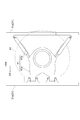
- Fig. 1 is a schematic side view of an articulated bus.
- the articulated bus 1 of the present embodiment includes a front vehicle 2, a rear vehicle 3, a articulated portion 4, and a hybrid system 5.
- the front vehicle 2 is disposed on the front side of the articulated bus 1 in the vehicle front-rear direction.
- the front vehicle 2 is a driven vehicle on which an engine that drives the articulated bus 1 is not mounted.
- the front vehicle 2 has a low floor like a non-step bus. For this reason, the front vehicle 2 is not provided with a step for getting on and off.
- the front vehicle 2 is attached with a front wheel 23a located on the front side in the vehicle front-rear direction and a first rear wheel 23b located on the rear side in the vehicle front-rear direction with respect to the front wheel 23a.
- the front wheels 23a are steering wheels connected to a steering mechanism.
- the front wheel 23a and the first rear wheel 23b are driven wheels that are not rotationally driven.
- the front vehicle 2 includes a front chassis frame 21 and a front vehicle body 22.
- the front chassis frame 21 is composed of a plurality of skeleton members.
- the front chassis frame 21 includes at least a laterally extending portion 21a (see FIG. 2) extending in the vehicle width direction at the rear end portion in the vehicle front-rear direction.
- the laterally extending portion 21a is a member connected to the articulated portion 4 and is also called a bulkhead.
- the front vehicle body 22 is connected to the front chassis frame 21 to form a passenger compartment.
- a front vehicle air conditioner unit 25 and an HV (Hybrid Vehicle) battery 52 described later are disposed on the roof 24 of the front body 22 .
- the front vehicle air conditioner unit 25 includes an evaporator (not shown) that air-conditions the passenger compartment of the front vehicle 2.
- the front vehicle air conditioner unit 25 (particularly an evaporator) is disposed between the front wheel 23a and the first rear wheel 23b in the vehicle longitudinal direction.
- a passage opening (not shown) is formed at the rear end of the front vehicle body 22 for a passenger to travel between the front vehicle 2 and the rear vehicle 3.
- the rear vehicle 3 is disposed on the rear side in the vehicle front-rear direction of the articulated bus 1 and behind the front vehicle 2 in the vehicle front-rear direction.
- the rear vehicle 3 is a drive vehicle in which an engine E / G that drives the articulated bus 1 is mounted at a rear end portion in the vehicle front-rear direction.
- An alternator 36 that generates electric power by rotational driving of the engine E / G is mounted on the rear end of the rear vehicle 3 in the vehicle longitudinal direction.
- the rear vehicle 3 is lowered like a non-step bus. For this reason, the rear vehicle 3 is not provided with a step for getting on and off.
- the rear vehicle 3 is attached with a second rear wheel 33 located at the center in the vehicle longitudinal direction.
- the second rear wheel 33 is a drive wheel that is driven to rotate by the rotation of the engine E / G to drive the articulated bus 1.
- the second rear wheel 33 is disposed in front of the engine E / G in the vehicle longitudinal direction.
- the rear vehicle 3 includes a rear chassis frame 31 and a rear vehicle body 32.
- the rear chassis frame 31 is composed of a plurality of skeleton members.
- the rear chassis frame 31 includes at least a first laterally extending portion 31a (see FIG. 2) extending in the vehicle width direction at the front end portion in the vehicle front-rear direction.
- the first laterally extending portion 31a is a member connected to the articulating portion 4 and is also called a bulkhead.
- the rear vehicle body 32 is connected to the rear chassis frame 31 to form a passenger compartment.
- a rear vehicle air conditioner unit 35 is disposed on the roof 34 of the rear vehicle body 32.
- the rear vehicle air conditioner unit 35 includes an evaporator (not shown) that air-conditions the passenger compartment of the rear vehicle 3.
- the rear vehicle air conditioner unit 35 (particularly an evaporator) is disposed at a position between the front end of the rear vehicle 3 and the second rear wheel 33 in the vehicle front-rear direction.
- a passage opening (not shown) is formed at the front end of the rear vehicle body 32 for a passenger to move between the front vehicle 2 and the rear vehicle 3.
- FIG. 2 is a schematic plan view showing the articulated portion.
- 3 is a cross-sectional view of the joint portion taken along line III-III shown in FIG.
- the articulating portion 4 articulates the front chassis frame 21 and the rear chassis frame 31 between the front vehicle 2 and the rear vehicle 3 so as to be swingable.
- the articulated portion 4 includes an articulated mechanism portion 41, a passage portion 42, and a hood 43.
- the articulation mechanism portion 41 includes a front connection portion 41a connected to the laterally extending portion 21a of the front chassis frame 21 and a rear side connection portion 41b connected to the first laterally extending portion 31a of the rear chassis frame 31.
- the front connection portion 41a and the rear connection portion 41b are connected between the front vehicle 2 and the rear vehicle 3 so as to be swingable about an axis extending in the vehicle vertical direction.
- the articulation mechanism 41 does not connect the front chassis frame 21 and the rear chassis frame 31 easily and detachably like a trailer (towing vehicle), but is connected to the front chassis frame 21 by fastening bolts.
- the rear chassis frame 31 is detachably connected. However, when there are special circumstances such as when maintenance is performed, the front chassis frame 21 and the rear chassis frame 31 can be separated by removing the bolts.
- the passage portion 42 is bridged between the front vehicle 2 and the rear vehicle 3 and placed on the articulation mechanism portion 41.
- the hood 43 is attached to the front vehicle 2 and the rear vehicle 3 to cover the articulation mechanism 41 and the passage 42.
- the hood 43 has a double structure of an outer lining 43a and an inner lining 43b, and a space A is formed between the outer lining 43a and the inner lining 43b.
- the outer cover 43 a forms the outer shape of the hood 43.
- the lining 43 b forms a passage space B that communicates with the passage opening of the front vehicle 2 and the passage opening of the rear vehicle 3 together with the passage portion 42.
- the hybrid system 5 includes a motor generator 51 and an HV battery 52.
- the motor generator 51 is a motor generator that functions as an electric motor and a generator. That is, when the motor generator 51 functions as a generator, it converts the kinetic energy of the rotating engine E / G into electric energy and charges the HV battery 52. On the other hand, when the motor generator 51 functions as an electric motor, the motor generator 51 rotates by the electric energy charged in the HV battery 52 and rotationally drives the second rear wheel 33. For this reason, the motor generator 51 is disposed at the rear end of the rear vehicle 3 in the vicinity of the engine E / G and the second rear wheel 33.
- the HV battery 52 is a battery dedicated to the hybrid system 5.
- the HV battery 52 stores the electric energy generated by the motor generator 51 and supplies the electric energy to the motor generator 51.
- the HV battery 52 is a module composed of a plurality of cells, and its weight is, for example, about 500 kg.
- the HV battery 52 is disposed on the roof 24 of the front vehicle 2. Specifically, the HV battery 52 is disposed at the same position as the axle of the front wheel 23a in the vehicle longitudinal direction.
- the HV battery 52 is mounted on the hybrid unit 53.
- a PCU inverter 54 that performs conversion between high-voltage direct current and alternating current, and a battery computer (not shown) that manages the SOC (State of Charge) to an appropriate value
- a cooling fan (not shown) that sends cooling air to the HV battery 52, a system main relay (not shown) that cuts off / shuts off the power supply of the high voltage circuit, and the like are mounted.
- the total weight of the hybrid unit 53 is about 700 kg, for example.
- FIG. 4 is a schematic cross-sectional view of the vicinity of the articulated portion.
- the articulated bus 1 includes an upper low-voltage electric wire 61, a lower low-voltage electric wire 62, and a high-voltage electric wire 63.
- the lower low voltage electric wire 62 is a power supply electric wire connected to the alternator 36.
- the lower low-voltage electric wire 62 is wired near the floor inside the front vehicle 2 and the rear vehicle 3 and is connected to each device of the articulated bus 1 excluding the HV battery 52.
- Devices connected to the lower low voltage electric wire 62 are a low voltage battery (24V), a heater unit, a push button, and the like.
- the lower low-voltage electric wire 62 includes a first lower low-voltage electric wire portion 62a, a second lower low-voltage electric wire portion 62b, and a third lower low-voltage electric wire portion 62c.
- the first lower side low voltage electric wire 62a is connected to the alternator 36 and wired near the floor inside the rear vehicle 3.
- the first lower low-voltage electric wire portion 62a extends from the alternator 36 to the vicinity of the floor around the front of the engine E / G at the rear end portion of the rear vehicle 3.
- the second lower low-voltage electric wire portion 62b is wired near the floor inside the front vehicle 2.
- the third lower low-voltage electric wire portion 62c is wired inside the hood 43 and connects the first lower low-voltage electric wire portion 62a and the second lower low-voltage electric wire portion 62b.
- the third lower low-voltage electric wire portion 62c is accommodated in the space A1 (see FIG. 3), similarly to the third upper low-voltage electric wire portion 61c.
- the upper low-voltage wire 61 is a control system (signal system) wire connected to a junction block (not shown).
- the junction block is disposed above the engine E / G and is supplied with power from the low voltage battery (24V) via the lower low voltage electric wire 62.
- the upper low-voltage electric wire 61 is wired near the ceiling inside the front vehicle 2 and the rear vehicle 3, and is connected to each device of the articulated bus 1 excluding the HV battery 52.
- a device connected to the upper low-voltage electric wire 61 is a chassis electrical component such as a computer or a fuse. Specifically, they are HV / ECU, engine ECU, ABS, vehicle height adjusting device, transmission and the like.
- the upper low-voltage wire 61 includes a first upper low-voltage wire portion 61a (first low-voltage wire portion), a second upper low-voltage wire portion 61b (second low-voltage wire portion), and a third upper low-voltage wire portion 61c (third low-voltage wire portion). Part).
- the first upper low-voltage electric wire 61a is connected to the junction block and wired near the ceiling inside the rear vehicle 3.
- the second upper low-voltage electric wire portion 61 b is wired near the ceiling inside the front vehicle 2.
- the third upper low-voltage electric wire 61c is wired inside the hood 43 and connects the first upper low-voltage electric wire 61a and the second upper low-voltage electric wire 61b.
- the first upper low-voltage electric wire portion 61a and the second upper low-voltage electric wire portion 61b are accommodated in a ceiling space (not shown) of the rear vehicle 3 and the front vehicle 2, respectively.
- the ceiling space is a space that is located above the passenger compartment and is isolated from the passenger compartment.
- the third upper low-voltage electric wire 61c is accommodated in a space A1 (see FIG. 3) on the side of the passage space B in the space A between the outer lining 43a and the inner lining 43b of the hood 43.
- the high voltage electric wire 63 is an electric wire connected to the motor generator 51, and a higher voltage current flows than the upper low voltage electric wire 61 and the lower low voltage electric wire 62. For example, a current of 600 V flows through the high-voltage wire 63, and a current of 24 V flows through the upper low-voltage wire 61 and the lower low-voltage wire 62.
- the high-voltage electric wire 63 is wired on the roof 24 of the front vehicle 2 and the roof 34 of the rear vehicle 3, and is connected to the HV battery 52 through the PCU inverter 54.
- the high voltage electric wire 63 includes a first high voltage electric wire portion 63a, a second high voltage electric wire portion 63b, and a third high voltage electric wire portion 63c.
- the first high voltage electric wire portion 63 a is connected to the motor generator 51 and wired on the roof 34 of the rear vehicle 3.
- the first high-voltage electric wire portion 63 a extends from the motor generator 51 to the top of the roof 34 of the rear vehicle 3 at the rear end portion of the rear vehicle 3.
- a cover (not shown) that covers the first high-voltage electric wire portion 63a is attached. Further, the first high-voltage electric wire portion 63 a enters the inside of the rear vehicle 3 from the top of the roof 34 of the rear vehicle 3 at the front end portion of the rear vehicle 3.
- both the first upper low-voltage electric wire portion 61 a and the first high-voltage electric wire portion 63 a are accommodated in the ceiling space of the rear vehicle 3.
- the first upper low-voltage electric wire portion 61a and the first high-voltage electric wire portion 63a may be affected by each other's noise by being arranged at positions close to each other. Therefore, at the front end portion of the rear vehicle 3, the first shielding portion 71 is disposed between the first upper low-voltage electric wire portion 61a and the first high-voltage electric wire portion 63a.
- the first shielding part 71 is a metal member that shields the first upper low-voltage electric wire part 61a and the first high-voltage electric wire part 63a.
- a thin metal plate can be used, for example.
- both the first upper low-voltage electric wire portion 61a and the first high-voltage electric wire portion 63a are arranged inside the rear vehicle body 32, but at this position, the first upper low-voltage electric wire portion 61a. Can be sufficiently separated from the first high-voltage electric wire portion 63a so as not to be affected by noise, so that a shielding portion is not disposed between the first upper low-voltage electric wire portion 61a and the first high-voltage electric wire portion 63a. Also good.
- the second high voltage electric wire portion 63 b is wired on the roof 24 of the front vehicle 2 and connected to the HV battery 52 via the PCU inverter 54.
- a cover (not shown) that covers the second high-voltage electric wire portion 63b is attached.
- the second high voltage electric wire portion 63 b enters the inside of the front vehicle 2 from the top of the roof 24 of the front vehicle 2 at the rear end portion of the front vehicle 2. That is, at the rear end portion of the front vehicle 2, both the second upper low-voltage electric wire portion 61 b and the second high-voltage electric wire portion 63 b are accommodated in the ceiling space of the front vehicle 2. For this reason, at the rear end portion of the front vehicle 2, the second upper low-voltage electric wire portion 61b and the second high-voltage electric wire portion 63b may be affected by each other's noise by being arranged at positions close to each other. is there.
- the second shielding portion 72 is disposed between the second upper low-voltage electric wire portion 61b and the second high-voltage electric wire portion 63b.
- the second shielding portion 72 is a metal member that shields the second upper low-voltage electric wire portion 61b and the second high-voltage electric wire portion 63b.
- a thin metal plate can be used, for example.
- the third high-voltage electric wire portion 63c is wired inside the hood 43 and connects the first high-voltage electric wire portion 63a and the second high-voltage electric wire portion 63b.
- the third high-voltage electric wire portion 63c includes a first high-voltage electric wire portion 63a at the front end of the rear vehicle 3 that has entered the inside of the rear vehicle 3 and a front vehicle 2 that has entered the inside of the front vehicle 2.
- the second high-voltage electric wire portion 63b at the rear end is connected.
- the third high-voltage electric wire portion 63c is accommodated in a space A2 (see FIG. 3) behind the ceiling, in the space A between the outer lining 43a and the inner lining 43b of the hood 43.
- the third upper low-voltage electric wire portion 61c and the third lower low-voltage electric wire portion 62c can be sufficiently separated from the third high-voltage electric wire portion 63c so as not to be affected by noise. It is not necessary to arrange a shielding part between the low voltage electric wire part 61c and the third lower low voltage electric cable part 62c and the third high voltage electric cable part 63c.
- the HV battery 52 is disposed on the roof 24 of the front vehicle 2, and therefore the HV battery 52 is disposed on the roof 34 of the rear vehicle 3.
- the weight ratio of the front vehicle 2 to the rear vehicle 3 is increased. Accordingly, it is possible to suppress a decrease in steering stability due to insufficient axial weight of the front wheel 23a which is a steered wheel.
- the position of the center of gravity of the rear vehicle 3 is lowered as compared with the case where the HV battery 52 is disposed on the roof 34 of the rear vehicle 3. Thereby, since the maximum stable inclination angle (turning angle) of the rear vehicle 3 is reduced, an increase in weight and an increase in cost of the rear vehicle 3 can be suppressed.
- the HV battery 52 and the axle of the front wheel 23a that is the steering wheel are arranged at the same position in the vehicle front-rear direction. Stability is improved.
- the high voltage electric wire 63 is wired on the roof 24 of the front vehicle 2 and the roof 34 of the rear vehicle 3 to which the cover can be easily attached, thereby extending the life of the high voltage electric wire 63.
- the hood 43 is bent while expanding and contracting as the rear vehicle 3 swings with respect to the front vehicle 2, so it is difficult to attach a cover to the outside of the hood 43. Therefore, between the rear vehicle 3 and the front vehicle 2, the life of the high voltage electric wire 63 can be extended by wiring the high voltage electric wire 63 inside the hood 43.
- the upper low-voltage electric wire 61 and the high-voltage electric wire 63 are wired inside the rear vehicle 3 and the front vehicle 2 at the front end portion of the rear vehicle 3 and the rear end portion of the front vehicle 2,
- the electric wires 63 may be affected by each other's noise. Therefore, in the articulated bus 1, the metal first shielding portion 71 and the second shielding are provided between the upper low-voltage electric wire 61 and the high-voltage electric wire 63 at the front end portion of the rear vehicle 3 and the rear end portion of the front vehicle 2.
- positioning the part 72 it can suppress that the upper side low voltage electric wire 61 and the high voltage electric wire 63 receive the influence of a mutual noise.
- the HV battery may be arranged at a position different from the front wheel axle in the vehicle longitudinal direction.
- the third high-voltage electric wire may be wired outside the hood (for example, on the hood) in the same manner as the first high-voltage electric wire and the second high-voltage electric wire.
- the PCU inverter 54 may be separated from the hybrid unit 53 and transferred to another location. For example, it may be moved near the motor generator 51.
- SYMBOLS 1 ... Articulated bus, 2 ... Front vehicle, 3 ... Rear vehicle, 4 ... Articulated part, 5 ... Hybrid system, 21 ... Front chassis frame, 21a ... Lateral extension part, 22 ... Front vehicle body, 23a ... Front wheel , 23b ... first rear wheel, 24 ... roof, 25 ... front vehicle air conditioner unit, 31 ... rear chassis frame, 31a ... first lateral extension, 32 ... rear body, 33 ... second rear wheel, 34 ... roof , 35 ... rear vehicle air conditioner unit, 36 ... alternator, 41 ... articulation mechanism, 41a ... front side connection part, 41b ... rear side connection part, 42 ... passage part, 43 ... hood, 43a ...
Abstract
An articulated bus is provided with: a front vehicle having steering wheels and also having rear wheels located behind the steering wheels in the front-rear direction of the vehicle; a rear vehicle disposed behind the front vehicle in the front-rear direction of the vehicle and having an engine mounted thereon; an articulation section for connecting the front vehicle and the rear vehicle so that the front vehicle and the rear vehicle can pivot relative to each other; a hybrid system having a motor generator functioning as a motor and as a generator, the hybrid system further having an HV battery for storing electric energy which is generated by the motor generator and supplying the electric energy to the motor generator. The HV battery is disposed on the roof of the front vehicle.
Description
本発明は、前部車両と後部車両とが揺動可能に連節された連節バスに関する。
The present invention relates to an articulated bus in which a front vehicle and a rear vehicle are articulated in a swingable manner.
日本では、1985年のつくば万博において、前部車両と後部車両とを連節した連節バスが導入された。連節バスは、前部車両の後面と後部車両の前面とに開口を設けて、前部車両と後部車両との間で乗員が行き来できるようにしたバスである。この連節バスは、前部車両が後部車両を牽引する牽引(プーラー)式連節バスである。牽引式連節バスは、前部車両の中央床下にエンジンが配置されるため、床面を高くして乗降口に2段のステップを備える2ステップバスとなる。
In Japan, an articulated bus connecting the front and rear vehicles was introduced at the 1985 Tsukuba Expo. The articulated bus is a bus in which openings are provided on the rear surface of the front vehicle and the front surface of the rear vehicle so that passengers can move between the front vehicle and the rear vehicle. This articulated bus is a towing (puller) articulated bus in which a front vehicle pulls a rear vehicle. Since the engine is disposed under the center floor of the front vehicle, the towed articulated bus becomes a two-step bus having a two-step step at the entrance and exit with the floor surface raised.
近年、乗降性の改善を目的として、床を低くしてステップを無くしたノンステップの低床バスが採用されるようになってきた。低床バスでは、エンジンを車両後端部に配置することで、低床化及びノンステップ化を実現している。このような時代の潮流に鑑みると、連節バスにおいても、低床化及びノンステップ化が強く求められると考えられる。そこで、エンジンを後部車両の後端部に配置して、後部車両で前部車両を押すプッシャー式連節バスにすることで、連節バスを低床化及びノンステップ化することが考えられる。
In recent years, non-step low-floor buses have been adopted in which the floor is lowered and steps are eliminated for the purpose of improving ease of getting on and off. In the low-floor bus, the engine is disposed at the rear end of the vehicle, thereby realizing a low floor and a non-step. In view of the trend of such times, it is considered that low flooring and non-stepping are strongly demanded even in articulated buses. Therefore, it is conceivable to lower the floor of the articulated bus and make it non-stepped by arranging the engine at the rear end of the rear vehicle and using a pusher-type articulated bus that pushes the front vehicle with the rear vehicle.
また、低燃費化および低排出ガス化を目的として、エンジンと電動発電機(モータジェネレータ)の二種類を駆動源とするハイブリッドシステムが採用されるようになってきた(例えば、特許文献1参照)。ハイブリッドシステムでは、電動発電機は、回転するエンジンの運動エネルギーを電気エネルギーに変換することでHVバッテリを充電するとともに、HVバッテリに充電された電気エネルギーにより回転して車両を駆動する。
Further, for the purpose of reducing fuel consumption and reducing exhaust gas, a hybrid system using two types of driving sources of an engine and a motor generator (motor generator) has been adopted (see, for example, Patent Document 1). . In the hybrid system, the motor generator charges the HV battery by converting the kinetic energy of the rotating engine into electric energy, and rotates the electric energy charged in the HV battery to drive the vehicle.
このようなハイブリッドシステムをプッシャー式の連節バスに搭載する場合、電動発電機は、エンジンと同様に後部車両の後端部に配置される。また、電動発電機とHVバッテリとは高圧電線により接続されるため、電動発電機とHVバッテリとの距離を近づけることが好ましい。このため、HVバッテリは、後部車両の屋根上に配置される。
When such a hybrid system is mounted on a pusher-type articulated bus, the motor generator is arranged at the rear end of the rear vehicle in the same manner as the engine. Moreover, since the motor generator and the HV battery are connected by a high-voltage electric wire, it is preferable to make the distance between the motor generator and the HV battery closer. For this reason, the HV battery is arranged on the roof of the rear vehicle.
しかしながら、ハイブリッドシステムの電動発電機及びHVバッテリは、連節バスの重量物となる。このため、電動発電機を後部車両の後端部に配置し、HVバッテリを後部車両の屋根上に配置すると、後部車両に対して前部車両が軽くなり過ぎてしまい、操舵輪の軸重が不足する。その結果、操縦安定性が低下し、更には、タイヤの偏摩耗および後部車両のサスペンションのエアベローズの劣化が大きくなる。
However, the motor generator and the HV battery of the hybrid system are heavy items of articulated buses. For this reason, when the motor generator is disposed at the rear end of the rear vehicle and the HV battery is disposed on the roof of the rear vehicle, the front vehicle becomes too light with respect to the rear vehicle, and the axle weight of the steered wheels is increased. Run short. As a result, steering stability is lowered, and further, uneven wear of tires and deterioration of the air bellows of the rear vehicle suspension are increased.
しかも、各車両の屋根上にはエアコンユニット(エバポレータ)も配置される。すると、重心位置が高くなるため、最大安定傾斜角度(転角)を確保するために、トレッド拡大など車両の大幅な変更が必要になる。その結果、車両重量及び製造コストが増加する。
Moreover, an air conditioner unit (evaporator) is also arranged on the roof of each vehicle. Then, since the position of the center of gravity becomes high, a large change in the vehicle such as a tread expansion is necessary to secure the maximum stable inclination angle (turning angle). As a result, vehicle weight and manufacturing costs increase.
そこで、本発明の一側面は、操縦安定性の低下、及び後部車両の重量増加及びコストアップを抑制できる連節バスを提供することを目的とする。
Accordingly, an object of the present invention is to provide an articulated bus capable of suppressing a reduction in steering stability, an increase in weight of a rear vehicle, and an increase in cost.
本発明者は、上記目的を達成するべく鋭意研究を行った結果、高圧電線を短くした方が良いとの当業者の技術常識に反して、高圧電線を長くすることで、操縦安定性の低下、及び後部車両の重量増加及びコストアップを抑制できるとの知見に至った。
As a result of diligent research to achieve the above object, the present inventor has found that it is better to shorten the high-voltage electric wire, contrary to the technical common knowledge of those skilled in the art, the longer the high-voltage electric wire, the lower the steering stability. As a result, the inventors have found that the increase in weight and cost of rear vehicles can be suppressed.
すなわち、本発明の一側面に係る連節バスは、操舵輪と、操舵輪よりも車両前後方向後方に配置された後輪と、を有する前部車両と、前部車両の車両前後方向後方に配置されてエンジンが搭載された後部車両と、前部車両と後部車両とを揺動可能に連節する連節部と、電動機及び発電機として機能する電動発電機と、電動発電機により発電された電気エネルギーを蓄電するとともに電動発電機に電気エネルギーを供給するHVバッテリと、を有するハイブリッドシステムと、を備え、HVバッテリは、前部車両の屋根上に配置される。
That is, the articulated bus according to one aspect of the present invention includes a front vehicle having a steering wheel and a rear wheel disposed rearward in the vehicle front-rear direction with respect to the steering wheel, and a vehicle front-rear direction rear of the front vehicle. A rear vehicle that is disposed and mounted with an engine, a joint that articulates the front vehicle and the rear vehicle, a motor generator that functions as a motor and a generator, and a motor generator that generates power. And a hybrid system having an HV battery for storing electric energy and supplying electric energy to the motor generator. The HV battery is disposed on the roof of the front vehicle.
本発明の一側面に係る連節バスでは、HVバッテリが前部車両の屋根上に配置されるため、HVバッテリが後部車両の屋根上に配置される場合に比べて、後部車両に対する前部車両の重量割合が大きくなる。これにより、操舵輪の軸重不足による操縦安定性の低下を抑制することができる。しかも、HVバッテリが後部車両の屋根上に配置される場合に比べて、後部車両の重心位置が下がる。これにより、後部車両の最大安定傾斜角度(転角)が小さくなるため、後部車両の重量増加及びコストアップを抑制することができる。
In the articulated bus according to one aspect of the present invention, since the HV battery is disposed on the roof of the front vehicle, the front vehicle for the rear vehicle is compared with the case where the HV battery is disposed on the roof of the rear vehicle. The weight ratio of increases. As a result, it is possible to suppress a decrease in steering stability due to insufficient axle load of the steered wheels. Moreover, the position of the center of gravity of the rear vehicle is lowered as compared with the case where the HV battery is disposed on the roof of the rear vehicle. Thereby, since the maximum stable inclination angle (turning angle) of the rear vehicle is reduced, it is possible to suppress an increase in weight and cost of the rear vehicle.
また、HVバッテリは、車両前後方向において操舵輪の車軸と同じ位置に配置されてもよい。
Further, the HV battery may be disposed at the same position as the axle of the steering wheel in the vehicle front-rear direction.
また、低圧電線と、低圧電線よりも高圧の電流が流れて電動発電機及びHVバッテリに接続される高圧電線と、を更に備え、連節部は、前部車両と後部車両とを連通する通路空間を形成する幌を備え、低圧電線は、後部車両の内側に配線される第一低圧電線部と、前部車両の内側に配線される第二低圧電線部と、幌の内側に配線されて、第一低圧電線部と第二低圧電線部とを接続する第三低圧電線部と、を備え、高圧電線は、後部車両の屋根上に配線されて、後部車両の前端部において後部車両の屋根上から後部車両の内側に入る第一高圧電線部と、前部車両の屋根上に配線されて、前部車両の後端部において前部車両の屋根上から前部車両の内側に入る第二高圧電線部と、幌の内側に配線されて、第一高圧電線部と第二高圧電線部とを接続する第三高圧電線部と、を備えてもよい。
And a high-voltage electric wire connected to the motor generator and the HV battery through which a higher-voltage current flows than the low-voltage electric wire, and the joint portion is a passage that communicates the front vehicle and the rear vehicle. A hood forming a space is provided, and the low-voltage electric wire is wired inside the hood, a first low-voltage electric wire portion wired inside the rear vehicle, a second low-voltage electric wire portion wired inside the front vehicle, and the hood. A third low voltage electric wire portion connecting the first low voltage electric wire portion and the second low voltage electric wire portion, the high voltage electric wire being wired on the roof of the rear vehicle, and the roof of the rear vehicle at the front end of the rear vehicle A first high-voltage electric wire portion that enters the inside of the rear vehicle from above, and a second wire that is wired on the roof of the front vehicle and enters the inside of the front vehicle from the roof of the front vehicle at the rear end portion of the front vehicle It is wired inside the hood and the inside of the hood to connect the first high-voltage cable part and the second high-voltage cable part. A third high-voltage cable section that may be provided.
また、後部車両の前端部における第一低圧電線部と第一高圧電線部との間に配置されて、第一低圧電線部と第一高圧電線部とを遮蔽する金属製の第一遮蔽部と、前部車両の後端部における第二低圧電線部と第二高圧電線部との間に配置されて、第二低圧電線部と第二高圧電線部とを遮蔽する金属製の第二遮蔽部と、を備えてもよい。
A first shielding portion made of metal that is disposed between the first low-voltage electric wire portion and the first high-voltage electric wire portion at the front end of the rear vehicle and shields the first low-voltage electric wire portion and the first high-voltage electric wire portion; The second shielding part made of metal which is disposed between the second low voltage electric wire part and the second high voltage electric cable part at the rear end of the front vehicle and shields the second low voltage electric cable part and the second high voltage electric cable part And may be provided.
本発明の一側面によれば、操縦安定性の低下、及び後部車両の重量増加及びコストアップを抑制できる。
According to one aspect of the present invention, it is possible to suppress a decrease in steering stability, an increase in weight of the rear vehicle, and an increase in cost.
以下、実施形態に係る連節バスについて、図面を参照して詳細に説明する。なお、以下の説明において同一又は相当要素には同一符号を付し、重複する説明を省略する。また、以下の説明では、車両前後方向における前及び後を単に前及び後ともいい、車両上下方向における上及び下を単に上及び下ともいう。
Hereinafter, the articulated bus according to the embodiment will be described in detail with reference to the drawings. In the following description, the same or equivalent elements will be denoted by the same reference numerals, and redundant description will be omitted. In the following description, front and rear in the vehicle front-rear direction are also simply referred to as front and rear, and upper and lower in the vehicle vertical direction are also simply referred to as upper and lower.
図1は、連節バスの概略側面図である。図1に示すように、本実施形態の連節バス1は、前部車両2と、後部車両3と、連節部4と、ハイブリッドシステム5と、を備える。
Fig. 1 is a schematic side view of an articulated bus. As shown in FIG. 1, the articulated bus 1 of the present embodiment includes a front vehicle 2, a rear vehicle 3, a articulated portion 4, and a hybrid system 5.
前部車両2は、連節バス1の車両前後方向前側に配置される。前部車両2は、連節バス1を駆動するエンジンが搭載されない従動車両である。前部車両2は、ノンステップバスのように低床化されている。このため、前部車両2には、乗降するためのステップが設けられない。
The front vehicle 2 is disposed on the front side of the articulated bus 1 in the vehicle front-rear direction. The front vehicle 2 is a driven vehicle on which an engine that drives the articulated bus 1 is not mounted. The front vehicle 2 has a low floor like a non-step bus. For this reason, the front vehicle 2 is not provided with a step for getting on and off.
前部車両2には、車両前後方向前側に位置する前輪23aと、前輪23aよりも車両前後方向後方に位置する第一後輪23bと、が取り付けられる。前輪23aは、操舵機構に連結された操舵輪である。前輪23a及び第一後輪23bは、回転駆動されない従動輪である。前部車両2は、前部シャシフレーム21と、前部車体22と、を備える。
The front vehicle 2 is attached with a front wheel 23a located on the front side in the vehicle front-rear direction and a first rear wheel 23b located on the rear side in the vehicle front-rear direction with respect to the front wheel 23a. The front wheels 23a are steering wheels connected to a steering mechanism. The front wheel 23a and the first rear wheel 23b are driven wheels that are not rotationally driven. The front vehicle 2 includes a front chassis frame 21 and a front vehicle body 22.
前部シャシフレーム21は、複数の骨格部材により構成される。前部シャシフレーム21は、少なくとも、車両前後方向後端部において車両幅方向に延びる横延部21a(図2参照)を備える。横延部21aは、連節部4と接続される部材であり、バルクヘッドとも呼ばれる。
The front chassis frame 21 is composed of a plurality of skeleton members. The front chassis frame 21 includes at least a laterally extending portion 21a (see FIG. 2) extending in the vehicle width direction at the rear end portion in the vehicle front-rear direction. The laterally extending portion 21a is a member connected to the articulated portion 4 and is also called a bulkhead.
前部車体22は、前部シャシフレーム21に接続されて、車室を形成する。前部車体22の屋根24上には、前部車両用エアコンユニット25及び後述するHV(Hybrid Vehicle)バッテリ52が配置される。前部車両用エアコンユニット25は、前部車両2の車室内の空調を行うエバポレータ(不図示)を備える。前部車両用エアコンユニット25(特に、エバポレータ)は、車両前後方向における前輪23aと第一後輪23bとの間に配置される。前部車体22の後端部には、乗客が前部車両2と後部車両3との間で行き来するための通路用開口(不図示)が形成される。
The front vehicle body 22 is connected to the front chassis frame 21 to form a passenger compartment. On the roof 24 of the front body 22, a front vehicle air conditioner unit 25 and an HV (Hybrid Vehicle) battery 52 described later are disposed. The front vehicle air conditioner unit 25 includes an evaporator (not shown) that air-conditions the passenger compartment of the front vehicle 2. The front vehicle air conditioner unit 25 (particularly an evaporator) is disposed between the front wheel 23a and the first rear wheel 23b in the vehicle longitudinal direction. A passage opening (not shown) is formed at the rear end of the front vehicle body 22 for a passenger to travel between the front vehicle 2 and the rear vehicle 3.
後部車両3は、連節バス1の車両前後方向後側であって、前部車両2の車両前後方向後方に配置される。後部車両3は、連節バス1を駆動するエンジンE/Gが車両前後方向後端部に搭載された駆動車両である。後部車両3の車両前後方向後端部には、エンジンE/Gの回転駆動により発電するオルタネータ36が搭載されている。後部車両3は、ノンステップバスのように低床化されている。このため、後部車両3には、乗降するためのステップが設けられない。
The rear vehicle 3 is disposed on the rear side in the vehicle front-rear direction of the articulated bus 1 and behind the front vehicle 2 in the vehicle front-rear direction. The rear vehicle 3 is a drive vehicle in which an engine E / G that drives the articulated bus 1 is mounted at a rear end portion in the vehicle front-rear direction. An alternator 36 that generates electric power by rotational driving of the engine E / G is mounted on the rear end of the rear vehicle 3 in the vehicle longitudinal direction. The rear vehicle 3 is lowered like a non-step bus. For this reason, the rear vehicle 3 is not provided with a step for getting on and off.
後部車両3には、車両前後方向中央部に位置する第二後輪33が取り付けられる。第二後輪33は、エンジンE/Gの回転により回転駆動されて、連節バス1を駆動させる駆動輪である。第二後輪33は、車両前後方向においてエンジンE/Gよりも前方に配置される。後部車両3は、後部シャシフレーム31と、後部車体32と、を備える。
The rear vehicle 3 is attached with a second rear wheel 33 located at the center in the vehicle longitudinal direction. The second rear wheel 33 is a drive wheel that is driven to rotate by the rotation of the engine E / G to drive the articulated bus 1. The second rear wheel 33 is disposed in front of the engine E / G in the vehicle longitudinal direction. The rear vehicle 3 includes a rear chassis frame 31 and a rear vehicle body 32.
後部シャシフレーム31は、複数の骨格部材により構成される。後部シャシフレーム31は、少なくとも、車両前後方向前端部において車両幅方向に延びる第一横延部31a(図2参照)を備える。第一横延部31aは、連節部4と接続される部材であり、バルクヘッドとも呼ばれる。
The rear chassis frame 31 is composed of a plurality of skeleton members. The rear chassis frame 31 includes at least a first laterally extending portion 31a (see FIG. 2) extending in the vehicle width direction at the front end portion in the vehicle front-rear direction. The first laterally extending portion 31a is a member connected to the articulating portion 4 and is also called a bulkhead.
後部車体32は、後部シャシフレーム31に接続されて、車室を形成する。後部車体32の屋根34上には、後部車両用エアコンユニット35が配置される。後部車両用エアコンユニット35は、後部車両3の車室内の空調を行うエバポレータ(不図示)を備える。後部車両用エアコンユニット35(特に、エバポレータ)は、車両前後方向における後部車両3の前端と第二後輪33との間の位置に配置される。後部車体32の前端部には、乗客が前部車両2と後部車両3との間で行き来するための通路用開口(不図示)が形成される。
The rear vehicle body 32 is connected to the rear chassis frame 31 to form a passenger compartment. A rear vehicle air conditioner unit 35 is disposed on the roof 34 of the rear vehicle body 32. The rear vehicle air conditioner unit 35 includes an evaporator (not shown) that air-conditions the passenger compartment of the rear vehicle 3. The rear vehicle air conditioner unit 35 (particularly an evaporator) is disposed at a position between the front end of the rear vehicle 3 and the second rear wheel 33 in the vehicle front-rear direction. A passage opening (not shown) is formed at the front end of the rear vehicle body 32 for a passenger to move between the front vehicle 2 and the rear vehicle 3.
図2は、連節部を示す概略平面図である。図3は、図1に示すIII-III線における連節部の断面図である。図1~図3に示すように、連節部4は、前部車両2と後部車両3との間において前部シャシフレーム21と後部シャシフレーム31とを揺動可能に連節する。連節部4は、連節機構部41と、通路部42と、幌43と、を備える。
FIG. 2 is a schematic plan view showing the articulated portion. 3 is a cross-sectional view of the joint portion taken along line III-III shown in FIG. As shown in FIGS. 1 to 3, the articulating portion 4 articulates the front chassis frame 21 and the rear chassis frame 31 between the front vehicle 2 and the rear vehicle 3 so as to be swingable. The articulated portion 4 includes an articulated mechanism portion 41, a passage portion 42, and a hood 43.
連節機構部41は、前部シャシフレーム21の横延部21aに接続される前側接続部41aと、後部シャシフレーム31の第一横延部31aに接続される後側接続部41bと、を備える。前側接続部41aと後側接続部41bとは、前部車両2と後部車両3との間において、車両上下方向に延びる軸線を揺動中心として揺動可能に接続される。なお、連節機構部41は、トレーラー(牽引車)のように前部シャシフレーム21と後部シャシフレーム31とを容易に着脱可能に接続するのではなく、ボルトの締結により前部シャシフレーム21と後部シャシフレーム31とを着脱不能に接続する。但し、メンテナンスを行う場合等の特段の事情があるときは、ボルトを外すことにより前部シャシフレーム21と後部シャシフレーム31とを分離することが可能となる。
The articulation mechanism portion 41 includes a front connection portion 41a connected to the laterally extending portion 21a of the front chassis frame 21 and a rear side connection portion 41b connected to the first laterally extending portion 31a of the rear chassis frame 31. Prepare. The front connection portion 41a and the rear connection portion 41b are connected between the front vehicle 2 and the rear vehicle 3 so as to be swingable about an axis extending in the vehicle vertical direction. The articulation mechanism 41 does not connect the front chassis frame 21 and the rear chassis frame 31 easily and detachably like a trailer (towing vehicle), but is connected to the front chassis frame 21 by fastening bolts. The rear chassis frame 31 is detachably connected. However, when there are special circumstances such as when maintenance is performed, the front chassis frame 21 and the rear chassis frame 31 can be separated by removing the bolts.
通路部42は、前部車両2と後部車両3とに架け渡されて、連節機構部41に載置される。
The passage portion 42 is bridged between the front vehicle 2 and the rear vehicle 3 and placed on the articulation mechanism portion 41.
幌43は、前部車両2及び後部車両3に取り付けられて、連節機構部41及び通路部42を覆う。幌43は、外張43aと内張43bとの二重構造になっており、外張43aと内張43bとの間に空間Aが形成される。外張43aは、幌43の外形を形成する。内張43bは、通路部42とともに、前部車両2の通路用開口と後部車両3の通路用開口とに連通される通路空間Bを形成する。
The hood 43 is attached to the front vehicle 2 and the rear vehicle 3 to cover the articulation mechanism 41 and the passage 42. The hood 43 has a double structure of an outer lining 43a and an inner lining 43b, and a space A is formed between the outer lining 43a and the inner lining 43b. The outer cover 43 a forms the outer shape of the hood 43. The lining 43 b forms a passage space B that communicates with the passage opening of the front vehicle 2 and the passage opening of the rear vehicle 3 together with the passage portion 42.
ハイブリッドシステム5は、電動発電機51と、HVバッテリ52と、を備える。
The hybrid system 5 includes a motor generator 51 and an HV battery 52.
電動発電機51は、電動機及び発電機として機能するモータジェネレータである。つまり、電動発電機51は、発電機として機能する場合、回転するエンジンE/Gの運動エネルギーを電気エネルギーに変換して、HVバッテリ52を充電する。一方、電動発電機51は、電動機として機能する場合、HVバッテリ52に充電されている電気エネルギーにより回転して、第二後輪33を回転駆動する。このため、電動発電機51は、エンジンE/G及び第二後輪33の近傍である後部車両3の後端部に配置される。
The motor generator 51 is a motor generator that functions as an electric motor and a generator. That is, when the motor generator 51 functions as a generator, it converts the kinetic energy of the rotating engine E / G into electric energy and charges the HV battery 52. On the other hand, when the motor generator 51 functions as an electric motor, the motor generator 51 rotates by the electric energy charged in the HV battery 52 and rotationally drives the second rear wheel 33. For this reason, the motor generator 51 is disposed at the rear end of the rear vehicle 3 in the vicinity of the engine E / G and the second rear wheel 33.
HVバッテリ52は、ハイブリッドシステム5専用のバッテリである。HVバッテリ52は、電動発電機51により発電された電気エネルギーを蓄電するとともに、電動発電機51に電気エネルギーを供給する。HVバッテリ52は、複数のセルで構成されたモジュールであり、その重量は、例えば、500kg程度となる。HVバッテリ52は、前部車両2の屋根24上に配置される。具体的には、HVバッテリ52は、車両前後方向における前輪23aの車軸と同じ位置に配置される。
HV battery 52 is a battery dedicated to the hybrid system 5. The HV battery 52 stores the electric energy generated by the motor generator 51 and supplies the electric energy to the motor generator 51. The HV battery 52 is a module composed of a plurality of cells, and its weight is, for example, about 500 kg. The HV battery 52 is disposed on the roof 24 of the front vehicle 2. Specifically, the HV battery 52 is disposed at the same position as the axle of the front wheel 23a in the vehicle longitudinal direction.
HVバッテリ52は、ハイブリッドユニット53に搭載される。ハイブリッドユニット53には、HVバッテリ52の他に、高電圧の直流と交流との変換を行うPCUインバータ54、SOC(State of Charge:充電状態)を適切な値に管理するバッテリコンピュータ(不図示)、HVバッテリ52に冷却風を送る冷却ファン(不図示)、高電圧回路の電源の切断・遮断を行うシステムメインリレー(不図示)等が搭載される。ハイブリッドユニット53全体の重量は、例えば、700kg程度となる。
The HV battery 52 is mounted on the hybrid unit 53. In the hybrid unit 53, in addition to the HV battery 52, a PCU inverter 54 that performs conversion between high-voltage direct current and alternating current, and a battery computer (not shown) that manages the SOC (State of Charge) to an appropriate value A cooling fan (not shown) that sends cooling air to the HV battery 52, a system main relay (not shown) that cuts off / shuts off the power supply of the high voltage circuit, and the like are mounted. The total weight of the hybrid unit 53 is about 700 kg, for example.
図4は、連節部付近の概略断面図である。図1及び図4に示すように、連節バス1は、上側低圧電線61と、下側低圧電線62と、高圧電線63と、を備える。
FIG. 4 is a schematic cross-sectional view of the vicinity of the articulated portion. As shown in FIGS. 1 and 4, the articulated bus 1 includes an upper low-voltage electric wire 61, a lower low-voltage electric wire 62, and a high-voltage electric wire 63.
下側低圧電線62は、オルタネータ36に接続される電源系の電線である。下側低圧電線62は、前部車両2及び後部車両3の内側の床付近に配線されて、HVバッテリ52を除く連節バス1の各装置と接続される。下側低圧電線62に接続される装置は、低圧バッテリ(24V)、ヒータユニット、押しボタン等である。下側低圧電線62は、第一下側低圧電線部62aと、第二下側低圧電線部62bと、第三下側低圧電線部62cと、を備える。
The lower low voltage electric wire 62 is a power supply electric wire connected to the alternator 36. The lower low-voltage electric wire 62 is wired near the floor inside the front vehicle 2 and the rear vehicle 3 and is connected to each device of the articulated bus 1 excluding the HV battery 52. Devices connected to the lower low voltage electric wire 62 are a low voltage battery (24V), a heater unit, a push button, and the like. The lower low-voltage electric wire 62 includes a first lower low-voltage electric wire portion 62a, a second lower low-voltage electric wire portion 62b, and a third lower low-voltage electric wire portion 62c.
第一下側低圧電線部62aは、オルタネータ36に接続されて、後部車両3の内側の床付近に配線される。なお、第一下側低圧電線部62aは、後部車両3の後端部において、オルタネータ36からエンジンE/Gの前方を回って床付近まで延びる。第二下側低圧電線部62bは、前部車両2の内側の床付近に配線される。第三下側低圧電線部62cは、幌43の内側に配線されて、第一下側低圧電線部62aと第二下側低圧電線部62bとを接続する。第三下側低圧電線部62cは、第三上側低圧電線部61cと同様に、空間A1(図3参照)に収容される。
The first lower side low voltage electric wire 62a is connected to the alternator 36 and wired near the floor inside the rear vehicle 3. The first lower low-voltage electric wire portion 62a extends from the alternator 36 to the vicinity of the floor around the front of the engine E / G at the rear end portion of the rear vehicle 3. The second lower low-voltage electric wire portion 62b is wired near the floor inside the front vehicle 2. The third lower low-voltage electric wire portion 62c is wired inside the hood 43 and connects the first lower low-voltage electric wire portion 62a and the second lower low-voltage electric wire portion 62b. The third lower low-voltage electric wire portion 62c is accommodated in the space A1 (see FIG. 3), similarly to the third upper low-voltage electric wire portion 61c.
上側低圧電線61は、ジャンクションブロック(不図示)に接続される制御系(信号系)の電線である。ジャンクションブロックは、エンジンE/Gの上方に配置されており、下側低圧電線62を介して低圧バッテリ(24V)から給電される。上側低圧電線61は、前部車両2及び後部車両3の内側の天井付近に配線されて、HVバッテリ52を除く連節バス1の各装置と接続される。上側低圧電線61に接続される装置は、コンピュータ、ヒューズ類などのシャシ電装品である。具体的には、HV・ECU、エンジンECU、ABS、車高調整装置、トランスミッション等である。上側低圧電線61は、第一上側低圧電線部61a(第一低圧電線部)と、第二上側低圧電線部61b(第二低圧電線部)と、第三上側低圧電線部61c(第三低圧電線部)と、を備える。
The upper low-voltage wire 61 is a control system (signal system) wire connected to a junction block (not shown). The junction block is disposed above the engine E / G and is supplied with power from the low voltage battery (24V) via the lower low voltage electric wire 62. The upper low-voltage electric wire 61 is wired near the ceiling inside the front vehicle 2 and the rear vehicle 3, and is connected to each device of the articulated bus 1 excluding the HV battery 52. A device connected to the upper low-voltage electric wire 61 is a chassis electrical component such as a computer or a fuse. Specifically, they are HV / ECU, engine ECU, ABS, vehicle height adjusting device, transmission and the like. The upper low-voltage wire 61 includes a first upper low-voltage wire portion 61a (first low-voltage wire portion), a second upper low-voltage wire portion 61b (second low-voltage wire portion), and a third upper low-voltage wire portion 61c (third low-voltage wire portion). Part).
第一上側低圧電線部61aは、ジャンクションブロックに接続されて、後部車両3の内側の天井付近に配線される。第二上側低圧電線部61bは、前部車両2の内側の天井付近に配線される。第三上側低圧電線部61cは、幌43の内側に配線されて、第一上側低圧電線部61aと第二上側低圧電線部61bとを接続する。第一上側低圧電線部61a及び第二上側低圧電線部61bは、それぞれ後部車両3及び前部車両2の天井裏空間(不図示)に収容される。天井裏空間は、車室の上方に位置するとともに、車室から隔離される空間である。第三上側低圧電線部61cは、幌43の外張43aと内張43bとの間の空間Aのうち、通路空間B側方の空間A1(図3参照)に収容される。
The first upper low-voltage electric wire 61a is connected to the junction block and wired near the ceiling inside the rear vehicle 3. The second upper low-voltage electric wire portion 61 b is wired near the ceiling inside the front vehicle 2. The third upper low-voltage electric wire 61c is wired inside the hood 43 and connects the first upper low-voltage electric wire 61a and the second upper low-voltage electric wire 61b. The first upper low-voltage electric wire portion 61a and the second upper low-voltage electric wire portion 61b are accommodated in a ceiling space (not shown) of the rear vehicle 3 and the front vehicle 2, respectively. The ceiling space is a space that is located above the passenger compartment and is isolated from the passenger compartment. The third upper low-voltage electric wire 61c is accommodated in a space A1 (see FIG. 3) on the side of the passage space B in the space A between the outer lining 43a and the inner lining 43b of the hood 43.
高圧電線63は、電動発電機51に接続される電線であり、上側低圧電線61及び下側低圧電線62よりも高圧の電流が流れる。例えば、高圧電線63には600Vの電流が流れ、上側低圧電線61及び下側低圧電線62には24Vの電流が流れる。高圧電線63は、前部車両2の屋根24上及び後部車両3の屋根34上に配線されて、PCUインバータ54を経てHVバッテリ52に接続される。高圧電線63は、第一高圧電線部63aと、第二高圧電線部63bと、第三高圧電線部63cと、を備える。
The high voltage electric wire 63 is an electric wire connected to the motor generator 51, and a higher voltage current flows than the upper low voltage electric wire 61 and the lower low voltage electric wire 62. For example, a current of 600 V flows through the high-voltage wire 63, and a current of 24 V flows through the upper low-voltage wire 61 and the lower low-voltage wire 62. The high-voltage electric wire 63 is wired on the roof 24 of the front vehicle 2 and the roof 34 of the rear vehicle 3, and is connected to the HV battery 52 through the PCU inverter 54. The high voltage electric wire 63 includes a first high voltage electric wire portion 63a, a second high voltage electric wire portion 63b, and a third high voltage electric wire portion 63c.
第一高圧電線部63aは、電動発電機51に接続されて、後部車両3の屋根34上に配線される。なお、第一高圧電線部63aは、後部車両3の後端部において、電動発電機51から後部車両3の屋根34上まで延びる。後部車両3の屋根34上には、第一高圧電線部63aを覆うカバー(不図示)が取り付けられる。また、第一高圧電線部63aは、後部車両3の前端部において、後部車両3の屋根34上から後部車両3の内側に入る。つまり、後部車両3の前端部では、第一上側低圧電線部61a及び第一高圧電線部63aの双方が、後部車両3の天井裏空間に収容される。このため、後部車両3の前端部では、第一上側低圧電線部61a及び第一高圧電線部63aは、互いに近接した位置に配置されることで、互いのノイズの影響を受ける可能性がある。そこで、後部車両3の前端部では、第一上側低圧電線部61aと第一高圧電線部63aとの間に、第一遮蔽部71が配置される。第一遮蔽部71は、第一上側低圧電線部61aと第一高圧電線部63aとを遮蔽する金属製の部材である。第一遮蔽部71としては、例えば、薄い金属板を用いることができる。
The first high voltage electric wire portion 63 a is connected to the motor generator 51 and wired on the roof 34 of the rear vehicle 3. The first high-voltage electric wire portion 63 a extends from the motor generator 51 to the top of the roof 34 of the rear vehicle 3 at the rear end portion of the rear vehicle 3. On the roof 34 of the rear vehicle 3, a cover (not shown) that covers the first high-voltage electric wire portion 63a is attached. Further, the first high-voltage electric wire portion 63 a enters the inside of the rear vehicle 3 from the top of the roof 34 of the rear vehicle 3 at the front end portion of the rear vehicle 3. That is, at the front end portion of the rear vehicle 3, both the first upper low-voltage electric wire portion 61 a and the first high-voltage electric wire portion 63 a are accommodated in the ceiling space of the rear vehicle 3. For this reason, at the front end portion of the rear vehicle 3, the first upper low-voltage electric wire portion 61a and the first high-voltage electric wire portion 63a may be affected by each other's noise by being arranged at positions close to each other. Therefore, at the front end portion of the rear vehicle 3, the first shielding portion 71 is disposed between the first upper low-voltage electric wire portion 61a and the first high-voltage electric wire portion 63a. The first shielding part 71 is a metal member that shields the first upper low-voltage electric wire part 61a and the first high-voltage electric wire part 63a. As the 1st shielding part 71, a thin metal plate can be used, for example.
なお、後部車両3の後端部では、第一上側低圧電線部61a及び第一高圧電線部63aの双方が後部車体32の内側に配置されるが、当該位置では、第一上側低圧電線部61aは、第一高圧電線部63aからノイズの影響を受けない程度に十分に離すことができるため、第一上側低圧電線部61aと第一高圧電線部63aとの間に遮蔽部を配置しなくてもよい。
Note that, at the rear end of the rear vehicle 3, both the first upper low-voltage electric wire portion 61a and the first high-voltage electric wire portion 63a are arranged inside the rear vehicle body 32, but at this position, the first upper low-voltage electric wire portion 61a. Can be sufficiently separated from the first high-voltage electric wire portion 63a so as not to be affected by noise, so that a shielding portion is not disposed between the first upper low-voltage electric wire portion 61a and the first high-voltage electric wire portion 63a. Also good.
第二高圧電線部63bは、前部車両2の屋根24上に配線されて、PCUインバータ54を経てHVバッテリ52に接続される。前部車両2の屋根24上には、第二高圧電線部63bを覆うカバー(不図示)が取り付けられる。また、第二高圧電線部63bは、前部車両2の後端部において、前部車両2の屋根24上から前部車両2の内側に入る。つまり、前部車両2の後端部では、第二上側低圧電線部61b及び第二高圧電線部63bの双方が、前部車両2の天井裏空間に収容される。このため、前部車両2の後端部では、第二上側低圧電線部61b及び第二高圧電線部63bは、互いに近接した位置に配置されることで、互いのノイズの影響を受ける可能性がある。
The second high voltage electric wire portion 63 b is wired on the roof 24 of the front vehicle 2 and connected to the HV battery 52 via the PCU inverter 54. On the roof 24 of the front vehicle 2, a cover (not shown) that covers the second high-voltage electric wire portion 63b is attached. Further, the second high voltage electric wire portion 63 b enters the inside of the front vehicle 2 from the top of the roof 24 of the front vehicle 2 at the rear end portion of the front vehicle 2. That is, at the rear end portion of the front vehicle 2, both the second upper low-voltage electric wire portion 61 b and the second high-voltage electric wire portion 63 b are accommodated in the ceiling space of the front vehicle 2. For this reason, at the rear end portion of the front vehicle 2, the second upper low-voltage electric wire portion 61b and the second high-voltage electric wire portion 63b may be affected by each other's noise by being arranged at positions close to each other. is there.
そこで、前部車両2の後端部では、第二上側低圧電線部61bと第二高圧電線部63bとの間に、第二遮蔽部72が配置される。第二遮蔽部72は、第二上側低圧電線部61bと第二高圧電線部63bとを遮蔽する金属製の部材である。第二遮蔽部72としては、例えば、薄い金属板を用いることができる。
Therefore, at the rear end portion of the front vehicle 2, the second shielding portion 72 is disposed between the second upper low-voltage electric wire portion 61b and the second high-voltage electric wire portion 63b. The second shielding portion 72 is a metal member that shields the second upper low-voltage electric wire portion 61b and the second high-voltage electric wire portion 63b. As the 2nd shielding part 72, a thin metal plate can be used, for example.
第三高圧電線部63cは、幌43の内側に配線されて、第一高圧電線部63aと第二高圧電線部63bとを接続する。具体的には、第三高圧電線部63cは、後部車両3の内側に入った後部車両3の前端部の第一高圧電線部63aと、前部車両2の内側に入った前部車両2の後端部の第二高圧電線部63bと、を接続する。第三高圧電線部63cは、幌43の外張43aと内張43bとの間の空間Aのうち、天井裏の空間A2(図3参照)に収容される。
The third high-voltage electric wire portion 63c is wired inside the hood 43 and connects the first high-voltage electric wire portion 63a and the second high-voltage electric wire portion 63b. Specifically, the third high-voltage electric wire portion 63c includes a first high-voltage electric wire portion 63a at the front end of the rear vehicle 3 that has entered the inside of the rear vehicle 3 and a front vehicle 2 that has entered the inside of the front vehicle 2. The second high-voltage electric wire portion 63b at the rear end is connected. The third high-voltage electric wire portion 63c is accommodated in a space A2 (see FIG. 3) behind the ceiling, in the space A between the outer lining 43a and the inner lining 43b of the hood 43.
なお、空間A1では、第三上側低圧電線部61c及び第三下側低圧電線部62cは、第三高圧電線部63cからノイズの影響を受けない程度に十分に離すことができるため、第三上側低圧電線部61c及び第三下側低圧電線部62cと第三高圧電線部63cとの間に遮蔽部を配置しなくてもよい。
In the space A1, the third upper low-voltage electric wire portion 61c and the third lower low-voltage electric wire portion 62c can be sufficiently separated from the third high-voltage electric wire portion 63c so as not to be affected by noise. It is not necessary to arrange a shielding part between the low voltage electric wire part 61c and the third lower low voltage electric cable part 62c and the third high voltage electric cable part 63c.
このように、本実施形態に係る連節バス1では、HVバッテリ52が前部車両2の屋根24上に配置されるため、HVバッテリ52が後部車両3の屋根34上に配置される場合に比べて、後部車両3に対する前部車両2の重量割合が大きくなる。これにより、操舵輪である前輪23aの軸重不足による操縦安定性の低下を抑制することができる。しかも、HVバッテリ52が後部車両3の屋根34上に配置される場合に比べて、後部車両3の重心位置が下がる。これにより、後部車両3の最大安定傾斜角度(転角)が小さくなるため、後部車両3の重量増加及びコストアップを抑制することができる。
As described above, in the articulated bus 1 according to the present embodiment, the HV battery 52 is disposed on the roof 24 of the front vehicle 2, and therefore the HV battery 52 is disposed on the roof 34 of the rear vehicle 3. In comparison, the weight ratio of the front vehicle 2 to the rear vehicle 3 is increased. Accordingly, it is possible to suppress a decrease in steering stability due to insufficient axial weight of the front wheel 23a which is a steered wheel. In addition, the position of the center of gravity of the rear vehicle 3 is lowered as compared with the case where the HV battery 52 is disposed on the roof 34 of the rear vehicle 3. Thereby, since the maximum stable inclination angle (turning angle) of the rear vehicle 3 is reduced, an increase in weight and an increase in cost of the rear vehicle 3 can be suppressed.
また、この連節バス1では、車両前後方向においてHVバッテリ52と操舵輪である前輪23aの車軸とが同じ位置に配置されるため、操舵輪である前輪23aの軸重が大きくなって、操縦安定性が向上する。
Further, in the articulated bus 1, the HV battery 52 and the axle of the front wheel 23a that is the steering wheel are arranged at the same position in the vehicle front-rear direction. Stability is improved.
ところで、高圧電線の長寿命化を図るためには、紫外線、雨、雪などに曝されない方が好ましい。また、上側低圧電線61及び高圧電線63が互いのノイズの影響を受けるのを抑制するためには、高圧電線と低圧電線とを遮蔽することが好ましい。
By the way, in order to extend the life of high-voltage electric wires, it is preferable not to be exposed to ultraviolet rays, rain, snow or the like. Moreover, in order to suppress that the upper side low voltage electric wire 61 and the high voltage electric wire 63 receive the influence of a mutual noise, it is preferable to shield a high voltage electric wire and a low voltage electric wire.
そこで、この連節バス1では、カバーを容易に取り付けられる前部車両2の屋根24上及び後部車両3の屋根34上に高圧電線63を配線することで、高圧電線63の長寿命化を図りつつ、屋根24及び屋根34を構成する金属板により上側低圧電線61及び高圧電線63が互いのノイズの影響を受けるのを抑制することができる。一方、幌43は、前部車両2に対する後部車両3の揺動に伴い伸縮しながら屈曲するため、幌43の外側にカバーを取り付けることが難しい。そこで、後部車両3と前部車両2との間では、幌43の内側に高圧電線63を配線することで、高圧電線63の長寿命化を図ることができる。
Therefore, in this articulated bus 1, the high voltage electric wire 63 is wired on the roof 24 of the front vehicle 2 and the roof 34 of the rear vehicle 3 to which the cover can be easily attached, thereby extending the life of the high voltage electric wire 63. On the other hand, it is possible to suppress the upper low-voltage electric wire 61 and the high-voltage electric wire 63 from being affected by the mutual noise due to the metal plates constituting the roof 24 and the roof 34. On the other hand, the hood 43 is bent while expanding and contracting as the rear vehicle 3 swings with respect to the front vehicle 2, so it is difficult to attach a cover to the outside of the hood 43. Therefore, between the rear vehicle 3 and the front vehicle 2, the life of the high voltage electric wire 63 can be extended by wiring the high voltage electric wire 63 inside the hood 43.
また、後部車両3の前端部及び前部車両2の後端部では、上側低圧電線61及び高圧電線63が後部車両3及び前部車両2の内側に配線されるため、上側低圧電線61及び高圧電線63が互いのノイズの影響を受ける可能性がある。そこで、この連節バス1では、後部車両3の前端部及び前部車両2の後端部において、上側低圧電線61と高圧電線63との間に金属製の第一遮蔽部71及び第二遮蔽部72を配置することで、上側低圧電線61及び高圧電線63が互いのノイズの影響を受けるのを抑制することができる。
Further, since the upper low-voltage electric wire 61 and the high-voltage electric wire 63 are wired inside the rear vehicle 3 and the front vehicle 2 at the front end portion of the rear vehicle 3 and the rear end portion of the front vehicle 2, The electric wires 63 may be affected by each other's noise. Therefore, in the articulated bus 1, the metal first shielding portion 71 and the second shielding are provided between the upper low-voltage electric wire 61 and the high-voltage electric wire 63 at the front end portion of the rear vehicle 3 and the rear end portion of the front vehicle 2. By arrange | positioning the part 72, it can suppress that the upper side low voltage electric wire 61 and the high voltage electric wire 63 receive the influence of a mutual noise.
以上、本発明の好適な実施形態について説明したが、本発明は、上記実施形態に限られるものではなく、各請求項に記載した要旨を変更しない範囲で変形し、又は他のものに適用してもよい。例えば、HVバッテリは、車両前後方向において前輪の車軸と異なる位置に配置されてもよい。また、第三高圧電線は、第一高圧電線及び第二高圧電線と同様に、幌の外側(例えば、幌の上)に配線されてもよい。また、PCUインバータ54は、ハイブリッドユニット53から分離して他の場所に移設してもよい。例えば、電動発電機51の近傍に移設してもよい。
The preferred embodiments of the present invention have been described above. However, the present invention is not limited to the above-described embodiments. The present invention can be modified without departing from the scope described in the claims or applied to other embodiments. May be. For example, the HV battery may be arranged at a position different from the front wheel axle in the vehicle longitudinal direction. Further, the third high-voltage electric wire may be wired outside the hood (for example, on the hood) in the same manner as the first high-voltage electric wire and the second high-voltage electric wire. The PCU inverter 54 may be separated from the hybrid unit 53 and transferred to another location. For example, it may be moved near the motor generator 51.
1…連節バス、2…前部車両、3…後部車両、4…連節部、5…ハイブリッドシステム、21…前部シャシフレーム、21a…横延部、22…前部車体、23a…前輪、23b…第一後輪、24…屋根、25…前部車両用エアコンユニット、31…後部シャシフレーム、31a…第一横延部、32…後部車体、33…第二後輪、34…屋根、35…後部車両用エアコンユニット、36…オルタネータ、41…連節機構部、41a…前側接続部、41b…後側接続部、42…通路部、43…幌、43a…外張、43b…内張、51…電動発電機、52…HVバッテリ、53…ハイブリッドユニット、54…PCUインバータ、61…上側低圧電線(低圧電線)、61a…第一上側低圧電線部(第一低圧電線部)、61b…第二上側低圧電線部(第二低圧電線部)、61c…第三上側低圧電線部(第三低圧電線部)、62…下側低圧電線、62a…第一下側低圧電線部、62b…第二下側低圧電線部、62c…第三下側低圧電線部、63…高圧電線、63a…第一高圧電線部、63b…第二高圧電線部、63c…第三高圧電線部、71…第一遮蔽部、72…第二遮蔽部、A(A1,A2)…空間、B…通路空間、E/G…エンジン。
DESCRIPTION OF SYMBOLS 1 ... Articulated bus, 2 ... Front vehicle, 3 ... Rear vehicle, 4 ... Articulated part, 5 ... Hybrid system, 21 ... Front chassis frame, 21a ... Lateral extension part, 22 ... Front vehicle body, 23a ... Front wheel , 23b ... first rear wheel, 24 ... roof, 25 ... front vehicle air conditioner unit, 31 ... rear chassis frame, 31a ... first lateral extension, 32 ... rear body, 33 ... second rear wheel, 34 ... roof , 35 ... rear vehicle air conditioner unit, 36 ... alternator, 41 ... articulation mechanism, 41a ... front side connection part, 41b ... rear side connection part, 42 ... passage part, 43 ... hood, 43a ... outer covering, 43b ... inside Zhang, 51 ... motor generator, 52 ... HV battery, 53 ... hybrid unit, 54 ... PCU inverter, 61 ... upper low voltage wire (low voltage wire), 61a ... first upper low voltage wire portion (first low voltage wire portion), 61b ... Second upper low-voltage wire section 2nd low voltage electric wire part), 61c ... 3rd upper side low voltage electric wire part (3rd low voltage electric wire part), 62 ... Lower side low voltage electric wire, 62a ... 1st lower side low voltage electric wire part, 62b ... 2nd lower side low voltage electric wire part, 62c ... 3rd lower side low voltage electric wire part, 63 ... High voltage electric wire, 63a ... 1st high voltage electric wire part, 63b ... 2nd high voltage electric wire part, 63c ... 3rd high voltage electric wire part, 71 ... 1st shielding part, 72 ... 2nd Shielding part, A (A1, A2) ... space, B ... passage space, E / G ... engine.
Claims (4)
- 操舵輪と、前記操舵輪よりも車両前後方向後方に位置する後輪と、を有する前部車両と、
前記前部車両の車両前後方向後方に配置されてエンジンが搭載された後部車両と、
前記前部車両と前記後部車両とを揺動可能に連節する連節部と、
電動機及び発電機として機能する電動発電機と、前記電動発電機により発電された電気エネルギーを蓄電するとともに前記電動発電機に電気エネルギーを供給するHVバッテリと、を有するハイブリッドシステムと、
を備え、
前記HVバッテリは、前記前部車両の屋根上に配置される、
連節バス。 A front vehicle having a steering wheel, and a rear wheel positioned rearward in the vehicle longitudinal direction with respect to the steering wheel;
A rear vehicle disposed behind the front vehicle in the vehicle longitudinal direction and mounted with an engine;
Articulated portions that articulately connect the front vehicle and the rear vehicle;
A hybrid system comprising: a motor generator that functions as an electric motor and a generator; and an HV battery that stores electric energy generated by the motor generator and supplies electric energy to the motor generator;
With
The HV battery is arranged on the roof of the front vehicle.
Articulated bus. - 前記HVバッテリは、車両前後方向において前記操舵輪の車軸と同じ位置に配置される、
請求項1に記載の連節バス。 The HV battery is disposed at the same position as the axle of the steering wheel in the vehicle longitudinal direction.
The articulated bus according to claim 1. - 低圧電線と、
前記低圧電線よりも高圧の電流が流れて前記電動発電機及び前記HVバッテリに接続される高圧電線と、を更に備え、
前記連節部は、前記前部車両と前記後部車両とを連通する通路空間を形成する幌を備え、
前記低圧電線は、
前記後部車両の内側に配線される第一低圧電線部と、
前記前部車両の内側に配線される第二低圧電線部と、
前記幌の内側に配線されて、前記第一低圧電線部と前記第二低圧電線部とを接続する第三低圧電線部と、を備え、
前記高圧電線は、
前記後部車両の屋根上に配線されて、前記後部車両の前端部において前記後部車両の屋根上から前記後部車両の内側に入る第一高圧電線部と、
前記前部車両の屋根上に配線されて、前記前部車両の後端部において前記前部車両の屋根上から前記前部車両の内側に入る第二高圧電線部と、
前記幌の内側に配線されて、前記第一高圧電線部と前記第二高圧電線部とを接続する第三高圧電線部と、を備える、
請求項1又は2に記載の連節バス。 Low-voltage wire,
A high-voltage electric wire that is connected to the motor generator and the HV battery by flowing a higher-voltage current than the low-voltage electric wire,
The joint portion includes a hood that forms a passage space that communicates the front vehicle and the rear vehicle,
The low-voltage wire is
A first low-voltage electric wire portion wired inside the rear vehicle;
A second low-voltage electric wire portion wired inside the front vehicle;
A third low-voltage electric wire portion that is wired inside the hood and connects the first low-voltage electric wire portion and the second low-voltage electric wire portion;
The high-voltage wire is
A first high-voltage electric wire portion that is wired on the roof of the rear vehicle and enters the inside of the rear vehicle from the roof of the rear vehicle at the front end of the rear vehicle;
A second high-voltage electric wire portion that is wired on the roof of the front vehicle and enters the inside of the front vehicle from the roof of the front vehicle at the rear end of the front vehicle;
A third high-voltage electric wire portion that is wired inside the hood and connects the first high-voltage electric wire portion and the second high-voltage electric wire portion;
The articulated bus according to claim 1 or 2. - 前記後部車両の前端部における前記第一低圧電線部と前記第一高圧電線部との間に配置されて、前記第一低圧電線部と前記第一高圧電線部とを遮蔽する金属製の第一遮蔽部と、
前記前部車両の後端部における前記第二低圧電線部と前記第二高圧電線部との間に配置されて、前記第二低圧電線部と前記第二高圧電線部とを遮蔽する金属製の第二遮蔽部と、を備える、
請求項3に記載の連節バス。 A metal first shield is disposed between the first low-voltage electric wire portion and the first high-voltage electric wire portion at the front end of the rear vehicle and shields the first low-voltage electric wire portion and the first high-voltage electric wire portion. A shielding part;
A metal that is disposed between the second low-voltage electric wire portion and the second high-voltage electric wire portion at the rear end portion of the front vehicle and shields the second low-voltage electric wire portion and the second high-voltage electric wire portion. A second shielding part,
The articulated bus according to claim 3.
Priority Applications (3)
| Application Number | Priority Date | Filing Date | Title |
|---|---|---|---|
| CN201680020732.4A CN107428236B (en) | 2015-06-08 | 2016-03-08 | Articulated bus |
| EP16807172.8A EP3305570A4 (en) | 2015-06-08 | 2016-03-08 | Articulated bus |
| US15/580,119 US10369874B2 (en) | 2015-06-08 | 2016-03-08 | Articulated bus |
Applications Claiming Priority (2)
| Application Number | Priority Date | Filing Date | Title |
|---|---|---|---|
| JP2015-115895 | 2015-06-08 | ||
| JP2015115895A JP6545535B2 (en) | 2015-06-08 | 2015-06-08 | Joint bus |
Publications (1)
| Publication Number | Publication Date |
|---|---|
| WO2016199465A1 true WO2016199465A1 (en) | 2016-12-15 |
Family
ID=57503194
Family Applications (1)
| Application Number | Title | Priority Date | Filing Date |
|---|---|---|---|
| PCT/JP2016/057202 WO2016199465A1 (en) | 2015-06-08 | 2016-03-08 | Articulated bus |
Country Status (5)
| Country | Link |
|---|---|
| US (1) | US10369874B2 (en) |
| EP (1) | EP3305570A4 (en) |
| JP (1) | JP6545535B2 (en) |
| CN (1) | CN107428236B (en) |
| WO (1) | WO2016199465A1 (en) |
Families Citing this family (5)
| Publication number | Priority date | Publication date | Assignee | Title |
|---|---|---|---|---|
| CN107323241B (en) * | 2017-06-29 | 2020-08-11 | 江西博能上饶客车有限公司 | Battery-replacing type electric automobile |
| CN108394688A (en) * | 2018-04-28 | 2018-08-14 | 南通龙鹰真空科技有限公司 | A kind of transport article is in and out of the transport device of heating drying chamber |
| CN108860186B (en) * | 2018-06-26 | 2020-03-10 | 中车株洲电力机车研究所有限公司 | Through passage for self-guiding virtual track train and design method thereof |
| US10569641B1 (en) * | 2018-08-07 | 2020-02-25 | Anthony L. Brewer | Multi-passenger electric transporter |
| EP3995334A1 (en) | 2020-11-06 | 2022-05-11 | Carrosserie Hess AG | Electrobus |
Citations (2)
| Publication number | Priority date | Publication date | Assignee | Title |
|---|---|---|---|---|
| JP2004066889A (en) * | 2002-08-02 | 2004-03-04 | Mitsubishi Fuso Truck & Bus Corp | Battery unit mounting structure |
| US20110287888A1 (en) * | 2008-11-19 | 2011-11-24 | Zf Friedrichshafen Ag | Multi-axle hybrid drive system for a vehicle |
Family Cites Families (9)
| Publication number | Priority date | Publication date | Assignee | Title |
|---|---|---|---|---|
| DE3211621C2 (en) | 1982-03-30 | 1986-07-03 | Daimler-Benz Ag, 7000 Stuttgart | Motor vehicle drive axle |
| US6076470A (en) * | 1996-05-03 | 2000-06-20 | Hubner Gummi-Und Kunststoff Gmbh | Central frame of a connecting corridor bellows subdivided in two halves |
| DK0897337T3 (en) * | 1996-05-03 | 2000-10-16 | Huebner Gmbh | Middle frame of a belly divided into two halves for a transition |
| US6838782B2 (en) * | 2002-11-05 | 2005-01-04 | Thomas H. Vu | Wind energy capturing device for moving vehicles |
| JP4940749B2 (en) | 2006-04-28 | 2012-05-30 | トヨタ自動車株式会社 | Power supply device mounting structure |
| JP2009018803A (en) | 2008-08-22 | 2009-01-29 | Toyota Motor Corp | Vehicle |
| DE102009045448A1 (en) * | 2009-08-20 | 2011-02-24 | Stefan Wallner | Vehicle, particularly service bus, for driving operation in stages between respective battery replacement bases with intermediate stops, has electric motor that is provided as main drive motor |
| CN102381172B (en) * | 2011-09-22 | 2014-03-12 | 上海中科深江电动车辆有限公司 | Electrical storage device and electric vehicle carrying electrical storage device |
| KR101695527B1 (en) * | 2012-06-01 | 2017-01-11 | 알리스 에코 에이알케이(케이만) 코. 엘티디. | Battery module configuration structure for articulated electric bus |
-
2015
- 2015-06-08 JP JP2015115895A patent/JP6545535B2/en active Active
-
2016
- 2016-03-08 WO PCT/JP2016/057202 patent/WO2016199465A1/en active Application Filing
- 2016-03-08 US US15/580,119 patent/US10369874B2/en not_active Expired - Fee Related
- 2016-03-08 CN CN201680020732.4A patent/CN107428236B/en not_active Expired - Fee Related
- 2016-03-08 EP EP16807172.8A patent/EP3305570A4/en not_active Withdrawn
Patent Citations (2)
| Publication number | Priority date | Publication date | Assignee | Title |
|---|---|---|---|---|
| JP2004066889A (en) * | 2002-08-02 | 2004-03-04 | Mitsubishi Fuso Truck & Bus Corp | Battery unit mounting structure |
| US20110287888A1 (en) * | 2008-11-19 | 2011-11-24 | Zf Friedrichshafen Ag | Multi-axle hybrid drive system for a vehicle |
Non-Patent Citations (1)
| Title |
|---|
| See also references of EP3305570A4 * |
Also Published As
| Publication number | Publication date |
|---|---|
| US20180297460A1 (en) | 2018-10-18 |
| JP6545535B2 (en) | 2019-07-17 |
| CN107428236A (en) | 2017-12-01 |
| CN107428236B (en) | 2019-08-16 |
| JP2017001465A (en) | 2017-01-05 |
| EP3305570A4 (en) | 2018-12-26 |
| US10369874B2 (en) | 2019-08-06 |
| EP3305570A1 (en) | 2018-04-11 |
Similar Documents
| Publication | Publication Date | Title |
|---|---|---|
| WO2016199465A1 (en) | Articulated bus | |
| US8720617B2 (en) | Electric bus | |
| US6220380B1 (en) | Electric vehicle with battery box arrangement | |
| JP6600260B2 (en) | 4 wheel vehicle | |
| US8820452B2 (en) | Vehicle component mounting arrangement | |
| JP5211081B2 (en) | Electric parts mounting structure for electric vehicles | |
| JP5210500B2 (en) | Power storage device | |
| US20110162896A1 (en) | Mode of transportation type having inner-motorized omniwheel apparatus and method of control | |
| WO2012017935A1 (en) | Rear protective structure of vehicle | |
| US20110017527A1 (en) | Adjustable length delivery vehicle | |
| JP6602554B2 (en) | Articulated bus | |
| US8800699B2 (en) | Drive arrangement for an electric vehicle | |
| US11148738B2 (en) | Vehicle | |
| TWI680068B (en) | Electric vehicle | |
| JP2013112168A (en) | Vehicle body structure of electric automobile | |
| JP6940738B2 (en) | Electric car | |
| CN208484684U (en) | Bogie and rail vehicle for rail vehicle | |
| JP5697213B2 (en) | Transport vehicle | |
| JP7315335B2 (en) | vehicle | |
| CN114929497A (en) | Arrangement structure of power supply unit in electric vehicle | |
| CN115320728B (en) | Scooter platform of vehicle and vehicle | |
| TW201919926A (en) | Electric vehicle | |
| US20240075983A1 (en) | Cradle for a commercial electric vehicle chassis | |
| KR101251279B1 (en) | A driving system for electric vehicle having improved control stability | |
| JP2022143199A (en) | vehicle |
Legal Events
| Date | Code | Title | Description |
|---|---|---|---|
| 121 | Ep: the epo has been informed by wipo that ep was designated in this application |
Ref document number: 16807172 Country of ref document: EP Kind code of ref document: A1 |
|
| WWE | Wipo information: entry into national phase |
Ref document number: 15580119 Country of ref document: US |
|
| NENP | Non-entry into the national phase |
Ref country code: DE |