WO2016195120A1 - トルクセンサおよび電動パワーステアリング装置 - Google Patents
トルクセンサおよび電動パワーステアリング装置 Download PDFInfo
- Publication number
- WO2016195120A1 WO2016195120A1 PCT/JP2016/067518 JP2016067518W WO2016195120A1 WO 2016195120 A1 WO2016195120 A1 WO 2016195120A1 JP 2016067518 W JP2016067518 W JP 2016067518W WO 2016195120 A1 WO2016195120 A1 WO 2016195120A1
- Authority
- WO
- WIPO (PCT)
- Prior art keywords
- magnetic
- magnetic flux
- flux collecting
- sensor
- magnetic sensor
- Prior art date
- Legal status (The legal status is an assumption and is not a legal conclusion. Google has not performed a legal analysis and makes no representation as to the accuracy of the status listed.)
- Ceased
Links
Images







Classifications
-
- G—PHYSICS
- G01—MEASURING; TESTING
- G01L—MEASURING FORCE, STRESS, TORQUE, WORK, MECHANICAL POWER, MECHANICAL EFFICIENCY, OR FLUID PRESSURE
- G01L3/00—Measuring torque, work, mechanical power, or mechanical efficiency, in general
- G01L3/02—Rotary-transmission dynamometers
- G01L3/04—Rotary-transmission dynamometers wherein the torque-transmitting element comprises a torsionally-flexible shaft
- G01L3/10—Rotary-transmission dynamometers wherein the torque-transmitting element comprises a torsionally-flexible shaft involving electric or magnetic means for indicating
- G01L3/101—Rotary-transmission dynamometers wherein the torque-transmitting element comprises a torsionally-flexible shaft involving electric or magnetic means for indicating involving magnetic or electromagnetic means
- G01L3/104—Rotary-transmission dynamometers wherein the torque-transmitting element comprises a torsionally-flexible shaft involving electric or magnetic means for indicating involving magnetic or electromagnetic means involving permanent magnets
-
- B—PERFORMING OPERATIONS; TRANSPORTING
- B62—LAND VEHICLES FOR TRAVELLING OTHERWISE THAN ON RAILS
- B62D—MOTOR VEHICLES; TRAILERS
- B62D5/00—Power-assisted or power-driven steering
- B62D5/04—Power-assisted or power-driven steering electrical, e.g. using an electric servo-motor connected to, or forming part of, the steering gear
- B62D5/0421—Electric motor acting on or near steering gear
-
- B—PERFORMING OPERATIONS; TRANSPORTING
- B62—LAND VEHICLES FOR TRAVELLING OTHERWISE THAN ON RAILS
- B62D—MOTOR VEHICLES; TRAILERS
- B62D5/00—Power-assisted or power-driven steering
- B62D5/04—Power-assisted or power-driven steering electrical, e.g. using an electric servo-motor connected to, or forming part of, the steering gear
- B62D5/0457—Power-assisted or power-driven steering electrical, e.g. using an electric servo-motor connected to, or forming part of, the steering gear characterised by control features of the drive means as such
- B62D5/046—Controlling the motor
- B62D5/0463—Controlling the motor calculating assisting torque from the motor based on driver input
-
- B—PERFORMING OPERATIONS; TRANSPORTING
- B62—LAND VEHICLES FOR TRAVELLING OTHERWISE THAN ON RAILS
- B62D—MOTOR VEHICLES; TRAILERS
- B62D5/00—Power-assisted or power-driven steering
- B62D5/04—Power-assisted or power-driven steering electrical, e.g. using an electric servo-motor connected to, or forming part of, the steering gear
- B62D5/0457—Power-assisted or power-driven steering electrical, e.g. using an electric servo-motor connected to, or forming part of, the steering gear characterised by control features of the drive means as such
- B62D5/0481—Power-assisted or power-driven steering electrical, e.g. using an electric servo-motor connected to, or forming part of, the steering gear characterised by control features of the drive means as such monitoring the steering system, e.g. failures
- B62D5/0484—Power-assisted or power-driven steering electrical, e.g. using an electric servo-motor connected to, or forming part of, the steering gear characterised by control features of the drive means as such monitoring the steering system, e.g. failures for reaction to failures, e.g. limp home
-
- B—PERFORMING OPERATIONS; TRANSPORTING
- B62—LAND VEHICLES FOR TRAVELLING OTHERWISE THAN ON RAILS
- B62D—MOTOR VEHICLES; TRAILERS
- B62D5/00—Power-assisted or power-driven steering
- B62D5/04—Power-assisted or power-driven steering electrical, e.g. using an electric servo-motor connected to, or forming part of, the steering gear
- B62D5/0457—Power-assisted or power-driven steering electrical, e.g. using an electric servo-motor connected to, or forming part of, the steering gear characterised by control features of the drive means as such
- B62D5/0481—Power-assisted or power-driven steering electrical, e.g. using an electric servo-motor connected to, or forming part of, the steering gear characterised by control features of the drive means as such monitoring the steering system, e.g. failures
- B62D5/049—Power-assisted or power-driven steering electrical, e.g. using an electric servo-motor connected to, or forming part of, the steering gear characterised by control features of the drive means as such monitoring the steering system, e.g. failures detecting sensor failures
-
- B—PERFORMING OPERATIONS; TRANSPORTING
- B62—LAND VEHICLES FOR TRAVELLING OTHERWISE THAN ON RAILS
- B62D—MOTOR VEHICLES; TRAILERS
- B62D6/00—Arrangements for automatically controlling steering depending on driving conditions sensed and responded to, e.g. control circuits
- B62D6/08—Arrangements for automatically controlling steering depending on driving conditions sensed and responded to, e.g. control circuits responsive only to driver input torque
- B62D6/10—Arrangements for automatically controlling steering depending on driving conditions sensed and responded to, e.g. control circuits responsive only to driver input torque characterised by means for sensing or determining torque
-
- G—PHYSICS
- G01—MEASURING; TESTING
- G01L—MEASURING FORCE, STRESS, TORQUE, WORK, MECHANICAL POWER, MECHANICAL EFFICIENCY, OR FLUID PRESSURE
- G01L5/00—Apparatus for, or methods of, measuring force, work, mechanical power, or torque, specially adapted for specific purposes
- G01L5/22—Apparatus for, or methods of, measuring force, work, mechanical power, or torque, specially adapted for specific purposes for measuring the force applied to control members, e.g. control members of vehicles, triggers
- G01L5/221—Apparatus for, or methods of, measuring force, work, mechanical power, or torque, specially adapted for specific purposes for measuring the force applied to control members, e.g. control members of vehicles, triggers to steering wheels, e.g. for power assisted steering
-
- B—PERFORMING OPERATIONS; TRANSPORTING
- B60—VEHICLES IN GENERAL
- B60Y—INDEXING SCHEME RELATING TO ASPECTS CROSS-CUTTING VEHICLE TECHNOLOGY
- B60Y2400/00—Special features of vehicle units
- B60Y2400/30—Sensors
- B60Y2400/307—Torque sensors
Definitions
- the present invention relates to a torque sensor and an electric power steering device.
- Patent Document 1 discloses a torque sensor using two magnetic sensors.
- An object of the present invention is to provide a torque sensor capable of detecting torque even when an abnormality occurs in one of a plurality of magnetic sensors, and an electric power steering apparatus using the torque sensor. It is.
- a torque sensor includes: a first magnetic sensor provided between a first magnetic flux collecting mechanism and the second magnetic flux collecting mechanism; A second magnetic sensor provided between the magnetic flux collecting mechanism and the second magnetic flux collecting mechanism and disposed at the same position as or a symmetrical position with respect to the magnetic environment of the first magnetic sensor; and the first magnetic flux collecting mechanism; A third magnetic sensor disposed between the first magnetic sensor and the second magnetic sensor and disposed at the same position as or a symmetrical position with respect to the magnetic environment of the second magnetic sensor. The sensor detects torque generated in the rotating member based on an output signal of the first magnetic sensor, the second magnetic sensor, or the third magnetic sensor.
- torque can be detected even if an abnormality occurs in one of the plurality of magnetic sensors.
- FIG. 1 is an overall configuration diagram of an electric power steering device according to Embodiment 1.
- FIG. 3 is an axial sectional view of the torque sensor according to the first embodiment.
- FIG. 3 is an axial sectional view of the torque sensor according to the first embodiment.
- FIG. 3 is a radial cross-sectional view of the torque sensor according to the first embodiment.
- FIG. 3 is a radial cross-sectional view of the torque sensor according to the first embodiment.
- FIG. 3 is a diagram of the magnetic flux collecting unit according to the first embodiment viewed from the axial direction.
- FIG. 3 is a diagram of the magnetic flux collecting unit according to the first embodiment viewed from the axial direction.
- 2 is a perspective view of a magnetic flux collecting unit and a circuit board according to Embodiment 1.
- FIG. 3 is a circuit diagram between the magnetic sensor and the controller of Example 1.
- FIG. 3 is a control block diagram of an output adjustment unit according to the first embodiment.
- 3 is a radial cross-sectional view of a torque sensor of Example 2.
- FIG. 4 is a radial cross-sectional view of a torque sensor according to a third embodiment.
- 6 is an axial sectional view of a torque sensor according to Embodiment 4.
- FIG. 7 is a radial cross-sectional view of a torque sensor according to Example 5.
- FIG. It is an axial sectional view of a torque sensor of another embodiment.
- FIG. 1 is an overall configuration diagram of the electric power steering apparatus 1.
- the electric power steering device 1 applies assist torque to the steering torque input to the steering wheel 2 by the driver by the electric motor 3, and transmits the steering torque and the assist torque to the steered wheels 4 as steering force.
- the steering torque input to the steering wheel 2 is transmitted to the steered wheels 4 via the input shaft 5, the torsion bar 6, the pinion shaft 7, the pinion 8, the rack bar 9, and the tie rod 10.
- the input shaft 5, the torsion bar 6, the pinion shaft 7, the pinion 8, the rack bar 9, and the tie rod 10 constitute a steering mechanism 17.
- the assist torque output from the electric motor 3 is transmitted to the steered wheels 4 through the worm shaft 11, the worm wheel 12, the pinion 8, the rack bar 9, and the tie rod 10.
- a torque sensor 13 that detects the steering torque is provided across the input shaft 5 and the pinion shaft 7.
- the torque sensor 13 outputs a torque sensor output voltage corresponding to the steering torque to the controller 14.
- the controller 14 calculates the target output torque of the electric motor 3 according to the torque sensor output voltage, and controls the current that drives the electric motor 3 according to the target output torque.
- the input shaft 5 and the pinion shaft 7 constitute a rotating member 16.
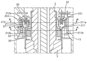
- FIG. 2 is an axial sectional view in the vicinity of the torque sensor 13.
- FIG. 3 is an enlarged view of the torque sensor 13 portion.
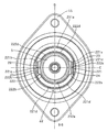
- 4 is a cross-sectional view taken along the line AA in FIG.
- FIG. 5 is a cross-sectional view taken along the line BB in FIG.
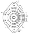
- FIG. 6 is a view of the magnetism collecting unit 27 as viewed from the steering wheel 2 side.
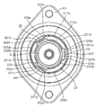
- FIG. 7 is a view of the magnetism collecting unit 27 as viewed from the pinion 8 side.
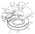
- FIG. 8 is a perspective view of the magnetic flux collecting unit 27 and the circuit board 30.
- the torque sensor 13 is accommodated in the steering gear box 15. One end of the torsion bar 6 is fixed to the input shaft 5.
- the other end of the torsion bar 6 is fixed to the pinion shaft 7.
- the input shaft 5 and the pinion shaft 7 are not directly connected, and both are supported so as to be relatively rotatable.
- the torque sensor 13 obtains the steering torque from the magnitude of this deviation.
- the pinion shaft 7 is provided with a magnet 20 formed in an annular shape.
- the magnets 20 are alternately arranged in the circumferential direction with N poles and S poles.
- Example 1 has 16 poles in the circumferential direction.
- the magnet 20 rotates integrally with the pinion shaft 7.
- the yoke member 21 includes a first yoke member 211 and a second yoke member 212.
- the first yoke member 211 is made of permalloy (soft magnetic alloy).
- the first yoke member 211 has a first annular portion 211a formed in an annular shape.
- the first annular portion 211a is formed to have a larger diameter than the outer diameter of the magnet 20.
- the first yoke member 211 has a first claw portion 211b extending in the axial direction after being bent inward from the first annular portion 211a. Eight first claw portions 211b are provided at equal intervals in the circumferential direction.
- the interval between the adjacent first claw portions 211b is formed to be substantially the same as or slightly wider than the circumferential width of the first claw portion 211b.
- the diameter of the circle formed by connecting the outer peripheral surface of the first claw portion 211b in the circumferential direction is formed larger than the outer diameter of the magnet 20.
- the second yoke member 212 is made of permalloy.
- the second yoke member 212 has a second annular portion 212a formed in an annular shape.
- the second annular portion 212 a is formed with a smaller diameter than the outer diameter of the magnet 20.
- the second yoke member 212 has a second claw portion 212b extending in the axial direction after being bent from the second annular portion 212a to the outer peripheral side.
- Eight second claw portions 212b are provided at equal intervals in the circumferential direction.
- the interval between the adjacent second claw portions 212b is formed to be substantially the same as or slightly wider than the circumferential width of the second claw portion 212b.
- the diameter of the circle formed by connecting the outer peripheral surface of the second claw portion 212b in the circumferential direction is formed to be substantially the same as the diameter of the circle formed by connecting the outer peripheral surface of the first claw portion 211b in the circumferential direction.
- the first yoke member 211 and the second yoke member 212 are held by the yoke holder 33.
- the first annular portion 211a and the second annular portion 212a are arranged coaxially, and the first annular portion 211a It is located on the outer peripheral side of the bicyclic ring portion 212a.
- the inner circumferential surface of the first annular portion 211a and the outer circumferential surface of the second annular portion 212a are provided so as to face each other.
- the inner peripheral surface of the first annular portion 211a and the outer peripheral surface of the second annular portion 212a are provided apart from each other.
- the second claw portion 212b is positioned between the adjacent first claw portions 211b. That is, the first claw portions 211b and the second claw portions 212b are alternately arranged.
- the first yoke member 211 and the second yoke member 212 are attached to the input shaft 5 while being held by the yoke holder 33.
- the first yoke member 211 and the second yoke member 212 rotate integrally with the input shaft 5.
- the first claw portion 211b and the second claw portion 212b are disposed on the outer peripheral side of the magnet 20. At this time, the first claw portion 211b and the second claw portion 212b are disposed so that the center positions in the width direction face the boundary position between the N pole and the S pole of the magnet 20.
- a magnetism collecting mechanism 22 is provided between the first annular portion 211a of the first yoke member 211 and the second annular portion 212a of the second yoke member 212.
- the magnetic flux collecting mechanism 22 includes a first magnetic flux collecting mechanism 221 and a second magnetic flux collecting mechanism 222.
- the first magnetic flux collecting mechanism 221 is made of permalloy.
- the first magnetic flux collecting mechanism 221 is arranged to face the first annular portion 211a.
- the first magnetic flux collecting mechanism 221 is disposed so as to be separated from the first annular portion 211a.
- the first magnetic flux collecting mechanism 221 includes a first magnetic flux collecting member 221a and a second magnetic flux collecting member 221b.
- the first magnetism collecting member 221a and the second magnetism collecting member 221b are formed in the same shape.
- the first magnetism collecting member 221a and the second magnetism collecting member 221b are viewed from the rotation axis direction of the input shaft 5, the first magnetism collecting member 221a and the second magnetism collecting member 221b are linearly formed.
- 221c and an arc-shaped portion 221d extending in an arc shape from both ends of the magnetism collecting portion 221c.
- the magnetism collecting part 221c is formed so as to be positioned on the inner peripheral side of a virtual circle formed by extending the arcuate part 221d.
- the first magnetism collecting member 221a and the second magnetism collecting member 221b are formed in an arc shape along the circumferential direction of the rotation shaft of the input shaft 5 as a whole.
- the first magnetic flux collecting member 221a and the second magnetic flux collecting member 221b are formed so that the circumferential width of the rotation shaft of the input shaft 5 is slightly smaller than 180 degrees.
- the circumferential end of the first magnetic flux collecting member 221a and the circumferential edge of the second magnetic flux collecting member 221b are arranged so as not to contact each other.
- the first magnetism collecting member 221a and the second magnetism collecting member 221b are plate-like members having a width in the rotation axis direction of the input shaft 5. That is, the first magnetic flux collecting member 221a and the second magnetic flux collecting member 221b are arranged so as to overlap the first annular portion 211a in the rotational axis direction and the circumferential direction of the input shaft 5.
- the second magnetism collecting mechanism 222 is made of permalloy.
- the second magnetism collecting mechanism 222 is disposed so as to face the second annular portion 212a.
- the second magnetism collecting mechanism 222 is disposed away from the second annular portion 212a.
- the second magnetism collecting mechanism 222 includes a third magnetism collecting member 222a and a fourth magnetism collecting member 222b.
- the third magnetism collecting member 222a and the fourth magnetism collecting member 222b are formed in the same shape. When the third magnetic flux collecting member 222a and the fourth magnetic flux collecting member 222b are viewed from the rotation axis direction of the input shaft 5, the third magnetic flux collecting member 222a and the fourth magnetic flux collecting member 222b are linearly formed.
- the magnetism collecting part 221c is formed so as to be positioned on the outer peripheral side of an imaginary circle formed by extending the arcuate part 221d.
- the third magnetism collecting member 222a and the fourth magnetism collecting member 222b are formed in an arc shape along the circumferential direction of the rotation shaft of the input shaft 5 as a whole.
- the third magnetism collecting member 222a and the fourth magnetism collecting member 222b are formed so that the width in the circumferential direction of the rotation shaft of the input shaft 5 is slightly smaller than 180 degrees.
- the circumferential end of the third magnetism collecting member 222a and the circumferential end of the fourth magnetism collecting member 222b are arranged so as not to contact each other.
- the third magnetism collecting member 222a and the fourth magnetism collecting member 222b are plate-like members having a width in the rotation axis direction of the input shaft 5. That is, the third magnetic flux collecting member 222a and the fourth magnetic flux collecting member 222b are arranged so as to overlap the second annular portion 212a in the rotation axis direction and the circumferential direction of the input shaft 5.
- the first magnetic flux collecting member 221a, the second magnetic flux collecting member 221b, the third magnetic flux collecting member 222a, and the fourth magnetic flux collecting member 222b are provided on the same plane perpendicular to the rotation axis of the input shaft 5.
- the magnetism collecting part 221c of the first magnetism collecting member 221a, the magnetism collecting part 221c of the second magnetism collecting member 221b, and the magnetism collecting part 222c of the third magnetism collecting member 222a are orthogonal to the rotation axis O of the input shaft 5.
- a straight line orthogonal to the magnetic collecting part 222c of the fourth magnetic collecting member 222b is defined as a straight line C.
- the magnetic flux collecting portion 221c of the first magnetic flux collecting member 221a, the magnetic flux collecting portion 221c of the second magnetic flux collecting member 221b, the magnetic flux collecting portion 222c of the third magnetic flux collecting member 222a and the first magnetic flux collecting member 221a are orthogonal to the rotational axis O of the input shaft 5.
- a straight line parallel to the magnetic collecting portion 222c of the four magnetic collecting members 222b is defined as a straight line D.
- the first magnetic flux collecting member 221a, the second magnetic flux collecting member 221b, the third magnetic flux collecting member 222a, and the fourth magnetic flux collecting member 222b are each formed in a symmetrical shape with respect to the straight line C.
- the first magnetism collecting member 221a and the second magnetism collecting member 221b are arranged so as to be symmetrical with respect to the straight line D.
- the third magnetism collecting member 222a and the fourth magnetism collecting member 222b are arranged so as to have a target shape with respect to the straight line D.
- the first magnetism collecting member 221a and the second magnetism collecting member 221b are arranged so as to be symmetrical with respect to the rotation axis O of the input shaft 5.
- the third magnetism collecting member 222a and the fourth magnetism collecting member 222b are arranged so as to be symmetrical with respect to the rotation axis O of the input shaft 5.
- the magnetism collecting mechanism 22 is held by a holder member 28 formed by injection molding with a resin material that is an insulating member.
- the magnetic flux collecting mechanism 22 is formed integrally with the holder member 28 by insert molding.
- the holder member 28 and the magnetism collecting member 22 constitute a magnetism collecting unit 27.
- the outer shape of the holder member 28 is generally formed in a bottomed cup shape, and has an opening 282 at the center of the bottom.
- the input shaft 5 passes through the opening 282.
- the bottom surface of the holder member 28 is provided with a gate portion 281 into which a resin material is injected when the holder member 28 is injection molded. There are six gate portions 281 (gate portions 281a, 281b, 281c, 281d, 281e, 281f).
- the six gate portions 281 are provided at positions symmetrical with respect to the straight line C and the straight line D. That is, the gate portion 281 is provided symmetrically with respect to the first magnetic flux collecting mechanism 221 and the second magnetic flux collecting mechanism 222.
- a flange portion 283 protrudes from the outer peripheral surface of the holder member 28, and a cylindrical column portion 284 is formed at the tip of the flange portion 283.
- the cylindrical portion 284 is formed with a bolt hole 284a into which a bolt for fixing the magnetism collecting unit 27 to the steering gear box 15 is inserted.
- a cylindrical positioning portion 285 that protrudes from a surface on the steering wheel 2 side when the magnetism collecting unit 27 is attached to the steering gear box 15 at the bottom of the holder member 28 is provided.
- the positioning unit 285 is inserted into a positioning hole 301 of the circuit board 30 described later, and positions the circuit board 30 with respect to the magnetic flux collecting unit 27.
- a magnetic sensor insertion hole 286a that communicates between the magnetism collecting part 221c of the first magnetism collecting member 221a and the magnetism collecting part 222c of the third magnetism collecting member 222a, and the second magnetism collecting member 221b
- a magnetic sensor insertion hole 286b communicating with the magnetic flux collecting portion 221c and the magnetic flux collecting portion 222c of the fourth magnetic flux collecting member 222b is formed.
- a first magnetic sensor 23 and a second magnetic sensor 24, which will be described later, are inserted between the magnetic flux collecting portion 221c of the first magnetic flux collecting member 221a and the magnetic flux collecting portion 222c of the third magnetic flux collecting member 222a through the magnetic sensor insertion hole 286a.
- a third magnetic sensor 25 and a fourth magnetic sensor 26, which will be described later, are inserted between the magnetic flux collecting portion 221c of the second magnetic flux collecting member 221b and the magnetic flux collecting portion 222c of the fourth magnetic flux collecting member 222b through the magnetic sensor insertion hole 286b.
- a portion inserted between the first annular portion 211a of the first yoke member 211 and the second annular portion 212a of the second yoke member 212 is The resin member forming the holder member 28 is not covered and exposed.
- a welding plate 29 is provided so as to straddle the adjacent first magnetic flux collecting mechanism 221 and second magnetic flux collecting mechanism 222.
- the welding plate 29 is formed in an annular shape using a thermoplastic resin. The welding plate 29 is ultrasonically welded while being in contact with the first magnetism collecting mechanism 221 and the second magnetism collecting mechanism 222.
- a first magnetic sensor 23 and a second magnetic sensor 24 are provided between the magnetic flux collecting portion 221c of the first magnetic flux collecting member 221a and the magnetic flux collecting portion 222c of the third magnetic flux collecting member 222a.
- a third magnetic sensor 25 and a fourth magnetic sensor 26 are provided between the magnetism collecting part 221c of the second magnetism collecting member 221b and the magnetism collecting part 222c of the fourth magnetism collecting member 222b.
- the first magnetic sensor 23, the second magnetic sensor 24, the third magnetic sensor 25, and the fourth magnetic sensor 26 are formed by Hall elements.
- the first magnetic sensor 23 and the second magnetic sensor 24 are arranged at positions that are symmetric with respect to the straight line C.
- the third magnetic sensor 25 and the fourth magnetic sensor 26 are arranged at positions that are symmetric with respect to the straight line C.
- the first magnetic sensor 23 and the fourth magnetic sensor 26 are arranged at positions that are symmetric with respect to the straight line D.
- the second magnetic sensor 24 and the third magnetic sensor 25 are arranged at positions symmetrical with respect to the straight line D.
- the first magnetic sensor 23 and the third magnetic sensor 25 are provided at symmetrical positions with respect to the rotation axis O of the input shaft 5.
- the second magnetic sensor 24 and the fourth magnetic sensor 26 are provided at symmetrical positions with respect to the rotation axis O of the input shaft 5.
- the positions at which the first magnetic sensor 23, the second magnetic sensor 24, the third magnetic sensor 25, and the fourth magnetic sensor 26 are disposed are in the magnetic environment (the positions of the claws 211b and 212b of the magnet 20 and the yoke member 21). , And the like with respect to the magnetic flux collecting member 22).
- the magnetic flux lines detected by the first magnetic sensor 23, the second magnetic sensor 24, the third magnetic sensor 25, and the fourth magnetic sensor 26 are different, magnetic flux lines having the same characteristics can be detected. Therefore, the detection values of the first magnetic sensor 23, the second magnetic sensor 24, the third magnetic sensor 25, and the fourth magnetic sensor 26 are equal.
- the first magnetic sensor 23, the second magnetic sensor 24, the third magnetic sensor 25, and the fourth magnetic sensor 26 have output terminals 23a, 24a, 25a, and 26a for outputting signals, respectively.
- the output terminals 23a, 24a, 25a, 26a extend in the same direction as the rotation axis direction of the input shaft 5. Is arranged in.
- the output terminals 23a, 24a, 25a, and 26a are connected to the same circuit board 30.
- the first magnetic sensor 23, the second magnetic sensor 24, the third magnetic sensor 25, and the fourth magnetic sensor 26 are inserted into the magnetic sensor insertion holes 286a and 286b of the holder member 28 while being attached to the circuit board 30. .
- a connector part 32 to which a harness 31 connected to an external controller 14 described later is attached is provided on the circuit board 30, a connector part 32 to which a harness 31 connected to an external controller 14 described later is attached is provided. Output signals of the first magnetic sensor 23, the second magnetic sensor 24, the third magnetic sensor 25, and the fourth magnetic sensor 26 are output from the connector unit 32 to the controller 14.
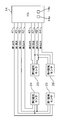
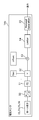
- FIG. 9 is a circuit diagram between the first magnetic sensor 23, the second magnetic sensor 24, the third magnetic sensor 25, the fourth magnetic sensor 26, and the controller 14.
- the three magnetic sensor 25 and the fourth magnetic sensor 26 are connected to the controller 14 by a first output circuit 41, a second output circuit 42, a third output circuit 43, and a fourth output circuit 44, respectively.
- the first output circuit 41, the second output circuit 42, the third output circuit 43, and the fourth output circuit 44 are outputs of the first magnetic sensor 23, the second magnetic sensor 24, the third magnetic sensor 25, and the fourth magnetic sensor 26.
- a signal is sent to the controller 14.
- the first magnetic sensor 23 and the second magnetic sensor 24 are connected to the controller 14 by a common first power supply circuit 45.
- the third magnetic sensor 25 and the fourth magnetic sensor 26 are connected to the controller 14 by a common second power supply circuit 47.
- the first power supply circuit 45 and the second power supply circuit 47 supply power to the first magnetic sensor 23, the second magnetic sensor 24, the third magnetic sensor 25, and the fourth magnetic sensor 26.
- the first magnetic sensor 23 and the second magnetic sensor 24 are connected to the controller 14 by a common first ground circuit 46.
- the third magnetic sensor 25 and the fourth magnetic sensor 26 are connected to the controller 14 by a common second ground circuit 48.
- the first ground circuit 46 and the second ground circuit 48 connect the first magnetic sensor 23, the second magnetic sensor 24, the third magnetic sensor 25, and the fourth magnetic sensor 26 to the ground.
- the controller 14 has an abnormality detection unit 14a that detects an abnormality in the first power circuit 45, the first ground circuit 46, the second power circuit 47, and the second ground circuit 48.
- the controller 14 has an output adjustment unit 14b.
- the output adjustment unit 14b reduces the difference in output signals caused by the error of each product of the first magnetic sensor 23, the second magnetic sensor 24, the third magnetic sensor 25, and the fourth magnetic sensor 26 and the error of the mounting position.
- FIG. 10 is a control block diagram of the output adjustment unit 14b.
- the A / D converter 50 the signals output from the first magnetic sensor 23, the second magnetic sensor 24, the third magnetic sensor 25, and the fourth magnetic sensor 26 are converted from analog signals to digital signals.
- the low pass filter 51 removes high frequency noise from the signal output from the A / D conversion unit 50.
- the gain adjustment unit 52 multiplies the gain.
- the offset adjustment unit 53 adds the offset value.
- the gain and the offset value are values that are adjusted during calibration before shipping the torque sensor 13.
- the gain and offset values output almost equal output signals regardless of the product-specific errors or mounting position errors of the first magnetic sensor 23, the second magnetic sensor 24, the third magnetic sensor 25, and the fourth magnetic sensor 26.
- the limiter 54 limits excessive signals.
- the protocol generation unit 55 converts the signal into a signal conforming to the communication method and outputs it.
- the first magnetic sensor 23, the second magnetic sensor 24, the third magnetic sensor 25, and the fourth magnetic sensor 26 output an intermediate voltage.
- the torsion bar 6 is twisted, and a relative angular displacement is generated between the input shaft 5 and the pinion shaft 7.
- This relative angular displacement appears as a relative angular displacement between the claw portions 211b and 212b and the magnet 20.
- the balance of permeance with respect to the N pole and S pole of the magnet 20 viewed from the claw portions 211b and 212b is lost.
- Magnetic flux generated from the N pole of the magnet 20 flows in a direction in which the area facing the N pole of the claws 211b and 212b is wide. Therefore, a magnetic flux flows between the first magnetic flux collecting mechanism 221 and the second magnetic flux collecting mechanism 222.
- the first magnetic sensor 23, the second magnetic sensor 24, the third magnetic sensor 25, and the fourth magnetic sensor 26 detect the amount of flowing magnetic flux and output a signal corresponding to the detected amount of magnetic flux. Thereby, the amount of twist of the torsion bar 3 can be detected, and the steering torque can be obtained from the rigidity of the torsion bar 3.
- the magnetic environment is the same at the positions where the first magnetic sensor 23, the second magnetic sensor 24, the third magnetic sensor 25, and the fourth magnetic sensor 26 are arranged.
- the characteristics of the magnetic flux lines passing through the first magnetic sensor 23, the second magnetic sensor 24, the third magnetic sensor 25, and the fourth magnetic sensor 26 become substantially equal, and variations in the output signal characteristics of each sensor are suppressed. can do. Therefore, the stability of the detection accuracy of the steering torque can be improved.
- the first magnetic flux collecting mechanism 221 is formed in an arc shape along the circumferential direction of the rotation shaft of the input shaft 5.
- the second magnetism collecting mechanism 222 was formed in an arc shape along the circumferential direction of the rotation shaft of the input shaft 5.
- the second magnetic flux collecting mechanism 222 is provided so as to overlap the first magnetic flux collecting mechanism 221 in the direction of the rotation axis of the input shaft 5 and in the circumferential direction.
- the second magnetic flux collecting mechanism 222 is provided so as to be separated from the first magnetic flux collecting mechanism 221 in the radial direction of the rotation shaft of the input shaft 5.
- the positions of the first magnetic sensor 23, the second magnetic sensor 24, the third magnetic sensor 25, and the fourth magnetic sensor 26 with respect to the first magnetic collecting mechanism 221 and the second magnetic collecting mechanism 222 are in the direction of the rotational axis of the input shaft 5. Even if it deviates, the change of magnetic flux detected by the first magnetic sensor 23, the second magnetic sensor 24, the third magnetic sensor 25, and the fourth magnetic sensor 26 can be suppressed.
- the first magnetic sensor 23, the second magnetic sensor 24, the third magnetic sensor 25, and the fourth magnetic sensor 26 are configured such that the output terminals 23a, 24a, 25a, and 26a of the sensors are the rotation shafts of the input shaft 5. It is arranged so as to extend in the same direction toward the direction. Thus, the first magnetic sensor 23, the second magnetic sensor 24, the third magnetic sensor 25, and the fourth magnetic sensor 26 are inserted between the first magnetic collecting mechanism 221 and the second magnetic collecting mechanism 222 from the same direction. Thus, assembly of the torque sensor 13 is facilitated.
- the output terminals 23a, 24a, 25a, and 26a of the first magnetic sensor 23, the second magnetic sensor 24, the third magnetic sensor 25, and the fourth magnetic sensor 26 are connected to the same controller 14. .
- the configuration of the torque sensor 13 can be simplified, and the assembly becomes easy.
- output signals from the first magnetic sensor 23, the second magnetic sensor 24, the third magnetic sensor 25, and the fourth magnetic sensor 26 are output from the connector portion 32 to the controller 14.
- the configuration of the torque sensor 13 can be simplified.
- the first magnetic flux collecting mechanism 221 and the second magnetic flux collecting mechanism 222 are fixed by the holder member 28 formed of an insulating material.
- the first magnetic sensor 23, the second magnetic sensor 24, the third magnetic sensor 25, and the fourth magnetic sensor 26 are arranged because displacement of the first magnetic collecting mechanism 221 and the second magnetic collecting mechanism 222 is suppressed.
- the magnetic environment at the specified position can be stably maintained.
- the holder member 28 is injection-molded with a resin material together with the first magnetic flux collecting mechanism 221 and the second magnetic flux collecting mechanism 222. This eliminates the need for separately assembling the first magnetism collecting mechanism 221 and the second magnetism collecting mechanism 222 to the torque sensor 13, and the assembling work of the torque sensor 13 can be simplified.
- the gate portion 281 when the holder member 28 is injection-molded is provided at a position symmetrical to the first magnetic flux collecting mechanism 221 and the second magnetic flux collecting mechanism 222. Internal stress acts on the first magnetic flux collecting mechanism 221 and the second magnetic flux collecting mechanism 222 during injection molding. When the internal stress acts, the magnetic environment of the first magnetic flux collecting mechanism 221 and the second magnetic flux collecting mechanism 222 changes.
- the magnetic environment at the position where the first magnetic sensor 23, the second magnetic sensor 24, the third magnetic sensor 25, and the fourth magnetic sensor 26 are arranged is equal, and the first magnetic sensor 23, the second magnetic sensor 24, the third Variations in output signal characteristics of the magnetic sensor 25 and the fourth magnetic sensor 26 can be suppressed. Therefore, the stability of the detection accuracy of the steering torque can be improved.
- the first magnetic sensor 23 and the third magnetic sensor 25 are provided at positions symmetrical with respect to the rotation axis O of the input shaft 5.
- the second magnetic sensor 24 and the fourth magnetic sensor 26 are provided at positions symmetrical with respect to the rotation axis O of the input shaft 5.
- the first magnetic flux collecting mechanism 221 and the second magnetic flux collecting mechanism 222 are formed in an arc shape around the rotation axis O of the input shaft 5. By disposing each magnetic sensor at a symmetrical position with respect to the rotation axis O of the same input shaft 5, the position of each magnetic sensor can be set to a position where the magnetic environment is substantially equal.
- the first magnetic flux collecting mechanism 221 includes the first magnetic flux collecting member 221a and the second magnetic flux collecting member 221b.
- the first magnetic flux collecting member 221a and the second magnetic flux collecting member 221b have the same shape.
- the second magnetic flux collecting mechanism 222 is composed of a third magnetic flux collecting member 222a and a fourth magnetic flux collecting member 222b.
- the third magnetism collecting member 222a and the fourth magnetism collecting member 222b have the same shape.
- the first magnetic sensor 23 and the second magnetic sensor 24 are disposed between the first magnetic collecting member 221a and the third magnetic collecting member 222a.
- the third magnetic sensor 25 and the fourth magnetic sensor 26 are disposed between the second magnetic flux collecting member 221b and the fourth magnetic flux collecting member 222b.
- two sets of magnetic flux collecting members that is, a set of the first magnetic flux collecting member 221a and the third magnetic flux collecting member 222a and a set of the second magnetic flux collecting member 221b and the fourth magnetic flux collecting member 222b can be provided.
- the first magnetism collecting member 221a and the second magnetism collecting member 221b have the same shape
- the third magnetism collecting member 222a and the fourth magnetism collecting member 222b have the same shape. equal.
- the first magnetic sensor 23 and the second magnetic sensor 24 are arranged in one set of magnetic flux collecting members
- the third magnetic sensor 25 and the fourth magnetic sensor 26 are arranged in the other magnetic flux collecting member.
- the magnetic environment at the position where the magnetic sensor 23, the second magnetic sensor 24, the third magnetic sensor 25, and the fourth magnetic sensor 26 are disposed can be made substantially equal.
- Example 1 the first magnetic flux collecting member 221a, the second magnetic flux collecting member 221b, the third magnetic flux collecting member 222a, and the fourth magnetic flux collecting member 222b are provided on the same plane perpendicular to the rotation axis of the rotating member 16. . Thereby, the size of the rotating member 16 of the torque sensor 13 in the direction of the rotation axis can be reduced.
- the angle of the circumferential width of the rotation axis of the rotating member 16 of the first magnetic flux collecting member 221a, the second magnetic flux collecting member 221b, the third magnetic flux collecting member 222a, and the fourth magnetic flux collecting member 222b is 180 degrees. Less than. Thereby, two sets of magnetism collecting members can be arranged on the same plane.
- the first magnetic sensor 23 and the second magnetic sensor 24 are connected to the common first power supply circuit 45 and first ground circuit 46.
- the third magnetic sensor 25 and the fourth magnetic sensor 26 are connected to a common second power supply circuit 47 and second ground circuit 48.
- the controller 14 is provided with the abnormality detection unit 14a that detects an abnormality in the first power supply circuit 45, the first ground circuit 46, the second power supply circuit 47, and the second ground circuit 48. For example, even if an abnormality occurs in the first power supply circuit 45, the output signals of the first magnetic sensor 23 and the second magnetic sensor 24 are equal, and thus an abnormality cannot be detected due to a difference in output signals. Or, an abnormal value may be determined as a normal value.
- the abnormality detector 14a in the controller 14 By providing the abnormality detector 14a in the controller 14, the abnormality of the first power circuit 45, the first ground circuit 46, the second power circuit 47, and the second ground circuit 48 that cannot be detected by the output signal of each sensor. Can be detected.
- the output adjustment is performed to reduce the difference between output signals caused by the error of each product and the mounting position of the first magnetic sensor 23, the second magnetic sensor 24, the third magnetic sensor 25, and the fourth magnetic sensor 26.
- a portion 14b is provided.
- the first magnetic sensor 23, the second magnetic sensor 24, the third magnetic sensor 25, and the fourth magnetic sensor 26 are adjusted so that substantially equal output signals are output regardless of the error of each product and the error of the mounting position. Is done.
- a rotating member 16 having a pinion shaft 7 (first axis) and an input shaft 5 (second axis) connected via a torsion bar 6 and the pinion shaft 7 so as to rotate as the pinion shaft 7 rotates.
- the magnet 20 is formed in an annular shape, and the N pole and the S pole are alternately arranged in the circumferential direction, and is provided on the input shaft 5 so as to rotate as the input shaft 5 rotates, and is formed of a magnetic material.
- the first claw portion 211b (first claw portion), which is a plurality of plate-like members arranged to face the magnet 20, and the first circle that is formed in an annular shape and connects the first claw portions 211b to each other
- You A second claw portion 212b (second claw portion) which is a plurality of plate-like members arranged in this manner, and a second annular portion 212a (second second) which is formed in an annular shape and connects the second claw portions 212b to each other
- the first magnetic flux collecting mechanism 221 (first magnetic flux collecting mechanism) formed of a magnetic material is provided so as to face
- a second magnetic flux collecting mechanism 222 (second magnetic flux collecting mechanism) formed of a magnetic material and provided between the first magnetic flux collecting mechanism 221 and the second magnetic flux collecting mechanism 222; Between the first magnetic sensor mechanism 221 and the second magnetic flux collector mechanism 222.
- the first magnetic sensor 23 having a Hall element for detecting a change in the magnetic field between the first magnetic flux collector mechanism 221 and the second magnetic flux collector mechanism 222.
- First magnetic flux collection mechanism provided The Hall element that detects a change in the magnetic field between the magnetic flux collecting mechanism 221 and the second magnetic flux collecting mechanism 222 has the same magnetic environment as the first magnetic sensor 23 between the first magnetic flux collecting mechanism 221 and the second magnetic flux collecting mechanism 222.
- the second magnetic sensor 24 (second magnetic sensor) disposed at a symmetrical position, and provided between the first magnetic flux collecting mechanism 221 and the second magnetic flux collecting mechanism 222, the first magnetic flux collecting mechanism 221 and the second magnetic flux collecting mechanism 222 are provided.
- a Hall element that detects a change in the magnetic field between the magnetic mechanisms 222 and the magnetic environment of the first magnetic sensor 23 and the second magnetic sensor 24 between the first magnetic collecting mechanism 221 and the second magnetic collecting mechanism 222;
- a third magnetic sensor 25 (third magnetic sensor) disposed at the same or symmetrical position, and a rotating member based on an output signal of the first magnetic sensor 23, the second magnetic sensor 24, or the third magnetic sensor 25 Torque generated in 16 was detected. Therefore, even if an abnormality occurs in any of the magnetic sensors, the control using the torque sensor 13 can be continued. In addition, the stability of steering torque detection accuracy can be improved.
- the first magnetic flux collecting mechanism 221 is formed in an arc shape along the circumferential direction of the rotating shaft of the rotating member 16, and the second magnetic flux collecting mechanism 222 is a circle along the circumferential direction of the rotating shaft of the rotating member 16. It is formed in an arc shape so as to overlap with the first magnetic flux collecting mechanism 221 in the direction of the rotation axis of the rotating member 16 and in the circumferential direction, and to be separated from the first magnetic flux collecting mechanism 221 in the radial direction of the rotating shaft of the rotating member 16
- the first magnetic sensor 23, the second magnetic sensor 24, and the third magnetic sensor 25 are provided between the first magnetic collecting mechanism 221 and the second magnetic collecting mechanism 222 in the radial direction of the rotation shaft of the rotating member 16. It was made to be.
- the first magnetic sensor 23, the second magnetic sensor 24, and the third magnetic sensor 25 include output terminals 23a, 24a, and 25a for outputting an output signal, and the first magnetic sensor 23 and the second magnetic sensor 24 and the output terminals 23a, 24a, 25a of the third magnetic sensor 25 are provided so as to extend in the same direction in the direction of the rotation axis of the rotating member 16. Therefore, the assembly of the torque sensor 13 is facilitated.
- the first magnetic sensor 23, the second magnetic sensor 24, and the third magnetic sensor 25 have a single circuit board 30 to which the output terminals 23a, 24a, and 25a are connected. Therefore, the configuration of the torque sensor 13 can be simplified and assembly is facilitated.
- the holder member 28 (holding member) is formed of an insulating material and to which the first magnetic flux collecting mechanism 221 and the second magnetic flux collecting mechanism 222 are fixed. Therefore, the magnetic environment at the position where the first magnetic sensor 23, the second magnetic sensor 24, and the third magnetic sensor 25 are disposed can be stably maintained.
- the holder member 28 (holding member) is formed by injection molding with a resin material and fixes the first magnetic flux collecting mechanism 221 and the second magnetic flux collecting mechanism 222 by insert molding. Therefore, the assembly work of the torque sensor 13 can be simplified.
- the gate portion 281 for injection-molding the holder member 28 is provided at a position symmetrical to each of the first magnetic flux collecting mechanism 221 and the second magnetic flux collecting mechanism 222. Therefore, the stability of the detection accuracy of the steering torque can be improved.
- the first magnetic flux collecting mechanism 221 is formed in an arc shape along the circumferential direction of the rotating shaft of the rotating member 16, and the second magnetic flux collecting mechanism 222 is a circle along the circumferential direction with respect to the rotating shaft of the rotating member 16.
- the first magnetic sensor 23, the second magnetic sensor 24, and the third magnetic sensor 25 are provided at positions symmetrical to each other with respect to the rotation axis of the rotating member 16. Therefore, the magnetic environment at the position where the first magnetic sensor 23, the second magnetic sensor 24, and the third magnetic sensor 25 are disposed can be made substantially equal.
- the first magnetic flux collecting mechanism 221 includes a first magnetic flux collecting member 221a (first magnetic flux collecting member) and a second magnetic flux collecting member 221b (second magnetic flux collecting member) having the same shape as the first magnetic flux collecting member 221a.
- the second magnetic flux collecting mechanism 222 includes a third magnetic flux collecting member 222a (third magnetic flux collecting member) provided to face and separate from the first magnetic flux collecting member 221a,
- the first magnetic sensor 23 includes a fourth magnetic flux collecting member 222b (fourth magnetic flux collecting member) which is provided so as to face and separate from the magnetic flux collecting member 221b and has the same shape as the third magnetic flux collecting member 222a.
- One of the second magnetic sensor 24 and the third magnetic sensor 25 is disposed between the first magnetic collecting member 221a and the third magnetic collecting member 222a, and at least one of the remaining two, It is arranged between the second magnetic flux collecting member 221b and the fourth magnetic flux collecting member 222b. Therefore, the magnetic environment at the position where the first magnetic sensor 23, the second magnetic sensor 24, and the third magnetic sensor 25 are disposed can be made substantially equal.
- the first magnetic flux collecting member 221a, the second magnetic flux collecting member 221b, the third magnetic flux collecting member 222a, and the fourth magnetic flux collecting member 222b are provided on the same plane perpendicular to the rotation axis of the rotating member 16.
- the angle of the circumferential width of the rotating shaft of the rotating member 16 of the first magnetic collecting member 221a, the second magnetic collecting member 221b, the third magnetic collecting member 222a, and the fourth magnetic collecting member 222b is less than 180 degrees. . Therefore, it is possible to improve the layout when arranging multiple sets (two sets) of magnetic flux collecting members.
- the first magnetic collecting mechanism 221 and the second magnetic collecting mechanism 222 are formed symmetrically with respect to the rotation axis of the rotating member 16, and the first magnetic sensor 23, the second magnetic sensor 24, and the third magnetic sensor 25 are formed. Are arranged at positions symmetrical to each other with respect to the rotation axis of the rotation member 16. Therefore, the magnetic environment at the position where the first magnetic sensor 23, the second magnetic sensor 24, and the third magnetic sensor 25 are disposed can be made substantially equal.
- the first magnetic sensor 23, the second magnetic sensor 24, and the third magnetic sensor 25 are connected to the power supply circuits 45 and 47, the ground circuits 46 and 48, and the controller 14 (microprocessor).
- At least two of the sensor 23, the second magnetic sensor 24, and the third magnetic sensor 25 are connected to a common first power circuit 45 and a common first ground circuit 46, and the controller 14 includes power circuits 45, 47 and An abnormality detecting unit 14a for detecting an abnormality in the ground circuits 46 and 48 is provided. Therefore, the circuit can be simplified. Further, it is possible to detect an abnormality in the power supply circuits 45 and 47 and the ground circuits 46 and 48 that cannot detect an abnormality from the output signals of the sensors. (15) Outputs of the first magnetic sensor 23, the second magnetic sensor 24, and the third magnetic sensor 25 by applying a gain to the output signals of the first magnetic sensor 23, the second magnetic sensor 24, and the third magnetic sensor 25 An output adjustment unit 14b that reduces the signal difference is provided. The error of the output signals of the first magnetic sensor 23, the second magnetic sensor 24, and the third magnetic sensor 25 can be reduced, and the steering torque detection accuracy of the torque sensor 13 can be improved.
- An input shaft 5 (steering shaft) having a pinion shaft 7 (first shaft) and an input shaft 5 (second shaft) connected via a torsion bar 6 and rotating in accordance with the steering operation of the steering wheel 2;
- a steering mechanism 17 having a rack bar 9 for transmitting the rotation of the input shaft 5 to the steered wheels 4, a torque sensor 13 for detecting a steering torque generated in the steering mechanism 17, and a drive control based on the steering torque.
- the torque sensor 13 is rotated with the rotation of the pinion shaft 7.
- the magnet 20 is provided on the pinion shaft 7 and formed in an annular shape, with N and S poles arranged alternately in the circumferential direction, and the input shaft 5 is rotated.
- a first claw portion 211b (first claw portion) that is a plurality of plate-like members that are provided on the input shaft 5 so as to rotate, are formed of a magnetic material, and are arranged to face the magnet 20.
- a first yoke member 211 having a first annular portion 211a (first annular portion) that connects the first claw portions 211b to each other, and an input shaft that rotates as the input shaft 5 rotates
- the second claw portion 212b (second claw portion), which is a plurality of plate-like members that are provided in 5 and are formed of a magnetic material and arranged to face the magnet 20, and a second claw that is formed in an annular shape
- Second annular portions 212a (second annular portions) for connecting the portions 212b to each other, and the second claw portions 212b are alternately arranged between the respective claw portions of the first claw portions 211b.
- the second yoke member 212 disposed on the first annular portion 211a is opposed to and separated from the first annular portion 211a.
- the first magnetic flux collecting mechanism 221 (first magnetic flux collecting mechanism) made of a magnetic material and the second magnetic flux collecting material formed to be opposed to and spaced apart from the second annular portion 212a.
- the magnetic mechanism 222 (second magnetic flux collecting mechanism) is provided between the first magnetic flux collecting mechanism 221 and the second magnetic flux collecting mechanism 222, and the magnetic field between the first magnetic flux collecting mechanism 221 and the second magnetic flux collecting mechanism 222 is Provided between the first magnetic sensor 23 (first magnetic sensor) having a Hall element for detecting a change, the first magnetic collecting mechanism 221 and the second magnetic collecting mechanism 222, and the first magnetic collecting mechanism 221 and the second magnetic collecting mechanism 221 It has a Hall element that detects a change in the magnetic field between the magnetic flux collecting mechanisms 222, and is located at the same or symmetrical position as the magnetic environment of the first magnetic sensor 23 between the first magnetic flux collecting mechanism 221 and the second magnetic flux collecting mechanism 222.
- the second magnetic sensor 24 (second magnetic sensor), the first magnetic flux collecting mechanism 221 and the second magnetic flux collecting mechanism 222 are provided between the first magnetic flux collecting mechanism 221 and the second magnetic flux collecting mechanism 222.
- It has a Hall element that detects a change in the magnetic field, and is arranged in the same or symmetrical position as the magnetic environment of the first magnetic sensor 23 and the second magnetic sensor 24 between the first magnetic collecting mechanism 221 and the second magnetic collecting mechanism 222
- the third magnetic sensor 25 is provided. Therefore, even if an abnormality occurs in any of the magnetic sensors, the control using the torque sensor 13 can be continued. In addition, the stability of steering torque detection accuracy can be improved.
- the first magnetic flux collecting mechanism 221 is formed in an arc shape along the circumferential direction of the rotating shaft of the rotating member 16, and the second magnetic flux collecting mechanism 222 is a circle along the circumferential direction of the rotating shaft of the rotating member 16. It is formed in an arc shape so as to overlap with the first magnetic flux collecting mechanism 221 in the direction of the rotation axis of the rotating member 16 and in the circumferential direction, and to be separated from the first magnetic flux collecting mechanism 221 in the radial direction of the rotating shaft of the rotating member 16
- the first magnetic sensor 23, the second magnetic sensor 24, and the third magnetic sensor 25 are provided between the first magnetic collecting mechanism 221 and the second magnetic collecting mechanism 222 in the radial direction of the rotation shaft of the rotating member 16. It was made to be.
- Example 2 In Example 1, the first magnetic sensor 23 and the second magnetic sensor 24 are provided between the first magnetic collecting member 221a and the third magnetic collecting member 222a, and the second magnetic collecting member 221b and the fourth magnetic collecting member 222b are provided. The third magnetic sensor 25 and the fourth magnetic sensor 26 are provided between them. On the other hand, in Example 2, the third magnetic flux collecting member 222a and the fourth magnetic flux collecting member 222b are eliminated, and the first magnetic sensor 23 and the second magnetic flux collecting member 222a are disposed between the first magnetic flux collecting member 221a and the third magnetic flux collecting member 222a. The difference is that a sensor 24, a third magnetic sensor 25, and a fourth magnetic sensor 26 are provided.
- the electric power steering apparatus 1 according to the second embodiment will be described.
- FIG. 11 is a cross-sectional view around the first magnetic sensor 23, the second magnetic sensor 24, the third magnetic sensor 25, and the fourth magnetic sensor 26 of the torque sensor 13.
- the first magnetic flux collecting member 221a and the third magnetic flux collecting member 222a have the same shape as the first magnetic flux collecting member 221a and the third magnetic flux collecting member 222a of the first embodiment.
- the first magnetic sensor 23 is disposed between the magnetic flux collecting portion 221c of the first magnetic flux collecting member 221a (first magnetic flux collecting mechanism 221) and the magnetic flux collecting portion 222c of the third magnetic flux collecting member 222a (second magnetic flux collecting mechanism 222).
- a second magnetic sensor 24, a third magnetic sensor 25, and a fourth magnetic sensor 26 are provided.
- the first magnetic sensor 23 and the third magnetic sensor 25 are arranged on the same straight line in the direction of the magnetic field formed between the first magnetic collecting mechanism 221 and the second magnetic collecting mechanism 222.
- the second magnetic sensor 24 and the fourth magnetic sensor 26 are arranged on the same straight line in the direction of the magnetic field formed between the first magnetic flux collecting mechanism 221 and the second magnetic flux collecting mechanism 222.
- Example 2 the first magnetic sensor 23 and the third magnetic sensor 25 are arranged on the same straight line in the direction of the magnetic field.
- the second magnetic sensor 24 and the fourth magnetic sensor 26 are arranged on the same straight line in the direction of the magnetic field.
- the magnetic environment is equal.
- the magnetic environment can be made equal at the position where the first magnetic sensor 23 and the third magnetic sensor 25 are disposed and at the position where the second magnetic sensor 24 and the fourth magnetic sensor 26 are disposed.
- [effect] (18) The direction of the magnetic field formed between at least two of the first magnetic sensor 23, the second magnetic sensor 24, and the third magnetic sensor 25 between the first magnetic collecting mechanism 221 and the second magnetic collecting mechanism 222 In the same straight line. Therefore, the magnetic environment at the position where the first magnetic sensor 23, the second magnetic sensor 24, and the third magnetic sensor 25 are disposed can be made substantially equal.
- Example 3 In Example 1, the first magnetic sensor 23 and the second magnetic sensor 24 are provided between the first magnetic collecting member 221a and the third magnetic collecting member 222a, and the second magnetic collecting member 221b and the fourth magnetic collecting member 222b are provided. The third magnetic sensor 25 and the fourth magnetic sensor 26 are provided between them. On the other hand, in Example 3, the third magnetism collecting member 222a and the fourth magnetism collecting member 222b are abolished, the first magnetic sensor 23 and the third magnetic sensor 25 are provided in one chip, and the second magnetic element is provided in the other chip. The difference is that a sensor 24 and a fourth magnetic sensor 26 are provided.
- the electric power steering apparatus 1 according to the third embodiment will be described.
- FIG. 12 is a cross-sectional view of the vicinity of the first magnetic sensor 23, the second magnetic sensor 24, the third magnetic sensor 25, and the fourth magnetic sensor 26 of the torque sensor 13.
- the first magnetic flux collecting member 221a and the third magnetic flux collecting member 222a have the same shape as the first magnetic flux collecting member 221a and the third magnetic flux collecting member 222a of the first embodiment.
- the first magnetic sensor 23 is disposed between the magnetic flux collecting portion 221c of the first magnetic flux collecting member 221a (first magnetic flux collecting mechanism 221) and the magnetic flux collecting portion 222c of the third magnetic flux collecting member 222a (second magnetic flux collecting mechanism 222).
- a second magnetic sensor 24, a third magnetic sensor 25, and a fourth magnetic sensor 26 are provided.
- the first magnetic sensor 23 and the third magnetic sensor 25 are mounted on the same chip.
- the second magnetic sensor 24 and the fourth magnetic sensor 26 are mounted on the same chip.
- the first magnetic sensor 23 and the third magnetic sensor 25 are mounted on the same chip, and the second magnetic sensor 24 and the fourth magnetic sensor 26 are mounted on the same chip. Magnetic sensors mounted on the same chip are provided at very close positions. Thereby, the magnetic environment of each magnetic sensor can be made equal.
- Example 4 In the first embodiment, the first magnetic sensor 23, the second magnetic sensor 24, the third magnetic sensor 25, and the fourth magnetic sensor 26 are configured so that the output terminals 23a, 24a, 25a, and 26a are in the same direction as the rotation axis direction of the input shaft 5. It was arranged in a state extending toward On the other hand, in Example 4, the first magnetic sensor 23, the second magnetic sensor 24, the third magnetic sensor 25, and the fourth magnetic sensor 26 are configured such that the output terminals 23a, 24a, 25a, and 26a are the diameters of the rotation shafts of the input shaft 5. It differs in that it is arranged in a state extending in the same direction.
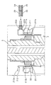
- FIG. 13 is a sectional view of the vicinity of the torque sensor 13.
- the first annular portion 211a of the first yoke member 211 is bent radially outward.
- the second annular portion 212a of the second yoke member 212 is bent radially outward.
- a first magnetic flux collecting mechanism 221 is provided at the end of the first annular portion 211a so as to extend radially outward.
- a second magnetism collecting mechanism 222 is provided at the end of the second annular portion 212a so as to extend outward in the radial direction.
- the first magnetic sensor 23 and the second magnetic sensor 24 are inserted adjacent to each other.
- the first magnetic sensor 23 and the second magnetic sensor 24 are inserted from the radial direction with respect to the rotation axis of the input shaft 5.
- the third magnetic sensor 25 and the fourth magnetic sensor 26 are inserted adjacent to each other.
- the third magnetic sensor 25 and the fourth magnetic sensor 26 are inserted from the radial direction with respect to the rotation axis of the input shaft 5.
- the position at which the first magnetic sensor 23 and the second magnetic sensor 24 are provided and the position at which the third magnetic sensor 25 and the fourth magnetic sensor 26 are provided are set at positions symmetrical with respect to the rotation axis of the input shaft 5. Yes.
- the first magnetic sensor 23, the second magnetic sensor 24, the third magnetic sensor 25, and the fourth magnetic sensor 26 are configured so that the output terminals 23a, 24a, 25a, and 26a of the sensors are the rotation shafts of the input shaft 5. It arrange
- the first magnetic sensor 23, the second magnetic sensor 24, the third magnetic sensor 25, and the fourth magnetic sensor 26 are inserted between the first magnetic collecting mechanism 221 and the second magnetic collecting mechanism 222 from the same direction.
- assembly of the torque sensor 13 is facilitated.
- the first magnetic sensor 23, the second magnetic sensor 24, and the third magnetic sensor 25 include output terminals 23a, 24a, and 25a for outputting output signals, and the first magnetic sensor 23 and the second magnetic sensor 24 and the output terminals 23a, 24a, 25a of the third magnetic sensor 25 are provided so as to extend in the same direction in the radial direction of the rotating shaft of the rotating member 16. Therefore, the assembly of the torque sensor 13 is facilitated.
- the first magnetic flux collecting mechanism 221 includes a first magnetic flux collecting member 221a and a second magnetic flux collecting member 221b, and the second magnetic flux collecting mechanism 222 is configured with a third magnetic flux collecting member 222a and a fourth magnetic flux collecting member 222b.
- the first magnetism collecting mechanism 221 is constituted by the first magnetism collecting member 221a, the second magnetism collecting member 221b, and the fifth magnetism collecting member 221e
- the second magnetism collecting mechanism 222 is constituted by the third magnetism collecting member 222a.
- the fourth magnetic flux collecting member 222b and the sixth magnetic flux collecting member 222e are different.
- FIG. 14 is a cross-sectional view of the periphery of the first magnetic sensor 23, the second magnetic sensor 24, and the third magnetic sensor 25 of the torque sensor 13.
- the first magnetism collecting member 221a, the second magnetism collecting member 221b, and the fifth magnetism collecting member 221e are formed except that the circumferential width of the rotation shaft of the input shaft 5 is slightly smaller than 120 degrees.
- the first magnetic flux collecting member 221a and the second magnetic flux collecting member 221b of Example 1 have the same shape.
- the third magnetism collecting member 222a, the fourth magnetism collecting member 222b, and the sixth magnetism collecting member 222e are formed except that the circumferential width of the rotation axis of the input shaft 5 is slightly smaller than 120 degrees.
- the third magnetic flux collecting member 222a and the fourth magnetic flux collecting member 222b of Example 1 have the same shape.
- the first magnetic sensor 23 is provided between the magnetism collecting part 221c of the first magnetism collecting member 221a and the magnetism collecting part 222c of the third magnetism collecting member 222a.
- the second magnetic sensor 24 is provided between the magnetism collecting part 221c of the second magnetism collecting member 221b and the magnetism collecting part 222c of the fourth magnetism collecting member 222b.
- the third magnetic sensor 25 is provided between the magnetism collecting part 221c of the fifth magnetism collecting member 221e and the magnetism collecting part 222c of the sixth magnetism collecting member 222e.
- the first magnetic sensor 23, the second magnetic sensor 24, and the third magnetic sensor 25 are arranged at equal intervals in the circumferential direction of the rotation shaft of the input shaft 5.
- the first magnetic sensor 23, the second magnetic sensor 24, and the third magnetic sensor 25 are arranged at equal intervals in the circumferential direction of the rotation shaft of the input shaft 5.
- the magnetic environment can be made substantially equal at the positions where the first magnetic sensor 23, the second magnetic sensor 24, and the third magnetic sensor 25 are disposed.
- the first magnetic sensor 23, the second magnetic sensor 24, and the third magnetic sensor 25 are arranged at equal intervals in the circumferential direction of the rotating shaft of the rotating member 16. Therefore, the magnetic environment at the position where the first magnetic sensor 23, the second magnetic sensor 24, and the third magnetic sensor 25 are disposed can be made substantially equal.
- Example 4 the first magnetic sensor 23 and the second magnetic sensor 24 are inserted adjacent to each other, and the third magnetic sensor 25 and the fourth magnetic sensor 26 are inserted adjacent to each other at different positions. .
- the first magnetic sensor 23 and the third magnetic sensor 25 are overlapped in the direction of the rotation axis of the input shaft 5, and the second magnetic sensor 24 and the fourth magnetic sensor 26 are overlapped in the same manner. You may arrange
- 1 electric power steering device 3 electric motor, 5 input shaft (second axis), 6 torsion bar, 7 pinion shaft (first axis), 14 controller (microprocessor), 14a abnormality detection unit, 14b output adjustment unit, 16 Rotating member, 20 magnets, 23 first magnetic sensor (first magnetic sensor), 23a output terminal, 24 second magnetic sensor (second magnetic sensor), 24a output terminal, 25 third magnetic sensor (third magnetic sensor) Sensor), 25a output terminal, 28 holder member (holding member), 30 circuit board, 45 first power circuit, 46 first ground circuit, 47 second power circuit, 48 second ground circuit, 211 first yoke member, 211a First annular part (first annular part), 211b First claw part (first claw part), 212 Second yoke member, 212a 2-ring part (second ring part), 212b second claw part (second claw part), 221 first magnetic flux collecting mechanism (first magnetic flux collecting mechanism), 221a first magnetic flux collecting member (first Current collecting member), 221b, second magnetic collecting member (second magnetic collecting member), 222, second magnetic collecting mechanism (
Landscapes
- Engineering & Computer Science (AREA)
- Chemical & Material Sciences (AREA)
- Combustion & Propulsion (AREA)
- Transportation (AREA)
- Mechanical Engineering (AREA)
- Physics & Mathematics (AREA)
- General Physics & Mathematics (AREA)
- Electromagnetism (AREA)
- Power Steering Mechanism (AREA)
Abstract
Description
本発明の目的とするところは、複数の磁気センサのうち1つの磁気センサに異常が発生したとしても、トルクを検出することができるトルクセンサおよびトルクセンサを用いた電動パワーステアリング装置を提供することである。
[電動パワーステアリングの構成]
図1は電動パワーステアリング装置1の全体構成図である。電動パワーステアリング装置1は、運転者によりステアリングホイール2に入力された操舵トルクに対して、電動モータ3によりアシストトルクを付与して、操舵トルクとアシストトルクを転舵輪4に転舵力として伝達する。
ステアリングホイール2に入力された操舵トルクは、インプットシャフト5、トーションバー6、ピニオンシャフト7、ピニオン8、ラックバー9、タイロッド10を介して転舵輪4に伝達される。インプットシャフト5、トーションバー6、ピニオンシャフト7、ピニオン8、ラックバー9、タイロッド10は操舵機構17を構成している。
電動モータ3から出力されるアシストトルクは、ウォームシャフト11、ウォームホイール12、ピニオン8、ラックバー9、タイロッド10を介して転舵輪4に伝達される。
インプットシャフト5とピニオンシャフト7とに跨って、操舵トルクを検出するトルクセンサ13が設けられている。トルクセンサ13は、操舵トルクに応じたトルクセンサ出力電圧をコントローラ14に出力する。コントローラ14は、トルクセンサ出力電圧に応じて、電動モータ3の目標出力トルクを演算し、目標出力トルクに応じて電動モータ3を駆動する電流の制御を行う。
インプットシャフト5とピニオンシャフト7により、回転部材16を構成している。
図2はトルクセンサ13付近の軸方向断面図である。図3はトルクセンサ13部分の拡大図である。図4は図3におけるA-A断面図である。図5は図3におけるB-B断面図である。図6は集磁ユニット27をステアリングホイール2側から見た図である。図7は集磁ユニット27をピニオン8側から見た図である。図8は集磁ユニット27と回路基板30の斜視図である。
トルクセンサ13はステアリングギヤボックス15内に収容されている。トーションバー6の一端はインプットシャフト5の固定されている。トーションバー6の他端はピニオンシャフト7に固定されている。インプットシャフト5とピニオンシャフト7とは直接連結されておらず、両者は相対回転可能に支持されている。操舵トルクが入力するとトーションバー6が捩じれ、インプットシャフト5とピニオンシャフト7との回転量に偏差が生じる。トルクセンサ13はこの偏差の大きさから操舵トルクを求めている。
(マグネット)
ピニオンシャフト7には、円環状に形成されたマグネット20が設けられている。マグネット20は周方向にN極とS極と交互に配置されている。実施例1では、周方向において16個の極を有する。マグネット20はピニオンシャフト7と一体に回転する。
インプットシャフト5には、ヨーク部材21が設けられている。ヨーク部材21は第一ヨーク部材211と第二ヨーク部材212から構成されている。
第一ヨーク部材211は、パーマロイ(軟質磁性合金)により形成されている。第一ヨーク部材211は、円環状に形成された第一円環部211aを有している。第一円環部211aは、マグネット20の外径よりも大径に形成されている。第一ヨーク部材211は、第一円環部211aから内周側に屈曲した後に軸方向に延びる第一爪部211bを有している。第一爪部211bは、周方向に等間隔に8個設けられている。隣り合う第一爪部211bの間隔は、第一爪部211bの周方向の幅とほぼ同じまたは若干広く形成されている。第一爪部211bの外周面を周方向に繋いでできる円の径は、マグネット20の外径よりも大径に形成されている。
第二ヨーク部材212は、パーマロイにより形成されている。第二ヨーク部材212は、円環状に形成された第二円環部212aを有している。第二円環部212aは、マグネット20の外径よりも小径に形成されている。第二ヨーク部材212は、第二円環部212aから外周側に屈曲した後に軸方向に延びる第二爪部212bを有している。第二爪部212bは、周方向に等間隔に8個設けられている。隣り合う第二爪部212bの間隔は、第二爪部212bの周方向の幅とほぼ同じまたは若干広く形成されている。第二爪部212bの外周面を周方向に繋いでできる円の径は、第一爪部211bの外周面を周方向に繋いでできる円の径とほぼ同径に形成されている。
第一ヨーク部材211と第二ヨーク部材212はヨークホルダ33に保持された状態で、インプットシャフト5に装着される。第 一ヨーク部材211と第二ヨーク部材212は、インプットシャフト5と一体に回転する。第一爪部211bおよび第二爪部212bは、マグネット20の外周側に配置される。このとき、第一爪部211bおよび第二爪部212bの幅方向中心位置が、マグネット20のN極とS極の境界位置と対向するように配置される。
第一ヨーク部材211の第一円環部211aと第二ヨーク部材212の第二円環部212aとの間には集磁機構22が設けられている。集磁機構22は第一集磁機構221と第二集磁機構222から構成されている。
第一集磁機構221は、パーマロイにより形成されている。第一集磁機構221は、第一円環部211aに対向して配置されている。第一集磁機構221は、第一円環部211aに対して離間して配置されている。
第一集磁機構221は、第一集磁部材221aと第二集磁部材221bとから構成されている。第一集磁部材221aと第二集磁部材221bは、同一形状に形成されている。第一集磁部材221aと第二集磁部材221bをインプットシャフト5の回転軸方向から見たときに、第一集磁部材221aと第二集磁部材221bは直線状に形成された集磁部221cと、集磁部221cの両端から円弧状に延びる円弧状部221dとを有する。集磁部221cは、円弧状部221dを延ばしてできる仮想円の内周側に位置するように形成されている。第一集磁部材221aと第二集磁部材221bは全体として、インプットシャフト5の回転軸の周方向に沿った円弧状に形成されている。第一集磁部材221aと第二集磁部材221bは、インプットシャフト5の回転軸の周方向の幅は180度よりも若干小さくなるように形成されている。第一集磁部材221aの周方向端部と第二集磁部材221bの周方向端部とは接触しないように配置されている。第一集磁部材221aと第二集磁部材221bは、インプットシャフト5の回転軸方向に幅を有する板状部材である。つまり、第一集磁部材221aと第二集磁部材221bは、インプットシャフト5の回転軸方向および周方向において、第一円環部211aとオーバラップするように配置されている。
第二集磁機構222は、第三集磁部材222aと第四集磁部材222bとから構成されている。第三集磁部材222aと第四集磁部材222bは、同一形状に形成されている。第三集磁部材222aと第四集磁部材222bをインプットシャフト5の回転軸方向から見たときに、第三集磁部材222aと第四集磁部材222bは直線状に形成された集磁部222cと、集磁部222cから円弧状に延びる円弧状部222dとを有する。集磁部221cは、円弧状部221dを延ばしてできる仮想円の外周側に位置するように形成されている。第三集磁部材222aと第四集磁部材222bは全体として、インプットシャフト5の回転軸の周方向に沿った円弧状に形成されている。第三集磁部材222aと第四集磁部材222bは、インプットシャフト5の回転軸の周方向の幅は180度よりも若干小さくなるように形成されている。第三集磁部材222aの周方向端部と第四集磁部材222bの周方向端部とは接触しないように配置されている。第三集磁部材222aと第四集磁部材222bは、インプットシャフト5の回転軸方向に幅を有する板状部材である。つまり、第三集磁部材222aと第四集磁部材222bは、インプットシャフト5の回転軸方向および周方向において、第二円環部212aとオーバラップするように配置されている。
図5において、インプットシャフト5の回転軸Oと直交するとともに第一集磁部材221aの集磁部221c、第二集磁部材221bの集磁部221c、第三集磁部材222aの集磁部222cおよび第四集磁部材222bの集磁部222cに対して直交する直線を直線Cとする。またインプットシャフト5の回転軸Oと直交するとともに、第一集磁部材221aの集磁部221c、第二集磁部材221bの集磁部221c、第三集磁部材222aの集磁部222cおよび第四集磁部材222bの集磁部222cに対して平行な直線を直線Dとする。
第一集磁部材221a、第二集磁部材221b、第三集磁部材222aおよび第四集磁部材222bはそれぞれ直線Cに対して対称な形状に形成されている。第一集磁部材221aと第二集磁部材221bは、直線Dに対して対称な形状となるように配置される。第三集磁部材222aと第四集磁部材222bは、直線Dに対して対象な形状となるように配置される。
第一集磁部材221aと第二集磁部材221bは、インプットシャフト5の回転軸Oに対して対称な形状となるように配置されている。第三集磁部材222aと第四集磁部材222bは、インプットシャフト5の回転軸Oに対して対称な形状となるように配置されている。
ホルダ部材28は、外形は概ね有底カップ状に形成されており、底部の中心に開口部282を有する。この開口部282をインプットシャフト5が貫通する。ホルダ部材28の底面には、ホルダ部材28を射出成型する際に樹脂材料が注入されるゲート部281が設けられている。ゲート部281は6つ(ゲート部281a,281b,281c,281d,281e,281f)ある。6つのゲート部281は、直線Cおよび直線Dに対して対称な位置に設けられている。つまり、ゲート部281は、第一集磁機構221および第二集磁機構222に対しても対称は位置に設けられている。
ホルダ部材28の外周面からフランジ部283が突出し、フランジ部283の先端に円柱状の円柱部284が形成されている。円柱部284には、ステアリングギヤボックス15に集磁ユニット27を固定するボルトが挿入されるボルト孔284aが形成されている。
ホルダ部材28の底部には、第一集磁部材221aの集磁部221cと第三集磁部材222aの集磁部222cとの間に連通する磁気センサ挿入孔286a、および第二集磁部材221bの集磁部221cと第四集磁部材222bの集磁部222cとの間に連通する磁気センサ挿入孔286bが形成されている。後述する第一磁気センサ23および第二磁気センサ24は磁気センサ挿入孔286aから第一集磁部材221aの集磁部221cと第三集磁部材222aの集磁部222cとの間に挿入される。後述する第三磁気センサ25および第四磁気センサ26は磁気センサ挿入孔286bから第二集磁部材221bの集磁部221cと第四集磁部材222bの集磁部222cとの間に挿入される。
第一集磁機構221および第二集磁機構222のうち、第一ヨーク部材211の第一円環部211aと第二ヨーク部材212の第二円環部212aとの間に挿入される部分は、ホルダ部材28を形成する樹脂部材に覆われず露出している。隣接して並ぶ第一集磁機構221および第二集磁機構222を跨ぐように溶着プレート29が設けられている。溶着プレート29は、熱可塑性樹脂を用いて円環状に形成されている。溶着プレート29は、第一集磁機構221および第二集磁機構222と当接した状態で超音波溶着されている。
第一集磁部材221aの集磁部221cと第三集磁部材222aの集磁部222cとの間には、第一磁気センサ23および第二磁気センサ24が設けられている。第二集磁部材221bの集磁部221cと第四集磁部材222bの集磁部222cとの間には、第三磁気センサ25および第四磁気センサ26が設けられている。第一磁気センサ23、第二磁気センサ24、第三磁気センサ25および第四磁気センサ26は、ホール素子により形成されている。
第一磁気センサ23と第二磁気センサ24は、直線Cに対して対称となる位置に配置されている。第三磁気センサ25と第四磁気センサ26は、直線Cに対して対称となる位置に配置されている。第一磁気センサ23と第四磁気センサ26は、直線Dに対して対称となる位置に配置されている。第二磁気センサ24と第三磁気センサ25は直線Dに対して対称となる位置に配置されている。第一磁気センサ23と第三磁気センサ25は、インプットシャフト5の回転軸Oに対して対称な位置に設けられている。第二磁気センサ24と第四磁気センサ26は、インプットシャフト5の回転軸Oに対して対称な位置に設けられている。
つまり、第一磁気センサ23、第二磁気センサ24、第三磁気センサ25および第四磁気センサ26が配置される位置は、磁気的環境(マグネット20とヨーク部材21の爪部211b,212bの位置、集磁部材22に対する位置等)が等しくなるように配置されている。第一磁気センサ23、第二磁気センサ24、第三磁気センサ25および第四磁気センサ26のそれぞれが検出する磁束線は異なるものの、特性が同じ磁束線を検出することができる。そのため、第一磁気センサ23、第二磁気センサ24、第三磁気センサ25および第四磁気センサ26の検出値は等しくなる。
回路基板30上には後述する外部のコントローラ14に接続するハーネス31が取り付けられるコネクタ部32が設けられている。第一磁気センサ23、第二磁気センサ24、第三磁気センサ25および第四磁気センサ26の出力信号は、コネクタ部32からコントローラ14に出力される。
図9は第一磁気センサ23、第二磁気センサ24、第三磁気センサ25および第四磁気センサ26とコントローラ14との間の回路図である
第一磁気センサ23、第二磁気センサ24、第三磁気センサ25および第四磁気センサ26は、それぞれ第一出力回路41、第二出力回路42、第三出力回路43および第四出力回路44によりコントローラ14と接続している。第一出力回路41、第二出力回路42、第三出力回路43および第四出力回路44は、第一磁気センサ23、第二磁気センサ24、第三磁気センサ25および第四磁気センサ26の出力信号をコントローラ14に送る。
第一磁気センサ23および第二磁気センサ24は、共通の第一電源回路45によりコントローラ14と接続している。また第三磁気センサ25および第四磁気センサ26は、共通の第二電源回路47によりコントローラ14と接続している。第一電源回路45および第二電源回路47は、第一磁気センサ23、第二磁気センサ24、第三磁気センサ25および第四磁気センサ26へ電力を供給する。
コントローラ14は、第一電源回路45、第一グランド回路46、第二電源回路47、第二グランド回路48の異常を検出する異常検出部14aを有している。
コントローラ14は出力調整部14bを有している。出力調整部14bは第一磁気センサ23、第二磁気センサ24、第三磁気センサ25、第四磁気センサ26の製品ごとの誤差や取り付け位置の誤差により生じる出力信号の差を小さくする。
図10は出力調整部14bの制御ブロック図である。
A/D変換部50では、第一磁気センサ23、第二磁気センサ24、第三磁気センサ25、第四磁気センサ26から出力された信号をアナログ信号からデジタル信号に変換される。
ローパスフィルタ51では、A/D変換部50から出力された信号から高周波ノイズを除去する。
ゲイン調整部52では、ゲインを乗算する。オフセット調整部53では、オフセット値を加算する。ゲインおよびオフセット値は、トルクセンサ13を出荷する前のキャリブレーション時に調整される数値である。ゲインおよびオフセット値は、第一磁気センサ23、第二磁気センサ24、第三磁気センサ25、第四磁気センサ26の製品ごとの誤差や取り付け位置の誤差によらず、ほぼ等しい出力信号を出力するように調整される。
リミッタ54では、過大な信号を制限する。
プロトコルジェネレーション部55では、信号を通信方式に沿った信号に変換して出力する。
操舵トルクの入力が無い状態では、第一ヨーク部材211の第一爪部211bおよび第二ヨーク部材212の第二爪部212bの幅方向中心位置が、マグネット20のN極とS極の境界位置と対向する。このとき爪部211b,212bから見たマグネット20のN極とS極に対するパーミアンスは等しい。マグネット20のN極から発生した磁束は、爪部211b,212bに入り、そのままS極へ入る。そのため、第一集磁機構221および第二集磁機構222との間に磁束は流れない。このとき第一磁気センサ23、第二磁気センサ24、第三磁気センサ25および第四磁気センサ26は、中間電圧を出力する。
操舵トルクが入力されると、トーションバー6が捩じれ、インプットシャフト5とピニオンシャフト7との間に相対角度変位が生じる。この相対角度変位は、爪部211b,212bとマグネット20との相対角度変位として表れる。爪部211b,212bとマグネット20との間に相対角度変位が生じると、爪部211b,212bから見たマグネット20のN極とS極に対するパーミアンスのバランスが崩れる。マグネット20のN極から発生した磁束は、爪部211b,212bのうちN極と対向する面積が広い方向多く流れる。そのため、第一集磁機構221および第二集磁機構222との間に磁束が流れる。第一磁気センサ23、第二磁気センサ24、第三磁気センサ25、第四磁気センサ26は流れる磁束の量を検出し、検出した磁束の量に応じた信号を出力する。これにより、トーションバー3の捩じれ量を検出することができ、トーションバー3の剛性から操舵トルクを求めることができる。
ここで、第一磁気センサ23に異常が発生していると仮定する。第一磁気センサ23の出力信号は、第二磁気センサ24、第三磁気センサ25、第四磁気センサ26の出力信号とは異なる。一方、正常な第二磁気センサ24、第三磁気センサ25、第四磁気センサ26の出力信号はいずれも同じ信号を出力する。そのため、他の3つの磁気センサの出力信号と異なる出力信号を出力する第一磁気センサ23に異常が発生していると判断することができる。
異常が発生している磁気センサが第一磁気センサ23であると特定できるため、トルクセンサ13は第二磁気センサ24、第三磁気センサ25、第四磁気センサ26の出力信号を用いて操舵トルクを検出することができる。
磁気センサに異常が発生していることを検出するためには、少なくとも2つの磁気センサを設ける必要がある。2つの磁気センサの信号を比較し、比較した信号の内容が相違するときにはいずれかの磁気センサに異常が発生していると判断することができる。
しかし、2つの磁気センサの信号を比較しても、どちらの磁気センサに異常が発生しているのかを判断することはできない。そのため、トルクセンサ13を用いた制御を継続することができない問題があった。異常が発生している磁気センサを特定するためには、少なくとも3つの磁気センサが必要である。
そこで実施例1では、4つの磁気センサ(第一磁気センサ23、第二磁気センサ24、第三磁気センサ25、第四磁気センサ26)を設けることとした。これにより、異常が発生した磁気センサを特定することができる。異常が発生していない他の磁気センサを用いて操舵トルクを検出することができる。よって、いずれかの磁気センサに異常が発生したとしても、トルクセンサ13を用いた制御を継続することができる。
また実施例1では、第一集磁機構221をインプットシャフト5の回転軸の周方向に沿った円弧状に形成した。第二集磁機構222をインプットシャフト5の回転軸の周方向に沿った円弧状に形成した。第二集磁機構222を、インプットシャフト5の回転軸の方向および周方向において、第一集磁機構221とオーバラップするように設けた。第二集磁機構222を、インプットシャフト5の回転軸の径方向において第一集磁機構221と離間するように設けた。
これにより、第一磁気センサ23、第二磁気センサ24、第三磁気センサ25および第四磁気センサ26を、インプットシャフト5の回転軸方向に沿って、第一集磁機構221と第二集磁機構222との間に挿入することができる。そのため、トルクセンサ13の組み立てが容易となる。また、第一集磁機構221および第二集磁機構222に対する第一磁気センサ23、第二磁気センサ24、第三磁気センサ25および第四磁気センサ26の位置が、インプットシャフト5の回転軸方向にずれたとしても、第一磁気センサ23、第二磁気センサ24、第三磁気センサ25および第四磁気センサ26において検出する磁束の変化を抑制することができる。
また実施例1では、第一磁気センサ23、第二磁気センサ24、第三磁気センサ25および第四磁気センサ26の出力端子23a,24a,25a,26aが同一のコントローラ14に接続するようにした。これにより、トルクセンサ13の構成を簡素化でき、組み立てが容易となる。
また実施例1では、第一磁気センサ23、第二磁気センサ24、第三磁気センサ25および第四磁気センサ26の出力信号をコネクタ部32にからコントローラ14に出力するようにした。これにより、トルクセンサ13の構成を簡素化することができる。
また実施例1では、第一集磁機構221および第二集磁機構222を絶縁材料で形成されたホルダ部材28によって固定するようにした。これにより、第一集磁機構221および第二集磁機構222の位置ずれが抑制されるため、第一磁気センサ23、第二磁気センサ24、第三磁気センサ25および第四磁気センサ26が配置された位置における磁気的環境を安定して維持することができる。
また実施例1では、ホルダ部材28を射出成形する際のゲート部281を、第一集磁機構221および第二集磁機構222に対して対称な位置に設けた。射出成型の際に第一集磁機構221および第二集磁機構222に内部応力が作用する。内部応力が作用することにより、第一集磁機構221および第二集磁機構222の磁気的環境は変化する。ゲート部281を第一集磁機構221および第二集磁機構222に対して対称に設けることで、内部応力が第一集磁機構221および第二集磁機構222に対して対称に生じる。そのため、第一集磁機構221および第二集磁機構222の磁気的環境が内部応力により変化してとしても、その変化を第一集磁機構221および第二集磁機構222に対して対称とすることができる。第一磁気センサ23、第二磁気センサ24、第三磁気センサ25および第四磁気センサ26が配置される位置における磁気的環境は等しくなり、第一磁気センサ23、第二磁気センサ24、第三磁気センサ25および第四磁気センサ26の出力信号特性のばらつきを抑制することができる。よって、操舵トルクの検出精度の安定性を向上させることができる。
また実施例1では、第一集磁機構221を第一集磁部材221aと第二集磁部材221bとから構成した。第一集磁部材221aと第二集磁部材221bは同一形状を有する。第二集磁機構222を第三集磁部材222aと第四集磁部材222bとから構成した。第三集磁部材222aと第四集磁部材222bは同一形状を有する。第一磁気センサ23および第二磁気センサ24を第一集磁部材221aと第三集磁部材222aとの間に配置した。第三磁気センサ25と第四磁気センサ26を第二集磁部材221bと第四集磁部材222bとの間に配置した。
これにより、第一集磁部材221aと第三集磁部材222aの組と、第二集磁部材221bと第四集磁部材222bとの組の2組の集磁部材を設けることができる。第一集磁部材221aと第二集磁部材221bは同一形状であり、第三集磁部材222aと第四集磁部材222bは同一形状を有するため、2組の集磁部材は磁気環境がほぼ等しい。第一磁気センサ23および第二磁気センサ24を一方の組の集磁部材内に配置し、第三磁気センサ25および第四磁気センサ26を他方の組の集磁部材内に配置したため、第一磁気センサ23、第二磁気センサ24、第三磁気センサ25および第四磁気センサ26が配置された位置における磁気的環境をほぼ等しくすることができる。
また実施例1では、第一集磁部材221a、第二集磁部材221b、第三集磁部材222a、および第四集磁部材222bの回転部材16の回転軸の周方向幅の角度を180度未満とした。これにより、同一平面上に2組の集磁部材を配置することができる。
また実施例1では、第一磁気センサ23と第二磁気センサ24は共通の第一電源回路45および第一グランド回路46に接続するようにした。第三磁気センサ25と第四磁気センサ26は共通の第二電源回路47および第二グランド回路48に接続するようにした。これにより、回路の簡素化を図る事ができる。
また実施例1では、コントローラ14に第一電源回路45、第一グランド回路46、第二電源回路47、第二グランド回路48の異常を検出する異常検出部14aを設けた。例えば第一電源回路45に異常が発生しても、第一磁気センサ23と第二磁気センサ24の出力信号は等しくなるため、出力信号の相違による異常検出はできない。または異常値を正常値として判断するおそれがある。コントローラ14に異常検出部14aを設けることにより、各センサの出力信号では異常検出を行うことができない第一電源回路45、第一グランド回路46、第二電源回路47、第二グランド回路48の異常を検出することができる。 また実施例1では、第一磁気センサ23、第二磁気センサ24、第三磁気センサ25、第四磁気センサ26の製品ごとの誤差や取り付け位置の誤差により生じる出力信号の差を小さくする出力調整部14bを設けた。これにより、第一磁気センサ23、第二磁気センサ24、第三磁気センサ25、第四磁気センサ26の製品ごとの誤差や取り付け位置の誤差によらず、ほぼ等しい出力信号を出力するように調整される。
(1) トーションバー6を介して接続されたピニオンシャフト7(第一軸)およびインプットシャフト5(第二軸)を有する回転部材16と、ピニオンシャフト7の回転に伴い回転するようにピニオンシャフト7に設けられ、円環状に形成され、周方向にN極とS極が交互に配置されたマグネット20と、インプットシャフト5の回転に伴い回転するようにインプットシャフト5に設けられ、磁性材料によって形成され、マグネット20と対向するように配置された複数の板状部材である第一爪部211b(第一の爪部)と、円環状に形成され第一爪部211b同士を接続する第一円環部211a(第一の円環部)と、を有する第一ヨーク部材211と、インプットシャフト5の回転に伴い回転するようにインプットシャフト5に設けられ、磁性材料によって形成され、マグネット20と対向するように配置された複数の板状部材である第二爪部212b(第二の爪部)と、円環状に形成され第二爪部212b同士を接続する第二円環部212a(第二の円環部)と、を有し、第二爪部212bの夫々が第一爪部211bの各爪部の間に交互に並ぶように配置された第二ヨーク部材212と、第一円環部211aと対向し、かつ離間するように設けられ、磁性材料で形成された第一集磁機構221(第一の集磁機構)と、第二円環部212aと対向し、かつ離間するように設けられ、磁性材料で形成された第二集磁機構222(第二の集磁機構)と、第一集磁機構221と第二集磁機構222の間に設けられ、第一集磁機構221と第二集磁機構222の間の磁界の変化を検出するホール素子を有する第一磁気センサ23(第一の磁気センサ)と、第一集磁機構221と第二集磁機構222の間に設けられ、第一集磁機構221と第二集磁機構222の間の磁界の変化を検出するホール素子を有し、第一集磁機構221と第二集磁機構222の間における第一磁気センサ23の磁気的環境と同じまたは対称位置に配置された第二磁気センサ24(第二の磁気センサ)と、第一集磁機構221と第二集磁機構222の間に設けられ、第一集磁機構221と第二集磁機構222の間の磁界の変化を検出するホール素子を有し、第一集磁機構221と第二集磁機構222の間における第一磁気センサ23および第二磁気センサ24の磁気的環境と同じまたは対称位置に配置された第三磁気センサ25(第三の磁気センサ)と、を備え、第一磁気センサ23、第二磁気センサ24、または第三磁気センサ25の出力信号に基づき回転部材16に生じるトルクを検出するようにした。
よって、いずれかの磁気センサに異常が発生したとしても、トルクセンサ13を用いた制御を継続することができる。また、操舵トルクの検出精度の安定性を向上させることができる。
よって、トルクセンサ13の組み立てが容易となる。また第一集磁機構221および第二集磁機構222に対する第一磁気センサ23、第二磁気センサ24および第三磁気センサ25の位置が、インプットシャフト5の回転軸方向にずれたとしても、第一磁気センサ23、第二磁気センサ24および第三磁気センサ25において検出する磁束の変化を抑制することができる。
よって、トルクセンサ13の組み立てが容易となる。
(4) 第一磁気センサ23、第二磁気センサ24、および第三磁気センサ25の出力端子23a,24a,25aが接続される単一の回路基板30を有することとした。
よって、トルクセンサ13の構成を簡素化でき、組み立てが容易となる。
(5) 回路基板30と外部のコントローラ14とを電気的に接続するハーネス31を接続するためのコネクタ部32を有し、コネクタ部32は、第一磁気センサ23、第二磁気センサ24、および第三磁気センサ25からの出力信号をコントローラ14に出力するようにした。
よって、トルクセンサ13の構成を簡素化することができる。
(6) 絶縁材料で形成され、第一集磁機構221および第二集磁機構222が固定されるホルダ部材28(保持部材)を有することした。
よって、第一磁気センサ23、第二磁気センサ24、第三磁気センサ25が配置された位置における磁気的環境を安定して維持することができる。
よって、トルクセンサ13の組み付け作業を簡略化することができる。
(8) ホルダ部材28を射出成型するためのゲート部281を、第一集磁機構221および第二集磁機構222の夫々に対し対称な位置に設けた。
よって、操舵トルクの検出精度の安定性を向上させることができる。
(9) 第一集磁機構221は、回転部材16の回転軸の周方向に沿った円弧状に形成され、第二集磁機構222は、回転部材16の回転軸に対する周方向に沿った円弧状に形成され、回転部材16の回転軸の方向および周方向において第一集磁機構221とオーバラップし、かつ回転部材16の回転軸の径方向に第一集磁機構221と離間するように設けられ、第一磁気センサ23、第二磁気センサ24、および第三磁気センサ25は、回転部材16の回転軸に対し互いに対称な位置に設けられるようにした。
よって、第一磁気センサ23、第二磁気センサ24、第三磁気センサ25が配置された位置における磁気的環境をほぼ等しくすることができる。
よって、第一磁気センサ23、第二磁気センサ24および第三磁気センサ25が配置された位置における磁気的環境をほぼ等しくすることができる。
(11) 第一集磁部材221a、第二集磁部材221b、第三集磁部材222a、および第四集磁部材222bを、回転部材16の回転軸に直交する同一平面上に設けた。
よって、トルクセンサ13の回転部材16の回転軸方向の寸法の小型化を図る事ができる。
(12) 第一集磁部材221a、第二集磁部材221b、第三集磁部材222a、および第四集磁部材222bの回転部材16の回転軸の周方向幅の角度を180度未満とした。
よって、複数組(2組)の集磁部材を配置する際のレイアウト性を向上させる事ができる。
よって、第一磁気センサ23、第二磁気センサ24、第三磁気センサ25が配置された位置における磁気的環境をほぼ等しくすることができる。
(14) 第一磁気センサ23、第二磁気センサ24、および第三磁気センサ25に接続される電源回路45,47、グランド回路46,48、およびコントローラ14(マイクロプロセッサ)を備え、第一磁気センサ23、第二磁気センサ24および第三磁気センサ25のうち少なくとも2つは、共通の第一電源回路45および共通の第一グランド回路46に接続され、コントローラ14は、電源回路45,47およびグランド回路46,48の異常を検出する異常検出部14aを有するようにした。
よって、回路の簡素化を図ることができる。また各センサの出力信号では異常検出を行うことができない電源回路45,47、グランド回路46,48の異常を検出することができる。
(15) 第一磁気センサ23、第二磁気センサ24、および第三磁気センサ25の出力信号にゲインをかけることにより第一磁気センサ23、第二磁気センサ24、および第三磁気センサ25の出力信号の差を小さくする出力調整部14bを有する。
第一磁気センサ23、第二磁気センサ24、第三磁気センサ25の出力信号の誤差を小さくし、トルクセンサ13の操舵トルク検出精度を向上させることができる。
よって、いずれかの磁気センサに異常が発生したとしても、トルクセンサ13を用いた制御を継続することができる。また、操舵トルクの検出精度の安定性を向上させることができる。
よって、トルクセンサ13の組み立てが容易となる。また第一集磁機構221および第二集磁機構222に対する第一磁気センサ23、第二磁気センサ24および第三磁気センサ25の位置が、インプットシャフト5の回転軸方向にずれたとしても、第一磁気センサ23、第二磁気センサ24および第三磁気センサ25において検出する磁束の変化を抑制することができる。
実施例1では、第一集磁部材221aと第三集磁部材222aとの間に第一磁気センサ23および第二磁気センサ24を設け、第二集磁部材221bと第四集磁部材222bとの間に第三磁気センサ25および第四磁気センサ26を設けていた。
一方、実施例2では、第三集磁部材222aと第四集磁部材222bを廃止し、第一集磁部材221aと第三集磁部材222aとの間に第一磁気センサ23、第二磁気センサ24、第三磁気センサ25および第四磁気センサ26を設けた点で相違する。
以下、実施例2の電動パワーステアリング装置1について説明するが、実施例1の電動パワーステアリング装置1と同じ構成については同一の符号を付して説明を省略する。
図11はトルクセンサ13の第一磁気センサ23、第二磁気センサ24、第三磁気センサ25および第四磁気センサ26周辺の断面図である。第一集磁部材221aおよび第三集磁部材222aは、実施例1の第一集磁部材221aおよび第三集磁部材222aと同じ形状である。
第一集磁部材221a(第一集磁機構221)の集磁部221cと第三集磁部材222a(第二集磁機構222)の集磁部222cとの間には、第一磁気センサ23、第二磁気センサ24、第三磁気センサ25および第四磁気センサ26が設けられている。
第一磁気センサ23と第三磁気センサ25は、第一集磁機構221と第二集磁機構222との間に形成される磁界の方向において同一直線上に配置されている。第二磁気センサ24と第四磁気センサ26は、第一集磁機構221と第二集磁機構222との間に形成される磁界の方向において同一直線上に配置されている。
実施例2では、第一磁気センサ23と第三磁気センサ25を磁界の方向において同一直線上に配置した。第二磁気センサ24と第四磁気センサ26を磁界の方向において同一直線上に配置した。磁界の方向における同一直線上は、磁気的環境が等しい。これにより第一磁気センサ23と第三磁気センサ25が配置される位置、第二磁気センサ24と第四磁気センサ26が配置される位置、それぞれにおいて磁気的環境を等しくすることができる。
[効果]
(18) 第一磁気センサ23、第二磁気センサ24、および第三磁気センサ25のうち少なくとも2つを、第一集磁機構221と第二集磁機構222の間に形成される磁界の方向において同一直線上に配置した。
よって、第一磁気センサ23、第二磁気センサ24および第三磁気センサ25が配置された位置における磁気的環境をほぼ等しくすることができる。
実施例1では、第一集磁部材221aと第三集磁部材222aとの間に第一磁気センサ23および第二磁気センサ24を設け、第二集磁部材221bと第四集磁部材222bとの間に第三磁気センサ25および第四磁気センサ26を設けていた。
一方、実施例3では、第三集磁部材222aと第四集磁部材222bを廃止し、1つのチップに第一磁気センサ23と第三磁気センサ25と、他の1つのチップに第二磁気センサ24と第四磁気センサ26を設けた点で相違する。
以下、実施例3の電動パワーステアリング装置1について説明するが、実施例1の電動パワーステアリング装置1と同じ構成については同一の符号を付して説明を省略する。
図12はトルクセンサ13の第一磁気センサ23、第二磁気センサ24、第三磁気センサ25および第四磁気センサ26周辺の断面図である。第一集磁部材221aおよび第三集磁部材222aは、実施例1の第一集磁部材221aおよび第三集磁部材222aと同じ形状である。
第一集磁部材221a(第一集磁機構221)の集磁部221cと第三集磁部材222a(第二集磁機構222)の集磁部222cとの間には、第一磁気センサ23、第二磁気センサ24、第三磁気センサ25および第四磁気センサ26が設けられている。
第一磁気センサ23と第三磁気センサ25は同一のチップに搭載されている。第二磁気センサ24と第四磁気センサ26は同一のチップに搭載されている。
実施例3では、第一磁気センサ23と第三磁気センサ25を同一のチップに、第二磁気センサ24と第四磁気センサ26を同一のチップに搭載するようにした。同一チップに搭載された磁気センサ同士は、非常に接近した位置に設けられる。これにより、各磁気センサの磁気的環境を等しくすることができる。
[効果]
(19) 第一磁気センサ23、第二磁気センサ24、および第三磁気センサ25のうち少なくとも2つを、同一のチップ内に設けるようにした。
よって、第一磁気センサ23、第二磁気センサ24および第三磁気センサ25が配置された位置における磁気的環境をほぼ等しくすることができる。
実施例1では、第一磁気センサ23、第二磁気センサ24、第三磁気センサ25および第四磁気センサ26を、出力端子23a,24a,25a,26aがインプットシャフト5の回転軸方向に同一方向に向かって延びる状態で配置した。
一方、実施例4では、第一磁気センサ23、第二磁気センサ24、第三磁気センサ25および第四磁気センサ26を、出力端子23a,24a,25a,26aがインプットシャフト5の回転軸の径方向に同一方向に向かって延びる状態で配置した点で相違する。
以下、実施例4の電動パワーステアリング装置1について説明するが、実施例1の電動パワーステアリング装置1と同じ構成については同一の符号を付して説明を省略する。
図13はトルクセンサ13付近の断面図である。第一ヨーク部材211の第一円環部211aは径方向外側に折り曲げられている。第二ヨーク部材212の第二円環部212aは径方向外側に折り曲げられている。第一円環部211aの端部には第一集磁機構221が径方向外側に延在して設けられている。第二円環部212aの端部には第二集磁機構222が径方向外側に延在して設けられている。
第一磁気センサ23および第二磁気センサ24が設けられる位置と、第三磁気センサ25および第四磁気センサ26が設けられる位置は、インプットシャフト5の回転軸に対して対称な位置に設定されている。
実施例4では、第一磁気センサ23、第二磁気センサ24、第三磁気センサ25および第四磁気センサ26を、各センサの出力端子23a,24a,25a,26aがインプットシャフト5の回転軸の径方向に向かって同一方向に向かって延びる状態で配置するようにした。これにより、第一磁気センサ23、第二磁気センサ24、第三磁気センサ25および第四磁気センサ26を、第一集磁機構221と第二集磁機構222の間に同一方向から挿入することができ、トルクセンサ13の組み立てが容易となる。
[効果]
(20) 第一磁気センサ23、第二磁気センサ24、および第三磁気センサ25は、出力信号を出力するための出力端子23a,24a,25aを備え、第一磁気センサ23、第二磁気センサ24、および第三磁気センサ25の出力端子23a,24a,25aを、回転部材16の回転軸の径方向において同一方向に向かって延びるように設けた。
よって、トルクセンサ13の組み立てが容易となる。
実施例1では、第一集磁機構221を第一集磁部材221aと第二集磁部材221bとから構成し、第二集磁機構222を第三集磁部材222aと第四集磁部材222bとから構成していた。
一方、実施例5では第一集磁機構221を第一集磁部材221a、第二集磁部材221bおよび第五集磁部材221eから構成し、第二集磁機構222を第三集磁部材222a、第四集磁部材222bおよび第六集磁部材222eから構成した点で相違する。
以下、実施例5の電動パワーステアリング装置1について説明するが、実施例1の電動パワーステアリング装置1と同じ構成については同一の符号を付して説明を省略する。
図14はトルクセンサ13の第一磁気センサ23、第二磁気センサ24および第三磁気センサ25周辺の断面図である。第一集磁部材221a、第二集磁部材221b、第五集磁部材221eは、インプットシャフト5の回転軸の周方向の幅が120度よりも若干小さくなるように形成されている点以外は、実施例1の第一集磁部材221a、第二集磁部材221bと同じ形状である。第三集磁部材222a、第四集磁部材222b、第六集磁部材222eは、インプットシャフト5の回転軸の周方向の幅が120度よりも若干小さくなるように形成されている点以外は、実施例1の第三集磁部材222a、第四集磁部材222bと同じ形状である。
第一集磁部材221aの集磁部221cと第三集磁部材222aの集磁部222cとの間に、第一磁気センサ23を設けた。第二集磁部材221bの集磁部221cと第四集磁部材222bの集磁部222cとの間に、第二磁気センサ24を設けた。第五集磁部材221eの集磁部221cと第六集磁部材222eの集磁部222cとの間に、第三磁気センサ25を設けた。
第一磁気センサ23、第二磁気センサ24、第三磁気センサ25は、インプットシャフト5の回転軸の周方向において等間隔に配置されている。
実施例5では、第一磁気センサ23、第二磁気センサ24、第三磁気センサ25を、インプットシャフト5の回転軸の周方向において等間隔に配置した。これにより、第一磁気センサ23、第二磁気センサ24、第三磁気センサ25が配置される位置において、磁気的環境をほぼ等しくすることができる。
[効果]
(21) 第一磁気センサ23、第二磁気センサ24、および第三磁気センサ25を回転部材16の回転軸の周方向において等間隔に配置した。
よって、第一磁気センサ23、第二磁気センサ24および第三磁気センサ25が配置された位置における磁気的環境をほぼ等しくすることができる。
以上、本発明を実施例1ないし実施例5に基づいて説明してきたが、各発明の具体的な構成は実施例1ないし実施例5に限定されるものではなく、発明の要旨を逸脱しない範囲の設計変更等があっても、本発明に含まれる。また、上述した課題の少なくとも一部を解決できる範囲、または、効果の少なくとも一部を奏する範囲において、特許請求の範囲および明細書に記載された各構成要素の任意の組み合わせ、または、省略が可能である。
実施例1ないし実施例4では、4つの磁気センサを用いたが、少なくとも3つの磁気センサを用いれば良く、特に限定しない。
実施例4では、第一磁気センサ23と第二磁気センサ24とを隣り合う状態で挿入し、異なる位置において第三磁気センサ25と第四磁気センサ26とを隣り合う状態で挿入するようにした。これを図15に示すように、インプットシャフト5の回転軸方向に第一磁気センサ23と第三磁気センサ25を重ね、同じく第二磁気センサ24と第四磁気センサ26を重ねて、重ねた2組の磁気センサが隣り合うように配置しても良い。
Claims (20)
- トルクセンサであって、
トーションバーを介して接続された第1軸および第2軸を有する回転部材と、
前記第1軸の回転に伴い回転するように前記第1軸に設けられ、円環状に形成され、周方向にN極とS極とが交互に配置されたマグネットと、
前記第2軸の回転に伴い回転するように前記第2軸に設けられ、磁性材料によって形成され、前記マグネットと対向するように配置された複数の板状部材である複数の第1の爪部と、円環状に形成され前記複数の第1の爪部同士を接続する第1の円環部と、を有する第1ヨーク部材と、
前記第2軸の回転に伴い回転するように前記第2軸に設けられ、磁性材料によって形成され、前記マグネットと対向するように配置された複数の板状部材である複数の第2の爪部と、円環状に形成され前記複数の第2の爪部同士を接続する第2の円環部と、を有し、前記複数の第2の爪部の夫々が前記複数の第1の爪部の夫々の間に交互に並ぶように配置された第2ヨーク部材と、
前記第1の円環部と対向し、かつ離間するように設けられ、磁性材料で形成された第1の集磁機構と、
前記第2の円環部と対向し、かつ離間するように設けられ、磁性材料で形成された第2の集磁機構と、
前記第1の集磁機構と前記第2の集磁機構との間に設けられ、前記第1の集磁機構と前記第2の集磁機構との間の磁界の変化を検出するホール素子を有する第1の磁気センサと、
前記第1の集磁機構と前記第2の集磁機構との間に設けられ、前記第1の集磁機構と前記第2の集磁機構との間の磁界の変化を検出するホール素子を有し、前記第1の集磁機構と前記第2の集磁機構との間における前記第1の磁気センサの磁気的環境と同一位置または対称位置に配置された第2の磁気センサと、
前記第1の集磁機構と前記第2の集磁機構との間に設けられ、前記第1の集磁機構と前記第2の集磁機構との間の磁界の変化を検出するホール素子を有し、前記第1の集磁機構と前記第2の集磁機構との間における前記第1の磁気センサおよび前記第2の磁気センサの磁気的環境と同一位置または対称位置に配置された第3の磁気センサと、
を備え、
前記トルクセンサは、前記第1の磁気センサ、前記第2の磁気センサ、または前記第3の磁気センサの出力信号に基づき前記回転部材に生じるトルクを検出する
トルクセンサ。 - 請求項1に記載のトルクセンサであって、
前記第1の集磁機構は、前記回転部材の回転軸の周方向に沿った円弧状に形成され、
前記第2の集磁機構は、前記回転部材の回転軸に対する周方向に沿った円弧状に形成され、前記回転部材の回転軸の方向および前記周方向において前記第1の集磁機構とオーバーラップし、かつ前記回転部材の回転軸の径方向に前記第1の集磁機構と離間するように設けられ、
前記第1の磁気センサ、前記第2の磁気センサ、および前記第3の磁気センサは、前記回転部材の回転軸の径方向において前記第1の集磁機構と前記第2の集磁機構の間に配置される
トルクセンサ。 - 請求項2に記載のトルクセンサであって、
前記第1の磁気センサ、前記第2の磁気センサ、および前記第3の磁気センサは、前記出力信号を出力するための出力端子を備え、
前記第1の磁気センサ、前記第2の磁気センサ、および前記第3の磁気センサの前記出力端子は、前記回転部材の回転軸の方向において同一方向に向かって延びるように設けられる
トルクセンサ。 - 請求項3に記載のトルクセンサであって、
前記トルクセンサは、前記第1の磁気センサ、前記第2の磁気センサ、および前記第3の磁気センサの前記出力端子が接続される単一の回路基板を備える
トルクセンサ。 - 請求項4に記載のトルクセンサであって、
前記トルクセンサは、前記回路基板と外部の演算回路とを電気的に接続するハーネスを接続するためのコネクタ部を備え、
前記コネクタ部は、前記第1の磁気センサ、前記第2の磁気センサ、および前記第3の磁気センサからの出力信号を前記演算回路に出力する
トルクセンサ。 - 請求項2に記載のトルクセンサであって、
前記トルクセンサは、絶縁材料で形成され、前記第1の集磁機構および前記第2の集磁機構が固定される保持部材を備える
トルクセンサ。 - 請求項2に記載のトルクセンサであって、
前記トルクセンサは、樹脂材料で射出成型により形成され、前記第1の集磁機構および前記第2の集磁機構をインサート成型によって固定する保持部材を備える
トルクセンサ。 - 請求項7に記載のトルクセンサであって、
前記保持部材は、該保持部材を射出成型するためのゲート部を備え、
前記ゲート部は、前記第1の集磁機構および前記第2の集磁機構の夫々に対し対称な位置に設けられる
トルクセンサ。 - 請求項1に記載のトルクセンサであって、
前記第1の集磁機構は、前記回転部材の回転軸の周方向に沿った円弧状に形成され、
前記第2の集磁機構は、前記回転部材の回転軸に対する周方向に沿った円弧状に形成され、前記回転部材の回転軸の方向および前記周方向において前記第1の集磁機構とオーバーラップし、かつ前記回転部材の回転軸の径方向に前記第1の集磁機構と離間するように設けられ、
前記第1の磁気センサ、前記第2の磁気センサ、および前記第3の磁気センサは、前記回転部材の回転軸に対し互いに対称な位置に設けられる
トルクセンサ。 - 請求項1に記載のトルクセンサであって、
前記第1の磁気センサ、前記第2の磁気センサ、および前記第3の磁気センサのうち少なくとも2つは、前記第1の集磁機構と前記第2の集磁機構との間に形成される磁界の方向において同一直線上に配置される
トルクセンサ。 - 請求項1に記載のトルクセンサであって、
前記第1の磁気センサ、前記第2の磁気センサ、および前記第3の磁気センサのうち少なくとも2つは、同一のチップ内に設けられる
トルクセンサ。 - 請求項1に記載のトルクセンサであって、
前記第1の集磁機構は、第1の集磁部材と、前記第1の集磁部材と同一形状を有する第2の集磁部材を有し、
前記第2の集磁機構は、前記第1の集磁部材と対向し、かつ離間するように設けられた第3の集磁部材と、前記第2の集磁部材と対向し、かつ離間するように設けられ、前記第3の集磁部材と同一形状を有する第4の集磁部材と、を有し、
前記第1の磁気センサ、前記第2の磁気センサ、および前記第3の磁気センサのうちの1つは、前記第1の集磁部材と前記第3の集磁部材との間に配置され、残りの2つのうちの少なくとも1つは、前記第2の集磁部材と前記第4の集磁部材との間に配置される
トルクセンサ。 - 請求項12に記載のトルクセンサであって、
前記第1の集磁部材、前記第2の集磁部材、前記第3の集磁部材、および前記第4の集磁部材は、前記回転部材の回転軸に直交する同一平面上に設けられる
トルクセンサ。 - 請求項13に記載のトルクセンサであって、
前記第1の集磁部材、前記第2の集磁部材、前記第3の集磁部材、および前記第4の集磁部材に対応する、前記回転部材の回転軸のそれぞれの周方向幅の角度は180度未満である
トルクセンサ。 - 請求項1に記載のトルクセンサであって、
前記第1の集磁機構および前記第2の集磁機構は、前記回転部材の回転軸に対し対称形に形成され、
前記第1の磁気センサ、前記第2の磁気センサ、および前記第3の磁気センサは、前記回転部材の回転軸に対し互いに対称な位置に配置される
トルクセンサ。 - 請求項1に記載のトルクセンサであって、
前記トルクセンサは、前記第1の磁気センサ、前記第2の磁気センサ、および前記第3の磁気センサに接続される電源回路、グランド回路、およびマイクロプロセッサを備え、
前記第1の磁気センサ、前記第2の磁気センサ、および前記第3の磁気のうち少なくとも2つは、共通の前記電源回路および共通の前記グランド回路に接続され、
前記マイクロプロセッサは、前記電源回路および前記グランド回路の異常を検出する異常検出部を有する
トルクセンサ。 - 請求項1に記載のトルクセンサであって、
前記第1の磁気センサ、前記第2の磁気センサ、および前記第3の磁気センサは、前記出力信号を出力するための出力端子を備え、
前記第1の磁気センサ、前記第2の磁気センサ、および前記第3の磁気センサの前記出力端子は、前記回転部材の回転軸の径方向において同一方向に向かって延びるように設けられる
トルクセンサ。 - 請求項1に記載のトルクセンサであって
前記トルクセンサは、前記第1の磁気センサ、前記第2の磁気センサ、および前記第3の磁気センサの出力信号にゲインをかけることにより前記第1の磁気センサ、前記第2の磁気センサ、および前記第3の磁気センサの出力信号の差を小さくする出力調整部を備える
トルクセンサ。 - パワーステアリング装置であって、
トーションバーを介して接続された第1軸および第2軸を有しステアリングホイールの操舵操作に伴い回転する操舵軸と、前記操舵軸の回転を転舵輪に伝達するラックバーと、を備えた操舵機構と、
前記操舵機構に生じる操舵トルクを検出するトルクセンサと、
前記操舵トルクに基づき駆動制御され、前記操舵機構に操舵力を付与する電動モータと、
前記電動モータを駆動制御する制御装置と、
を備え、
前記トルクセンサは、
前記第1軸の回転に伴い回転するように前記第1軸に設けられ、円環状に形成され、周方向にN極とS極とが交互に配置されたマグネットと、
前記第2軸の回転に伴い回転するように前記第2軸に設けられ、磁性材料によって形成され、前記マグネットと対向するように配置された複数の板状部材である複数の第1の爪部と、円環状に形成され前記複数の第1の爪部同士を接続する第1の円環部と、を有する第1ヨーク部材と、
前記第2軸の回転に伴い回転するように前記第2軸に設けられ、磁性材料によって形成され、前記マグネットと対向するように配置された複数の板状部材である複数の第2の爪部と、円環状に形成され前記複数の第2の爪部同士を接続する第2の円環部と、を有し、前記複数の第2の爪部の夫々が前記複数の第1の爪部の夫々の間に交互に並ぶように配置された第2ヨーク部材と、
前記第1の円環部と対向し、かつ離間するように設けられ、磁性材料で形成された第1の集磁機構と、
前記第2の円環部と対向し、かつ離間するように設けられ、磁性材料で形成された第2の集磁機構と、
前記第1の集磁機構と前記第2の集磁機構との間に設けられ、前記第1の集磁機構と前記第2の集磁機構との間の磁界の変化を検出するホール素子を有する第1の磁気センサと、
前記第1の集磁機構と前記第2の集磁機構との間に設けられ、前記第1の集磁機構と前記第2の集磁機構との間の磁界の変化を検出するホール素子を有し、前記第1の集磁機構と前記第2の集磁機構との間における前記第1の磁気センサの磁気的環境と同一位置または対称位置に配置された第2の磁気センサと、
前記第1の集磁機構と前記第2の集磁機構との間に設けられ、前記第1の集磁機構と前記第2の集磁機構との間の磁界の変化を検出するホール素子を有し、前記第1の集磁機構と前記第2の集磁機構との間における前記第1の磁気センサおよび前記第2の磁気センサの磁気的環境と同一位置または対称位置に配置された第3の磁気センサと、
を備える
パワーステアリング装置。 - 請求項19に記載のパワーステアリング装置であって、
前記第1の集磁機構は、前記回転部材の回転軸の周方向に沿った円弧状に形成され、
前記第2の集磁機構は、前記回転部材の回転軸に対する周方向に沿った円弧状に形成され、前記回転部材の回転軸の方向および前記周方向において前記第1の集磁機構とオーバーラップし、かつ前記回転部材の回転軸の径方向に前記第1の集磁機構と離間するように設けられ、
前記第1の磁気センサ、前記第2の磁気センサ、および前記第3の磁気センサは、前記回転部材の回転軸の径方向において前記第1の集磁機構と前記第2の集磁機構との間に配置される
パワーステアリング装置。
Priority Applications (4)
| Application Number | Priority Date | Filing Date | Title |
|---|---|---|---|
| CN201680032140.4A CN107735658A (zh) | 2015-06-02 | 2016-06-13 | 转矩传感器和电动动力转向装置 |
| US15/578,846 US10976209B2 (en) | 2015-06-02 | 2016-06-13 | Torque sensor and electric power steering apparatus |
| KR1020177034360A KR102062971B1 (ko) | 2015-06-02 | 2016-06-13 | 토크 센서 및 전동 파워 스티어링 장치 |
| DE112016002483.5T DE112016002483T5 (de) | 2015-06-02 | 2016-06-13 | Drehmomentsensor und elektrisches Servolenkungsgerät |
Applications Claiming Priority (2)
| Application Number | Priority Date | Filing Date | Title |
|---|---|---|---|
| JP2015112271A JP6268442B2 (ja) | 2015-06-02 | 2015-06-02 | トルクセンサおよび電動パワーステアリング装置 |
| JP2015-112271 | 2015-06-02 |
Publications (1)
| Publication Number | Publication Date |
|---|---|
| WO2016195120A1 true WO2016195120A1 (ja) | 2016-12-08 |
Family
ID=57440423
Family Applications (1)
| Application Number | Title | Priority Date | Filing Date |
|---|---|---|---|
| PCT/JP2016/067518 Ceased WO2016195120A1 (ja) | 2015-06-02 | 2016-06-13 | トルクセンサおよび電動パワーステアリング装置 |
Country Status (6)
| Country | Link |
|---|---|
| US (1) | US10976209B2 (ja) |
| JP (1) | JP6268442B2 (ja) |
| KR (1) | KR102062971B1 (ja) |
| CN (1) | CN107735658A (ja) |
| DE (1) | DE112016002483T5 (ja) |
| WO (1) | WO2016195120A1 (ja) |
Families Citing this family (7)
| Publication number | Priority date | Publication date | Assignee | Title |
|---|---|---|---|---|
| KR101717125B1 (ko) * | 2015-08-25 | 2017-03-16 | 엘에스오토모티브 주식회사 | 조향 장치용 토크 센서 |
| JP2020093557A (ja) * | 2017-03-22 | 2020-06-18 | 日立オートモティブシステムズ株式会社 | パワーステアリング装置 |
| KR102715553B1 (ko) * | 2018-12-21 | 2024-10-11 | 엘지이노텍 주식회사 | 센싱 장치 |
| TWI770496B (zh) * | 2020-04-20 | 2022-07-11 | 達明機器人股份有限公司 | 機器人感測器的檢知方法 |
| KR102541991B1 (ko) * | 2021-01-07 | 2023-06-12 | 주식회사 유라테크 | 모터의 위치센서 |
| DE102021120462A1 (de) | 2021-08-06 | 2023-02-09 | Schaeffler Technologies AG & Co. KG | Verfahren und Vorrichtung zur Drehmomentmessung |
| US12209859B2 (en) * | 2022-09-26 | 2025-01-28 | Caterpillar Inc. | Hollow center angular position sensor |
Citations (3)
| Publication number | Priority date | Publication date | Assignee | Title |
|---|---|---|---|---|
| JP3874642B2 (ja) * | 2001-05-18 | 2007-01-31 | 株式会社デンソー | トルクセンサ及びこのトルクセンサを具備する電動パワーステアリング装置 |
| JP2010203960A (ja) * | 2009-03-04 | 2010-09-16 | Jtekt Corp | トルク検出装置及びこれを用いた電動パワーステアリング装置 |
| JP2014055910A (ja) * | 2012-09-14 | 2014-03-27 | Hitachi Automotive Systems Steering Ltd | トルクセンサ及びこれを用いたパワーステアリング装置 |
Family Cites Families (17)
| Publication number | Priority date | Publication date | Assignee | Title |
|---|---|---|---|---|
| FR2821668B1 (fr) * | 2001-03-02 | 2003-05-02 | Moving Magnet Tech | Capteur de position, notamment destine a la detection de la torsion d'une colonne de direction |
| FR2824910B1 (fr) | 2001-05-18 | 2005-05-13 | Denso Corp | Capteur de couple et systeme de direction assistee electrique employant ce capteur |
| DE10316124A1 (de) * | 2003-04-04 | 2004-10-28 | Valeo Schalter Und Sensoren Gmbh | Vorrichtung zum Bestimmen eines auf eine Welle ausgeübten Drehmoments |
| JP4812303B2 (ja) * | 2005-01-20 | 2011-11-09 | 株式会社ジェイテクト | トルク検出装置 |
| DE102005031086A1 (de) * | 2005-07-04 | 2007-01-18 | Robert Bosch Gmbh | Sensoranordnung zur Erfassung eines Differenzwinkels |
| JP5056310B2 (ja) * | 2007-09-26 | 2012-10-24 | 株式会社ジェイテクト | トルク検出装置 |
| DE102011078281A1 (de) * | 2010-08-04 | 2012-02-09 | Continental Teves Ag & Co. Ohg | Sensoranordnung mit magnetischem Index-Encoder in einer Lagerdichtung |
| JP5563549B2 (ja) * | 2011-12-16 | 2014-07-30 | 株式会社デンソー | トルクセンサ |
| JP5675700B2 (ja) * | 2012-05-25 | 2015-02-25 | 株式会社日本自動車部品総合研究所 | トルクセンサ |
| JP5978079B2 (ja) * | 2012-09-14 | 2016-08-24 | 日立オートモティブシステムズ株式会社 | トルクセンサ |
| JP5688691B2 (ja) * | 2012-11-15 | 2015-03-25 | 株式会社デンソー | 検出装置、及びトルクセンサ |
| JP5864466B2 (ja) * | 2013-03-22 | 2016-02-17 | 日立オートモティブシステムズステアリング株式会社 | 回転検出装置およびパワーステアリング装置 |
| JP6160214B2 (ja) * | 2013-05-07 | 2017-07-12 | 株式会社ジェイテクト | トルク検出装置および同装置を備える電動パワーステアリング装置 |
| JP2015112271A (ja) | 2013-12-11 | 2015-06-22 | 酒井医療株式会社 | 浴槽及び手摺り |
| JP6327456B2 (ja) * | 2014-05-19 | 2018-05-23 | 株式会社ジェイテクト | トルクセンサ及び電動パワーステアリング装置 |
| JP6311926B2 (ja) * | 2014-06-18 | 2018-04-18 | 株式会社ジェイテクト | トルクセンサおよび電動パワーステアリング装置 |
| JP6217608B2 (ja) * | 2014-11-27 | 2017-10-25 | 株式会社デンソー | 磁気検出装置、および、これを用いたトルクセンサ |
-
2015
- 2015-06-02 JP JP2015112271A patent/JP6268442B2/ja active Active
-
2016
- 2016-06-13 WO PCT/JP2016/067518 patent/WO2016195120A1/ja not_active Ceased
- 2016-06-13 KR KR1020177034360A patent/KR102062971B1/ko active Active
- 2016-06-13 US US15/578,846 patent/US10976209B2/en active Active
- 2016-06-13 CN CN201680032140.4A patent/CN107735658A/zh active Pending
- 2016-06-13 DE DE112016002483.5T patent/DE112016002483T5/de active Pending
Patent Citations (3)
| Publication number | Priority date | Publication date | Assignee | Title |
|---|---|---|---|---|
| JP3874642B2 (ja) * | 2001-05-18 | 2007-01-31 | 株式会社デンソー | トルクセンサ及びこのトルクセンサを具備する電動パワーステアリング装置 |
| JP2010203960A (ja) * | 2009-03-04 | 2010-09-16 | Jtekt Corp | トルク検出装置及びこれを用いた電動パワーステアリング装置 |
| JP2014055910A (ja) * | 2012-09-14 | 2014-03-27 | Hitachi Automotive Systems Steering Ltd | トルクセンサ及びこれを用いたパワーステアリング装置 |
Also Published As
| Publication number | Publication date |
|---|---|
| JP2016223972A (ja) | 2016-12-28 |
| CN107735658A (zh) | 2018-02-23 |
| US10976209B2 (en) | 2021-04-13 |
| JP6268442B2 (ja) | 2018-01-31 |
| KR20180054512A (ko) | 2018-05-24 |
| KR102062971B1 (ko) | 2020-01-06 |
| DE112016002483T5 (de) | 2018-06-21 |
| US20180180498A1 (en) | 2018-06-28 |
Similar Documents
| Publication | Publication Date | Title |
|---|---|---|
| JP6268442B2 (ja) | トルクセンサおよび電動パワーステアリング装置 | |
| US9540041B2 (en) | Power steering apparatus and method for assembling power steering apparatus | |
| JP5978079B2 (ja) | トルクセンサ | |
| US8800388B2 (en) | Torque sensor apparatus | |
| JP5287635B2 (ja) | 回転角センサ、モータ、回転角検出装置、及び電動パワーステアリング装置 | |
| US9970834B2 (en) | Torque sensor and electric power steering system | |
| US10081386B2 (en) | Torque detection device and electric power steering system | |
| WO2016098627A1 (ja) | 回転角検出装置およびパワーステアリング装置 | |
| US20160016607A1 (en) | Rotation detection device and power steering device | |
| JP6670230B2 (ja) | トルク検出装置 | |
| WO2017212732A1 (ja) | トルクセンサ | |
| JP6214444B2 (ja) | ステータユニット、トルク検出装置、電動パワーステアリング装置及びステータユニットの製造方法 | |
| KR101789820B1 (ko) | 앵글센서 | |
| US12607528B2 (en) | Torque detection device | |
| US10753812B2 (en) | Magnetic torque detector | |
| CN108344533B (zh) | 扭矩检测装置 | |
| JP7021957B2 (ja) | トルクセンサ | |
| JP6691071B2 (ja) | トルクセンサ | |
| JP2011080870A (ja) | トルクセンサ及び電動パワーステアリング装置 | |
| JP2021012077A (ja) | センサ装置 | |
| JP6498893B2 (ja) | 回転コネクタ装置 | |
| JP7227949B2 (ja) | トルクセンサ | |
| JP7322811B2 (ja) | 磁気センサ、トルク検出装置、ステアリング装置 | |
| JP2025036808A (ja) | 回転検出装置およびパワーステアリング装置 | |
| JP2008232804A (ja) | トルクセンサ及び電動パワーステアリング装置 |
Legal Events
| Date | Code | Title | Description |
|---|---|---|---|
| 121 | Ep: the epo has been informed by wipo that ep was designated in this application |
Ref document number: 16803549 Country of ref document: EP Kind code of ref document: A1 |
|
| ENP | Entry into the national phase |
Ref document number: 20177034360 Country of ref document: KR Kind code of ref document: A |
|
| WWE | Wipo information: entry into national phase |
Ref document number: 15578846 Country of ref document: US |
|
| WWE | Wipo information: entry into national phase |
Ref document number: 112016002483 Country of ref document: DE |
|
| 122 | Ep: pct application non-entry in european phase |
Ref document number: 16803549 Country of ref document: EP Kind code of ref document: A1 |