WO2016194634A1 - 内視鏡、内視鏡システム - Google Patents
内視鏡、内視鏡システム Download PDFInfo
- Publication number
- WO2016194634A1 WO2016194634A1 PCT/JP2016/064902 JP2016064902W WO2016194634A1 WO 2016194634 A1 WO2016194634 A1 WO 2016194634A1 JP 2016064902 W JP2016064902 W JP 2016064902W WO 2016194634 A1 WO2016194634 A1 WO 2016194634A1
- Authority
- WO
- WIPO (PCT)
- Prior art keywords
- subject image
- unit
- image acquisition
- nozzle
- acquisition unit
- Prior art date
- Legal status (The legal status is an assumption and is not a legal conclusion. Google has not performed a legal analysis and makes no representation as to the accuracy of the status listed.)
- Ceased
Links
- UHOVQNZJYSORNB-UHFFFAOYSA-N c1ccccc1 Chemical compound c1ccccc1 UHOVQNZJYSORNB-UHFFFAOYSA-N 0.000 description 2
Images












Classifications
-
- A—HUMAN NECESSITIES
- A61—MEDICAL OR VETERINARY SCIENCE; HYGIENE
- A61B—DIAGNOSIS; SURGERY; IDENTIFICATION
- A61B1/00—Instruments for performing medical examinations of the interior of cavities or tubes of the body by visual or photographical inspection, e.g. endoscopes; Illuminating arrangements therefor
-
- G—PHYSICS
- G02—OPTICS
- G02B—OPTICAL ELEMENTS, SYSTEMS OR APPARATUS
- G02B23/00—Telescopes, e.g. binoculars; Periscopes; Instruments for viewing the inside of hollow bodies; Viewfinders; Optical aiming or sighting devices
- G02B23/24—Instruments or systems for viewing the inside of hollow bodies, e.g. fibrescopes
Definitions
- the present invention relates to an endoscope and an endoscope system that are provided on an outer peripheral side surface of an insertion portion that is inserted into a subject and that includes a subject image acquisition unit that acquires a subject image from a predetermined region in the subject. .
- the endoscope is a known direct view in which an observation lens and an illumination lens are provided on the distal end surface of the distal end portion provided on the distal end side in the longitudinal direction of the insertion portion (hereinafter simply referred to as the distal end side).
- Known type endoscopes and known side-view type endoscopes in which an observation lens and an illumination lens are provided on a part of an outer peripheral side surface of a distal end portion of an insertion portion are well known.
- a lateral observation lens for observing a lateral region on the outer peripheral side surface of the distal end portion of the insertion portion of the endoscope;
- a side illumination lens that supplies illumination light to the side region and a nozzle that supplies fluid to the side observation lens are provided.
- a front observation lens for observing the front region, a front illumination lens for supplying illumination light to the front region, and a fluid for the front observation lens are provided on the distal end surface of the insertion portion of the endoscope. Nozzles are provided.
- the number of side observation lenses is not limited to two, and three or more may be provided on the outer peripheral side surface 6g at substantially equal angles in the circumferential direction Q.
- the first illumination unit 62a includes a side illumination lens 42a exposed on the outer peripheral side surface 6g of the tip 6 and a light emitting element 22a whose surface is covered with the side illumination lens 42a.
- the first illumination unit 63a includes a side illumination lens 43a exposed on the outer peripheral side surface 6g of the tip 6 and a light emitting element 23a having a surface covered with the side illumination lens 43a.
- a first illumination unit 63b having a side illumination lens 43b exposed on the outer peripheral side surface 6g and a light emitting element 23b covered with the side illumination lens 43b on the surface is provided. Furthermore, you may have.
- first illumination units that sandwich the side observation lens 12a is not limited to two, and the number of first illumination units that sandwich the side observation lens 13a is not limited to two.
- a second illumination unit 61b including a front illumination lens 41b exposed on the front end surface 6s and a light emitting element 21b covered on the surface with the front illumination lens 41b. You may do it.
- illumination light may be supplied from the light source device 33 to the front illumination lenses 41a and 41b via a light guide (not shown).
- the side observation lens 13a is located in a region shifted from the region on the straight line V where the side observation lens 13a and the side illumination lenses 43a and 43b are provided on the outer peripheral side surface 6g.
- a nozzle 53 for supplying the fluid R is provided.
- the second image A is displayed on the screen 36a in the center of the monitor 36 by the image generation unit 34a and the image output unit 34b, and the first images B are displayed.
- C are displayed in a plane on the screens 36b and 36c separate from the screen 36a, respectively, next to the screen 36a, more specifically, on both sides of the screen 36a.
- the monitors 136, 236, which are display units arranged so as to be adjacent to each other, 336 may be configured in plural, and one monitor may be displayed corresponding to each image.
- the second image A is displayed on the monitor 136, and the first images B and C are displayed adjacent to the second image A on the monitors 236 and 336 different from the monitor 136. It does not matter.
- the nozzle 52 on the outer peripheral side surface 6 g is inclined by 55 ° forward and backward, which is a set angle ⁇ with respect to the straight line V, in a region shifted from the region on the straight line V. It is preferably provided within a range T of °. This makes it more difficult for the liquid supplied from the opening 52k to adhere to the side illumination lenses 42a and 42b more reliably.
- the above is the same also in the arrangement position of the nozzle 53 with respect to the outer peripheral side surface 6g.
- the nozzles 52 and 53 that supply the fluid R to the side observation lenses 12a and 13a are the side observation lens 12a and the side illumination lenses 42a and 42b on the outer peripheral side surface 6g. Are provided in a region deviated from the region on the straight line V provided with the above, a region deviated from the region on the straight line V provided with the side observation lens 13a and the side illumination lenses 43a and 43b on the outer peripheral side surface 6g. It showed.
- the liquids respectively supplied to the side observation lenses 12a and 13a from the openings 52k and 53k which are supply ports of the nozzles 52 and 53 are respectively supplied to the side illumination lenses 42a, 42b, 43a, Since it is difficult to be supplied to 43b, the liquid hardly adheres to the side illumination lenses 42a, 42b, 43a, 43b.
- halation that occurs when illumination light is supplied to the first region due to liquid adhering to the side illumination lenses 42a, 42b, 43a, and 43b can be prevented.
- the illumination light is more strongly reflected and is likely to cause halation. It is particularly effective to devise the arrangement of the nozzles 52 and 53 to be performed than to devise the arrangement of the nozzles 51 arranged on the tip surface 6s.
- the nozzle 52 may be provided at a position inclined by 90 ° with respect to the straight line V in the range T on the outer peripheral side surface 6g. This also applies to the nozzle 53.
- the side observation lens 12a is sandwiched on the straight line V along the longitudinal direction N in the region where the side observation lens 12a is provided on the outer peripheral side surface 6g.
- a pair of side illumination lenses 42a and 42b are provided.
- a pair of side illumination lenses 42a and 42b are provided so as to sandwich the side observation lens 12a on a straight line V along a direction perpendicular to the longitudinal direction N.
- the above-described embodiment and the configuration shown in FIG. 11 can be applied. This also applies to the nozzle 53.
- the nozzle 52 is located behind the side observation lens 12a and is used for side observation from the opening 52k behind the side observation lens 12a.
- the case where the fluid R is supplied forward with respect to the lens 12a is shown as an example.
- the nozzle 52 is positioned in front of the side observation lens 12 a in the longitudinal direction N, that is, on the distal end side in the longitudinal direction N, and in front of the side observation lens 12 a.
- the fluid R may be supplied from the opening 52k on the distal end side in the longitudinal direction N toward the lateral observation lens 12a toward the rear side, that is, the proximal end side in the longitudinal direction N.
- FIG. 22 is a partial perspective view of the tip portion showing the nozzle arrangement positions different from those in FIGS. 2 and 11 to 13.
- the nozzle 52 is positioned in front of the side observation lens 12a in the longitudinal direction N, and is fluid R from the opening 52k in front of the side observation lens 12a toward the rear with respect to the side observation lens 12a. May be supplied.
- FIG. 14 is a partial perspective view of the tip portion showing the nozzle arrangement positions different from those in FIGS. 2 and 11 to 13.
- the nozzle 52 on the outer peripheral side surface 6g is provided within a range T of 70 ° inclined 55 ° forward and backward with respect to the straight line V in a region shifted from the region on the straight line V. It was shown that it is preferable.
- the nozzle 52 may be provided outside the range T as long as it is a region shifted from the region on the straight line V on the outer peripheral side surface 6g.
- the nozzle 52 extends on the outer peripheral side surface 6 g in an area shifted from the area on the straight line V, for example, behind the side observation lens 12 a, and is an extension of the opening 52 k of the nozzle 52.
- the line E may be provided in a region partially overlapping with the side illumination lenses 42a and 42b.
- a part of the liquid supplied from the nozzle 52 is also supplied to the side illumination lenses 42a and 42b, so that the liquid remains in the side illumination lenses 42a and 42b.
- the effect is inferior to that of the present embodiment.
- the nozzle 52 is long. Even if the fluid R is supplied to the side observation lens 12a from the opening 52k in front of the side observation lens 12a in the direction N and forward from the side observation lens 12a, the fluid R is supplied. I do not care.
- FIG. 15 is a partial perspective view of the tip portion showing the arrangement positions of the nozzles different from those in FIGS. 2 and 11 to 14.
- illumination is performed on the side of the outer peripheral side surface 6g, which is the first region, so as to sandwich the side observation lens 12a on the straight line V along the longitudinal direction N. It is shown that a pair of side illumination lenses 42a and 42b for supplying light are provided, and the nozzle 52 is provided in a region shifted from the region on the straight line V on the outer peripheral side surface 6g.
- the side observation lens 12a, the side illumination lens 42b, and the nozzle 52 are provided in a region on a straight line V along the longitudinal direction N, and the region shifted from the region is provided.
- a side illumination lens 42a may be provided.
- the nozzles may be arranged so as to deviate from the line connecting the side observation lens 12a and one of the two side illumination lenses 42a.
- the liquid is also supplied from the nozzle 52 to the side illumination lens 42b, the liquid adheres to the side illumination lens 42b.
- the side illumination lens 42 b is provided adjacent to the nozzle 52, the liquid attached to the side illumination lens 42 b can be reliably removed by the gas supplied from the nozzle 52.
- the fluid R is difficult to be supplied from the nozzle 52 to the side illumination lens 42a as in the present embodiment, it is possible to obtain substantially the same effects as those of the present embodiment described above. This also applies to the nozzle 53 and the side illumination lens 43a.
- FIG. 24 is a partial perspective view of the tip portion showing the nozzle arrangement positions different from those in FIGS. 2 and 11 to 15.
- the side observation lens 12a, the side illumination lens 42b, and the nozzle 52 are provided in a region on a straight line V along the longitudinal direction N, and in a region shifted from the region. Even in the case where the side illumination lens 42a is provided, the nozzle 52 is positioned in front of the side observation lens 12a in the longitudinal direction N and from the opening 52k in front of the side observation lens 12a.
- the fluid R may be supplied rearward with respect to the side observation lens 12a.
- FIG. 25 is a partial perspective view of the tip portion showing the nozzle arrangement positions different from those in FIGS. 2 and 11 to 24.
- FIG. 25 is a partial perspective view of the tip portion showing the nozzle arrangement positions different from those in FIGS. 2 and 11 to 24.
- the nozzle 52 is arranged in a region shifted from the line connecting the side observation lens 12a and the side illumination lens 42a, a pair of side illumination use
- the lenses 42a and 42b may not be provided as shown in FIGS. 13 and 22 that sandwich the side observation lens 12a on a straight line V along a direction perpendicular to the longitudinal direction N.
- the side illumination lens may not be a pair sandwiching the side observation lens 12a on a straight line, but may be provided as one side illumination lens 42a on one side of the outer peripheral side surface 6g.
- the nozzle 52 is positioned in front of the side observation lens 12a in the longitudinal direction N, and the side observation lens 12a from the opening 52k in front of the side observation lens 12a.
- the fluid R may be supplied rearward.
- FIG. 16 is a partial cross-sectional view schematically showing a side observation lens, a side illumination lens, and a nozzle provided on the outer peripheral side surface of the columnar tip in the endoscope of the present embodiment.
- the configuration of the endoscope and the endoscope system according to the second embodiment has a distal end portion as compared with the endoscope and the endoscope system according to the first embodiment shown in FIGS.
- the side illumination lens is different from the outer circumferential side surface in that the side illumination lens is provided at a different height in the radial direction than the side observation lens.
- the side observation lens 12a is an extension of the central axis of the opening 52k of the nozzle 52 on the outer peripheral side surface 16g.
- the protruding amount in the radial direction K of the pair of side illumination lenses 42a and 42b is different from the side observation lens 12a.
- the pair of side illumination lenses 42a and 42b is higher in the radial direction K by the protrusions 142a and 142b than the side observation lens 12a, and does not enter the observation field of view of the side observation lens 12a. It is located protruding to the extent.
- the fluid R discharged from the nozzle 52 is supplied to the side observation lens 12a through the outer periphery of the protrusion 142b, and is laterally observed through the outer periphery of the protrusion 142a. It is discharged ahead of the lens 12a.
- the side illumination lenses 42a and 42b are positioned higher than the side observation lens 12a in the radial direction K. This makes it difficult for the liquid supplied from the nozzle 52 to adhere to the side illumination lenses 42a and 42b, so that the occurrence of halation can be prevented more reliably than in the first embodiment described above.
- the nozzle 53 and the side observation lens 13a for example, the pair of side illumination lenses 43a and 43b.
- the side illumination lenses 42a, 42b or 43a, 43b may be provided one by one, for example, on the left and right side surfaces of the outer periphery of the insertion portion.
- FIG. 17 is a view showing a modification in which a wall portion is provided around the protruding portion of FIG.
- wall portions 71 and 72 may be provided at positions facing the nozzle 52 around the protrusions 142 a and 142 b.
- the walls 71 and 72 also have a height in the radial direction K that does not enter the observation field of view of the side observation lens 12a.
- wall portions 71 and 72 can be similarly applied to the nozzle 53, the side observation lens 13a, and the side illumination lenses 43a and 43b.
- FIG. 18 is a partial cross-sectional view schematically showing a modification in which the side illumination lens of FIG. 16 is positioned lower in the radial direction than the side observation lens.
- the pair of side illumination lenses 42a and 42b may be positioned lower in the radial direction K than the side observation lens 12a.
- the liquid supplied from the nozzle 52 is a pair of side illuminations. Since it becomes difficult to adhere by the lenses 42a and 42b for use, the same effect as the above-described embodiment can be obtained.
- the nozzle 53 the side observation lens 13a, and the side illumination lenses 43a and 43b.
- the side illumination lenses 42a, 42b or 43a, 43b may be provided one by one, for example, on the left and right side surfaces of the outer periphery of the insertion portion.
- FIGS. 19, 20, and 21 are perspective views schematically showing a modification in which the image acquisition unit is mounted on the insertion part of the endoscope
- FIG. 20 is a schematic example in which the image acquisition unit is removed from the insertion part in FIG.
- FIG. 21 is a perspective view schematically showing a modified example different from FIG. 19 in which the image acquisition unit is attached to the insertion portion of the endoscope.
- the configuration of the endoscope and endoscope system of the third embodiment is different from that of the endoscope and endoscope system of the first and second embodiments shown in FIGS. 1 to 18 described above.
- a normal endoscope 600 that acquires a front subject image (second subject image)
- a left and right side subject image (first subject image) is acquired.
- the difference is that it can be an endoscope.
- illumination units (first illumination units) 502 a and 502 b that respectively illuminate the left and right sides, and a first subject image acquisition unit 501 To obtain a subject image acquisition unit (first subject image acquisition unit) 501, illumination units (first illumination units) 502 a and 502 b that respectively illuminate the left and right sides, and a first subject image acquisition unit 501.
- the same configuration as in the first and second embodiments described above can also be applied to a device that is equipped with a detachable image acquisition unit 500 that includes a nozzle 522 that supplies a fluid R.
- the illumination unit (first illumination unit) is not one pair. Only (502a) may be provided, and the nozzles 522 may be provided in a substantially parallel arrangement with respect to a straight line area in which the illumination unit and the subject image acquisition unit are provided.
- a wall portion 571 may be provided at a position facing the nozzle 522.
- the wall 571 also has a height that does not enter the observation field of view of the subject image acquisition unit 501. According to this, the liquid supplied from the nozzle 522 is reliably guided to the subject image acquisition unit 501 by the wall portion 571 and is difficult to adhere to the illumination unit 502a.
- Other configurations and effects are the same as those of the present embodiment described above.
- a supply pipe for supplying the fluid R to the nozzle 522 provided in the image acquisition unit 500 from the outside As one of such examples, inside the cable 511 for transferring power and signals between the image acquisition unit 500 and the video processor 34 described above, the nozzle 522 provided in the image acquisition unit 500 from the outside. A method of arranging a supply pipe for supplying the fluid R is conceivable.
- an endoscope that can acquire left and right subject images by including an image acquisition unit with respect to a normal endoscope that acquires a front subject image.
Landscapes
- Physics & Mathematics (AREA)
- Health & Medical Sciences (AREA)
- Life Sciences & Earth Sciences (AREA)
- Surgery (AREA)
- Optics & Photonics (AREA)
- Biomedical Technology (AREA)
- Medical Informatics (AREA)
- Nuclear Medicine, Radiotherapy & Molecular Imaging (AREA)
- Pathology (AREA)
- Radiology & Medical Imaging (AREA)
- Astronomy & Astrophysics (AREA)
- Engineering & Computer Science (AREA)
- General Physics & Mathematics (AREA)
- Biophysics (AREA)
- Molecular Biology (AREA)
- Heart & Thoracic Surgery (AREA)
- Animal Behavior & Ethology (AREA)
- General Health & Medical Sciences (AREA)
- Public Health (AREA)
- Veterinary Medicine (AREA)
- Instruments For Viewing The Inside Of Hollow Bodies (AREA)
- Endoscopes (AREA)
Abstract
挿入部と、挿入部の柱状の外周側面6gに設けられるとともに、被検体内の所定の領域から被写体像を取得する側方観察用レンズ12aと、外周側面6gにおいて、側方観察用レンズ12aが設けられた領域において所定の領域を照明する側方照明用レンズ42a、42bと、外周側面6gにおける一直線V上の領域からずれた領域に設けられるとともに、側方観察用レンズ12aに対して流体Rを供給するノズル52と、を具備する。
Description
本発明は、被検体内に挿入される挿入部の外周側面に設けられるとともに、被検体内の所定の領域から被写体像を取得する被写体像取得部を具備する内視鏡、内視鏡システムに関する。
近年、内視鏡は、医療分野及び工業用分野において広く利用されている。内視鏡は、細長い挿入部を被検体内に挿入することによって被検体内を観察することができる。
尚、内視鏡としては、挿入部における長手方向の先端側(以下、単に先端側と称す)に設けられた先端部の先端面に、観察用レンズや照明用レンズが設けられた既知の直視型の内視鏡や、挿入部における先端部の外周側面の一部に、観察用レンズや照明用レンズが設けられた既知の側視型の内視鏡が周知である。
また、日本国特表2013-544617号公報には、内視鏡の挿入部における先端部の径方向つまり側方の領域の視野と内視鏡の挿入部における長手方向の前方(以下、単に前方と称す)の領域の視野とを同時に表示部で観察することで被検体内の観察範囲を広げる内視鏡システムが開示されている。
日本国特表2013-544617号公報に開示された内視鏡システムにおいては、内視鏡の挿入部における先端部の外周側面に、側方の領域を観察するための側方観察用レンズと、側方の領域に照明光を供給する側方照明用レンズと、側方観察用レンズに流体を供給するノズルとが設けられている。さらに、内視鏡の挿入部の先端面に、前方の領域を観察するための前方観察用レンズと、前方の領域に照明光を供給する前方照明用レンズと、前方観察用レンズに流体を供給するノズルとが設けられている。
ここで、例えば医療用の内視鏡においては、挿入部を体腔内に挿入した際、先端部の外周側面は体腔壁に接触しやすいため、外周側面に設けられている側方観察用レンズには汚れが付着しやすい。
よって、良好な側方視野を得るため、即ち、側方観察用レンズに付着した汚れを除去するため、外周側面に設けられたノズルから側方観察用レンズに対しては流体が頻繁に供給される傾向にある。
尚、ノズルからは、側方観察用レンズに付着した汚れを除去するため液体が供給された後、側方観察用レンズから液体を除去するため気体が供給される構成、手法が周知である。
しかしながら、日本国特表2013-544617号公報の内視鏡システムの構成においては、先端部の外周側面において、側方の所定の領域に対して均一にムラ無く照明光を供給するため、一対の側方照明用レンズは、側方観察用レンズを挟むよう設けられている。さらに、ノズルから供給された流体が一対の側方照明用レンズにも供給されるよう、一対の側方照明用レンズと側方観察用レンズとノズルとは、一直線上に設けられている。
よって、ノズルから供給された流体は、上述したように一対の側方照明用レンズにも供給されることから各側方照明用レンズの汚れを除去できる利点はある。
しかしながら、流体供給後、一対の側方照明用レンズに液体の水滴が除去しきれずに残ってしまうと、一対の側方照明用レンズから側方の所定の領域に照明光を供給した際、水滴に起因するハレーションが発生してしまう。その結果、側方観察用レンズを用いた側方の所定の領域の観察が行い難くなってしまうといった問題があった。
尚、以上のハレーションの問題は、特に、一対の側方照明用レンズの内、ノズルよりも遠位側に位置する側方照明用レンズに残留した液体によって発生しやすい。これは、ノズルよりも遠位側に位置する側方照明用レンズには、液体を除去する気体が届き難いことから水滴が残留しやすいためである。
また、以上のハレーションの問題は、照明部がレンズから構成されている場合に限らず、LED等の発光素子から構成されている場合においても同様である。さらに、照明部が、一対のみならず、1つから構成されている場合においても同様である。
本発明は、上記問題点に鑑みなされたものであり、挿入部の先端部の外周側面に設けられた被写体像取得部に対してノズルから流体を供給する際、外周側面に設けられた照明部に液体が残留し難いことにより、良好な側方視野を確保できる構成を具備する内視鏡、内視鏡システムを提供する。
本発明の一態様による内視鏡は、被検体内に挿入される挿入部と、前記挿入部の柱状の外周側面に設けられるとともに、前記被検体内の所定の領域から被写体像を取得する被写体像取得部と、前記挿入部の前記外周側面における前記被写体像取得部が設けられた領域において設けられるとともに、前記所定の領域を照明する照明部と、前記挿入部の前記外周側面における前記照明部及び前記被写体像取得部が設けられた一直線上の領域からずれた領域に設けられるとともに、前記被写体像取得部に対して流体を供給するノズルと、を具備する。
また、本発明の一態様による内視鏡システムは、前記内視鏡と、前記被写体像に基づく画像信号を生成する画像信号生成部と、前記画像信号生成部により生成された前記画像信号が前記被写体像として表示される少なくとも1つの表示部と、を具備する。
以下、図面を参照して本発明の実施の形態を説明する。尚、図面は模式的なものであり、各部材の厚みと幅との関係、それぞれの部材の厚みの比率などは現実のものとは異なることに留意すべきであり、図面の相互間においても互いの寸法の関係や比率が異なる部分が含まれていることは勿論である。
(第1実施の形態)
図1は、本実施の形態を示す内視鏡と周辺装置とから構成された内視鏡システムの一例を概略的に示す斜視図である。
(第1実施の形態)
図1は、本実施の形態を示す内視鏡と周辺装置とから構成された内視鏡システムの一例を概略的に示す斜視図である。
図1に示すように、内視鏡システム1は、内視鏡2と周辺装置100とにより構成されている。
内視鏡2は、被検体内に挿入される挿入部4と、該挿入部4の長手方向Nの基端(以下、単に基端と称す)に連設された操作部3と、該操作部3から延出されたユニバーサルコード5と、該ユニバーサルコード5の延出端に設けられたコネクタ32とを具備して主要部が構成されている。
周辺装置100は、架台30に載置された、キーボード31と、光源装置33と、画像信号生成部であるビデオプロセッサ34と、コネクタ32とビデオプロセッサ34とを電気的に接続する接続ケーブル35と、表示部であるモニタ36とを具備している。
また、このような構成を有する内視鏡2と周辺装置100とは、例えば周辺装置100の光源装置33に接続されたコネクタ32により互いに接続されている。
内視鏡2の操作部3に、湾曲操作ノブ9が設けられている。内視鏡2の挿入部4は、該挿入部4の先端側に位置する柱状の先端部6と、該先端部6の基端に連設された湾曲部7と、該湾曲部7の基端に連設された可撓管部8とにより構成されている。
湾曲部7は、操作部3に設けられた湾曲操作ノブ9により、例えば上下左右の4方向に湾曲操作されるものである。
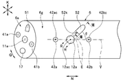
次に、先端部6の構成について、図2~図10を用いて説明する。図2は、図1の先端部を拡大して示す部分斜視図、図3は、図2の先端部に設けられた画像取得部及び他の画像取得部によって取得された被写体像及び他の被写体像を、モニタに表示する構成を概略的に示す図である。
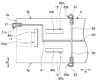
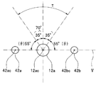
また、図4は、図2の先端部に設けられた画像取得部の対物光学系及び他の画像取得部の対物光学系に流体を供給する各ノズルに連通する管路の構成を概略的に示す図、図5は、図2の先端部の外周側面に設けられるノズルの配置角度を示す図である。
さらに、図6は、図3の表示部の1つの画面内において被写体像と他の被写体像とが隣接して表示される変形例を概略的に示す図、図7は、図3のモニタが複数から構成された変形例を概略的に示す図である。
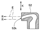
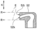
また、図8は、図2中のVIII-VIII線に沿うノズルの断面図、図9は、図8とは異なるノズル開口部の延長線の定義を示す断面図、図10は、図8、図9とは異なるノズル開口部の延長線の定義を示す断面図である。
先ず、先端部6は、後述の各種部材を配置した、挿入部4の長手方向N(長軸方向)に延出する柱状の部分を有する構成部分である。
ここで、柱状とは、円柱や円の一部をカットしたDの字のような形状を長手方向に引き伸ばした形状のほか、多角形柱、錐形の先端部を除去した形状等、各種形状が含まれる。
図2、図3に示すように、挿入部4の先端部6の長手方向Nに交わる方向である径方向Kに位置する外周側面6gに、挿入部4の径方向Kを含むとともに被検体内の所定の領域である第1の領域から、該第1の領域に位置する所定の被写体像である第1の被写体像を取得する所定の被写体像取得部である第1の被写体像取得部12、13の対物光学系である各側方観察用レンズ12a、13aが、挿入部の周方向Qに沿って、略均等な角度、例えば180°間隔で設けられている。
また、図3に示すように、先端部6内において、第1の被写体像取得部12の結像位置に、第1の被写体像取得部12によって取得された第1の被写体像が受光面80bjに結像され光電変換されるよう配置された、CCDまたはCMOS等の撮像部である第1の撮像部80bが設けられている。さらに、第1の被写体像取得部13の結像位置に、第1の被写体像取得部13によって取得された第1の被写体像が受光面80cjに結像され光電変換されるよう配置された、CCDまたはCMOS等の撮像部である第1の撮像部80cが設けられている。
尚、側方観察用レンズ(第1の被写体像取得部)は2つに限定されず、外周側面6gに3つ以上、周方向Qの略均等な角度で設けられていても構わない。
さらに、先端部6の外周側面6gには、第1の被写体像取得部12、13のうちいずれか1つだけ設けられていても構わない。その場合、各側方観察用レンズ12a、13a、撮像部80bまたは80cのうち第1の被写体像取得部に対応する1つだけ設けられることになる。
即ち、第1の被写体像取得部の個数は2個に限定されない。
尚、後述する第2の被写体像取得部11が観察する第2の領域と、第1の被写体像取得部12、13が観察する第1の領域とは、一部が重なっていてもいなくてもよい。
さらに、図2、図3に示すように、挿入部4の先端部6の先端面6sに、該先端面6sよりも前方を含む、第1の領域とは少なくとも一部が異なる他の領域である第2の領域から、該第2の領域に位置する他の被写体像である第2の被写体像を取得する他の被写体像取得部である第2の被写体像取得部11の対物光学系である前方観察用レンズ11aが露出されている。
また、図3に示すように、先端部6内において、第2の被写体像取得部11の結像位置に、第1の撮像部80b、80cとは異なるとともに、第2の被写体像取得部11によって取得された第2の被写体像が受光面80ajに結像され光電変換されるよう配置されたCCDまたはCMOS等の他の撮像部である第2の撮像部80aが設けられている。
つまり、第1の被写体像取得部が観察する第1の領域と、第2の被写体像取得部が観察する第2の領域とでは、例えば互いに光軸が異なる領域である。
つまり、第1の被写体像取得部が観察する第1の領域と、第2の被写体像取得部が観察する第2の領域とでは、例えば互いに光軸が異なる領域である。
図2、図3に示すように、先端部6の外周側面6gにおける側方観察用レンズ12aが設けられた領域において、第1の領域である外周側面6gの側方に照明光を供給する第1の照明部62aが設けられている。
第1の照明部62aは、先端部6の外周側面6gに露出される側方照明用レンズ42aと、表面に側方照明用レンズ42aが被覆された発光素子22aとを具備している。
また、第1の照明部として、外周側面6gに露出される側方照明用レンズ42bと、表面に側方照明用レンズ42bが被覆された発光素子22bとを具備する第1の照明部62bをさらに有していてもよい。
つまり、図2に示すように、外周側面6gにおいて、例えば側方観察用レンズ12aの光軸12acと、側方照明用レンズ42a、42bの各光軸42ac、42bcとが長手方向Nに沿って一直線V上に並ぶことにより、長手方向Nに沿った一直線V上において第1の照明用部62a、62b(側方照明用レンズ42a、42b)で側方観察用レンズ12aを挟むよう、第1の照明部を一対設けてもよい。
さらに、図2、図3に示すように、先端部6の外周側面6gにおける側方観察用レンズ13aが設けられた領域において、第1の領域である外周側面6gの側方に照明光を供給する第1の照明部63aが設けられている。
第1の照明部63aは、先端部6の外周側面6gに露出される側方照明用レンズ43aと、表面に側方照明用レンズ43aが被覆された発光素子23aとを具備している。
また、第1の照明部として、外周側面6gに露出される側方照明用レンズ43bと、表面に側方照明用レンズ43bが被覆された発光素子23bとを具備する第1の照明部63bをさらに有していてもよい。
尚、側方観察用レンズ12aを挟む第1の照明部の個数は2つに限定されず、側方観察用レンズ13aを挟む第1の照明部の個数は2つに限定されない。
また、側方照明用レンズ42a、42bに対して、および側方照明用レンズ43a、43bに対して、光源装置33から図示しないライトガイドを介してそれぞれ照明光を供給しても構わない。
また、図示しないが、外周側面6gにおいて、例えば側方観察用レンズ13aの光軸と、側方照明用レンズ43a、43bの各光軸とが長手方向Nに沿って一直線V上に並ぶことにより、長手方向Nに沿った一直線V上において第1の照明用部63a、63b(側方照明用レンズ43a、43b)で側方観察用レンズ13aを挟むよう、第1の照明部を一対設けてもよい。
図2に示すように、先端部6の先端面6sにおける前方観察用レンズ11aが設けられた領域に、第2の領域、即ち、先端面6sよりも前方に照明光を供給する他の照明部である第2の照明部61aが設けられている。
第2の照明部61aは、先端部6の先端面6sに露出される前方照明用レンズ41aと、表面に前方照明用レンズ41aが被覆された発光素子21aとを具備している。
また、第2の照明部として、先端面6sに露出される前方照明用レンズ41bと、表面に前方照明用レンズ41bが被覆された発光素子21bとを具備する第2の照明部61bをさらに有していてもよい。
尚、第2の照明部の個数は2つに限定されない。また、前方照明用レンズ41a、41bに対して、光源装置33から図示しないライトガイドを介して照明光を供給しても構わない。
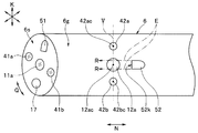
図2、図4に示すように、外周側面6gにおいて、側方観察用レンズ12a及び側方照明用レンズ42a(および42b)が設けられた一直線V上の領域からずれた領域に、側方観察用レンズ12aに対し流体Rを供給するノズル(第1のノズル)52が設けられている。
尚、図4に示すように、ノズル52には、内視鏡2内に設けられた流体供給管路90から分岐した管路92が接続されている。
また、図2に示すように、先端部6の先端面6sには、内視鏡2内に設けられた図示しないチャンネルの先端開口17が形成されているとともに、少なくとも前方観察用レンズ11aに供給口である開口部51kから流体Rを供給するノズル51が設けられている。
尚、図4に示すように、ノズル51には、内視鏡2内に設けられた流体供給管路90から分岐した管路91が接続されている。
さらに、図4に示すように、外周側面6gにおいて、側方観察用レンズ13a及び側方照明用レンズ43a、43bが設けられた一直線V上の領域からずれた領域に、側方観察用レンズ13aに対し流体Rを供給するノズル53が設けられている。
尚、図4に示すように、ノズル53には、内視鏡2内に設けられた流体供給管路90から分岐した管路93が接続されている。
図3に示すように、第1の撮像部80b、80cと第2の撮像部80aは、例えばビデオプロセッサ34内に設けられた画像生成部34aに電気的に接続されている。また、画像生成部34aは、例えばビデオプロセッサ34内に設けられた画像出力部34bに電気的に接続されている。
画像生成部34aは、第1の撮像部80b、80cによって取得された第1の被写体像に基づく画像信号である第1の画像(画像信号)B、Cを生成して画像処理するとともに、第2の撮像部80aによって取得された第2の被写体像に基づく他の画像信号である第2の画像(画像信号)Aを生成して画像処理して、画像出力部34bに出力するものである。
画像出力部34bは、画像生成部34aにより生成された第1の画像信号に基づく第1の画像B、Cおよび第2の画像信号に基づく第2の画像Aとがモニタ36において隣接した位置に表示されるための信号を生成するものである。
具体的には、図3に示すように、画像生成部34a、画像出力部34bにより、モニタ36において、第2の画像Aはモニタ36の中央の画面36aに表示され、各第1の画像B、Cは画面36aの隣り、より具体的には、画面36aの両脇に、画面36aと別個の画面36b、36cにそれぞれ平面的に表示される。
尚、図6に示すように、第1の画像B、C、第2の被写体像Aは、モニタ36の1つの画面内において、第2の被写体像Aがモニタ36の略中央に円形状に表示され、第1の画像B、Cが、第2の画像Aの周囲に略円環状に表示されるよう、隣接して表示されても構わない。
また、上記のように、モニタの1つの画面上に複数の被写体像に基づく画像が表示される形態の他に、モニタが、隣接し合うよう並べて配置される表示部であるモニタ136、236、336として複数から構成され、各画像毎に1つのモニタを対応させて表示させる形態であっても構わない。
つまり図7に示すように、モニタ136に第2の画像Aが表示され、モニタ136とは異なるモニタ236、336に、第1の画像B、Cがそれぞれ第2の画像Aに隣接して表示されても構わない。
尚、以下、ノズル52、53の外周側面6gにおける配置位置を、ノズル52を例に挙げて説明する。
図2に示すように、外周側面6gにおいてノズル52は、長手方向Nに対して設定角度θを有して側方観察用レンズ12aに流体を供給する位置に設けられている。
具体的には、図2に示すように、外周側面6gにおいてノズル52は、一直線V上の領域からずれた領域において、ノズル52の開口部52kの延長線Eが、各側方照明用レンズ42a、42bに重ならない領域において、例えば側方観察用レンズ12aよりも長手方向Nの後方(つまり長手方向Nの基端側、以下、単に後方と称す)に設けられている。
このことにより、開口部52kから側方観察用レンズ12aに前方(長手方向Nの先端側)に向けて液体を供給した際、液体が各側方照明用レンズ42a、42bに付着し難くなる。
尚、開口部52kの延長線Eの定義は、図8に示すように、開口部52kから側方観察用レンズ12aの表面と略平行に流体Rを供給する場合における開口部52kの外径の延長線や、図9に示すように、開口部52kから外周側面6gに向かって斜め下方に流体Rを供給する場合の開口部52kの延長線や、図10に示すように、ノズル52の開口部52kが形成された端面52tの径方向Kの外径全体から側方観察用レンズ12aの表面と略平行に延長された延長線のいずれの場合においても適用可能である。
また、図2、図5に示すように、外周側面6gにおいてノズル52は、一直線V上の領域からずれた領域において、一直線Vに対して設定角度θである前方及び後方に55°傾いた70°の範囲T内に設けられていることが好ましい。このことにより、より確実に開口部52kから供給された液体が各側方照明用レンズ42a、42bに付着し難くなる。尚、以上のことは、外周側面6gに対するノズル53の配置位置においても同様である。
このように、本実施の形態においては、側方観察用レンズ12a、13aに流体Rを供給するノズル52、53は、外周側面6gにおける側方観察用レンズ12a、側方照明用レンズ42a、42bが設けられた一直線V上の領域からずれた領域、外周側面6gにおける側方観察用レンズ13a、側方照明用レンズ43a、43bが設けられた一直線V上の領域からずれた領域にそれぞれ設けられると示した。
このことによれば、各ノズル52、53の供給口である開口部52k、53kから各側方観察用レンズ12a、13aにそれぞれ供給された液体は、側方照明用レンズ42a、42b、43a、43bに供給され難いため、側方照明用レンズ42a、42b、43a、43bに液体が付着し難い。
よって、側方照明用レンズ42a、42b、43a、43bに液体が付着してしまうことによって、第1の領域に照明光を供給した際に発生してしまうハレーションを防止することができる。
特に先端部6の外周側面6gの場合、先端面6sよりも体壁に近いのでより照明光が強く反射してハレーションを起こしやすいことから、側方観察用レンズ12a、13aに対しそれぞれ流体を供給するノズル52、53の配置を工夫することは、先端面6sに配置されるノズル51の配置を工夫することよりも特に有効である。
特に先端部6の外周側面6gの場合、先端面6sよりも体壁に近いのでより照明光が強く反射してハレーションを起こしやすいことから、側方観察用レンズ12a、13aに対しそれぞれ流体を供給するノズル52、53の配置を工夫することは、先端面6sに配置されるノズル51の配置を工夫することよりも特に有効である。
以上から、外周側面6gに設けられた側方観察用レンズ12a、13aに対してノズル52、53から流体Rを供給する際、外周側面6gに設けられた側方照明用レンズ42a、42b、43a、43bに液体が残留し難いことにより、良好な側方視野を確保できる構成を具備する内視鏡2、内視鏡システム1を提供することができる。
尚、以下、変形例を、図11、図12を用いて示す。図11は、図2とは異なるノズルの配置位置を示す先端部の部分斜視図、図12は、図11とは異なるノズルの配置位置を示す先端部の部分斜視図である。
上述した本実施の形態においては、外周側面6gにおいてノズル52は、一直線V上の領域からずれた領域において、一直線Vに対して前方及び後方に55°傾いた70°の範囲T内に設けられていることが好ましいと示した。
よって、図11に示すように、ノズル52は、外周側面6gにおいて、範囲Tにおける一直線Vに対して90°傾いた位置に設けられていても構わない。尚、このことは、ノズル53においても同様である。
また、上述した本実施の形態や図11においては、外周側面6gにおける側方観察用レンズ12aが設けられた領域において、長手方向Nに沿って、側方観察用レンズ12aを一直線V上において挟むよう、一対の側方照明用レンズ42a、42bが設けられていると示した。
これに限らず、図12に示すように、長手方向Nに垂直な方向に沿って、側方観察用レンズ12aを一直線V上において挟むよう、一対の側方照明用レンズ42a、42bが設けられている場合においても上述した本実施の形態や図11の構成は適用可能である。尚、このことは、ノズル53においても同様である。
また、以下、別の変形例を、図13を用いて示す。図13は、図2、図11、図12とは異なるノズルの配置位置を示す先端部の部分斜視図である。
上述した本実施の形態及び図11、図12においては、ノズル52は、側方観察用レンズ12aよりも後方に位置し、側方観察用レンズ12aよりも後方の開口部52kから側方観察用レンズ12aに対して前方に向けて流体Rを供給している場合を例に挙げて示した。
これに限らず、ノズル52は、図13に示すように、長手方向Nにおいて側方観察用レンズ12aよりも前方つまり長手方向Nの先端側に位置し、側方観察用レンズ12aよりも前方つまり長手方向Nの先端側の開口部52kから側方観察用レンズ12aに対して後方つまり長手方向Nの基端側に向けて流体Rを供給しても構わない。
このような構成によれば、上述した本実施の形態及び図11、図12においては、前方に向けてノズル52から流体Rを供給するため、ノズル52から供給された液体や、ノズル52から供給された気体により側方観察用レンズ12aから吹き飛ばされた液体、汚物等が、先端面6sに位置する前方観察用レンズ11aや前方照明用レンズ41a、41bに付着してしまう可能性がある。
しかしながら、図13に示す構成では、ノズル52から側方観察用レンズ12aに向けて後方に流体Rを供給するため、ノズル52からの流体Rの供給に起因して前方観察用レンズ11a、前方観察用レンズ41a、41bに液体や汚物が付着してしまうことを確実に防止することができる。
尚、このことは、ノズル53においても同様である。また、その他の効果は、上述した本実施の形態と同じである。
また、以下、この実施形態の更なる変形例を、図22を用いて示す。図22は、図2、および図11~図13とは異なるノズルの配置位置を示す先端部の部分斜視図である。
図22に示すように、長手方向Nに垂直な方向に沿って、側方観察用レンズ12aを一直線V上において挟むよう、一対の側方照明用レンズ42a、42bが設けられている場合においても、ノズル52が長手方向Nにおいて側方観察用レンズ12aよりも前方に位置し、側方観察用レンズ12aよりも前方の開口部52kから側方観察用レンズ12aに対して後方に向けて流体Rを供給しても構わない。
尚、このことは、ノズル53においても同様である。
また、以下、別の変形例を、図14を用いて示す。図14は、図2、図11~図13とは異なるノズルの配置位置を示す先端部の部分斜視図である。
上述した本実施の形態においては、外周側面6gにおいてノズル52は、一直線V上の領域からずれた領域において、一直線Vに対して前方及び後方に55°傾いた70°の範囲T内に設けられていることが好ましいと示した。
これに限らず、ノズル52は、外周側面6gにおいて一直線V上の領域からずれた領域であれば、範囲T外に設けられていても構わない。
具体的には、図14に示すように、外周側面6gにおいてノズル52は、一直線V上の領域からずれた領域において、例えば側方観察用レンズ12aの後方において、ノズル52の開口部52kの延長線Eが、各側方照明用レンズ42a、42bに一部が重なる領域に設けられていても構わない。
このような構成によれば、ノズル52から供給された液体は、各側方照明用レンズ42a、42bにも一部供給されてしまうため、各側方照明用レンズ42a、42bに液体が残留してしまう可能性があり本実施の形態よりも効果が劣る。
しかしながら、従来の側方観察用レンズ12a、側方照明用レンズ42a、42b、ノズル52が一直線上に位置する構成よりは、各側方照明用レンズ42a、42bに液体が付着し難くなるため、上述した本実施の形態と同様の効果を得ることができる。尚、このことは、ノズル53においても同様である。
また、以下、この実施形態の更なる変形例を、図23を用いて示す。図23は、図2、および図11~図14とは異なるノズルの配置位置を示す先端部の部分斜視図である。
図23に示すように、外周側面6gにおいてノズル52の開口部52kの延長線Eが各側方照明用レンズ42a、42bに一部が重なる領域に設けられている場合においても、ノズル52が長手方向Nにおいて側方観察用レンズ12aよりも前方に位置し、側方観察用レンズ12aよりも前方の開口部52kから側方観察用レンズ12aに対して後方に向けて流体Rを供給しても構わない。
尚、このことは、ノズル53においても同様である。
さらに、以下、別の変形例を、図15を用いて示す。図15は、図2、図11~図14とは異なるノズルの配置位置を示す先端部の部分斜視図である。
上述した本実施の形態及び図11~図14においては、長手方向Nに沿って、側方観察用レンズ12aを一直線V上において挟むよう、第1の領域である外周側面6gの側方に照明光を供給する一対の側方照明用レンズ42a、42bが設けられており、外周側面6gにおいてノズル52は、一直線V上の領域からずれた領域に設けられていると示した。
これに限らず、図15に示すように、側方観察用レンズ12a、側方照明用レンズ42b、ノズル52を長手方向Nに沿った一直線V上の領域に設け、該領域からずれた領域に、側方照明用レンズ42aが設けられていても構わない。
つまり、側方観察用レンズ12aと、2つのうち1つの側方照明用レンズ42aとを結ぶ線からずれてノズルが配置されていても構わない。
このような構成によれば、ノズル52から側方照明用レンズ42bにも液体が供給されてしまうため、側方照明用レンズ42bに液体が付着してしまう。ところが、側方照明用レンズ42bはノズル52に隣接して設けられているため、ノズル52から供給される気体により、側方照明用レンズ42bに付着する液体を確実に除去することができる。
尚、側方照明用レンズ42aには、本実施の形態と同様に、流体Rはノズル52から供給され難いことから、上述した本実施の形態と略同様の効果を得ることができる。また、このことは、ノズル53、側方照明用レンズ43aにおいても同様である。
また、以下、この実施形態の更なる変形例を、図24を用いて示す。図24は、図2、および図11~図15とは異なるノズルの配置位置を示す先端部の部分斜視図である。
図24に示すように、外周側面6gにおいて、側方観察用レンズ12a、側方照明用レンズ42b、ノズル52を長手方向Nに沿った一直線V上の領域に設け、該領域からずれた領域に、側方照明用レンズ42aが設けられている場合においても、ノズル52が長手方向Nにおいて側方観察用レンズ12aよりも前方に位置し、側方観察用レンズ12aよりも前方の開口部52kから側方観察用レンズ12aに対して後方に向けて流体Rを供給しても構わない。
尚、このことは、ノズル53においても同様である。
さらに、以下、別の変形例を、図25を用いて示す。図25は、図2、図11~図24とは異なるノズルの配置位置を示す先端部の部分斜視図である。
図25に示すように、外周側面6gにおいて、側方観察用レンズ12aと、側方照明用レンズ42aとを結ぶ線からずれた領域にノズル52が配置されていれば、一対の側方照明用レンズ42a、42bが、長手方向Nに垂直な方向に沿って側方観察用レンズ12aを一直線V上において挟む、図13及び図22に示すような形態のように設けられていなくてもよい。
つまり、側方照明用レンズは、側方観察用レンズ12aを一直線上において挟む一対ではなく、外周側面6gの1つの側に側方照明用レンズ42aとして1つだけ設けられていてもよい。
尚、この実施形態の場合においても、ノズル52が長手方向Nにおいて側方観察用レンズ12aよりも前方に位置し、側方観察用レンズ12aよりも前方の開口部52kから側方観察用レンズ12aに対して後方に向けて流体Rを供給しても構わない。
尚、このことは、ノズル53においても同様である。
(第2実施の形態)
図16は、本実施の形態の内視鏡における柱状の先端部の外周側面に設けられた側方観察用レンズ、側方照明用レンズ、ノズルを概略的に示す部分断面図である。
図16は、本実施の形態の内視鏡における柱状の先端部の外周側面に設けられた側方観察用レンズ、側方照明用レンズ、ノズルを概略的に示す部分断面図である。
この第2実施の形態の内視鏡、内視鏡システムの構成は、上述した図1~図15に示した第1実施の形態の内視鏡、内視鏡システムと比して、先端部の外周側面に対し、側方照明用レンズが側方観察用レンズよりも径方向において異なる高さの位置に設けられている点が異なる。
よって、この相違点のみを説明し、第1実施の形態と同様の構成には同じ符号を付し、その説明は省略する。
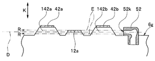
図16に示すように、本実施の形態においては、上述した第1実施の形態の構成に加え、外周側面16gにおいて、側方観察用レンズ12aがノズル52の開口部52kの中心軸の延長線Dに一部が重なって位置している状態において、例えば一対の側方照明用レンズ42a、42bにおける径方向Kの突出量が側方観察用レンズ12aに対して異なっている。
具体的には、一対の側方照明用レンズ42a、42bが、側方観察用レンズ12aよりも各突出部142a、142bにより径方向Kに高く、側方観察用レンズ12aの観察視野に入らない程度に突出して位置している。
尚、このような構成においては、ノズル52から吐出された流体Rは、突出部142bの外周部を伝って側方観察用レンズ12aに供給され、突出部142aの外周部を伝って側方観察用レンズ12aよりも前方に排出される。
このような構成によれば、側方照明用レンズ42a、42bが径方向Kにおいて側方観察用レンズ12aよりも高く位置している。このことにより、ノズル52から供給された液体が側方照明用レンズ42a、42bにより付着し難くなることから、上述した第1実施の形態よりもより確実にハレーションの発生を防ぐことができる。
尚、その他の効果は、上述した第1実施の形態と同じである。また、このことは、ノズル53、側方観察用レンズ13a、例えば一対の側方照明用レンズ43a、43b側においても同様である。
また、側方照明用レンズ42a、42bまたは43a、43bは、一対ではなく、挿入部の外周の例えば左右側面に1つずつ設けられていてもよい。
また、側方照明用レンズ42a、42bまたは43a、43bは、一対ではなく、挿入部の外周の例えば左右側面に1つずつ設けられていてもよい。
尚、以下、変形例を、図17を用いて示す。図17は、図16の突出部の周囲に壁部を設けた変形例を示す図である。
図17に示すように、各突出部142a、142bの周囲においてノズル52に対向する位置に、壁部71、72が設けられていても構わない。尚、壁部71、72も側方観察用レンズ12aの観察視野に入らない程度の高さを径方向Kに有している。
このことによれば、壁部71、72により、確実に、ノズル52から供給された液体が例えば一対の側方照明用レンズ42a、42bに付着し難くなる。尚、その他の構成及び効果は、上述した本実施の形態と同じである。
また、壁部71、72は、ノズル53、側方観察用レンズ13a、側方照明用レンズ43a、43b側においても同様に適用可能である。
また、以下、別の変形例を、図18を用いて示す。図18は、図16の側方照明用レンズを、側方観察用レンズよりも径方向に低く位置させた変形例を概略的に示す部分断面図である。
図18に示すように、本実施の形態とは反対に、例えば一対の側方照明用レンズ42a、42bが、側方観察用レンズ12aよりも径方向Kに低く位置していても構わない。
このような構成によれば、側方照明用レンズ42a、42bが径方向Kにおいて側方観察用レンズ12aよりも低く位置していることにより、ノズル52から供給された液体が一対の側方照明用レンズ42a、42bにより付着し難くなることから、上述した本実施の形態と同様の効果を得ることができる。
尚、その他の効果は、上述した本実施の形態と同じである。また、このことは、ノズル53、側方観察用レンズ13a、側方照明用レンズ43a、43b側においても同様である。
また、側方照明用レンズ42a、42bまたは43a、43bは、一対ではなく、挿入部の外周の例えば左右側面に1つずつ設けられていてもよい。
また、側方照明用レンズ42a、42bまたは43a、43bは、一対ではなく、挿入部の外周の例えば左右側面に1つずつ設けられていてもよい。
(第3実施の形態)
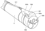
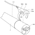
以下、第3実施の形態を、図19、図20、図21を用いて示す。図19は、内視鏡の挿入部に画像取得ユニットが装着された変形例を概略的に示す斜視図、図20は、図19の挿入部から画像取得ユニットが脱却された変形例を概略的に示す斜視図、図21は、内視鏡の挿入部に画像取得ユニットが装着された図19とは異なる変形例を概略的に示す斜視図である。
以下、第3実施の形態を、図19、図20、図21を用いて示す。図19は、内視鏡の挿入部に画像取得ユニットが装着された変形例を概略的に示す斜視図、図20は、図19の挿入部から画像取得ユニットが脱却された変形例を概略的に示す斜視図、図21は、内視鏡の挿入部に画像取得ユニットが装着された図19とは異なる変形例を概略的に示す斜視図である。
この第3実施の形態の内視鏡、内視鏡システムの構成は、上述した図1~図18に示した第1および第2実施の形態の内視鏡、内視鏡システムと比して、前方の被写体像(第2の被写体像)を取得する通常の内視鏡600に対して、画像取得ユニット500を装着することで、左右側方の被写体像(第1の被写体像)を取得することができる内視鏡とした点が異なる。
図19、図20に示すように、前方の他の被写体像(第2の被写体像)を取得する通常の内視鏡600に対して、左右側方の所定の被写体像(第1の被写体像)を取得する被写体像取得部(第1の被写体像取得部)501と、左右側方をそれぞれ照明する照明部(第1の照明部)502a、502bと、第1の被写体像取得部501に流体Rを供給するノズル522とを備える着脱自在な画像取得ユニット500を装着するものにも、上述した第1及び第2実施の形態と同様の構成は適用可能である。
図21に示すように、ノズル522が照明部及び被写体像取得部が設けられた一直線上の領域からずれた領域に設けられていれば、照明部(第1の照明部)は一対でない1つ(502a)だけ設けられていてもよく、また、ノズル522が照明部及び被写体像取得部が設けられた一直線上の領域に対して平行に近い配置で設けられていてもよい。
図21に記載のような上記実施形態の場合、ノズル522に対向する位置に、壁部571が設けられていても構わない。尚、壁部571も被写体像取得部501の観察視野に入らない程度の高さを有している。
このことによれば、壁部571により、ノズル522から供給された液体が確実に被写体像取得部501に誘導されるとともに、照明部502aに付着し難くなる。尚、その他の構成及び効果は、上述した本実施の形態と同じである。
このことによれば、壁部571により、ノズル522から供給された液体が確実に被写体像取得部501に誘導されるとともに、照明部502aに付着し難くなる。尚、その他の構成及び効果は、上述した本実施の形態と同じである。
以上のような実施形態において、外部から画像取得ユニット500に設けたノズル522に対して流体Rを供給するための供給管路を有していることが好ましい。
そのような例の1つとして、画像取得ユニット500と前述のビデオプロセッサ34との間で電力や信号等を授受するケーブル511の内部に、外部から画像取得ユニット500に設けたノズル522に対して流体Rを供給するための供給管路を配置する方法等が考えられる。
そのような例の1つとして、画像取得ユニット500と前述のビデオプロセッサ34との間で電力や信号等を授受するケーブル511の内部に、外部から画像取得ユニット500に設けたノズル522に対して流体Rを供給するための供給管路を配置する方法等が考えられる。
このような構成によれば、前方の被写体像を取得する通常の内視鏡に対して、画像取得ユニットを具備することで、左右側方の被写体像を取得することができる内視鏡であっても、ノズルから供給された液体が側方照明用レンズに対してより付着し難くなる効果を得ることができる。
本発明は、上述した実施の形態に限定されるものではなく、本発明の要旨を変えない範囲において、種々の変更、改変等が可能である。
本出願は、2015年6月1日に日本国に出願された特願2015-111589号を優先権主張の基礎として出願するものであり、上記の内容は、本願明細書、請求の範囲、図面に引用されたものである。
Claims (12)
- 被検体内に挿入される挿入部と、
前記挿入部の柱状の外周側面に設けられるとともに、前記被検体内の所定の領域から被写体像を取得する被写体像取得部と、
前記挿入部の前記外周側面における前記被写体像取得部が設けられた領域において設けられるとともに、前記所定の領域を照明する照明部と、
前記挿入部の前記外周側面における前記照明部及び前記被写体像取得部が設けられた一直線上の領域からずれた領域に設けられるとともに、前記被写体像取得部に対して流体を供給するノズルと、
を具備することを特徴とする内視鏡。 - 前記照明部は、前記被写体像取得部を一直線上に挟むように一対設けられることを特徴とする請求項1に記載の内視鏡。
- 前記ノズルは、前記外周側面において前記被写体像取得部よりも前記挿入部の長手方向の先端側に設けられており、前記長手方向の先端側から前記被写体像取得部に対して前記長手方向の基端側に向けて前記流体を供給することを特徴とする請求項1に記載の内視鏡。
- 前記被写体像取得部の光軸と前記照明部の光軸とが前記挿入部の長手方向に沿った一直線上に位置するよう、前記外周側面に対し、前記被写体像取得部及び前記照明部が位置していることを特徴とする請求項1に記載の内視鏡。
- 前記挿入部の先端面に設けられるとともに、前記先端面よりも前記挿入部の長手方向の前方を含む前記所定の領域とは少なくとも一部が異なる他の領域から他の被写体像を取得する他の被写体像取得部と、
前記先端面における前記他の被写体像取得部が設けられた領域に設けられるとともに、前記他の領域を照明する他の照明部と、
をさらに具備していることを特徴とする請求項1に記載の内視鏡。 - 前記ノズルは、前記外周側面において前記挿入部の長手方向に対して設定角度を有して前記被写体像取得部に前記流体を供給することを特徴とする請求項1に記載の内視鏡。
- 前記被写体像取得部は対物光学系を有しているとともに、前記対物光学系は、前記ノズルの供給口の中心軸の延長線に一部が重なって位置しており、
前記照明部は、前記外周側面において前記挿入部の長手方向に対して交わる方向における径方向の突出量が前記対物光学系に対して異なっていることを特徴とする請求項1に記載の内視鏡。 - 請求項1に記載の前記内視鏡と、
前記被写体像に基づく画像信号を生成する画像信号生成部と、
前記画像信号生成部により生成された前記画像信号が前記被写体像として表示される少なくとも1つの表示部と、
を具備することを特徴とする内視鏡システム。 - 前記挿入部の先端面に設けられるとともに、前記先端面よりも前記挿入部の長手方向の前方を含む前記所定の領域とは少なくとも一部が異なる他の領域から他の被写体像を取得する他の被写体像取得部と、
前記先端面における前記他の被写体像取得部が設けられた領域に設けられるとともに、前記他の領域を照明する他の照明部と、
をさらに具備し、
前記画像信号生成部は、さらに前記他の被写体像に基づく他の画像信号を生成することを特徴とする請求項8に記載の内視鏡システム。 - 前記画像信号生成部は、前記被写体像と前記他の被写体像とが前記表示部における隣接した位置に表示されるように前記画像信号及び前記他の画像信号を生成することを特徴とする請求項9に記載の内視鏡システム。
- 前記表示部は複数から構成されており、
複数の前記表示部の内、前記被写体像と前記他の被写体像とは異なる前記表示部に表示されることを特徴とする請求項9に記載の内視鏡システム。 - 前記被写体像取得部は、前記被写体像を光電変換する撮像部を有し、
前記他の被写体像取得部は、前記他の被写体像を光電変換するとともに前記撮像部とは異なる他の撮像部を有していることを特徴とする請求項9に記載の内視鏡システム。
Priority Applications (1)
| Application Number | Priority Date | Filing Date | Title |
|---|---|---|---|
| JP2017505674A JPWO2016194634A1 (ja) | 2015-06-01 | 2016-05-19 | 内視鏡、内視鏡システム |
Applications Claiming Priority (2)
| Application Number | Priority Date | Filing Date | Title |
|---|---|---|---|
| JP2015-111589 | 2015-06-01 | ||
| JP2015111589 | 2015-06-01 |
Publications (1)
| Publication Number | Publication Date |
|---|---|
| WO2016194634A1 true WO2016194634A1 (ja) | 2016-12-08 |
Family
ID=57442318
Family Applications (1)
| Application Number | Title | Priority Date | Filing Date |
|---|---|---|---|
| PCT/JP2016/064902 Ceased WO2016194634A1 (ja) | 2015-06-01 | 2016-05-19 | 内視鏡、内視鏡システム |
Country Status (2)
| Country | Link |
|---|---|
| JP (1) | JPWO2016194634A1 (ja) |
| WO (1) | WO2016194634A1 (ja) |
Citations (3)
| Publication number | Priority date | Publication date | Assignee | Title |
|---|---|---|---|---|
| JPS63246715A (ja) * | 1987-04-01 | 1988-10-13 | Olympus Optical Co Ltd | 電子内視鏡 |
| JPH05123285A (ja) * | 1991-11-08 | 1993-05-21 | Fuji Photo Optical Co Ltd | 内視鏡先端部のノズル構造 |
| US20140213850A1 (en) * | 2009-06-18 | 2014-07-31 | Endochoice Inc. | Compact Multi-Viewing Element Endoscope System |
Family Cites Families (1)
| Publication number | Priority date | Publication date | Assignee | Title |
|---|---|---|---|---|
| JP3845311B2 (ja) * | 2002-01-21 | 2006-11-15 | オリンパス株式会社 | 内視鏡 |
-
2016
- 2016-05-19 JP JP2017505674A patent/JPWO2016194634A1/ja active Pending
- 2016-05-19 WO PCT/JP2016/064902 patent/WO2016194634A1/ja not_active Ceased
Patent Citations (3)
| Publication number | Priority date | Publication date | Assignee | Title |
|---|---|---|---|---|
| JPS63246715A (ja) * | 1987-04-01 | 1988-10-13 | Olympus Optical Co Ltd | 電子内視鏡 |
| JPH05123285A (ja) * | 1991-11-08 | 1993-05-21 | Fuji Photo Optical Co Ltd | 内視鏡先端部のノズル構造 |
| US20140213850A1 (en) * | 2009-06-18 | 2014-07-31 | Endochoice Inc. | Compact Multi-Viewing Element Endoscope System |
Also Published As
| Publication number | Publication date |
|---|---|
| JPWO2016194634A1 (ja) | 2017-06-15 |
Similar Documents
| Publication | Publication Date | Title |
|---|---|---|
| JP6054874B2 (ja) | マルチカメラ内視鏡用フレキシブル電子回路基板 | |
| EP2618718B1 (en) | Multi-camera endoscope having fluid channels | |
| JP5942044B2 (ja) | 内視鏡システム | |
| JP2011130918A (ja) | 内視鏡装置及びこの内視鏡装置に用いられる光学アダプタ | |
| JP2015533300A (ja) | マルチカメラ内視鏡 | |
| JP2014524819A (ja) | マルチカメラ内視鏡 | |
| US20120232345A1 (en) | Camera assembly for medical probes | |
| JP5583880B1 (ja) | 立体内視鏡 | |
| US20200000320A1 (en) | Endoscope | |
| US20190350449A1 (en) | Endoscope | |
| EP3242584B1 (en) | Tubed manifold of a multiple viewing elements endoscope | |
| US10349814B2 (en) | Endoscope system | |
| CN110996749A (zh) | 3d视频内窥镜 | |
| WO2016194634A1 (ja) | 内視鏡、内視鏡システム | |
| JP4725162B2 (ja) | 超音波内視鏡 | |
| JP5736236B2 (ja) | 内視鏡 | |
| WO2016031280A1 (ja) | 内視鏡と、この内視鏡を備えた内視鏡システム | |
| WO2016185830A1 (ja) | 内視鏡及び内視鏡システム | |
| HK40020574B (en) | 3d video endoscope | |
| HK40020574A (en) | 3d video endoscope |
Legal Events
| Date | Code | Title | Description |
|---|---|---|---|
| 121 | Ep: the epo has been informed by wipo that ep was designated in this application |
Ref document number: 16803069 Country of ref document: EP Kind code of ref document: A1 |
|
| ENP | Entry into the national phase |
Ref document number: 2017505674 Country of ref document: JP Kind code of ref document: A |
|
| NENP | Non-entry into the national phase |
Ref country code: DE |
|
| 122 | Ep: pct application non-entry in european phase |
Ref document number: 16803069 Country of ref document: EP Kind code of ref document: A1 |