WO2016190285A1 - リハビリテーションシステム、リハビリテーション用プログラム、及び、リハビリテーション方法 - Google Patents
リハビリテーションシステム、リハビリテーション用プログラム、及び、リハビリテーション方法 Download PDFInfo
- Publication number
- WO2016190285A1 WO2016190285A1 PCT/JP2016/065226 JP2016065226W WO2016190285A1 WO 2016190285 A1 WO2016190285 A1 WO 2016190285A1 JP 2016065226 W JP2016065226 W JP 2016065226W WO 2016190285 A1 WO2016190285 A1 WO 2016190285A1
- Authority
- WO
- WIPO (PCT)
- Prior art keywords
- patient
- rehabilitation
- display
- image
- unit
- Prior art date
Links
- 238000000034 method Methods 0.000 title claims abstract description 70
- 230000001939 inductive effect Effects 0.000 claims abstract description 12
- 238000003384 imaging method Methods 0.000 claims description 51
- 210000000245 forearm Anatomy 0.000 claims description 45
- 210000000707 wrist Anatomy 0.000 claims description 26
- 230000000007 visual effect Effects 0.000 claims description 24
- 238000001514 detection method Methods 0.000 claims description 12
- 238000001454 recorded image Methods 0.000 claims description 12
- 230000021542 voluntary musculoskeletal movement Effects 0.000 claims description 12
- 230000000694 effects Effects 0.000 abstract description 11
- 230000008569 process Effects 0.000 description 48
- 238000012545 processing Methods 0.000 description 29
- 230000001953 sensory effect Effects 0.000 description 12
- 230000006870 function Effects 0.000 description 9
- 230000000638 stimulation Effects 0.000 description 8
- 208000002193 Pain Diseases 0.000 description 5
- 230000008859 change Effects 0.000 description 5
- 239000000126 substance Substances 0.000 description 5
- 208000027418 Wounds and injury Diseases 0.000 description 4
- 230000007177 brain activity Effects 0.000 description 4
- 230000003183 myoelectrical effect Effects 0.000 description 4
- 229920000742 Cotton Polymers 0.000 description 3
- 210000004556 brain Anatomy 0.000 description 3
- 238000010586 diagram Methods 0.000 description 3
- 210000003414 extremity Anatomy 0.000 description 3
- 230000002159 abnormal effect Effects 0.000 description 2
- 230000004308 accommodation Effects 0.000 description 2
- 230000009471 action Effects 0.000 description 2
- 230000003727 cerebral blood flow Effects 0.000 description 2
- 230000006378 damage Effects 0.000 description 2
- 208000014674 injury Diseases 0.000 description 2
- 210000003205 muscle Anatomy 0.000 description 2
- 230000008929 regeneration Effects 0.000 description 2
- 238000011069 regeneration method Methods 0.000 description 2
- 230000035807 sensation Effects 0.000 description 2
- 230000001360 synchronised effect Effects 0.000 description 2
- 230000007704 transition Effects 0.000 description 2
- 206010019468 Hemiplegia Diseases 0.000 description 1
- 125000002066 L-histidyl group Chemical group [H]N1C([H])=NC(C([H])([H])[C@](C(=O)[*])([H])N([H])[H])=C1[H] 0.000 description 1
- 206010033799 Paralysis Diseases 0.000 description 1
- 208000004983 Phantom Limb Diseases 0.000 description 1
- 206010056238 Phantom pain Diseases 0.000 description 1
- 230000036982 action potential Effects 0.000 description 1
- 230000004913 activation Effects 0.000 description 1
- 238000002266 amputation Methods 0.000 description 1
- 230000017531 blood circulation Effects 0.000 description 1
- 238000012790 confirmation Methods 0.000 description 1
- 230000000994 depressogenic effect Effects 0.000 description 1
- 230000002401 inhibitory effect Effects 0.000 description 1
- 238000007689 inspection Methods 0.000 description 1
- 230000009191 jumping Effects 0.000 description 1
- 239000000463 material Substances 0.000 description 1
- 230000007659 motor function Effects 0.000 description 1
- 230000001537 neural effect Effects 0.000 description 1
- 230000001737 promoting effect Effects 0.000 description 1
- 238000011084 recovery Methods 0.000 description 1
- 230000000284 resting effect Effects 0.000 description 1
- 210000004761 scalp Anatomy 0.000 description 1
- 210000001991 scapula Anatomy 0.000 description 1
- 230000001629 suppression Effects 0.000 description 1
- 238000012360 testing method Methods 0.000 description 1
- 238000012549 training Methods 0.000 description 1
- 230000001960 triggered effect Effects 0.000 description 1
- 210000002268 wool Anatomy 0.000 description 1
Images


Classifications
-
- A—HUMAN NECESSITIES
- A61—MEDICAL OR VETERINARY SCIENCE; HYGIENE
- A61H—PHYSICAL THERAPY APPARATUS, e.g. DEVICES FOR LOCATING OR STIMULATING REFLEX POINTS IN THE BODY; ARTIFICIAL RESPIRATION; MASSAGE; BATHING DEVICES FOR SPECIAL THERAPEUTIC OR HYGIENIC PURPOSES OR SPECIFIC PARTS OF THE BODY
- A61H1/00—Apparatus for passive exercising; Vibrating apparatus; Chiropractic devices, e.g. body impacting devices, external devices for briefly extending or aligning unbroken bones
- A61H1/02—Stretching or bending or torsioning apparatus for exercising
Definitions
- the present invention relates to a rehabilitation system, a rehabilitation program, and a rehabilitation method used for rehabilitation of a patient having a rehabilitation target site in which voluntary movement is difficult or impossible due to the patient's own will.
- the rehabilitation device described in Patent Document 1 detects a visual stimulation device that shows normal movement of a paralyzed body part to a patient, a body driving device that drives the body, and a means that detects a biological signal of the patient. Means for generating data for driving the body from the biological signal and means for transmitting the generated data to the body drive device.
- the rehabilitation device by the control based on the program forces the patient to perform the same movement as the movement of the body part that the body driving device shows to the patient in cooperation with the visual stimulation device by using the detection of the biological signal or the external signal as a trigger. And operate to continue the movement for a certain period of time.
- the present invention is a rehabilitation system capable of obtaining a high rehabilitation effect by inducing a self-motion illusion that a person's body is exercising even for a patient who cannot express his intention to move the body spontaneously.
- An object of the present invention is to provide a rehabilitation program and a rehabilitation method.
- the present invention is a rehabilitation system for use in rehabilitation of a patient having a rehabilitation target part in which voluntary movement is difficult or impossible due to the patient's own will, and can display the rehabilitation target part of the patient from the patient's eyes
- a control unit that controls the display unit so as to display on the display unit in a positional relationship overlapping with the rehabilitation target site of the patient as viewed from the patient, and the control unit directly controls the patient.
- control unit controls the display unit so that the image of the corresponding part displayed on the display unit is alternately switched between a moving state and a stationary state. It is preferable.
- an imaging device capable of imaging a patient's part
- the control unit images the other part when the patient's rehabilitation target part is one part paired on the left and right sides of the patient's body. And controlling the display unit so that an image obtained by reversing the captured image of the other part is displayed on the display unit as the image of the corresponding part. It is preferable to carry out.
- control unit controls the imaging apparatus so that imaging start and imaging end by the imaging apparatus are performed based on the operation of the corresponding part.
- control unit switches the display unit to display the real image captured by the imaging device and the recorded image captured and recorded by the imaging device.
- the equivalent portion is continuously transferred from the video of the corresponding portion in the real image to the video of the corresponding portion in the recorded image by an overlay function. It is preferable to control the display unit so that a smooth transition is displayed.
- it may have a target part storage space for storing the rehabilitation target part of the patient so that the distance from the display part to the patient's rehabilitation target part is shorter than the distance from the display part to the patient's eyes.
- the said imaging device images the said equivalent site
- a covering member that covers at least the patient and the display unit and constitutes a dark place that accommodates at least the patient and the display unit.
- the rehabilitation target site of the patient is a part of the hand from the wrist and includes a forearm support member that supports the forearm from the elbow to the wrist of the patient, and the forearm support member is supported by the forearm support member. It is preferable that the forearm support member can be rotated about the portion of the forearm support member facing the portion of the hand from the wrist when the is supported.
- the display surface of the display unit is inclined so as to go upward as it moves away from the patient toward the front of the patient.
- the display surface of the said display part inclines so that it may go upward along each of left direction and right direction centering on a sagittal surface of a patient.
- the display surface of the display unit has a positional relationship that is a position in front of the patient and rotated in parallel in the horizontal direction around the position on the sagittal plane of the patient.
- the body drive unit includes a body drive unit that forcibly moves a rehabilitation target site of a patient, and the control unit drives the body drive unit in synchronization with the corresponding site displayed on the display unit. It is preferable to control the above.
- a body driving unit that forcibly moves a patient's rehabilitation target site, a biological signal acquisition unit that acquires a biological signal from the patient, and a characteristic biological signal that indicates a state in which the self-motion illusion is induced It is preferable that the control unit controls the body driving unit so that the body driving unit is driven when the characteristic biological signal is detected.
- control unit controls the body driving unit so that the body driving unit is driven when the characteristic biological signal is detected, and the corresponding portion displayed on the display unit It is preferable to control the display unit so that the image of the image moves in synchronization with the body drive unit.
- the present invention provides a rehabilitation program for use in rehabilitation of a patient having a rehabilitation target site in which voluntary movement according to the patient's own will becomes difficult or impossible, and the patient's rehabilitation target site is in motion
- the patient's rehabilitation target part can be shielded against the patient's eyes from the moving image of the corresponding part corresponding to the patient's rehabilitation target part.
- the display unit displays the positional relationship overlapping the rehabilitation target site of the patient as viewed from the patient, and the patient is more than the apparent size of the rehabilitation target site of the patient when the patient directly views the rehabilitation target site of the patient.
- the visual size of the image of the corresponding part is larger than the patient.
- related rehabilitation program for causing a computer to function.
- the present invention also relates to a rehabilitation method for use in rehabilitation of a patient having a rehabilitation target site in which voluntary movement is difficult or impossible due to the patient's own will, and the patient's rehabilitation target site is in motion
- the image showing the movement of the corresponding part corresponding to the rehabilitation target part of the patient can be shielded from the patient's eyes.
- the equivalent part when the patient sees the video of the equivalent part displayed on the display part rather than the apparent size of the rehabilitation target part Towards the size of appearance of images, to appear larger when viewed from the patient, to display the image of the corresponding region on the display unit, it has a considerable image enlargement display step of sites related rehabilitation methods.
- a high rehabilitation effect can be obtained by inducing a self-motion illusion that a person's body is exercising even for a patient who cannot express his intention to move the body spontaneously.
- a rehabilitation system, a rehabilitation program, and a rehabilitation method can be provided.
- FIG. 1 is a block diagram showing a rehabilitation system 1 according to a first embodiment of the present invention. It is a flowchart which shows the control by the control part 30 at the time of starting of the rehabilitation system 1 by the program for rehabilitation by 1st Embodiment of this invention. It is a flowchart which shows the control by the control part 30 in the video recording reproduction
- the rehabilitation system 1 is a rehabilitation system used for rehabilitation of a patient having a rehabilitation target site in which voluntary movement according to the patient's own will becomes difficult or impossible.
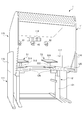
- a control unit 30 As shown in FIGS.
- the mounting table 12 is composed of a table having leg portions 121 and an upper plate 125.
- the leg part 121 has an electric actuator (not shown), and when the electric actuator is driven, the leg part 121 expands and contracts in the vertical direction, whereby the height of the upper plate 125 can be adjusted.
- the upper plate 125 is fixed to the upper end portion of the leg portion 121.
- the upper plate 125 has a substantially rectangular shape, and the central portion of one of the pair of long sides has a cutout portion 126 that is recessed in a semicircular shape toward the center of the upper plate 125. Yes.
- one long side of the upper plate 125 having the notch 126 is arranged on the near side, and the other long side of the upper plate 125 having the notch 126 is on the back side.
- a position of a patient who is placed and seated on a chair, wheelchair or the like is located in the semicircular cutout portion 126 and is directed from the near side of the mounting table 12 to the back side (hereinafter referred to as “use position”).
- the mounting table 12 is used by the patient.
- the covering member 11 has a lower part 111 surrounding the mounting table 12 and an upper part 115 covering the upper side of the mounting table 12.
- the lower part 111 is comprised by the plate-shaped member, and is comprised so that the back
- the upper part 115 is configured to cover the entire space above the mounting table 12. Therefore, the covering member 11 is opened on the front side of the rehabilitation system 1 when viewed from the patient using the rehabilitation system 1. With this configuration, the covering member 11 covers a patient and a left display 51 and a right display 52 as display units to be described later, and constitutes a dark place that houses the left display 51 and the right display 52 as patients and a display unit.
- the left and right sides of the covering member 11 have windows 116.
- the window 116 is slidable in the back direction or the near side when viewed from the patient, and is configured such that the window 116 is opened by sliding in the near direction, and the window 116 is closed by sliding in the far direction. .
- the operator or therapist can visually confirm that the patient or the therapist is rehabilitating the patient covered by the covering member 11 through the through-hole 117.
- a vent hole 118 is formed at the upper end portion of the back wall portion constituting the upper portion 115 of the covering member 11.
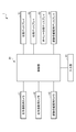
- the left display 51, the right display 52, the operator display 53, the subject observation display 54, the left hand photographing camera 41, the right hand photographing camera 42, the subject observation camera 43, and the input unit 61 are electrically connected to the control unit 30. It is connected to the.
- the left-hand shooting camera 41, the right-hand shooting camera 42, and the subject observation camera 43 are composed of a CCD camera or the like.
- the left-hand photographing camera 41 is fixed to the upper part inside the covering member 11 located above the left hand of the patient in the use position so that the left hand of the patient in the use position can be photographed.
- the right hand photographing camera 42 is fixed to the upper part inside the covering member 11 located above the right hand of the patient in the use position so that the right hand of the patient in the use position can be photographed.
- the subject observation camera 43 is fixed to an upper part inside the cover member 11 located above the patient in the use position so that the state of the patient in the use position can be photographed.
- the input unit 61 includes a keyboard, a mouse, a touch panel, etc. (not shown).
- the input unit 61 is installed outside the covering member 11.
- the touch panel constituting the input unit 61 is provided on the operator display 53. Based on the input from the input unit 61, various settings in the control unit 30 can be performed.
- the operator display 53 and the subject observation display 54 are installed outside the covering member 11 in the same manner as a keyboard and mouse constituting the input unit 61 and a computer constituting the control unit 30 described later.
- the operator display 53 displays a set value or the like based on an input from the input unit 61 to the control unit 30.
- the subject observation display 54 displays the state of the patient as the subject photographed by the subject observation camera 43.
- the left display 51 has a left display unit 511 and a left monitor arm 512.
- the right display 52 includes a right display unit 521 and a right monitor arm 522.
- the left display unit 511 is supported by the left monitor arm 512 mounted on the upper plate 125 of the mounting table 12.
- the right display unit 521 is supported by the right monitor arm 522 mounted on the upper plate 125 of the mounting table 12. Therefore, a space for inserting the patient's left hand is formed between the left display unit 511 and the upper plate 125 of the mounting table 12.
- a space for inserting the right hand of the patient is formed between the right display unit 521 and the upper plate 125 of the mounting table 12.
- the left display 51 is used when the patient's rehabilitation target site is the left hand
- the right display 52 is used when the patient's rehabilitation target site is the right hand.
- the left display 51 is inserted by inserting the left hand into the space between the left display unit 511 and the upper plate 125 of the mounting table 12 as shown in FIG. Shields the left hand, which is a rehabilitation target site of the patient, from the patient's eyes.
- the photographed patient's right hand is reversed left and right, and enlarged and displayed at a set magnification.
- the left arm LA is directly observed by the patient's eyes.
- the right display 52 is inserted into the patient's eyes by inserting the right hand into the space between the right display unit 521 and the upper plate 125 of the mounting table 12.
- the right hand which is the rehabilitation target site of the patient, is shielded.
- the photographed patient's left hand is reversed left and right, and enlarged and displayed at the set magnification.
- the control unit 30 is configured by a computer having an arithmetic processing unit such as a CPU and a storage unit.
- the control unit 30 is installed outside the covering member 11 and includes a ROM (Read Only Memory), a RAM (Random Access Memory), a flash memory, and the like, and the rehabilitation program includes various data and programs. It is remembered with.
- the rehabilitation program for example, as described above, the right hand of the patient who has been photographed is displayed on the left display 51 so as to be reversed horizontally, or the left hand of the patient who has been photographed is displayed on the right display 52.
- the control unit 30 controls the left display 51, the right display 52, and the like so that the left and right images are reversed.
- the rehabilitation program and the rehabilitation method will be described based on the control by the control unit 30 when the rehabilitation program is executed. Since the control of the control unit 30 for the left display 51 and the control of the control unit 30 for the right display 52 are the same except that the display and the like are symmetrical, the control of the control unit 30 for the left display 51 will be described below. A description of the control of the control unit 30 for the right display 52 will be omitted. Similarly, about a patient, the case where a patient's rehabilitation site
- the control unit 30 By executing the rehabilitation program, the control unit 30 provides the patient with a visual stimulus for inducing a self-motion illusion that the patient's left hand as a rehabilitation target part is moving.
- the left side display 51 As shown in the left side display 51 as a display unit in a positional relationship overlapping the left hand, which is the rehabilitation target part of the patient as viewed from the patient, the image of the right hand as the corresponding part corresponding to the rehabilitation target part is displayed.
- the left display 51 is controlled.
- the control unit 30 displays the equivalent part displayed on the left display 51 as the display unit rather than the size of the patient's left hand.
- “perform control for displaying the left side display 51” means not only the case where the left display 51 is controlled so that the left display 51 is displayed, but also a wide left side. Data is output from the control unit to the left display 51 so that is displayed on the display 51, and is displayed as it is on the left display 51. As a result, is displayed on the left display 51. It means to include even cases.
- the rehabilitation system 1 performs patient rehabilitation by being operated by an operator.
- the control unit 30 controls the operator display 53 to display a display for prompting the operator to select a device on the operator display 53.
- the patient's rehabilitation target site is the left hand
- input that the device for rehabilitation of the left hand is selected
- the patient's rehabilitation target site is the right hand
- the right hand rehabilitation is performed. Enter that you want to select a device for use.
- the process by the control unit 30 proceeds to step S2.
- step S ⁇ b> 2 the control unit 30 controls the operator display 53 to display a display for prompting confirmation of the device set in step 1 on the operator display 53. If the input from the input unit 61 by the operator indicates that the device setting is OK (YES), the processing by the control unit 30 proceeds to step S3. If the input from the input unit 61 by the operator indicates that the device setting is not OK and the setting is canceled (NO), the processing by the control unit 30 proceeds to a flow (FIG. 7) for ending the system.
- step S3 the control unit 30 controls the operator display 53 to display a display for prompting the operator to select a camera and a display on the operator display 53.
- the control unit 30 controls the operator display 53 to display on the operator display 53 a display prompting the user to select a camera to be used from the left hand photographing camera 41 and the right hand photographing camera 42. Do it.
- the control unit 30 controls the operator display 53 to display a display for prompting selection of a display to be used from the left display 51 and the right display 52 on the operator display 53. And the process by the control part 30 progresses to step S4.
- step S ⁇ b> 4 the control unit 30 prompts the user to select an area including the entire right hand on the operator display 53 with respect to the patient's right hand photographed by the right hand photographing camera 42 and displayed on the operator display 53.
- Control for displaying the display on the operator display 53 is performed on the operator display 53.
- the control unit is configured to display the rectangle on the operator display 53 so that the rectangle 515 (see FIG. 8) includes the entire right hand of the patient by the operation of the mouse constituting the input unit 61 by the operator. 30 controls the operator display 53. Then, the process by the control unit 30 proceeds to step S5.
- step S5 the control unit 30 controls the operator display 53 to display a display for prompting adjustment of the camera and video on the operator display 53. Specifically, the selection of whether or not the image captured by the camera is reversed left and right, and the input of an enlarged numerical value (%) for how much the image captured by the camera is enlarged and displayed on the left display 51 Select whether to set the camera exposure, focus, white balance, brightness, contrast, saturation, brightness, etc. automatically or manually, and set each value when these settings are manually selected.
- the operator display 53 is controlled to display on the operator display 53 a display prompting input, color tone (RGB) value input, or the like.
- the operator sets these items by operating a keyboard, a mouse, and a touch panel constituting the input unit 61. And the process by the control part 30 progresses to step S6.
- step S6 the control unit 30 controls the operator display 53 to display on the operator display 53 a prompt for selecting whether to perform recording / reproduction processing or library reproduction during the rehabilitation of the patient.
- the operator selects whether to perform recording / playback processing or library playback processing by operating a mouse or a touch panel constituting the input unit 61 on the operator display 53. If the input from the input unit 61 by the operator is a selection to perform the recording / reproducing process (YES), the process by the control unit 30 proceeds to the recording / reproducing process flow (FIG. 5). If the input from the input unit 61 by the operator is a selection to perform library reproduction processing (NO), the processing by the control unit 30 proceeds to the library reproduction processing flow (FIG. 6).
- the control unit 30 performs a series of controls for causing the left display 51 to display an image captured by the right-handed camera 42. Specifically, first, in step S ⁇ b> 11, the control unit 30 performs control for the operator display 53 to display a display for prompting the setting of the recording condition on the operator display 53. Specifically, on the operator display 53, the recording tact value for setting the buzzer sounding period during recording, the setting of the number of times of recording, and the selection of whether to create a library file are input. This is performed by operating a mouse or a touch panel constituting the unit 61. And the process by the control part 30 progresses to step S12.
- step S12 the control unit 30 displays a display prompting the operator to select whether or not to use the motion of the right hand that is a corresponding part corresponding to the left hand that is a rehabilitation target part of the patient as a trigger for starting and ending recording.
- Control for displaying on the operator is performed on the operator display 53.
- the action of the right hand which is a corresponding part corresponding to the left hand, which is the rehabilitation target part of the patient, is used to automatically start and stop recording video (video) from image recognition. It will be.
- the operator selects whether or not to use the movement of the right hand as a trigger.
- step S13 If the input from the input unit 61 by the operator is a selection to use the right hand action as a trigger (YES), the process by the control unit 30 proceeds to step S13.
- the process by the control unit 30 proceeds to step S15.
- step S13 the control unit 30 displays a display for prompting the operator to set a motion detection value for using the motion of the right hand corresponding to the left hand corresponding to the rehabilitation target region of the patient as a trigger for starting and ending recording. Control to be displayed on the display 53 is performed on the operator display 53.
- a start determination threshold value (%) that is a threshold value setting for the rate of change between the image one frame before and the current image in the operation start detection at the time of shooting by the right-hand shooting camera 42
- the number of times of start determination which is a value for how many times the start is continued, and the rate of change between the image one frame before and the current image in detection of operation stop at the time of shooting with the right-handed shooting camera 42
- settings such as a stop determination threshold (%), which is a threshold setting, and the number of times of stop determination, which is a value regarding how many times the threshold is continuously exceeded, are set on the input unit 61. This is done by operating the mouse and touch panel that make up the. Then, the process by the control unit 30 proceeds to step S14.
- step S14 the control unit 30 controls the operator display 53 to display on the operator display 53 a display for prompting the setting of the overlay. Specifically, whether or not to use the overlay function, the transparency resolution value that sets the change value of the transparency processing loop of the overlay process when using the overlay function, and the transparency of the overlay process
- the time resolution value for setting the processing loop timer setting value and the like are set on the operator display 53 by operating a mouse and a touch panel constituting the input unit 61. And the process by the control part 30 progresses to step S15.
- step S15 the control unit 30 controls the operator display 53 to display on the operator display 53 a display for prompting input of the patient ID and the operation name (file name) of the image to be recorded. Specifically, a patient ID and an operation name (file name) of an image to be recorded are input by operating a mouse, a keyboard, or a touch panel constituting the input unit 61. And the process by the control part 30 progresses to step S16.
- step S16 the control unit 30 controls the operator display 53 to display on the operator display 53 a display prompting the user to input the number of times of recording. Specifically, the number of times of recording to be performed once from the start of recording to the stop of recording is input by operating a mouse, a keyboard, or a touch panel constituting the input unit 61. Then, the process by the control unit 30 proceeds to step S17.
- step S17 the control unit 30 controls the right-handed camera 42 so as to perform recording based on various settings for the recording set in steps S11 to S16.
- the rehabilitation target part of the patient is the left hand that is one part of the patient's body that is paired on the left and right, and the right hand that is the other part is imaged.
- the control unit 30 starts imaging by the right-hand imaging camera 42 as the imaging device based on the start of the right-hand imaging operation as a corresponding part, and starts and ends imaging by the right-hand imaging camera 42. Control is performed on the right-handed camera 42 as is done by stopping.
- the start of imaging is performed using the motion determination data of the video captured by the right-hand shooting camera 42 as a trigger for starting recording based on whether or not the start determination threshold set in step S13 is exceeded.
- control is performed on the right-hand shooting camera 42, and control is performed on the right-hand shooting camera 42 so as to end the imaging as a trigger for ending the recording based on whether or not the stop determination threshold is exceeded. I do. Then, the process by the control unit 30 proceeds to step S18.
- step S18 the control unit 30 performs control to binarize the video obtained in step S17 and acquire a real video. Then, the process by the control unit 30 proceeds to step S19.
- step S19 the control unit 30 controls the left display 51 to display the real image obtained in step 18 on the left display 51. That is, in the rehabilitation method, a video display step of the right hand RH that is a corresponding part is performed. Specifically, as shown in FIG. 8, the control unit 30 displays, as an image of the corresponding part, an image obtained by horizontally inverting the image of the right hand RH as the other imaged part on the left side of the left display 51 as a display unit. Displayed on the display unit 511. The image of the right hand RH that is reversed left and right displayed on the left display 51 is displayed on the left display 51 in a positional relationship overlapping with the left hand inserted below the left display 51 when viewed from the patient.
- the display is performed on the left display unit 511 of the left display 51 as if the left hand of the patient is visible at the tip of the patient's left arm LA. Furthermore, the image of the right hand RH that is reversed left and right displayed on the left display 51 is enlarged and displayed so as to be enlarged about 1.2 times with respect to the patient's left hand when viewed from the patient. That is, the image enlargement display step of the corresponding part in the rehabilitation method is performed.
- Magnification is not fixed at 1.2 times but is variable between 1 and 2 times, for example, about 1.1 to 1.4 times is preferable. This is because if the ratio is smaller than 1.1 times, the image is too small and a visual stimulus for inducing a self-motion illusion in the patient cannot be effectively given to the patient. On the other hand, if the ratio is larger than 1.4 times, the image is too large, and the visual stimulus for inducing the self-motion illusion in the patient cannot be effectively given to the patient.
- control unit 30 alternately switches the right-hand image reversed left and right displayed on the left display 51 as a display unit between a moving state and a stationary state at random timing.
- the left display 51 is controlled. Specifically, for example, the moving image of the right hand RH that is reversed left and right is recorded from the real image that is the image of the right hand that is reversed left and right in a stationary state. Switch to recorded image at random timing.
- the overlay function displays on the left display 51 so that the right hand RH continuously and smoothly transitions from the video of the right hand RH, which is a corresponding part in the real image, to the video of the right hand RH, which is a corresponding part in the recorded image.
- the control unit 30 controls the left display 51.
- “transitioning smoothly and smoothly” means, for example, that the transparency of the right hand RH, which is a corresponding part in the real image, gradually increases, and after becoming transparent to some extent, the skin color of the right hand RH is changed again.
- an overlay is shown in which, when approaching and returning to the skin color of the right hand RH, the video of the right hand RH in the recorded image is displayed.
- the patient who sees the image of the right hand RH that is reversed left and right displayed on the left display 51 is induced to have a so-called self-motion illusion that the body is exercising, and rehabilitation is performed. And the process by the control part 30 progresses to step S20.
- step S20 the control unit 30 determines whether or not recording has been performed for the number of times set in step S16. If the number of times of recording set in step S16 has been performed (YES), the process by the control unit 30 proceeds to step S21. If the number of times set in step S16 has not been recorded (NO), the process by the control unit 30 returns to step S17.
- step S21 the control unit 30 determines whether or not there is an input from the input unit 61 to stop the video reproduction process. If there is an input from the input unit 61 indicating that the video playback process should be stopped (YES), the process proceeds to the system end flow (FIG. 7). If there is no input from the input unit 61 indicating that the video playback process should be stopped (NO), the process by the control unit 30 returns to step S18.
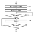
- step S ⁇ b> 31 the control unit 30 controls the operator display 53 to display on the operator display 53 a display that prompts the user to set playback programming.
- the input unit 61 is configured on the operator display 53 such as setting for performing file reproduction, setting of a path in which the file to be reproduced is stored in advance, setting of reproduction time for reproducing the file, and the like. This is done by operating a mouse or touch panel. And the process by the control part 30 progresses to step S32.
- step S32 the control unit 30 controls the operator display 53 to display a display for prompting the setting of the overlay on the operator display 53. Specifically, whether or not to use the overlay function, the transparency resolution value that sets the change value of the transparency processing loop of the overlay process when using the overlay function, and the transparency of the overlay process The time resolution value for setting the processing loop timer setting value and the like are set on the operator display 53 by operating a mouse and a touch panel constituting the input unit 61. Then, the process by the control unit 30 proceeds to step S33.
- step S33 the control unit 30 determines whether or not there is an input from the input unit 61 to start playback of the video. If there is an input from the input unit 61 indicating that the video reproduction process should be started (YES), the process by the control unit 30 proceeds to step S34. If there is no input from the input unit 61 to start the video reproduction process (NO), the process by the control unit 30 returns to step S33.
- step S ⁇ b> 34 the control unit 30 controls the left display 51 to display the video of the file stored in advance in the storage device of the control unit 30 on the left display 51. That is, in the rehabilitation method, a video display step of the right hand RH that is a corresponding part is performed.
- the control unit 30 corresponds to, for example, a video that is stored in a file stored in advance in the storage device of the control unit 30 and that is obtained by horizontally inverting the captured image of the right hand as the other part. The image of the part is displayed on the left display 51 as a display unit. As shown in FIG.
- the right-hand image of the right-hand side image displayed on the left-side display 51 is reversed and overlapped with the left-hand inserted below the left-side display 51 as seen from the patient. It is displayed on the left display 51 in a positional relationship. Furthermore, the image of the right hand RH that is reversed left and right displayed on the left display 51 is enlarged and displayed so as to be enlarged about 1.2 times with respect to the patient's left hand when viewed from the patient. That is, the image enlargement display step of the corresponding part in the rehabilitation method is performed.
- the enlargement ratio is not fixed at 1.2 times, but is variable between 1 and 2 times, similar to the reproduction processing by the control unit 30 in step S19 of the recording / reproduction processing flow.
- control unit 30 moves the video of the right hand that is reversed left and right displayed on the left display 51 as the display unit in a moving state. Control is performed on the left display 51 so as to alternately switch at a random timing in a stationary state. The patient who sees the image of the right hand that is reversed left and right displayed on the left display 51 induces a so-called self-motion illusion that the body is exercising and performs rehabilitation. And the process by the control part 30 progresses to step S35.
- step S35 the control unit 30 determines whether or not there is an input from the input unit 61 to stop the video reproduction process. If there is an input from the input unit 61 indicating that the video playback process should be stopped (YES), the process proceeds to the system end flow (FIG. 7). If there is no input from the input unit 61 indicating that the video playback process should be stopped (NO), the process by the control unit 30 returns to step S34.
- step S51 the control unit 30 determines whether or not there is an input from the input unit 61 indicating that the system should be terminated. If there is an input from the input unit 61 indicating that the system should be terminated (YES), the processing by the control unit 30 proceeds to step S52. If there is no input indicating that the system should be terminated from the input unit 61 (NO), the processing by the control unit 30 proceeds to step S54.
- step S52 the control unit 30 performs a process of controlling and disconnecting the connected right hand camera 42 from the control unit 30 on the right hand camera 42. Then, the process by the control unit 30 proceeds to step S53. In step S53, the control unit 30 performs a process of turning off the system. And the process by the control part 30 is complete
- step S54 the control unit 30 determines whether or not there is an input indicating that the right-hand shooting camera 42 or the video should be adjusted.
- the processing by the control unit 30 is controlled by the control unit 30 at the time of activation (FIG. 4). The process proceeds to step S5. If there is no input from the input unit 61 indicating that the right-hand shooting camera 42 or video should be adjusted (NO), the processing by the control unit 30 proceeds to step S55.
- step S55 the control unit 30 determines whether or not there is an input indicating that recording and reproduction should be performed again. If there is an input from the input unit 61 indicating that recording / playback should be performed (YES), the processing by the control unit 30 proceeds to step S11 of the recording / playback processing flow (FIG. 5). When there is no input indicating that recording / reproduction should be performed from the input unit 61 (NO), the processing by the control unit 30 proceeds to step S56.
- step S56 the control unit 30 determines whether or not there is an input indicating that library playback should be performed again. If there is an input from the input unit 61 indicating that library playback should be performed (YES), the processing by the control unit 30 proceeds to step S31 of the library playback processing flow (FIG. 6). If there is no input indicating that library playback should be performed from the input unit 61 (NO), the processing by the control unit 30 returns to step S51.
- the rehabilitation system 1 is used for rehabilitation of a patient having a rehabilitation target part in which voluntary movement according to the patient's own will is difficult or impossible, and a display unit that shields the left hand, which is the patient's rehabilitation target part, from the patient's eyes
- a display unit that shields the left hand, which is the patient's rehabilitation target part, from the patient's eyes
- the left display 51 as the patient's rehabilitation target
- Control for controlling the left display 51 so that an image in which the right hand RH as a corresponding equivalent part is moving is displayed on the left display 51 as a display unit in a positional relationship overlapping the left hand of the patient when viewed from the patient.
- Unit 30 is used for rehabilitation of a patient having a rehabilitation target part in which voluntary movement according to the patient's own will is difficult or impossible, and a display unit that shields the left hand, which is the patient's rehabilitation target part, from the patient's eyes
- the left display 51 as the patient's rehabilitation target
- Control for controlling the left display 51 so that
- the control unit 30 When the patient directly views the left hand as the rehabilitation target site of the patient, the control unit 30 has the right hand as the corresponding site displayed on the left display 51 as the display unit rather than the apparent size of the patient's left hand.
- the left display 51 When the RH image is viewed, the left display 51 is controlled so that the visual size of the right hand image looks larger when viewed from the patient.
- the rehabilitation program is used for rehabilitation of a patient having a rehabilitation target site in which voluntary movement according to the patient's own will becomes difficult or impossible.
- the rehabilitation program corresponds to the patient's rehabilitation target left hand to give the patient a visual stimulus to induce the patient to have a self-motion illusion that the patient's rehabilitation target left hand is moving
- the image of the right hand as the corresponding part moving is displayed on the left display 51 as a display unit that shields the left hand, which is the rehabilitation target part of the patient, from the patient's eye in a positional relationship overlapping the patient's left hand when viewed from the patient.
- the rehabilitation method is used for rehabilitation of a patient having a rehabilitation target site in which voluntary movement according to the patient's own will becomes difficult or impossible.
- the rehabilitation method is equivalent to the left hand, which is the rehabilitation target part of the patient, in order to give the patient a visual stimulus for inducing the self-motion illusion that the left hand, which is the rehabilitation target part of the patient, is moving.
- the image of the moving right hand RH as a part is displayed on the left display 51 as a display unit that shields the left hand, which is the rehabilitation target part of the patient, from the patient's eyes in a positional relationship overlapping the left hand of the patient when viewed from the patient.
- a right hand video display step as a corresponding part to be displayed is provided.
- the right hand when the patient directly looks at the left hand of the patient, the right hand as the corresponding part displayed on the left display 51 as the display unit by the patient rather than the size of the left hand as the rehabilitation target part of the patient.
- the left hand which is the rehabilitation target part
- the visual stimulus can be given to the patient. That is, a self-motion illusion can be effectively induced even for a patient who cannot express the will to move the left hand, which is a part of the body, and a high rehabilitation effect can be obtained. Therefore, training for effectively recovering the motor function of a hemiplegic patient after a stroke can be performed.
- control unit 30 of the rehabilitation system 1 switches the video of the right hand RH as a corresponding portion displayed on the left display 51 as a display unit alternately between a moving state and a stationary state.
- the left display 51 is controlled.
- the rehabilitation system 1 includes a right hand photographing camera 42 as an imaging device capable of imaging the right hand RH as a patient part.
- the control unit 30 captures the right hand RH that is the other site.
- the left display 51 is controlled such that an image obtained by horizontally inverting the image of the right hand RH that is the other part that is imaged is displayed on the left display 51 as an image of the right hand RH that is the corresponding part. Take control.
- control unit 30 controls the right hand photographing camera 42 so that the imaging start and end of the imaging by the right hand photographing camera 42 as the imaging device are performed based on the operation of the right hand RH as a corresponding part. That is, by using the motion of the right hand RH, which is a corresponding part corresponding to the left hand, which is the rehabilitation target part of the patient, as the trigger for starting and ending the recording, the video recording (moving image) recording start and stop can be performed from the image recognition. Automate it. With this configuration, an operation for starting recording of video (moving image) and an operation for stopping recording of video (moving image) can be performed very easily, and video (moving image) can be recorded easily.
- control unit 30 switches between a real image captured by the right-handed camera 42 serving as an imaging device and a recorded image captured and recorded by the right-handed camera 42 on the left display 51 serving as a display unit.
- the left display 51 is controlled so as to display at least when switching from the real image to the recorded image
- the overlay function allows the right hand RH in the recorded image to be changed from the video of the right hand RH as a corresponding portion in the real image.
- the left display 51 is controlled so that the right hand RH is displayed on the video image so that the right hand RH continuously and smoothly moves.
- This configuration allows the patient to more easily induce the self-motion illusion that the left hand, which is the rehabilitation target site, is moving. For this reason, it can enter into the state which is performing rehabilitation more easily.
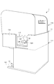
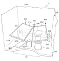
- FIG. 9 is a front perspective view showing a rehabilitation system 1A according to the second embodiment of the present invention.
- FIG. 10 is a plan view showing a forearm support member 128A of the rehabilitation system 1A according to the second embodiment of the present invention.
- the arrangement of the left-hand shooting camera 41A as the imaging device, the right-hand shooting camera 42A as the imaging device, the subject observation camera 43A, the left display 51A, the right display 52A, etc. is the first implementation. It differs from the configuration in the form. Since the configuration other than this is the same as the configuration in the first embodiment, the same configuration as each configuration in the first embodiment is denoted by the same reference numeral and description thereof is omitted.
- the left-hand photographing camera 41 ⁇ / b> A is disposed at the deepest position on the left end of the upper plate 125.
- the right hand photographing camera 42 ⁇ / b> A is disposed at the innermost position of the right end of the upper plate 125.
- Both the left-hand shooting camera 41A and the right-hand shooting camera 42A have a focal length of about 30 cm to 40 cm.
- the subject observation camera 43A is disposed in front of the display support 123A that supports the left display 51A and the right display 52A.
- the left display 51A and the right display 52A each have a rectangular plate shape as shown in FIG.
- the left display 51A, the left display unit 511A on the upper surface of the right display 52A, and the surface of the right display unit 521A constitute a display surface for displaying a part of the hand from the wrist, which is a part corresponding to the rehabilitation target part of the patient.
- mirrors 513A and 523A are provided as image reflecting portions, respectively.
- the mirror 513A located on the lower surface of the left display 51A reflects the patient's left hand once, and the left hand imaging camera 41A captures the image of the patient's left hand reflected by the mirror 513A.
- the mirror 523A located on the lower surface of the right display 52A reflects the patient's right hand once, and the right hand imaging camera 42A captures the image of the patient's right hand reflected by the mirror 523A.
- a through hole 118A is formed in the portion of the back wall 113A of the covering member 11A and in the vicinity of the upper plate 125.
- Natural light is configured to enter the target part accommodating space 127 ⁇ / b> A, which is a space between the left display 51 ⁇ / b> A and the right display 52 ⁇ / b> A, and the upper plate 125 through the through hole 118 ⁇ / b> A.
- the left hand of the patient is accommodated in the target part accommodating space 127A on the left side of the display support 123A.
- the patient's right hand is accommodated in the target part accommodation space 127A on the right side of the display support 123A.
- the target part accommodating space 127A accommodates the left hand and right hand of the patient. Even if the left hand and the right hand are moved while the forearm is placed on the forearm support member 128A described later, the left hand and the right hand are moved to the upper plate 125 and the left display 51A. In the vertical direction, the right display 52A is not touched. Accordingly, the left hand or right hand of the patient is arranged in a positional relationship close to the left display 51A and the right display 52A, and the left hand as a rehabilitation target site of the patient from the left display 51A and the right display 52A as a display unit, Alternatively, the distance to the right hand is configured to be much shorter than the distance from the left display 51A and the right display 52A to the patient's eyes.
- a forearm support member 128A is placed on the upper plate 125 below the left display 51A and the right display 52A.
- the forearm support member 128A includes a plate-like forearm placement portion 131A, a wrist placement convex portion 133A that is provided at the front portion of the forearm placement portion 131A and supports the wrist, and a wrist placement. And a plate-like tip plate-like portion 135A extending further forward from the convex portion 133A.
- a forearm extending from the patient's elbow to the wrist is placed on the forearm placement portion 131A.
- the wrist placement convex portion 133A protrudes above the upper surface of the forearm placement portion 131A (in the direction from the back side to the front side in FIG. 10), and supports the wrist.
- the upper surface of the tip plate-shaped portion 135A is positioned below the uppermost portion of the wrist placement convex portion 133A, and is configured so as not to touch the hand portion ahead of the wrist, particularly the fingertip. In this way, the upper surface of the tip plate-like portion 135A does not touch the fingertip or the like, so that the sense of the portion ahead of the patient's wrist can be sharpened.
- the upper surface of the tip plate-like portion 135A may be formed with a concave portion that is depressed downward, and the protruding height of the wrist placement convex portion 133A is higher than the wrist of the patient's wrist.
- This portion may be configured to be higher than the wrist placement convex portion 133A of the present embodiment to such an extent that this portion does not contact the lower surfaces of the left display 51A and the right display 52A.
- the forearm support member 128A is a forearm support member 128A that faces the hand portion from the wrist when the patient's forearm is placed on the forearm placement portion 131A of the forearm support member 128A and the patient's forearm is supported. It is configured to be rotatable around a predetermined portion of the tip plate-like portion 135A that is a portion of Specifically, it is a predetermined portion of the tip plate-like portion 135A, and is a lower portion of a portion in the vicinity of the wrist placement convex portion 133A (a portion on the opposite side to the upper surface side portion of the tip plate-like portion 135A shown in FIG. ) Has a rotating shaft 136A whose axis is oriented in the vertical direction. The entire forearm support member 128A including the distal plate portion 135A is rotatable about the rotation shaft 136A.
- the left display 51A and the right display 52A are supported by the display support unit 123A so as to be arranged with a predetermined positional relationship with the patient.
- the left display 51A, the left display 511A that is the display surface of the right display 52A, and the right display 521A are inclined so as to go upward as they move away from the patient toward the front of the patient.
- it is inclined at an angle in the range of 10 ° to 35 °, more preferably 15 ° to 25 ° with respect to the horizontal. This range of angles takes into consideration the line of sight when the patient seated so that the left display 51A and the right display 52A are positioned forward and the seating posture collapses and bends forward.
- the range of the tilt angle is set to the above range is that when the tilt angle is less than 10 °, the tilted effect can hardly be obtained. Moreover, when the angle of inclination exceeds 35 °, the angle is excessively inclined to make the patient feel uncomfortable.
- the left display 51A as the display unit, the left display unit 511A of the right display 52A, and the right display unit 521A are inclined upward along the left and right directions with the sagittal plane of the patient as the center. ing. Specifically, it is inclined at an angle in the range of 5 ° to 25 °, more preferably 10 ° to 20 ° with respect to the horizontal. This range of angles is intended for the case where the upper arm of the patient seated so that the left display 51A and the right display 52A are positioned in front of the patient is in a position along the scapular plane. .
- the position of the forearm relative to the upper arm of the patient whose upper arm is positioned along the scatter plane, the left display 51A, and the right display 52A This is because the positional relationship between the left display unit 511 ⁇ / b> A and the right display unit 521 ⁇ / b> A becomes unfavorable, and makes the patient feel uncomfortable.
- the left display 51A, the left display 511A of the right display 52A, and the right display 521A are positions in front of the patient and rotated in parallel in the horizontal direction around the position on the sagittal plane of the patient. Have a relationship. Specifically, on the sagittal plane and centered on a position in the range of 30 cm to 60 cm in front of the patient, more preferably in the range of 35 cm to 55 cm, the left display 51A is clockwise 5 ° to 20 °, more Preferably, it has a positional relationship that is rotated away from the sagittal plane at a rotation angle in the range of 7 ° to 17 °.
- the right display 52A has a positional relationship in which it is rotated away from the sagittal plane at a rotation angle in the range of 5 ° to 20 °, more preferably 7 ° to 17 ° in the counterclockwise direction. Yes.
- This range of angles is conscious of the case where the upper arm of the patient seated so that the left display 51A and the right display 52A are positioned in front of the patient is at a position along the scatter plane.
- the angle of rotation is less than 5 ° or when the angle of rotation exceeds 20 °, the position of the forearm relative to the patient's upper arm where the upper arm is positioned along the scapula plane, the left display 51A, and the right display 52A This is because the positional relationship between the left display unit 511 ⁇ / b> A and the right display unit 521 ⁇ / b> A becomes unfavorable, and the risk of making the patient feel uncomfortable increases.
- the rehabilitation system 1A is configured so that the distance from the left display 51A and the right display 52A as the display unit to the patient's rehabilitation target site is shorter than the distance from the left display 51A and the right display 52A to the patient's eyes. It has a target part receiving space 127A for storing a rehabilitation target part.
- the corresponding part displayed on the left display 51A or the right display 52A is arranged at a position close to the patient's rehabilitation target part, and is displayed on the left display 51A or the right display 52A.
- the patient can easily induce a self-motion illusion in the patient by viewing the corresponding part.
- the left-hand shooting camera 41A and the right-hand shooting camera 42A as the imaging device capture the corresponding portions reflected by the mirrors 513A and 523A as the image reflecting portions.
- the target part is accommodated so that the distance from the left display 51A and the right display 52A as the display unit to the patient's rehabilitation target part is shorter than the distance from the left display 51A and the right display 52A to the patient's eyes.
- the height of the space 127A can be kept small. As a result, the patient can easily induce the illusion of self-motion by viewing the corresponding part displayed on the left display 51A or the right display 52A disposed at a position close to the rehabilitation target part.
- the rehabilitation target part of the patient is a part of the hand from the wrist, and includes a forearm support member 128A that supports the forearm from the patient's elbow to the wrist.
- the forearm support member 128A is supported by the forearm support member 128A of the patient.
- the forearm support member 128A can be rotated about the portion of the forearm support member 128A facing the portion of the hand from the wrist.
- the forearm support member 128A when the patient's forearm is supported by the forearm support member 128A, the forearm support member 128A can be appropriately rotated around a position closer to the fingertip than the wrist. For this reason, the patient's upper arm can be easily arranged at a position along the scatter plane, so that the patient's forearm can be arranged at an appropriate position with respect to the left display 51A and the right display 52A. .
- the display surfaces of the left display 51A and the right display 52A are inclined so as to go upward as they move away from the patient toward the front of the patient. For this reason, even if the patient who is seated so that the left display 51A and the right display 52A are positioned in front of the patient and the posture of the seat collapses and bends forward, this tilt causes, for example, the left display 51A.
- the image of the right hand RH which is a corresponding part displayed on the screen, can be easily seen so as to naturally jump into the eyes of the patient.
- the display surfaces of the left display 51A and the right display 52A are directed upward along the left direction and the right direction with the sagittal plane of the patient as the center. So as to be inclined.
- the left display 51A, the left display 511A of the right display 52A, and the right display 521A are positions in front of the patient and rotated in parallel in the horizontal direction around the position on the sagittal plane of the patient. Have a relationship.
- the patient when the patient's upper arm is easily placed at a position along the scatter plane, the patient can display the left display 51A and the display surface of the right display 52A (the left display unit 511A and the right display unit 521A).
- the viewing direction is closer to the direction parallel to the normal line of the left display unit 511A and the right display unit 521A, and the image of the corresponding part displayed on the left display unit 511A and the right display unit 521A naturally appears to the patient's eyes. You can make it easier to see as if jumping into
- FIG. 11 is a schematic diagram showing a rehabilitation system 1B according to the third embodiment of the present invention.
- the above-described implementation is provided in that it includes a left display (not shown) as a display unit and a body drive unit 71B that drives in synchronization with the left hand LH as a corresponding portion displayed on the right display 52B. It differs from the configuration in the form. Since the configuration other than this is the same as the configuration in the above-described embodiment, the same configuration as each configuration in the above-described embodiment is denoted by the same reference numeral and description thereof is omitted.
- the body driving unit 71B may mechanically move the patient's body or may electrically move the patient's body. As shown in FIG. 11, as the body driving unit 71B that mechanically moves the patient's body, for example, a power assist device or the like that is attached to the rehabilitation target site and is driven by an actuator or the like to forcibly move the body is used. It is done. In addition, as a body drive unit that electrically moves the patient's body, for example, an electrical stimulation device that forcibly moves the body by contracting muscles by applying a low-frequency pulse current to the electrodes attached to the rehabilitation target site, etc. Is used. The body drive unit 71B is electrically connected to the control unit 30.
- the control unit 30 is driven by the body drive unit 71B in synchronization with a corresponding part (for example, the left hand LH) displayed on the right display 52B, so that the rehabilitation target part (for example, the right hand RH).
- the body drive unit 71B is controlled so as to move symmetrically with respect to the left hand LH. For this reason, when the patient is receiving visual stimulation by looking at the corresponding part (for example, the left hand LH) displayed on the right display 52B, the rehabilitation target part (for example, the right hand RH) is driven by the body drive unit 71B. Because it is moved, the patient can easily induce a self-motion illusion.
- FIG. 12 is a schematic diagram showing a rehabilitation system 1C according to the fourth embodiment of the present invention and a rehabilitation system 1D according to the fifth embodiment of the present invention.
- the fourth embodiment is different from the configuration in the third embodiment in that the body drive unit 71C is driven when a characteristic biological signal of a patient is detected. Since the configuration other than this is the same as the configuration in the third embodiment, the same configuration as each configuration in the above-described embodiment is denoted by the same reference numeral, and the description thereof is omitted.
- the rehabilitation system 1C includes a biological signal acquisition unit 711C and a characteristic biological signal detection unit 714C.
- the biological signal acquisition unit 711C acquires a biological signal from the patient.
- the biological signal acquisition unit 711C collects biological signals indicating brain activities such as brain wave signals and cerebral blood flow, or brain activities such as muscle action potentials and joint movements. For example, as shown in FIG. 12, the biological signal acquisition unit 711C is collected on the electrode 712C that is arranged on the forearm or scalp and captures a potential change caused by myoelectric activity or brain activity, or the electrode 712C.
- the myoelectric signal and the electroencephalogram signal are frequency-analyzed and output as signal intensity data for each frequency component.
- a near infrared spectroscopic blood flow meter or the like is used as a means for collecting cerebral blood flow.
- the characteristic biological signal detection unit 714C detects a characteristic biological signal indicating a state in which the self-motion illusion is induced. Specifically, the characteristic biological signal detection unit 714C analyzes the biological signal collected from the patient in real time and detects the characteristic biological signal. For example, the characteristic biological signal detection unit 714C analyzes the signal intensity data for each frequency component related to the myoelectric signal and the electroencephalogram signal acquired by the biological signal acquisition unit 711C. Then, the characteristic biological signal detection unit 714C detects the characteristic myoelectric activity or brain activity (biological signal) when the signal intensity exceeds the determination threshold or when the signal intensity falls below the determination threshold. To do.
- the control unit 30 controls the body driving unit 71C so that the body driving unit 71C is driven and a rehabilitation target part (for example, the right hand RH) moves when a characteristic biological signal is detected.
- a rehabilitation target part for example, the right hand RH
- the rehabilitation target part is the body drive unit 71C. It is moved by driving. Accordingly, since the patient can recognize that the rehabilitation target site (for example, the right hand RH) moves when the self-motion illusion is induced, the patient can recognize the rehabilitation target site (for example, the right hand RH). ) Can be encouraged to generate more biological signals.
- the left display (not shown) as a display unit and a right display 52D are displayed based on the characteristic biological signal. It differs from the configuration in the fourth embodiment in that the image of the part moves. Since the configuration other than this is the same as the configuration in the fourth embodiment, the same configuration as each configuration in the above-described embodiment is denoted by the same reference numeral, and the description thereof is omitted.
- the control unit 30 When the biological signal acquired by the biological signal acquisition unit 711D is analyzed by the electromyograph 713C by the characteristic biological signal detection unit 712D, and the characteristic biological signal is detected, the control unit 30 The body drive unit 71D is driven based on the detected characteristic biological signal, and the body drive unit 71D is controlled so that the rehabilitation target part (for example, the right hand RH) moves. At the same time, the control unit 30 displays a left display (not shown) and a right display so that an image of a corresponding part (for example, the left hand LH) synchronized with the driving movement of the body drive unit 71D is displayed on the right display 52D. Control is performed on 52D.
- the rehabilitation target part for example, the right hand RH
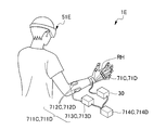
- FIG. 13 is a schematic view showing a rehabilitation system 1E according to the sixth embodiment of the present invention.
- a head-mounted display 51E is used in place of the left display 51 and the right display 52, which is different from the configuration in the above-described embodiment. Since the configuration other than this is the same as the configuration in the above-described embodiment, the same configuration as each configuration in the above-described embodiment is denoted by the same reference numeral and description thereof is omitted.
- the head mounted display 51E has a rehabilitation target part (for example, the right hand) compared to the case where the patient views the rehabilitation target part (for example, the right hand RH) of the patient without wearing the head mounted display 51E.
- the corresponding portion of RH) (for example, the left hand (not shown)) is displayed in a positional relationship overlapping the rehabilitation target portion (for example, the right hand RH) so that it can be seen from the patient.
- the left display 51 and the right display 52 it is possible to visually recognize a corresponding portion stably with appropriate brightness, color, and luminance for the patient, and the self-motion illusion can be stably and easily performed. It is possible to trigger on.
- the head mounted display 51E is excellent in portability compared with the left display 51 and the right display 52, it can perform rehabilitation without specifying a place.
- each configuration of the rehabilitation system is not limited to each configuration of the rehabilitation system 1 in the present embodiment.
- a sensory stimulus is given to the rehabilitation target part of the patient during the rehabilitation, and the left display 51 displayed on the rehabilitation target part is as if the sensory stimulus You may make it display the image
- a needle, a safety pin, a pin wheel, a roulette, etc. can be used as a stimulus imparting substance that gives a sensory stimulus by pain.
- a brush, cotton, a cotton swab, etc. can be used as a stimulus imparting substance that gives a sensory stimulus by touch.
- an electronic thermometer, a test tube or the like can be used as a temperature of about 40 ° C. to about 45 ° C. or about 10 ° C.
- a tuning fork etc. can be used as a stimulus imparting thing which gives the sensory stimulus by a vibration sense.
- a stimulus imparting substance that gives a sensory stimulus by a complex sense (two-point discrimination sense).
- Cotton, silk, wool, or the like can be used as a stimulus imparting agent that gives a sensory stimulus by a complex sense (discernment sense).
- Keys, coins, pens, blocks, and the like can be used as the stimulus imparting device that provides sensory stimulation by a complex sense (stereoscopic sense).
- a stimulus imparting substance that gives sensory stimulation by other complex sensations an eye mask, an ear plug, a sensory inspection sheet, or the like can be used.
- the therapist may open the window 116 (FIG. 1) and insert the stimulus imparting substance from the through hole 117 to contact the patient's rehabilitation target site.
- the stimulus imparting material may be automatically brought into contact with the rehabilitation target site of the patient in a state in which the image is synchronized with the image on the display unit due to the mechanical structure.
- the covering member 11 covers the patient, the left display 51 and the right display 52, the mounting table 12, and the like, and constitutes a dark place in which these are accommodated, but is not limited thereto.
- the covering member may cover at least the patient and the display unit and constitute a dark place that accommodates at least the patient and the display unit.
- the mounting table is not limited to the mounting table 12 in the present embodiment.
- a general general-purpose table may be used as the mounting table.
- a total of two displays, the left display 51 and the right display 52, are used as the rehabilitation display unit, but the present invention is not limited to this.
- the display unit one large display may be used, or three or more displays may be used.
- a head mounted display may be used in place of the two displays, the left display 51 and the right display 52 in total.
- the rehabilitation system may not have a covering member or a mounting table.
- the left display 51 shields the left hand from the patient's eyes so that the patient's eyes cannot see the left hand as the patient's rehabilitation target site, but the present invention is not limited to this.
- the display part should just be able to shield a patient's rehabilitation object site
- control unit 30 switches the left-right inverted video of the right hand displayed on the left display 51 as the display unit alternately at a random timing between a moving state and a stationary state.
- the left display 51 is controlled, the present invention is not limited to this.
- the image of the corresponding part that is reversed left and right displayed on the display unit may be displayed in a state of being moved continuously without being stopped.
- the start of imaging is triggered by whether or not the motion determination data of the video captured by the right-handed camera 42 exceeds the start determination threshold set in step S13 as a trigger for starting recording.
- the right hand camera 42 is controlled so that the right hand camera 42 is controlled, and whether or not the stop determination threshold is exceeded is used as a trigger for ending the recording.
- the control unit may control the imaging device so that imaging start and imaging end by the imaging device are performed based on the operation of the corresponding part.
- the control unit may use other triggers, for example, myoelectricity or brain waves, instead of performing the imaging start and imaging end by the imaging device based on the operation of the corresponding part.
- part was the left hand, it is not limited to this.
- the rehabilitation target site of the patient may be the right hand, or the left foot or the right foot.
- the display procedure and the display target for displaying the images captured by the left-hand shooting camera 41A and the right-hand shooting camera 42A on the left display 51 and the right display 52 are the display procedure and display target according to the present embodiment. It is not limited to.
- the rehabilitation target part of the patient is the left hand
- images taken by the left hand photographing camera 41A and the right hand photographing camera 42A are displayed on the left display 51 and the right display 52, respectively.
- the patient keeps watching it for a while.
- the right hand of the patient displayed on the right display 52A moves as intended by the patient, but the left hand of the patient displayed on the left display 51A does not move as intended by the patient.
- a position on the left display 51 where the left hand of the patient has been displayed so far after a predetermined time such as when the movement of the right hand of the patient is reduced so that the patient cannot notice
- the right hand of the patient photographed by the right hand photographing camera 42 ⁇ / b> A is reversed left and right and displayed on the left display 51. Such shooting and display may be performed.
- the left display unit 511A and the right display unit 521A as display surfaces of the left display 51A and the right display 52A are inclined so as to go upward as they move away from the patient in front of the patient. Inclined to move upward along the left and right directions around the sagittal plane of the patient, and parallel to the horizontal position around the position on the patient's sagittal plane at the front of the patient.
- the present invention is not limited to this configuration.
- the display surfaces (the left display unit 511A and the right display unit 521A) of the left display 51A and the right display 52A do not tilt at all and may not rotate at all.
- the left display unit 511A and the right display unit 521A of the left display 51A and the right display 52A are inclined so as to go upward as they move away from the patient, but centered on the sagittal plane of the patient. It is not inclined so as to go upward along each of the left direction and the right direction, and is further rotated in parallel in the horizontal direction around the position on the patient's sagittal plane in front of the patient. You may have the positional relationship which is not made.
- the left display unit 511A and the right display unit 521A of the left display 51A and the right display 52A are inclined so as to go upward as they move away from the patient, and the left display unit 521A is centered on the sagittal plane of the patient. Is tilted upward along each of the direction and right direction, but is a position in front of the patient that is not rotated parallel to the horizontal direction around the position on the patient's sagittal plane You may have a relationship.
- the values of the tilt angle and the rotation angle of the left display 51A and the right display 52A are not limited to the values of the tilt angle and the rotation angle of the left display 51A and the right display 52A in the second embodiment. It may be adjustable or it may be fixed.
- mirrors 513A and 523A as image reflecting portions on the lower surface of the left display 51A and the lower surface of the right display 52A each reflect the patient's left hand located on the lower surface of the left display 51A once, and the right display 52A.
- the patient's right hand located on the lower surface is reflected once, the present invention is not limited to this. For example, it may be reflected more than once using another mirror.
- the target patient of the rehabilitation system, the rehabilitation program, and the rehabilitation method according to the present invention is not limited to the hemiplegic patient as described above.
- phantom limb pain that causes pain in the amputated extremity, or after local area (extremity etc.) is forced to rest due to injury such as fracture, etc.
- Patients who have pain that remains after the wound has healed, such as pain that remains, may be targeted.
Landscapes
- Health & Medical Sciences (AREA)
- Epidemiology (AREA)
- Pain & Pain Management (AREA)
- Physical Education & Sports Medicine (AREA)
- Rehabilitation Therapy (AREA)
- Life Sciences & Earth Sciences (AREA)
- Animal Behavior & Ethology (AREA)
- General Health & Medical Sciences (AREA)
- Public Health (AREA)
- Veterinary Medicine (AREA)
- Rehabilitation Tools (AREA)
Abstract
自発的に身体を動かそうという意思を発現できない患者に対しても自己の身体が運動をしているような自己運動錯覚を誘起させて、高いリハビリテーション効果を得ることができるリハビリテーションシステム、リハビリテーション用プログラム、及び、リハビリテーション方法を提供すること。 リハビリテーションシステムの制御部は、患者が直接患者のリハビリ対象部位を見た場合の、患者のリハビリ対象部位の見た目の大きさよりも、患者が表示部51に表示された相当部位RHの映像を見た場合の、相当部位RHの映像の見た目の大きさの方が、患者から見て大きく見えるように、表示部51に対して制御を行う。
Description
本発明は、患者自らの意志による随意運動が困難又は不能になったリハビリ対象部位を有する患者のリハビリテーションに用いる、リハビリテーションシステム、リハビリテーション用プログラム、及び、リハビリテーション方法に関する。
従来より、患者にリハビリテーションを行うためのリハビリ装置が知られている。例えば、特許文献1に記載のリハビリ装置は、患者に麻痺した身体部分の正常な動きを見せる視覚刺激装置と、身体を駆動する身体駆動装置と、患者の生体信号を検知する手段と、検知した生体信号から身体を駆動させるためのデータを生成する手段と、生成されたデータを身体駆動装置に送信する手段とを有している。プログラムに基づく制御によってリハビリ装置は、生体信号の検知又は外部信号をトリガとして、視覚刺激装置と協調して身体駆動装置が、患者に見せる身体部分の動きと同じ動きを患者に対して強制的に行い、一定時間当該動きを継続するように動作する。
しかし、脳卒中後の片麻痺患者等においては、損傷半球の運動野に対して非損傷半球から異常な抑制性の入力がある、いわゆる異常半球間抑制が知られており、当該異常半球間抑制により、自分で運動しようとする意思の生成が困難になっていると考えられている。このため、特許文献1に記載されているように、身体を動かすことはおろか、自発的に身体を動かそうという意思すら発現できないという問題がある。
また、特許文献1に記載の装置では、患者の生体信号をトリガとして利用できないときには、所定間隔で発せられる音等の外部信号をトリガとして利用する。しかし、外部信号を利用する場合には、患者の意思とは全く無関係に視覚刺激装置や身体駆動装置を動作させるため、現実にはリハビリテーション効果を期待できない。
本発明は、自発的に身体を動かそうという意思を発現できない患者に対しても自己の身体が運動をしているような自己運動錯覚を誘起させて、高いリハビリテーション効果を得ることができるリハビリテーションシステム、リハビリテーション用プログラム、及び、リハビリテーション方法を提供することを目的とする。
本発明は、患者自らの意志による随意運動が困難又は不能になったリハビリ対象部位を有する患者のリハビリテーションに用いるリハビリテーションシステムであって、患者の目に対して患者のリハビリ対象部位を遮蔽可能な表示部と、患者のリハビリ対象部位が運動しているとの自己運動錯覚を患者に誘起させるための視覚刺激を患者に与えるために、患者のリハビリ対象部位に相当する相当部位が動いている映像を、患者から見て患者のリハビリ対象部位に重なる位置関係で前記表示部に表示するように、前記表示部に対して制御を行う制御部と、を備え、前記制御部は、患者が直接患者のリハビリ対象部位を見た場合の、患者のリハビリ対象部位の見た目の大きさよりも、患者が前記表示部に表示された前記相当部位の映像を見た場合の、前記相当部位の映像の見た目の大きさの方が、患者から見て大きく見えるように、前記表示部に対して制御を行うリハビリテーションシステムに関する。
また、前記制御部は、前記表示部に表示される前記相当部位の映像を、動いている状態と静止している状態とで交互に切替えを行うように、前記表示部に対して制御を行うことが好ましい。
また、患者の部位を撮像可能な撮像装置を備え、前記制御部は、患者のリハビリ対象部位が患者の身体において左右で対をなしている一方の部位である場合に、他方の部位を撮像するように前記撮像装置に対して制御を行い、前記撮像した他方の部位の映像を左右反転させた映像を、前記相当部位の映像として前記表示部に表示するように、前記表示部に対して制御を行うことが好ましい。
また、前記制御部は、前記撮像装置による撮像開始及び撮像終了を前記相当部位の動作に基づいて行うように、前記撮像装置に対して制御を行うことが好ましい。
また、前記制御部は、前記表示部において、前記撮像装置により撮像されているリアル画像と、前記撮像装置により撮像され録画された録画画像とを切替えて表示するように、前記表示部に対して制御を行い、少なくとも前記リアル画像から前記録画画像へ切替えるときに、オーバーレイ機能により、前記リアル画像における前記相当部位の映像から、前記録画画像における前記相当部位の映像へ、前記相当部位が連続的になめらかに移行するように表示するように、前記表示部に対して制御を行うことが好ましい。
また、前記表示部から患者のリハビリ対象部位までの距離を、前記表示部から患者の目までの距離よりも短くするように、前記患者のリハビリ対象部位を収容する対象部位収容空間を有することが好ましい。また、前記撮像装置は、像反射部に反射された前記相当部位を撮像することが好ましい。
また、少なくとも患者と前記表示部とを覆い、少なくとも患者及び前記表示部を収容する暗所を構成する覆い部材を備えることが好ましい。
また、患者のリハビリ対象部位は、手首から先の手の部分であり、患者の肘から手首までの前腕を支持する前腕支持部材を備え、前記前腕支持部材は、前記前腕支持部材により患者の前腕が支持されているときに、手首から先の手の部分に対向する前記前腕支持部材の部分を中心として回転可能であることが好ましい。
また、前記表示部の表示面は、患者から患者の前方へ遠ざかるにつれて上方へ向かうように傾斜していることが好ましい。また、前記表示部の表示面は、患者の矢状面を中心として左方向、右方向のそれぞれに沿って上方へ向かうように傾斜していることが好ましい。また、前記表示部の表示面は、患者の前方の位置であって患者の矢状面上の位置を中心として水平方向に平行に回転させられた位置関係を有することが好ましい。
また、患者のリハビリ対象部位を強制的に動かす身体駆動部を備え、前記制御部は、前記表示部に表示された前記相当部位に前記身体駆動部が同期して駆動するように前記身体駆動部に対して制御を行うことが好ましい。
また、患者のリハビリ対象部位を強制的に動かす身体駆動部と、前記患者から生体信号取得する生体信号取得部と、前記自己運動錯覚が誘起された状態を示す特徴的な生体信号を検出する特徴的生体信号検出部と、を備え、前記制御部は、前記特徴的な生体信号を検出したときに、前記身体駆動部が駆動するように前記身体駆動部に対して制御を行うことが好ましい。
また、前記制御部は、前記特徴的な生体信号を検出したときに、前記身体駆動部が駆動するように前記身体駆動部に対して制御を行うと共に、前記表示部に表示される前記相当部位の映像が前記身体駆動部と同期して動くように、前記表示部に対して制御を行うことが好ましい。
また、本発明は、患者自らの意志による随意運動が困難又は不能になったリハビリ対象部位を有する患者のリハビリテーションに用いるリハビリテーション用プログラムであって、患者のリハビリ対象部位が運動しているとの自己運動錯覚を患者に誘起させるための視覚刺激を患者に与えるために、患者のリハビリ対象部位に相当する相当部位が動いている映像を、患者の目に対して患者のリハビリ対象部位を遮蔽可能な表示部に、患者から見て患者のリハビリ対象部位に重なる位置関係で表示させ、患者が直接患者のリハビリ対象部位を見た場合の、患者のリハビリ対象部位の見た目の大きさよりも、患者が前記表示部に表示された前記相当部位の映像を見た場合の、前記相当部位の映像の見た目の大きさの方が、患者から見て大きく見えるように、前記相当部位の映像を前記表示部に表示させるように、コンピュータを機能させるリハビリテーション用プログラムに関する。
また、本発明は、患者自らの意志による随意運動が困難又は不能になったリハビリ対象部位を有する患者のリハビリテーションに用いるリハビリテーション方法であって、患者のリハビリ対象部位が運動しているとの自己運動錯覚を患者に誘起させるための視覚刺激を患者に与えるために、患者のリハビリ対象部位に相当する相当部位が動いている映像を、患者の目に対して患者のリハビリ対象部位を遮蔽可能な表示部に、患者から見て患者のリハビリ対象部位に重なる位置関係で表示させる、相当部位の映像表示ステップを備え、前記映像表示ステップは、患者が直接患者のリハビリ対象部位を見た場合の、患者のリハビリ対象部位の見た目の大きさよりも、患者が前記表示部に表示された前記相当部位の映像を見た場合の、前記相当部位の映像の見た目の大きさの方が、患者から見て大きく見えるように、前記相当部位の映像を前記表示部に表示させる、相当部位の映像拡大表示ステップを有する、リハビリテーション方法に関する。
本発明によれば、自発的に身体を動かそうという意思を発現できない患者に対しても自己の身体が運動をしているような自己運動錯覚を誘起させて、高いリハビリテーション効果を得ることができるリハビリテーションシステム、リハビリテーション用プログラム、及び、リハビリテーション方法を提供することができる。
以下、本発明の第1実施形態について図1~図8に基づき説明する。リハビリテーションシステム1は、患者自らの意志による随意運動が困難又は不能になったリハビリ対象部位を有する患者のリハビリテーションに用いるリハビリテーションシステムであり、図1~図3に示すように、覆い部材11と、載置台12と、制御部30と、撮像装置としての左手撮影用カメラ41と、撮像装置としての右手撮影用カメラ42と、被験者観察用カメラ43と、表示部としての左側ディスプレイ51と、表示部としての右側ディスプレイ52と、オペレータ用ディスプレイ53と、被験者観察用ディスプレイ54と、入力部61と、を備えている。
載置台12は、脚部121と、上板125とを有するテーブルにより構成されている。脚部121は、電動のアクチュエータ(図示せず)を有しており、電動のアクチュエータが駆動することにより、上下方向に伸縮し、これにより、上板125の高さを調整可能である。上板125は脚部121の上端部に固定されている。上板125は略長方形状を有しており、一対の長辺のうちの一方の長辺の中央部は、上板125の中央向かって半円形状に窪んだ切り欠き部126を有している。リハビリテーションシステム1を使用する患者から見て、切り欠き部126を有する上板125の一方の長辺が手前側に配置され、切り欠き部126を有する上板125の他方の長辺が奥側に配置され、椅子や車椅子等に腰かけた状態の患者が、半円形状に窪んだ切り欠き部126に位置し、且つ、載置台12の手前側から奥側を向いた位置(以下「使用位置」と言う)で、載置台12は患者によって使用される。
覆い部材11は、載置台12を取り囲む下部111と、載置台12の上方を覆う上部115とを有している。下部111は、板状の部材により構成されており、載置台12の奥側及び左右側部を取り囲むように構成されている。上部115は、載置台12の上方の空間の全体を覆うように構成されている。従って、覆い部材11は、リハビリテーションシステム1を使用する患者から見て、リハビリテーションシステム1の手前側において開口している。この構成により、覆い部材11は、患者と後述の表示部としての左側ディスプレイ51及び右側ディスプレイ52を覆い、患者及び表示部としての左側ディスプレイ51及び右側ディスプレイ52を収容する暗所を構成する。
覆い部材11の左右の側部は、窓116を有している。窓116は、患者から見て奥方向又は手前方向にスライド可能であり、手前方向にスライドすることにより、窓116が開き、奥方向にスライドすることにより、窓116が閉じるように構成されている。窓116を開いた状態として、貫通孔117を通してオペレータやセラピストが、覆い部材11により覆われている患者のリハビリテーションを行っている様子を、目視で確認することができるように構成されている。また、覆い部材11の上部115を構成する奥側の壁部の上端部には、通気孔118が形成されている。
左側ディスプレイ51、右側ディスプレイ52、オペレータ用ディスプレイ53、被験者観察用ディスプレイ54、左手撮影用カメラ41、右手撮影用カメラ42、被験者観察用カメラ43、及び、入力部61は、制御部30に電気的に接続されている。
左手撮影用カメラ41、右手撮影用カメラ42、及び、被験者観察用カメラ43は、CCDカメラ等により構成されている。左手撮影用カメラ41は、使用位置にいる患者の左手を撮影可能に、使用位置にいる患者の左手の上方に位置する覆い部材11の内側の上部に固定されている。右手撮影用カメラ42は、使用位置にいる患者の右手を撮影可能に、使用位置にいる患者の右手の上方に位置する覆い部材11の内側の上部に固定されている。被験者観察用カメラ43は、使用位置にいる患者の様子を撮影可能に、使用位置にいる患者の上方に位置する覆い部材11の内側の上部に固定されている。
入力部61は、キーボード、マウス、タッチパネル等(図示せず)により構成されている。入力部61は、覆い部材11の外部に設置されている。入力部61を構成するタッチパネルは、オペレータ用ディスプレイ53上に設けられている。入力部61からの入力に基づき、制御部30における各種の設定を行うことができるように構成されている。
オペレータ用ディスプレイ53及び被験者観察用ディスプレイ54は、入力部61を構成するキーボードやマウス、後述の制御部30を構成するコンピュータと同様に、覆い部材11の外部に設置されている。オペレータ用ディスプレイ53は、入力部61から制御部30への入力に基づく設定値等を表示する。被験者観察用ディスプレイ54は、被験者観察用カメラ43により撮影された被験者としての患者の様子を表示する。
左側ディスプレイ51は、左側ディスプレイ部511と左側モニターアーム512とを有している。同様に、右側ディスプレイ52は、右側ディスプレイ部521と右側モニターアーム522とを有している。左側ディスプレイ部511は、載置台12の上板125に載置された左側モニターアーム512によって、支持されている。右側ディスプレイ部521は、載置台12の上板125に載置された右側モニターアーム522によって、支持されている。従って、左側ディスプレイ部511と載置台12の上板125との間には、患者の左手を挿入する空間が形成されている。同様に、右側ディスプレイ部521と載置台12の上板125との間には、患者の右手を挿入する空間が形成されている。
左側ディスプレイ51は、患者のリハビリ対象部位が左手である場合に使用され、右側ディスプレイ52は、患者のリハビリ対象部位が右手である場合に使用される。例えば、患者のリハビリ対象部位が左手である場合には、図8に示すように、左手を左側ディスプレイ部511と載置台12の上板125との間の空間に挿入することにより、左側ディスプレイ51は、患者の目に対して患者のリハビリ対象部位である左手を遮蔽する。その際、左側ディスプレイ51には、例えば、撮影された患者の右手が左右反転させられ、且つ、設定された倍率で拡大されて表示される。このとき、左腕LAは、患者の目によって直接目視されている。同様に、患者のリハビリ対象部位が右手である場合には、右手を右側ディスプレイ部521と載置台12の上板125との間の空間に挿入することにより、右側ディスプレイ52は、患者の目に対して患者のリハビリ対象部位である右手を遮蔽する。その際、右側ディスプレイ52には、例えば、撮影された患者の左手が左右反転させられ、且つ、設定された倍率で拡大されて表示される。
制御部30は、CPU等の演算処理装置と記憶部とを有するコンピュータにより構成されている。制御部30は、覆い部材11の外部に設置されており、ROM(Read OnlyMemory)、RAM(Random Access Memory)、及び、フラッシュメモリ等を有しており、リハビリテーション用プログラムが、各種のデータやプログラムとともに記憶されている。リハビリテーション用プログラムが実行されることにより、例えば、前述のように、左側ディスプレイ51に、撮影された患者の右手が左右反転させられて表示されたり、右側ディスプレイ52に、撮影された患者の左手が左右反転させられて表示されたりするように、制御部30は、左側ディスプレイ51や右側ディスプレイ52等に対して制御を行う。
次に、リハビリテーション用プログラム及び、リハビリテーション方法について、リハビリテーション用プログラムが実行されたときの制御部30による制御に基づき説明する。左側ディスプレイ51に対する制御部30の制御と、右側ディスプレイ52に対する制御部30の制御とは、表示等が左右対称であること以外は同様であるため、以下、左側ディスプレイ51に対する制御部30の制御について説明し、右側ディスプレイ52に対する制御部30の制御については、説明を省略する。同様に、患者については、患者のリハビリ対象部位が左手である場合について説明し、患者のリハビリ対象部位が右手である場合については、説明を省略する。
リハビリテーション用プログラムが実行されることにより、制御部30は、患者のリハビリ対象部位としての左手が運動しているとの自己運動錯覚を患者に誘起させるための視覚刺激を患者に与えるために、患者のリハビリ対象部位に相当する相当部位としての右手が動いている映像を、患者から見て患者のリハビリ対象部位である左手に重なる位置関係で、表示部としての左側ディスプレイ51に表示するように、左側ディスプレイ51に対して制御を行う。この際、制御部30は、患者が直接患者のリハビリ対象部位である左手を見た場合の、患者の左手の見た目の大きさよりも、患者が表示部としての左側ディスプレイ51に表示された相当部位としての右手の映像を見た場合の、右手の映像の見た目の大きさの方が、患者から見て大きく見えるように、左側ディスプレイ51に対して制御を行う。これにより、リハビリテーション方法が実施される。ここで、「左側ディスプレイ51に対して~を表示する制御を行う」とは、左側ディスプレイ51において~が表示されるように、左側ディスプレイ51に対して制御を行う場合のみならず、広く、左側ディスプレイ51において~が表示されるように、~のデータが、制御部から左側ディスプレイ51へ出力されて、それが左側ディスプレイ51においてそのまま表示され、結果として、左側ディスプレイ51において、~が表示される場合までも含むことを意味する。
具体的には、リハビリテーションシステム1は、オペレータにより操作されることにより、患者のリハビリテーションを行う。先ず、リハビリテーションシステム1が起動させられると、ステップS1において、制御部30は、オペレータにデバイスの選択を促す表示をオペレータ用ディスプレイ53に表示する制御を、オペレータ用ディスプレイ53に対して行う。具体的には、例えば、患者のリハビリ対象部位が左手である場合には、左手のリハビリテーション用のデバイスを選択する旨を入力し、患者のリハビリ対象部位が右手である場合には、右手のリハビリテーション用のデバイスを選択する旨を入力する。その他、例えば、患者のリハビリテーションと同時に被験者を観察する場合には、被験者(患者)観察用のデバイスを選択する旨を入力し、アナログ出力を行う場合には、アナログ出力用のデバイスを選択する旨を入力する。そして、制御部30による処理は、ステップS2へ進む。
ステップS2において制御部30は、ステップ1において設定したデバイスの確認を促す表示をオペレータ用ディスプレイ53に表示する制御を、オペレータ用ディスプレイ53に対して行う。そして、オペレータによる入力部61からの入力が、デバイスの設定がOKである旨の場合には(YES)、制御部30による処理は、ステップS3へ進む。オペレータによる入力部61からの入力が、デバイスの設定がOKではなく、設定をキャンセルする場合には(NO)、制御部30による処理は、システムを終了するフロー(図7)へ進む。
ステップS3において制御部30は、カメラ及びディスプレイの選択をオペレータに促す表示をオペレータ用ディスプレイ53に表示する制御を、オペレータ用ディスプレイ53に対して行う。具体的には、制御部30は、左手撮影用カメラ41、右手撮影用カメラ42のうちから、使用するカメラの選択を促す表示をオペレータ用ディスプレイ53に表示する制御を、オペレータ用ディスプレイ53に対して行う。また、制御部30は、左側ディスプレイ51、右側ディスプレイ52のうちから、使用するディスプレイの選択を促す表示をオペレータ用ディスプレイ53に表示する制御を、オペレータ用ディスプレイ53に対して行う。そして、制御部30による処理は、ステップS4へ進む。
ステップS4において制御部30は、右手撮影用カメラ42によって撮影され、オペレータ用ディスプレイ53に表示された患者の右手について、オペレータ用ディスプレイ53上において、当該右手の全体を含むような領域の選択を促す表示をオペレータ用ディスプレイ53に表示する制御を、オペレータ用ディスプレイ53に対して行う。具体的には、オペレータによる、入力部61を構成するマウスの操作により、矩形515(図8参照)が患者の右手全体を含むように当該矩形をオペレータ用ディスプレイ53に表示させるように、制御部30は、オペレータ用ディスプレイ53に対して制御を行う。そして、制御部30による処理は、ステップS5へ進む。
ステップS5において制御部30は、カメラ、映像の調整を促す表示をオペレータ用ディスプレイ53に表示する制御を、オペレータ用ディスプレイ53に対して行う。具体的には、カメラによる撮影された画像を左右反転させるか否かの選択や、カメラによる撮影された画像をどの程度拡大させて左側ディスプレイ51に表示させるかについての拡大数値(%)の入力や、カメラの露出、焦点、ホワイトバランス、輝度、コントラスト、彩度、明度等の設定を自動設定とするか手動設定とするかの選択や、これらの設定を手動選択とした場合の各値の入力や、色調(RGB)の値の入力等を促す表示をオペレータ用ディスプレイ53に表示する制御を、オペレータ用ディスプレイ53に対して行う。これに対してオペレータは、これらについて、入力部61を構成するキーボードやマウスやタッチパネルを操作することにより、設定を行う。そして、制御部30による処理は、ステップS6へ進む。
ステップS6において制御部30は、患者のリハビリテーションに際して、録画再生処理を行うか、ライブラリ再生を行うかの選択を促す表示をオペレータ用ディスプレイ53に表示する制御を、オペレータ用ディスプレイ53に対して行う。これに対してオペレータは、録画再生処理を行うか、ライブラリ再生処理を行うかの選択を、オペレータ用ディスプレイ53上において、入力部61を構成するマウスやタッチパネルを操作することにより行う。オペレータによる入力部61からの入力が、録画再生処理を行う旨の選択である場合には(YES)、制御部30による処理は、録画再生処理フロー(図5)へ進む。オペレータによる入力部61からの入力が、ライブラリ再生処理を行う旨の選択である場合には(NO)、制御部30による処理は、ライブラリ再生処理フロー(図6)へ進む。
録画再生処理フロー(図5)においては、制御部30は、右手撮影用カメラ42により撮影された画像を、左側ディスプレイ51に表示させるための一連の制御を行う。具体的には、先ず、ステップS11において制御部30は、録画条件の設定を促す表示をオペレータ用ディスプレイ53に表示する制御を、オペレータ用ディスプレイ53に対して行う。具体的には、録画中にブザーを鳴動する周期が設定される録画タクトの値や、録画回数等の設定や、ライブラリファイルを作成するか否かの選択を、オペレータ用ディスプレイ53上において、入力部61を構成するマウスやタッチパネルを操作することにより行う。そして、制御部30による処理は、ステップS12へ進む。
ステップS12において制御部30は、録画の開始、終了のトリガとして、患者のリハビリ対象部位である左手に相当する相当部位である右手の動作を用いるか否かの選択を促す表示をオペレータ用ディスプレイ53に表示する制御を、オペレータ用ディスプレイ53に対して行う。録画の開始、終了のトリガとして、患者のリハビリ対象部位である左手に相当する相当部位である右手の動作を用いることにより、映像(動画)の録画開始、録画停止を画像認識から自動化して行うことになる。これに対してオペレータは、右手の動作をトリガとして用いるか、又は、用いないかを選択する。オペレータによる入力部61からの入力が、右手の動作をトリガとして用いる旨の選択である場合には(YES)、制御部30による処理は、ステップS13へ進む。オペレータによる入力部61からの入力が、右手の動作をトリガとして用いない旨の選択である場合には(NO)、制御部30による処理は、ステップS15へ進む。
ステップS13において制御部30は、録画の開始、終了のトリガとして、患者のリハビリ対象部位である左手に相当する相当部位である右手の動作を用いるための動作検出値の設定を促す表示をオペレータ用ディスプレイ53に表示する制御を、オペレータ用ディスプレイ53に対して行う。具体的には、右手撮影用カメラ42による撮影の際の動作開始検出における、1フレーム前の画像と現在の画像との変化率の閾値の設定である開始判別閾値(%)や、この閾値を連続して何回超えたら開始を行うかについての値である開始判別回数や、右手撮影用カメラ42による撮影の際の動作停止検出における、1フレーム前の画像と現在の画像との変化率の閾値の設定である停止判別閾値(%)や、この閾値を連続して何回超えたら停止を行うかについての値である停止判別回数等の設定を、オペレータ用ディスプレイ53上において、入力部61を構成するマウスやタッチパネルを操作することにより行う。そして、制御部30による処理は、ステップS14へ進む。
ステップS14において制御部30は、オーバーレイの設定を促す表示をオペレータ用ディスプレイ53に表示する制御を、オペレータ用ディスプレイ53に対して行う。具体的には、オーバーレイ機能を使用するか否かの選択や、オーバーレイ機能を使用する場合の、オーバーレイ処理の透過度処理ループの変化値を設定する透過度分解能の値や、オーバーレイ処理の透過度処理ループのタイマ設定値を設定する時間分解能の値等の設定を、オペレータ用ディスプレイ53上において、入力部61を構成するマウスやタッチパネルを操作することにより行う。そして、制御部30による処理は、ステップS15へ進む。
ステップS15において制御部30は、患者のID及び録画する画像の動作名(ファイル名)の入力を促す表示をオペレータ用ディスプレイ53に表示する制御を、オペレータ用ディスプレイ53に対して行う。具体的には、患者のID及び録画する画像の動作名(ファイル名)が、入力部61を構成するマウスやキーボードやタッチパネルが操作されることにより、入力される。そして、制御部30による処理は、ステップS16へ進む。
ステップS16において制御部30は、録画を行う回数の入力を促す表示をオペレータ用ディスプレイ53に表示する制御を、オペレータ用ディスプレイ53に対して行う。具体的には、録画開始から録画停止までを1回として、何回録画を行うかについての回数が、入力部61を構成するマウスやキーボードやタッチパネルが操作されることにより、入力される。そして、制御部30による処理は、ステップS17へ進む。
ステップS17において制御部30は、ステップS11~S16において設定された録画についての各種の設定に基づき、録画を行うように、右手撮影用カメラ42に対して制御を行う。これにより、患者のリハビリ対象部位が患者の身体において左右で対をなしている一方の部位である左手であることに対して、他方の部位である右手の撮像が行われる。この際、制御部30は、撮像装置としての右手撮影用カメラ42による撮像開始を、相当部位としての右手の動作開始に基づいて行い、右手撮影用カメラ42による撮像開始、撮像終了を右手の動作停止により行うように、右手撮影用カメラ42に対して制御を行う。具体的には、右手撮影用カメラ42により撮像された映像の動きのデータについて、ステップS13において設定された開始判別閾値を超えているか否かを、録画の開始のトリガとして、撮像開始を行うように、右手撮影用カメラ42に対して制御を行い、また、停止判別閾値を超えているか否かを、録画の終了のトリガとして、撮像終了を行うように、右手撮影用カメラ42に対して制御を行う。そして、制御部30による処理は、ステップS18へ進む。
ステップS18において制御部30は、ステップS17において得られた映像を二値化して、リアル映像を取得する制御を行う。そして、制御部30による処理は、ステップS19へ進む。
ステップS19において制御部30は、ステップ18において得られたリアル映像を左側ディスプレイ51に表示する制御を、左側ディスプレイ51に対して行う。即ち、リハビリテーション方法における、相当部位である右手RHの映像表示ステップが行われる。具体的には、制御部30は、図8に示すように、撮像した他方の部位としての右手RHの映像を左右反転させた映像を、相当部位の映像として表示部としての左側ディスプレイ51の左側ディスプレイ部511に表示する。左側ディスプレイ51に表示された、左右反転された右手RHの映像は、患者から見て、左側ディスプレイ51の下方に差し込まれた左手に重なる位置関係で左側ディスプレイ51に表示される。即ち、患者の左腕LAの先端においてあたかも患者の左手が見えているかのように、左側ディスプレイ51の左側ディスプレイ部511において表示が行われる。更に、左側ディスプレイ51に表示された、左右反転された右手RHの映像は、患者から見て患者の左手に対して1.2倍程度拡大されて見えるように、拡大されて表示されている。即ち、リハビリテーション方法における、相当部位の映像拡大表示ステップが行われる。
拡大する倍率は1.2倍に固定ではなく、1倍~2倍の間で可変に構成されており、例えば、1.1倍~1.4倍程度が好ましい。1.1倍よりも小さいと映像が小さすぎて、自己運動錯覚を患者に誘起させるための視覚刺激を、効果的に患者に与えることができないからである。また、1.4倍よりも大きいと映像が大きすぎて、自己運動錯覚を患者に誘起させるための視覚刺激を、効果的に患者に与えることができないからである。
また、制御部30は、表示部としての左側ディスプレイ51に表示されている左右反転された右手の映像について、動いている状態と静止している状態とで、ランダムなタイミングで交互に切替えを行うように、左側ディスプレイ51に対して制御を行う。具体的には、例えば、静止している状態の、左右反転された右手の映像であるリアル画像から、ステップS17において録画された、動いている状態の、左右反転された右手RHの映像である録画画像へ、ランダムなタイミングで切替える。この際、オーバーレイ機能により、リアル画像における相当部位である右手RHの映像から、録画画像における相当部位である右手RHの映像へ、右手RHが連続的になめらかに移行するように左側ディスプレイ51に表示するように、制御部30は左側ディスプレイ51に対して制御を行う。ここで、「連続的になめらかに移行する」とは、例えば、リアル画像における相当部位である右手RHの映像において徐々に透明度が高まり、ある程度透明になったところから再び右手RHの肌の色に近づいて行き、右手RHの肌の色に戻ったときには、録画画像における右手RHの映像が表示されている、といったオーバーレイが、一例として挙げられる。このような左側ディスプレイ51に表示される左右反転された右手RHの映像を見た患者は、自己の身体が運動をしているようないわゆる自己運動錯覚が誘起させられ、リハビリテーションが行なわれる。そして、制御部30による処理は、ステップS20へ進む。
ステップS20において制御部30は、ステップS16において設定された回数分の録画が行われたか否かの判断を行う。ステップS16において設定された回数分の録画が行われた場合には(YES)、制御部30による処理は、ステップS21へ進む。ステップS16において設定された回数分の録画が行われていない場合には(NO)、制御部30による処理は、ステップS17へ戻る。
ステップS21において制御部30は、入力部61から、映像の再生処理を停止すべき旨の入力があったか否かの判断を行う。入力部61から、映像の再生処理を停止すべき旨の入力があった場合には(YES)、システム終了のフロー(図7)へ進む。入力部61から、映像の再生処理を停止すべき旨の入力がない場合には(NO)、制御部30による処理は、ステップS18へ戻る。
ライブラリ再生処理フロー(図6)においては、制御部30の記憶装置に予め記憶されているファイルの映像を左側ディスプレイ51に表示させるための一連の制御を行う。具体的には、先ず、ステップS31において、制御部30は、再生プログラミングの設定を促す表示をオペレータ用ディスプレイ53に表示する制御を、オペレータ用ディスプレイ53に対して行う。具体的には、ファイル再生を行う設定や、再生するファイルが予め保存されているパスの設定や、ファイルを再生する再生時間の設定等を、オペレータ用ディスプレイ53上において、入力部61を構成するマウスやタッチパネルを操作することにより行う。そして、制御部30による処理は、ステップS32へ進む。
ステップS32において制御部30は、オーバーレイの設定を促す表示をオペレータ用ディスプレイ53に表示する制御を、オペレータ用ディスプレイ53に対して行う。具体的には、オーバーレイ機能を使用するか否かの選択や、オーバーレイ機能を使用する場合の、オーバーレイ処理の透過度処理ループの変化値を設定する透過度分解能の値や、オーバーレイ処理の透過度処理ループのタイマ設定値を設定する時間分解能の値等の設定を、オペレータ用ディスプレイ53上において、入力部61を構成するマウスやタッチパネルを操作することにより行う。そして、制御部30による処理は、ステップS33へ進む。
ステップS33において制御部30は、入力部61から、映像の再生を開始すべき旨の入力があったか否かの判断を行う。入力部61から、映像の再生処理を開始すべき旨の入力があった場合には(YES)、制御部30による処理は、ステップS34へ進む。入力部61から、映像の再生処理を開始すべき旨の入力がない場合には(NO)、制御部30による処理は、ステップS33へ戻る。
ステップS34において制御部30は、制御部30の記憶装置に予め記憶されているファイルの映像を左側ディスプレイ51に表示する制御を、左側ディスプレイ51に対して行う。即ち、リハビリテーション方法における、相当部位である右手RHの映像表示ステップが行われる。具体的には、制御部30は、例えば、制御部30の記憶装置に予め記憶されているファイルに保存されている、撮像した他方の部位としての右手の映像を左右反転させた映像を、相当部位の映像として、表示部としての左側ディスプレイ51に表示する。左側ディスプレイ51に表示された、左右反転された右手の映像は、録画再生処理の場合と同様に、図8に示すように、患者から見て、左側ディスプレイ51の下方に差し込まれた左手に重なる位置関係で左側ディスプレイ51に表示される。更に、左側ディスプレイ51に表示された、左右反転された右手RHの映像は、患者から見て患者の左手に対して1.2倍程度拡大されて見えるように、拡大されて表示されている。即ち、リハビリテーション方法における、相当部位の映像拡大表示ステップが行われる。拡大する倍率が1.2倍に固定ではなく、1倍~2倍の間で可変に構成されている点については、録画再生処理フローのステップS19における制御部30による再生処理と同様である。
また、録画再生処理フローのステップS19における制御部30による再生処理と同様に、制御部30は、表示部としての左側ディスプレイ51に表示される左右反転された右手の映像を、動いている状態と静止している状態とで、ランダムなタイミングで交互に切替えを行うように、左側ディスプレイ51に対して制御を行う。このような左側ディスプレイ51に表示される左右反転された右手の映像を見た患者は、自己の身体が運動をしているようないわゆる自己運動錯覚を誘起させて、リハビリテーションを行う。そして、制御部30による処理は、ステップS35へ進む。
ステップS35において制御部30は、入力部61から、映像の再生処理を停止すべき旨の入力があったか否かの判断を行う。入力部61から、映像の再生処理を停止すべき旨の入力があった場合には(YES)、システム終了のフロー(図7)へ進む。入力部61から、映像の再生処理を停止すべき旨の入力がない場合には(NO)、制御部30による処理は、ステップS34へ戻る。
システム終了のフロー(図7)においては、リハビリテーションシステム1を終了させるための一連の制御を行う。具体的には、先ず、ステップS51において、制御部30は、入力部61から、システムを終了すべき旨の入力があったか否かの判断を行う。入力部61から、システムを終了すべき旨の入力があった場合には(YES)、制御部30による処理は、ステップS52へ進む。入力部61から、システムを終了すべき旨の入力がない場合には(NO)、制御部30による処理は、ステップS54へ進む。
ステップS52において制御部30は、接続され使用されていた右手撮影用カメラ42を制御部30から制御上切り離す処理を、右手撮影用カメラ42に対して行う。そして、制御部30による処理は、ステップS53へ進む。ステップS53において制御部30は、システムの電源をOFFにする処理を行う。そして、制御部30による処理は、終了する。
ステップS54において、制御部30は、右手撮影用カメラ42や映像の調整をすべき旨の入力があったか否かの判断を行う。入力部61から、再び右手撮影用カメラ42や映像の調整をすべき旨の入力があった場合には(YES)、制御部30による処理は、起動時における制御部30による制御(図4)のステップS5へ進む。入力部61から、右手撮影用カメラ42や映像の調整をすべき旨の入力がない場合には(NO)、制御部30による処理は、ステップS55へ進む。
ステップS55において、制御部30は、再び録画再生をすべき旨の入力があったか否かの判断を行う。入力部61から、録画再生をすべき旨の入力があった場合には(YES)、制御部30による処理は、録画再生処理フロー(図5)のステップS11へ進む。入力部61から、録画再生をすべき旨の入力がない場合には(NO)、制御部30による処理は、ステップS56へ進む。
ステップS56において、制御部30は、再びライブラリ再生をすべき旨の入力があったか否かの判断を行う。入力部61から、ライブラリ再生をすべき旨の入力があった場合には(YES)、制御部30による処理は、ライブラリ再生処理フロー(図6)のステップS31へ進む。入力部61から、ライブラリ再生をすべき旨の入力がない場合には(NO)、制御部30による処理は、ステップS51へ戻る。
上記構成の本実施形態によるリハビリテーションシステム、リハビリテーション用プログラム、及び、リハビリテーション方法によれば、以下のような効果を得ることができる。
リハビリテーションシステム1は、患者自らの意志による随意運動が困難又は不能になったリハビリ対象部位を有する患者のリハビリテーションに用いられ、患者の目に対して患者のリハビリ対象部位である左手を遮蔽する表示部としての左側ディスプレイ51と、患者のリハビリ対象部位である左手が運動しているとの自己運動錯覚を患者に誘起させるための視覚刺激を患者に与えるために、患者のリハビリ対象部位である左手に相当する相当部位としての右手RHが動いている映像を、患者から見て患者の左手に重なる位置関係で表示部としての左側ディスプレイ51に表示するように、左側ディスプレイ51に対して制御を行う制御部30と、を備える。制御部30は、患者が直接患者のリハビリ対象部位としての左手を見た場合の、患者の左手の見た目の大きさよりも、患者が表示部としての左側ディスプレイ51に表示された相当部位としての右手RHの映像を見た場合の、右手の映像の見た目の大きさの方が、患者から見て大きく見えるように、左側ディスプレイ51に対して制御を行う。
また、リハビリテーション用プログラムは、患者自らの意志による随意運動が困難又は不能になったリハビリ対象部位を有する患者のリハビリテーションに用いられる。リハビリテーション用プログラムは、患者のリハビリ対象部位である左手が運動しているとの自己運動錯覚を患者に誘起させるための視覚刺激を患者に与えるために、患者のリハビリ対象部位である左手に相当する相当部位としての右手が動いている映像を、患者の目に対して患者のリハビリ対象部位である左手を遮蔽する表示部としての左側ディスプレイ51に、患者から見て患者の左手に重なる位置関係で表示させ、患者が直接患者の左手を見た場合の、患者の左手の見た目の大きさよりも、患者が表示部としての左側ディスプレイ51に表示された相当部位としての右手RHの映像を見た場合の、右手の映像の見た目の大きさの方が、患者から見て大きく見えるように、右手RHの映像を左側ディスプレイ51に表示させるように、コンピュータを機能させる。
また、リハビリテーション方法は、患者自らの意志による随意運動が困難又は不能になったリハビリ対象部位を有する患者のリハビリテーションに用いられる。リハビリテーション方法は、患者のリハビリ対象部位である左手が運動しているとの自己運動錯覚を患者に誘起させるための視覚刺激を患者に与えるために、患者のリハビリ対象部位である左手に相当する相当部位としての右手RHが動いている映像を、患者の目に対して患者のリハビリ対象部位である左手を遮蔽する表示部としての左側ディスプレイ51に、患者から見て患者の左手に重なる位置関係で表示させる、相当部位としての右手の映像表示ステップを備える。映像表示ステップは、患者が直接患者の左手を見た場合の、患者のリハビリ対象部位としての左手の見た目の大きさよりも、患者が表示部としての左側ディスプレイ51に表示された相当部位としての右手RHの映像を見た場合の、右手の映像の見た目の大きさの方が、患者から見て大きく見えるように、右手RHの映像を左側ディスプレイ51に表示させる、相当部位としての右手RHの映像拡大表示ステップを有する。
上記構成により、患者自らの意志による随意運動が困難又は不能になったリハビリ対象部位を有する患者に対して、リハビリ対象部位である左手が運動しているとの自己運動錯覚を患者に誘起させるための視覚刺激を患者に与えることができる。即ち、自発的に身体の一部である左手を動かそうという意志を発現できない患者に対しても、自己運動錯覚を効果的に誘起させることができ、高いリハビリテーション効果を得ることができる。従って、脳卒中後の片麻痺患者等の運動機能を効果的に回復させるためのトレーニングを実施することができる。
特に、従来では、脳卒中を受傷した患者がリハビリテーションによる効果を得られるのは、脳卒中を受傷してから6ヶ月以内と考えられていたが、本実施形態によるリハビリテーションを用いることにより、脳卒中を受傷してから6ヶ月を経過した患者においても、リハビリテーションによる効果が実際に認められている。即ち、神経的な回復を促し、脳波を出力する機能を回復させることができると考える。更に、患者は安静にした状態のままで、患者への負担が少ない非侵襲でリハビリテーションを行うことができる。
また、リハビリテーションシステム1の制御部30は、表示部としての左側ディスプレイ51に表示される相当部位としての右手RHの映像を、動いている状態と静止している状態とで交互に切替えを行うように、左側ディスプレイ51に対して制御を行う。この構成により、リハビリテーションに対する患者の集中力が低下することを抑えることができ、自己運動錯覚を高めることができ、効果的なリハビリテーションを行うことができる。
また、リハビリテーションシステム1は、患者の部位としての右手RHを撮像可能な撮像装置としての右手撮影用カメラ42を備える。制御部30は、患者のリハビリ対象部位が患者の身体において左右で対をなしている一方の部位である左手である場合に、他方の部位である右手RHを撮像するように右手撮影用カメラ42に対して制御を行い、撮像した他方の部位である右手RHの映像を左右反転させた映像を、相当部位である右手RHの映像として左側ディスプレイ51に表示するように、左側ディスプレイ51に対して制御を行う。
この構成により、患者のリハビリ対象部位である左手に重ねて表示される左側ディスプレイ51上の映像、即ち、相当部位の映像である右手RHを反転した映像について、患者に、患者の自己の左手であるかのような自己身体所有感を誘起することができる。この結果、より効果的なリハビリテーションを行うことができる。
また、制御部30は、撮像装置としての右手撮影用カメラ42による撮像開始及び撮像終了を相当部位としての右手RHの動作に基づいて行うように、右手撮影用カメラ42に対して制御を行う。即ち、録画の開始、終了のトリガとして、患者のリハビリ対象部位である左手に相当する相当部位である右手RHの動作を用いることにより、映像(動画)の録画開始と録画停止とを画像認識から自動化して行う。この構成により、映像(動画)の録画開始の操作と、映像(動画)の録画停止の操作とを、極めて容易に行うことができ、容易に映像(動画)の録画を行うことができる。
また、制御部30は、表示部としての左側ディスプレイ51において、撮像装置としての右手撮影用カメラ42により撮像されているリアル画像と、右手撮影用カメラ42により撮像され録画された録画画像とを切替えて表示するように、左側ディスプレイ51に対して制御を行い、少なくともリアル画像から録画画像へ切替えるときに、オーバーレイ機能により、リアル画像における相当部位としての右手RHの映像から、録画画像における右手RHの映像へ、右手RHが連続的になめらかに移行するように表示するように、左側ディスプレイ51に対して制御を行う。
この構成により、リハビリ対象部位である左手が運動しているとの自己運動錯覚を、患者に、より容易に誘起させることができる。このため、より容易にリハビリテーションをしている状態に入ることができる。
次に、本発明の第2実施形態について図9~図10を参照して説明する。図9は、本発明の第2実施形態によるリハビリテーションシステム1Aを示す前方斜視図である。図10は、本発明の第2実施形態によるリハビリテーションシステム1Aの前腕支持部材128Aを示す平面図である。
第2実施形態においては、撮像装置としての左手撮影用カメラ41A、撮像装置としての右手撮影用カメラ42A、被験者観察用カメラ43A、左側ディスプレイ51A、右側ディスプレイ52Aの配置等の構成が、第1実施形態における構成とは異なる。これ以外の構成については、第1実施形態における構成と同様であるため、第1実施形態における各構成と同様の構成については、同様の符号を付して説明を省略する。
図9に示すように、左手撮影用カメラ41Aは、上板125の左端の最も奥の位置に配置されている。右手撮影用カメラ42Aは、上板125の右端の最も奥の位置に配置されている。左手撮影用カメラ41A、右手撮影用カメラ42Aは、いずれも、30cm~40cm程度の焦点距離を有している。被験者観察用カメラ43Aは、左側ディスプレイ51A及び右側ディスプレイ52Aを支持するディスプレイ支持部123Aの前方に配置されている。
左側ディスプレイ51A、右側ディスプレイ52Aは、図9に示すように、それぞれ長方形状の板状を有している。左側ディスプレイ51A、右側ディスプレイ52Aの上面の左側ディスプレイ部511A、右側ディスプレイ部521Aの表面は、患者のリハビリ対象部位に対する相当部位である手首から先の手の部分を表示する表示面を構成する。左側ディスプレイ51Aの下面、右側ディスプレイ52Aの下面には、像反射部としての鏡513A、523Aがそれぞれ設けられている。左側ディスプレイ51Aの下面に位置している鏡513Aは、患者の左手を1回反射し、左手撮影用カメラ41Aは、鏡513Aによって反射された患者の左手の像を撮像する。また、右側ディスプレイ52Aの下面に位置している鏡523Aは、患者の右手を1回反射し、右手撮影用カメラ42Aは、鏡523Aによって反射された患者の右手の像を撮像する。
覆い部材11Aの背壁113Aの部分であって、上板125の近傍の部分には、貫通孔118Aが形成されている。貫通孔118Aを通して自然光が、左側ディスプレイ51A及び右側ディスプレイ52Aと、上板125と、の間の空間である、対象部位収容空間127Aに入射するように構成されている。ディスプレイ支持部123Aよりも左側の対象部位収容空間127Aには、患者の左手が収容される。ディスプレイ支持部123Aよりも右側の対象部位収容空間127Aには、患者の右手が収容される。
対象部位収容空間127Aは、患者の左手、右手が収容され、後述の前腕支持部材128Aに前腕を載置した状態で、左手、右手を動かしても、左手、右手が上板125及び左側ディスプレイ51A、右側ディスプレイ52Aには接触しない程度の高さを、上下方向において有している。従って、左側ディスプレイ51A、右側ディスプレイ52Aに近接した位置関係で、患者の左手、又は、右手は配置されており、表示部としての左側ディスプレイ51A、右側ディスプレイ52Aから患者のリハビリ対象部位である左手、又は、右手までの距離は、左側ディスプレイ51A、右側ディスプレイ52Aから患者の目までの距離よりも遥かに短く構成される。
左側ディスプレイ51A、右側ディスプレイ52Aの下方であって、上板125の上には、前腕支持部材128Aが載置されている。前腕支持部材128Aは、図10に示すように、板状を有する前腕載置部131Aと、前腕載置部131Aの前部に設けられ手首を支持する手首載置凸部133Aと、手首載置凸部133Aから更に前方へ延びる板状の先端板状部135Aとを有する。前腕載置部131Aには、患者の肘から手首に至る前腕が載置される。
手首載置凸部133Aは、前腕載置部131Aの上面よりも上方(図10の紙面の裏側から表側へ向う方向)へ突出しており、手首を支持する。先端板状部135Aの上面は、手首載置凸部133Aの最上部に対して下方に位置しており、手首よりも先の手の部分、特に指先に触れないように構成されている。このように先端板状部135Aの上面等が指先等に触れないことにより、患者の手首よりも先の部分の感覚を研ぎ澄ますことができるように構成されている。従って、先端板状部135Aの上面には、下方へ窪んだ凹部が形成されていてもよく、また、手首載置凸部133Aの上方への突出高さは、患者の手首よりも先の手の部分が、左側ディスプレイ51A、右側ディスプレイ52Aの下面に接触しない程度に、本実施形態の手首載置凸部133Aよりも高く構成されてもよい。
前腕支持部材128Aは、前腕支持部材128Aの前腕載置部131Aに患者の前腕が載置され、患者の前腕が支持されているときに、手首から先の手の部分に対向する前腕支持部材128Aの部分である先端板状部135Aの所定の部分を中心として回転可能に構成されている。具体的には、先端板状部135Aの所定の部分であって、手首載置凸部133Aの近傍の部分の下部(図10に示す先端板状部135Aの上面側の部分に対する反対側の部分)には、軸心が鉛直方向へ指向する回転軸136Aを有している。回転軸136Aを中心として、先端板状部135Aを含めた前腕支持部材128Aの全体は、回転可能である。
左側ディスプレイ51A、右側ディスプレイ52Aは、ディスプレイ支持部123Aにより、患者に対して所定の位置関係を有して配置されるように、支持されている。具体的には、左側ディスプレイ51A、右側ディスプレイ52Aの表示面である左側ディスプレイ部511A、右側ディスプレイ部521Aは、患者から患者の前方へ遠ざかるにつれて上方へ向かうように傾斜している。具体的には、水平に対して10°~35°、より好ましくは15°~25°の範囲の角度をなして傾斜している。この角度の範囲は、左側ディスプレイ51A、右側ディスプレイ52Aが前方に位置するように着座した患者が、着座の姿勢が崩れて前屈みになった場合の視線を考慮したものである。傾斜の角度の範囲を上記値の範囲としたのは、傾斜の角度が10°未満の場合には、傾斜させた効果をほとんど得ることができないからである。また、傾斜の角度が35°を超える場合には、傾斜させすぎて、患者に違和感を覚えさせてしまうためである。
また、表示部としての左側ディスプレイ51A、右側ディスプレイ52Aの左側ディスプレイ部511A、右側ディスプレイ部521Aは、患者の矢状面を中心として左方向、右方向のそれぞれに沿って上方へ向かうように傾斜している。具体的には、水平に対して5°~25°、より好ましくは10°~20°の範囲の角度をなして傾斜している。この角度の範囲は、左側ディスプレイ51A、右側ディスプレイ52Aが患者の前方に位置するように着座した当該患者の上腕が、スキャプラプレーン(scapular plane)に沿った位置にある場合を意識したものである。傾斜の角度が5°未満の場合や傾斜の角度が25°を超える場合には、上腕がスキャプラプレーンに沿った位置にある患者の当該上腕に対する前腕の位置と、左側ディスプレイ51A、右側ディスプレイ52Aの左側ディスプレイ部511A、右側ディスプレイ部521Aと、の位置関係が好ましくなくなり、患者に違和感を覚えさせてしまうためである。
また、左側ディスプレイ51A、右側ディスプレイ52Aの左側ディスプレイ部511A、右側ディスプレイ部521Aは、患者の前方の位置であって患者の矢状面上の位置を中心として水平方向に平行に回転させられた位置関係を有する。具体的には、矢状面上であって、患者の前方30cm~60cm、より好ましくは35cm~55cmの範囲の位置を中心として、左側ディスプレイ51Aは、時計回り方向へ5°~20°、より好ましくは7°~17°の範囲の回転角度で矢状面から離間するように回転させられた位置関係を有している。また、右側ディスプレイ52Aは、反時計回り方向へ5°~20°、より好ましくは7°~17°の範囲の回転角度で矢状面から離間するように回転させられた位置関係を有している。
この角度の範囲は、左側ディスプレイ51A、右側ディスプレイ52Aが患者の前方に位置するように着座した当該患者の上腕が、スキャプラプレーンに沿った位置にある場合を意識したものである。回転の角度が5°未満の場合や、回転の角度が20°を超える場合には、上腕がスキャプラプレーンに沿った位置にある患者の上腕に対する前腕の位置と、左側ディスプレイ51A、右側ディスプレイ52Aの左側ディスプレイ部511A、右側ディスプレイ部521Aと、の位置関係が好ましくなくなり、患者に違和感を覚えさせてしまう恐れが高くなるためである。
上記構成の本実施形態によるリハビリテーションシステム1Aによれば、以下のような効果を得ることができる。
リハビリテーションシステム1Aは、表示部としての左側ディスプレイ51A、右側ディスプレイ52Aから患者のリハビリ対象部位までの距離を、左側ディスプレイ51A、右側ディスプレイ52Aから患者の目までの距離よりも短くするように、患者のリハビリ対象部位を収容する対象部位収容空間127Aを有する。
上記構成により、左側ディスプレイ51A、又は、右側ディスプレイ52Aに表示された相当部位が、患者のリハビリ対象部位に近接した位置に配置されることとなり、左側ディスプレイ51A、又は、右側ディスプレイ52Aに表示された相当部位を患者が見ることにより、患者において自己運動錯覚を誘起しやすくさせることができる。
また、撮像装置としての左手撮影用カメラ41A、右手撮影用カメラ42Aは、像反射部としての鏡513A、523Aに反射された相当部位を撮像する。この構成により、表示部としての左側ディスプレイ51A、右側ディスプレイ52Aから患者のリハビリ対象部位までの距離が、左側ディスプレイ51A、右側ディスプレイ52Aから患者の目までの距離よりも短くなるように、対象部位収容空間127Aの高さを小さく抑えることができる。この結果、リハビリ対象部位に近接した位置に配置された左側ディスプレイ51A、又は、右側ディスプレイ52Aに表示された相当部位を患者が見ることにより、患者において自己運動錯覚を誘起しやすくさせることができる。
また、患者のリハビリ対象部位は、手首から先の手の部分であり、患者の肘から手首までの前腕を支持する前腕支持部材128Aを備え、前腕支持部材128Aは、前腕支持部材128Aにより患者の前腕が支持されているときに手首から先の手の部分に対向する前腕支持部材128Aの部分を中心として回転可能である。
上記構成により、前腕支持部材128Aにより患者の前腕が支持されているときに、前腕支持部材128Aは、手首よりも指先に近い位置を中心として適宜回転することができる。このため、患者の上腕を、スキャプラプレーンに沿った位置に容易に配置させることができ、これにより、患者の前腕を左側ディスプレイ51A、右側ディスプレイ52Aに対して適切な位置に配置させることができる。
また、表示部としての左側ディスプレイ51A、右側ディスプレイ52Aの表示面(左側ディスプレイ部511A、右側ディスプレイ部521A)は、患者から患者の前方へ遠ざかるにつれて上方へ向かうように傾斜している。このため、左側ディスプレイ51A、右側ディスプレイ52Aが患者の前方に位置するように着座した当該患者が、着座の姿勢が崩れて前屈みになった場合であっても、この傾斜により、例えば、左側ディスプレイ51Aに表示された相当部位である右手RHの映像が、自然に患者の目に飛び込んでくるように見やすくすることができる。
また、表示部としての左側ディスプレイ51A、右側ディスプレイ52Aの表示面(左側ディスプレイ部511A、右側ディスプレイ部521A)は、患者の矢状面を中心として左方向、右方向のそれぞれに沿って上方へ向かうように傾斜している。更に、左側ディスプレイ51A、右側ディスプレイ52Aの左側ディスプレイ部511A、右側ディスプレイ部521Aは、患者の前方の位置であって患者の矢状面上の位置を中心として水平方向に平行に回転させられた位置関係を有する。
上記構成により、患者の上腕を、スキャプラプレーンに沿った位置に容易に配置させているときに、患者が左側ディスプレイ51A、右側ディスプレイ52Aの表示面(左側ディスプレイ部511A、右側ディスプレイ部521A)を見ている方向が、左側ディスプレイ部511A、右側ディスプレイ部521Aの法線に平行な方向により近づき、左側ディスプレイ部511A、右側ディスプレイ部521Aに表示されている相当部位の映像が、自然に患者の目に飛び込んでくるように見やすくすることができる。
次に、本発明の第3実施形態について図11を参照して説明する。図11は、本発明の第3実施形態によるリハビリテーションシステム1Bを示す概略図である。
第3実施形態においては、表示部としての左用ディスプレイ(図示せず)、右側ディスプレイ52Bに表示された相当部位としての左手LHに同期して駆動する身体駆動部71Bを備える点で、上述の実施形態における構成とは異なる。これ以外の構成については、上述の実施形態における構成と同様であるため、上述の実施形態における各構成と同様の構成については、同様の符号を付して説明を省略する。
身体駆動部71Bは、機械的に患者の身体を動かしてもよく、また、電気的に患者の身体を動かしてもよい。図11に示すように、機械的に患者の身体を動かす身体駆動部71Bとしては、例えば、リハビリ対象部位に装着されて、アクチュエータ等により駆動され、身体を強制的に動かすパワーアシスト装置等が用いられる。また、電気的に患者の身体を動かす身体駆動部としては、例えば、リハビリ対象部位に貼付けされた電極に低周波のパルス電流を流して筋肉を収縮させ、身体を強制的に動かす電気刺激装置等が用いられる。身体駆動部71Bは、制御部30に電気的に接続されている。
制御部30は、例えば、図11に示すように、右側ディスプレイ52Bに表示された相当部位(例えば左手LH)に、身体駆動部71Bが同期して駆動して、リハビリ対象部位(例えば右手RH)を、左手LHに対して左右対称に動かすように身体駆動部71Bに対して制御を行う。このため、患者は、右側ディスプレイ52Bに表示された相当部位(例えば左手LH)を見て視覚的な刺激を受けているときに、リハビリ対象部位(例えば右手RH)が身体駆動部71Bの駆動により動かされるため、患者により容易に自己運動錯覚を誘起することができる。
次に、本発明の第4実施形態について図12を参照して説明する。図12は、本発明の第4実施形態によるリハビリテーションシステム1C、及び、本発明の第5実施形態によるリハビリテーションシステム1Dを示す概略図である。
第4実施形態においては、患者の特徴的な生体信号を検出したときに、身体駆動部71Cが駆動する点で、第3実施形態における構成とは異なる。これ以外の構成については、第3実施形態における構成と同様であるため、上述の実施形態における各構成と同様の構成については、同様の符号を付して説明を省略する。
リハビリテーションシステム1Cは、生体信号取得部711Cと、特徴的生体信号検出部714Cと、を備えている。生体信号取得部711Cは、患者から生体信号取得する。
生体信号取得部711Cとしては、脳波信号や脳血流等の脳活動、または、筋肉の活動電位や関節の動き等の脳活動等を示す生体信号を採取する。例えば、図12に示すように、生体信号取得部711Cは、前腕部や頭皮上に配置されて筋電活動や脳活動に伴って生じた電位変化を捉える電極712Cや、この電極712Cで採取された筋電信号や脳波信号を周波数解析し、周波数成分ごとの信号強度データとして出力する筋電計713Cや脳波計等により構成される。また、脳血流を採取する手段としては、近赤外分光血流計等が用いられる。
特徴的生体信号検出部714Cは、自己運動錯覚が誘起された状態を示す特徴的な生体信号を検出する。具体的には、特徴的生体信号検出部714Cは、患者から採取された生体信号をリアルタイムで解析し、特徴的な生体信号を検出する。例えば、特徴的生体信号検出部714Cは、生体信号取得部711Cによって取得された筋電信号や脳波信号に関する周波数成分ごとの信号強度データを解析する。そして、特徴的生体信号検出部714Cは、信号強度が判定用の閾値を超えた場合や、判定用の閾値以下となった場合に、特徴的な筋電活動や脳活動(生体信号)として検出する。
制御部30は、特徴的な生体信号を検出したときに、身体駆動部71Cが駆動して、リハビリ対象部位(例えば右手RH)が動くように身体駆動部71Cに対して制御を行う。例えば患者は、右側ディスプレイ52Cに表示された相当部位(例えば左手LH)を見て視覚的な刺激を受け、自己運動錯覚を誘起したときに、リハビリ対象部位(例えば右手RH)が身体駆動部71Cの駆動により動かされる。これにより、患者は、自己運動錯覚の誘起しているときにリハビリ対象部位(例えば右手RH)が動くことを認識することができるため、患者に対して、患者が当該リハビリ対象部位(例えば右手RH)を動かそうとする生体信号を、より多く発生させるように促すことが可能となる。
次に、本発明の第5実施形態について説明する。第5実施形態においては、患者の特徴的な生体信号を検出したときに、当該特徴的な生体信号に基づいて、表示部としての左用ディスプレイ(図示せず)、右側ディスプレイ52Dに表示される相当部位の映像が動く点で、第4実施形態における構成とは異なる。これ以外の構成については、第4実施形態における構成と同様であるため、上述の実施形態における各構成と同様の構成については、同様の符号を付して説明を省略する。
図12に示すように、特徴的生体信号検出部712Dによって、生体信号取得部711Dが取得した生体信号が筋電計713Cによって解析され、特徴的な生体信号が検出されたときに、制御部30は、検出された特徴的な生体信号に基づき、身体駆動部71Dが駆動して、リハビリ対象部位(例えば右手RH)が動くように身体駆動部71Dに対して制御を行う。これと同時に、右側ディスプレイ52Dにおいて身体駆動部71Dの駆動の動きに同期した相当部位(例えば左手LH)の映像が表示されるように、制御部30は、左用ディスプレイ(図示せず)、右側ディスプレイ52Dに対して制御を行う。
これにより、特徴的な生体信号を自主的にある程度発生させることが可能な患者は、自らの意志により特徴的な生体信号を発生させ、リハビリ対象部位(例えば右手RH)が身体駆動部71Dによって動かされていることを感じ、これと同時に、右側ディスプレイ52Dにおいてリハビリ対象部位(例えば右手RH)の相当部位(左手LH)が動いていることを視覚的に認識することにより、患者自身がリハビリ対象部位(右手RH)を動かしているという自己運動錯覚を、患者に誘起させることができる。この結果、患者において、患者自身の意志により、より高い頻度で、特徴的な生体信号が発生することを促すことが可能となる。
次に、本発明の第6実施形態について図13を参照して説明する。図13は、本発明の第6実施形態によるリハビリテーションシステム1Eを示す概略図である。
次に、本発明の第6実施形態について図13を参照して説明する。図13は、本発明の第6実施形態によるリハビリテーションシステム1Eを示す概略図である。
第6実施形態においては、左側ディスプレイ51、右側ディスプレイ52に代えて、ヘッドマウントディスプレイ51Eが用いられる点で、上述実施形態における構成とは異なる。これ以外の構成については、上述実施形態における構成と同様であるため、上述の実施形態における各構成と同様の構成については、同様の符号を付して説明を省略する。
図13に示すように、ヘッドマウントディスプレイ51Eには、患者がヘッドマウントディスプレイ51Eを装着しないで患者自身のリハビリ対象部位(例えば右手RH)を見た場合と比較して、リハビリ対象部位(例えば右手RH)の相当部位(例えば左手(図示せず))が、患者から見て大きく見えるように、リハビリ対象部位(例えば右手RH)に重なる位置関係で表示される。このため、左側ディスプレイ51、右側ディスプレイ52を用いる場合よりも、患者にとって適度な明るさや色彩や輝度で、安定して相当部位を視覚的に認識することができ、自己運動錯覚を安定して容易に誘発することが可能となる。また、ヘッドマウントディスプレイ51Eは、左側ディスプレイ51、右側ディスプレイ52と比較して携帯性に優れるため、場所を特定されずに、リハビリを行うことができる。
本発明は、上述した実施形態に限定されることはなく、特許請求の範囲に記載された技術的範囲において変形が可能である。例えば、リハビリテーションシステムの各構成については、本実施形態におけるリハビリテーションシステム1の各構成に限定されない。
例えば、本実施形態におけるリハビリテーションシステム1の構成に加えて、リハビリテーション中に患者のリハビリ対象部位に対して感覚刺激を付与するとともに、リハビリ対象部位に重ねて表示される左側ディスプレイ51に、あたかも感覚刺激を付与する刺激付与物によって患者のリハビリ対象部位に対して感覚刺激を付与する様子の映像を表示させるようにしてもよい。
例えば、痛覚による感覚刺激を与える刺激付与物としては、針、安全ピン、ピン車、ルレット等を用いることができる。また、触覚による感覚刺激を与える刺激付与物としては、毛筆、綿花、綿棒等を用いることができる。また、温度覚による感覚刺激を与える刺激付与物としては、電子温度覚計、試験管等を、約40℃~約45℃、又は、10℃前後の温度として用いることができる。また、振動覚による感覚刺激を与える刺激付与物としては、音叉等を用いることができる。また、複合感覚(二点識別覚)による感覚刺激を与える刺激付与物としては、ノギス、ディバイダー等を用いることができる。複合感覚(識別覚)による感覚刺激を与える刺激付与物としては、コットン、シルク、ウール等を用いることができる。複合感覚(立体覚)による感覚刺激を与える刺激付与物としては、キー、コイン、ペン、積み木等を用いることができる。その他の複合感覚による感覚刺激を与える刺激付与物としては、アイマスク、イヤープラグ、知覚検査用紙等を用いることができる。これらの場合には、例えば、セラピストが、窓116(図1)を開けて貫通孔117から刺激付与物を挿入して、患者のリハビリ対象部位に対して接触させてもよい。または、機械的な構造により、表示部の映像と同期がとれた状態で、自動的に刺激付与物を患者のリハビリ対象部位に対して接触させてもよい。
このような構成とすることにより、表示部としての左側ディスプレイ51等に表示された患者のリハビリ対象部位である左手に相当する相当部位である右手の映像が、あたかも患者の自己の左手であるかのような自己身体所有感を患者に誘起させることができる。
また、例えば、本実施形態では、覆い部材11は、患者、左側ディスプレイ51及び右側ディスプレイ52、載置台12等を覆い、これらを収容する暗所を構成したが、これに限定されない。覆い部材は、少なくとも患者と表示部とを覆い、少なくとも患者及び表示部を収容する暗所を構成すればよい。
また、例えば、載置台としては本実施形態における載置台12に限定されない。例えば、載置台としては、一般的な汎用のテーブルを用いてもよい。また、本実施形態では、左側ディスプレイ51及び右側ディスプレイ52の計2つのディスプレイを、リハビリテーション用の表示部として用いたが、これに限定されない。例えば、表示部として、1枚の大きなディスプレイを用いてもよいし、3枚以上のディスプレイを用いてもよい。また、左側ディスプレイ51及び右側ディスプレイ52の計2つのディスプレイに代えて、ヘッドマウントディスプレイを用いてもよい。この場合には、リハビリテーションシステムは、覆い部材や載置台を有していなくてもよい。
また、本実施形態では、左側ディスプレイ51は、患者の目に対して患者のリハビリ対象部位である左手が患者から見えないように、左手を遮蔽したが、これに限定されない。表示部は、患者の目に対して患者のリハビリ対象部位を遮蔽可能であればよい。具体的には、例えば、ヘッドマウントディスプレイが用いられて、ソフトウェアが用いられる制御によりヘッドマウントディスプレイの表示が変化することにより、ヘッドマウントディスプレイを通して、患者のリハビリ対象部位が遮蔽されたり、遮蔽されなかったりする切替えが行われてもよい。
また、制御部30は、表示部としての左側ディスプレイ51に表示される左右反転された右手の映像を、動いている状態と静止している状態とで、ランダムなタイミングで交互に切替えを行うように、左側ディスプレイ51に対して制御を行ったが、これに限定されない。例えば、表示部に表示される左右反転された相当部位の映像を、静止させずに、ずっと動いている状態で表示してもよい。
また、本実施形態では、右手撮影用カメラ42により撮像された映像の動きのデータについて、ステップS13において設定された開始判別閾値を超えているか否かを、録画の開始のトリガとして、撮像開始を行うように、右手撮影用カメラ42に対して制御を行い、また、停止判別閾値を超えているか否かを、録画の終了のトリガとして、撮像終了を行うように、右手撮影用カメラ42に対して制御を行ったが、これに限定されない。制御部は、撮像装置による撮像開始及び撮像終了を相当部位の動作に基づいて行うように、撮像装置に対して制御を行えばよい。また、制御部は、撮像装置による撮像開始及び撮像終了を、相当部位の動作に基づいて行うことに代えて、他のトリガ、例えば、筋電や脳波を用いてもよい。
また、本実施形態では、患者のリハビリ対象部位は左手であったが、これに限定されない。例えば、患者のリハビリ対象部位は右手であってもよく、また、左足や右足であってもよい。
また、例えば、左手撮影用カメラ41A、右手撮影用カメラ42Aで撮影した像を左側ディスプレイ51及び右側ディスプレイ52に表示する表示の手順及び表示の対象は、本実施形態による表示の手順及び表示の対象に限定されない。
例えば、患者のリハビリ対象部位が左手である場合に、先ず、左手撮影用カメラ41A、右手撮影用カメラ42Aでそれぞれ撮影した像を、左側ディスプレイ51及び右側ディスプレイ52にそれぞれ表示する。患者は、それをしばらくの間見続ける。このときには、右側ディスプレイ52Aに表示されている患者の右手は、患者の意図したとおりに動いているが、左側ディスプレイ51Aに表示されている患者の左手は、患者の意図したとおりに動いていない。
次に、例えば、所定時間後であって、患者に気がつかれないように患者の右手の動きが少なくなったタイミング等で、左側ディスプレイ51上であって今まで患者の左手が表示されていた位置に一致させる位置関係で、右手撮影用カメラ42Aで撮影した患者の右手を左右反転させて、左側ディスプレイ51上に表示する。このような撮影及び表示を行ってもよい。
また、第2実施形態では、左側ディスプレイ51A及び右側ディスプレイ52Aの表示面としての左側ディスプレイ部511A、右側ディスプレイ部521Aは、患者の前方へ患者から遠ざかるにつれて上方へ向かうように傾斜し、且つ、患者の矢状面を中心として左方向、右方向のそれぞれに沿って上方へ向かうように傾斜し、且つ、患者の前方の位置であって患者の矢状面上の位置を中心として水平方向に平行に回転させられた位置関係を有していたが、この構成に限定されない。
例えば、左側ディスプレイ51A及び右側ディスプレイ52Aの表示面(左側ディスプレイ部511A、右側ディスプレイ部521A)は、全く傾斜せず、且つ、全く回転していなくてもよい。また、例えば、左側ディスプレイ51A及び右側ディスプレイ52Aの左側ディスプレイ部511A、右側ディスプレイ部521Aは、患者の前方へ患者から遠ざかるにつれて上方へ向かうように傾斜しているが、患者の矢状面を中心として左方向、右方向のそれぞれに沿って上方へ向かうように傾斜はしておらず、更に、患者の前方の位置であって患者の矢状面上の位置を中心として水平方向に平行に回転させられていない位置関係を有していてもよい。また、例えば、左側ディスプレイ51A及び右側ディスプレイ52Aの左側ディスプレイ部511A、右側ディスプレイ部521Aは、患者の前方へ患者から遠ざかるにつれて上方へ向かうように傾斜し、且つ、患者の矢状面を中心として左方向、右方向のそれぞれに沿って上方へ向かうように傾斜しているが、患者の前方の位置であって患者の矢状面上の位置を中心として水平方向に平行に回転させられていない位置関係を有していてもよい。また、左側ディスプレイ51A、右側ディスプレイ52Aの傾斜角度、回転角度の値は、第2実施形態における左側ディスプレイ51A、右側ディスプレイ52Aの傾斜角度、回転角度の値に限定されず、また、これらの角度は、調整可能であってもよく、固定されていてもよい。
また、左側ディスプレイ51Aの下面、右側ディスプレイ52Aの下面の、像反射部としての鏡513A、523Aは、それぞれ左側ディスプレイ51Aの下面に位置している患者の左手を1回反射し、右側ディスプレイ52Aの下面に位置している患者の右手を1回反射したが、これに限定されない。例えば、他の鏡も用いて、2回以上反射してもよい。
また、本発明に係るリハビリテーションシステム、リハビリテーション用プログラム、リハビリテーション方法の対象患者は、上記のような片麻痺患者等に限定されない。
例えば、怪我や病気によって四肢を切断した後に、当該切断した四肢に痛みを感じる幻肢痛や、骨折等の怪我により局所的な部位(四肢等)の安静を強いられた後、当該部位に慢性的に残る疼痛のように、創傷部位が治癒した後に残存する痛みを有する患者を対象としてもよい。
例えば、怪我や病気によって四肢を切断した後に、当該切断した四肢に痛みを感じる幻肢痛や、骨折等の怪我により局所的な部位(四肢等)の安静を強いられた後、当該部位に慢性的に残る疼痛のように、創傷部位が治癒した後に残存する痛みを有する患者を対象としてもよい。
この場合、当該患者の創傷部位をリハビリ対象部位として、本発明に係るリハビリテーションシステム、リハビリテーション用プログラム、リハビリテーション方法を用いてリハビリテーションを実施することにより、当該部位に残存する疼痛が低減し、または消失するという作用が期待される。
1、1A、1B、1C、1D、1E リハビリテーションシステム
11 覆い部材
30 制御部
41A 左手撮影用カメラ(撮像装置)
42A 右手撮影用カメラ(撮像装置)
51、51A 左側ディスプレイ(表示部)
52、52A、52B、52C、52D 右側ディスプレイ(表示部)
71B、71C、71D 身体駆動部
127A 対象部位収容空間
128A 前腕支持部材
511A 左側ディスプレイ部(表示面)
513A、523A 鏡(像反射部)
521A 右側ディスプレイ部(表示面)
711C、711D 生体信号取得部
712C、712D 電極
713C、713D 筋電計
714C 特徴的生体信号検出部
LH 左手(相当部位、対象部位)
RH 右手(相当部位、対象部位)
Claims (17)
- 患者自らの意志による随意運動が困難又は不能になったリハビリ対象部位を有する患者のリハビリテーションに用いるリハビリテーションシステムであって、
患者の目に対して患者のリハビリ対象部位を遮蔽可能な表示部と、
患者のリハビリ対象部位が運動しているとの自己運動錯覚を患者に誘起させるための視覚刺激を患者に与えるために、患者のリハビリ対象部位に相当する相当部位が動いている映像を、患者から見て患者のリハビリ対象部位に重なる位置関係で前記表示部に表示するように、前記表示部に対して制御を行う制御部と、を備え、
前記制御部は、患者が直接患者のリハビリ対象部位を見た場合の、患者のリハビリ対象部位の見た目の大きさよりも、患者が前記表示部に表示された前記相当部位の映像を見た場合の、前記相当部位の映像の見た目の大きさの方が、患者から見て大きく見えるように、前記表示部に対して制御を行うリハビリテーションシステム。 - 前記制御部は、前記表示部に表示される前記相当部位の映像を、動いている状態と静止している状態とで交互に切替えを行うように、前記表示部に対して制御を行う請求項1に記載のリハビリテーションシステム。
- 患者の部位を撮像可能な撮像装置を備え、
前記制御部は、患者のリハビリ対象部位が患者の身体において左右で対をなしている一方の部位である場合に、他方の部位を撮像するように前記撮像装置に対して制御を行い、前記撮像した他方の部位の映像を左右反転させた映像を、前記相当部位の映像として前記表示部に表示するように、前記表示部に対して制御を行う、請求項1又は請求項2に記載のリハビリテーションシステム。 - 前記制御部は、前記撮像装置による撮像開始及び撮像終了を前記相当部位の動作に基づいて行うように、前記撮像装置に対して制御を行う、請求項3に記載のリハビリテーションシステム。
- 前記制御部は、前記表示部において、前記撮像装置により撮像されているリアル画像と、前記撮像装置により撮像され録画された録画画像とを切替えて表示するように、前記表示部に対して制御を行い、少なくとも前記リアル画像から前記録画画像へ切替えるときに、オーバーレイ機能により、前記リアル画像における前記相当部位の映像から、前記録画画像における前記相当部位の映像へ、前記相当部位が連続的になめらかに移行するように表示するように、前記表示部に対して制御を行う、請求項4に記載のリハビリテーションシステム。
- 前記表示部から患者のリハビリ対象部位までの距離を、前記表示部から患者の目までの距離よりも短くするように、前記患者のリハビリ対象部位を収容する対象部位収容空間を有する請求項3~請求項5のいずれかに記載のリハビリテーションシステム。
- 前記撮像装置は、像反射部に反射された前記他方の部位を撮像する請求項6に記載のリハビリテーションシステム。
- 少なくとも患者と前記表示部とを覆い、少なくとも患者及び前記表示部を収容する暗所を構成する覆い部材を備える、請求項1~請求項7のいずれかに記載のリハビリテーションシステム。
- 患者のリハビリ対象部位は、手首から先の手の部分であり、
患者の肘から手首までの前腕を支持する前腕支持部材を備え、
前記前腕支持部材は、前記前腕支持部材により患者の前腕が支持されているときに手首から先の手の部分に対向する前記前腕支持部材の部分を中心として回転可能である請求項1~請求項8のいずれかに記載のリハビリテーションシステム。 - 前記表示部の表示面は、患者から患者の前方へ遠ざかるにつれて上方へ向かうように傾斜している請求項1~請求項9のいずれかに記載のリハビリテーションシステム。
- 前記表示部の表示面は、患者の矢状面を中心として左方向、右方向のそれぞれに沿って上方へ向かうように傾斜している請求項10に記載のリハビリテーションシステム。
- 前記表示部の表示面は、患者の前方であって患者の矢状面上の位置を中心として水平方向に平行に回転させられた位置関係を有する請求項10に記載のリハビリテーションシステム。
- 患者のリハビリ対象部位を強制的に動かす身体駆動部を備え、
前記制御部は、前記表示部に表示された前記相当部位に前記身体駆動部が同期して駆動するように前記身体駆動部に対して制御を行う請求項1~請求項12のいずれかに記載のリハビリテーションシステム。 - 患者のリハビリ対象部位を強制的に動かす身体駆動部と、
前記患者から生体信号取得する生体信号取得部と、
前記自己運動錯覚が誘起された状態を示す特徴的な生体信号を検出する特徴的生体信号検出部と、を備え、
前記制御部は、前記特徴的な生体信号を検出したときに、前記身体駆動部が駆動するように前記身体駆動部に対して制御を行う請求項1~請求項12のいずれかに記載のリハビリテーションシステム。 - 前記制御部は、前記特徴的な生体信号を検出したときに、前記身体駆動部が駆動するように前記身体駆動部に対して制御を行うと共に、前記表示部に表示される前記相当部位の映像が前記身体駆動部と同期して動くように、前記表示部に対して制御を行う請求項14に記載のリハビリテーションシステム。
- 患者自らの意志による随意運動が困難又は不能になったリハビリ対象部位を有する患者のリハビリテーションに用いるリハビリテーション用プログラムであって、
患者のリハビリ対象部位が運動しているとの自己運動錯覚を患者に誘起させるための視覚刺激を患者に与えるために、患者のリハビリ対象部位に相当する相当部位が動いている映像を、患者の目に対して患者のリハビリ対象部位を遮蔽可能な表示部に、患者から見て患者のリハビリ対象部位に重なる位置関係で表示させ、
患者が直接患者のリハビリ対象部位を見た場合の、患者のリハビリ対象部位の見た目の大きさよりも、患者が前記表示部に表示された前記相当部位の映像を見た場合の、前記相当部位の映像の見た目の大きさの方が、患者から見て大きく見えるように、前記相当部位の映像を前記表示部に表示させるように、コンピュータを機能させるリハビリテーション用プログラム。 - 患者自らの意志による随意運動が困難又は不能になったリハビリ対象部位を有する患者のリハビリテーションに用いるリハビリテーション方法であって、
患者のリハビリ対象部位が運動しているとの自己運動錯覚を患者に誘起させるための視覚刺激を患者に与えるために、患者のリハビリ対象部位に相当する相当部位が動いている映像を、患者の目に対して患者のリハビリ対象部位を遮蔽可能な表示部に、患者から見て患者のリハビリ対象部位に重なる位置関係で表示させる、相当部位の映像表示ステップを備え、
前記映像表示ステップは、患者が直接患者のリハビリ対象部位を見た場合の、患者のリハビリ対象部位の見た目の大きさよりも、患者が前記表示部に表示された前記相当部位の映像を見た場合の、前記相当部位の映像の見た目の大きさの方が、患者から見て大きく見えるように、前記相当部位の映像を前記表示部に表示させる、相当部位の映像拡大表示ステップを有する、リハビリテーション方法。
Priority Applications (1)
| Application Number | Priority Date | Filing Date | Title |
|---|---|---|---|
| JP2017520702A JP6738068B2 (ja) | 2015-05-26 | 2016-05-23 | リハビリテーションシステム、及び、リハビリテーション用プログラム |
Applications Claiming Priority (2)
| Application Number | Priority Date | Filing Date | Title |
|---|---|---|---|
| JP2015-106400 | 2015-05-26 | ||
| JP2015106400 | 2015-05-26 |
Publications (1)
| Publication Number | Publication Date |
|---|---|
| WO2016190285A1 true WO2016190285A1 (ja) | 2016-12-01 |
Family
ID=57393913
Family Applications (1)
| Application Number | Title | Priority Date | Filing Date |
|---|---|---|---|
| PCT/JP2016/065226 WO2016190285A1 (ja) | 2015-05-26 | 2016-05-23 | リハビリテーションシステム、リハビリテーション用プログラム、及び、リハビリテーション方法 |
Country Status (2)
| Country | Link |
|---|---|
| JP (1) | JP6738068B2 (ja) |
| WO (1) | WO2016190285A1 (ja) |
Cited By (3)
| Publication number | Priority date | Publication date | Assignee | Title |
|---|---|---|---|---|
| WO2020016033A1 (en) * | 2018-07-18 | 2020-01-23 | Koninklijke Philips N. V. | A rehabilitation device and a method of monitoring hand movement |
| EP3626221A1 (en) * | 2018-09-20 | 2020-03-25 | Koninklijke Philips N.V. | A rehabilitation device and a method of monitoring hand movement |
| CN114767464A (zh) * | 2022-03-29 | 2022-07-22 | 东北大学 | 一种基于单目视觉引导的多模式手部康复系统及方法 |
Citations (4)
| Publication number | Priority date | Publication date | Assignee | Title |
|---|---|---|---|---|
| JP2007020835A (ja) * | 2005-07-15 | 2007-02-01 | National Institute Of Advanced Industrial & Technology | リハビリ装置 |
| US20140172166A1 (en) * | 2012-08-30 | 2014-06-19 | Snu R&Db Foundation | Treatment device for hemiplegia |
| JP2015039522A (ja) * | 2013-08-22 | 2015-03-02 | セイコーエプソン株式会社 | リハビリ装置および幻肢痛治療支援装置 |
| WO2015152122A1 (ja) * | 2014-04-04 | 2015-10-08 | 北海道公立大学法人札幌医科大学 | リハビリテーション用装置、これを備えたリハビリテーションシステム、リハビリテーション用プログラムおよびリハビリテーション方法 |
-
2016
- 2016-05-23 WO PCT/JP2016/065226 patent/WO2016190285A1/ja active Application Filing
- 2016-05-23 JP JP2017520702A patent/JP6738068B2/ja active Active
Patent Citations (4)
| Publication number | Priority date | Publication date | Assignee | Title |
|---|---|---|---|---|
| JP2007020835A (ja) * | 2005-07-15 | 2007-02-01 | National Institute Of Advanced Industrial & Technology | リハビリ装置 |
| US20140172166A1 (en) * | 2012-08-30 | 2014-06-19 | Snu R&Db Foundation | Treatment device for hemiplegia |
| JP2015039522A (ja) * | 2013-08-22 | 2015-03-02 | セイコーエプソン株式会社 | リハビリ装置および幻肢痛治療支援装置 |
| WO2015152122A1 (ja) * | 2014-04-04 | 2015-10-08 | 北海道公立大学法人札幌医科大学 | リハビリテーション用装置、これを備えたリハビリテーションシステム、リハビリテーション用プログラムおよびリハビリテーション方法 |
Cited By (4)
| Publication number | Priority date | Publication date | Assignee | Title |
|---|---|---|---|---|
| WO2020016033A1 (en) * | 2018-07-18 | 2020-01-23 | Koninklijke Philips N. V. | A rehabilitation device and a method of monitoring hand movement |
| CN112423718A (zh) * | 2018-07-18 | 2021-02-26 | 皇家飞利浦有限公司 | 康复装置和监控手部运动的方法 |
| EP3626221A1 (en) * | 2018-09-20 | 2020-03-25 | Koninklijke Philips N.V. | A rehabilitation device and a method of monitoring hand movement |
| CN114767464A (zh) * | 2022-03-29 | 2022-07-22 | 东北大学 | 一种基于单目视觉引导的多模式手部康复系统及方法 |
Also Published As
| Publication number | Publication date |
|---|---|
| JP6738068B2 (ja) | 2020-08-12 |
| JPWO2016190285A1 (ja) | 2018-05-10 |
Similar Documents
| Publication | Publication Date | Title |
|---|---|---|
| JP6557652B2 (ja) | リハビリテーション用装置、これを備えたリハビリテーションシステム、リハビリテーション用プログラムおよびリハビリテーション用装置の作動方法 | |
| KR101511427B1 (ko) | 편마비 치료 장치 | |
| US11273344B2 (en) | Multimodal sensory feedback system and method for treatment and assessment of disequilibrium, balance and motion disorders | |
| JP5566523B2 (ja) | 目を撮像するための装置 | |
| Tidoni et al. | Local and remote cooperation with virtual and robotic agents: a P300 BCI study in healthy and people living with spinal cord injury | |
| CN118043873A (zh) | 用于实施下肢康复的心理表征技术的设备 | |
| US20220397959A1 (en) | Methods and Systems for Enabling the Remote Testing of Vision and Diagnosis of Vision-Related Issues | |
| US10762988B2 (en) | Motor training | |
| JP2012505729A (ja) | 眼の画像化装置及び方法 | |
| KR102144291B1 (ko) | 거울신경세포의 활성화를 극대화하는 뇌 자극과 뇌-컴퓨터 인터페이스(bci) 기술을 결합한 게임 방식의 재활 시스템 및 그 제어방법 | |
| WO2016190285A1 (ja) | リハビリテーションシステム、リハビリテーション用プログラム、及び、リハビリテーション方法 | |
| EP2853937B1 (en) | Goggle-like mobile apparatus and method for recording images of a pupil of a person | |
| WO2015198023A1 (en) | Ocular simulation tool | |
| US20210387085A1 (en) | Display of a three dimensional recodring in a system for rehabilitation | |
| KR101730699B1 (ko) | 가상현실을 이용한 외형적으로 대칭적이지 않은 질환을 위한 통증 치료 장치 | |
| Verplaetse et al. | On usage of EEG brain control for rehabilitation of stroke patients | |
| WO2021190762A1 (en) | Joint virtual reality and neurostimulation methods for visuomotor rehabilitation | |
| WO2011001457A2 (en) | Device for the analysis of the central nervous system by means of the application of a combination of stimuli of different type and the study of corresponding reactions | |
| JP7450183B2 (ja) | 幻肢痛ケアシステム、被術者装置、及びプログラム | |
| CN108966011A (zh) | 一种播放控制方法、装置、终端设备及存储介质 | |
| WO2022174650A1 (zh) | 修复/恢复/增强视力的眼睛锻炼仪 | |
| KR101888498B1 (ko) | 뇌-컴퓨터 인터페이스(bci)를 게임영상에 직접 적용한 게임 방식의 재활 시스템 및 그 제어방법 | |
| JP2016067796A (ja) | 視機能開発装置 | |
| EP4231893A1 (en) | Device for retinal neuromodulation therapy and extrafoveal reading in subjects affected by visual impairment | |
| CN114334081A (zh) | 一种多感觉信息融合的注意力引导虚拟现实系统 |
Legal Events
| Date | Code | Title | Description |
|---|---|---|---|
| 121 | Ep: the epo has been informed by wipo that ep was designated in this application |
Ref document number: 16799990 Country of ref document: EP Kind code of ref document: A1 |
|
| ENP | Entry into the national phase |
Ref document number: 2017520702 Country of ref document: JP Kind code of ref document: A |
|
| NENP | Non-entry into the national phase |
Ref country code: DE |
|
| 122 | Ep: pct application non-entry in european phase |
Ref document number: 16799990 Country of ref document: EP Kind code of ref document: A1 |