WO2016190247A1 - Article having fine uneven structure on surface, and method for producing same - Google Patents
Article having fine uneven structure on surface, and method for producing same Download PDFInfo
- Publication number
- WO2016190247A1 WO2016190247A1 PCT/JP2016/065038 JP2016065038W WO2016190247A1 WO 2016190247 A1 WO2016190247 A1 WO 2016190247A1 JP 2016065038 W JP2016065038 W JP 2016065038W WO 2016190247 A1 WO2016190247 A1 WO 2016190247A1
- Authority
- WO
- WIPO (PCT)
- Prior art keywords
- article
- light
- convex structure
- fine concavo
- protrusions
- Prior art date
Links
Images


Classifications
-
- G—PHYSICS
- G02—OPTICS
- G02B—OPTICAL ELEMENTS, SYSTEMS OR APPARATUS
- G02B1/00—Optical elements characterised by the material of which they are made; Optical coatings for optical elements
- G02B1/10—Optical coatings produced by application to, or surface treatment of, optical elements
- G02B1/11—Anti-reflection coatings
- G02B1/118—Anti-reflection coatings having sub-optical wavelength surface structures designed to provide an enhanced transmittance, e.g. moth-eye structures
-
- G—PHYSICS
- G03—PHOTOGRAPHY; CINEMATOGRAPHY; ANALOGOUS TECHNIQUES USING WAVES OTHER THAN OPTICAL WAVES; ELECTROGRAPHY; HOLOGRAPHY
- G03F—PHOTOMECHANICAL PRODUCTION OF TEXTURED OR PATTERNED SURFACES, e.g. FOR PRINTING, FOR PROCESSING OF SEMICONDUCTOR DEVICES; MATERIALS THEREFOR; ORIGINALS THEREFOR; APPARATUS SPECIALLY ADAPTED THEREFOR
- G03F7/00—Photomechanical, e.g. photolithographic, production of textured or patterned surfaces, e.g. printing surfaces; Materials therefor, e.g. comprising photoresists; Apparatus specially adapted therefor
- G03F7/20—Exposure; Apparatus therefor
Definitions
- the present invention relates to an article having a fine concavo-convex structure on its surface and a method for producing the same.
- the antireflective article of Patent Document 1 is manufactured by a nanoimprint method using a mold having fine holes on the surface corresponding to multimodal microprojections and monomodal microprojections. However, it is difficult to manufacture a mold having a complicated surface shape. Therefore, the antireflective article of patent document 1 has the problem that it cannot manufacture easily.
- the present invention provides a method capable of easily producing an article having a fine concavo-convex structure excellent in scratch resistance on the surface; and an article having a fine concavo-convex structure excellent in scratch resistance on the surface.
- the present invention has the following aspects.
- An article having a fine concavo-convex structure on the surface having a plurality of regular protrusions, a bottom portion formed between the protrusions, and a bridge portion connecting adjacent protrusions so as to divide the bottom portion.
- a method of manufacturing an article having [2] (c) After the step (b), the fine concavo-convex structure is directly formed on the surface of the substrate by etching the substrate on which the resin pattern is formed.
- the light irradiating means is LED line illumination including a plurality of light emitting diodes (LEDs) arranged in a line and a plano-convex cylindrical lens, and the fine uneven structure according to [1] or [2] is provided on the surface.
- a method of manufacturing an article having [4] A method for manufacturing an article having the fine uneven structure according to any one of [1] to [3] on a surface, in which dots in the dot pattern are arranged in a hexagonal lattice pattern. [5] The light irradiation means and the photomask are arranged so that the direction in which the light spread angle is widest and one direction of the lattice lines of the hexagonal lattice in the dot pattern are orthogonal to each other. ] The manufacturing method of the articles
- the bridge portion is formed in line symmetry along the lattice line in the other two directions with respect to the lattice line in one direction among the lattice lines in the three directions of the hexagonal lattice.
- an article having a fine concavo-convex structure on the surface of the present invention According to the method for producing an article having a fine concavo-convex structure on the surface of the present invention, an article having a fine concavo-convex structure on the surface which is excellent in scratch resistance and excellent in antireflection performance can be easily produced.
- the article having the fine concavo-convex structure of the present invention on the surface is excellent in scratch resistance of the fine concavo-convex structure.
- FIG. 2 is a sectional view taken along the line II-II in FIG. It is a top view which shows the other example of the articles
- FIG. 4 is a sectional view taken along line IV-IV in FIG. 3. It is a perspective view for demonstrating a process (a). It is a figure for demonstrating the spreading angle of light. It is a scanning electron microscope image which shows an example of the arrangement direction of the dot of the phase shift mask using the Talbot effect.
- FIG. 2 is a photograph showing the surface state of the article obtained in Example 1 after a flannel rubbing test.
- 2 is a photograph showing the surface state of the article obtained in Example 1 after a flannel rubbing test.
- 2 is a photograph showing the surface state of the article obtained in Example 1 after a flannel rubbing test.
- 2 is a photograph showing the surface state of the article obtained in Example 1 after a flannel rubbing test.
- 4 is an atomic force microscope image showing a fine uneven structure on the surface of an article obtained in Example 3.
- 6 is a photograph showing the surface state of a product obtained in Example 3 after a flannel rubbing test.
- 6 is a photograph showing the surface state of a product obtained in Example 3 after
- Light is a general term for ultraviolet rays, ⁇ -rays, X-rays, electron beams, and the like.
- the “photomask” means a pattern original plate in photolithography, that is, one that can expose the photosensitive resin layer in a pattern when the photosensitive resin layer is irradiated with light.
- the “latent image pattern” is a pattern composed of an exposed portion and an unexposed portion in the photosensitive resin layer. A desired resin pattern is formed by removing one of the exposed portion and the unexposed portion by the development process.
- the “Talbot effect” means a phenomenon in which an interference pattern is formed at a specific distance from a photomask when light is irradiated onto the photomask having a periodic mask pattern.
- a “phase shift mask that uses the Talbot effect” is a transparent mask in which parts with different optical path lengths are formed in a pattern. The phase is partially changed by the difference in optical path length, and is diffracted into the emitted light. It means a photomask that forms a pattern in a photosensitive resin layer by generating interference (Talbot effect).
- “Diverging angle” refers to light that has passed through a pinhole on a photosensitive resin layer that is disposed at a distance of 9 mm from the pinhole exit by attaching an aperture having a 1 mm diameter pinhole formed on the exit surface of the light irradiation means.
- the photosensitive resin layer is developed to form a pattern (a hole when the photosensitive resin composition is positive), a pattern diameter R2, a pinhole diameter R1 (1 mm), and a pinhole It means the angle ⁇ obtained by the following formula from the distance D (9 mm) from the exit to the photosensitive resin layer.
- a “plano-convex cylindrical lens” is a lens having a cylindrical shape divided in the axial direction, and has a cylindrical surface (cylindrical surface) that has a curvature in the width direction but no curvature in the longitudinal direction (axial direction of the cylinder). ) And a plane opposite to the cylindrical surface.
- Dots (or protrusions) are arranged in a hexagonal lattice (or tetragonal lattice)” means that the dots (or protrusions) are located at the lattice points of the hexagonal lattice (or tetragonal lattice). ) Is arranged.
- the dots (or protrusions) are periodically arranged in a regular hexagonal lattice means that any dot (or protrusion) other than the outermost dot (or protrusion) is surrounded by any dot (or protrusion). This means that six dots (or projections) that are closest and equal in distance from the projection) are arranged. The vertices of the six dots (or protrusions) are arranged at an equal pitch at an interval of 60 ° around the vertex of the arbitrary dot (or protrusion) to constitute a regular hexagonal lattice.
- “Lattice line” means a line connecting adjacent lattice points.
- Protrusion pitch means the distance between the centers of adjacent protrusions in the lattice line direction
- protrusion average pitch means the average value of the pitches of six randomly selected protrusions.
- Protrusion width means the maximum length of the bottom surface of the protrusion
- average width of the protrusion means an average value of the widths of six randomly selected protrusions.
- Protrusion height means the height from the bottom of the protrusion to the apex, and “Average protrusion height” means the average height of six randomly selected protrusions.
- “Bridge width” means the maximum length of the cross section perpendicular to the grid line of the bridge, and “average width of the bridge” means 6 bridges selected at random. Means the average width of the part.
- the height of the bridge means the height from the bottom of the bridge to the highest part, and the “average height of the bridge” means six randomly selected bridges Means the average height of the bridge.
- An article having a fine concavo-convex structure on a surface thereof (hereinafter, also simply referred to as an article) of the present invention includes a plurality of regular protrusions, a bottom formed between the protrusions, and a protrusion adjacent to the bottom. It has a fine concavo-convex structure on the surface, which has a bridge portion connecting between them.
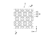
- FIG. 1 is a top view showing a first embodiment of the article of the present invention
- FIG. 2 is a cross-sectional view taken along the line II-II in FIG.
- the broken lines in FIG. 1 are hexagonal lattice lines.
- the article 1 has a base material 10 and a resin pattern 28 formed on the surface of the base material 10.
- the resin pattern 28 includes a plurality of regular protrusions 22, a bottom part 24 formed between the protrusions 22, and a wall-like bridge part 26 that connects adjacent protrusions 22 so as to divide the bottom part 24. It consists of a fine relief structure.
- the substrate 10 may be appropriately selected according to the type of the target product, and is not particularly limited. Examples of the material of the substrate 10 include inorganic materials and organic materials.
- the inorganic material examples include glass, quartz, silicon wafer, metal (aluminum, nickel, copper, etc.), metal oxide (sapphire, indium tin oxide, etc.), gallium nitride, silicon nitride, aluminum nitride, lithium niobate, and the like. .
- organic material examples include fluorine resin, silicone resin, acrylic resin, polycarbonate, polyester (polyethylene terephthalate, etc.), polyamide, polyimide, polypropylene, polyethylene, nylon resin, polyphenylene sulfide, triacetyl cellulose, cyclic polyolefin, and the like.
- a surface-treated one may be used in terms of excellent adhesion to the resin pattern 28.
- the surface treatment include primer coating treatment, UV ozone treatment, plasma etching treatment, and the like.
- the primer include polymethyl methacrylate, silane coupling agent, silazane, polyvinyl alcohol and the like.
- the resin pattern 28 is a pattern formed by removing unnecessary portions from the photosensitive resin layer described later, and including a portion where the resin is not removed and a portion where the resin is removed.
- the protrusions 22 are formed so as to be separated from each other via the bridge portion 26.
- the shape of the protrusion 22 is not limited to the bullet shape (bell shape) as shown in the illustrated example, and may be a cylindrical shape, a prism shape, a conical shape, a pyramid shape, a semicircular shape, or the like.
- the bottom portion 24 is a substantially flat portion formed between the protrusions 22. Usually, it is the surface of the base material 10.
- the bottom 24 may contain a residue of the photosensitive resin layer that could not be removed.
- the bridge portion 26 is a wall-like portion that connects the adjacent protrusions 22 in the lattice line direction so as to divide the bottom portion 24.
- the bridge portion 26 is a portion extending radially from the center of the protrusion 22, and is clearly distinguished from the protrusion 22.
- the average pitch of the protrusions 22 is preferably 80 to 700 nm, and more preferably 160 to 400 nm. If the average pitch of the protrusions 22 is equal to or greater than the lower limit value, the width of the protrusions 22 can be sufficiently secured, so that the protrusions 22 are more difficult to break and the scratch resistance of the fine concavo-convex structure is further improved. When the average pitch of the protrusions 22 is equal to or less than the upper limit value, sufficient antireflection performance due to the fine uneven structure can be obtained.
- the average width of the protrusions 22 is preferably 50% or more of the average pitch, and more preferably 60% or more and 90% or less of the average pitch.
- the average width of the protrusions 22 is equal to or greater than the lower limit, the protrusions 22 are more difficult to break, the scratch resistance of the fine uneven structure is further improved, and the flat bottom 24 can be reduced, so that the antireflection effect can be increased. If the average width of the protrusions 22 is equal to or less than the upper limit value, the bridge portion 26 can be formed.
- the average height of the protrusions 22 is preferably 50% or more and 300% or less of the average pitch, and more preferably 70% or more and 250% or less of the average pitch. If the average height of the protrusions 22 is equal to or greater than the lower limit, sufficient antireflection performance due to the fine uneven structure can be obtained. If the average height of the protrusions 22 is equal to or less than the upper limit, the protrusions 22 are more difficult to break, and the scratch resistance of the fine concavo-convex structure is further improved.
- the average width of the bridge portion 26 is preferably 40 to 300 nm, and more preferably 100 to 200 nm. If the average width of the bridge portion 26 is equal to or greater than the lower limit value, the bridge portion 26 is not easily broken, and the scratch resistance of the fine uneven structure is further improved. If the average width of the bridge portion 26 is equal to or less than the upper limit value, sufficient antireflection performance due to the fine uneven structure can be obtained.
- the average height of the bridge portion 26 is preferably lower than the average height of the protrusions 22, and more preferably 30 to 60% of the average height of the protrusions 22. If the average height of the bridge portion 26 is lower than the average height of the protrusions 22, sufficient antireflection performance due to the fine uneven structure can be obtained. If the average height of the bridge portion 26 is 30% or more of the height of the protrusion 22, the protrusion 22 is more difficult to break, and the scratch resistance of the fine concavo-convex structure is further improved.
- the protrusions 22 may be arranged in a hexagonal lattice shape or a tetragonal lattice shape.
- the protrusions 22 are preferably arranged in a hexagonal lattice form and are periodically arranged in a regular hexagonal lattice form in that the protrusions 22 are more difficult to break and the scratch resistance of the fine concavo-convex structure is further excellent. Is more preferable.
- the bridge portion 26 has three-way lattice lines of a hexagonal lattice as shown in the example from the point that the protrusions 22 are more difficult to break, the scratch resistance of the fine concavo-convex structure is further excellent, and the bridge portion 26 is easily formed.
- the lattice lines in the X direction are symmetrical with respect to the lattice lines in the other two directions with respect to the lattice lines in the X direction.
- the bridge portions 26 are formed in parallel with each other along only lattice lines in one direction, the scratch resistance of the fine concavo-convex structure is inferior to that of the illustrated example.
- the bridge portion 26 is formed along all the lattice lines in the three directions, the area between the valleys in the fine concavo-convex structure is reduced, so that it is difficult to obtain sufficient antireflection performance.
- FIG. 3 is a top view showing a second embodiment of the article of the present invention
- FIG. 4 is a sectional view taken along line IV-IV in FIG.
- the broken lines in FIG. 3 are hexagonal lattice lines.
- the article 2 corresponds to that obtained by etching the article 1 according to the first embodiment.
- the article 2 includes a base material 10 on which a fine uneven structure 18 is directly formed on the surface.
- the fine concavo-convex structure 18 includes a plurality of regular protrusions 12, a bottom part 14 formed between the protrusions 12, and a wall-like bridge part 16 that connects adjacent protrusions 12 so as to divide the bottom part 14.
- the fine concavo-convex structure 18 includes a plurality of regular protrusions 12, a bottom part 14 formed between the protrusions 12, and a wall-like bridge part 16 that connects adjacent protrusions 12 so as to divide the bottom part 14.
- the shape, size, arrangement, and the like of the protrusion 12, the bottom portion 14, and the bridge portion 16 are the same as the shape, size, arrangement, and the like of the protrusion 22, the bottom portion 24, and the bridge portion 26 according to the first embodiment. It is the same.
- the article of the present invention has a fine concavo-convex structure having a plurality of regular protrusions, a bottom formed between the protrusions, and a bridge portion connecting adjacent protrusions so as to divide the bottom on the surface. What is necessary is just to have, and it is not limited to the goods 1 which concern on 1st Embodiment of illustration example, and the goods 2 which concern on 2nd Embodiment.
- a method for manufacturing an article having a fine concavo-convex structure on a surface thereof according to the present invention includes a plurality of regular protrusions, a bottom formed between the protrusions, and the bottom.
- a method of manufacturing an article having a fine concavo-convex structure on the surface having a bridge portion that connects adjacent protrusions so as to divide includes the following step (a), step (b), and, if necessary, step ( c).
- the light corresponding to the fine concavo-convex structure is irradiated by irradiating the photosensitive resin layer of the substrate with the photosensitive resin layer with light from the light irradiation means through a photomask having a regular dot pattern. Forming an image pattern on the photosensitive resin layer;
- a step of obtaining an article (corresponding to the article according to the first embodiment of the present invention).
- step (C) If necessary, after the step (b), the fine concavo-convex structure in which the fine concavo-convex structure is directly formed on the surface of the substrate by etching the substrate on which the resin pattern is formed on the surface.
- a step of obtaining an article having a surface thereof (corresponding to an article according to the second embodiment of the present invention).
- a mask 30 is disposed.
- the light irradiation means 40 is disposed above the photomask 30 so that the longitudinal direction is the Y direction. Irradiating the photosensitive resin layer 20 of the substrate with the photosensitive resin layer through the photomask 30 while moving the light irradiation means 40 in the X direction orthogonal to the Y direction.
- a latent image pattern corresponding to the fine concavo-convex structure is formed on the photosensitive resin layer 20.
- the photosensitive resin layer 20 is not particularly limited as long as it can form a latent image pattern by light irradiation in photolithography.
- Examples of the material for forming the photosensitive resin layer 20 include known photosensitive resin compositions such as a photoresist.
- the photosensitive resin composition may be a positive type or a negative type.
- the photomask 30 is a photomask using the Talbot effect.
- Examples of the photomask using the Talbot effect include a phase shift mask using the Talbot effect.
- the photomask 30 has a regular dot pattern for forming a plurality of projections having a fine concavo-convex structure formed on the surface of an article finally obtained.
- the photomask 30 has dots having different optical path lengths.
- the arrangement of the dot pattern of the photomask and the arrangement of the plurality of protrusions of the finally obtained article are not necessarily one-to-one.
- Examples of the photomask 30 include those in which dots in a dot pattern are arranged in a hexagonal lattice, and those in which a dot is arranged in a tetragonal lattice. From the point that the protrusions in the finally obtained article are more difficult to break and the scratch resistance of the fine concavo-convex structure is further excellent, it is preferable that the dots in the dot pattern are arranged in a hexagonal lattice, and the dots are in a regular hexagonal lattice Those arranged periodically are more preferable.
- the shape of the photomask 30 is not limited to the planar shape in the illustrated example, and may be a roll shape, a belt shape, or the like.
- the spread angle in one direction (for example, the Y direction) parallel to the surface of the photomask 30 is made wider than the spread angle in the other direction (for example, the X direction) parallel to the surface of the photomask 30. It can irradiate light.
- the light spread angle is an angle ⁇ that indicates how much the light diameter at a predetermined distance from the light irradiation means 40 spreads with respect to the exit diameter of the exit surface of the light irradiation means 40.
- an aperture (not shown) with a pinhole having a diameter of 1 mm is attached to the exit surface of the light irradiation means 40, and a photosensitive resin layer (not shown) disposed at a distance of 9 mm from the pinhole outlet.
- the photosensitive resin layer is developed to form a pattern, the pattern diameter R2, the pinhole diameter R1 (1 mm), and from the pinhole exit to the photosensitive resin layer
- the angle ⁇ obtained by the following equation from the distance D (9 mm).
- ⁇ tan ⁇ 1 [ ⁇ (R2-R1) / 2 ⁇ / D]
- the light irradiation means 40 is not limited to the line-shaped illumination in the illustrated example, and may be a planar illumination or the like.
- the light irradiation means includes a normal light source (high pressure mercury lamp, light emitting diode (LED), xenon lamp, mercury xenon lamp, metal halide lamp, deuterium lamp, electrodeless light source, etc.) and optical member (concave mirror, condenser lens) And a combination with a collimation lens (such as a cylindrical lens).
- an LED line array in which a plurality of LEDs (light emitting diodes) are arranged in a line in one direction, and a plano-convex having the same length as the LED line array LED line illumination comprising a cylindrical lens, in which the LED line array and the plano-convex cylindrical lens are arranged in parallel to each other and so that light emitted from the LED line array enters from the plane side of the plano-convex cylindrical lens is preferable.
- the LED line illumination light is collimated in the width direction of the LED line illumination so that the light approaches a parallel state, and light that diffuses without being collimated can be irradiated in the longitudinal direction of the LED line illumination.
- the light to be irradiated is collimated to light whose divergence angle in one direction is wider than the divergence angle in the other direction, for example, one direction (that is, a collimating direction, for example, the X direction).
- one direction that is, a collimating direction, for example, the X direction
- diffused anisotropic light is used.
- the light divergence angle in the collimating direction (for example, the X direction) is preferably 0 to 8 ° and more preferably 0 to 6 ° from the viewpoint of easily forming a bridge portion.
- the spread angle of light in the diffusion direction (for example, Y direction) is preferably 10 to 60 °, more preferably 20 to 45 °, from the viewpoint of easily forming a bridge portion.
- the light irradiation means 40 and the photomask 30 are preferably arranged so that the direction in which the light spread angle is the widest and one direction of the lattice lines of the hexagonal lattice in the dot pattern are orthogonal to each other.
- the light irradiation means 40 whose longitudinal direction is the light diffusion direction and whose width direction is the light collimation direction is used, and the longitudinal direction of the light irradiation means 40 (that is, light 7 is the Y direction, as shown in FIG. 7, the light irradiation means so that one direction of the lattice lines of the hexagonal lattice in the dot pattern of the photomask 30 is the X direction orthogonal to the Y direction. 40 and a photomask 30 are arranged.
- the diffusion direction (Y direction) of the light irradiated from the light irradiation means 40 and the one direction (Y direction) of the hexagonal lattice lines in the dot pattern of the photomask 30 coincide.
- dots are connected in the light diffusion direction (Y direction), and bridge portions are formed in parallel to each other only along the grid lines in the Y direction.
- the black part represents the bottom part.
- the fine concavo-convex structure in which the bridge part is formed symmetrically along the lattice line in two directions is more resistant to scratches than the fine concavo-convex structure in which the bridge part is formed in parallel with each other only along the lattice line in one direction. Excellent in properties.
- the integrated light amount is less than the appropriate light amount, that is, underexposure from the viewpoint of easily forming a bridge portion.
- the integrated light amount is preferably 70 to 90% of the appropriate light amount, and more preferably 75 to 85%.
- the integrated light amount is more than the appropriate light amount, that is, overexposed, from the viewpoint of easily forming a bridge portion.
- the integrated light amount is preferably 115 to 135%, more preferably 120 to 130% of the appropriate light amount.
- the proper light amount means the median value of the light amount range in which the height of the photoresist protrusion to be formed is the highest.
- the development process is performed, for example, by bringing the photosensitive resin layer on which the latent image pattern is formed into contact with the developer.
- the developer is not particularly limited as long as it can remove either the exposed part or the unexposed part in the step (a).
- the substrate with the resin pattern (photoresist pattern) formed on the surface is etched to obtain a fine concavo-convex structure as shown in FIGS. 11 (A) and 11 (B), for example. Is formed directly on the surface of the substrate, and an article having a fine concavo-convex structure on the surface (corresponding to the article according to the second embodiment of the present invention) is obtained.
- the etching process is performed, for example, by bringing a plasma etching gas into contact with the surface of the substrate on which the resin pattern is formed on the surface on which the resin pattern is formed.
- the etching gas may be appropriately selected according to the material of the substrate and the material of the resin pattern.
- the base material When the resin pattern remains on the surface of the base material after the etching treatment, the base material may be treated with a stripping solution or the like. You may process the surface of the base material after an etching process with well-known surface treatment agents, such as a slipperiness
- step (a) a photomask using a Talbot effect having a regular dot pattern and a unidirectional spread angle parallel to the surface of the photomask.
- the photosensitive resin layer is exposed in combination with light that is wider than the spread angle in the other direction parallel to the surface of the photomask. Therefore, not only a latent image pattern corresponding to a plurality of protrusions of an article finally obtained due to a complicated light interference phenomenon, but also a bridge that connects adjacent protrusions so as to divide the bottom formed between the protrusions.
- a latent image pattern corresponding to the bridge portion is also formed.
- the photosensitive resin layer on which the latent image pattern is formed in the step (b) by developing the photosensitive resin layer on which the latent image pattern is formed in the step (b), the plurality of regular protrusions, the bottom formed between the protrusions, and the bottom are separated.
- the resin pattern which consists of a fine concavo-convex structure which has a bridge part which connects between adjacent protrusions is formed.
- a step of forming a latent image pattern corresponding to the fine concavo-convex structure on the photosensitive resin layer and (b) after the step (a), by developing the substrate with the photosensitive resin layer, the fine concavo-convex structure And a step of obtaining an article having a fine concavo-convex structure on the surface, wherein the photomask is a photomask using the Talbot effect, Any light may be used as long as the spread angle in one direction parallel to the surface of the photomask is wider than the spread angle in the other direction parallel to the surface of the photomask. Limited to methods There.
- a mold having a reversal structure of a fine concavo-convex structure formed on the surface is produced, and the reversal structure is applied to the surface of a substrate to be transferred by an imprint method using the mold.
- an article having a fine concavo-convex structure on the surface may be obtained.
- electroforming or nanoimprinting on the surface of the fine concavo-convex structure produced by steps (a) and (b), a plurality of holes and a flat portion formed between the holes, Then, it is possible to produce a mold having a reverse structure formed on the surface having a groove portion connecting adjacent holes so as to divide the flat portion.
- Examples 1 and 2 are examples, and example 3 is a comparative example.
- 1,1,1,3,3,3-hexamethyldisilazane (Tokyo Ohka Kogyo Co., Ltd., OAP) is dropped on the center of the surface of the synthetic quartz substrate, and a spin coater (Mikasa Co., Ltd., 1H-DX2) is used. Then, spin coating was performed at 25 ° C. and 3000 rpm for 20 seconds. The synthetic quartz substrate was heated on a hot plate at 130 ° C. for 180 seconds to obtain a surface-treated synthetic quartz substrate.
- a positive-type photoresist (AZ Electronics, AZ-7904) is dropped on the center of the surface of the surface-treated synthetic quartz substrate, and the spin coater (Mikasa, 1H-DX2) is used at 25 ° C. and 3000 rpm. Spin coating was performed for 20 seconds.
- the synthetic quartz substrate was heated on a hot plate at 90 ° C. for 180 seconds to obtain a synthetic quartz substrate with a photoresist film having a thickness of 430 nm (base material with a photosensitive resin layer).
- a phase shift mask using the Talbot effect shown in FIG. 7 on the surface of the synthetic quartz substrate with a photoresist film (dot arrangement: regular hexagonal lattice, dot pitch: 600 nm, dot diameter: 300 nm) Are arranged such that one direction of the hexagonal lattice line in the dot pattern is the X direction.
- LED line illumination manufactured by ITEC System, main wavelength: 365 nm, light spreading angle in the width direction (X direction, collimating direction): 6 °, longitudinal direction (Y direction, The light spread angle in the diffusion direction (45 °) was arranged so that the longitudinal direction was the Y direction.
- the distance from the exit surface of the LED line illumination to the photoresist film was 9 mm.
- the synthetic quartz substrate was rinsed with pure water and dried by air blow to obtain a synthetic quartz substrate with a photoresist pattern shown in FIG.
- the average pitch of the protrusions in the resist pattern is 600 nm
- the average width of the protrusions is 370 nm
- the average height of the protrusions is 450 nm
- the average width of the bridge portion is 150 nm
- the average height of the bridge portion is It was 200 nm.
- NLD-500 high-density plasma etching apparatus
- the average pitch of the protrusions in the fine concavo-convex structure is 600 nm, the average width of the protrusions is 350 nm, the average height of the protrusions is 330 nm, the average width of the bridge portion is 130 nm, and the average height of the bridge portion was 180 nm.
- the obtained article was immersed in a treatment solution obtained by diluting a surface treatment agent (manufactured by Daikin Industries, Ltd., OPTOOL DSX) to 0.1% by mass with perfluorohexane at room temperature for 1 minute. After pulling up the article, it was allowed to stand for 1 hour under conditions of 60 ° C. and 90% RH to obtain an article for a flannel rubbing test. Three such articles were prepared, and a flannel rubbing test was performed in each of the X direction, the Y direction, and the oblique direction. The results are shown in FIGS. 13 (A), 13 (B), and 13 (C). No streak-like scratches appeared in the rubbing direction.
- a surface treatment agent manufactured by Daikin Industries, Ltd., OPTOOL DSX
- Example 2 A synthetic quartz substrate with a photoresist pattern shown in FIG. 10 in the same manner as in Example 1 except that the phase shift mask using the Talbot effect is arranged so that one direction of the hexagonal lattice line in the dot pattern is the Y direction. Got.
- the average pitch of the protrusions in the resist pattern is 600 nm
- the average width of the protrusions is 350 nm
- the average height of the protrusions is 450 nm
- the average width of the bridge portion is 180 nm
- the average height of the bridge portion is It was 230 nm.
- Example 3 The LED line illumination of Example 1 is a UV exposure apparatus (manufactured by Quintel, UL-7000, main wavelength: 365 nm, light spread angle in the width direction (X direction): 4 °, light spread angle in the longitudinal direction (Y direction) : 4 °), and an article having a fine concavo-convex structure shown in FIGS. 14 (A) and 14 (B) was obtained in the same manner as in Example 1 except that the integrated light quantity was changed to 17 mJ / cm 2 . .
- the average pitch of the protrusions in the fine concavo-convex structure was 600 nm, the average width of the protrusions was 335 nm, and the average height of the protrusions was 450 nm. No bridge was formed.
- the article was etched and surface-treated in the same manner as in Example 1 to obtain an article for a fretting rub test.
- Three such articles were prepared, and a flannel rubbing test was performed in each of the X direction, the Y direction, and the oblique direction. The results are shown in FIGS. 15 (A), 15 (B), and 15 (C). A streak-like scratch appeared in the rubbing direction.
- the article having the fine concavo-convex structure of the present invention on the surface is useful as an antireflection member, a light extraction member, a heat radiating member, a surface catalyst, a hydrophilic member, a water repellent member, an antifouling member, and the like.
Abstract
The purpose of the present invention is to provide a method that makes it easy to produce an article which has on a surface thereof a fine uneven structure and which is superior in abrasion resistance. Provided is a method for producing an article having on a surface thereof a resin pattern 28 (fine uneven structure) that has a plurality of regular projections 22 and bridge sections 26 that each form a link between adjacent projections 22 so as to demarcate bottom sections 24 formed between the projections 22. The method comprises: (a) a step for irradiating a photosensitive resin layer of a substrate equipped with the photosensitive resin layer with light from a light radiating means, via a photomask having a regular dot pattern; and (b) a step for developing the substrate equipped with the photosensitive resin layer, thereby obtaining an article having a resin pattern 28 (fine uneven structure) on a surface thereof. The photomask makes use of the Talbot effect, and the light from the light radiating means has a spread angle in one direction that is broader than a spread angle in another direction.
Description
本発明は、微細凹凸構造を表面に有する物品およびその製造方法に関する。
The present invention relates to an article having a fine concavo-convex structure on its surface and a method for producing the same.
周期が可視光の波長以下である複数の突起からなる微細凹凸構造を表面に有する物品は、反射防止性能に優れることが知られている。
しかし、微細凹凸構造における突起が根元から折れやすく、微細凹凸構造を表面に有する物品は、耐擦傷性が不充分である。 It is known that an article having a fine concavo-convex structure composed of a plurality of protrusions whose period is not more than the wavelength of visible light on the surface is excellent in antireflection performance.
However, the protrusions in the fine concavo-convex structure are easily broken from the base, and the article having the fine concavo-convex structure on the surface is insufficient in scratch resistance.
耐擦傷性が向上した微細凹凸構造を表面に有する物品としては、下記のものが提案されている。
・周期が可視光の波長以下である微小突起が密接して配置され、微小突起の少なくとも一部が頂点を複数有する多峰性微小突起であり、残りが単峰性微小突起である反射防止物品(特許文献1参照)。 The following are proposed as articles having a fine concavo-convex structure with improved scratch resistance on the surface.
・ Anti-reflective article in which microprotrusions whose period is equal to or less than the wavelength of visible light are closely arranged, at least a part of the microprotrusions are multimodal microprotrusions having a plurality of vertices, and the rest are unimodal microprotrusions (See Patent Document 1).
特許文献1の反射防止物品は、多峰性微小突起および単峰性微小突起に対応する微細穴を表面に有する金型を用いたナノインプリント法によって製造される。
しかし、表面の形状が複雑な金型は、作製が難しい。そのため、特許文献1の反射防止物品は、簡便に製造できないという問題を有する。 The antireflective article ofPatent Document 1 is manufactured by a nanoimprint method using a mold having fine holes on the surface corresponding to multimodal microprojections and monomodal microprojections.
However, it is difficult to manufacture a mold having a complicated surface shape. Therefore, the antireflective article ofpatent document 1 has the problem that it cannot manufacture easily.
しかし、表面の形状が複雑な金型は、作製が難しい。そのため、特許文献1の反射防止物品は、簡便に製造できないという問題を有する。 The antireflective article of
However, it is difficult to manufacture a mold having a complicated surface shape. Therefore, the antireflective article of
本発明は、耐擦傷性に優れる微細凹凸構造を表面に有する物品を簡便に製造できる方法;および、耐擦傷性に優れる微細凹凸構造を表面に有する物品を提供する。
The present invention provides a method capable of easily producing an article having a fine concavo-convex structure excellent in scratch resistance on the surface; and an article having a fine concavo-convex structure excellent in scratch resistance on the surface.
本発明は、以下の態様を有する。
[1]規則性を有する複数の突起と、該突起間に形成された底部と、該底部を区切るように隣り合う突起間を連結する橋架け部とを有する微細凹凸構造を表面に有する物品を製造する方法であって、(a)光照射手段からの光を、規則性を有するドットパターンを有するフォトマスクを介して、感光性樹脂層付き基材の感光性樹脂層に照射することによって、前記微細凹凸構造に対応する潜像パターンを前記感光性樹脂層に形成する工程と、(b)前記工程(a)の後、前記感光性樹脂層付き基材を現像処理することによって、前記微細凹凸構造に対応する樹脂パターンが前記基材の表面に形成された、前記微細凹凸構造を表面に有する物品を得る工程とを有し、前記フォトマスクが、タルボ効果を利用したフォトマスクであり、前記光照射手段からの光が、前記フォトマスクの表面に平行な一方向の広がり角が、前記フォトマスクの表面に平行な他の方向の広がり角よりも広くされた光である、微細凹凸構造を表面に有する物品の製造方法。
[2](c)前記工程(b)の後、前記樹脂パターンが表面に形成された前記基材をエッチング処理することによって、前記微細凹凸構造が前記基材の表面に直接形成された、前記微細凹凸構造を表面に有する物品を得る工程をさらに有する、[1]の微細凹凸構造を表面に有する物品の製造方法。
[3]前記光照射手段が、ライン状に並べた複数の発光ダイオード(LED)と平凸シリンドリカルレンズとを備えたLEDライン照明である、[1]または[2]の微細凹凸構造を表面に有する物品の製造方法。
[4]前記ドットパターンにおけるドットが、六方格子状に配列されている、[1]~[3]のいずれかの微細凹凸構造を表面に有する物品の製造方法。
[5]前記光の広がり角が最も広くされた方向と前記ドットパターンにおける六方格子の格子線の一方向とが直交するように、前記光照射手段および前記フォトマスクが配置されている、[4]の微細凹凸構造を表面に有する物品の製造方法。
[6]前記光照射手段から照射される光が、前記フォトマスクの表面に平行な一方向の広がり角が10°~60°であり、前記フォトマスクの表面に平行な一方向に直行する方向の広がり角が0~8°に設定された光である、[1]~[5]のいずれかの微細凹凸構造を表面に有する物品の製造方法。
[7]前記フォトマスクが、タルボ効果を利用した位相シフトマスクである、[1]~[6]のいずれかの微細凹凸構造を表面に有する物品の製造方法。
[8]規則性を有する複数の突起と、該突起間に形成された底部と、該底部を区切るように隣り合う突起間を連結する橋架け部とを有する微細凹凸構造を表面に有する物品。
[9]前記橋架け部の平均高さが、前記突起の平均高さよりも低くされた、[8]の微細凹凸構造を表面に有する物品。
[10]前記突起が、六方格子状に配列されている、[8]または[9]の微細凹凸構造を表面に有する物品。
[11]前記橋架け部が、六方格子の三方向の格子線のうち、一方向の格子線を対称軸として他の二方向の格子線に沿って線対称に形成されている、[10]の微細凹凸構造を表面に有する物品。 The present invention has the following aspects.
[1] An article having a fine concavo-convex structure on the surface having a plurality of regular protrusions, a bottom portion formed between the protrusions, and a bridge portion connecting adjacent protrusions so as to divide the bottom portion. (A) by irradiating the photosensitive resin layer of the substrate with the photosensitive resin layer with light from the light irradiation means via a photomask having a regular dot pattern, A step of forming a latent image pattern corresponding to the fine concavo-convex structure on the photosensitive resin layer; and (b) after the step (a), by developing the substrate with the photosensitive resin layer, A resin pattern corresponding to the concavo-convex structure is formed on the surface of the base material, and a step of obtaining an article having the fine concavo-convex structure on the surface, and the photomask is a photomask using a Talbot effect, Light irradiation The light from the step is light having a divergence angle in one direction parallel to the surface of the photomask wider than that in the other direction parallel to the surface of the photomask. A method of manufacturing an article having
[2] (c) After the step (b), the fine concavo-convex structure is directly formed on the surface of the substrate by etching the substrate on which the resin pattern is formed. The method for producing an article having the fine uneven structure according to [1], further comprising a step of obtaining an article having a fine uneven structure on the surface.
[3] The light irradiating means is LED line illumination including a plurality of light emitting diodes (LEDs) arranged in a line and a plano-convex cylindrical lens, and the fine uneven structure according to [1] or [2] is provided on the surface. A method of manufacturing an article having
[4] A method for manufacturing an article having the fine uneven structure according to any one of [1] to [3] on a surface, in which dots in the dot pattern are arranged in a hexagonal lattice pattern.
[5] The light irradiation means and the photomask are arranged so that the direction in which the light spread angle is widest and one direction of the lattice lines of the hexagonal lattice in the dot pattern are orthogonal to each other. ] The manufacturing method of the articles | goods which have the fine concavo-convex structure on the surface.
[6] A direction in which light emitted from the light irradiating means has a divergence angle in one direction parallel to the surface of the photomask of 10 ° to 60 °, and is orthogonal to the direction parallel to the surface of the photomask. A method for producing an article having on its surface a fine concavo-convex structure according to any one of [1] to [5], which is light having a spread angle of 0 to 8 °.
[7] A method for manufacturing an article having the fine concavo-convex structure of any one of [1] to [6] on the surface, wherein the photomask is a phase shift mask using a Talbot effect.
[8] An article having a fine concavo-convex structure on the surface having a plurality of regular protrusions, a bottom formed between the protrusions, and a bridge portion connecting adjacent protrusions so as to divide the bottom.
[9] An article having the fine concavo-convex structure of [8] on the surface, wherein an average height of the bridge portion is lower than an average height of the protrusions.
[10] An article having the fine concavo-convex structure of [8] or [9] on the surface, wherein the protrusions are arranged in a hexagonal lattice pattern.
[11] The bridge portion is formed in line symmetry along the lattice line in the other two directions with respect to the lattice line in one direction among the lattice lines in the three directions of the hexagonal lattice. [10] An article having a fine uneven structure on its surface.
本発明の微細凹凸構造を表面に有する物品の製造方法によれば、耐擦傷性に優れ、さらに反射防止性能に優れた微細凹凸構造を表面に有する物品を簡便に製造できる。
本発明の微細凹凸構造を表面に有する物品は、微細凹凸構造の耐擦傷性に優れる。 According to the method for producing an article having a fine concavo-convex structure on the surface of the present invention, an article having a fine concavo-convex structure on the surface which is excellent in scratch resistance and excellent in antireflection performance can be easily produced.
The article having the fine concavo-convex structure of the present invention on the surface is excellent in scratch resistance of the fine concavo-convex structure.
以下の用語の定義は、本明細書および特許請求の範囲にわたって適用される。
「光」とは、紫外線、γ線、X線、電子線等の総称である。
「フォトマスク」とは、フォトリソグラフィにおけるパターン原版、すなわちこれを介して感光性樹脂層に光を照射した際に、感光性樹脂層をパターン状に露光し得るものを意味する。
「潜像パターン」とは、感光性樹脂層において露光された部分と露光されなかった部分とからなるパターンである。現像処理によって露光された部分および露光されなかった部分のいずれか一方が除去されることによって、所望の樹脂パターンが形成される。
「タルボ(Talbot)効果」とは、周期的なマスクパターンを有するフォトマスクに光を照射したとき、フォトマスクから特定の距離において干渉パターンが形成される現象を意味する。
「タルボ効果を利用した位相シフトマスク」とは、光路長が異なる部分をパターン状に形成した透明なマスクで、光路長の違いによって位相を部分的に変化させることで、出てくる光に回折干渉(タルボ効果)を発生させて感光性樹脂層中にパターンを形成するフォトマスクを意味する。
「広がり角」とは、光照射手段の出射面に直径1mmのピンホールが穿設されたアパーチャを取り付け、ピンホール出口から9mmの距離に配置された感光性樹脂層にピンホールを通過した光を照射し、感光性樹脂層を現像処理してパターン(感光性樹脂組成物がポジ型の場合は穴)を形成し、パターンの直径R2と、ピンホールの直径R1(1mm)と、ピンホール出口から感光性樹脂層までの距離D(9mm)とから下式で求めた角度θを意味する。
θ=tan-1[{(R2-R1)/2}/D]
「平凸シリンドリカルレンズ」とは、円柱を軸方向に割った形状のレンズであって、幅方向には曲率を持つが長手方向(円柱の軸方向)には曲率を持たないシリンドリカル面(円筒面)と、該シリンドリカル面に対向する平面とを有するレンズを意味する。
「ドット(または突起)が六方格子(または四方格子)状に配列されている」とは、六方格子(または四方格子)の格子点にドット(または突起)が位置するように、ドット(または突起)が配列されていることを意味する。
「ドット(または突起)が正六方格子状に周期的に配置されている」とは、最外側のドット(または突起)を除く任意のドット(または突起)の周囲に、該任意のドット(または突起)からの距離が最も近くかつ等しい6個のドット(または突起)が配置されることを意味する。6個のドット(または突起)の頂点は、前記任意のドット(または突起)の頂点を中心に60°間隔で等ピッチで配置され、正六角形状の格子を構成する。
「格子線」とは、隣接する格子点間を結ぶ線を意味する。
「突起のピッチ」とは、格子線方向で隣接する突起の中心間距離を意味し、「突起の平均ピッチ」とは、無作為に選ばれた6箇所の突起のピッチの平均値を意味する。
「突起の幅」とは、突起の底面における最大長さを意味し、「突起の平均幅」とは、無作為に選ばれた6個の突起の幅の平均値を意味する。
「突起の高さ」とは、突起の底面から頂点までの高さを意味し、「突起の平均高さ」とは、無作為に選ばれた6個の突起の高さの平均値を意味する。
「橋架け部の幅」とは、橋架け部の格子線に直交する断面における最大長さを意味し、「橋架け部の平均幅」とは、無作為に選ばれた6個の橋架け部の幅の平均値を意味する。
「橋架け部の高さ」とは、橋架け部の底面から最も高い部分までの高さを意味し、「橋架け部の平均高さ」とは、無作為に選ばれた6個の橋架け部の高さの平均値を意味する。 The following definitions of terms apply throughout this specification and the claims.
“Light” is a general term for ultraviolet rays, γ-rays, X-rays, electron beams, and the like.
The “photomask” means a pattern original plate in photolithography, that is, one that can expose the photosensitive resin layer in a pattern when the photosensitive resin layer is irradiated with light.
The “latent image pattern” is a pattern composed of an exposed portion and an unexposed portion in the photosensitive resin layer. A desired resin pattern is formed by removing one of the exposed portion and the unexposed portion by the development process.
The “Talbot effect” means a phenomenon in which an interference pattern is formed at a specific distance from a photomask when light is irradiated onto the photomask having a periodic mask pattern.
A “phase shift mask that uses the Talbot effect” is a transparent mask in which parts with different optical path lengths are formed in a pattern. The phase is partially changed by the difference in optical path length, and is diffracted into the emitted light. It means a photomask that forms a pattern in a photosensitive resin layer by generating interference (Talbot effect).
“Diverging angle” refers to light that has passed through a pinhole on a photosensitive resin layer that is disposed at a distance of 9 mm from the pinhole exit by attaching an aperture having a 1 mm diameter pinhole formed on the exit surface of the light irradiation means. , The photosensitive resin layer is developed to form a pattern (a hole when the photosensitive resin composition is positive), a pattern diameter R2, a pinhole diameter R1 (1 mm), and a pinhole It means the angle θ obtained by the following formula from the distance D (9 mm) from the exit to the photosensitive resin layer.
θ = tan −1 [{(R2-R1) / 2} / D]
A “plano-convex cylindrical lens” is a lens having a cylindrical shape divided in the axial direction, and has a cylindrical surface (cylindrical surface) that has a curvature in the width direction but no curvature in the longitudinal direction (axial direction of the cylinder). ) And a plane opposite to the cylindrical surface.
“Dots (or protrusions) are arranged in a hexagonal lattice (or tetragonal lattice)” means that the dots (or protrusions) are located at the lattice points of the hexagonal lattice (or tetragonal lattice). ) Is arranged.
“The dots (or protrusions) are periodically arranged in a regular hexagonal lattice” means that any dot (or protrusion) other than the outermost dot (or protrusion) is surrounded by any dot (or protrusion). This means that six dots (or projections) that are closest and equal in distance from the projection) are arranged. The vertices of the six dots (or protrusions) are arranged at an equal pitch at an interval of 60 ° around the vertex of the arbitrary dot (or protrusion) to constitute a regular hexagonal lattice.
“Lattice line” means a line connecting adjacent lattice points.
“Protrusion pitch” means the distance between the centers of adjacent protrusions in the lattice line direction, and “protrusion average pitch” means the average value of the pitches of six randomly selected protrusions. .
“Protrusion width” means the maximum length of the bottom surface of the protrusion, and “average width of the protrusion” means an average value of the widths of six randomly selected protrusions.
“Protrusion height” means the height from the bottom of the protrusion to the apex, and “Average protrusion height” means the average height of six randomly selected protrusions. To do.
“Bridge width” means the maximum length of the cross section perpendicular to the grid line of the bridge, and “average width of the bridge” means 6 bridges selected at random. Means the average width of the part.
“The height of the bridge” means the height from the bottom of the bridge to the highest part, and the “average height of the bridge” means six randomly selected bridges Means the average height of the bridge.
<物品>
本発明の微細凹凸構造を表面に有する物品(以下、単に物品とも記す。)は、規則性を有する複数の突起と、該突起間に形成された底部と、該底部を区切るように隣り合う突起間を連結する橋架け部とを有する微細凹凸構造を表面に有する。 <Article>
An article having a fine concavo-convex structure on a surface thereof (hereinafter, also simply referred to as an article) of the present invention includes a plurality of regular protrusions, a bottom formed between the protrusions, and a protrusion adjacent to the bottom. It has a fine concavo-convex structure on the surface, which has a bridge portion connecting between them.
(第1実施形態)
図1は、本発明の物品の第1実施形態を示す上面図であり、図2は、図1のII-II断面図である。図1中の破線は、六方格子の格子線である。
物品1は、基材10と、基材10の表面に形成された樹脂パターン28とを有する。樹脂パターン28は、規則性を有する複数の突起22と、突起22間に形成された底部24と、底部24を区切るように隣り合う突起22間を連結する壁状の橋架け部26とを有する微細凹凸構造からなる。 (First embodiment)
FIG. 1 is a top view showing a first embodiment of the article of the present invention, and FIG. 2 is a cross-sectional view taken along the line II-II in FIG. The broken lines in FIG. 1 are hexagonal lattice lines.
Thearticle 1 has a base material 10 and a resin pattern 28 formed on the surface of the base material 10. The resin pattern 28 includes a plurality of regular protrusions 22, a bottom part 24 formed between the protrusions 22, and a wall-like bridge part 26 that connects adjacent protrusions 22 so as to divide the bottom part 24. It consists of a fine relief structure.
図1は、本発明の物品の第1実施形態を示す上面図であり、図2は、図1のII-II断面図である。図1中の破線は、六方格子の格子線である。
物品1は、基材10と、基材10の表面に形成された樹脂パターン28とを有する。樹脂パターン28は、規則性を有する複数の突起22と、突起22間に形成された底部24と、底部24を区切るように隣り合う突起22間を連結する壁状の橋架け部26とを有する微細凹凸構造からなる。 (First embodiment)
FIG. 1 is a top view showing a first embodiment of the article of the present invention, and FIG. 2 is a cross-sectional view taken along the line II-II in FIG. The broken lines in FIG. 1 are hexagonal lattice lines.
The
基材10は、目的とする製品の種類に応じて適宜選定すればよく、特に限定されない。基材10の材質としては、無機材料または有機材料が挙げられる。
The substrate 10 may be appropriately selected according to the type of the target product, and is not particularly limited. Examples of the material of the substrate 10 include inorganic materials and organic materials.
無機材料としては、ガラス、石英、シリコンウェハ、金属(アルミニウム、ニッケル、銅等)、金属酸化物(サファイア、酸化インジウムスズ等)、窒化ガリウム、窒化珪素、窒化アルミニウム、ニオブ酸リチウム等が挙げられる。
Examples of the inorganic material include glass, quartz, silicon wafer, metal (aluminum, nickel, copper, etc.), metal oxide (sapphire, indium tin oxide, etc.), gallium nitride, silicon nitride, aluminum nitride, lithium niobate, and the like. .
有機材料としては、フッ素樹脂、シリコーン樹脂、アクリル樹脂、ポリカーボネート、ポリエステル(ポリエチレンテレフタレート等)、ポリアミド、ポリイミド、ポリプロピレン、ポリエチレン、ナイロン樹脂、ポリフェニレンサルファイド、トリアセチルセルロース、環状ポリオレフィン等が挙げられる。
Examples of the organic material include fluorine resin, silicone resin, acrylic resin, polycarbonate, polyester (polyethylene terephthalate, etc.), polyamide, polyimide, polypropylene, polyethylene, nylon resin, polyphenylene sulfide, triacetyl cellulose, cyclic polyolefin, and the like.
基材10としては、樹脂パターン28との密着性に優れる点から、表面処理されたものを用いてもよい。表面処理としては、プライマ塗布処理、UVオゾン処理、プラズマエッチング処理等が挙げられる。プライマとしては、ポリメチルメタクリレート、シランカップリング剤、シラザン、ポリビニルアルコール等が挙げられる。
As the base material 10, a surface-treated one may be used in terms of excellent adhesion to the resin pattern 28. Examples of the surface treatment include primer coating treatment, UV ozone treatment, plasma etching treatment, and the like. Examples of the primer include polymethyl methacrylate, silane coupling agent, silazane, polyvinyl alcohol and the like.
樹脂パターン28は、後述する感光性樹脂層から不要部分を除去して形成される、樹脂が除去されなかった部分と樹脂が除去された部分とからなるパターンである。
The resin pattern 28 is a pattern formed by removing unnecessary portions from the photosensitive resin layer described later, and including a portion where the resin is not removed and a portion where the resin is removed.
突起22は、橋架け部26を介して互いに離間して形成される。突起22の形状は、図示例のような砲弾形(釣鐘形)に限定されず、円柱形、角柱形、円錐形、角錐形、半円形等であってもよい。
The protrusions 22 are formed so as to be separated from each other via the bridge portion 26. The shape of the protrusion 22 is not limited to the bullet shape (bell shape) as shown in the illustrated example, and may be a cylindrical shape, a prism shape, a conical shape, a pyramid shape, a semicircular shape, or the like.
底部24は、突起22間に形成される略平坦な部分である。通常は、基材10の表面である。底部24には、除去しきれなかった感光性樹脂層の残渣が存在していてもよい。
The bottom portion 24 is a substantially flat portion formed between the protrusions 22. Usually, it is the surface of the base material 10. The bottom 24 may contain a residue of the photosensitive resin layer that could not be removed.
橋架け部26は、底部24を区切るように格子線方向で隣り合う突起22間を連結する壁状の部分である。橋架け部26は、突起22の中心から見て放射状に延びる部分であり、突起22とは明確に区別される。
The bridge portion 26 is a wall-like portion that connects the adjacent protrusions 22 in the lattice line direction so as to divide the bottom portion 24. The bridge portion 26 is a portion extending radially from the center of the protrusion 22, and is clearly distinguished from the protrusion 22.
突起22の平均ピッチは、80~700nmが好ましく、160~400nmがより好ましい。突起22の平均ピッチが前記下限値以上であれば、突起22の幅を充分に確保できるため、突起22がさらに折れにくく、微細凹凸構造の耐擦傷性がさらに優れる。突起22の平均ピッチが前記上限値以下であれば、微細凹凸構造による充分な反射防止性能が得られる。
The average pitch of the protrusions 22 is preferably 80 to 700 nm, and more preferably 160 to 400 nm. If the average pitch of the protrusions 22 is equal to or greater than the lower limit value, the width of the protrusions 22 can be sufficiently secured, so that the protrusions 22 are more difficult to break and the scratch resistance of the fine concavo-convex structure is further improved. When the average pitch of the protrusions 22 is equal to or less than the upper limit value, sufficient antireflection performance due to the fine uneven structure can be obtained.
突起22の平均幅は、平均ピッチの50%以上が好ましく、平均ピッチの60%以上、90%以下がより好ましい。突起22の平均幅が前記下限値以上であれば、突起22がさらに折れにくく、微細凹凸構造の耐擦傷性がさらに優れる上に、平坦な底部24を少なくできるため、反射防止効果を大きくできる。突起22の平均幅が前記上限値以下であれば、橋架け部26を形成できる。
The average width of the protrusions 22 is preferably 50% or more of the average pitch, and more preferably 60% or more and 90% or less of the average pitch. When the average width of the protrusions 22 is equal to or greater than the lower limit, the protrusions 22 are more difficult to break, the scratch resistance of the fine uneven structure is further improved, and the flat bottom 24 can be reduced, so that the antireflection effect can be increased. If the average width of the protrusions 22 is equal to or less than the upper limit value, the bridge portion 26 can be formed.
突起22の平均高さは、平均ピッチの50%以上、300%以下が好ましく、平均ピッチの70%以上、250%以下がより好ましい。突起22の平均高さが前記下限値以上であれば、微細凹凸構造による充分な反射防止性能が得られる。突起22の平均高さが前記上限値以下であれば、突起22がさらに折れにくく、微細凹凸構造の耐擦傷性がさらに優れる。
The average height of the protrusions 22 is preferably 50% or more and 300% or less of the average pitch, and more preferably 70% or more and 250% or less of the average pitch. If the average height of the protrusions 22 is equal to or greater than the lower limit, sufficient antireflection performance due to the fine uneven structure can be obtained. If the average height of the protrusions 22 is equal to or less than the upper limit, the protrusions 22 are more difficult to break, and the scratch resistance of the fine concavo-convex structure is further improved.
橋架け部26の平均幅は、40~300nmが好ましく、100~200nmがより好ましい。橋架け部26の平均幅が前記下限値以上であれば、橋架け部26が折れにくく、微細凹凸構造の耐擦傷性がさらに優れる。橋架け部26の平均幅が前記上限値以下であれば、微細凹凸構造による充分な反射防止性能が得られる。
The average width of the bridge portion 26 is preferably 40 to 300 nm, and more preferably 100 to 200 nm. If the average width of the bridge portion 26 is equal to or greater than the lower limit value, the bridge portion 26 is not easily broken, and the scratch resistance of the fine uneven structure is further improved. If the average width of the bridge portion 26 is equal to or less than the upper limit value, sufficient antireflection performance due to the fine uneven structure can be obtained.
橋架け部26の平均高さは、突起22の平均高さよりも低くされていることが好ましく、突起22の平均高さの30~60%がより好ましい。橋架け部26の平均高さが突起22の平均高さよりも低くければ、微細凹凸構造による充分な反射防止性能が得られる。橋架け部26の平均高さが突起22の高さの30%以上であれば、突起22がさらに折れにくく、微細凹凸構造の耐擦傷性がさらに優れる。
The average height of the bridge portion 26 is preferably lower than the average height of the protrusions 22, and more preferably 30 to 60% of the average height of the protrusions 22. If the average height of the bridge portion 26 is lower than the average height of the protrusions 22, sufficient antireflection performance due to the fine uneven structure can be obtained. If the average height of the bridge portion 26 is 30% or more of the height of the protrusion 22, the protrusion 22 is more difficult to break, and the scratch resistance of the fine concavo-convex structure is further improved.
突起22は、六方格子状に配列されていてもよく、四方格子状に配列されていてもよい。突起22がさらに折れにくく、微細凹凸構造の耐擦傷性がさらに優れる点からは、突起22は、六方格子状に配列されていることが好ましく、正六方格子状に周期的に配置されていることがより好ましい。
The protrusions 22 may be arranged in a hexagonal lattice shape or a tetragonal lattice shape. The protrusions 22 are preferably arranged in a hexagonal lattice form and are periodically arranged in a regular hexagonal lattice form in that the protrusions 22 are more difficult to break and the scratch resistance of the fine concavo-convex structure is further excellent. Is more preferable.
橋架け部26は、突起22がさらに折れにくく、微細凹凸構造の耐擦傷性がさらに優れる点および橋架け部26を形成しやすい点から、図示例のように、六方格子の三方向の格子線のうち、X方向の格子線を対称軸として他の二方向の格子線に沿って線対称に形成されていることが好ましい。橋架け部26が一方向の格子線のみに沿って互いに平行に形成されている場合、図示例のものに比べ、微細凹凸構造の耐擦傷性が劣る。橋架け部26が三方向のすべての格子線に沿って形成されている場合、微細凹凸構造の中に占める谷間の面積が少なくなるため、充分な反射防止性能を得ることが難しくなる。
The bridge portion 26 has three-way lattice lines of a hexagonal lattice as shown in the example from the point that the protrusions 22 are more difficult to break, the scratch resistance of the fine concavo-convex structure is further excellent, and the bridge portion 26 is easily formed. Of these, it is preferable that the lattice lines in the X direction are symmetrical with respect to the lattice lines in the other two directions with respect to the lattice lines in the X direction. When the bridge portions 26 are formed in parallel with each other along only lattice lines in one direction, the scratch resistance of the fine concavo-convex structure is inferior to that of the illustrated example. When the bridge portion 26 is formed along all the lattice lines in the three directions, the area between the valleys in the fine concavo-convex structure is reduced, so that it is difficult to obtain sufficient antireflection performance.
(第2実施形態)
図3は、本発明の物品の第2実施形態を示す上面図であり、図4は、図3のIV-IV断面図である。図3中の破線は、六方格子の格子線である。
物品2は、第1実施形態に係る物品1をエッチング処理して得られたものに相当する。
物品2は、微細凹凸構造18が表面に直接形成された基材10からなる。微細凹凸構造18は、規則性を有する複数の突起12と、突起12間に形成された底部14と、底部14を区切るように隣り合う突起12間を連結する壁状の橋架け部16とを有する。
以下、第1実施形態に係る物品1と同じ構成のものについては、詳しい説明を省略する。 (Second Embodiment)
FIG. 3 is a top view showing a second embodiment of the article of the present invention, and FIG. 4 is a sectional view taken along line IV-IV in FIG. The broken lines in FIG. 3 are hexagonal lattice lines.
Thearticle 2 corresponds to that obtained by etching the article 1 according to the first embodiment.
Thearticle 2 includes a base material 10 on which a fine uneven structure 18 is directly formed on the surface. The fine concavo-convex structure 18 includes a plurality of regular protrusions 12, a bottom part 14 formed between the protrusions 12, and a wall-like bridge part 16 that connects adjacent protrusions 12 so as to divide the bottom part 14. Have.
Hereinafter, detailed description of the same configuration as thearticle 1 according to the first embodiment is omitted.
図3は、本発明の物品の第2実施形態を示す上面図であり、図4は、図3のIV-IV断面図である。図3中の破線は、六方格子の格子線である。
物品2は、第1実施形態に係る物品1をエッチング処理して得られたものに相当する。
物品2は、微細凹凸構造18が表面に直接形成された基材10からなる。微細凹凸構造18は、規則性を有する複数の突起12と、突起12間に形成された底部14と、底部14を区切るように隣り合う突起12間を連結する壁状の橋架け部16とを有する。
以下、第1実施形態に係る物品1と同じ構成のものについては、詳しい説明を省略する。 (Second Embodiment)
FIG. 3 is a top view showing a second embodiment of the article of the present invention, and FIG. 4 is a sectional view taken along line IV-IV in FIG. The broken lines in FIG. 3 are hexagonal lattice lines.
The
The
Hereinafter, detailed description of the same configuration as the
突起12、底部14および橋架け部16の形状、サイズ、配列等は、第1実施形態に係る突起22、底部24および橋架け部26の形状、サイズ、配列等と同様であり、好ましい形態も同様である。
The shape, size, arrangement, and the like of the protrusion 12, the bottom portion 14, and the bridge portion 16 are the same as the shape, size, arrangement, and the like of the protrusion 22, the bottom portion 24, and the bridge portion 26 according to the first embodiment. It is the same.
(作用機序)
以上説明した本発明の物品にあっては、微細凹凸構造が隣り合う突起間を連結する橋架け部を有するため、橋架け部が突起を横方向から補強することになる。そのため、微細凹凸構造における突起が根元から折れにくく、微細凹凸構造の耐擦傷性が優れる。 (Mechanism of action)
In the article of the present invention described above, since the fine concavo-convex structure has a bridge portion that connects adjacent protrusions, the bridge portion reinforces the protrusion from the lateral direction. Therefore, the protrusions in the fine concavo-convex structure are not easily broken from the base, and the scratch resistance of the fine concavo-convex structure is excellent.
(他の形態)
本発明の物品は、規則性を有する複数の突起と、該突起間に形成された底部と、該底部を区切るように隣り合う突起間を連結する橋架け部とを有する微細凹凸構造を表面に有するものであればよく、図示例の第1実施形態に係る物品1および第2実施形態に係る物品2に限定されない。 (Other forms)
The article of the present invention has a fine concavo-convex structure having a plurality of regular protrusions, a bottom formed between the protrusions, and a bridge portion connecting adjacent protrusions so as to divide the bottom on the surface. What is necessary is just to have, and it is not limited to thegoods 1 which concern on 1st Embodiment of illustration example, and the goods 2 which concern on 2nd Embodiment.
本発明の物品は、規則性を有する複数の突起と、該突起間に形成された底部と、該底部を区切るように隣り合う突起間を連結する橋架け部とを有する微細凹凸構造を表面に有するものであればよく、図示例の第1実施形態に係る物品1および第2実施形態に係る物品2に限定されない。 (Other forms)
The article of the present invention has a fine concavo-convex structure having a plurality of regular protrusions, a bottom formed between the protrusions, and a bridge portion connecting adjacent protrusions so as to divide the bottom on the surface. What is necessary is just to have, and it is not limited to the
<物品の製造方法>
本発明の微細凹凸構造を表面に有する物品の製造方法(以下、単に物品の製造方法とも記す。)は、規則性を有する複数の突起と、該突起間に形成された底部と、該底部を区切るように隣り合う突起間を連結する橋架け部とを有する微細凹凸構造を表面に有する物品を製造する方法であって、下記の工程(a)、工程(b)および必要に応じて工程(c)を含む。 <Production method>
A method for manufacturing an article having a fine concavo-convex structure on a surface thereof according to the present invention (hereinafter, also simply referred to as an article manufacturing method) includes a plurality of regular protrusions, a bottom formed between the protrusions, and the bottom. A method of manufacturing an article having a fine concavo-convex structure on the surface having a bridge portion that connects adjacent protrusions so as to divide, and includes the following step (a), step (b), and, if necessary, step ( c).
(a)光照射手段からの光を、規則性を有するドットパターンを有するフォトマスクを介して、感光性樹脂層付き基材の感光性樹脂層に照射することによって、微細凹凸構造に対応する潜像パターンを感光性樹脂層に形成する工程。
(b)前記工程(a)の後、感光性樹脂層付き基材を現像処理することによって、微細凹凸構造に対応する樹脂パターンが基材の表面に形成された、微細凹凸構造を表面に有する物品(本発明の第1実施形態に係る物品に相当する。)を得る工程。
(c)必要に応じて、前記工程(b)の後、樹脂パターンが表面に形成された基材をエッチング処理することによって、微細凹凸構造が基材の表面に直接形成された、微細凹凸構造を表面に有する物品(本発明の第2実施形態に係る物品に相当する。)を得る工程。 (A) The light corresponding to the fine concavo-convex structure is irradiated by irradiating the photosensitive resin layer of the substrate with the photosensitive resin layer with light from the light irradiation means through a photomask having a regular dot pattern. Forming an image pattern on the photosensitive resin layer;
(B) After the step (a), by developing the substrate with the photosensitive resin layer, a resin pattern corresponding to the fine concavo-convex structure is formed on the surface of the substrate, and the surface has a fine concavo-convex structure. A step of obtaining an article (corresponding to the article according to the first embodiment of the present invention).
(C) If necessary, after the step (b), the fine concavo-convex structure in which the fine concavo-convex structure is directly formed on the surface of the substrate by etching the substrate on which the resin pattern is formed on the surface. A step of obtaining an article having a surface thereof (corresponding to an article according to the second embodiment of the present invention).
(工程(a))
図5に示すように、基材10の表面に感光性樹脂層20が形成された感光性樹脂層付き基材の、感光性樹脂層20側の表面に、規則性を有するドットパターンを有するフォトマスク30を配置する。フォトマスク30の上方に、光照射手段40を、長手方向がY方向となるように配置する。光照射手段40をY方向に直交するX方向に移動させながら、光照射手段40からの光を、フォトマスク30を介して、感光性樹脂層付き基材の感光性樹脂層20に照射することによって、微細凹凸構造に対応する潜像パターンを感光性樹脂層20に形成する。 (Process (a))
As shown in FIG. 5, a photo having a regular dot pattern on the surface of the substrate with thephotosensitive resin layer 20 having the photosensitive resin layer 20 formed on the surface of the substrate 10 on the surface of the photosensitive resin layer 20. A mask 30 is disposed. The light irradiation means 40 is disposed above the photomask 30 so that the longitudinal direction is the Y direction. Irradiating the photosensitive resin layer 20 of the substrate with the photosensitive resin layer through the photomask 30 while moving the light irradiation means 40 in the X direction orthogonal to the Y direction. Thus, a latent image pattern corresponding to the fine concavo-convex structure is formed on the photosensitive resin layer 20.
図5に示すように、基材10の表面に感光性樹脂層20が形成された感光性樹脂層付き基材の、感光性樹脂層20側の表面に、規則性を有するドットパターンを有するフォトマスク30を配置する。フォトマスク30の上方に、光照射手段40を、長手方向がY方向となるように配置する。光照射手段40をY方向に直交するX方向に移動させながら、光照射手段40からの光を、フォトマスク30を介して、感光性樹脂層付き基材の感光性樹脂層20に照射することによって、微細凹凸構造に対応する潜像パターンを感光性樹脂層20に形成する。 (Process (a))
As shown in FIG. 5, a photo having a regular dot pattern on the surface of the substrate with the
感光性樹脂層20は、フォトリソグラフィにおける光の照射によって潜像パターンを形成し得るものであればよく、特に限定されない。感光性樹脂層20を形成するための材料としては、フォトレジスト等の公知の感光性樹脂組成物が挙げられる。感光性樹脂組成物は、ポジ型であってもよく、ネガ型であってもよい。
The photosensitive resin layer 20 is not particularly limited as long as it can form a latent image pattern by light irradiation in photolithography. Examples of the material for forming the photosensitive resin layer 20 include known photosensitive resin compositions such as a photoresist. The photosensitive resin composition may be a positive type or a negative type.
フォトマスク30は、タルボ効果を利用したフォトマスクである。タルボ効果を利用したフォトマスクとしては、タルボ効果を利用した位相シフトマスク等が挙げられる。
The photomask 30 is a photomask using the Talbot effect. Examples of the photomask using the Talbot effect include a phase shift mask using the Talbot effect.
フォトマスク30は、最終的に得られる物品の表面に形成される微細凹凸構造の複数の突起を形成するための、規則性を有するドットパターンを有する。タルボ効果を利用した位相シフトマスクの場合、フォトマスク30は、光路長が異なる部分をドット状に有するものである。なお、タルボ効果を利用する場合、フォトマスクのドットパターンの配置と、最終的に得られる物品の複数の突起の配置とは、必ずしも一対一の配置になるとは限らない。
The photomask 30 has a regular dot pattern for forming a plurality of projections having a fine concavo-convex structure formed on the surface of an article finally obtained. In the case of a phase shift mask using the Talbot effect, the photomask 30 has dots having different optical path lengths. When the Talbot effect is used, the arrangement of the dot pattern of the photomask and the arrangement of the plurality of protrusions of the finally obtained article are not necessarily one-to-one.
フォトマスク30としては、ドットパターンにおけるドットが、六方格子状に配列されたもの、四方格子状に配列されたもの等が挙げられる。最終的に得られる物品における突起がさらに折れにくく、微細凹凸構造の耐擦傷性がさらに優れる点からは、ドットパターンにおけるドットが六方格子状に配列されたものが好ましく、ドットが正六方格子状に周期的に配置されたものがより好ましい。
フォトマスク30の形状は、図示例の平面状に限定はされず、ロール状、ベルト状等であってもよい。 Examples of thephotomask 30 include those in which dots in a dot pattern are arranged in a hexagonal lattice, and those in which a dot is arranged in a tetragonal lattice. From the point that the protrusions in the finally obtained article are more difficult to break and the scratch resistance of the fine concavo-convex structure is further excellent, it is preferable that the dots in the dot pattern are arranged in a hexagonal lattice, and the dots are in a regular hexagonal lattice Those arranged periodically are more preferable.
The shape of thephotomask 30 is not limited to the planar shape in the illustrated example, and may be a roll shape, a belt shape, or the like.
フォトマスク30の形状は、図示例の平面状に限定はされず、ロール状、ベルト状等であってもよい。 Examples of the
The shape of the
光照射手段40は、フォトマスク30の表面に平行な一方向(たとえばY方向)の広がり角が、フォトマスク30の表面に平行な他の方向(たとえばX方向)の広がり角よりも広くされた光を照射できるものである。
In the light irradiation means 40, the spread angle in one direction (for example, the Y direction) parallel to the surface of the photomask 30 is made wider than the spread angle in the other direction (for example, the X direction) parallel to the surface of the photomask 30. It can irradiate light.
光の広がり角は、図6に示すように、光照射手段40の出射面の出口径に対し、光照射手段40から所定距離における光の径がどのぐらい広がるかを示す角度θである。具体的には、光照射手段40の出射面に直径1mmのピンホールが穿設されたアパーチャ(図示略)を取り付け、ピンホール出口から9mmの距離に配置された感光性樹脂層(図示略)にピンホールを通過した光を照射し、感光性樹脂層を現像処理してパターンを形成し、パターンの直径R2と、ピンホールの直径R1(1mm)と、ピンホール出口から感光性樹脂層までの距離D(9mm)とから下式で求めた角度θとなる。
θ=tan-1[{(R2-R1)/2}/D] As shown in FIG. 6, the light spread angle is an angle θ that indicates how much the light diameter at a predetermined distance from the light irradiation means 40 spreads with respect to the exit diameter of the exit surface of the light irradiation means 40. Specifically, an aperture (not shown) with a pinhole having a diameter of 1 mm is attached to the exit surface of the light irradiation means 40, and a photosensitive resin layer (not shown) disposed at a distance of 9 mm from the pinhole outlet. Is irradiated with light that has passed through the pinhole, the photosensitive resin layer is developed to form a pattern, the pattern diameter R2, the pinhole diameter R1 (1 mm), and from the pinhole exit to the photosensitive resin layer The angle θ obtained by the following equation from the distance D (9 mm).
θ = tan −1 [{(R2-R1) / 2} / D]
光照射手段40は、図示例のライン状の照明に限定はされず、面状の照明等であってもよい。光照射手段としては、通常の光源(高圧水銀ランプ、発光ダイオード(LED)、キセノンランプ、水銀キセノンランプ、メタルハライドランプ、重水素ランプ、無電極光源等)と、光学部材(凹面ミラー、集光レンズ、コリメーションレンズ(シリンドリカルレンズ等)等)とを組み合わせたものが挙げられる。
The light irradiation means 40 is not limited to the line-shaped illumination in the illustrated example, and may be a planar illumination or the like. The light irradiation means includes a normal light source (high pressure mercury lamp, light emitting diode (LED), xenon lamp, mercury xenon lamp, metal halide lamp, deuterium lamp, electrodeless light source, etc.) and optical member (concave mirror, condenser lens) And a combination with a collimation lens (such as a cylindrical lens).
光照射手段40としては、小さなスペースに光源を導入できる点から、複数のLED(発光ダイオード)を一方向にライン状に並べたLEDラインアレイと、LEDラインアレイと同程度の長さの平凸シリンドリカルレンズとを備え、LEDラインアレイと平凸シリンドリカルレンズとが、互いに平行に、かつLEDラインアレイから出射した光が平凸シリンドリカルレンズの平面側から入射するように配置されたLEDライン照明が好ましい。該LEDライン照明によれば、LEDライン照明の幅方向には、光が平行状態に近づくようにコリメートされ、かつLEDライン照明の長手方向には、コリメートされずに拡散する光を照射できる。
As the light irradiation means 40, from the point that a light source can be introduced into a small space, an LED line array in which a plurality of LEDs (light emitting diodes) are arranged in a line in one direction, and a plano-convex having the same length as the LED line array LED line illumination comprising a cylindrical lens, in which the LED line array and the plano-convex cylindrical lens are arranged in parallel to each other and so that light emitted from the LED line array enters from the plane side of the plano-convex cylindrical lens is preferable. . According to the LED line illumination, light is collimated in the width direction of the LED line illumination so that the light approaches a parallel state, and light that diffuses without being collimated can be irradiated in the longitudinal direction of the LED line illumination.
従来のフォトリソグラフィにおいては、照射される光としては、解像度の点から、照射される面内のいずれの方向においても実質的にコリメートされた光を用いるのが常識である。一方、本発明においては、照射される光としては、一方向の広がり角が他の方向の広がり角よりも広くされた光、たとえば、一方向(すなわち、コリメート方向。例えばX方向)にコリメートされ、該方向に直交する方向(すなわち、拡散方向。例えばY方向)には拡散する異方性のある光を用いる。
In conventional photolithography, it is common sense to use substantially collimated light in any direction within the surface to be irradiated as light to be irradiated in terms of resolution. On the other hand, in the present invention, the light to be irradiated is collimated to light whose divergence angle in one direction is wider than the divergence angle in the other direction, for example, one direction (that is, a collimating direction, for example, the X direction). In the direction perpendicular to the direction (that is, the diffusion direction, for example, the Y direction), diffused anisotropic light is used.
通常の遮光部と光透過部とからなる2階調のバイナリーマスクと、異方性のある光とを組み合わせて露光を行った場合、拡散方向の光が遮光部にも入り込む。そのため、ドット状の遮光部を有するバイナリーマスクとポジ型の感光性樹脂組成物との組み合わせの場合は、樹脂パターンにおいて、光の拡散方向に浸食された楕円形のドットが形成される。また、ドット状の光透過部を有するバイナリーマスクとネガ型の感光性樹脂組成物との組み合わせの場合は、樹脂パターンにおいて、光の拡散方向に拡張した楕円形のドットが形成される。一方、タルボ効果を利用したフォトマスク(より具体的には、タルボ効果を利用した位相シフトマスク等)と、異方性のある光とを組み合わせて露光を行った場合、バイナリーマスクの場合とは異なり、複雑な光の干渉現象によって、樹脂パターンにおいて、光の拡散方向にドットが連結されるように橋架け部が形成されることを本発明者らは見出した。
When exposure is performed by combining a two-tone binary mask composed of a normal light shielding part and a light transmitting part and anisotropic light, light in the diffusion direction enters the light shielding part. Therefore, in the case of a combination of a binary mask having a dot-shaped light shielding portion and a positive photosensitive resin composition, elliptical dots eroded in the light diffusion direction are formed in the resin pattern. In the case of a combination of a binary mask having a dot-like light transmission portion and a negative photosensitive resin composition, elliptical dots extended in the light diffusion direction are formed in the resin pattern. On the other hand, when a photomask that uses the Talbot effect (more specifically, a phase shift mask that uses the Talbot effect) and anisotropic light is used for exposure, what is the case of a binary mask? In contrast, the present inventors have found that a bridge portion is formed in the resin pattern so that dots are connected in the light diffusion direction due to a complicated light interference phenomenon.
コリメート方向(例えば、X方向)の光の広がり角は、橋架け部を形成しやすい点から、0~8゜が好ましく、0~6゜がより好ましい。
拡散方向(例えば、Y方向)の光の広がり角は、橋架け部を形成しやすい点から、10~60゜が好ましく、20~45゜がより好ましい。 The light divergence angle in the collimating direction (for example, the X direction) is preferably 0 to 8 ° and more preferably 0 to 6 ° from the viewpoint of easily forming a bridge portion.
The spread angle of light in the diffusion direction (for example, Y direction) is preferably 10 to 60 °, more preferably 20 to 45 °, from the viewpoint of easily forming a bridge portion.
光照射手段40およびフォトマスク30は、光の広がり角が最も広くされた方向とドットパターンにおける六方格子の格子線の一方向とが直交するように配置されていることが好ましい。具体的には、図5に示すように、長手方向が光の拡散方向であり、幅方向が光のコリメート方向である光照射手段40を用い、かつ光照射手段40の長手方向(すなわち、光の拡散方向)がY方向である場合は、図7に示すように、フォトマスク30のドットパターンにおける六方格子の格子線の一方向がY方向に直交するX方向となるように、光照射手段40およびフォトマスク30を配置する。
The light irradiation means 40 and the photomask 30 are preferably arranged so that the direction in which the light spread angle is the widest and one direction of the lattice lines of the hexagonal lattice in the dot pattern are orthogonal to each other. Specifically, as shown in FIG. 5, the light irradiation means 40 whose longitudinal direction is the light diffusion direction and whose width direction is the light collimation direction is used, and the longitudinal direction of the light irradiation means 40 (that is, light 7 is the Y direction, as shown in FIG. 7, the light irradiation means so that one direction of the lattice lines of the hexagonal lattice in the dot pattern of the photomask 30 is the X direction orthogonal to the Y direction. 40 and a photomask 30 are arranged.
図7に示すように、光照射手段40から照射される光の拡散方向(Y方向)と、フォトマスク30のドットパターンにおける六方格子の格子線の一方向(X方向)とが直交する場合、図8に示すように、樹脂パターンにおいて、光の拡散方向(Y方向)にドットが連結され、X方向の格子線を対称軸として他の二方向の格子線に沿って線対称に橋架け部が形成される。図8において、黒色部は底部を表す。
As shown in FIG. 7, when the diffusion direction (Y direction) of the light irradiated from the light irradiation means 40 and one direction (X direction) of the lattice lines of the hexagonal lattice in the dot pattern of the photomask 30 are orthogonal, As shown in FIG. 8, in the resin pattern, dots are connected in the light diffusion direction (Y direction), and the bridge portion is symmetrically lined along the lattice line in the other two directions with the lattice line in the X direction as the axis of symmetry. Is formed. In FIG. 8, the black portion represents the bottom.
一方、図9に示すように、光照射手段40から照射される光の拡散方向(Y方向)と、フォトマスク30のドットパターンにおける六方格子の格子線の一方向(Y方向)とが一致する場合、図10に示すように、樹脂パターンにおいて、光の拡散方向(Y方向)にドットが連結され、Y方向の格子線のみに沿って互いに平行に橋架け部が形成される。図10において、黒色部は底部を表す。
On the other hand, as shown in FIG. 9, the diffusion direction (Y direction) of the light irradiated from the light irradiation means 40 and the one direction (Y direction) of the hexagonal lattice lines in the dot pattern of the photomask 30 coincide. In this case, as shown in FIG. 10, in the resin pattern, dots are connected in the light diffusion direction (Y direction), and bridge portions are formed in parallel to each other only along the grid lines in the Y direction. In FIG. 10, the black part represents the bottom part.
二方向の格子線に沿って線対称に橋架け部が形成された微細凹凸構造は、一方向の格子線のみに沿って互いに平行に橋架け部が形成された微細凹凸構造に比べ、耐擦傷性が優れる。
The fine concavo-convex structure in which the bridge part is formed symmetrically along the lattice line in two directions is more resistant to scratches than the fine concavo-convex structure in which the bridge part is formed in parallel with each other only along the lattice line in one direction. Excellent in properties.
感光性樹脂組成物がポジ型の場合、積算光量は、橋架け部を形成しやすい点から、適正な光量よりも少ない光量、すなわち露光アンダー気味にすることが好ましい。感光性樹脂組成物がポジ型の場合、積算光量は、適正な光量の70~90%が好ましく、75~85%がより好ましい。
When the photosensitive resin composition is a positive type, it is preferable that the integrated light amount is less than the appropriate light amount, that is, underexposure from the viewpoint of easily forming a bridge portion. When the photosensitive resin composition is a positive type, the integrated light amount is preferably 70 to 90% of the appropriate light amount, and more preferably 75 to 85%.
感光性樹脂組成物がネガ型の場合、積算光量は、橋架け部を形成しやすい点から、適正な光量よりも多い光量、すなわち露光オーバー気味にすることが好ましい。感光性樹脂組成物がネガ型の場合、積算光量は、適正な光量の115~135%が好ましく、120~130%がより好ましい。
When the photosensitive resin composition is a negative type, it is preferable that the integrated light amount is more than the appropriate light amount, that is, overexposed, from the viewpoint of easily forming a bridge portion. When the photosensitive resin composition is a negative type, the integrated light amount is preferably 115 to 135%, more preferably 120 to 130% of the appropriate light amount.
ここで、適正な光量とは、形成されるフォトレジスト突起の高さが最も高くなる光量範囲の中央値を意味する。
Here, the proper light amount means the median value of the light amount range in which the height of the photoresist protrusion to be formed is the highest.
(工程(b))
工程(a)の後、感光性樹脂層付き基材を現像処理することによって、たとえば図8に示すように、微細凹凸構造に対応する樹脂パターンが基材の表面に形成された、微細凹凸構造を表面に有する物品(本発明の第1実施形態に係る物品に相当する。)を得る。 (Process (b))
After the step (a), by developing the substrate with the photosensitive resin layer, for example, as shown in FIG. 8, a fine uneven structure in which a resin pattern corresponding to the fine uneven structure is formed on the surface of the substrate. Is obtained on the surface (corresponding to the article according to the first embodiment of the present invention).
現像処理は、たとえば、潜像パターンが形成された感光性樹脂層を、現像液に接触させることによって行われる。
現像液は、工程(a)において露光された部分および露光されなかった部分のいずれか一方を除去できるものであればよく、特に限定されない。 The development process is performed, for example, by bringing the photosensitive resin layer on which the latent image pattern is formed into contact with the developer.
The developer is not particularly limited as long as it can remove either the exposed part or the unexposed part in the step (a).
(工程(c))
工程(b)の後、樹脂パターン(フォトレジストパターン)が表面に形成された基材をエッチング処理することによって、たとえば図11(A)および図11(B)、に示すように、微細凹凸構造が基材の表面に直接形成された、微細凹凸構造を表面に有する物品(本発明の第2実施形態に係る物品に相当する。)を得る。 (Process (c))
After the step (b), the substrate with the resin pattern (photoresist pattern) formed on the surface is etched to obtain a fine concavo-convex structure as shown in FIGS. 11 (A) and 11 (B), for example. Is formed directly on the surface of the substrate, and an article having a fine concavo-convex structure on the surface (corresponding to the article according to the second embodiment of the present invention) is obtained.
エッチング処理は、たとえば、樹脂パターンが表面に形成された基材の、樹脂パターンが形成された側の表面にプラズマ化されたエッチングガスを接触させることによって行われる。
エッチングガスは、基材の材質や樹脂パターンの材質に応じて適宜選択すればよい。 The etching process is performed, for example, by bringing a plasma etching gas into contact with the surface of the substrate on which the resin pattern is formed on the surface on which the resin pattern is formed.
The etching gas may be appropriately selected according to the material of the substrate and the material of the resin pattern.
エッチング処理後の基材の表面に樹脂パターンが残っている場合には、基材を剥離液等で処理してもよい。
エッチング処理後の基材の表面を、滑り性付与剤等の公知の表面処理剤等で処理してもよい。 When the resin pattern remains on the surface of the base material after the etching treatment, the base material may be treated with a stripping solution or the like.
You may process the surface of the base material after an etching process with well-known surface treatment agents, such as a slipperiness | lubricity imparting agent.
(作用機序)
以上説明した本発明の物品の製造方法にあっては、工程(a)において、規則性を有するドットパターンを有するタルボ効果を利用したフォトマスクと、フォトマスクの表面に平行な一方向の広がり角がフォトマスクの表面に平行な他の方向の広がり角よりも広くされた光とを組み合わせて感光性樹脂層の露光を行っている。そのため、複雑な光の干渉現象によって、最終的に得られる物品の複数の突起に対応する潜像パターンのみならず、該突起間に形成された底部を区切るように隣り合う突起間を連結する橋架け部に対応する潜像パターンも形成される。その結果、工程(b)において潜像パターンが形成された感光性樹脂層を現像処理することによって、規則性を有する複数の突起と、該突起間に形成された底部と、該底部を区切るように隣り合う突起間を連結する橋架け部とを有する微細凹凸構造からなる樹脂パターンが形成される。 (Mechanism of action)
In the method for producing an article of the present invention described above, in step (a), a photomask using a Talbot effect having a regular dot pattern and a unidirectional spread angle parallel to the surface of the photomask. However, the photosensitive resin layer is exposed in combination with light that is wider than the spread angle in the other direction parallel to the surface of the photomask. Therefore, not only a latent image pattern corresponding to a plurality of protrusions of an article finally obtained due to a complicated light interference phenomenon, but also a bridge that connects adjacent protrusions so as to divide the bottom formed between the protrusions. A latent image pattern corresponding to the bridge portion is also formed. As a result, by developing the photosensitive resin layer on which the latent image pattern is formed in the step (b), the plurality of regular protrusions, the bottom formed between the protrusions, and the bottom are separated. The resin pattern which consists of a fine concavo-convex structure which has a bridge part which connects between adjacent protrusions is formed.
(他の形態)
本発明の物品の製造方法は、(a)光照射手段からの光を、規則性を有するドットパターンを有するフォトマスクを介して、感光性樹脂層付き基材の感光性樹脂層に照射することによって、微細凹凸構造に対応する潜像パターンを感光性樹脂層に形成する工程と、(b)前記工程(a)の後、感光性樹脂層付き基材を現像処理することによって、微細凹凸構造に対応する樹脂パターンが基材の表面に形成された、微細凹凸構造を表面に有する物品を得る工程とを有し、フォトマスクが、タルボ効果を利用したフォトマスクであり、光照射手段からの光が、フォトマスクの表面に平行な一方向の広がり角が、フォトマスクの表面に平行な他の方向の広がり角よりも広くされた光である方法であればよく、上述した図示例の製造方法には限定されない。 (Other forms)
In the method for producing an article of the present invention, (a) the photosensitive resin layer of the substrate with the photosensitive resin layer is irradiated with light from the light irradiation means through a photomask having a regular dot pattern. A step of forming a latent image pattern corresponding to the fine concavo-convex structure on the photosensitive resin layer, and (b) after the step (a), by developing the substrate with the photosensitive resin layer, the fine concavo-convex structure And a step of obtaining an article having a fine concavo-convex structure on the surface, wherein the photomask is a photomask using the Talbot effect, Any light may be used as long as the spread angle in one direction parallel to the surface of the photomask is wider than the spread angle in the other direction parallel to the surface of the photomask. Limited to methods There.
また、本発明の物品の製造方法を応用して、微細凹凸構造の反転構造が表面に形成されたモールドを作製し、該モールドを用いたインプリント法によって反転構造を被転写基材の表面に転写して、微細凹凸構造を表面に有する物品を得てもよい。具体的には、工程(a)、(b)によって作製された微細凹凸構造の表面に対して、電鋳またはナノインプリントを行うことによって、複数の穴と、該穴間に形成された平坦部と、該平坦部を区切るように隣り合う穴間を連結する溝部とを有する反転構造が表面に形成されたモールドを作製できる。
In addition, by applying the method for producing an article of the present invention, a mold having a reversal structure of a fine concavo-convex structure formed on the surface is produced, and the reversal structure is applied to the surface of a substrate to be transferred by an imprint method using the mold. By transferring, an article having a fine concavo-convex structure on the surface may be obtained. Specifically, by performing electroforming or nanoimprinting on the surface of the fine concavo-convex structure produced by steps (a) and (b), a plurality of holes and a flat portion formed between the holes, Then, it is possible to produce a mold having a reverse structure formed on the surface having a groove portion connecting adjacent holes so as to divide the flat portion.
以下に、実施例を挙げて本発明を具体的に説明するが、本発明は、これらの例によって限定されない。
例1、2は実施例であり、例3は比較例である。 EXAMPLES The present invention will be specifically described below with reference to examples, but the present invention is not limited to these examples.
Examples 1 and 2 are examples, and example 3 is a comparative example.
例1、2は実施例であり、例3は比較例である。 EXAMPLES The present invention will be specifically described below with reference to examples, but the present invention is not limited to these examples.
Examples 1 and 2 are examples, and example 3 is a comparative example.
(広がり角)
LEDライン照明の出射面に直径1mmのピンホールが穿設されたアパーチャを取り付け、ピンホール出口から9mmの距離に配置された感光性樹脂層にピンホールを通過した光を例1の工程(a)と同じ条件にて照射し、感光性樹脂層を工程(b)と同じ条件にて現像処理してパターンを形成し、パターンの直径R2と、ピンホールの直径R1(1mm)と、ピンホール出口から感光性樹脂層までの距離D(9mm)とから下式によって光の広がり角θを求めた。光の広がり角は、LEDライン照明の幅方向(X方向)およびLEDライン照明の長手方向(Y方向)について求めた。
θ=tan-1[{(R2-R1)/2}/D] (Spread angle)
Attaching an aperture with a 1 mm diameter pinhole to the LED line illumination exit surface, and passing the light through the pinhole to the photosensitive resin layer disposed at a distance of 9 mm from the pinhole exit (a) ), The photosensitive resin layer is developed under the same conditions as in step (b) to form a pattern, the pattern diameter R2, the pinhole diameter R1 (1 mm), and the pinhole From the distance D (9 mm) from the exit to the photosensitive resin layer, the light spread angle θ was determined by the following equation. The spread angle of light was calculated | required about the width direction (X direction) of LED line illumination, and the longitudinal direction (Y direction) of LED line illumination.
θ = tan −1 [{(R2-R1) / 2} / D]
(原子間力顕微鏡像)
走査型プローブ顕微鏡(エスアイアイ・ナノテクノロジー社製、L-trace/Nanonavi)を用いて、物品の表面の微細凹凸構造の原子間力顕微鏡像を取得した。カンチレバーとしては、Nanoworld社製のPoint Probe Plus-NCHRを用いた。 (Atomic force microscope image)
An atomic force microscope image of the fine concavo-convex structure on the surface of the article was obtained using a scanning probe microscope (S-I Nano Technology, L-trace / Nanoavi). As the cantilever, Point Probe Plus-NCHR manufactured by Nanoworld was used.
(ネル布擦り試験)
表面性試験機(新東科学社製、トライボギア TYPE:38)を用い、物品の微細凹凸構造側の表面を、下記条件にてネル布で擦り、表面の外観を観察した。
温度:室温(25℃)、
おもり:750g、
擦り回数:往復100回、
スピード:1200mm/分、
距離:30mm。 (Nell cloth rubbing test)
Using a surface property tester (manufactured by Shinto Kagaku Co., Ltd., Tribogear TYPE: 38), the surface of the article on the fine uneven structure side was rubbed with flannel cloth under the following conditions, and the appearance of the surface was observed.
Temperature: room temperature (25 ° C),
Weight: 750g,
Number of rubbing: 100 round trips
Speed: 1200mm / min,
Distance: 30 mm.
(例1)
工程(a):
基材として、厚さ1mmの合成石英基板(AGCエレクトロニクス社製、直径100mm、厚さ:1mm)を用意した。 (Example 1)
Step (a):
A synthetic quartz substrate (manufactured by AGC Electronics, diameter 100 mm, thickness: 1 mm) having a thickness of 1 mm was prepared as a base material.
工程(a):
基材として、厚さ1mmの合成石英基板(AGCエレクトロニクス社製、直径100mm、厚さ:1mm)を用意した。 (Example 1)
Step (a):
A synthetic quartz substrate (manufactured by AGC Electronics, diameter 100 mm, thickness: 1 mm) having a thickness of 1 mm was prepared as a base material.
合成石英基板の表面の中央に、1,1,1,3,3,3-ヘキサメチルジシラザン(東京応化工業社製、OAP)を滴下し、スピンコータ(ミカサ社製、1H-DX2)を用いて25℃にて3000rpmで20秒間のスピンコートを行った。合成石英基板をホットプレート上にて130℃で180秒間加熱し、表面処理された合成石英基板を得た。
1,1,1,3,3,3-hexamethyldisilazane (Tokyo Ohka Kogyo Co., Ltd., OAP) is dropped on the center of the surface of the synthetic quartz substrate, and a spin coater (Mikasa Co., Ltd., 1H-DX2) is used. Then, spin coating was performed at 25 ° C. and 3000 rpm for 20 seconds. The synthetic quartz substrate was heated on a hot plate at 130 ° C. for 180 seconds to obtain a surface-treated synthetic quartz substrate.
表面処理された合成石英基板の表面の中央に、ポジ型フォトレジスト(AZエレクトロニクス社製、AZ-7904)を滴下し、スピンコータ(ミカサ社製、1H-DX2)を用いて25℃にて3000rpmで20秒間のスピンコートを行った。合成石英基板をホットプレート上にて90℃で180秒間加熱し、厚さ430nmのフォトレジスト膜付き合成石英基板(感光性樹脂層付き基材)を得た。
A positive-type photoresist (AZ Electronics, AZ-7904) is dropped on the center of the surface of the surface-treated synthetic quartz substrate, and the spin coater (Mikasa, 1H-DX2) is used at 25 ° C. and 3000 rpm. Spin coating was performed for 20 seconds. The synthetic quartz substrate was heated on a hot plate at 90 ° C. for 180 seconds to obtain a synthetic quartz substrate with a photoresist film having a thickness of 430 nm (base material with a photosensitive resin layer).
フォトレジスト膜付き合成石英基板のフォトレジスト膜側の表面に、図7に示すタルボ効果を利用した位相シフトマスク(ドットの配列:正六方格子状、ドットのピッチ:600nm、ドットの直径:300nm)を、ドットパターンにおける六方格子の格子線の一方向がX方向となるように配置した。タルボ効果を利用した位相シフトマスクの上方に、LEDライン照明(アイテックシステム社製、主波長:365nm、幅方向(X方向、コリメート方向)の光の広がり角:6゜、長手方向(Y方向、拡散方向)の光の広がり角:45゜)を、長手方向がY方向となるように配置した。LEDライン照明の出射面からフォトレジスト膜までの距離は、9mmとした。
A phase shift mask using the Talbot effect shown in FIG. 7 on the surface of the synthetic quartz substrate with a photoresist film (dot arrangement: regular hexagonal lattice, dot pitch: 600 nm, dot diameter: 300 nm) Are arranged such that one direction of the hexagonal lattice line in the dot pattern is the X direction. Above the phase shift mask using the Talbot effect, LED line illumination (manufactured by ITEC System, main wavelength: 365 nm, light spreading angle in the width direction (X direction, collimating direction): 6 °, longitudinal direction (Y direction, The light spread angle in the diffusion direction (45 °) was arranged so that the longitudinal direction was the Y direction. The distance from the exit surface of the LED line illumination to the photoresist film was 9 mm.
LEDライン照明をX方向に移動させながら、LEDライン照明からの紫外線を、タルボ効果を利用した位相シフトマスクを介して、フォトレジスト膜付き合成石英基板のフォトレジスト膜に照射することによって、潜像パターンをフォトレジスト膜に形成した。積算光量は、27mJ/cm2とした。
By moving the LED line illumination in the X direction and irradiating the photoresist film of the synthetic quartz substrate with the photoresist film with ultraviolet rays from the LED line illumination through a phase shift mask using the Talbot effect, a latent image is obtained. A pattern was formed on the photoresist film. The integrated light quantity was 27 mJ / cm 2 .
工程(b):
露光後のフォトレジスト膜付き合成石英基板を、現像液(AZエレクトロニクス社製、AZ300MIF DEV.(2.38))に、25℃で30秒間浸漬した。合成石英基板を純水でリンスし、エアブローにて乾燥させ、図8に示すフォトレジストパターン付き合成石英基板を得た。 Step (b):
The exposed synthetic quartz substrate with a photoresist film was immersed in a developer (AZ300MIF DEV. (2.38), manufactured by AZ Electronics Co., Ltd.) at 25 ° C. for 30 seconds. The synthetic quartz substrate was rinsed with pure water and dried by air blow to obtain a synthetic quartz substrate with a photoresist pattern shown in FIG.
レジストパターンにおける突起の平均ピッチは600nmであり、突起の平均幅は370nmであり、突起の平均高さは450nmであり、橋架け部の平均幅は150nmであり、橋架け部の平均高さは200nmであった。
The average pitch of the protrusions in the resist pattern is 600 nm, the average width of the protrusions is 370 nm, the average height of the protrusions is 450 nm, the average width of the bridge portion is 150 nm, and the average height of the bridge portion is It was 200 nm.
工程(c):
高密度プラズマエッチング装置(アルバック社製、NLD-500)にフォトレジストパターン付き合成石英基板をセットし、Arの50sccmとSF6の10sccmとの混合ガスを用い、圧力:1000Pa、RFパワー:1000W、エッチング時間:60秒間の条件にて、フォトレジストパターン付き合成石英基板をエッチング処理した。
エッチング処理後の合成石英基板を、レジスト剥離液(東京応化工業社製、剥離液106)に、室温で10分間浸漬した。合成石英基板を純水でリンスし、エアブローにて乾燥させ、図11(A)、図11(B)、および図12(A)、図12(B)に示す微細凹凸構造を表面に有する物品を得た。 Step (c):
A synthetic quartz substrate with a photoresist pattern is set in a high-density plasma etching apparatus (NLD-500 manufactured by ULVAC, Inc.), using a mixed gas of 50 sccm of Ar and 10 sccm of SF 6 , pressure: 1000 Pa, RF power: 1000 W, Etching time: The synthetic quartz substrate with a photoresist pattern was etched under the condition of 60 seconds.
The synthetic quartz substrate after the etching treatment was immersed in a resist stripping solution (manufactured by Tokyo Ohka Kogyo Co., Ltd., stripping solution 106) for 10 minutes at room temperature. The synthetic quartz substrate is rinsed with pure water, dried by air blow, and the article having the fine concavo-convex structure shown in FIGS. 11 (A), 11 (B), 12 (A), and 12 (B) on the surface Got.
微細凹凸構造における突起の平均ピッチは600nmであり、突起の平均幅は350nmであり、突起の平均高さは330nmであり、橋架け部の平均幅は130nmであり、橋架け部の平均高さは180nmであった。
The average pitch of the protrusions in the fine concavo-convex structure is 600 nm, the average width of the protrusions is 350 nm, the average height of the protrusions is 330 nm, the average width of the bridge portion is 130 nm, and the average height of the bridge portion Was 180 nm.
上記の得られた物品を、表面処理剤(ダイキン工業社製、オプツールDSX)をペルフルオロヘキサンで0.1質量%に希釈した処理液に、室温で1分間浸漬した。物品を引き上げた後、60℃、90%RHの条件下で1時間放置し、ネル布擦り試験用の物品を得た。該物品を3つ用意し、それぞれ、X方向、Y方向、斜め方向についてネル布擦り試験を行った。結果を図13(A)、図13(B)、および図13(C)に示す。擦り方向にスジ状の擦り傷は現れなかった。
The obtained article was immersed in a treatment solution obtained by diluting a surface treatment agent (manufactured by Daikin Industries, Ltd., OPTOOL DSX) to 0.1% by mass with perfluorohexane at room temperature for 1 minute. After pulling up the article, it was allowed to stand for 1 hour under conditions of 60 ° C. and 90% RH to obtain an article for a flannel rubbing test. Three such articles were prepared, and a flannel rubbing test was performed in each of the X direction, the Y direction, and the oblique direction. The results are shown in FIGS. 13 (A), 13 (B), and 13 (C). No streak-like scratches appeared in the rubbing direction.
(例2)
タルボ効果を利用した位相シフトマスクを、ドットパターンにおける六方格子の格子線の一方向がY方向となるように配置した以外は、例1と同様にして図10に示すフォトレジストパターン付き合成石英基板を得た。 (Example 2)
A synthetic quartz substrate with a photoresist pattern shown in FIG. 10 in the same manner as in Example 1 except that the phase shift mask using the Talbot effect is arranged so that one direction of the hexagonal lattice line in the dot pattern is the Y direction. Got.
レジストパターンにおける突起の平均ピッチは600nmであり、突起の平均幅は350nmであり、突起の平均高さは450nmであり、橋架け部の平均幅は180nmであり、橋架け部の平均高さは230nmであった。
The average pitch of the protrusions in the resist pattern is 600 nm, the average width of the protrusions is 350 nm, the average height of the protrusions is 450 nm, the average width of the bridge portion is 180 nm, and the average height of the bridge portion is It was 230 nm.
(例3)
例1のLEDライン照明をUV露光装置(Quintel社製、UL-7000、主波長:365nm、幅方向(X方向)の光の広がり角:4゜、長手方向(Y方向)の光の広がり角:4゜)に変更し、積算光量を17mJ/cm2とした以外は、例1と同様にして図14(A)および図14(B)に示す微細凹凸構造を表面に有する物品を得た。 (Example 3)
The LED line illumination of Example 1 is a UV exposure apparatus (manufactured by Quintel, UL-7000, main wavelength: 365 nm, light spread angle in the width direction (X direction): 4 °, light spread angle in the longitudinal direction (Y direction) : 4 °), and an article having a fine concavo-convex structure shown in FIGS. 14 (A) and 14 (B) was obtained in the same manner as in Example 1 except that the integrated light quantity was changed to 17 mJ / cm 2 . .
微細凹凸構造における突起の平均ピッチは600nmであり、突起の平均幅は335nmであり、突起の平均高さは450nmであった。橋架け部は形成されていなかった。
The average pitch of the protrusions in the fine concavo-convex structure was 600 nm, the average width of the protrusions was 335 nm, and the average height of the protrusions was 450 nm. No bridge was formed.
物品を、例1と同様にしてエッチングおよび表面処理し、ネル布擦り試験用の物品を得た。該物品を3つ用意し、それぞれ、X方向、Y方向、斜め方向についてネル布擦り試験を行った。結果を図15(A)、図15(B)、および図15(C)に示す。擦り方向にスジ状の擦り傷が現れた。
The article was etched and surface-treated in the same manner as in Example 1 to obtain an article for a fretting rub test. Three such articles were prepared, and a flannel rubbing test was performed in each of the X direction, the Y direction, and the oblique direction. The results are shown in FIGS. 15 (A), 15 (B), and 15 (C). A streak-like scratch appeared in the rubbing direction.
本発明の微細凹凸構造を表面に有する物品は、反射防止部材、光取出し部材、放熱部材、表面触媒、親水性部材、撥水部材、防汚性部材等として有用である。
なお、2015年5月25日に出願された日本特許出願2015-105247号の明細書、特許請求の範囲、図面および要約書の全内容をここに引用し、本発明の開示として取り入れるものである。 The article having the fine concavo-convex structure of the present invention on the surface is useful as an antireflection member, a light extraction member, a heat radiating member, a surface catalyst, a hydrophilic member, a water repellent member, an antifouling member, and the like.
The entire contents of the description, claims, drawings, and abstract of Japanese Patent Application No. 2015-105247 filed on May 25, 2015 are incorporated herein as the disclosure of the present invention. .
1:物品、 2:物品、 10:基材、 12:突起、 14:底部、 16:橋架け部、 18:微細凹凸構造、 20:感光性樹脂層、 22 突起、 24:底部、 26:橋架け部、 28:樹脂パターン、 30:フォトマスク、 40:光照射手段。
1: article, 2: article, 10: base material, 12: protrusion, 14: bottom, 16: bridge, 18: fine uneven structure, 20: photosensitive resin layer, 22 protrusion, 24: bottom, 26: bridge Bridge part, 28: resin pattern, 30: photomask, 40: light irradiation means.
Claims (11)
- 規則性を有する複数の突起と、該突起間に形成された底部と、該底部を区切るように隣り合う突起間を連結する橋架け部とを有する微細凹凸構造を表面に有する物品を製造する方法であって、
(a)光照射手段からの光を、規則性を有するドットパターンを有するフォトマスクを介して、感光性樹脂層付き基材の感光性樹脂層に照射することによって、前記微細凹凸構造に対応する潜像パターンを前記感光性樹脂層に形成する工程と、
(b)前記工程(a)の後、前記感光性樹脂層付き基材を現像処理することによって、前記微細凹凸構造に対応する樹脂パターンが前記基材の表面に形成された、前記微細凹凸構造を表面に有する物品を得る工程と、
を有し、
前記フォトマスクが、タルボ効果を利用したフォトマスクであり、
前記光照射手段からの光が、前記フォトマスクの表面に平行な一方向の広がり角が、前記フォトマスクの表面に平行な他の方向の広がり角よりも広くされた光である、微細凹凸構造を表面に有する物品の製造方法。 A method for producing an article having a fine concavo-convex structure on the surface, having a plurality of regular protrusions, a bottom formed between the protrusions, and a bridge portion connecting adjacent protrusions so as to divide the bottom Because
(A) By irradiating the light from the light irradiation means to the photosensitive resin layer of the substrate with the photosensitive resin layer through a photomask having a regular dot pattern, it corresponds to the fine concavo-convex structure. Forming a latent image pattern on the photosensitive resin layer;
(B) The fine concavo-convex structure in which a resin pattern corresponding to the fine concavo-convex structure is formed on the surface of the substrate by developing the substrate with the photosensitive resin layer after the step (a). Obtaining an article having a surface thereof;
Have
The photomask is a photomask using the Talbot effect,
The fine concavo-convex structure in which the light from the light irradiating means is light in which a spread angle in one direction parallel to the surface of the photomask is wider than a spread angle in another direction parallel to the surface of the photomask A method for manufacturing an article having a surface thereof. - (c)前記工程(b)の後、前記樹脂パターンが表面に形成された前記基材をエッチング処理することによって、前記微細凹凸構造が前記基材の表面に直接形成された、前記微細凹凸構造を表面に有する物品を得る工程をさらに有する、請求項1に記載の微細凹凸構造を表面に有する物品の製造方法。 (C) After the step (b), the fine concavo-convex structure in which the fine concavo-convex structure is directly formed on the surface of the base material by etching the base material on which the resin pattern is formed on the surface. The manufacturing method of the articles | goods which have the fine uneven | corrugated structure on the surface of Claim 1 which further has the process of obtaining the articles | goods which have on the surface.
- 前記光照射手段が、ライン状に並べた複数の発光ダイオード(LED)と平凸シリンドリカルレンズとを備えたLEDライン照明である、請求項1または2に記載の微細凹凸構造を表面に有する物品の製造方法。 The article having the fine concavo-convex structure on the surface according to claim 1 or 2, wherein the light irradiation means is LED line illumination including a plurality of light emitting diodes (LEDs) arranged in a line and a plano-convex cylindrical lens. Production method.
- 前記ドットパターンにおけるドットが、六方格子状に配列されている、請求項1~3のいずれか一項に記載の微細凹凸構造を表面に有する物品の製造方法。 The method for producing an article having a fine concavo-convex structure on the surface according to any one of claims 1 to 3, wherein the dots in the dot pattern are arranged in a hexagonal lattice pattern.
- 前記光の広がり角が最も広くされた方向と前記ドットパターンにおける六方格子の格子線の一方向とが直交するように、前記光照射手段および前記フォトマスクが配置されている、請求項4に記載の微細凹凸構造を表面に有する物品の製造方法。 The light irradiation means and the photomask are arranged so that a direction in which the light spread angle is widened and a direction of hexagonal lattice lines in the dot pattern are orthogonal to each other. A method for producing an article having a fine concavo-convex structure on its surface.
- 前記光照射手段から照射される光が、前記フォトマスクの表面に平行な一方向の広がり角が10°~60°であり、前記フォトマスクの表面に平行な一方向に直行する方向の広がり角が0~8°に設定された光である、請求項1~5のいずれか一項に記載の微細凹凸構造を表面に有する物品の製造方法。 The light emitted from the light irradiation means has a divergence angle in one direction parallel to the surface of the photomask of 10 ° to 60 °, and a divergence angle in a direction perpendicular to the one direction parallel to the surface of the photomask. The method for producing an article having a fine concavo-convex structure on a surface thereof according to any one of claims 1 to 5, wherein the light is light set at 0 to 8 °.
- 前記フォトマスクが、タルボ効果を利用した位相シフトマスクである、請求項1~6のいずれか一項に記載の微細凹凸構造を表面に有する物品の製造方法。 The method for producing an article having a fine concavo-convex structure on a surface according to any one of claims 1 to 6, wherein the photomask is a phase shift mask using a Talbot effect.
- 規則性を有する複数の突起と、該突起間に形成された底部と、該底部を区切るように隣り合う突起間を連結する橋架け部とを有する微細凹凸構造を表面に有する物品。 An article having on the surface a fine concavo-convex structure having a plurality of regular protrusions, a bottom formed between the protrusions, and a bridge portion connecting adjacent protrusions so as to divide the bottom.
- 前記橋架け部の平均高さが、前記突起の平均高さよりも低くされた、請求項8に記載の微細凹凸構造を表面に有する物品。 The article having a fine concavo-convex structure on the surface according to claim 8, wherein an average height of the bridge portion is lower than an average height of the protrusions.
- 前記突起が、六方格子状に配列されている、請求項8または9に記載の微細凹凸構造を表面に有する物品。 The article having a fine uneven structure according to claim 8 or 9, wherein the protrusions are arranged in a hexagonal lattice pattern.
- 前記橋架け部が、六方格子の三方向の格子線のうち、一方向の格子線を対称軸として他の二方向の格子線に沿って線対称に形成されている、請求項10に記載の微細凹凸構造を表面に有する物品。 11. The bridge according to claim 10, wherein among the three-direction lattice lines of the hexagonal lattice, the bridging portion is formed line-symmetrically along another two-direction lattice line with the lattice line in one direction as a symmetry axis. Articles having a fine relief structure on the surface.
Priority Applications (1)
| Application Number | Priority Date | Filing Date | Title |
|---|---|---|---|
| JP2017520684A JP6679026B2 (en) | 2015-05-25 | 2016-05-20 | Article having fine rugged structure on its surface and method for producing the same |
Applications Claiming Priority (2)
| Application Number | Priority Date | Filing Date | Title |
|---|---|---|---|
| JP2015-105247 | 2015-05-25 | ||
| JP2015105247 | 2015-05-25 |
Publications (1)
| Publication Number | Publication Date |
|---|---|
| WO2016190247A1 true WO2016190247A1 (en) | 2016-12-01 |
Family
ID=57392809
Family Applications (1)
| Application Number | Title | Priority Date | Filing Date |
|---|---|---|---|
| PCT/JP2016/065038 WO2016190247A1 (en) | 2015-05-25 | 2016-05-20 | Article having fine uneven structure on surface, and method for producing same |
Country Status (2)
| Country | Link |
|---|---|
| JP (1) | JP6679026B2 (en) |
| WO (1) | WO2016190247A1 (en) |
Cited By (1)
| Publication number | Priority date | Publication date | Assignee | Title |
|---|---|---|---|---|
| WO2021090706A1 (en) | 2019-11-08 | 2021-05-14 | 国立大学法人大阪大学 | Microstructure and method for manufacturing same |
Citations (9)
| Publication number | Priority date | Publication date | Assignee | Title |
|---|---|---|---|---|
| JP2005246595A (en) * | 2004-03-05 | 2005-09-15 | Ritsumeikan | Microneedle array and method of producing the same |
| JP2009216951A (en) * | 2008-03-10 | 2009-09-24 | Ricoh Co Ltd | Mold, optical substrate and method for manufacturing mold |
| US20110310374A1 (en) * | 2010-02-16 | 2011-12-22 | Solak Harun H | Lithographic fabrication of general periodic structures |
| JP2012118501A (en) * | 2010-11-09 | 2012-06-21 | Asahi Kasei E-Materials Corp | Optical element |
| WO2013084900A1 (en) * | 2011-12-08 | 2013-06-13 | 旭硝子株式会社 | Laminate and laminate manufacturing method |
| JP2013531818A (en) * | 2010-07-07 | 2013-08-08 | ユーリタ アクチエンゲゼルシャフト | Method and apparatus for printing periodic patterns with large depth of focus |
| JP2014500623A (en) * | 2010-11-16 | 2014-01-09 | ユーリタ アクチエンゲゼルシャフト | Method and apparatus for printing a high-resolution two-dimensional periodic pattern |
| JP2014115403A (en) * | 2012-12-07 | 2014-06-26 | Asahi Kasei E-Materials Corp | Method of manufacturing multi-functional film |
| JP2015034835A (en) * | 2011-12-08 | 2015-02-19 | 旭硝子株式会社 | Anti-reflection structure, and manufacturing method for the same |
-
2016
- 2016-05-20 JP JP2017520684A patent/JP6679026B2/en not_active Expired - Fee Related
- 2016-05-20 WO PCT/JP2016/065038 patent/WO2016190247A1/en active Application Filing
Patent Citations (9)
| Publication number | Priority date | Publication date | Assignee | Title |
|---|---|---|---|---|
| JP2005246595A (en) * | 2004-03-05 | 2005-09-15 | Ritsumeikan | Microneedle array and method of producing the same |
| JP2009216951A (en) * | 2008-03-10 | 2009-09-24 | Ricoh Co Ltd | Mold, optical substrate and method for manufacturing mold |
| US20110310374A1 (en) * | 2010-02-16 | 2011-12-22 | Solak Harun H | Lithographic fabrication of general periodic structures |
| JP2013531818A (en) * | 2010-07-07 | 2013-08-08 | ユーリタ アクチエンゲゼルシャフト | Method and apparatus for printing periodic patterns with large depth of focus |
| JP2012118501A (en) * | 2010-11-09 | 2012-06-21 | Asahi Kasei E-Materials Corp | Optical element |
| JP2014500623A (en) * | 2010-11-16 | 2014-01-09 | ユーリタ アクチエンゲゼルシャフト | Method and apparatus for printing a high-resolution two-dimensional periodic pattern |
| WO2013084900A1 (en) * | 2011-12-08 | 2013-06-13 | 旭硝子株式会社 | Laminate and laminate manufacturing method |
| JP2015034835A (en) * | 2011-12-08 | 2015-02-19 | 旭硝子株式会社 | Anti-reflection structure, and manufacturing method for the same |
| JP2014115403A (en) * | 2012-12-07 | 2014-06-26 | Asahi Kasei E-Materials Corp | Method of manufacturing multi-functional film |
Cited By (1)
| Publication number | Priority date | Publication date | Assignee | Title |
|---|---|---|---|---|
| WO2021090706A1 (en) | 2019-11-08 | 2021-05-14 | 国立大学法人大阪大学 | Microstructure and method for manufacturing same |
Also Published As
| Publication number | Publication date |
|---|---|
| JPWO2016190247A1 (en) | 2018-03-15 |
| JP6679026B2 (en) | 2020-04-15 |
Similar Documents
| Publication | Publication Date | Title |
|---|---|---|
| CN109154681B (en) | Diffusion plate and projection type projection device | |
| CN107430220B (en) | Composite diffusion plate | |
| CN107430219B (en) | Diffusion plate | |
| TWI653471B (en) | Design method of diffusion plate and diffusion plate | |
| CN108351437B (en) | Diffusion plate, method for designing diffusion plate, method for manufacturing diffusion plate, display device, projection device, and illumination device | |
| US8372578B2 (en) | Gray-tone lithography using optical diffusers | |
| US7068433B2 (en) | Focusing screen master and manufacturing method thereof | |
| TWI794413B (en) | Diffusion plate | |
| KR20190072472A (en) | Antireflective film, method of producing antireflective film, and eyeglass type display | |
| TW202122835A (en) | Diffusion plate, display device, projection device, and illumination device | |
| JP2022531172A (en) | How to make a diffractive backlight | |
| JP5961906B2 (en) | Super water-repellent substrate and manufacturing method thereof | |
| JP2015038579A (en) | Optical element, optical system, imaging device, optical apparatus, and master and method for manufacturing the same | |
| WO2016190247A1 (en) | Article having fine uneven structure on surface, and method for producing same | |
| Yang et al. | Fabrication of long hexagonal micro-lens array by applying gray-scale lithography in micro-replication process | |
| US20220128742A1 (en) | Diffuser plate | |
| Chen et al. | Design and fabrication compound diffuser film with LIGA-like process | |
| JP6684994B2 (en) | Diffusion element, die for diffusion element, and method for manufacturing diffusion element | |
| JP2006195252A (en) | Manufacturing method of mask substrate and micro lens | |
| JP5310065B2 (en) | Method for forming uneven shape, method for manufacturing optical element array, optical element array, and microlens array | |
| US10663856B2 (en) | Optical mask for use in a photolithography process, a method for fabricating the optical mask and a method for fabricating an array of patterns on a substrate using the optical mask | |
| JP2007180216A (en) | Measurement method of flare amount, and manufacturing method of mask, and device therefor | |
| WO2020059771A1 (en) | Optical body, lighting device, and image display device | |
| JP2019145578A (en) | Blank backing material, imprint mold, manufacturing method of imprint mold and imprint method | |
| JP2007144899A (en) | Method of manufacturing substrate with recess, substrate with recess, microlens substrate, transmission type screen, and rear type projector |
Legal Events
| Date | Code | Title | Description |
|---|---|---|---|
| 121 | Ep: the epo has been informed by wipo that ep was designated in this application |
Ref document number: 16799952 Country of ref document: EP Kind code of ref document: A1 |
|
| ENP | Entry into the national phase |
Ref document number: 2017520684 Country of ref document: JP Kind code of ref document: A |
|
| NENP | Non-entry into the national phase |
Ref country code: DE |
|
| 122 | Ep: pct application non-entry in european phase |
Ref document number: 16799952 Country of ref document: EP Kind code of ref document: A1 |