WO2016190051A1 - 演算装置 - Google Patents
演算装置 Download PDFInfo
- Publication number
- WO2016190051A1 WO2016190051A1 PCT/JP2016/063416 JP2016063416W WO2016190051A1 WO 2016190051 A1 WO2016190051 A1 WO 2016190051A1 JP 2016063416 W JP2016063416 W JP 2016063416W WO 2016190051 A1 WO2016190051 A1 WO 2016190051A1
- Authority
- WO
- WIPO (PCT)
- Prior art keywords
- spectrum
- fourier transform
- real
- signal
- unit
- Prior art date
- Legal status (The legal status is an assumption and is not a legal conclusion. Google has not performed a legal analysis and makes no representation as to the accuracy of the status listed.)
- Ceased
Links
Images





Classifications
-
- G—PHYSICS
- G06—COMPUTING OR CALCULATING; COUNTING
- G06F—ELECTRIC DIGITAL DATA PROCESSING
- G06F17/00—Digital computing or data processing equipment or methods, specially adapted for specific functions
- G06F17/10—Complex mathematical operations
- G06F17/14—Fourier, Walsh or analogous domain transformations, e.g. Laplace, Hilbert, Karhunen-Loeve, transforms
Definitions
- Some embodiments according to the present invention relate to an arithmetic device that performs at least one of Fourier transform and inverse Fourier transform.
- each of the two signals is Fourier transformed.
- each of the two spectra is inverse Fourier transformed.
- Some aspects of the present invention have been made in view of the above-described problems, and an object thereof is to provide an arithmetic device capable of performing at least one of Fourier transform and inverse Fourier transform more efficiently. .
- the arithmetic device provides a real part of the first real signal with respect to the first real signal and the second real signal, which are real discrete signals each including the number of samples N (N is a positive integer).
- a synthesis unit for synthesizing the second real signal into a synthesized complex signal having an imaginary part, a Fourier transform unit for Fourier transforming the synthesized complex signal, and a spectrum output from the Fourier transform unit as a first real signal.
- a separation unit that separates the first spectrum obtained by the Fourier transform and the second spectrum obtained by subjecting the second real signal to the Fourier transform;
- the first real signal and the second real signal are obtained by sampling the number of samples N that is a power of 2 at a predetermined sampling frequency, and the separation unit performs real sampling in the positive frequency region of the spectrum. Based on the real part in the negative frequency region of the spectrum and the real part of the first spectrum and the imaginary part of the second spectrum. May be separated into an imaginary part of the first spectrum and a real part of the second spectrum based on the imaginary part in the frequency domain.
- the Fourier transform unit may perform fast Fourier transform on the composite complex signal.
- the arithmetic device in one embodiment of the present invention combines the first spectrum and the second spectrum, which are real discrete signals each including the number of samples N (N is a positive integer) by inverse Fourier transform, into a combined spectrum.
- a separation unit that separates a second real signal obtained by performing an inverse Fourier transform on the second spectrum from the imaginary part of the complex signal.
- the first real signal and the second real signal are obtained by sampling the number N of powers of 2 at a predetermined sampling frequency, and the synthesizing unit generates frequency components of the second spectrum.
- a product obtained by multiplying the imaginary unit may be added to the frequency component of the first spectrum to synthesize the synthesized spectrum.
- the inverse Fourier transform unit may perform inverse fast Fourier transform on the synthesized spectrum.
- the first real signal is obtained with respect to the first real signal and the second real signal, which are real discrete signals each including the number of samples N (N is a positive integer).
- a real part is provided, and a synthesis part for synthesizing the second real signal into a synthesized complex signal having an imaginary part is provided.
- the first real signal and the second real signal each having N degrees of freedom are combined into a combined complex signal having 2N degrees of freedom. Therefore, the calculation efficiency of the Fourier transform can be improved as compared with a conventional arithmetic device that has performed a Fourier transform on a signal having N degrees of freedom.
- the arithmetic device includes a Fourier transform unit that Fourier-transforms a composite complex signal, a spectrum that is an output of the Fourier transform unit, a first spectrum that is a Fourier transform of a first real signal, and a first spectrum A separation unit that separates the two real signals into a second spectrum obtained by Fourier transform.
- the first spectrum and the second spectrum which are real discrete signals each including the number of samples N (N is a positive integer) by inverse Fourier transform, are combined into a synthesized spectrum.
- a synthesis unit for synthesis is provided.
- the first spectrum and the second spectrum each having N degrees of freedom are combined into a combined spectrum having 2N degrees of freedom. Therefore, the calculation efficiency of the inverse Fourier transform can be improved as compared with the conventional calculation device that performs the inverse Fourier transform on the spectrum having N degrees of freedom.
- an inverse Fourier transform unit that performs inverse Fourier transform on the combined spectrum, and a complex signal that is an output of the inverse Fourier transform unit, separates the first real signal obtained by inverse Fourier transforming the first spectrum from the real part of the complex signal.
- a separation unit that separates the second real signal obtained by performing inverse Fourier transform on the second spectrum from the imaginary part of the complex signal.
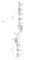
- FIG. 1 is a block diagram showing an example of a schematic configuration of an arithmetic device 100 according to the first embodiment.
- the arithmetic device 100 includes, for example, a synthesis unit 110, a Fourier transform unit 120, and a separation unit 130.
- the arithmetic device 100 includes, as specific hardware, arithmetic means such as a CPU and arithmetic processor, a memory that can be accessed by the arithmetic means and can write and read data, and an interface circuit that is configured to be able to exchange data from the outside. Etc.
- the arithmetic means executes a predetermined software program
- the synthesis unit 110, the Fourier transform unit 120, and the separation unit 130 are functionally realized.
- the first real signal x and the second real signal y are input to the synthesis unit 110 from the outside of the arithmetic device 100.
- the first actual signal x and the second actual signal y are signals of physical quantities such as position, speed, acceleration, pressure, sound pressure, temperature, humidity, dryness, voltage, and current, respectively. Therefore, the first real signal x and the second real signal y are real signals represented only by real numbers.
- the first real signal x and the second real signal y are also discrete signals including the same number of samples (number of samples) N (N is a positive integer).
- the first real signal x and the second real signal y can be generated by sampling (sampling) the number of samples N, for example, at a predetermined sampling frequency.
- Each of the first real signal x and the second real signal y is, for example, data composed of a plurality of data units in which one data unit (a predetermined number of bytes) is assigned to a discrete value corresponding to one sampling. Is stored in the memory as a collection of.
- the combining unit 110 is configured to combine the first real signal x and the second real signal y into a combined complex signal w having the first real signal x as a real part and the second real signal y as an imaginary part. Has been.
- the combining unit 110 outputs the combined complex signal w to the Fourier transform unit 120.
- the synthesis unit 110 reads the first real signal x and the second real signal y stored in the memory, performs a synthesis operation, and writes the result as a synthesized complex signal w in the memory.
- the composite complex signal w is stored in the memory as a collection of data composed of a plurality of data units, for example, one data unit assigned to each discrete value.
- the Fourier transform unit 120 is configured to perform a Fourier transform on the composite complex signal w input from the composite unit 110.
- the Fourier transform unit 120 is configured to perform fast Fourier transform on the composite complex signal w.
- the Fourier transform unit 120 outputs the spectrum W subjected to Fourier transform or fast Fourier transform to the separation unit 130.
- the Fourier transform unit 120 reads the composite complex signal w stored in the memory, executes a fast Fourier calculation, and writes the calculation result as a spectrum W in the memory.
- the separation unit 130 is configured to separate the spectrum W into a first spectrum X obtained by Fourier transform of the first real signal x and a second spectrum Y obtained by Fourier transform of the second real signal y.
- the separation unit 130 outputs the separated first spectrum X and second spectrum Y to the outside of the arithmetic device 100, for example.
- the separation unit 130 reads the spectrum W stored in the memory, performs a separation operation, and writes the spectrum W into the first spectrum X and the second spectrum Y.
- the first spectrum X and the second spectrum Y written in the memory are output to the outside via the interface circuit.
- the Fourier transform is expressed by, for example, the following expression (1) using a function x (t) to be subjected to Fourier transform and a spectrum function X ( ⁇ ) subjected to Fourier transform.
- t is time and ⁇ is angular frequency.
- the function x (t) that is the object of Fourier transform is a real number function
- the first real signal x and the second real signal y that are discrete signals are also real numbers.
- the Fourier-transformed spectral function X ( ⁇ ) has an amplitude and a phase in frequency, and thus becomes a complex number function represented by a complex number.
- the first spectrum X and the second spectrum Y, which are the discrete spectrum, are also complex numbers. is there.
- ⁇ t is the sampling interval (time) of the discrete signal data x k
- the N Fourier coefficients X m are frequency signals after Fourier transform, that is, each frequency component in the spectrum X.
- frequency components exceeding the Nyquist frequency f n are folded in the frequency space.
- fast Fourier transform is known as one of methods for efficiently calculating discrete Fourier transform.
- fast Fourier Transform There are various types of Fast Fourier Transform, but the most common and widely used algorithm based on 2 will be described below.
- N 2 n
- n is a positive integer
- Frequency f m corresponding to the m-th frequency components of the spectrum is represented by the following equation (6).
- N discrete signal data x k is fast Fourier transformed, N frequency components X m of the spectrum X are obtained.
- an index (subscript m) from 0 to N / 2 of the N frequency components X m is physically Has meaning.
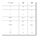
- FIG. 2 is a table showing an example of the relationship between the index m in the frequency component Xm of the spectrum X and the corresponding positive frequency domain index.
- the index m from 1 to (N / 2) -1 is called the positive frequency region
- the index m from (N / 2) +1 to N-1 is called the negative frequency region.
- the frequency component in the negative frequency region corresponds to the frequency component in the positive frequency region.
- a frequency component X (N / 2) +1 with an index m of (N / 2) +1 corresponds to a frequency component X (N / 2) -1 with an index m of (N / 2) ⁇ 1.
- the frequency component X N-1 where m is N-1 corresponds to the frequency component X 1 where the index m is 1.
- the frequency component X m having an index m that is a negative frequency region and having an index m greater than N / 2 is a complex conjugate with the corresponding frequency component Xm of the positive frequency region as a result of folding.
- * represents a complex conjugate
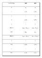
- FIG. 3 is a table showing an example of the relationship between the index m, the real part, and the imaginary part in the frequency component X m of the spectrum X.
- the spectrum X is composed of N frequency components X m having an index m of 0 to N ⁇ 1, and has 2N degrees of freedom.
- the conventional arithmetic unit when performing the fast Fourier transform, the butterfly and the array are rearranged in the same memory space, and the same memory area is used for input and output of the fast Fourier transform. There were many things. For this reason, the conventional arithmetic unit treats the input of the fast Fourier transform as a complex number having 2N degrees of freedom, like the output.
- the input of the fast Fourier transform is a real signal
- the input of the fast Fourier transform is actually N degrees of freedom.
- the conventional arithmetic unit uses only half of the input and output with 2N degrees of freedom. Further, the conventional arithmetic unit performs fast Fourier transform on two real signal inputs to obtain two spectra as outputs.
- the inventor of the present application obtains a complex spectrum by arranging two real signals in a real part and an imaginary part of a complex number and performing Fourier transform, and two real signals are obtained from the real part and the imaginary part of the spectrum. We came up with obtaining each spectrum of the signal.
- the second real signal y is N real discrete signal data y.
- the degree of freedom is N.
- Y m c m + jd m (10)
- the frequency component X 0, which is a direct current component of the first spectrum X is expressed by, for example, the following equation (11) from the above equation (2).
- the frequency component X 0 is a real number and has no imaginary part.
- the frequency component X N / 2 that is the Nyquist frequency component of the first spectrum X is expressed by the following equation (12) from the above equation (2).
- the frequency component X N / 2 is also a real number and has no imaginary part.
- the frequency component in the negative frequency region of the first spectrum X is a complex conjugate of the frequency component in the corresponding positive frequency region.
- the point that the DC component and the Nyquist frequency component are real numbers, and the point that the frequency component in the negative frequency region is a complex conjugate of the corresponding frequency component in the positive frequency region Is the same.
- FIG. 4 is a table showing an example of the relationship between the index m and the real part and the imaginary part in the frequency component X m of the first spectrum X according to the first embodiment
- FIG. 5 shows the second spectrum Y according to the first embodiment.
- surface which shows an example of the relationship between the index m in the frequency component Ym, a real part, and an imaginary part.
- the independent values are as follows: real part a 0 , a 1 , a 2 ,..., A N / 2 , imaginary part b 1 , b 2 , ..., a N / 2-1 N pieces.
- the first real signal x that is the input of the fast Fourier transform has N degrees of freedom
- the first spectrum X that is the output of the fast Fourier transform also has N degrees of freedom.
- independent values are c 0 , c 1 , c 2 ,..., C N / 2
- imaginary parts are d 1 and d 2. ,..., D N / 2-1 .
- the second real signal y that is the input of the fast Fourier transform has N degrees of freedom
- the second spectrum Y that is the output of the fast Fourier transform also has N degrees of freedom.
- FIG. 6 is a table showing an example of the relationship between the index m, the real part, and the imaginary part in the frequency component jY m of the spectrum jY.
- the frequency component jY m of the spectrum jY has the real part shown in FIG. 5 becomes an imaginary part and the imaginary part shown in FIG. It has become.
- the combining unit 110 combines the first real signal x and the second real signal y with the first real signal x as a real part and the second real signal y as an imaginary part.
- the signal w is combined.
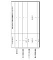
- FIG. 7 is a table showing an example of the relationship between the index k and the real and imaginary parts in the composite complex signal w according to the first embodiment.
- the real discrete signal data x k of the first real signal x is arranged in the real part
- the real discrete signal data y k of the second real signal y is Located in the imaginary part.
- the combining unit 110 combines the first real signal x and the second real signal y into a combined complex signal w having the first real signal x as a real part and the second real signal y as an imaginary part.
- the first real signal x and the second real signal y each having N degrees of freedom are combined into a combined complex signal w having 2N degrees of freedom.
- the Fourier transform unit 120 performs a Fourier transform on the composite complex signal w.
- the Fourier transform unit 120 performs fast Fourier transform on the composite complex signal w.
- the separation unit 130 separates the spectrum W into a first spectrum X obtained by Fourier transforming the first real signal x and a second spectrum Y obtained by Fourier transforming the second real signal y. To do. As a result, it is possible to obtain both the first spectrum X and the second spectrum Y from the spectrum W obtained by performing Fourier transform on the combined complex signal w once.
- FIG. 8 is a table showing an example of the relationship between the index m, the real part, and the imaginary part in the frequency component W m of the spectrum W according to the first embodiment.
- the real part a 0 which is the direct current component of the first spectrum X is obtained from the real part of the direct current component of the spectrum W.
- the real part c 0 which is the direct current component of the second spectrum Y is obtained from the imaginary part of the direct current component of the spectrum W.
- the real part a N / 2 that is the Nyquist frequency component of the first spectrum X is obtained from the real part of the Nyquist frequency component of the spectrum W
- the real part c N / 2 that is the Nyquist frequency component of the second spectrum Y is obtained from the imaginary part of the Nyquist frequency component of the spectrum W.
- the p-th frequency component (p is an integer greater than or equal to 1 and less than N / 2) has a real part a p ⁇ d p , and the frequency in the negative frequency domain corresponding to this frequency component The component has a real part a p + d p .
- the separation unit 130, a real part a p -d p in the positive frequency region of the spectrum W, the real part of the negative frequency region of the spectrum W is based on the a p + d p, p of the first spectrum X
- the real part a p of the th frequency component and the imaginary part d p of the p th frequency component of the second spectrum Y can be separated.
- the real part a p ⁇ d p in the positive frequency domain and the real part in the negative frequency domain add a p + d p and divide by 2 (divide) by the first spectrum.
- the real part a p of the p-th frequency component of X can be obtained.
- a positive real part in the real part a p -d p and negative frequency region is divided by 2 by subtracting the a p + d p in the frequency domain (divided) that is, p of the second spectrum Y
- An imaginary part d p of the th frequency component can be obtained.
- the separation unit 130 performs the p-th of the first spectrum X based on the imaginary part c p + b p in the positive frequency domain of the spectrum W and the imaginary part c p -d p in the negative frequency domain of the spectrum W. Can be separated into an imaginary part b p of the second frequency component Y and a real part c p of the p-th frequency component of the second spectrum Y.
- the first spectrum X is obtained by subtracting and dividing (dividing) the imaginary part c p + b p in the positive frequency domain and the imaginary part c p ⁇ d p in the negative frequency domain by 2.
- the imaginary part b p of the p-th frequency component can be obtained.
- the imaginary part c p + b p in the positive frequency domain and the imaginary part c p ⁇ d p in the negative frequency domain are added and divided by 2 (divided), whereby the p th of the second spectrum Y it is possible to obtain the real part c p of frequency components.
- the separating unit 130 can separate the first spectrum X and the second spectrum Y from the spectrum W by addition and subtraction.
- the separation unit 130 divides (divides) all factors by 2 when a p , b p , c p , and d p are obtained has been described. In some cases, dividing by 2 may be omitted. For example, in the case of the first embodiment described later, since the multiplication is converted into addition by the logarithmization unit, it can be dealt with by subtracting after logarithmization. Further, for example, in the case of the second embodiment described later, even if all frequency components of the spectrum obtained by the Fourier transform are all doubled, it does not affect the peak position of the correlation calculation, so that division by 2 can be omitted. .
- the spectrum W is separated into the first spectrum X and the second spectrum Y, addition / subtraction is performed, but the calculation of the first spectrum X and the second spectrum Y is prevented so as not to cause miscalculation due to missing digits or missing information.
- the first real signal x and the second real signal y are given so that each frequency component has a similar value. If one frequency component of the first spectrum X and the second spectrum Y is an order of magnitude greater than the other frequency component, the number of significant digits may be reduced when the other frequency component is added or subtracted. Because.
- the amount of calculation is considered to be proportional to the number of multiplications (number).
- the synthesizing unit 110 of the present embodiment does not include multiplication because it simply synthesizes the first real signal x and the second real signal y by substituting them into the real part and the imaginary part of the composite complex signal w. Therefore, the synthesis unit 110 can be regarded as having no calculation amount.
- the separation unit 130 of this embodiment can separate the first spectrum X and the second spectrum Y from the spectrum W by addition / subtraction.
- the separation unit 130 can also be regarded as having no calculation amount.
- the Fourier transform unit 120 of the present embodiment calculates using the above-described equation (2).
- equation (2) when the discrete signal data x k is a real number, 2N multiplications are performed for each frequency component. Therefore, when performing the discrete Fourier transform, the Fourier transform unit 120 performs 2N 2 multiplications.
- the Fourier transform unit 120 when the Fourier transform unit 120 performs fast Fourier transform, 2N multiplications are performed in n stages.
- FIG. 9 is a block diagram showing an example of the configuration of the spectrum analyzer 150 including the arithmetic device 100 according to the first embodiment.
- the spectrum analyzer 150 includes, for example, the arithmetic device 100 described above, a logarithmization unit 151, and a logarithmization unit 152.
- the logarithmization units 151 and 152 are configured as specific hardware such as a calculation unit such as a CPU or a calculation processor, a memory that can be accessed by the calculation unit, and that can write and read data, and can exchange data from the outside. Interface circuit etc.
- the logarithmization units 151 and 152 are functionally realized by the calculation means executing a predetermined software program.
- the L channel speech discrete signal and the R channel speech discrete signal as the first actual signal x and the second actual signal y are input to the synthesis unit 110 of the arithmetic device 100.
- the separation unit 130 of the arithmetic device 100 outputs the separated first spectrum X to the logarithmization unit 151 and outputs the separated second spectrum Y to the logarithmization unit 152.
- the logarithmization unit 151 and the logarithmization unit 152 are configured to calculate the logarithm of the input value.
- the logarithmization unit 151 calculates a logarithm for the input first spectrum X, and outputs the logarithmized first spectrum X to the outside.
- the logarithmization unit 152 calculates a logarithm for the input second spectrum Y, and outputs the logarithmized second spectrum Y to the outside.
- the logarithmized first spectrum X is used, for example, as the sound pressure level for each frequency in the L channel sound
- the logarithmized second spectrum Y is, for example, the sound pressure level for each frequency in the R channel sound.
- the logarithmization unit 151 reads the first spectrum X stored in the memory, performs a logarithmic operation, stores the logarithmized first spectrum X in the memory, and stores the first spectrum X via the interface circuit. Is output.
- the logarithmization unit 152 reads the second spectrum Y stored in the memory, performs a logarithmic operation, stores the logarithmized second spectrum Y in the memory, and outputs the second spectrum Y via the interface circuit. To do.
- FIG. 10 is a block diagram illustrating an example of a configuration of a correlation calculation device 160 including the calculation device 100 according to the first embodiment.
- the correlation calculation device 160 includes, for example, the above-described calculation device 100, a complex conjugate derivation unit 161, a multiplier 162, and an inverse Fourier transform unit 163.
- the complex conjugate deriving unit 161, the multiplier 162, and the inverse Fourier transform unit 163 include, as specific hardware, arithmetic means such as a CPU and arithmetic processor, and a memory that can be accessed by the arithmetic means and can write and read data. And an interface circuit configured to exchange data from the outside.
- the arithmetic means executes a predetermined software program
- the complex conjugate derivation unit 161, the multiplier 162, and the inverse Fourier transform unit 163 are functionally realized.
- the separation unit 130 of the arithmetic device 100 outputs the separated first spectrum X to the complex conjugate derivation unit 161 and outputs the separated second spectrum Y to the multiplier 162.
- the complex conjugate derivation unit 161 is configured to derive the complex conjugate of the input value.
- the complex conjugate derivation unit 161 derives a complex conjugate from the input first spectrum X, and outputs the complex conjugate of the first spectrum X to the multiplier 162.
- the complex conjugate derivation unit 161 reads data related to the complex conjugate from the first spectrum X stored in the memory and writes the data in another area of the memory.
- the multiplier 162 is configured to multiply a plurality of input values.
- the multiplier 162 multiplies the complex conjugate of the first spectrum X from the complex conjugate derivation unit 161 and the second spectrum Y from the separation unit 130, and outputs the calculated value to the inverse Fourier transform unit 163.
- the multiplier 162 reads the complex conjugate of the first spectrum X stored in the memory and the second spectrum Y written from the arithmetic device 100, executes the multiplication operation, and writes the operation result in the memory.
- the inverse Fourier transform unit 163 is configured to perform inverse Fourier transform on the input value.
- the inverse Fourier transform unit 163 performs inverse Fourier transform on the value from the multiplier, and outputs the value after the inverse Fourier transform, for example, to the outside.
- the output of the inverse Fourier transform unit 163 can be used as a correlation in the frequency domain (frequency space) between the first real signal x and the second real signal y.
- the inverse Fourier transform unit 163 reads the multiplication result stored in the memory, executes the inverse Fourier transform operation, stores the operation result in the memory, and outputs it to the outside via the interface circuit.
- the arithmetic device 100 can also be applied to, for example, an image processing device (not shown) that performs image processing of a two-dimensional image.
- an image processing apparatus may perform two-dimensional Fourier transform.
- a two-dimensional spectrum is obtained by performing a one-dimensional Fourier transform for each row of the two-dimensional image and then performing a one-dimensional Fourier transform for each column of the two-dimensional image.
- the one-dimensional Fourier transform may be performed for each row of the two-dimensional image after the one-dimensional Fourier transform is performed for each column of the two-dimensional image.
- an image processing apparatus using a conventional arithmetic unit needs to perform 256 one-dimensional Fourier transform for each row and perform 256 one-dimensional Fourier transform for each column. There were a total of 512 Fourier transforms.
- the first real signal x and the second real signal y which are real discrete signals each including the number of samples N (N is a positive integer), are used for the first real signal x.
- a synthesis unit 110 that synthesizes the synthesized complex signal w with the signal x as a real part and the second real signal y as an imaginary part is provided.
- the first real signal x and the second real signal y each having N degrees of freedom are combined into a combined complex signal w having 2N degrees of freedom. Therefore, the calculation efficiency of the Fourier transform can be improved as compared with a conventional arithmetic device that has performed a Fourier transform on a signal having N degrees of freedom.
- the arithmetic device 100 of the present embodiment includes a Fourier transform unit 120 that performs a Fourier transform on the composite complex signal w, and a spectrum W that is an output of the Fourier transform unit 120, and a first spectrum X that is obtained by Fourier transforming the first real signal x.
- a separation unit 130 that separates the second actual signal y into a second spectrum Y obtained by Fourier transform.
- Second Embodiment 11 to 14 are for illustrating a second embodiment of the arithmetic unit according to the present invention.
- the same components as those in the first embodiment are denoted by the same reference numerals, and the description thereof is omitted.
- components similar to those in the first embodiment described above are denoted by similar symbols, and detailed description thereof is omitted.
- constituent parts and operations not shown are the same as those in the first embodiment.
- FIG. 11 is a block diagram showing an example of a schematic configuration of the arithmetic device 200 according to the second embodiment.
- the arithmetic device 200 includes, for example, a synthesis unit 210, an inverse Fourier transform unit 220, and a separation unit 230.
- the first spectrum X and the second spectrum Y are input to the synthesis unit 210 from the outside of the arithmetic device 200.
- the first spectrum X and the second spectrum Y are spectra which are real numbers and become real discrete signals including the number of samples (number of samples) N (N is a positive integer), respectively, when inverse Fourier transform is performed. That is, the output obtained by performing the inverse Fourier transform on the first spectrum X becomes the first real signal x that is a real discrete signal, and the output obtained by performing the inverse Fourier transform on the first spectrum X becomes the second real signal y that is a real discrete signal. Become.
- the synthesizing unit 210 is configured to synthesize the first spectrum X and the second spectrum Y into a synthesized spectrum Z.
- the combining unit 110 outputs the combined composite spectrum Z to the inverse Fourier transform unit 220.
- the inverse Fourier transform unit 220 is configured to perform an inverse Fourier transform on the combined spectrum Z input from the combining unit 210.
- the inverse Fourier transform unit 220 is configured to perform an inverse fast Fourier transform on the combined spectrum Z.
- the inverse Fourier transform unit 220 outputs a signal obtained by inverse Fourier transform or inverse fast Fourier transform, that is, a complex signal z, to the separation unit 230.
- the separator 230 converts the complex signal z output from the separator 230 into a first real signal x obtained by inverse Fourier transform of the first spectrum X and a second real signal y obtained by inverse Fourier transform of the second spectrum Y. Configured to separate.
- the separation unit 230 outputs the separated first real signal x and second real signal y to the outside of the arithmetic device 200, for example.
- the inverse fast Fourier transform can be performed by almost the same operation as the above-described fast Fourier transform using butterfly computation and array rearrangement (bit reverse).
- the real signal x including the real discrete signal data x k obtained by the equation (17) has a value that is N times larger than the original signal, all the real discrete signal data x k are increased by the same amount. Often not a problem.
- the second spectrum Y obtained by inverse fast Fourier transform to obtain a second real signal y including N real discrete signal data y k (k 0, 1, 2,..., N ⁇ 1)
- the component Y m can be represented by the above formula (10).
- the direct current component and the Nyquist frequency component are real numbers, and the frequency component in the negative frequency region is a complex conjugate of the frequency component in the positive frequency region to which the frequency component corresponds.
- the point is the same as in the case of the fast Fourier transform described above. Therefore, the first spectrum X and the second spectrum Y have N degrees of freedom.
- the combining unit 210 combines the first spectrum X and the second spectrum Y with the combined spectrum Z. Specifically, the combining unit 210, for example, multiplied by the imaginary unit into frequency components Y m of the second spectrum Y those (multiplied) is added to the frequency components X m of the first spectrum X, the synthetic spectrum Z Is synthesized.
- FIG. 12 is a table showing an example of the relationship between the index m, the real part, and the imaginary part in the frequency component Z m of the composite spectrum Z according to the second embodiment.
- the q-th frequency component (q is an integer greater than or equal to 1 and less than N / 2) has a real part a q -d q , and a negative component corresponding to this frequency component.
- the real component of the frequency component in the frequency domain is a q + d q .
- the imaginary part of the q-th frequency component in the positive frequency region is c q + b q
- the frequency component in the negative frequency region corresponding to this frequency component is c q ⁇ d q .
- the synthesis unit 210 synthesizes the first spectrum X and the second spectrum Y into the synthesis spectrum X, so that the first spectrum X and the second spectrum Y each having N degrees of freedom are synthesized with 2N degrees of freedom. Synthesized into the spectrum Z.
- the inverse Fourier transform unit 220 performs inverse Fourier transform on the composite spectrum Z.
- the inverse Fourier transform unit 220 performs inverse fast Fourier transform on the combined spectrum Z.
- the separation unit 230 performs a first real signal x obtained by performing an inverse Fourier transform on the first spectrum X and a second actual signal obtained by performing an inverse Fourier transform on the second spectrum X on the complex signal z. Separated into y.
- FIG. 13 is a table showing an example of the relationship between the index k, the real part, and the imaginary part in the complex signal z according to the second embodiment.
- the separation unit 230 separates the first real signal x obtained by performing the inverse Fourier transform on the first spectrum X from the real part of the complex signal z, and the second obtained by performing the inverse Fourier transform on the second spectrum Y from the imaginary part of the complex signal z.
- FIG. 14 is a block diagram illustrating an example of a configuration of a Hilbert correlation calculation device 250 including the calculation device 100 according to the first embodiment and the calculation device 200 according to the second embodiment.
- the Hilbert correlation calculation device 250 includes, for example, the calculation device 100 according to the first embodiment, a complex conjugate derivation unit 251, a multiplier 252, a Hilbert transform unit 253, and the calculation device 200 described above.
- the arithmetic device 100, complex conjugate derivation unit 251, and multiplier 252 of the Hilbert correlation arithmetic device 250 are the same as the arithmetic device 100, complex conjugate derivation unit 161, and multiplier 162 of the correlation arithmetic device 160 shown in FIG. Therefore, the description is omitted.
- the Hilbert transform unit 253 is configured to perform a Hilbert transform on the input value.
- the Hilbert transform unit 253 performs Hilbert transform on the value from the multiplier 252 in the frequency domain, and outputs the value after the Hilbert transform to the synthesis unit 210 of the arithmetic device 200.
- the value from the multiplier 252 as the first spectrum X and the value from the Hilbert transform unit 253 as the second spectrum Y are input to the synthesis unit 210 of the arithmetic device 200.
- the separation unit 230 of the arithmetic device 200 outputs the separated first real signal x and second real signal y to the phase relationship deriving unit 254.
- the phase relationship deriving unit 254 is configured to derive the phase relationship of a plurality of input values.
- the phase relationship deriving unit 254 derives the phase relationship between the first real signal x and the second real signal y output from the separation unit 230 of the arithmetic device 200, and outputs the derived phase relationship to the linear approximation unit 255.
- the linear approximation unit 255 is configured to interpolate the phase relationship that is the output of the phase relationship deriving unit 254 by linear approximation.
- the linear approximation unit 255 outputs the complemented phase relationship to the outside, for example.
- As the output value of the linear approximation unit 255 for example, a point where the phase relationship becomes 0 can be used as the correlation peak position.
- the first spectrum X and the second spectrum Y which are real discrete signals each including the number of samples N (N is a positive integer) by inverse Fourier transform
- a combining unit 210 for combining with Z is provided.
- the first spectrum X and the second spectrum Y each having N degrees of freedom are combined into a combined spectrum Z having 2N degrees of freedom. Therefore, the calculation efficiency of the inverse Fourier transform can be improved as compared with the conventional calculation device that performs the inverse Fourier transform on the spectrum having N degrees of freedom.
- the inverse Fourier transform unit 220 that performs inverse Fourier transform on the composite spectrum Z, and the first signal obtained by performing inverse Fourier transform on the first spectrum X from the real part of the complex signal z with respect to the complex signal z that is the output of the inverse Fourier transform unit 220.
- a separation unit 230 that separates the real signal x and separates the second real signal y obtained by performing inverse Fourier transform on the second spectrum Y from the imaginary part of the complex signal z. This makes it possible to obtain both the first real signal x and the second real signal y from the complex signal z obtained by performing inverse Fourier transform on the combined spectrum Z once. Therefore, the number of computations (the number of computations) of the inverse Fourier transform can be reduced as compared with a conventional computation device that has inverse Fourier transformed each of the two spectra.
Landscapes
- Engineering & Computer Science (AREA)
- Physics & Mathematics (AREA)
- Mathematical Physics (AREA)
- General Physics & Mathematics (AREA)
- Pure & Applied Mathematics (AREA)
- Mathematical Optimization (AREA)
- Mathematical Analysis (AREA)
- Computational Mathematics (AREA)
- Data Mining & Analysis (AREA)
- Theoretical Computer Science (AREA)
- Algebra (AREA)
- Databases & Information Systems (AREA)
- Software Systems (AREA)
- General Engineering & Computer Science (AREA)
- Complex Calculations (AREA)
Abstract
フーリエ変換および逆フーリエ変換の少なくとも一方をより効率的に行うことのできる演算装置を提供する。演算装置100は、それぞれ標本数N(Nは正の整数)を含む実数離散信号である第1実信号xおよび第2実信号yに対し、第1実信号xを実部とし、第2実信号yを虚部とする合成複素信号wに合成する合成部110と、合成複素信号wをフーリエ変換するフーリエ変換部120と、フーリエ変換部の出力であるスペクトルWを、第1実信号xをフーリエ変換した第1スペクトルXと、第2実信号yをフーリエ変換した第2スペクトルYとに分離する分離部130と、を備える。
Description
本発明に係るいくつかの態様は、フーリエ変換および逆フーリエ変換のうちの少なくとも一方を行う演算装置に関する。
従来、この種の演算装置として、第1および第2の信号をフーリエ変換した値を、ヒルベルト変換した後に逆フーリエ演算を行うものが知られている(例えば、特許文献1参照)。この演算装置では、周波数領域においてヒルベルト変換することにより、第1および第2の信号の時間差を、比較的少ない演算量で求めることができる。
従来の演算装置では、一般に、2つの信号に対してフーリエ変換を行う場合、2つの信号のそれぞれをフーリエ変換していた。同様に、2つのスペクトルに対して逆フーリエ変換を行う場合、2つのスペクトルのそれぞれを逆フーリエ変換していた。
近年、演算装置において、リソースの削減、演算時間の短縮、消費電力量の低減などの要求がますます高まっており、演算負荷の大きいフーリエ変換および逆フーリエ変換の効率化が求められている。
本発明のいくつかの態様は上記した問題に鑑みてなされたものであり、フーリエ変換および逆フーリエ変換の少なくとも一方をより効率的に行うことのできる演算装置を提供することを目的の1つとする。
本発明の一態様における演算装置は、それぞれ標本数N(Nは正の整数)を含む実数離散信号である第1の実信号および第2の実信号に対し、第1の実信号を実部とし、第2の実信号を虚部とする合成複素信号に合成する合成部と、合成複素信号をフーリエ変換するフーリエ変換部と、フーリエ変換部の出力であるスペクトルを、第1の実信号をフーリエ変換した第1のスペクトルと、第2の実信号をフーリエ変換した第2のスペクトルとに分離する分離部と、を備える。
上記演算装置において、第1の実信号および第2の実信号は、所定のサンプリング周波数で2のべき乗の標本数Nをそれぞれサンプリングしたものであり、分離部は、スペクトルの正の周波数領域における実部とスペクトルの負の周波数領域における実部とに基づいて、第1のスペクトルの実部と、第2のスペクトルの虚部とに分離し、スペクトルの正の周波数領域における虚部とスペクトルの負の周波数領域における虚部とに基づいて、第1のスペクトルの虚部と、第2のスペクトルの実部とに分離してもよい。
上記演算装置において、フーリエ変換部は、合成複素信号を高速フーリエ変換してもよい。
また、本発明の一態様における演算装置は、逆フーリエ変換するとそれぞれ標本数N(Nは正の整数)を含む実数離散信号になる第1のスペクトルおよび第2のスペクトルを、合成スペクトルに合成する合成部と、合成スペクトルを逆フーリエ変換する逆フーリエ変換部と、逆フーリエ変換部の出力である複素信号に対し、複素信号の実部から第1のスペクトルを逆フーリエ変換した第1の実信号を分離し、複素信号の虚部から前記第2のスペクトルを逆フーリエ変換した第2の実信号を分離する分離部と、を備える。
上記演算装置において、第1の実信号および第2の実信号は、所定のサンプリング周波数で2のべき乗の標本数Nをそれぞれサンプリングしたものであり、合成部は、第2のスペクトルの周波数成分に虚数単位を乗じたものを、第1のスペクトルの周波数成分に加算し、合成スペクトルを合成してもよい。
上記演算装置において、逆フーリエ変換部は、合成スペクトルを逆高速フーリエ変換してもよい。
本発明の一態様における演算装置によれば、それぞれ標本数N(Nは正の整数)を含む実数離散信号である第1の実信号および第2の実信号に対し、第1の実信号を実部とし、第2の実信号を虚部とする合成複素信号に合成する合成部を備える。これにより、それぞれ自由度Nを有する第1の実信号および第2の実信号が、自由度2Nの合成複素信号に合成される。したがって、自由度Nの信号をフーリエ変換していた従来の演算装置と比較して、フーリエ変換の演算効率を向上させることができる。また、本発明の一態様における演算装置は、合成複素信号をフーリエ変換するフーリエ変換部と、フーリエ変換部の出力であるスペクトルを、第1の実信号をフーリエ変換した第1のスペクトルと、第2の実信号をフーリエ変換した第2のスペクトルとに分離する分離部と、を備える。これにより、合成複素信号を1回フーリエ変換したスペクトルから、第1のスペクトルと第2のスペクトルの両方を得ることが可能になる。したがって、2つの実信号をそれぞれフーリエ変換していた従来の演算装置と比較して、フーリエ変換の演算回数(演算数)を削減することができる。
また、本発明の一態様における演算装置によれば、逆フーリエ変換するとそれぞれ標本数N(Nは正の整数)を含む実数離散信号になる第1のスペクトルおよび第2のスペクトルを、合成スペクトルに合成する合成部を備える。これにより、それぞれ自由度Nを有する第1のスペクトルおよび第2のスペクトルが、自由度2Nの合成スペクトルに合成される。したがって、自由度Nのスペクトルを逆フーリエ変換していた従来の演算装置と比較して、逆フーリエ変換の演算効率を向上させることができる。また、合成スペクトルを逆フーリエ変換する逆フーリエ変換部と、逆フーリエ変換部の出力である複素信号に対し、複素信号の実部から第1のスペクトルを逆フーリエ変換した第1の実信号を分離し、複素信号の虚部から第2のスペクトルを逆フーリエ変換した第2実信号を分離する分離部と、を備える。これにより、合成スペクトルを1回逆フーリエ変換した複素信号から、第1の実信号と第2の実信号の両方を得ることが可能になる。したがって、2つのスペクトルをそれぞれ逆フーリエ変換していた従来の演算装置と比較して、逆フーリエ変換の演算回数(演算数)を削減することができる。
以下に本発明の実施形態を説明する。以下の図面の記載において、同一または類似の部分には同一または類似の符号で表している。但し、図面は模式的なものである。したがって、具体的な寸法などは以下の説明を照らし合わせて判断するべきものである。また、図面相互間においても互いの寸法の関係や比率が異なる部分が含まれていることは勿論である。さらに、本発明の技術的範囲は、当該実施形態に限定して解するべきではない。なお、以下の説明において、図面の上側を「上」、下側を「下」、左側を「左」、右側を「右」という。
<第1実施形態>
図1乃至図10は、本発明に係る演算装置の第1実施形態を示すためのものである。図1は、第1実施形態に従う演算装置100の概略構成の一例を示すブロック図である。図1に示すように、演算装置100は、例えば、合成部110と、フーリエ変換部120と、分離部130と、を備える。演算装置100は、具体的なハードウェアとしては、CPUや演算プロセッサ等の演算手段、演算手段がアクセス可能でデータの書き込みおよび読み出しが可能なメモリ、外部からデータの授受可能に構成されたインターフェース回路等を備える。演算手段が、所定のソフトウェアプログラムを実行することにより、合成部110、フーリエ変換部120、および分離部130が機能的に実現される。
図1乃至図10は、本発明に係る演算装置の第1実施形態を示すためのものである。図1は、第1実施形態に従う演算装置100の概略構成の一例を示すブロック図である。図1に示すように、演算装置100は、例えば、合成部110と、フーリエ変換部120と、分離部130と、を備える。演算装置100は、具体的なハードウェアとしては、CPUや演算プロセッサ等の演算手段、演算手段がアクセス可能でデータの書き込みおよび読み出しが可能なメモリ、外部からデータの授受可能に構成されたインターフェース回路等を備える。演算手段が、所定のソフトウェアプログラムを実行することにより、合成部110、フーリエ変換部120、および分離部130が機能的に実現される。
合成部110には、例えば演算装置100の外部から、第1実信号xと第2実信号yとが入力される。第1実信号xおよび第2実信号yは、それぞれ、例えば位置、速度、加速度、圧力、音圧、温度、湿度、乾き度、電圧、電流などの物理量の信号である。そのため、第1実信号xおよび第2実信号yは、実数のみで表される実信号である。また、第1実信号xおよび第2実信号yは、同数の標本数(サンプル数)N(Nは正の整数)を含む離散信号でもある。第1実信号xおよび第2実信号yは、物理量の信号を、例えば所定のサンプリング周波数で標本数Nをそれぞれサンプリング(標本化)して生成することができる。第1実信号xおよび第2実信号yの各々は、例えば、一つのサンプリングに対応する離散値について一つのデータ単位(所定数のバイト)が割り当てられた、複数のデータ単位で構成されるデータの集合体としてメモリに記憶される。
合成部110は、第1実信号xおよび第2実信号yに対し、第1実信号xを実部とし、第2実信号yを虚部とする合成複素信号wに合成するように、構成されている。合成部110は、合成複素信号wをフーリエ変換部120に出力する。例えば、合成部110は、メモリに格納された第1実信号xと第2実信号yとを読み出し、合成演算を実施して合成複素信号wとしてメモリに書き込む。合成複素信号wは、例えば、離散値毎に一つのデータ単位が割り当てられた、複数のデータ単位で構成されるデータの集合体としてメモリに記憶される。
フーリエ変換部120は、合成部110から入力された合成複素信号wをフーリエ変換するように、構成されている。好ましくは、フーリエ変換部120は、合成複素信号wを高速フーリエ変換するように、構成されている。フーリエ変換部120は、フーリエ変換または高速フーリエ変換したスペクトルWを、分離部130に出力する。例えば、フーリエ変換部120は、メモリに格納された合成複素信号wを読み出して高速フーリエ演算を実行し、演算結果をスペクトルWとしてメモリに書き込む。
分離部130は、スペクトルWを、第1実信号xをフーリエ変換した第1スペクトルXと、第2実信号yをフーリエ変換した第2スペクトルYとに分離するように、構成されている。分離部130は、分離した第1スペクトルXおよび第2スペクトルYを、例えば演算装置100の外部に出力する。例えば、分離部130は、メモリに格納されたスペクトルWを読み出して分離演算を実行し、第1スペクトルXと第2スペクトルYとに分けてメモリに書き込む。またメモリに書き込んだ第1スペクトルXおよび第2スペクトルYをインターフェース回路を介して外部に出力する。
一般に、フーリエ変換は、フーリエ変換の対象となる関数x(t)と、フーリエ変換されたスペクトル関数X(ω)とを用いて、例えば以下の式(1)のように表される。

式(1)では、独立変数が時間tの関数x(t)を独立変数が角周波数ωのスペクトル関数X(ω)に変換する例を示したが、これに限定されない。フーリエ変換は、例えば、独立変数が位置の関数を、独立変数が空間周波数のスペクトル関数に変換する場合にも適用することが可能である。但し、説明の簡略化のため、以下において、独立変数が時間tの関数を、独立変数が周波数fの関数に変換する場合について説明する。
式(1)において、フーリエ変換の対象である関数x(t)が実数関数である場合、その離散信号である第1実信号xおよび第2実信号yも実数である。一方、フーリエ変換されたスペクトル関数X(ω)は、周波数における振幅および位相を有するので、複素数で表される複素数関数になり、その離散スペクトルである第1スペクトルXおよび第2スペクトルYも複素数である。
式(1)では、被積分関数である関数x(t)を、独立変数の時間tに対して-∞から∞まで積分する必要があること、および、関数x(t)が連続関数である必要があることから、式(1)を用いてフーリエ変換を行うことは現実的ではない。
そこで、一般には、連続関数に対し、必要な情報を得るために十分に長い時間について、標本数Nの離散信号データxk(N個のうちのk番目の離散信号データを示す)(k=0、1、2、…、N-1)をサンプリング(標本化)した信号を用いる。このような離散信号データxkを用いてフーリエ変換するとき、特に離散フーリエ変換と呼ばれている。この場合、フーリエ係数Xm(N個のうちのm番目のフーリエ係数を示す)(m=0、1、2、…、N-1)は、以下の式(2)のように表される。

サンプリングの際のサンプリング周波数fsは、離散信号データxkのサンプリング間隔Δtを用いて以下の式(3)のように表される。
fs=1/Δt …(3)
fs=1/Δt …(3)
また、ナイキスト周波数fnは、標本化定理から以下の式(4)のように表される。
fn=fs/2=1/2Δt …(4)
fn=fs/2=1/2Δt …(4)
N個のフーリエ係数Xmは、フーリエ変換後の周波数の信号、つまり、スペクトルXにおける各周波数成分である。スペクトルXの各周波数成分のうち、ナイキスト周波数fnを超える周波数成分は、周波数空間上で折り返されることが知られている。
また、離散フーリエ変換を効率的に演算する手法の一つとして、高速フーリエ変換が知られている。高速フーリエ変換は、様々な種類が存在するが、以下において、最も一般的であり、広く用いられている、2を基底とするアルゴリズムについて説明する。
2を基底とするアルゴリズムでは、標本数Nとして2のべき乗を用いる(N=2n)(nは正の整数)。
高速フーリエ変換することで、離散信号の標本数Nと同数の周波数成分で構成されるスペクトルを得ることができる。
スペクトルの周波数fの間隔Δfは、以下の式(5)のように表される。
Δf=Δω/2π=1/NΔt=fs/N …(5)
Δf=Δω/2π=1/NΔt=fs/N …(5)
スペクトルのm番目の周波数成分に対応する周波数fmは、以下の式(6)のように表される。
fm=mΔf=m/NΔt=fsm/N …(6)
fm=mΔf=m/NΔt=fsm/N …(6)
標本数Nの半分のときの周波数fN/2がナイキスト周波数fnであり、以下の式(7)のように表される。
fn=fN/2=fs/2 …(7)
fn=fN/2=fs/2 …(7)
N個の離散信号データxkを高速フーリエ変換すると、スペクトルXのN個の周波数成分Xmが得られる。上記したように、ナイキスト周波数fnを超える周波数成分は、周波数空間上で折り返されるので、N個の周波数成分Xmのうち、インデックス(添字)mが0からN/2までが、物理的に意味を有する。
図2は、スペクトルXの周波数成分Xmにおけるインデックスmと対応する正の周波数領域のインデックスとの関係の一例を示す表である。図2に示すように、N個の周波数成分Xmのうち、インデックスm=N/2がナイキスト周波数成分であり、インデックスm=0が直流(DC)成分である。また、インデックスmが1から(N/2)-1までは、正の周波数領域と呼ばれ、インデックスmが(N/2)+1からN-1までは、負の周波数領域と呼ばれている。負の周波数領域の周波数成分は、正の周波数領域の周波数成分に対応している。例えば、インデックスmが(N/2)+1の周波数成分X(N/2)+1は、インデックスmが(N/2)-1の周波数成分X(N/2)-1に対応し、インデックスmがN-1の周波数成分XN-1は、インデックスmが1の周波数成分X1に対応している。
また、負の周波数領域であるインデックスmがN/2より大きい周波数成分Xmは、折り返された結果、対応する正の周波数領域の周波数成分Xmに対して複素共役になっている。
すなわち、インデックスmがN/2より大きい場合、スペクトルXの周波数成分Xmは、インデックス(添字)m’(m’=N-m)を用いて、上記した式(2)から以下の式(8)のように表される。

高速フーリエ変換は、N個(=2n)の複素数データに対し、N回のバタフライ演算をnステージ繰り返し、配列の並べ替え(ビットリーバス)を行うことで、演算することができる。
複素数データの高速フーリエ変換の結果、得られるスペクトルXの周波数成分Xmは、実部amと虚部bmと用いて、以下の式(9)のように表される。
Xm=am+jbm …(9)
Xm=am+jbm …(9)
図3は、スペクトルXの周波数成分Xmにおけるインデックスmと実部および虚部との関係の一例を示す表である。図3に示すように、スペクトルXは、インデックスmが0からN-1のN個の周波数成分Xmで構成されており、2Nの自由度を有している。
ここで、従来の演算装置では、高速フーリエ変換する際に、バタフライと配列の並べ替えを同一のメモリ空間に対して行っており、高速フーリエ変換の入力および出力のために同じメモリ領域を使用することが多かった。このため、従来の演算装置は、高速フーリエ変換の入力を、出力と同様に、2Nの自由度を有する複素数として扱っていた。
しかしながら、高速フーリエ変換の入力が実信号である場合、複素数の実部しか使用していないので、高速フーリエ変換の入力は、実際にはNの自由度である。また、上記したように、スペクトルXの負の周波数領域は、正の周波数領域と複素共役になっているので、高速フーリエ変換の出力も、実際にはNの自由度である。このように、従来の演算装置は、自由度2Nの入力および出力に対し、その半分しか使用していなかった。さらに、従来の演算装置は、2つの実信号の入力に対し、それぞれ高速フーリエ変換し、出力として2つのスペクトルを得ていた。
これに対し、本願発明者は、2つの実信号を複素数の実部と虚部に配置してフーリエ変換を行うことで複素数のスペクトルを得て、このスペクトルの実部と虚部から2つの実信号のそれぞれのスペクトルを得ることに想到した。
一例として、第1実信号xがN個の実数離散信号データxk(k=0、1、2、…、N-1)を含み、第2実信号yがN個の実数離散信号データyk(k=0、1、2、…、N-1)を含む場合を考える。第1実信号xおよび第2実信号yは、実部のみを有するから、その自由度はNである。
第1実信号xを高速フーリエ変換して得られる第1スペクトルXは、周波数成分Xm(m=0、1、2、…、N-1)を、上記した式(9)で表すことができる。
一方、第2実信号yを高速フーリエ変換して得られる第2スペクトルYは、周波数成分Ym(m=0、1、2、…、N-1)が、実部cmと虚部dmと用いて以下の式(10)のように表される。
Ym=cm+jdm …(10)
Ym=cm+jdm …(10)
ここで、第1スペクトルXの直流成分である周波数成分X0は、例えば上記した式(2)から、以下の式(11)のように表される。

実数離散信号データxkは実数なので、式(11)から明らかなように、周波数成分X0は実数であり、虚部を有さない。
また、第1スペクトルXのナイキスト周波数成分である周波数成分XN/2は、上記した式(2)から以下の式(12)のように表される。


よって、周波数成分XN/2も実数であり、虚部を有さない。
さらに、上記したように、第1スペクトルXの負の周波数領域における周波数成分は、対応する正の周波数領域の周波数成分の複素共役になっている。
第1スペクトルXにおいて、直流成分およびナイキスト周波数成分が実数である点、ならびに、負の周波数領域における周波数成分が対応する正の周波数領域の周波数成分の複素共役である点は、第2スペクトルYにおいても同様である。
図4は第1実施形態に従う第1スペクトルXの周波数成分Xmにおけるインデックスmと実部および虚部との関係の一例を示す表であり、図5は第1実施形態に従う第2スペクトルYの周波数成分Ymにおけるインデックスmと実部および虚部との関係の一例を示す表である。図4に示すように、第1スペクトルXの周波数成分Xmにおいて、独立した値は、実部がa0、a1、a2、…、aN/2、虚部がb1、b2、…、aN/2-1のN個である。このように、高速フーリエ変換の入力である第1実信号xがNの自由度を有し、高速フーリエ変換の出力である第1スペクトルXも、Nの自由度を有している。図5に示すように、第2スペクトルYの周波数成分Ymにおいて、独立した値は、実部がc0、c1、c2、…、cN/2、虚部がd1、d2、…、dN/2-1のN個である。このように、高速フーリエ変換の入力である第2実信号yがNの自由度を有し、高速フーリエ変換の出力である第2スペクトルYも、Nの自由度を有している。
ここで、実数である第2実信号yを複素数信号の虚部に配置して高速フーリエ変換する場合を考えてみると、そのようなスペクトルjYの周波数成分jYmは、上記した式(2)および式(10)から、以下の式(14)のように表される。

図6は、スペクトルjYの周波数成分jYmにおけるインデックスmと実部および虚部との関係の一例を示す表である。図6に示すように、スペクトルjYの周波数成分jYmは、各インデックスmにおいて、図5に示す実部が、虚部になり、図5に示す虚部が、符号が反転して実部になっている。
本実施形態の演算装置100では、合成部110が、第1実信号xおよび第2実信号yに対し、第1実信号xを実部とし、第2実信号yを虚部とする合成複素信号wに合成する。合成複素信号wは、N個の実数離散信号データwk(k=0、1、2、…、N-1)を含んでいる。
図7は、第1実施形態に従う合成複素信号wにおけるインデックスkと実部および虚部との関係の一例を示す表である。図7に示すように、合成複素信号wは、各インデックスkにおいて、第1実信号xの実数離散信号データxkが実部に配置され、第2実信号yの実数離散信号データykが虚部に配置されている。このように、合成部110が、第1実信号xおよび第2実信号yに対し、第1実信号xを実部とし、第2実信号yを虚部とする合成複素信号wに合成することにより、それぞれ自由度Nを有する第1実信号xおよび第2実信号yが、自由度2Nの合成複素信号wに合成される。
本実施形態の演算装置100では、フーリエ変換部120が、この合成複素信号wをフーリエ変換する。好ましくは、フーリエ変換部120は、合成複素信号wを高速フーリエ変換する。
フーリエ変換部120の出力であるスペクトルWは、上記した式(2)、式(9)、および式(14)から、周波数成分Wm(m=0、1、2、…、N-1)が、以下の式(15)のように表される。

本実施形態の演算装置100では、分離部130が、このスペクトルWを、第1実信号xをフーリエ変換した第1スペクトルXと、第2実信号yをフーリエ変換した第2スペクトルYとに分離する。これにより、合成複素信号wを1回フーリエ変換したスペクトルWから、第1スペクトルXと第2スペクトルYの両方を得ることが可能になる。
図8は、第1実施形態に従うスペクトルWの周波数成分Wmにおけるインデックスmと実部および虚部との関係の一例を示す表である。図8に示すように、第1スペクトルXの直流成分である実部a0は、スペクトルWの直流成分の実部から得られる。また、第2スペクトルYの直流成分である実部c0は、スペクトルWの直流成分の虚部から得られる。同様に、第1スペクトルXのナイキスト周波数成分である実部aN/2は、スペクトルWのナイキスト周波数成分の実部から得られ、第2スペクトルYのナイキスト周波数成分である実部cN/2は、スペクトルWのナイキスト周波数成分の虚部から得られる。
また、正の周波数領域において、p番目(pは1以上N/2未満の整数)の周波数成分は、実部がap-dpであり、この周波数成分に対応する負の周波数領域における周波数成分は、実部がap+dpである。よって、分離部130は、スペクトルWの正の周波数領域における実部ap-dpと、スペクトルWの負の周波数領域における実部がap+dpとに基づいて、第1スペクトルXのp番目の周波数成分の実部apと、第2スペクトルYのp番目の周波数成分の虚部dpとに分離することが可能である。具体的には、例えば、正の周波数領域における実部ap-dpと負の周波数領域における実部がap+dpとを加算して2で除する(割る)ことで、第1スペクトルXのp番目の周波数成分の実部apを得ることができる。また、例えば、正の周波数領域における実部ap-dpと負の周波数領域における実部がap+dpとを減算して2で除する(割る)ことで、第2スペクトルYのp番目の周波数成分の虚部dpを得ることができる。
さらに、正の周波数領域におけるp番目の周波数成分は、虚部がcp+bpであり、この周波数成分に対応する負の周波数領域における周波数成分は、虚部がcp-dpである。よって、分離部130は、スペクトルWの正の周波数領域における虚部cp+bpと、スペクトルWの負の周波数領域における虚部cp-dpとに基づいて、第1スペクトルXのp番目の周波数成分の虚部bpと、第2スペクトルYのp番目の周波数成分の実部cpとに分離することが可能である。具体的には、例えば、正の周波数領域における虚部cp+bpと負の周波数領域における虚部cp-dpとを減算して2で除する(割る)ことで、第1スペクトルXのp番目の周波数成分の虚部bpを得ることができる。また、例えば、正の周波数領域における虚部cp+bpと負の周波数領域における虚部cp-dpとを加算して2で除する(割る)ことで、第2スペクトルYのp番目の周波数成分の実部cpを得ることができる。このように、分離部130は、加減算によってスペクトルWから第1スペクトルXおよび第2スペクトルYを分離することが可能になる。
以上の説明では、分離部130が、ap、bp、cp、dpを求める際にすべての因子に対して2で除して(割って)いる例を示したが、これに限定されず、2で割ることを省略できる場合がある。例えば後述の第1実施例の場合、対数化部により乗算が加算に変換されるため、対数化後に減算することで対応することができる。また、例えば後述の第2実施例の場合、フーリエ変換により得られたスペクトルの各周波数成分がすべて2倍となっていても相関演算のピーク位置には影響しないため、2で割ることを省略できる。
なお、スペクトルWを第1スペクトルXと第2スペクトルYとに分離するときに、加減算を行うが、桁落ち又は情報落ちによる計算誤算が生じないように、第1スペクトルXと第2スペクトルYの各周波数成分が似通った値となるような第1実信号xと第2実信号yとが与えられることが好ましい。第1スペクトルXおよび第2スペクトルYの一方の周波数成分が他方の周波数成分と比較して桁違いに大きい値である場合、他方の周波数成分が加減算の際に有効桁数が小さくなるおそれがあるからである。
一般に、演算量(計算量)は乗算の回数(数)に比例すると考えられる。本実施形態の合成部110は、2つの第1実信号xおよび第2実信号yを合成複素信号wの実部と虚部とに代入して合成するだけなので、乗算は含まない。よって、合成部110は、演算量がないものとみなすことができる。
また、上記したように、本実施形態の分離部130は、加減算によってスペクトルWから第1スペクトルXおよび第2スペクトルYを分離することが可能である。加減算後に2で除する(割る)場合、シフト演算または指数部のデクリメントで行うことができるため、演算量に含まれない。よって、分離部130も、演算量がないものとみなすことができる。
本実施形態のフーリエ変換部120は、例えば離散フーリエ変換を行う場合、上記した式(2)を用いて計算する。式(2)では、離散信号データxkが実数である場合、各周波数成分に対して2N回の乗算を行うことになる。よって、離散フーリエ変換を行う場合、フーリエ変換部120は2N2回の乗算を行っている。
一方、フーリエ変換部120が高速フーリエ変換を行う場合、2N回の乗算をnステージ行っている。高速フーリエ変換は、配列の並べ替え(ビットリバース)を行っているが、配列の並べ替えは乗算を含まない。よって、高速フーリエ変換を行う場合、フーリエ変換部120は2Nn(=2Nlog2N)回の乗算を行っている。
高速フーリエ変換の演算量は、離散フーリエ変換の演算量と比較すると、(2Nlog2N)/2N2=log2N/N倍である。例えば、実数離散信号データxkおよび実数離散信号データykの標本数Nが1024(=210)である場合、高速フーリエ変換の演算量は、離散フーリエ変換の演算量のおよそ1/100になる。このように、フーリエ変換部120が高速フーリエ変換することにより、フーリエ変換の演算量を大幅に低減することが可能になる。
次に、本実施形態の演算装置100を適用した実施例について説明する。
(第1実施例)
図9は、第1実施形態に従う演算装置100を備えるスペクトラムアナライザ150の構成の一例を示すブロック図である。図9に示すように、スペクトラムアナライザ150は、例えば、上記した演算装置100と、対数化部151と、対数化部152と、を備える。対数化部151および152は、具体的なハードウェアとしては、CPUや演算プロセッサ等の演算手段、演算手段がアクセス可能でデータの書き込みおよび読み出しが可能なメモリ、外部からデータの授受可能に構成されたインターフェース回路等を備える。演算手段が、所定のソフトウェアプログラム
を実行することにより、対数化部151および152が機能的に実現される。
図9は、第1実施形態に従う演算装置100を備えるスペクトラムアナライザ150の構成の一例を示すブロック図である。図9に示すように、スペクトラムアナライザ150は、例えば、上記した演算装置100と、対数化部151と、対数化部152と、を備える。対数化部151および152は、具体的なハードウェアとしては、CPUや演算プロセッサ等の演算手段、演算手段がアクセス可能でデータの書き込みおよび読み出しが可能なメモリ、外部からデータの授受可能に構成されたインターフェース回路等を備える。演算手段が、所定のソフトウェアプログラム
を実行することにより、対数化部151および152が機能的に実現される。
演算装置100の合成部110には、第1実信号xとしてLチャネルの音声離散信号と、第2実信号yとしてRチャネルの音声離散信号とが入力される。
演算装置100の分離部130は、分離した第1スペクトルXを対数化部151に出力するとともに、分離した第2スペクトルYを対数化部152に出力する。
対数化部151および対数化部152は、入力値の対数を算出するように、構成されている。対数化部151は、入力された第1スペクトルXに対して対数を計算し、対数化された第1スペクトルXを外部に出力する。同様に、対数化部152は、入力された第2スペクトルYに対して対数を計算し、対数化された第2スペクトルYを外部に出力する。対数化された第1スペクトルXは、例えば、Lチャネルの音声における周波数毎の音圧レベルとして使用し、対数化された第2スペクトルYは、例えば、Rチャネルの音声における周波数毎の音圧レベルとして使用することが可能である。例えば、対数化部151は、メモリに格納された第1スペクトルXを読み出して対数演算を実行し、対数化された第1スペクトルXをメモリに格納するとともに、インターフェース回路を介して第1スペクトルXを出力する。対数化部152は、メモリに格納された第2スペクトルYを読み出して対数演算を実行し、対数化された第2スペクトルYをメモリに格納するとともに、インターフェース回路を介して第2スペクトルYを出力する。
(第2実施例)
図10は、第1実施形態に従う演算装置100を備える相関演算装置160の構成の一例を示すブロック図である。図10に示すように、相関演算装置160は、例えば、上記した演算装置100と、複素共役導出部161と、乗算器162と、逆フーリエ変換部163と、を備える。複素共役導出部161、乗算器162、および逆フーリエ変換部163は、具体的なハードウェアとしては、CPUや演算プロセッサ等の演算手段、演算手段がアクセス可能でデータの書き込みおよび読出しが可能なメモリ、外部からデータの授受可能に構成されたインターフェース回路等を備える。演算手段が、所定のソフトウェアプログラムを実行することにより、複素共役導出部161、乗算器162、および逆フーリエ変換部163が機能的に実現される。
図10は、第1実施形態に従う演算装置100を備える相関演算装置160の構成の一例を示すブロック図である。図10に示すように、相関演算装置160は、例えば、上記した演算装置100と、複素共役導出部161と、乗算器162と、逆フーリエ変換部163と、を備える。複素共役導出部161、乗算器162、および逆フーリエ変換部163は、具体的なハードウェアとしては、CPUや演算プロセッサ等の演算手段、演算手段がアクセス可能でデータの書き込みおよび読出しが可能なメモリ、外部からデータの授受可能に構成されたインターフェース回路等を備える。演算手段が、所定のソフトウェアプログラムを実行することにより、複素共役導出部161、乗算器162、および逆フーリエ変換部163が機能的に実現される。
演算装置100の分離部130は、分離した第1スペクトルXを複素共役導出部161に出力するとともに、分離した第2スペクトルYを乗算器162に出力する。
複素共役導出部161は、入力値の複素共役を導出するように、構成されている。複素共役導出部161は、入力された第1スペクトルXから複素共役を導き出し、この第1スペクトルXの複素共役を乗算器162に出力する。例えば、複素共役導出部161は、メモリに格納された第1スペクトルXから複素共役に係るデータを読み出してメモリの別領域に書き込む。
乗算器162は、複数の入力値を乗算するように、構成されている。乗算器162は、複素共役導出部161からの第1スペクトルXの複素共役と、分離部130からの第2スペクトルYとを乗算し、算出した値を逆フーリエ変換部163に出力する。例えば、乗算器162は、メモリに格納された第1スペクトルXの複素共役と、演算装置100から書き込まれた第2スペクトルYとを読み出し、乗算演算を実行し、演算結果をメモリに書き込む。
逆フーリエ変換部163は、入力値を逆フーリエ変換するように、構成されている。逆フーリエ変換部163は、乗算器からの値を逆フーリエ変換し、逆フーリエ変換後の値を、例えば外部に出力する。逆フーリエ変換部163の出力は、第1実信号xと第2実信号yとの周波数領域(周波数空間)における相関として使用することが可能である。例えば、逆フーリエ変換部163は、メモリに格納された乗算結果を読み出し、逆フーリエ変換演算を実行し、その演算結果をメモリに格納するとともに、インターフェース回路を介して外部に出力する。
また、演算装置100は、例えば二次元画像の画像処理を行う画像処理装置(図示省略)にも適用することが可能である。このような画像処理装置では、二次元のフーリエ変換を行うことがある。二次元のフーリエ変換は、二次元画像の行ごとに一次元のフーリエ変換を行い、次に、二次元画像の列ごとに一次元のフーリエ変換を行うことで、二次元のスペクトルを求めている。なお、二次元のフーリエ変換は、二次元画像の列ごとに一次元のフーリエ変換を行った後、二次元画像の行ごとに一次元のフーリエ変換を行ってもよい。
例えば二次元画像が256×256ピクセルの場合、従来の演算装置を用いた画像処理装置では、行ごとに一次元のフーリエ変換を256回行い、列ごとに一次元のフーリエ変換を256回行う必要があり、合計512回のフーリエ変換を行っていた。
一方、演算装置100を用いた画像処理装置では、行ごとに一次元のフーリエ変換を行う際に、2行分のフーリエ変換を一度に行うことができるためフーリエ変換の演算回数を128回に減らすことが可能になる。その後、列ごとに一次元のフーリエ変換を256回行うことにより、二次元のスペクトルが得られる。その結果、従来の演算装置を用いた画像処理装置と比較して、フーリエ変換の演算回数を3/4(=384/512)に減らすことが可能になる。
このように、本実施形態の演算装置100によれば、それぞれ標本数N(Nは正の整数)を含む実数離散信号である第1実信号xおよび第2実信号yに対し、第1実信号xを実部とし、第2実信号yを虚部とする合成複素信号wに合成する合成部110を備える。これにより、それぞれ自由度Nを有する第1実信号xおよび第2実信号yが、自由度2Nの合成複素信号wに合成される。したがって、自由度Nの信号をフーリエ変換していた従来の演算装置と比較して、フーリエ変換の演算効率を向上させることができる。また、本実施形態の演算装置100は、合成複素信号wをフーリエ変換するフーリエ変換部120と、フーリエ変換部120の出力であるスペクトルWを、第1実信号xをフーリエ変換した第1スペクトルXと、第2実信号yをフーリエ変換した第2スペクトルYとに分離する分離部130と、を備える。これにより、合成複素信号wを1回フーリエ変換したスペクトルWから、第1スペクトルXと第2スペクトルYの両方を得ることが可能になる。したがって、2つの実信号をそれぞれフーリエ変換していた従来の演算装置と比較して、フーリエ変換の演算回数(演算数)を削減することができる。
<第2実施形態>
図11乃至図14は、本発明に係る演算装置の第2実施形態を示すためのものである。なお、特に記載がない限り、上記した第1実施形態と同一構成部分は同一符号をもって表し、その説明を省略する。また、上記した第1実施形態と類似する構成部分は類似の符号をもって表し、その詳細な説明を省略する。さらに、図示しない構成部分および動作は、上記した第1実施形態と同様とする。
図11乃至図14は、本発明に係る演算装置の第2実施形態を示すためのものである。なお、特に記載がない限り、上記した第1実施形態と同一構成部分は同一符号をもって表し、その説明を省略する。また、上記した第1実施形態と類似する構成部分は類似の符号をもって表し、その詳細な説明を省略する。さらに、図示しない構成部分および動作は、上記した第1実施形態と同様とする。
図11は、第2実施形態に従う演算装置200の概略構成の一例を示すブロック図である。図11に示すように、演算装置200は、例えば、合成部210と、逆フーリエ変換部220と、分離部230と、を備える。
合成部210には、例えば演算装置200の外部から、第1スペクトルXと第2スペクトルYとが入力される。第1スペクトルXおよび第2スペクトルYは、逆フーリエ変換すると、それぞれ、実数であって標本数(サンプル数)N(Nは正の整数)を含む実数離散信号になるスペクトルである。つまり、第1スペクトルXを逆フーリエ変換した出力は、実数離散信号である第1実信号xになり、第1スペクトルXを逆フーリエ変換した出力は、実数離散信号である第2実信号yになる。
合成部210は、第1スペクトルXおよび第2スペクトルYを合成スペクトルZに合成するように、構成されている。合成部110は、合成した合成スペクトルZを逆フーリエ変換部220に出力する。
逆フーリエ変換部220は、合成部210から入力された合成スペクトルZを逆フーリエ変換するように、構成されている。好ましくは、逆フーリエ変換部220は、合成スペクトルZを逆高速フーリエ変換するように、構成されている。逆フーリエ変換部220は、逆フーリエ変換または逆高速フーリエ変換した信号、すなわち、複素信号zを、分離部230に出力する。
分離部230は、分離部230の出力である複素信号zに対し、第1スペクトルXを逆フーリエ変換した第1実信号xと、第2スペクトルYを逆フーリエ変換した第2実信号yとに分離するように、構成されている。分離部230は、分離した第1実信号xおよび第2実信号yを、例えば演算装置200の外部に出力する。
一般に、逆高速フーリエ変換は、バタフライ演算および配列の並べ替え(ビットリバース)を用い、上記した高速フーリエ変換とほぼ同様の演算によって行うことができる。
スペクトルXを逆高速フーリエ変換すると、所定のサンプリング周波数で、2のべき乗の標本数N(N=2n)(nは正の整数)をサンプリングした実数離散信号データxk(k=0、1、2、…、N-1)が得られる場合、実数離散信号データxkは、スペクトルXの周波数成分Xm(m=0、1、2、…、N-1)を用いて、以下の式(16)のように表される。

多くの場合において、式(16)における1/Nは省略していることから、実数離散信号データxkは、以下の式(17)のように表してもよい。

式(17)で得られる実数離散信号データxkを含む実信号xは、本来の信号に比べてN倍だけ大きな値となるが、すべての実数離散信号データxkが同じだけ大きくなるので、問題とならない場合が多い。
ここで、第1スペクトルXがN個の周波数成分Xm(m=0、1、2、…、N-1)を含み、第2スペクトルYがN個の周波数成分Ym(m=0、1、2、…、N-1)を含む場合を考える。
逆高速フーリエ変換して実数離散信号データxkを含む第1実信号xが得られる第1スペクトルXは、その周波数成分Xmを、上記した式(9)で表すことができる。
一方、逆高速フーリエ変換してN個の実数離散信号データyk(k=0、1、2、…、N-1)を含む第2実信号yが得られる第2スペクトルYは、その周波数成分Ymを上記した式(10)で表すことができる。
このような第1スペクトルXおよび第2スペクトルYにおいて、直流成分およびナイキスト周波数成分が実数である点、ならびに、負の周波数領域における周波数成分が対応する正の周波数領域の周波数成分の複素共役である点は、上記した高速フーリエ変換の場合と同様である。そのため、第1スペクトルXおよび第2スペクトルYは、自由度Nを有する。
本実施形態の演算装置200では、合成部210が、第1スペクトルXおよび第2スペクトルYを合成スペクトルZに合成する。具体的には、合成部210は、例えば、第2スペクトルYの周波数成分Ymに虚数単位を乗じた(掛けた)ものを、第1スペクトルXの周波数成分Xmに加算し、合成スペクトルZを合成する。
この場合、合成スペクトルZは、上記した式(9)および式(10)から、その周波数成分Zm(m=0、1、2、…、N-1)が、以下の式(18)のように表される。
Zm=Xm+jYm=(am-dm)+j(cm+bm) …(18)
Zm=Xm+jYm=(am-dm)+j(cm+bm) …(18)
図12は、第2実施形態に従う合成スペクトルZの周波数成分Zmにおけるインデックスmと実部および虚部との関係の一例を示す表である。図12に示すように、正の周波数領域において、q番目(qは1以上N/2未満の整数)の周波数成分は、実部がaq-dqになり、この周波数成分に対応する負の周波数領域における周波数成分は、実部がaq+dqになる。また、正の周波数領域におけるq番目の周波数成分は、虚部がcq+bqになり、この周波数成分に対応する負の周波数領域における周波数成分は、虚部がcq-dqになる。このように、合成部210が、第1スペクトルXおよび第2スペクトルYを合成スペクトルXに合成することにより、それぞれ自由度Nを有する第1スペクトルXおよび第2スペクトルYが、自由度2Nの合成スペクトルZに合成される。
本実施形態の演算装置200では、逆フーリエ変換部220が、この合成スペクトルZを逆フーリエ変換する。好ましくは、逆フーリエ変換部220は、合成スペクトルZを逆高速フーリエ変換する。
逆フーリエ変換部220の出力である複素信号zは、上記した式(17)から、その実数離散信号データzk(k=0、1、2、…、N-1)が、以下の式(19)のように表される。
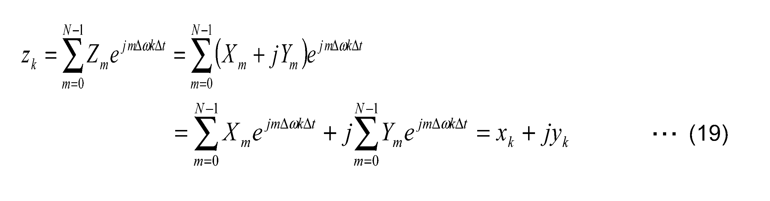
本実施形態の演算装置200では、分離部230が、この複素信号zに対し、第1スペクトルXを逆フーリエ変換した第1実信号xと、第2スペクトルXを逆フーリエ変換した第2実信号yとに分離する。
図13は、第2実施形態に従う複素信号zにおけるインデックスkと実部および虚部との関係の一例を示す表である。図13に示すように、複素信号zは、各インデックスkにおいて、第1実信号xの実数離散信号データxkが実部に配置され、第2実信号yの実数離散信号データykが虚部に配置される。よって、分離部230が、複素信号zの実部から第1スペクトルXを逆フーリエ変換した第1実信号xを分離し、複素信号zの虚部から第2スペクトルYを逆フーリエ変換した第2実信号yを分離することにより、合成スペクトルZを1回逆フーリエ変換した複素信号zから、第1実信号xと第2実信号yの両方を得ることが可能になる。
次に、第1実施形態の演算装置100および本実施形態の演算装置200を適用した実施例について説明する。
(第4実施例)
図14は、第1実施形態に従う演算装置100と第2実施形態に従う演算装置200とを備えるヒルベルト相関演算装置250の構成の一例を示すブロック図である。図14に示すように、ヒルベルト相関演算装置250は、例えば、第1実施形態の演算装置100と、複素共役導出部251と、乗算器252と、ヒルベルト変換部253と、上記した演算装置200と、位相関係導出部254と、直線近似部255と、を備える。
図14は、第1実施形態に従う演算装置100と第2実施形態に従う演算装置200とを備えるヒルベルト相関演算装置250の構成の一例を示すブロック図である。図14に示すように、ヒルベルト相関演算装置250は、例えば、第1実施形態の演算装置100と、複素共役導出部251と、乗算器252と、ヒルベルト変換部253と、上記した演算装置200と、位相関係導出部254と、直線近似部255と、を備える。
なお、ヒルベルト相関演算装置250の演算装置100、複素共役導出部251、および乗算器252は、図10に示す相関演算装置160の演算装置100、複素共役導出部161、および乗算器162と同様であるため、説明を省略する。
ヒルベルト変換部253は、入力値をヒルベルト変換するように、構成されている。ヒルベルト変換部253は、乗算器252からの値を周波数領域でヒルベルト変換し、ヒルベルト変換後の値を演算装置200の合成部210に出力する。
演算装置200の合成部210には、第1スペクトルXとして乗算器252からの値と、第2スペクトルYとしてヒルベルト変換部253からの値とが入力される。
演算装置200の分離部230は、分離した第1実信号xおよび第2実信号yを、位相関係導出部254に出力する。
位相関係導出部254は、複数の入力値の位相関係を導出するように、構成されている。位相関係導出部254は、演算装置200の分離部230から出力された第1実信号xおよび第2実信号yの位相関係を導出し、導出した位相関係を直線近似部255に出力する。
直線近似部255は、位相関係導出部254の出力である位相関係を直線近似によって補間するように、構成されている。直線近似部255は、補完した位相関係を例えば外部に出力する。直線近似部255の出力値は、例えば位相関係が0になる点を相関のピーク位置として使用することが可能である。
このように、本実施形態の演算装置200によれば、逆フーリエ変換するとそれぞれ標本数N(Nは正の整数)を含む実数離散信号になる第1スペクトルXおよび第2スペクトルYを、合成スペクトルZに合成する合成部210を備える。これにより、それぞれ自由度Nを有する第1スペクトルXおよび第2スペクトルYが、自由度2Nの合成スペクトルZに合成される。したがって、自由度Nのスペクトルを逆フーリエ変換していた従来の演算装置と比較して、逆フーリエ変換の演算効率を向上させることができる。また、合成スペクトルZを逆フーリエ変換する逆フーリエ変換部220と、逆フーリエ変換部220の出力である複素信号zに対し、複素信号zの実部から第1スペクトルXを逆フーリエ変換した第1実信号xを分離し、複素信号zの虚部から第2スペクトルYを逆フーリエ変換した第2実信号yを分離する分離部230と、を備える。これにより、合成スペクトルZを1回逆フーリエ変換した複素信号zから、第1実信号xと第2実信号yの両方を得ることが可能になる。したがって、2つのスペクトルをそれぞれ逆フーリエ変換していた従来の演算装置と比較して、逆フーリエ変換の演算回数(演算数)を削減することができる。
なお、本発明は、上記の各実施形態に限定されることなく種々に変形して適用することが可能である。
また、上記発明の各実施形態を通じて説明された実施例や応用例は、用途に応じて適宜に組み合わせて、または変更もしくは改良を加えて用いることができ、本発明は上記した実施形態の記載に限定されるものではない。そのような組み合わせまたは変更もしくは改良を加えた形態も本発明の技術的範囲に含まれ得ることが、特許請求の範囲の記載から明らかである。
1…流量計
100、200…演算装置
110、210…合成部
120…フーリエ変換部
130、230…分離部
220…逆フーリエ変換部
w…合成複素信号
x…第1実信号
y…第2実信号
z…複素信号
W…スペクトル
X…第1スペクトル
Y…第2スペクトル
Z…合成スペクトル
100、200…演算装置
110、210…合成部
120…フーリエ変換部
130、230…分離部
220…逆フーリエ変換部
w…合成複素信号
x…第1実信号
y…第2実信号
z…複素信号
W…スペクトル
X…第1スペクトル
Y…第2スペクトル
Z…合成スペクトル
Claims (6)
- それぞれ標本数N(Nは正の整数)を含む実数離散信号である第1の実信号および第2の実信号に対し、前記第1の実信号を実部とし、前記第2の実信号を虚部とする合成複素信号に合成する合成部と、
前記合成複素信号をフーリエ変換するフーリエ変換部と、
前記フーリエ変換部の出力であるスペクトルを、前記第1の実信号をフーリエ変換した第1のスペクトルと、前記第2の実信号をフーリエ変換した第2のスペクトルとに分離する分離部と、を備える、
演算装置。 - 前記第1の実信号および第2の実信号は、所定のサンプリング周波数で2のべき乗の標本数Nをそれぞれサンプリングしたものであり、
前記分離部は、
前記スペクトルの正の周波数領域における実部と前記スペクトルの負の周波数領域における実部とに基づいて、前記第1のスペクトルの実部と、前記第2のスペクトルの虚部とに分離し、
前記スペクトルの正の周波数領域における虚部と前記スペクトルの負の周波数領域における虚部とに基づいて、前記第1のスペクトルの虚部と、前記第2のスペクトルの実部とに分離する、
請求項1に記載の演算装置。 - 前記フーリエ変換部は、前記合成複素信号を高速フーリエ変換する、
請求項1または2に記載の演算装置。 - 逆フーリエ変換するとそれぞれ標本数N(Nは正の整数)を含む実数離散信号になる第1のスペクトルおよび第2のスペクトルを、合成スペクトルに合成する合成部と、
前記合成スペクトルを逆フーリエ変換する逆フーリエ変換部と、
前記逆フーリエ変換部の出力である複素信号に対し、前記複素信号の実部から前記第1のスペクトルを逆フーリエ変換した第1の実信号を分離し、前記複素信号の虚部から前記第2のスペクトルを逆フーリエ変換した第2の実信号を分離する分離部と、を備える、
演算装置。 - 前記第1の実信号および第2の実信号は、所定のサンプリング周波数で2のべき乗の標本数Nをそれぞれサンプリングしたものであり、
前記合成部は、
前記第2のスペクトルの周波数成分に虚数単位を乗じたものを、前記第1のスペクトルの周波数成分に加算し、前記合成スペクトルを合成する、
請求項4に記載の演算装置。 - 前記逆フーリエ変換部は、前記合成スペクトルを逆高速フーリエ変換する、
請求項4または5に記載の演算装置。
Applications Claiming Priority (2)
| Application Number | Priority Date | Filing Date | Title |
|---|---|---|---|
| JP2015108999A JP2016224625A (ja) | 2015-05-28 | 2015-05-28 | 演算装置 |
| JP2015-108999 | 2015-05-28 |
Publications (1)
| Publication Number | Publication Date |
|---|---|
| WO2016190051A1 true WO2016190051A1 (ja) | 2016-12-01 |
Family
ID=57392768
Family Applications (1)
| Application Number | Title | Priority Date | Filing Date |
|---|---|---|---|
| PCT/JP2016/063416 Ceased WO2016190051A1 (ja) | 2015-05-28 | 2016-04-28 | 演算装置 |
Country Status (2)
| Country | Link |
|---|---|
| JP (1) | JP2016224625A (ja) |
| WO (1) | WO2016190051A1 (ja) |
Citations (1)
| Publication number | Priority date | Publication date | Assignee | Title |
|---|---|---|---|---|
| JPH05268700A (ja) * | 1992-03-17 | 1993-10-15 | Hitachi Ltd | ステレオ聴覚補助装置 |
-
2015
- 2015-05-28 JP JP2015108999A patent/JP2016224625A/ja active Pending
-
2016
- 2016-04-28 WO PCT/JP2016/063416 patent/WO2016190051A1/ja not_active Ceased
Patent Citations (1)
| Publication number | Priority date | Publication date | Assignee | Title |
|---|---|---|---|---|
| JPH05268700A (ja) * | 1992-03-17 | 1993-10-15 | Hitachi Ltd | ステレオ聴覚補助装置 |
Also Published As
| Publication number | Publication date |
|---|---|
| JP2016224625A (ja) | 2016-12-28 |
Similar Documents
| Publication | Publication Date | Title |
|---|---|---|
| Wong | Discrete fourier analysis | |
| Ray | On Haar wavelet operational matrix of general order and its application for the numerical solution of fractional Bagley Torvik equation | |
| CN108701119B (zh) | 定点高动态范围快速傅立叶变换 | |
| US9785614B2 (en) | Fast Fourier transform device, fast Fourier transform method, and recording medium storing fast Fourier transform program | |
| EP2332072A1 (en) | Method and device for computing matrices for discrete fourier transform (dft) coefficients | |
| WO2020003343A1 (ja) | 波源方向推定装置、波源方向推定方法、およびプログラム記録媒体 | |
| KR20120072226A (ko) | 고속 퓨리에 변환기 | |
| US20030041080A1 (en) | Address generator for fast fourier transform processor | |
| JP5269911B2 (ja) | Dft計算用装置 | |
| Carini et al. | Efficient adaptive identification of linear-in-the-parameters nonlinear filters using periodic input sequences | |
| Pariyal et al. | Comparison based analysis of different FFT architectures | |
| US20120059498A1 (en) | Extraction of common and unique components from pairs of arbitrary signals | |
| JP2016224625A (ja) | 演算装置 | |
| JP2001312289A (ja) | 帯域分割用フィルタ回路ならびにそれを用いた信号分析装置および信号加工装置 | |
| Khatua et al. | An efficient DCT-II based harmonic wavelet transform for time-frequency analysis | |
| Vinchurkar et al. | HDL implementation of DFT architectures using Winograd fast Fourier transform algorithm | |
| Horn et al. | m-Fold hypergeometric solutions of linear recurrence equations revisited | |
| van der Byl et al. | Recursive sliding discrete Fourier transform with oversampled data | |
| Bounchaleun | An elementary introduction to fast Fourier transform algorithms | |
| Zanoni | Toom-Cook 8-way for long integers multiplication | |
| WO2013094308A1 (ja) | ディジタルフィルタ回路およびディジタルフィルタ処理方法 | |
| Kober | Fast algorithms for the computation of sliding discrete Hartley transforms | |
| US20150113030A1 (en) | Novel approach for significant improvement of fft performance in microcontrollers | |
| Kovács et al. | Software implementation of the recursive discrete Fourier transform | |
| RU113597U1 (ru) | Цифровой фильтр со смещаемой фазочастотной характеристикой |
Legal Events
| Date | Code | Title | Description |
|---|---|---|---|
| 121 | Ep: the epo has been informed by wipo that ep was designated in this application |
Ref document number: 16799759 Country of ref document: EP Kind code of ref document: A1 |
|
| NENP | Non-entry into the national phase |
Ref country code: DE |
|
| 122 | Ep: pct application non-entry in european phase |
Ref document number: 16799759 Country of ref document: EP Kind code of ref document: A1 |