WO2016189777A1 - 路面標示検出装置、障害要素検出装置、車線検出装置、車線検出方法及びプログラム - Google Patents
路面標示検出装置、障害要素検出装置、車線検出装置、車線検出方法及びプログラム Download PDFInfo
- Publication number
- WO2016189777A1 WO2016189777A1 PCT/JP2016/001168 JP2016001168W WO2016189777A1 WO 2016189777 A1 WO2016189777 A1 WO 2016189777A1 JP 2016001168 W JP2016001168 W JP 2016001168W WO 2016189777 A1 WO2016189777 A1 WO 2016189777A1
- Authority
- WO
- WIPO (PCT)
- Prior art keywords
- edge image
- road marking
- lane
- lane boundary
- road
- Prior art date
- Legal status (The legal status is an assumption and is not a legal conclusion. Google has not performed a legal analysis and makes no representation as to the accuracy of the status listed.)
- Ceased
Links
Images





Classifications
-
- G—PHYSICS
- G06—COMPUTING OR CALCULATING; COUNTING
- G06T—IMAGE DATA PROCESSING OR GENERATION, IN GENERAL
- G06T1/00—General purpose image data processing
-
- G—PHYSICS
- G06—COMPUTING OR CALCULATING; COUNTING
- G06T—IMAGE DATA PROCESSING OR GENERATION, IN GENERAL
- G06T7/00—Image analysis
- G06T7/60—Analysis of geometric attributes
-
- G—PHYSICS
- G08—SIGNALLING
- G08G—TRAFFIC CONTROL SYSTEMS
- G08G1/00—Traffic control systems for road vehicles
- G08G1/16—Anti-collision systems
Definitions
- the present invention relates to a road marking detection device, an obstacle element detection device, a lane detection device, a lane detection method, and a program.
- Patent Document 1 describes that the lane detection device performs a process of extracting a white line (lane boundary line) and a process of extracting a road marking such as a pedestrian crossing.
- this lane detection device In the lane detection device according to the background art, after extracting a white line candidate, a pedestrian crossing, an arrow sign, and a speed sign are individually extracted and excluded from the white line candidate, and a white line is determined.
- this lane detection device is a high-speed and expensive device with an increased image processing amount in order to individually extract road markings such as pedestrian crossings.
- the present invention has been made to solve such problems, and can detect road markings such as a pedestrian crossing together with a simple configuration or method, a road marking detection apparatus, an obstacle element detection apparatus, a lane It is an object to provide a detection device, a lane detection method, and a program.
- an edge image generated based on an image of a road is divided into left and right blocks at the approximate center of the edge image, and a predetermined pixel row of the edge image is divided into left and right blocks in the pixel row.
- a pixel row in which the distance between the pixels closest to the approximate center of each of the blocks is less than or equal to a predetermined value is extracted, and the road surface is based on the ratio of the number of extracted pixel rows to the number of the predetermined pixel rows.
- a road marking detection device including a road marking detection unit that determines the presence or absence of a sign.
- an edge image generated based on an image of a road is divided into left and right blocks at the approximate center of the edge image, and a predetermined pixel row of the edge image is divided into right and left in the pixel row.
- a failure element detection device including a failure element detection unit that determines the presence or absence of a failure element including a vehicle.
- a lane boundary detection unit that detects a lane boundary candidate from an edge image generated based on an image obtained by imaging a road, and the edge image is divided into left and right blocks at substantially the center of the edge image. Dividing and extracting, from the predetermined pixel row of the edge image, a pixel row whose distance between the pixels closest to the approximate center of each of the left and right blocks in the pixel row is a predetermined value or less, The road marking detection unit that determines the presence or absence of road marking based on the ratio of the number to the number of the predetermined pixel rows, and the lane boundary detection unit when the road marking detection unit determines that there is no road marking.
- a lane detection device including a determination unit that determines a lane boundary candidate detected by the vehicle as a lane boundary.
- a step of detecting a lane boundary line candidate from an edge image generated based on an image obtained by imaging a road and a step of dividing the edge image into left and right blocks at substantially the center of the edge image; Extracting from the predetermined pixel row of the edge image a pixel row in which the distance between the pixels closest to the approximate center of each of the left and right blocks in the pixel row is equal to or less than a predetermined value; and The step of determining the presence or absence of road marking based on the ratio of the number to the number of the predetermined pixel rows, and determining that there is no road marking, the detected lane boundary line candidate is determined as the lane boundary line And a lane detection method.
- the computer detects a lane boundary line candidate from an edge image generated based on an image of a road, and divides the edge image into left and right blocks at the approximate center of the edge image. And a procedure for extracting, from a predetermined pixel row of the edge image, a pixel row in which the distance between the pixels closest to the approximate center of each of the left and right blocks in the pixel row is a predetermined value or less, and Based on the ratio of the number of pixel rows to the number of the predetermined pixel rows, the procedure for judging the presence or absence of road markings, and the detected lane boundary line candidates when it is judged that there are no road markings, And a program for executing the procedure for judging.
- a road marking detection device an obstacle element detection device, a lane detection device, a lane detection method, and a program that collectively detect road markings such as pedestrian crossings with a simple configuration or method.
- FIG. 1 is a block diagram showing a schematic configuration of a lane detection system 1 according to an embodiment. It is a flowchart which shows the process sequence of the lane detection method which concerns on embodiment. It is a flowchart which shows the detailed process sequence of the center side edge image generation process which concerns on embodiment. It is a flowchart which shows the detailed process sequence of the road marking detection process which concerns on embodiment. It is an example of a bird view image, a thin line edge image, and a center side edge image when there is no road marking according to the embodiment. It is an example of a bird view image, a thin line edge image, and a center side edge image when the road marking according to the embodiment is a pedestrian crossing.
- a lane detection system according to the present embodiment will be described with reference to the drawings.
- a road center line In order to make the explanation easy to understand, it is called a road center line, a lane boundary line, a road outer line, etc.
- road marking I there is a pedestrian crossing, maximum speed, pedestrian crossing or bicycle crossing zone, place name, direction of travel, etc., and what is drawn in white on the road surface is collectively called road marking I will decide.
- the above-described lane boundary line is not included in the road marking.
- FIG. 1 is a block diagram showing a schematic configuration of a lane detection system 1 according to the present embodiment.
- the lane detection system 1 includes a camera 10, a lane detection unit 20, a monitor 30, a speaker 40, and the like.
- the camera 10 is an in-vehicle camera that captures a road in the traveling direction of the host vehicle, that is, in front of or behind the host vehicle.
- the lane detection unit 20 performs various image processing on the image input from the camera 10 and detects a lane in which the host vehicle travels, that is, a travel lane. Further, the lane detection unit 20 outputs a warning signal to the monitor 30 and the speaker 40 when the host vehicle deviates from the lane.
- the monitor 30 inputs a warning signal and outputs a warning display, and the speaker 40 inputs the warning signal and reproduces a warning sound, and notifies each driver of the danger.
- the lane detection unit 20 includes a lane boundary detection unit 21, a road marking detection unit 22, a determination unit 23, and the like.
- the lane boundary detection unit 21 performs edge extraction, Hough conversion, etc., extracts straight lines, and detects lane boundary candidates.
- the road marking detection unit 22 collectively detects road markings such as a pedestrian crossing, a maximum speed, a pedestrian crossing or a bicycle crossing zone.
- the determination unit 23 determines a lane based on the detection results of the lane boundary detection unit 21 and the road marking detection unit 22. Specific operation of the lane detector 20 will be described later.
- achieves is realizable by making a program run by control of the arithmetic unit (not shown) with which the lane detection part 20 which is a computer is provided, for example. More specifically, the lane detection unit 20 is realized by loading a program stored in a storage unit (not shown) into a main storage device (not shown) and executing the program under the control of the arithmetic unit.
- Each constituent element is not limited to being realized by software by a program, but may be realized by any combination of hardware, firmware, and software.
- Non-transitory computer readable media include various types of tangible storage media (tangible storage medium).
- Examples of non-transitory computer-readable media include magnetic recording media (eg flexible disks, magnetic tapes, hard disk drives), magneto-optical recording media (eg magneto-optical discs), CD-ROMs (Read Only Memory), CD-Rs, CD-R / W, semiconductor memory (for example, mask ROM, PROM (Programmable ROM), EPROM (Erasable ROM), flash ROM, RAM (random access memory)) are included.
- the program may be supplied to a computer by various types of temporary computer readable media.
- Examples of transitory computer readable media include electrical signals, optical signals and electromagnetic waves.
- the temporary computer-readable medium can supply the program to the computer via a wired communication path such as an electric wire and an optical fiber, or a wireless communication path.
- FIG. 2 is a flowchart showing a processing procedure of the lane detection method according to the present embodiment.
- the processes related to steps S10 to S150 shown in FIG. 2 are mainly executed by the lane boundary detection unit 21, and the processes related to steps S100 to S110 are mainly performed on the road surface.
- the sign detection unit 22 executes and the processes related to steps S120 to S150 are mainly executed by the determination unit 23, but the sharing of these processes is not limited to the above.
- the lane detector 20 inputs a color image in front of the host vehicle photographed by the camera 10 (step S10). Then, the input color image is converted into a grayscale image having only luminance information (step S20). Of course, it is also possible to input a grayscale image from the camera 10 and omit step S20.
- a process of resizing the grayscale image to reduce the amount of computation for example, an image of horizontal 640 pixels ⁇ vertical 480 pixels (x direction 640 pixels ⁇ y direction 480 pixels) is converted into an image of 320 pixels vertical ⁇ 240 pixels horizontal.
- Reduction processing is performed, and the resized image is converted into a bird view image (a bird's-eye view image looking down from directly above) (step S30).
- noise reduction processing such as Gaussian filter processing, is performed on the bird view image (step S40). This process has the effect of facilitating extraction of edges as well as the effect of noise reduction.
- edge extraction processing is performed on the noise-reduced image using a Sobel filter or the like (step S50).
- the boundary (edge) between the lane boundary line and the asphalt surface can be appropriately extracted by this processing.
- an edge with a large luminance difference is a color close to white (luminance: 255), and an edge with a small luminance difference is a color close to black (luminance: 0).
- binarization processing is performed in order to leave only edges with a large luminance difference (step S60).
- a pixel having a luminance value larger than a predetermined threshold is set to white
- a pixel having a luminance value lower than the threshold is set to black
- a binary image (monochrome image) having only a large luminance difference is obtained. ) Is obtained.
- the obtained binarized image is thinned, and the thick line is thinned to obtain a thinned edge image (step S70).
- the thinned edge image is, for example, an image of 320 ⁇ 240 pixels
- the process which detects a lane boundary line candidate is performed on the one hand using the thinned edge image obtained, and the process which detects a road marking is performed on the other hand.
- a Hough conversion process is performed on the obtained thinned edge image to extract a straight line (step S80).
- the extracted straight line may include not only the edge of the lane boundary line but also the edge of the preceding vehicle or guardrail, the edge of the road marking, and the like.
- the lane boundary line is “the straight line is almost vertical (substantially parallel to the vertical direction of the image)”, “the distance between the left straight line and the right straight line is the road width on the road surface (3-4 m).
- the right lane boundary line candidate is detected as a set (pair) (step S90).
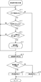
- FIG. 3 is a flowchart showing a detailed processing procedure of the center edge image generation processing according to the present embodiment.
- the center-side edge image generation process (step S100) is specifically composed of steps S101 to S104. Step S100 is not followed by steps S101 to S104. By generating the edge image near the center, it becomes easy to detect the road marking from the thinned edge image.
- the obtained thinned edge image is divided into a left block and a right block at the approximate center of the image (step S101). For example, if the thinned edge image is an image of 320 ⁇ 240 pixels, the left block and the right block are each a block of 160 ⁇ 240 pixels. Then, for a certain y coordinate (a certain pixel row), it is determined whether there are a plurality of edges in the left block or the right block (steps S102 and S103).
- FIG. 4 is a flowchart showing a detailed processing procedure of road marking detection processing according to the present embodiment.
- the road marking detection process (step S110) includes steps S111 to S118 in detail. First, it is determined whether there is an edge in both the left and right blocks with respect to a certain y coordinate (a certain pixel row) of the center-side edge image (step S111: Yes, step S112).
- step S113 it is determined whether the edge interval is equal to or smaller than a predetermined value (or less than a predetermined value) (step S113).
- a predetermined value a value corresponding to an assumed lane width (travel lane width, 3 to 4 m) of the road surface is used. If the edge interval is less than or equal to the predetermined value (or less than the predetermined value) (Yes in step S113), 1 is added to the road marking counter value (step S114), and the process returns to step S111.
- step S112 If both the left and right blocks do not have an edge (No in step S112), or if the edge interval is not less than a predetermined value (or less than the predetermined value) (No in step S113), the process returns to step S111 as it is. .
- the same processing (steps S111 to S114) is performed for the next y coordinate (next pixel row) of the center edge image.
- step S111 the above processing (steps S111 to S114) is performed for all y coordinates (all pixel rows) of the center edge image. If there is no next y coordinate (No in step S111), road marking The rate is calculated (step S115).
- the road marking rate is defined by the ratio of the road marking counter value to the height of the center edge image (for example, 240 if the center edge image is an image of 320 ⁇ 240 pixels). If the road marking rate is greater than or equal to a certain threshold value, it can be determined that there is a high possibility that a road marking exists.
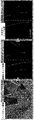
- FIG. 5 is an example of a bird view image, a thinned edge image, and a center edge image when there is no road marking according to the present embodiment.
- the image after bird view conversion in step S30, the thinned edge image after dividing into the left and right blocks in step S101, and the center edge image after the road marking rate calculation in step S115 are arranged.
- the bird view image shows two lanes that gently curve to the left and the roadside band on the left, the preceding vehicle in the left lane, two vehicles in the right lane, and the left side of the roadside band Each guardrail is shown.
- the vehicle is on the left lane, the left lane boundary is partially cut off, and the right lane boundary is largely interrupted.
- the thinned edge image there is a dotted line that divides the thinned edge image into left and right blocks in the center vertical direction, and in order from the left, the guardrail, the left and right lane boundary lines, and the edge of the vehicle in the right lane Is reflected.
- dotted lines that are divided into left and right blocks are similarly shown, and the edges of the left and right lane boundary lines and a part of the right lane of the vehicle are shown without being deleted.
- the road marking counter value and the road marking rate (inside []) of this image are shown in the lower left corner of the center-side edge image, and the road marking counter value when there is no road marking is 0. The rate is also 0%.
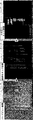
- FIG. 6 is an example of a bird view image, a thinned edge image, and a central edge image when the road marking according to the present embodiment is a pedestrian crossing.
- the dotted lines for dividing the thinned edge image and the center-side edge image into the left and right blocks are omitted (the same dotted lines are also omitted in FIGS. 7 to 10).
- a pedestrian crossing is shown in the lower center of the bird view image, and an edge of the pedestrian crossing is shown in the lower center of the thinned edge image.
- the edge image close to the center when the edge interval is equal to or smaller than a predetermined value (Yes in step S113), the space between the edges is filled (the edges are also painted similarly in FIGS. 7 to 10).
- the road marking counter value is 34 and the road marking rate is 14%.
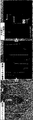
- FIG. 7 is an example of a bird view image, a thinned edge image, and a center edge image when the road marking according to the present embodiment is at the maximum speed.
- the maximum speed “40” is displayed at the center of the bird view image, and the lane boundary line is displayed to the right of the maximum speed.
- the road marking counter value is 91 and the road marking rate is 37%.
- FIG. 8 is an example of a bird view image, a thinned edge image, and a center edge image when the road marking according to the present embodiment has a pedestrian crossing or a bicycle crossing zone.
- a road marking with a pedestrian crossing or a bicycle crossing zone is displayed at the lower center of the bird view image, and a lane boundary line is shown on the left and right.
- the road marking counter value is 67 and the road marking rate is 27%.
- FIG. 9 is an example of a bird view image, a thinned edge image, and a center edge image when the road marking according to the present embodiment is a place name.
- the place names “Omiya” and “Ginza” appear in the center of the bird view image, and multiple lane boundaries appear on the left and right.
- the road marking counter value is 114, and the road marking rate is 47%.
- FIG. 10 is an example of a bird view image, a thinned edge image, and a center edge image when the road marking according to the present embodiment is in the traveling direction.
- arrows indicating the direction of travel “left turn”, “straight or left turn”, and “right turn” are displayed in order from the left.
- the road marking counter value is 63 and the road marking rate is 26%.
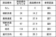
- FIG. 11 is a diagram showing an example of the result of the road marking detection process according to the present embodiment.
- FIG. 11 summarizes the processing results of the images shown in FIGS.
- step S115 it is determined whether the road marking rate calculated in step S115 is equal to or greater than a predetermined threshold (for example, 10%) (step S116). If the road marking rate is greater than or equal to a predetermined threshold (Yes in step S116), it is determined that a road marking has been detected or there is a road marking (step S117). If the road marking rate is not equal to or greater than the predetermined threshold (No in step S116), it is determined that no road marking has been detected or there is no road marking (step S118). Then, the road marking detection process (step S110) ends.
- a predetermined threshold for example, 10%
- FIG. 12 is a flowchart showing a detailed processing procedure of the lane determination processing according to the present embodiment. Specifically, the lane determination process (step S120) includes steps S121 to S123.
- step S121 it is determined whether a road marking has been detected in step S110 (step S121).
- the lane is determined based on the left and right lane boundary line candidates detected in Step S90 (Step S122). If a road marking is detected (Yes in step S121), the left and right lane boundary line candidates detected in step S90 are highly likely to be erroneously detected, so the lanes up to the previous frame (host vehicle lane) (Step S123) to reduce malfunctions. Then, the lane determination process (step S120) ends.
- step S130 it is determined whether the host vehicle deviates from the lane.
- the determination method here may be a known method. If the host vehicle deviates from the lane (Yes in step S130), the warning signal is output as described above (step S140), and it is determined whether the process is continued (step S150). If the host vehicle does not depart from the lane (No in step S130), it is determined whether or not to continue the process (step S150). When the process is continued (Yes in step S150), the process returns to step S10. When the process is not continued (No in step S150), the vehicle detection method is terminated.
- a lane boundary line may be selected from left and right lane boundary line candidates close to the position of the lane boundary line up to the previous frame.
- each process is performed using all the y coordinates (all pixel rows) of the image input from the camera 10.
- Each process may be performed using some pixel rows).
- y coordinates (pixels) that are part of the thinned edge image generated in step S70 or that are separated at a predetermined interval. (Line) may be used for processing.
- the lane boundary detection unit detects the left and right lane boundary candidates in pairs (pairs), but the lane boundary detection unit detects one of the left and right lane boundary candidates. Then, the lane may be detected. For example, the left and right lane boundary lines are disappearing (or disappearing) and only one lane boundary line candidate can be detected.
- the determination unit detects the lane by estimating the position of the other lane boundary line from the detected one lane boundary line candidate. This is based on the fact that the lane width does not change suddenly and is often 3-4 m. The determination unit stops the process of estimating the position of the other lane boundary line when the road marking is detected, and the other lane when the road marking is not detected. You may perform the process which estimates the position of a boundary line.
- an in-vehicle camera is used as the camera 10.
- a camera other than the in-vehicle camera for example, a camera that can shoot from the sky may be used.
- the bird view conversion process (step S30) of the input image is unnecessary.
- the resizing process (step S30), the noise reduction process (step S40), the binarization process (step S60), the thinning process (step S70), the center edge image generation process (step S100), and the like are also performed. It can be omitted in consideration of detection accuracy and processing speed of line candidates and road markings.
- the lane detection method according to the present embodiment when the inter-vehicle distance from the preceding vehicle is small, edges such as the rear wiper of the preceding vehicle may gather at the center of the image and the road marking rate may increase.
- the lane detection method according to the present embodiment is configured as a preceding vehicle detection method, a failure element detection method for detecting a failure element that may cause erroneous lane detection such as road markings and preceding vehicles, and the like. May be.
- the lane detection system according to the present embodiment may be configured as a road marking detection device, a lane detection device, a lane detection method, a lane detection program, and the like.
- the road marking detection apparatus divides an edge image generated based on an image obtained by imaging a road into right and left blocks at a substantially center of the edge image, and performs predetermined processing on the edge image.
- a road marking detection unit 22 that determines the presence / absence of road marking based on the ratio of the number to the number is provided.
- the obstacle element detection device divides an edge image generated based on an image obtained by capturing a road into right and left blocks at the approximate center of the edge image, and starts from a predetermined pixel row of the edge image.
- a pixel row in which the distance between the pixels closest to the approximate center of each of the left and right blocks in the pixel row is less than or equal to a predetermined value is extracted, and the number of extracted pixel rows occupies the number of the predetermined pixel rows
- a failure element detection unit that determines the presence or absence of a failure element including a preceding vehicle based on the ratio is provided. With such a configuration, it is possible to easily detect an obstacle element including a preceding vehicle with a simple configuration.
- the lane detection device includes a lane boundary detection unit 21 that detects a lane boundary candidate from an edge image generated based on an image obtained by capturing a road, and the edge image is an abbreviation of the edge image. Divide into left and right blocks at the center, and extract from the predetermined pixel row of the edge image a pixel row whose distance between the pixels closest to the approximate center of each of the left and right blocks in the pixel row is a predetermined value or less. Based on the ratio of the number of extracted pixel rows to the number of the predetermined pixel rows, the road marking detection unit 22 that determines the presence / absence of road marking, and the road marking detection unit 22 determines that there is no road marking.
- a lane boundary line candidate detected by the lane boundary line detection unit 21 is provided with a determination unit 23 that determines the lane boundary line as a lane boundary line.
- the lane detection method includes a step S90 of detecting a lane boundary line candidate from an edge image generated based on an image obtained by imaging a road, and the edge image is moved to the left and right at the approximate center of the edge image.
- steps S116 to S118 for determining the presence or absence of road marking based on the ratio of the number of extracted pixel rows to the number of the predetermined pixel rows, and no road marking
- steps S121 and S122 for determining a lane boundary candidate as a lane boundary.
- the lane detection system or the lane detection method according to the embodiment is applied to a vehicle or the like and can collectively detect road markings such as a pedestrian crossing and has industrial applicability.
- Lane detection system 10 Camera 20 Lane detection unit 21 Lane boundary detection unit 22 Road marking detection unit 23 Determination unit 30 Monitor 40 Speaker
Landscapes
- Physics & Mathematics (AREA)
- General Physics & Mathematics (AREA)
- Engineering & Computer Science (AREA)
- Theoretical Computer Science (AREA)
- Geometry (AREA)
- Computer Vision & Pattern Recognition (AREA)
- Traffic Control Systems (AREA)
- Image Analysis (AREA)
- Image Processing (AREA)
Abstract
路面標示検出装置は、道路を撮像した画像に基づいて生成したエッジ画像を、当該エッジ画像の略中央で左右のブロックに分割し、当該エッジ画像の所定の画素行から、当該画素行における左右のブロックそれぞれの当該略中央に最も近い画素の間の距離が所定値以下である画素行を抽出し、抽出した画素行の数が、当該所定の画素行の数に占める割合に基づいて、路面標示の有無を判断する路面標示検出部(22)を備えるもので、簡単な構成で横断歩道などの路面標示をまとめて検出することができる。
Description
本発明は路面標示検出装置、障害要素検出装置、車線検出装置、車線検出方法及びプログラムに関する。
自車両の位置を判断するために車線境界線などを検出する車線検出装置が開発されている。例えば、特許文献1には、車線検出装置が、白線(車線境界線)を抽出する処理と、横断歩道などの路面標示を抽出する処理とを行うことが記載されている。
背景技術に係る車線検出装置では、白線候補を抽出した後に、横断歩道、矢印標示、速度標示をそれぞれ個別に抽出して上記白線候補から除外し、白線を決定している。つまり、この車線検出装置は、横断歩道などの路面標示を個別に抽出するために、画像処理量が増大し、高速で高価な装置になっていた。
本発明は、このような問題を解決するためになされたものであり、簡単な構成又は方法で横断歩道などの路面標示をまとめて検出することができる路面標示検出装置、障害要素検出装置、車線検出装置、車線検出方法及びプログラムを提供することを目的とする。
そこで、本実施の形態は、道路を撮像した画像に基づいて生成したエッジ画像を当該エッジ画像の略中央で左右のブロックに分割し、当該エッジ画像の所定の画素行から、当該画素行における左右のブロックそれぞれの当該略中央に最も近い画素の間の距離が所定値以下である画素行を抽出し、抽出した画素行の数が、当該所定の画素行の数に占める割合に基づいて、路面標示の有無を判断する路面標示検出部を備えた路面標示検出装置を提供する。
また、本実施の形態は、道路を撮像した画像に基づいて生成したエッジ画像を当該エッジ画像の略中央で左右のブロックに分割し、当該エッジ画像の所定の画素行から、当該画素行における左右のブロックそれぞれの当該略中央に最も近い画素の間の距離が所定値以下である画素行を抽出し、抽出した画素行の数が、当該所定の画素行の数に占める割合に基づいて、先行車両を含む障害要素の有無を判断する障害要素検出部を備えた障害要素検出装置を提供する。
また、本実施の形態は、道路を撮像した画像に基づいて生成したエッジ画像から車線境界線候補を検出する車線境界線検出部と、当該エッジ画像を当該エッジ画像の略中央で左右のブロックに分割し、当該エッジ画像の所定の画素行から、当該画素行における左右のブロックそれぞれの当該略中央に最も近い画素の間の距離が所定値以下である画素行を抽出し、抽出した画素行の数が、当該所定の画素行の数に占める割合に基づいて、路面標示の有無を判断する路面標示検出部と、路面標示検出部が路面標示が無いと判断したときに、車線境界線検出部が検出した車線境界線候補を車線境界線と判断する判定部とを備えた車線検出装置を提供する。
また、本実施の形態は、道路を撮像した画像に基づいて生成したエッジ画像から車線境界線候補を検出するステップと、当該エッジ画像を当該エッジ画像の略中央で左右のブロックに分割するステップと、当該エッジ画像の所定の画素行から、当該画素行における左右のブロックそれぞれの当該略中央に最も近い画素の間の距離が所定値以下である画素行を抽出するステップと、抽出した画素行の数が、当該所定の画素行の数に占める割合に基づいて、路面標示の有無を判断するステップと、路面標示が無いと判断したときに、検出した車線境界線候補を車線境界線と判断するステップとを有する車線検出方法を提供する。
また、本実施の形態は、コンピュータに、道路を撮像した画像に基づいて生成したエッジ画像から車線境界線候補を検出する手順と、当該エッジ画像を当該エッジ画像の略中央で左右のブロックに分割する手順と、当該エッジ画像の所定の画素行から、当該画素行における左右のブロックそれぞれの当該略中央に最も近い画素の間の距離が所定値以下である画素行を抽出する手順と、抽出した画素行の数が、当該所定の画素行の数に占める割合に基づいて、路面標示の有無を判断する手順と、路面標示が無いと判断したときに、検出した車線境界線候補を車線境界線と判断する手順とを実行させるためのプログラムを提供する。
本実施の形態により、簡単な構成又は方法で横断歩道などの路面標示をまとめて検出する路面標示検出装置、障害要素検出装置、車線検出装置、車線検出方法及びプログラムを提供することができる。
以下、図面を参照して本実施の形態に係る車線検出システムについて説明する。
なお、本明細書では、説明を分りやすくするために、車道中央線、車線境界線、車道外側線などと呼ばれ、路面に白色、黄色などの線又は点線で描かれたものを総称して車線境界線ということにし、これに対して、横断歩道、最高速度、横断歩道又は自転車横断帯あり、地名、進行方向などを示し、路面に白色などで描かれたものを総称して路面標示ということにする。そして、本明細書では、上記総称する車線境界線は、路面標示に含めないことにする。
なお、本明細書では、説明を分りやすくするために、車道中央線、車線境界線、車道外側線などと呼ばれ、路面に白色、黄色などの線又は点線で描かれたものを総称して車線境界線ということにし、これに対して、横断歩道、最高速度、横断歩道又は自転車横断帯あり、地名、進行方向などを示し、路面に白色などで描かれたものを総称して路面標示ということにする。そして、本明細書では、上記総称する車線境界線は、路面標示に含めないことにする。
また、車線境界線、路面標示などの名称、形状などについては、次の電子的技術情報などを参照されたい。
国土交通省,”道路技術基準の体系”,[online],[平成27年5月28日検索],インターネット<http://www.mlit.go.jp/road/sign/kijyun/taikei01.html>
国土交通省,”道路技術基準の体系”,[online],[平成27年5月28日検索],インターネット<http://www.mlit.go.jp/road/sign/kijyun/taikei01.html>
まず、本実施の形態に係る車線検出システムの構成について説明する。
図1は、本実施の形態に係る車線検出システム1の概略構成を示すブロック図である。
車線検出システム1は、カメラ10、車線検出部20、モニタ30、スピーカ40などを備える。
カメラ10は、自車両の前方又は後方、すなわち、自車両の走行方向の道路を撮影する車載カメラである。
図1は、本実施の形態に係る車線検出システム1の概略構成を示すブロック図である。
車線検出システム1は、カメラ10、車線検出部20、モニタ30、スピーカ40などを備える。
カメラ10は、自車両の前方又は後方、すなわち、自車両の走行方向の道路を撮影する車載カメラである。
車線検出部20は、カメラ10から入力した画像に対して種々の画像処理を行い、自車両が走行する車線、つまり、走行レーンを検出する。また、車線検出部20は、自車両が車線から逸脱しているときは、モニタ30、スピーカ40に対して警告信号を出力する。
モニタ30は警告信号を入力して警告表示を出力し、スピーカ40は警告信号を入力して警告音を再生し、それぞれ運転者に危険を通知する。
モニタ30は警告信号を入力して警告表示を出力し、スピーカ40は警告信号を入力して警告音を再生し、それぞれ運転者に危険を通知する。
また、車線検出部20は、車線境界線検出部21、路面標示検出部22、判定部23などを備える。
車線境界線検出部21は、エッジ抽出、Hough変換などを行い、直線を抽出し、車線境界線候補を検出する。
路面標示検出部22は、横断歩道、最高速度、横断歩道又は自転車横断帯ありなどの路面標示をまとめて検出する。
判定部23は、車線境界線検出部21及び路面標示検出部22の検出結果に基づいて、車線を判定する。
車線検出部20の具体的な動作については後述する。
車線境界線検出部21は、エッジ抽出、Hough変換などを行い、直線を抽出し、車線境界線候補を検出する。
路面標示検出部22は、横断歩道、最高速度、横断歩道又は自転車横断帯ありなどの路面標示をまとめて検出する。
判定部23は、車線境界線検出部21及び路面標示検出部22の検出結果に基づいて、車線を判定する。
車線検出部20の具体的な動作については後述する。
なお、車線検出部20が実現する各構成要素は、例えば、コンピュータである車線検出部20が備える演算装置(図示せず)の制御によって、プログラムを実行させることによって実現できる。より具体的には、車線検出部20は、記憶部(図示せず)に格納されたプログラムを主記憶装置(図示せず)にロードし、演算装置の制御によってプログラムを実行して実現する。また、各構成要素は、プログラムによるソフトウェアで実現することに限ることなく、ハードウェア、ファームウェア又はソフトウェアのうちのいずれかの組み合わせ等により実現しても良い。
上述したプログラムは、様々なタイプの非一時的なコンピュータ可読媒体(non-transitory computer readable medium)を用いて格納され、コンピュータに供給することができる。非一時的なコンピュータ可読媒体は、様々なタイプの実体のある記録媒体(tangible storage medium)を含む。非一時的なコンピュータ可読媒体の例は、磁気記録媒体(例えばフレキシブルディスク、磁気テープ、ハードディスクドライブ)、光磁気記録媒体(例えば光磁気ディスク)、CD-ROM(Read Only Memory)、CD-R、CD-R/W、半導体メモリ(例えば、マスクROM、PROM(Programmable ROM)、EPROM(Erasable PROM)、フラッシュROM、RAM(random access memory))を含む。
また、プログラムは、様々なタイプの一時的なコンピュータ可読媒体(transitory computer readable medium)によってコンピュータに供給されても良い。一時的なコンピュータ可読媒体の例は、電気信号、光信号及び電磁波を含む。一時的なコンピュータ可読媒体は、電線及び光ファイバ等の有線通信路、又は無線通信路を介して、プログラムをコンピュータに供給できる。
続いて、本実施の形態に係る車線検出システム1の動作について説明する。ここでは、車線検出部20の動作、すなわち、車線検出方法について特に説明する。
図2は、本実施の形態に係る車線検出方法の処理手順を示すフローチャートである。
なお、図2に示すステップS10~ステップS150に係る処理のうち、ステップS10~ステップS90に係る処理は主に車線境界線検出部21が実行し、ステップS100~ステップS110に係る処理は主に路面標示検出部22が実行し、ステップS120~ステップS150に係る処理は主に判定部23が実行するが、これらの処理の分担は上記に限られるものではない。
図2は、本実施の形態に係る車線検出方法の処理手順を示すフローチャートである。
なお、図2に示すステップS10~ステップS150に係る処理のうち、ステップS10~ステップS90に係る処理は主に車線境界線検出部21が実行し、ステップS100~ステップS110に係る処理は主に路面標示検出部22が実行し、ステップS120~ステップS150に係る処理は主に判定部23が実行するが、これらの処理の分担は上記に限られるものではない。
まず、車線検出部20は、動作を開始すると、カメラ10が撮影した自車両の前方のカラー画像を入力する(ステップS10)。
そして、入力したカラー画像を輝度情報のみのグレースケール画像へ変換する(ステップS20)。もちろん、カメラ10からグレースケール画像を入力して、ステップS20を省略することもできる。
そして、入力したカラー画像を輝度情報のみのグレースケール画像へ変換する(ステップS20)。もちろん、カメラ10からグレースケール画像を入力して、ステップS20を省略することもできる。
そして、演算量削減のためにグレースケール画像をリサイズする処理、例えば、横640画素×縦480画素(x方向640画素×y方向480画素)の画像を縦320画素×横240画素の画像にする縮小処理を行い、更に、リサイズ画像をバードビュー画像(真上から見下ろした俯瞰画像)に変換する(ステップS30)。
そして、バードビュー画像にノイズリダクション処理、例えば、ガウシアンフィルタなどの処理を行う(ステップS40)。この処理はノイズリダクションの効果とともに、エッジを抽出しやすくする効果がある。
そして、バードビュー画像にノイズリダクション処理、例えば、ガウシアンフィルタなどの処理を行う(ステップS40)。この処理はノイズリダクションの効果とともに、エッジを抽出しやすくする効果がある。
そして、ノイズリダクションした画像にSobelフィルタなどでエッジ抽出処理を行う(ステップS50)。一般に、車線境界線の白線とアスファルト面とは輝度差が大きいので、この処理により車線境界線とアスファルト面との境界(エッジ)を適切に抽出することができる。
ステップS50のエッジ抽出処理によって得られたグレースケールのエッジ画像は、輝度差が大きいエッジは白(輝度:255)に近い色、輝度差が小さいエッジは黒(輝度:0)に近い色となっている。ここで、輝度差の大きいエッジのみを残すために、2値化処理を行う(ステップS60)。2値化処理により、所定の閾値よりも大きい輝度値を有する画素を白にし、同閾値よりも小さい輝度値を有する画素を黒にして、輝度差の大きいエッジのみの2値化画像(白黒画像)が得られる。
ステップS50のエッジ抽出処理によって得られたグレースケールのエッジ画像は、輝度差が大きいエッジは白(輝度:255)に近い色、輝度差が小さいエッジは黒(輝度:0)に近い色となっている。ここで、輝度差の大きいエッジのみを残すために、2値化処理を行う(ステップS60)。2値化処理により、所定の閾値よりも大きい輝度値を有する画素を白にし、同閾値よりも小さい輝度値を有する画素を黒にして、輝度差の大きいエッジのみの2値化画像(白黒画像)が得られる。
そして、得られた2値化画像の細線化処理を行い、太い線を細くして細線化エッジ画像を得る(ステップS70)。なお、本明細書では、細線化エッジ画像が例えば320×240画素の画像であれば、画像の左上画素の座標を(x、y)=(0,0)、右下画素の座標を(x、y)=(319,239)と定義する。
そして、得られた細線化エッジ画像を用いて、一方では車線境界線候補を検出する処理を行い、他方では路面標示を検出する処理を行う。
そして、得られた細線化エッジ画像を用いて、一方では車線境界線候補を検出する処理を行い、他方では路面標示を検出する処理を行う。
車線境界線候補を検出するときは、まず、得られた細線化エッジ画像にHough変換処理を行い、直線を抽出する(ステップS80)。この抽出した直線には、車線境界線のエッジだけでなく、先行車両やガードレールのエッジ、路面標示のエッジなどが含まれることがある。そこで、車線境界線が、「直線が垂直に近い(画像の縦方向に対して略平行である)」、「左の直線と右の直線との間隔が、路面での道路幅(3~4m程度)に対応する」、「時間的に連続する(連続するフレームで同じような位置にある)」などの特徴を有することを用いて、抽出した直線の中から、左の車線境界線候補及び右の車線境界線候補を組み(ペア)で検出する(ステップS90)。
また、路面標示を検出するときは、ステップS70で得られた細線化エッジ画像から中央寄りエッジ画像を生成し(ステップS100)、中央寄りエッジ画像から路面標示を検出する(ステップS110)。
図3は、本実施の形態に係る中央寄りエッジ画像生成処理の詳細な処理手順を示すフローチャートである。中央寄りエッジ画像生成処理(ステップS100)は、詳細には、ステップS101~ステップS104で構成される。ステップS100の後に、ステップS101~ステップS104が続くのではない。中央寄りエッジ画像を生成することで、細線化エッジ画像から路面標示を検出しやすくなる。
図3は、本実施の形態に係る中央寄りエッジ画像生成処理の詳細な処理手順を示すフローチャートである。中央寄りエッジ画像生成処理(ステップS100)は、詳細には、ステップS101~ステップS104で構成される。ステップS100の後に、ステップS101~ステップS104が続くのではない。中央寄りエッジ画像を生成することで、細線化エッジ画像から路面標示を検出しやすくなる。
まず、得られた細線化エッジ画像を画像の略中央で左ブロックと右ブロックとに分割する(ステップS101)。例えば、細線化エッジ画像が320×240画素の画像であれば、左ブロック、右ブロックはそれぞれ160×240画素のブロックになる。
そして、あるy座標(ある画素行)について、左ブロック又は右ブロックに複数のエッジがあるか判断する(ステップS102、ステップS103)。
そして、あるy座標(ある画素行)について、左ブロック又は右ブロックに複数のエッジがあるか判断する(ステップS102、ステップS103)。
左ブロック又は右ブロックに複数のエッジがある場合には(ステップS103のYes)、複数のエッジのうちの画像中央寄りの1画素、例えば、細線化エッジ画像が320×240画素の画像であれば、左ブロックでは略中央のx=159に最も近い1画素、右ブロックでは略中央のx=160に最も近い1画素を残して、残りの画素を削除し(ステップS104)、ステップS102に戻る。
また、左ブロック及び右ブロックに複数のエッジがない場合には(ステップS103のNo)、そのままステップS102に戻る。
また、左ブロック及び右ブロックに複数のエッジがない場合には(ステップS103のNo)、そのままステップS102に戻る。
そして、次のy座標(次の画素行)についても、同様の処理(ステップS102~ステップS104)を行う。
そして、中央寄りエッジ画像の全てのy座標(例えば、左ブロック、右ブロックがそれぞれ160×240画素のブロックであれば、y=0,1,2・・・238,239)について、上記の処理(ステップS102~ステップS104)を行い、中央寄りエッジ画像を生成する。
そして、次のy座標がない場合には(ステップS102のNo)、中央寄りエッジ画像生成処理(ステップS100)を終了して、路面標示検出処理(ステップS110)に進む。
そして、中央寄りエッジ画像の全てのy座標(例えば、左ブロック、右ブロックがそれぞれ160×240画素のブロックであれば、y=0,1,2・・・238,239)について、上記の処理(ステップS102~ステップS104)を行い、中央寄りエッジ画像を生成する。
そして、次のy座標がない場合には(ステップS102のNo)、中央寄りエッジ画像生成処理(ステップS100)を終了して、路面標示検出処理(ステップS110)に進む。
図4は、本実施の形態に係る路面標示検出処理の詳細な処理手順を示すフローチャートである。路面標示検出処理(ステップS110)は、詳細には、ステップS111~ステップS118で構成される。
まず、中央寄りエッジ画像のあるy座標(ある画素行)について、左右の両方のブロックにエッジがあるか判断する(ステップS111のYes、ステップS112)。
まず、中央寄りエッジ画像のあるy座標(ある画素行)について、左右の両方のブロックにエッジがあるか判断する(ステップS111のYes、ステップS112)。
左右の両方のブロックにエッジがある場合には(ステップS112のYes)、そのエッジ間隔が所定値以下か(又は、所定値未満か)判断する(ステップS113)。この所定値には、路面の想定される車線幅(走行レーンの幅、3~4m)に対応する値を用いる。
エッジ間隔が所定値以下(又は、所定値未満)の場合には(ステップS113のYes)、路面標示カウンタ値に1を加算し(ステップS114)、ステップS111に戻る。
エッジ間隔が所定値以下(又は、所定値未満)の場合には(ステップS113のYes)、路面標示カウンタ値に1を加算し(ステップS114)、ステップS111に戻る。
また、左右の両方のブロックにエッジがない場合(ステップS112のNo)、又は、エッジ間隔が所定値以下(又は、所定値未満)でない場合(ステップS113のNo)には、そのままステップS111に戻る。
そして、中央寄りエッジ画像の次のy座標(次の画素行)についても同様の処理(ステップS111~ステップS114)を行う。
そして、中央寄りエッジ画像の次のy座標(次の画素行)についても同様の処理(ステップS111~ステップS114)を行う。
そして、中央寄りエッジ画像の全てのy座標(全ての画素行)について、上記の処理(ステップS111~ステップS114)を行い、次のy座標がない場合には(ステップS111のNo)、路面標示率を算出する(ステップS115)。路面標示率は中央寄りエッジ画像の高さ(例えば、中央寄りエッジ画像が320×240画素の画像であれば240)に対する路面標示カウンタ値の割合で定義する。路面標示率がある閾値以上の場合には、路面標示が存在する可能性が高いと判断することができる。
図5は本実施の形態に係る路面標示がない場合のバードビュー画像、細線化エッジ画像及び中央寄りエッジ画像の例である。左から順番に、ステップS30のバードビュー変換後の画像、ステップS101の左右のブロックに分割後の細線化エッジ画像、ステップS115の路面標示率算出後の中央寄りエッジ画像が並んでいる。
バードビュー画像には、左に緩やかにカーブする2車線とその左の路側帯とが映っており、また、左車線には先行車両が、右車線には2車両が、路側帯の左端にはガードレールがそれぞれ映っている。自車両は左車線上にあり、左の車線境界線は一部が切れており、右の車線境界線は大きく途切れている。
バードビュー画像には、左に緩やかにカーブする2車線とその左の路側帯とが映っており、また、左車線には先行車両が、右車線には2車両が、路側帯の左端にはガードレールがそれぞれ映っている。自車両は左車線上にあり、左の車線境界線は一部が切れており、右の車線境界線は大きく途切れている。
細線化エッジ画像には、その中央縦方向に細線化エッジ画像を左右のブロックに分割する点線が映っており、また、左から順番に、ガードレール、左右の車線境界線、右車線の車両のエッジが映っている。
中央寄りエッジ画像には、左右のブロックに分割する点線が同様に映っており、また、左右の車線境界線のエッジと右車線の車両のエッジの一部とが削除されずに映っている。
また、中央寄りエッジ画像の左下隅には、この画像の路面標示カウンタ値及び路面標示率([]内)が映っており、路面標示がない場合の路面標示カウンタ値は0であり、路面標示率も0%である。
中央寄りエッジ画像には、左右のブロックに分割する点線が同様に映っており、また、左右の車線境界線のエッジと右車線の車両のエッジの一部とが削除されずに映っている。
また、中央寄りエッジ画像の左下隅には、この画像の路面標示カウンタ値及び路面標示率([]内)が映っており、路面標示がない場合の路面標示カウンタ値は0であり、路面標示率も0%である。
図6は本実施の形態に係る路面標示が横断歩道である場合のバードビュー画像、細線化エッジ画像及び中央寄りエッジ画像の例である。細線化エッジ画像及び中央寄りエッジ画像の左右のブロックに分割するための点線は省略している(図7乃至図10についても同様に同点線を省略している)。
バードビュー画像の下部中央に横断歩道が映っており、細線化エッジ画像の下部中央に横断歩道のエッジが映っている。また、中央寄りエッジ画像では、エッジ間隔が所定値以下の場合(ステップS113でYesの場合)の当該エッジ間を塗りつぶしている(図7乃至図10も同様に当該エッジ間を塗りつぶしている)。路面標示が横断歩道である場合の路面標示カウンタ値は34であり、路面標示率は14%である。
バードビュー画像の下部中央に横断歩道が映っており、細線化エッジ画像の下部中央に横断歩道のエッジが映っている。また、中央寄りエッジ画像では、エッジ間隔が所定値以下の場合(ステップS113でYesの場合)の当該エッジ間を塗りつぶしている(図7乃至図10も同様に当該エッジ間を塗りつぶしている)。路面標示が横断歩道である場合の路面標示カウンタ値は34であり、路面標示率は14%である。
図7は本実施の形態に係る路面標示が最高速度である場合のバードビュー画像、細線化エッジ画像及び中央寄りエッジ画像の例である。
バードビュー画像の中央に最高速度「40」が、また、その右に車線境界線が映っている。路面標示が最高速度である場合の路面標示カウンタ値は91であり、路面標示率は37%である。
バードビュー画像の中央に最高速度「40」が、また、その右に車線境界線が映っている。路面標示が最高速度である場合の路面標示カウンタ値は91であり、路面標示率は37%である。
図8は本実施の形態に係る路面標示が横断歩道又は自転車横断帯ありである場合のバードビュー画像、細線化エッジ画像及び中央寄りエッジ画像の例である。
バードビュー画像の中央下部に横断歩道又は自転車横断帯ありの路面標示が、その左右に車線境界線が映っている。路面標示が横断歩道又は自転車横断帯ありである場合の路面標示カウンタ値は67であり、路面標示率は27%である。
バードビュー画像の中央下部に横断歩道又は自転車横断帯ありの路面標示が、その左右に車線境界線が映っている。路面標示が横断歩道又は自転車横断帯ありである場合の路面標示カウンタ値は67であり、路面標示率は27%である。
図9は本実施の形態に係る路面標示が地名である場合のバードビュー画像、細線化エッジ画像及び中央寄りエッジ画像の例である。
バードビュー画像の中央に地名「大宮」「銀座」が、その左右に複数の車線境界線が映っている。路面標示が地名である場合の路面標示カウンタ値は114であり、路面標示率は47%である。
バードビュー画像の中央に地名「大宮」「銀座」が、その左右に複数の車線境界線が映っている。路面標示が地名である場合の路面標示カウンタ値は114であり、路面標示率は47%である。
図10は本実施の形態に係る路面標示が進行方向である場合のバードビュー画像、細線化エッジ画像及び中央寄りエッジ画像の例である。
バードビュー画像の下部に左から順番に進行方向「左折」「直進又は左折」「右折」の矢印が、その左右に複数の車線境界線が、また、画像上部中央に先行車両が映っている。路面標示が進行方向である場合の路面標示カウンタ値は63であり、路面標示率は26%である。
バードビュー画像の下部に左から順番に進行方向「左折」「直進又は左折」「右折」の矢印が、その左右に複数の車線境界線が、また、画像上部中央に先行車両が映っている。路面標示が進行方向である場合の路面標示カウンタ値は63であり、路面標示率は26%である。
図11は本実施の形態に係る路面標示検出処理の処理結果の例を示す図である。図5乃至図10に示した画像の処理結果をまとめたものである。
このように、路面標示率がある閾値以上の場合には、路面標示が存在する可能性が高いと判断することができる。
このように、路面標示率がある閾値以上の場合には、路面標示が存在する可能性が高いと判断することができる。
そこで、ステップS115で算出した路面標示率が所定の閾値(例えば、10%)以上であるか判断する(ステップS116)。路面標示率が所定の閾値以上である場合には(ステップS116のYes)、路面標示を検出した、又は、路面標示があると判断する(ステップS117)。また、路面標示率が所定の閾値以上でない場合には(ステップS116のNo)、路面標示を検出しなかった、又は、路面標示がないと判断する(ステップS118)。
そして、路面標示検出処理(ステップS110)を終了する。
そして、路面標示検出処理(ステップS110)を終了する。
そして、ステップS70で生成した細線化エッジ画像について、一方で左の車線境界線候補と右の車線境界線候補とを検出し(ステップS90)、他方で路面標示を検出したら(ステップS110)、車線(自車両走行レーン)を決定する(ステップS120)。
図12は、本実施の形態に係る車線決定処理の詳細な処理手順を示すフローチャートである。車線決定処理(ステップS120)は、詳細には、ステップS121~ステップS123で構成される。
図12は、本実施の形態に係る車線決定処理の詳細な処理手順を示すフローチャートである。車線決定処理(ステップS120)は、詳細には、ステップS121~ステップS123で構成される。
まず、ステップS110で路面標示を検出したか判断する(ステップS121)。
路面標示を検出しなかった場合には(ステップS121のNo)、ステップS90で検出した左右の車線境界線候補に基づいて、車線を決定する(ステップS122)。
また、路面標示を検出した場合には(ステップS121のYes)、ステップS90で検出した左右の車線境界線候補は誤検出である可能性が高いため、前フレームまでの車線(自車両走行レーン)を保持するように決定し(ステップS123)、誤動作を低減する。
そして、車線決定処理(ステップS120)を終了する。
路面標示を検出しなかった場合には(ステップS121のNo)、ステップS90で検出した左右の車線境界線候補に基づいて、車線を決定する(ステップS122)。
また、路面標示を検出した場合には(ステップS121のYes)、ステップS90で検出した左右の車線境界線候補は誤検出である可能性が高いため、前フレームまでの車線(自車両走行レーン)を保持するように決定し(ステップS123)、誤動作を低減する。
そして、車線決定処理(ステップS120)を終了する。
そして、ステップS120で決定した車線に基づいて、自車両が車線から逸脱しているか判断する(ステップS130)。ここでの判断方法は公知のもので良い。
自車両が車線から逸脱している場合には(ステップS130のYes)には、前述したように警告信号を出力し(ステップS140)、処理を継続するか判断する(ステップS150)。また、自車両が車線から逸脱していない場合には(ステップS130のNo)には、処理を継続するか判断する(ステップS150)。
そして、処理を継続する場合には(ステップS150のYes)、ステップS10に戻り、処理を継続しない場合には(ステップS150のNo)、車両検出方法を終了する。
自車両が車線から逸脱している場合には(ステップS130のYes)には、前述したように警告信号を出力し(ステップS140)、処理を継続するか判断する(ステップS150)。また、自車両が車線から逸脱していない場合には(ステップS130のNo)には、処理を継続するか判断する(ステップS150)。
そして、処理を継続する場合には(ステップS150のYes)、ステップS10に戻り、処理を継続しない場合には(ステップS150のNo)、車両検出方法を終了する。
なお、本実施の形態に係る車線検出方法では、路面標示を検出した場合には(ステップS121のYes)、前フレームまでの車線を保持したが(ステップS123)、路面標示を検出した場合に、前フレームまでの車線境界線の位置に近い左右の車線境界線候補から、車線境界線を選択するようにしても良い。
また、本実施の形態に係る車線検出方法では、カメラ10から入力した画像の全てのy座標(全ての画素行)を用いて各処理を行ったが、入力した画像の一部のy座標(一部の画素行)を用いて各処理を行っても良い。例えば、中央寄りエッジ画像生成処理(ステップS100)、路面標示検出処理(ステップS110)などにおいて、ステップS70で生成した細線化エッジ画像の一部の連続する又は所定の間隔で離間するy座標(画素行)を用いて、処理を行っても良い。カメラ10から入力した画像のx座標(画素列)についても同様である。
また、本実施の形態に係る車線検出方法では、車線境界線検出部が左右の車線境界線候補を組み(ペア)で検出したが、車線境界線検出部が左右一方の車線境界線候補を検出して車線を検出しても良い。例えば、左右片方の車線境界線が消えかかっていて(又は、消えていて)、一本の車線境界線候補しか検出できないような場合である。このときは、判定部が、検出できた一方の車線境界線候補から他方の車線境界線の位置を推定して車線を検出する。これは車線幅が急変することはなく、多くの場合に3~4mであることに基づく。そして、判定部は、路面標示が検出されている場合には、上記の他方の車線境界線の位置を推定する処理を停止し、路面標示が検出されていない場合には、上記の他方の車線境界線の位置を推定する処理を行っても良い。
また、本実施の形態に係る車線検出方法では、カメラ10として車載カメラを用いたが、車載以外のカメラ、例えば、上空から撮影できるカメラなどを用いても良い。この場合には、入力画像のバードビュー変換処理(ステップS30)は不要である。
同様に、リサイズ処理(ステップS30)、ノイズリダクション処理(ステップS40)、2値化処理(ステップS60)、細線化処理(ステップS70)、中央寄りエッジ画像生成処理(ステップS100)なども、車線境界線候補や路面標示の検出精度、処理速度を考慮して、省略することができる。
同様に、リサイズ処理(ステップS30)、ノイズリダクション処理(ステップS40)、2値化処理(ステップS60)、細線化処理(ステップS70)、中央寄りエッジ画像生成処理(ステップS100)なども、車線境界線候補や路面標示の検出精度、処理速度を考慮して、省略することができる。
また、本実施の形態に係る車線検出方法では、先行車両との車間距離が小さい場合には、先行車両の後部ワイパーなどのエッジが画像中央に集まって路面標示率が高くなる場合がある。このことを用いて、本実施の形態に係る車線検出方法を先行車両検出方法、路面標示や先行車両などの車線誤検出の原因にもなり得る障害要素を検出する障害要素検出方法などとして構成しても良い。
同様に、本実施の形態に係る車線検出システムを、路面標示検出装置、車線検出装置、車線検出方法、車線検出プログラムなどとして構成しても良い。
同様に、本実施の形態に係る車線検出システムを、路面標示検出装置、車線検出装置、車線検出方法、車線検出プログラムなどとして構成しても良い。
上述したように、本実施の形態に係る路面標示検出装置は、道路を撮像した画像に基づいて生成したエッジ画像を当該エッジ画像の略中央で左右のブロックに分割し、当該エッジ画像の所定の画素行から、当該画素行における左右のブロックそれぞれの当該略中央に最も近い画素の間の距離が所定値以下である画素行を抽出し、抽出した画素行の数が、当該所定の画素行の数に占める割合に基づいて、路面標示の有無を判断する路面標示検出部22を備えるものである。
このような構成により、簡単な構成で横断歩道などの路面標示をまとめて検出することができる。
このような構成により、簡単な構成で横断歩道などの路面標示をまとめて検出することができる。
また、本実施の形態に係る障害要素検出装置は、道路を撮像した画像に基づいて生成したエッジ画像を当該エッジ画像の略中央で左右のブロックに分割し、当該エッジ画像の所定の画素行から、当該画素行における左右のブロックそれぞれの当該略中央に最も近い画素の間の距離が所定値以下である画素行を抽出し、抽出した画素行の数が、当該所定の画素行の数に占める割合に基づいて、先行車両を含む障害要素の有無を判断する障害要素検出部を備えるものである。
このような構成により、簡単な構成で先行車両を含む障害要素を簡単に検出することができる。
このような構成により、簡単な構成で先行車両を含む障害要素を簡単に検出することができる。
また、本実施の形態に係る車線検出装置は、道路を撮像した画像に基づいて生成したエッジ画像から車線境界線候補を検出する車線境界線検出部21と、当該エッジ画像を当該エッジ画像の略中央で左右のブロックに分割し、当該エッジ画像の所定の画素行から、当該画素行における左右のブロックそれぞれの当該略中央に最も近い画素の間の距離が所定値以下である画素行を抽出し、抽出した画素行の数が、当該所定の画素行の数に占める割合に基づいて、路面標示の有無を判断する路面標示検出部22と、路面標示検出部22が路面標示が無いと判断したときに、車線境界線検出部21が検出した車線境界線候補を車線境界線と判断する判定部23とを備えるものである。
このような構成により、簡単な構成で横断歩道などの路面標示をまとめて検出し、車線境界線を精度良く検出することができる。
このような構成により、簡単な構成で横断歩道などの路面標示をまとめて検出し、車線境界線を精度良く検出することができる。
また、本実施の形態に係る車線検出方法は、道路を撮像した画像に基づいて生成したエッジ画像から車線境界線候補を検出するステップS90と、当該エッジ画像を当該エッジ画像の略中央で左右のブロックに分割するステップS101と、当該エッジ画像の所定の画素行から、当該画素行における左右のブロックそれぞれの当該略中央に最も近い画素の間の距離が所定値以下である画素行を抽出するステップS113と、抽出した画素行の数が、当該所定の画素行の数に占める割合に基づいて、路面標示の有無を判断するステップS116~S118と、路面標示が無いと判断したときに、検出した車線境界線候補を車線境界線と判断するステップS121、S122とを有するものである。
このような構成により、横断歩道などの路面標示を簡単にまとめて検出し、車線境界線を精度良く検出することができる。
このような構成により、横断歩道などの路面標示を簡単にまとめて検出し、車線境界線を精度良く検出することができる。
この出願は、2015年5月28日に出願された日本出願特願2015-108199を基礎とする優先権を主張し、その開示の全てをここに取り込む。
実施の形態に係る車線検出システム又は車線検出方法は、車両などに適用されて、横断歩道などの路面標示をまとめて検出することができるもので、産業上の利用可能性を有する。
1 車線検出システム
10 カメラ
20 車線検出部
21 車線境界線検出部
22 路面標示検出部
23 判定部
30 モニタ
40 スピーカ
10 カメラ
20 車線検出部
21 車線境界線検出部
22 路面標示検出部
23 判定部
30 モニタ
40 スピーカ
Claims (6)
- 道路を撮像した画像に基づいて生成したエッジ画像を前記エッジ画像の略中央で左右のブロックに分割し、
前記エッジ画像の所定の画素行から、当該画素行における前記左右のブロックそれぞれの前記略中央に最も近い画素の間の距離が所定値以下である画素行を抽出し、
前記抽出した画素行の数が、前記所定の画素行の数に占める割合に基づいて、路面標示の有無を判断する
路面標示検出部を備えた路面標示検出装置。 - 道路を撮像した画像に基づいて生成したエッジ画像を前記エッジ画像の略中央で左右のブロックに分割し、
前記エッジ画像の所定の画素行から、当該画素行における前記左右のブロックそれぞれの前記略中央に最も近い画素の間の距離が所定値以下である画素行を抽出し、
前記抽出した画素行の数が、前記所定の画素行の数に占める割合に基づいて、先行車両を含む障害要素の有無を判断する
障害要素検出部を備えた障害要素検出装置。 - 道路を撮像した画像に基づいて生成したエッジ画像から車線境界線候補を検出する車線境界線検出部と、
前記エッジ画像を前記エッジ画像の略中央で左右のブロックに分割し、前記エッジ画像の所定の画素行から、当該画素行における前記左右のブロックそれぞれの前記略中央に最も近い画素の間の距離が所定値以下である画素行を抽出し、前記抽出した画素行の数が、前記所定の画素行の数に占める割合に基づいて、路面標示の有無を判断する路面標示検出部と、
前記路面標示検出部が路面標示が無いと判断したときに、前記車線境界線検出部が検出した前記車線境界線候補を車線境界線と判断する判定部と
を備えた車線検出装置。 - 前記車線境界線検出部が一本の車線境界線候補を検出し、前記路面標示検出部が路面標示が無いと判断したときに、
前記判定部が、前記検出した前記車線境界線候補を車線境界線と判断するとともに、他方の車線境界線の位置を推定する
請求項3記載の車線検出装置。 - 道路を撮像した画像に基づいて生成したエッジ画像から車線境界線候補を検出するステップと、
前記エッジ画像を前記エッジ画像の略中央で左右のブロックに分割するステップと、
前記エッジ画像の所定の画素行から、当該画素行における前記左右のブロックそれぞれの前記略中央に最も近い画素の間の距離が所定値以下である画素行を抽出するステップと、
前記抽出した画素行の数が、前記所定の画素行の数に占める割合に基づいて、路面標示の有無を判断するステップと、
路面標示が無いと判断したときに、検出した前記車線境界線候補を車線境界線と判断するステップと
を有する車線検出方法。 - コンピュータに、
道路を撮像した画像に基づいて生成したエッジ画像から車線境界線候補を検出する手順と、
前記エッジ画像を前記エッジ画像の略中央で左右のブロックに分割する手順と、
前記エッジ画像の所定の画素行から、当該画素行における前記左右のブロックそれぞれの前記略中央に最も近い画素の間の距離が所定値以下である画素行を抽出する手順と、
前記抽出した画素行の数が、前記所定の画素行の数に占める割合に基づいて、路面標示の有無を判断する手順と、
路面標示が無いと判断したときに、検出した前記車線境界線候補を車線境界線と判断する手順と
を実行させるためのプログラム。
Applications Claiming Priority (2)
| Application Number | Priority Date | Filing Date | Title |
|---|---|---|---|
| JP2015-108199 | 2015-05-28 | ||
| JP2015108199A JP2016224585A (ja) | 2015-05-28 | 2015-05-28 | 路面標示検出装置、障害要素検出装置、車線検出装置、車線検出方法及びプログラム |
Publications (1)
| Publication Number | Publication Date |
|---|---|
| WO2016189777A1 true WO2016189777A1 (ja) | 2016-12-01 |
Family
ID=57392688
Family Applications (1)
| Application Number | Title | Priority Date | Filing Date |
|---|---|---|---|
| PCT/JP2016/001168 Ceased WO2016189777A1 (ja) | 2015-05-28 | 2016-03-03 | 路面標示検出装置、障害要素検出装置、車線検出装置、車線検出方法及びプログラム |
Country Status (2)
| Country | Link |
|---|---|
| JP (1) | JP2016224585A (ja) |
| WO (1) | WO2016189777A1 (ja) |
Cited By (5)
| Publication number | Priority date | Publication date | Assignee | Title |
|---|---|---|---|---|
| CN107292901A (zh) * | 2017-07-24 | 2017-10-24 | 北京小米移动软件有限公司 | 边缘检测方法及装置 |
| CN113283431A (zh) * | 2021-07-26 | 2021-08-20 | 江西风向标教育科技有限公司 | 一种融合深度学习与逻辑判断的智能方法及系统 |
| CN113597393A (zh) * | 2019-03-28 | 2021-11-02 | 雷诺股份公司 | 用于控制机动车辆在行车道上的定位的方法 |
| US11600175B2 (en) | 2020-09-07 | 2023-03-07 | Toyota Jidosha Kabushiki Kaisha | Information processing apparatus, information processing method, and road surface marking system |
| JP7419469B1 (ja) | 2022-09-26 | 2024-01-22 | 株式会社デンソーテン | 情報処理装置、情報処理方法およびプログラム |
Families Citing this family (1)
| Publication number | Priority date | Publication date | Assignee | Title |
|---|---|---|---|---|
| KR102265796B1 (ko) * | 2017-06-15 | 2021-06-17 | 한국전자통신연구원 | 사각지역 차량 추적 장치 및 그 방법 |
Citations (3)
| Publication number | Priority date | Publication date | Assignee | Title |
|---|---|---|---|---|
| JPH07128059A (ja) * | 1993-11-08 | 1995-05-19 | Matsushita Electric Ind Co Ltd | 車両位置検出装置 |
| JPH07334800A (ja) * | 1994-06-06 | 1995-12-22 | Matsushita Electric Ind Co Ltd | 車両認識装置 |
| JP2011154480A (ja) * | 2010-01-26 | 2011-08-11 | Fujitsu Ltd | 車線検出プログラム及び車線検出装置 |
-
2015
- 2015-05-28 JP JP2015108199A patent/JP2016224585A/ja active Pending
-
2016
- 2016-03-03 WO PCT/JP2016/001168 patent/WO2016189777A1/ja not_active Ceased
Patent Citations (3)
| Publication number | Priority date | Publication date | Assignee | Title |
|---|---|---|---|---|
| JPH07128059A (ja) * | 1993-11-08 | 1995-05-19 | Matsushita Electric Ind Co Ltd | 車両位置検出装置 |
| JPH07334800A (ja) * | 1994-06-06 | 1995-12-22 | Matsushita Electric Ind Co Ltd | 車両認識装置 |
| JP2011154480A (ja) * | 2010-01-26 | 2011-08-11 | Fujitsu Ltd | 車線検出プログラム及び車線検出装置 |
Cited By (7)
| Publication number | Priority date | Publication date | Assignee | Title |
|---|---|---|---|---|
| CN107292901A (zh) * | 2017-07-24 | 2017-10-24 | 北京小米移动软件有限公司 | 边缘检测方法及装置 |
| CN113597393A (zh) * | 2019-03-28 | 2021-11-02 | 雷诺股份公司 | 用于控制机动车辆在行车道上的定位的方法 |
| CN113597393B (zh) * | 2019-03-28 | 2024-05-28 | 雷诺股份公司 | 用于控制机动车辆在行车道上的定位的方法 |
| US11600175B2 (en) | 2020-09-07 | 2023-03-07 | Toyota Jidosha Kabushiki Kaisha | Information processing apparatus, information processing method, and road surface marking system |
| CN113283431A (zh) * | 2021-07-26 | 2021-08-20 | 江西风向标教育科技有限公司 | 一种融合深度学习与逻辑判断的智能方法及系统 |
| JP7419469B1 (ja) | 2022-09-26 | 2024-01-22 | 株式会社デンソーテン | 情報処理装置、情報処理方法およびプログラム |
| JP2024047392A (ja) * | 2022-09-26 | 2024-04-05 | 株式会社デンソーテン | 情報処理装置、情報処理方法およびプログラム |
Also Published As
| Publication number | Publication date |
|---|---|
| JP2016224585A (ja) | 2016-12-28 |
Similar Documents
| Publication | Publication Date | Title |
|---|---|---|
| US11500101B2 (en) | Curb detection by analysis of reflection images | |
| US10521676B2 (en) | Lane detection device, lane departure determination device, lane detection method and lane departure determination method | |
| JP6395759B2 (ja) | レーン検出 | |
| WO2016189777A1 (ja) | 路面標示検出装置、障害要素検出装置、車線検出装置、車線検出方法及びプログラム | |
| US9846823B2 (en) | Traffic lane boundary line extraction apparatus and method of extracting traffic lane boundary line | |
| JP5787024B2 (ja) | 立体物検出装置 | |
| US20150161881A1 (en) | In-Vehicle Surrounding Environment Recognition Device | |
| WO2020154990A1 (zh) | 目标物体运动状态检测方法、设备及存储介质 | |
| US11164012B2 (en) | Advanced driver assistance system and method | |
| JP5894201B2 (ja) | 境界線認識装置 | |
| JP2014006885A (ja) | 段差認識装置、段差認識方法及び段差認識用プログラム | |
| KR101406316B1 (ko) | 차선 인식 장치 및 그 방법 | |
| CN107886729B (zh) | 车辆识别方法、装置及车辆 | |
| US20240161260A1 (en) | Image analysis apparatus, image analysis method, and computer readable medium storing program | |
| CN104517099A (zh) | 滤波装置和环境识别系统 | |
| JP5434277B2 (ja) | 走行支援装置および走行支援方法 | |
| US11688173B2 (en) | Road shape determination method | |
| JP5871069B2 (ja) | 立体物検出装置及び立体物検出方法 | |
| JP6378594B2 (ja) | 車外環境認識装置 | |
| JP2013161433A (ja) | 車両の周辺監視装置 | |
| JP5790867B2 (ja) | 立体物検出装置 | |
| JP2013101534A (ja) | 車両運転支援システム | |
| KR20230161708A (ko) | 차량 및 그 제어 방법 | |
| JP2018194538A (ja) | 情報処理装置およびプログラム | |
| KR102028837B1 (ko) | 전방 차량 출발 알림 방법 및 그 장치 |
Legal Events
| Date | Code | Title | Description |
|---|---|---|---|
| 121 | Ep: the epo has been informed by wipo that ep was designated in this application |
Ref document number: 16799497 Country of ref document: EP Kind code of ref document: A1 |
|
| NENP | Non-entry into the national phase |
Ref country code: DE |
|
| 122 | Ep: pct application non-entry in european phase |
Ref document number: 16799497 Country of ref document: EP Kind code of ref document: A1 |