WO2016186176A1 - 加入者装置及び光受信方法 - Google Patents
加入者装置及び光受信方法 Download PDFInfo
- Publication number
- WO2016186176A1 WO2016186176A1 PCT/JP2016/064919 JP2016064919W WO2016186176A1 WO 2016186176 A1 WO2016186176 A1 WO 2016186176A1 JP 2016064919 W JP2016064919 W JP 2016064919W WO 2016186176 A1 WO2016186176 A1 WO 2016186176A1
- Authority
- WO
- WIPO (PCT)
- Prior art keywords
- optical
- signal
- signals
- wavelength
- onu
- Prior art date
- Legal status (The legal status is an assumption and is not a legal conclusion. Google has not performed a legal analysis and makes no representation as to the accuracy of the status listed.)
- Ceased
Links
Images



Classifications
-
- H—ELECTRICITY
- H04—ELECTRIC COMMUNICATION TECHNIQUE
- H04B—TRANSMISSION
- H04B10/00—Transmission systems employing electromagnetic waves other than radio-waves, e.g. infrared, visible or ultraviolet light, or employing corpuscular radiation, e.g. quantum communication
- H04B10/27—Arrangements for networking
- H04B10/272—Star-type networks or tree-type networks
-
- H—ELECTRICITY
- H04—ELECTRIC COMMUNICATION TECHNIQUE
- H04B—TRANSMISSION
- H04B1/00—Details of transmission systems, not covered by a single one of groups H04B3/00 - H04B13/00; Details of transmission systems not characterised by the medium used for transmission
- H04B1/06—Receivers
- H04B1/16—Circuits
-
- H—ELECTRICITY
- H04—ELECTRIC COMMUNICATION TECHNIQUE
- H04B—TRANSMISSION
- H04B10/00—Transmission systems employing electromagnetic waves other than radio-waves, e.g. infrared, visible or ultraviolet light, or employing corpuscular radiation, e.g. quantum communication
- H04B10/60—Receivers
- H04B10/66—Non-coherent receivers, e.g. using direct detection
- H04B10/69—Electrical arrangements in the receiver
-
- H—ELECTRICITY
- H04—ELECTRIC COMMUNICATION TECHNIQUE
- H04J—MULTIPLEX COMMUNICATION
- H04J14/00—Optical multiplex systems
- H04J14/02—Wavelength-division multiplex systems
- H04J14/0278—WDM optical network architectures
- H04J14/0282—WDM tree architectures
Definitions
- the present invention relates to a subscriber apparatus in PON (Passive Optical Networks) combining wavelength multiplexing and time division multiplexing, and a technique related to an optical reception method thereof.
- PON Passive Optical Networks
- This application claims priority based on Japanese Patent Application No. 2015-103713 filed in Japan on May 21, 2015, the contents of which are incorporated herein by reference.
- PON means that multiple transmission lines from multiple users are concentrated on a single transmission line by an optical passive element such as an optical power splitter, so that the transmission line between the center device and the optical passive element is shared by multiple users. This is an optical access communication system that is advantageous for economic improvement.
- 10G-class 10G-EPON is being researched as a next-generation optical access system that can meet the needs for higher capacity, and IEEE standardization was completed in 2009.
- This system is a system capable of increasing the capacity while using the same transmission line portion as that of the existing GE-PON due to an increase in the bit rate of the optical transceiver.
- it may be necessary to increase the capacity beyond the 10 Gbps class.
- further increase in the bit rate of the transceiver 40 or 100 Gbps class
- the problem was that the system would not increase to a practical system.
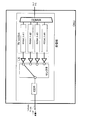
- FIG. 1 is a configuration diagram illustrating the wavelength tunable WDM / TDM-PON.
- an optical transmitter / receiver having wavelength variability is required for a subscriber unit or a station side unit.
- the wavelength tunable WDM / TDM-PON optical receiver demultiplexes wavelength-multiplexed N-wave signal light into one wave with a wavelength filter, and then outputs a signal with PD (Photodiode) corresponding to each wavelength.
- PD Photodiode
- a wavelength tunable receiver can be configured by photoelectrically converting light into an electrical signal and then selecting and receiving an electrical signal corresponding to the signal light having a desired wavelength with an electrical switch (for example, patents) Reference 1).
- the ONU selects the selector as shown in FIG. 2 even if it wants to adopt a method in which multiple wavelengths are allocated to a subscriber unit (ONU: Optical Network Unit). Therefore, the ONU cannot select a plurality of wavelengths at the same time. For this reason, only a single wavelength can be assigned to the ONU for structural reasons, but a plurality of wavelengths cannot be assigned at the same time. For this reason, the conventional WDM / TDM-PON system has a problem that different wavelengths are assigned for each service in the future, and it cannot cope with a system in which the same user tries to receive a plurality of services with the same ONU.
- An object of the present invention is to provide a subscriber unit capable of simultaneously receiving signals having a plurality of wavelengths and an optical receiving method thereof.
- the present invention includes two or more signal selection units for one ONU that receives optical signals of a plurality of wavelengths to which a plurality of services are allocated in downlink signal reception.
- the first aspect of the present invention includes a duplexer that demultiplexes input wavelength multiplexed light into a plurality of optical signals for each wavelength, and the plurality of lights that are demultiplexed by the duplexer.
- a plurality of optical receivers that respectively receive signals and convert them into electrical signals
- a plurality of limiting amplifiers that respectively amplify the plurality of electrical signals output from the plurality of optical receivers
- the plurality of limiting amplifiers A plurality of signal selection units for selecting a plurality of signals to be received from a plurality of amplified signals output from the subscriber unit.
- the second aspect of the present invention provides a demultiplexing procedure for demultiplexing input wavelength multiplexed light into a plurality of optical signals for each wavelength, and a plurality of the plurality of optical signals demultiplexed by the demultiplexing procedure.
- Optical receiving procedures for receiving the signals by the optical receivers and converting them to electrical signals by the plurality of optical signal units, and amplifying the plurality of electrical signals output from the plurality of optical signal units by a plurality of limiting amplifiers, respectively.
- a selection procedure in which a plurality of signal selection units select a plurality of signals to be received from a plurality of amplified signals output from the plurality of limiting amplifiers.
- the subscriber apparatus and the optical receiving method can select a plurality of signals having wavelengths corresponding to the service used in the signal selection unit, the subscriber apparatus and the optical receiving method can support a service of a system in which different services are allocated to different wavelengths. it can. Therefore, the present invention can provide a subscriber apparatus and an optical receiving method thereof that can simultaneously receive signals having a plurality of wavelengths.
- each of the signal selection units outputs one of the amplified signals output from the plurality of limiting amplifiers.
- a subscriber unit that selects exclusively as the signal to be received.
- a fourth aspect of the present invention is the subscriber device according to the first aspect, wherein at least one signal selection unit among the plurality of signal selection units is a plurality of the output from the plurality of limiting amplifiers.
- a subscriber apparatus according to the first, third, or fourth aspect, wherein the optical receiver outputs the electrical signal that is not selected by any of the signal selection units.
- a subscriber unit further includes a power management unit that stops a power source and a power source of the limiting amplifier that outputs the amplified signal that is not selected by any of the signal selection units. Since the subscriber unit can turn off the power of the circuit through which a signal other than the desired service passes, the power consumption can be reduced.
- the present invention can provide a subscriber apparatus capable of simultaneously receiving signals having a plurality of wavelengths and an optical receiving method thereof.
- FIG. 3 is a configuration diagram illustrating the ONU 301 of the present embodiment.
- ONU301 A demultiplexer 11 for demultiplexing the input wavelength multiplexed light for each wavelength; N optical receivers 12 (n is a natural number of 2 or more) for receiving the optical signal demultiplexed by the demultiplexer 11 for each wavelength; N LA13s for amplifying signals received by the optical receiver 12, respectively; M selectors 14 for exclusively selecting one of the signals amplified by the LA 13; Is provided.
- the demultiplexer 11 demultiplexes the wavelength multiplexed signal from the OLT for each wavelength.
- the wavelength multiplexed light is composed of optical signals of four wavelengths ( ⁇ d1, ⁇ d2, ⁇ d3, ⁇ d4), and the demultiplexer 11 demultiplexes the wavelength multiplexed light into four wavelengths.
- the optical receiver 12 converts the optical signal demultiplexed by the demultiplexer 11 into an electrical signal.
- the demultiplexed optical signals are four, four optical receivers (12-1 to 12-4) are arranged.
- the optical receiver 12 is a ROSA (Receiver Optical SubAssembly).
- the electric signal output from the optical receiver 12 is amplified by a limiting amplifier (LA) 13.
- LA 13 is arranged at the subsequent stage of each optical receiver 12.
- the four electrical signals amplified by each LA 13 are branched into two and input to the input ports of the selectors (14-a, 14-b), respectively.
- the selector 14 exclusively selects an electrical signal. For example, when the selector 14-a selects an electrical signal from the LA 13-1, the selector 14-b selects an electrical signal from other than the LA 13-1 (an electrical signal from the LA 13-2 in FIG. 3).
- the electrical signal selected by the selector 14 is output to the transfer unit 21 via the clock data recovery circuit (CDR) 15.
- CDR clock data recovery circuit
- the transfer unit 21 transfers an electrical signal to the user device.
- the transfer unit 21 may be a DBA control method gate or report used in the PON system, a LAN port for a wired user, or may transfer a signal to a user device by wireless transfer.
- the ONU 301 selects an electric signal to be selected by driving the selector 14 based on a control signal (service start, end) from the OLT.
- An administrator may set the selector 14 in advance.
- the ONU 301 can simultaneously receive and photoelectrically convert two or more wavelengths, and selects and receives the wavelength assigned to a desired service by the selector 14.
- the ONU 301 selects an electrical signal corresponding to a desired wavelength from the electrical signals after photoelectric conversion of each wavelength via the optical receiver 12 and LA 13 and inputs the selected electrical signal to the CDR 15.
- the output from each LA 13 is input to a plurality of signal selection units (10-a, 10-b) including a selector 14 and a CDR 15, so that a single ONU can simultaneously receive a plurality of wavelengths. It is possible to provide an ONU that can provide different wavelength services to different users.
- the signal selection units (10-a, 10-b) are mounted on the ONU.
- the present invention can be applied to a reception circuit incorporating an optical reception unit in which the function of the signal selection unit is mounted. Can be implemented.
- the ONU 301 includes two transfer units (21-a, 21-b), but the number of transfer units may be three or more. In this case, the electrical signal output from each LA 13 is branched to the number of transfer units.
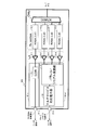
- FIG. 4 illustrates the ONU 302 of this embodiment.
- the ONU 302 stops the power supply of the optical receiver 12 that outputs an unselected signal by all the selectors 14 and the power supply of the LA 13 that amplifies an unselected signal by all the selectors 14 in the configuration of the ONU 301 described in FIG.
- the power management unit 16 is further provided.
- the ONU 302 is configured such that the power management unit 16 cuts off the power of a circuit having a wavelength that is not used by the user device.
- the power management unit 16 performs ON / OFF switching of the ROSA photodiode and the driving voltage of the LA.
- an ON / OFF switching function of the driving voltage / current of the electronic circuit (for example, the transfer unit 21) subsequent to the CDR 15 or the CDR may be added. This eliminates the need to use unnecessary electricity, so that it is possible to reduce unnecessary power consumption associated with the increase in the number of ports with the increased number of transfer units 21 and to operate the ONU with low power consumption.
- FIG. 5 is a diagram illustrating the ONU 303 of the present embodiment.
- the ONU 303 is an ONU variable wavelength receiver capable of simultaneously receiving and photoelectrically converting two or more wavelengths in the same manner as the ONU described with reference to FIGS. 3 and 4.
- the ONU 303 receives control signals (service start and end) from the OLT. Based on this, in order to receive the wavelength assigned to the service, the photodiodes assigned to the wavelength channel and the drive voltages such as LA and CDR are switched ON / OFF.
- the ONU 303 can provide a multi-service by receiving a plurality of services provided by using a plurality of wavelengths by the multi-service compatible electronic unit 18 by selecting and receiving a plurality of electrical signals.
- the wavelength ⁇ d1 is configured for data communication.
- the data signal of wavelength ⁇ d1 photoelectrically converted by the optical receiver 12-1 is output from the transfer unit 21a as a 10G electrical signal via the LA 13-1 and the CDR 15-1.
- the wavelengths ⁇ d2 to ⁇ d4 are multi-service signals.
- the ONU 303 includes a parallel / serial conversion unit 17 that supports multi-service reception, and a multi-service compatible electronic unit 18.
- the parallel / serial converter 17 performs parallel / serial conversion on the electrical signals output from the LA 13-2 to the LA 13-4.
- the multi-service electronic unit 18 extracts a frame including a desired service from the electrical signal that has been converted into a serial signal based on the identification information included in the frame and outputs the frame to the transfer unit 21-b.
- the identification information is information included in the header of the frame and information indicating the service.
- LLID Logical Link ID
- the ONU 303 can selectively receive any service from among the multi-services provided using a plurality of services.
- the selector included in the ONU in the first or second embodiment selects a signal based on a control signal from the OLT.
- the ONU 303 extracts information related to the service selected by the user from the multi-service compatible electronic unit 18 and outputs it to the transfer unit 21-b. Therefore, the ONU 303 of the present embodiment can output information related to an arbitrary service according to the user's selection regardless of the OLT control, and the convenience for the user can be improved.
- the parallel / serial conversion unit 17 is configured to selectively receive only one of the multi-services.
- a plurality of transfer units 21-b are provided so that a plurality of wavelengths, that is, It is also possible to select and receive a plurality of services.
- the ONU 303 can also cut off the power supply of the optical receiver 12 related to a wavelength that is not required. Since unnecessary services not subscribed to by the user are not subjected to photoelectric conversion, the confidentiality of the received signal can be enhanced for the user, and the illegal service reception preventing effect can also be obtained for the service provider.
- the ONU 303 can reduce power consumption by turning off drive voltages and currents of LA, CDR, multi-service electronic receivers, etc., of wavelengths that do not receive service.
- a subscriber unit comprising: a power management unit configured to stop the power supply of an element related to a wavelength unnecessary for reception in a lower-level user device among signals from the upper level.
- the present invention can also be applied to applications where it is essential to simultaneously receive signals having a plurality of wavelengths.
- 10-a, 10-b, 10-c, 10-d signal selection unit 11: demultiplexers 12, 12-1, 12-2, 12-3, 12-4: optical receivers 13, 13-1 , 13-2, 13-3, 13-4: LA 14, 14-a, 14-b: selector 15, 15-a, 15-b, 15-1: CDR 16: Power management unit 17: Parallel / serial conversion unit 18: Multi-service compatible electronic unit 21, 21-a, 21-b: Transfer unit 301 to 303: ONU
Landscapes
- Engineering & Computer Science (AREA)
- Computer Networks & Wireless Communication (AREA)
- Signal Processing (AREA)
- Physics & Mathematics (AREA)
- Electromagnetism (AREA)
- Computing Systems (AREA)
- Optical Communication System (AREA)
- Small-Scale Networks (AREA)
Abstract
Description
本願は、2015年5月21日に、日本に出願された特願2015-103713号に基づき優先権を主張し、その内容をここに援用する。
図3は、本実施形態のONU301を説明する構成図である。
ONU301は、
入力された波長多重光を波長毎に分波する分波器11と、
分波器11が分波した光信号を波長毎に受信するn個(nは2以上の自然数)の光受信器12と、
光受信器12が受信した信号をそれぞれ増幅するn個のLA13と、
LA13が増幅した信号のうちの一つを、排他的に選択するm個のセレクタ14と、
を備える。
本実施形態では、n=4、m=2である。
図4は、本実施形態のONU302を説明する。ONU302は、図3で説明したONU301の構成に、全てのセレクタ14で未選択の信号を出力する光受信器12の電源、及び全てのセレクタ14で未選択の信号を増幅するLA13の電源を停止する電源管理部16をさらに備える。
図5は、本実施形態のONU303を説明する図である。ONU303も図3や図4で説明したONUと同様に、2つ以上の波長を同時に受信・光電変換することが可能なONU波長可変受信機において、OLTからの制御信号(サービス開始、終了)に基づき、当該サービスに割り当てられた波長を受信するために、当該波長チャネルに割り当てられているフォトダイオード及びLA、CDRなどの駆動電圧のON/OFF切り替えを行う。
以下は、本実施形態のONUを説明したものである。
上位からの信号から波長を選択して下位へ転送する受信部有する加入者装置において、
ユーザ装置への転送部ごとに
上位からの複数波長の入力信号から前記複数の受光回路のうちの1つの受光回路からの電気信号を選択的に出力する電気スイッチと、前記電気スイッチの選択する前記1つの受光回路を変化させる制御回路と、を有する加入者装置。
上位からの信号のうち、下位のユーザ装置において受信不要な波長に関する素子の電源を停止する電源管理部とを有することを特徴とする加入者装置。
ONUが複数の波長を同時に受信することができるようにしたことで、ユーザの受けられるサービスを多彩化できるとともに、省電力を維持しつつ複数波長を同時に受信することができ、なおかつ通信内容の秘匿性及び不正受信防止効果を高めることが期待できる。
11:分波器
12、12-1、12-2、12-3、12-4:光受信器
13、13-1、13-2、13-3、13-4:LA
14、14-a、14-b:セレクタ
15、15-a、15-b、15-1:CDR
16:電源管理部
17:パラレル/シリアル変換部
18:マルチサービス対応電子部
21、21-a、21-b:転送部
301~303:ONU
Claims (5)
- 入力された波長多重光を波長毎に複数の光信号に分波する分波器と、
前記分波器により分波された前記複数の光信号をそれぞれ受信し、電気信号に変換する複数の光受信器と、
前記複数の光受信器から出力される複数の前記電気信号をそれぞれ増幅する複数のリミッティングアンプと、
前記複数のリミッティングアンプから出力される複数の増幅された信号から複数の受信すべき信号を選択する複数の信号選択部と、
を備える加入者装置。 - 前記信号選択部それぞれは、前記複数のリミッティングアンプから出力される複数の前記増幅された信号のうち一つを、前記受信すべき信号として排他的に選択する、
請求項1に記載の加入者装置。 - 複数の前記信号選択部のうち少なくとも1つの信号選択部は、前記複数のリミッティングアンプから出力される複数の前記増幅された信号から、所望のサービスを含む前記増幅された信号を前記受信すべき信号として選択する、
請求項1に記載の加入者装置。 - 前記信号選択部のいずれにも選択されていない前記電気信号を出力する前記光受信器の電源と、前記信号選択部のいずれにも選択されていない前記増幅された信号を出力する前記リミッティングアンプの電源とを停止する電源管理部をさらに備える、
請求項1から請求項3のいずれか一項に記載の加入者装置。 - 入力された波長多重光を波長毎に複数の光信号に分波する分波手順と、
前記分波手順で分波された前記複数の光信号を複数の光受信器でそれぞれ受信し、前記複数の光信号器で電気信号に変換する光受信手順と、
前記複数の光信号器から出力される複数の前記電気信号を複数のリミッティングアンプでそれぞれ増幅する増幅手順と、
前記複数のリミッティングアンプから出力される複数の増幅された信号から複数の受信すべき信号を複数の信号選択部で選択する選択手順と、
を行う光受信方法。
Priority Applications (3)
| Application Number | Priority Date | Filing Date | Title |
|---|---|---|---|
| JP2017519400A JP6438578B2 (ja) | 2015-05-21 | 2016-05-19 | 加入者装置 |
| US15/573,706 US10250331B2 (en) | 2015-05-21 | 2016-05-19 | Subscriber device and light receiving method |
| CN201680028739.0A CN107615685B (zh) | 2015-05-21 | 2016-05-19 | 用户装置以及光接收方法 |
Applications Claiming Priority (2)
| Application Number | Priority Date | Filing Date | Title |
|---|---|---|---|
| JP2015-103713 | 2015-05-21 | ||
| JP2015103713 | 2015-05-21 |
Publications (1)
| Publication Number | Publication Date |
|---|---|
| WO2016186176A1 true WO2016186176A1 (ja) | 2016-11-24 |
Family
ID=57320368
Family Applications (1)
| Application Number | Title | Priority Date | Filing Date |
|---|---|---|---|
| PCT/JP2016/064919 Ceased WO2016186176A1 (ja) | 2015-05-21 | 2016-05-19 | 加入者装置及び光受信方法 |
Country Status (4)
| Country | Link |
|---|---|
| US (1) | US10250331B2 (ja) |
| JP (1) | JP6438578B2 (ja) |
| CN (1) | CN107615685B (ja) |
| WO (1) | WO2016186176A1 (ja) |
Cited By (1)
| Publication number | Priority date | Publication date | Assignee | Title |
|---|---|---|---|---|
| JPWO2021250756A1 (ja) * | 2020-06-08 | 2021-12-16 |
Families Citing this family (2)
| Publication number | Priority date | Publication date | Assignee | Title |
|---|---|---|---|---|
| JP7328596B2 (ja) * | 2020-03-02 | 2023-08-17 | 日本電信電話株式会社 | 波長多重通信システム及び波長多重通信方法 |
| US20250373354A1 (en) * | 2024-05-31 | 2025-12-04 | At&T Intellectual Property I, L.P. | Colorless optical transmission for wavelength division multiplexing |
Citations (4)
| Publication number | Priority date | Publication date | Assignee | Title |
|---|---|---|---|---|
| JP2006165953A (ja) * | 2004-12-07 | 2006-06-22 | Oki Electric Ind Co Ltd | 光通信システム |
| JP2008147913A (ja) * | 2006-12-08 | 2008-06-26 | Hitachi Communication Technologies Ltd | パッシブ光ネットワークシステム、光終端装置及び光ネットワークユニット |
| JP2008277962A (ja) * | 2007-04-26 | 2008-11-13 | Matsushita Electric Ind Co Ltd | 光受信装置 |
| JP2014138291A (ja) * | 2013-01-17 | 2014-07-28 | Nippon Telegr & Teleph Corp <Ntt> | 波長可変受信器及び制御方法 |
Family Cites Families (8)
| Publication number | Priority date | Publication date | Assignee | Title |
|---|---|---|---|---|
| US6941079B1 (en) * | 2001-05-24 | 2005-09-06 | Cisco Technology, Inc. | Optical demultiplexer with multi-channel power control and tilt compensation |
| US7050719B2 (en) * | 2002-08-19 | 2006-05-23 | Lemoff Brian E | Wavelength division multiplexing receiver for wavelength tracking |
| PT1830491E (pt) * | 2004-12-01 | 2013-02-05 | Zte Corp | Dispositivo receptor por via óptica adaptativa e o seu método |
| JP5667395B2 (ja) * | 2010-01-25 | 2015-02-12 | 富士通株式会社 | 光受信器 |
| KR20120128847A (ko) * | 2011-05-18 | 2012-11-28 | 한국전자통신연구원 | 레인별로 전원을 제어하기 위한 광 트랜시버 모듈 |
| CN102710326B (zh) * | 2012-06-04 | 2015-03-25 | 上海大学 | 具备远端节点保护功能的波分复用无源光网络系统及其实现方法 |
| CN103152657B (zh) * | 2013-03-21 | 2015-05-27 | 上海交通大学 | 基于共享发射机节能方案的wdm-ofdm-pon系统 |
| CN103916195B (zh) * | 2014-04-14 | 2017-02-08 | 四川华拓光通信股份有限公司 | 一种多波长光接收装置 |
-
2016
- 2016-05-19 US US15/573,706 patent/US10250331B2/en active Active
- 2016-05-19 WO PCT/JP2016/064919 patent/WO2016186176A1/ja not_active Ceased
- 2016-05-19 CN CN201680028739.0A patent/CN107615685B/zh active Active
- 2016-05-19 JP JP2017519400A patent/JP6438578B2/ja active Active
Patent Citations (4)
| Publication number | Priority date | Publication date | Assignee | Title |
|---|---|---|---|---|
| JP2006165953A (ja) * | 2004-12-07 | 2006-06-22 | Oki Electric Ind Co Ltd | 光通信システム |
| JP2008147913A (ja) * | 2006-12-08 | 2008-06-26 | Hitachi Communication Technologies Ltd | パッシブ光ネットワークシステム、光終端装置及び光ネットワークユニット |
| JP2008277962A (ja) * | 2007-04-26 | 2008-11-13 | Matsushita Electric Ind Co Ltd | 光受信装置 |
| JP2014138291A (ja) * | 2013-01-17 | 2014-07-28 | Nippon Telegr & Teleph Corp <Ntt> | 波長可変受信器及び制御方法 |
Cited By (2)
| Publication number | Priority date | Publication date | Assignee | Title |
|---|---|---|---|---|
| JPWO2021250756A1 (ja) * | 2020-06-08 | 2021-12-16 | ||
| US12362831B2 (en) | 2020-06-08 | 2025-07-15 | Nippon Telegraph And Telephone Corporation | Optical main signal processing node apparatus and control method of optical main signal processing node apparatus |
Also Published As
| Publication number | Publication date |
|---|---|
| CN107615685A (zh) | 2018-01-19 |
| CN107615685B (zh) | 2020-06-19 |
| US10250331B2 (en) | 2019-04-02 |
| US20180145758A1 (en) | 2018-05-24 |
| JP6438578B2 (ja) | 2018-12-12 |
| JPWO2016186176A1 (ja) | 2017-11-30 |
Similar Documents
| Publication | Publication Date | Title |
|---|---|---|
| US8873963B2 (en) | Apparatus and methods for generating and receiving optical signals at substantially 100Gb/s and beyond | |
| US8442401B2 (en) | Method and device for fiber access physical layer unbundling using multiple uplink cards | |
| US20110286746A1 (en) | Transponder Aggregator Without Wavelength Selector for Colorless and Directionless Multi-Degree ROADM Node | |
| US20120106963A1 (en) | System, Method And Relevant Device For Signal Transmission | |
| EP2464039B1 (en) | Transponder and related network node for an optical transmission network | |
| JP4820880B2 (ja) | 局側終端装置 | |
| CN101420285A (zh) | 光线路终端、远端节点单元、减少光源数量的方法及系统 | |
| CN101577842A (zh) | 一种光通信系统、装置和方法 | |
| US9065589B2 (en) | Apparatus and method for operating a wavelength division multiplexing access network | |
| JP5334878B2 (ja) | 光通信システム、局側装置、加入者側装置、及び光通信方法 | |
| JP5821644B2 (ja) | 光信号中継装置、及び光通信ネットワークシステム | |
| JP6438578B2 (ja) | 加入者装置 | |
| CN113382316B (zh) | 光线路终端、光网络单元及光通信系统 | |
| KR20100000740A (ko) | 광대역 무선 서비스를 위한 광 백홀 네트워크 | |
| JPWO2009011053A1 (ja) | ポイント−マルチポイント光通信システム | |
| US20150229429A1 (en) | Multiplexer with Non-Interleaved Channel Plan | |
| JP4909547B2 (ja) | 光スイッチ装置、光アクセスネットワーク、そのシステムおよび光波長多重伝送方法 | |
| JP2019512924A (ja) | ポイントツーマルチポイントネットワーク用のコスト最適化されたアグリゲータベースの通信トポロジ | |
| JP5990469B2 (ja) | 波長可変受信器及び制御方法 | |
| JP5663629B2 (ja) | 光増幅システム | |
| Li et al. | Demonstration of hybrid optical ring network combining multi-wavelength OPS and OCS | |
| CN103974150A (zh) | 一种光同轴单元及光电混合系统中的信号传输方法 | |
| Aleksi? | Optically Transparent Core Nodes for Burst-Switched Networks with Channel Bonding | |
| Shinada et al. | Demonstration of multi-hop optical packet switching and transmission using SOA-based optical packet switches | |
| JP2017053908A (ja) | 波長選択モジュール及び光スイッチ制御方法 |
Legal Events
| Date | Code | Title | Description |
|---|---|---|---|
| 121 | Ep: the epo has been informed by wipo that ep was designated in this application |
Ref document number: 16796569 Country of ref document: EP Kind code of ref document: A1 |
|
| ENP | Entry into the national phase |
Ref document number: 2017519400 Country of ref document: JP Kind code of ref document: A |
|
| WWE | Wipo information: entry into national phase |
Ref document number: 15573706 Country of ref document: US |
|
| NENP | Non-entry into the national phase |
Ref country code: DE |
|
| 122 | Ep: pct application non-entry in european phase |
Ref document number: 16796569 Country of ref document: EP Kind code of ref document: A1 |