WO2016186077A1 - 端末装置 - Google Patents
端末装置 Download PDFInfo
- Publication number
- WO2016186077A1 WO2016186077A1 PCT/JP2016/064479 JP2016064479W WO2016186077A1 WO 2016186077 A1 WO2016186077 A1 WO 2016186077A1 JP 2016064479 W JP2016064479 W JP 2016064479W WO 2016186077 A1 WO2016186077 A1 WO 2016186077A1
- Authority
- WO
- WIPO (PCT)
- Prior art keywords
- subframe
- csi
- cell
- terminal device
- downlink
- Prior art date
Links
Images


Classifications
-
- H—ELECTRICITY
- H04—ELECTRIC COMMUNICATION TECHNIQUE
- H04L—TRANSMISSION OF DIGITAL INFORMATION, e.g. TELEGRAPHIC COMMUNICATION
- H04L25/00—Baseband systems
- H04L25/02—Details ; arrangements for supplying electrical power along data transmission lines
- H04L25/0202—Channel estimation
- H04L25/0224—Channel estimation using sounding signals
- H04L25/0226—Channel estimation using sounding signals sounding signals per se
-
- H—ELECTRICITY
- H04—ELECTRIC COMMUNICATION TECHNIQUE
- H04J—MULTIPLEX COMMUNICATION
- H04J11/00—Orthogonal multiplex systems, e.g. using WALSH codes
- H04J11/0069—Cell search, i.e. determining cell identity [cell-ID]
- H04J11/0079—Acquisition of downlink reference signals, e.g. detection of cell-ID
-
- H—ELECTRICITY
- H04—ELECTRIC COMMUNICATION TECHNIQUE
- H04L—TRANSMISSION OF DIGITAL INFORMATION, e.g. TELEGRAPHIC COMMUNICATION
- H04L27/00—Modulated-carrier systems
- H04L27/0006—Assessment of spectral gaps suitable for allocating digitally modulated signals, e.g. for carrier allocation in cognitive radio
-
- H—ELECTRICITY
- H04—ELECTRIC COMMUNICATION TECHNIQUE
- H04L—TRANSMISSION OF DIGITAL INFORMATION, e.g. TELEGRAPHIC COMMUNICATION
- H04L5/00—Arrangements affording multiple use of the transmission path
- H04L5/0001—Arrangements for dividing the transmission path
- H04L5/0003—Two-dimensional division
- H04L5/0005—Time-frequency
- H04L5/0007—Time-frequency the frequencies being orthogonal, e.g. OFDM(A), DMT
- H04L5/001—Time-frequency the frequencies being orthogonal, e.g. OFDM(A), DMT the frequencies being arranged in component carriers
-
- H—ELECTRICITY
- H04—ELECTRIC COMMUNICATION TECHNIQUE
- H04L—TRANSMISSION OF DIGITAL INFORMATION, e.g. TELEGRAPHIC COMMUNICATION
- H04L5/00—Arrangements affording multiple use of the transmission path
- H04L5/003—Arrangements for allocating sub-channels of the transmission path
- H04L5/0053—Allocation of signaling, i.e. of overhead other than pilot signals
- H04L5/0057—Physical resource allocation for CQI
-
- H—ELECTRICITY
- H04—ELECTRIC COMMUNICATION TECHNIQUE
- H04W—WIRELESS COMMUNICATION NETWORKS
- H04W16/00—Network planning, e.g. coverage or traffic planning tools; Network deployment, e.g. resource partitioning or cells structures
- H04W16/14—Spectrum sharing arrangements between different networks
-
- H—ELECTRICITY
- H04—ELECTRIC COMMUNICATION TECHNIQUE
- H04W—WIRELESS COMMUNICATION NETWORKS
- H04W72/00—Local resource management
- H04W72/04—Wireless resource allocation
-
- H—ELECTRICITY
- H04—ELECTRIC COMMUNICATION TECHNIQUE
- H04W—WIRELESS COMMUNICATION NETWORKS
- H04W72/00—Local resource management
- H04W72/20—Control channels or signalling for resource management
- H04W72/23—Control channels or signalling for resource management in the downlink direction of a wireless link, i.e. towards a terminal
-
- H—ELECTRICITY
- H04—ELECTRIC COMMUNICATION TECHNIQUE
- H04W—WIRELESS COMMUNICATION NETWORKS
- H04W72/00—Local resource management
- H04W72/50—Allocation or scheduling criteria for wireless resources
- H04W72/54—Allocation or scheduling criteria for wireless resources based on quality criteria
-
- H—ELECTRICITY
- H04—ELECTRIC COMMUNICATION TECHNIQUE
- H04J—MULTIPLEX COMMUNICATION
- H04J2211/00—Orthogonal indexing scheme relating to orthogonal multiplex systems
- H04J2211/003—Orthogonal indexing scheme relating to orthogonal multiplex systems within particular systems or standards
- H04J2211/005—Long term evolution [LTE]
-
- H—ELECTRICITY
- H04—ELECTRIC COMMUNICATION TECHNIQUE
- H04L—TRANSMISSION OF DIGITAL INFORMATION, e.g. TELEGRAPHIC COMMUNICATION
- H04L5/00—Arrangements affording multiple use of the transmission path
- H04L5/003—Arrangements for allocating sub-channels of the transmission path
- H04L5/0053—Allocation of signaling, i.e. of overhead other than pilot signals
-
- H—ELECTRICITY
- H04—ELECTRIC COMMUNICATION TECHNIQUE
- H04L—TRANSMISSION OF DIGITAL INFORMATION, e.g. TELEGRAPHIC COMMUNICATION
- H04L5/00—Arrangements affording multiple use of the transmission path
- H04L5/14—Two-way operation using the same type of signal, i.e. duplex
- H04L5/1469—Two-way operation using the same type of signal, i.e. duplex using time-sharing
Definitions
- Embodiments described herein relate generally to a terminal device, a base station device, a communication method, and an integrated circuit technology that realize efficient communication.
- Eol realized high-speed communication by adopting OFDM (Orthogonal Frequency-Division Multiplexing) communication method and flexible scheduling in predetermined frequency and time units called resource blocks.
- OFDM Orthogonal Frequency-Division Multiplexing
- UTRA Universal Terrestrial Radio Access
- E-UTRA realizes higher-speed data transmission and has upward compatibility with E-UTRA.
- a base station apparatus is a communication system on the premise of a network having substantially the same cell configuration (cell size).
- base stations (cells) having different configurations are in the same area.
- a communication system based on a mixed network (a heterogeneous wireless network, a heterogeneous network) has been studied.
- E-UTRA is also referred to as LTE (Long TermEEvolution), and Advanced E-UTRA is also referred to as LTE-Advanced.
- LTE can also be a generic term including LTE-Advanced.
- the terminal device includes a macro cell and a small cell.
- Carrier aggregation (CA) technology and dual connectivity (DC) technology for simultaneous communication and communication are defined (Non-patent Document 1).
- Non-Patent Document 2 discusses license-assisted access (LAA).
- LAA for example, an unassigned frequency band (Unlicensed spectrum) used by a wireless LAN (Local Area Network) is used as LTE.
- an unassigned frequency band is set as a secondary cell (secondary component carrier).
- the secondary cell used as the LAA is assisted with respect to connection, communication and / or setting by a primary cell (primary component carrier) set in an assigned frequency band (Licensed spectrum).
- LAA expands the frequency band that can be used in LTE, thereby enabling broadband transmission.
- LAA is also used in a shared frequency band (shared spectrum) shared between predetermined operators.
- LAA when an unassigned frequency band or a shared frequency band is used, the frequency band is shared with other systems and / or other operators.
- LTE is designed on the assumption that it is used in an allocated frequency band or a non-shared frequency band. Therefore, the conventional LTE cannot be used in the unassigned frequency band or the shared frequency band.
- the present invention has been made in view of the above points, and an object of the present invention is to provide a terminal device, a base station device, and a communication method capable of efficiently controlling a cell using an unassigned frequency band or a shared frequency band. Is to provide.
- a terminal apparatus is a terminal apparatus, and includes a measurement unit that measures channel state information (CSI) based on an effective downlink subframe based on a serving cell, and satisfies the condition.
- the subframe is considered to be the valid downlink subframe, and the condition is that a configured CSI reference signal (CSI-RS) resource associated with the channel state information process is present in the subframe.
- the serving cell is a License Assisted Access (LAA) secondary cell.
- LAA License Assisted Access
- the terminal device is the terminal device described above, wherein the condition is that the subframe is set as a downlink subframe or a special subframe, and the subframe is: MBSFN (Multimedia Broadcast multicast service Single Frequency Network) that is not a subframe and that the subframe is not included in the set measurement interval range.
- the subframe is an element of a CSI subframe set linked to the periodic CSI report, and in the aperiodic CSI report for a CSI process, the condition is that the subframe is an uplink Correspondence in the downlink control information (DCI) format It is an element of CSI subframe set linked to the sub-frame with the CSI request that includes.
- DCI downlink control information
- a terminal apparatus is the terminal apparatus described above, wherein the subframe includes the configured CSI reference signal resource associated with the channel state information process. Otherwise, it is not considered to be a valid downlink subframe.
- the subframe is considered to be the effective downlink subframe based on a field of downlink control information, and the field sets an OFDM (Orthogonal-Frequency-Division-Multiplexing) symbol setting of the subframe.
- the OFDM symbol is used for transmission of at least one of a physical downlink channel and a physical downlink signal.
- a terminal apparatus is the terminal apparatus described above, wherein the subframe includes the field of the downlink control information, and at least one OFDM symbol of the subframe includes the transmission. If it is not used, it is not considered to be a valid downlink subframe.
- a terminal device is the above-described terminal device, wherein the subframe uses the field of the downlink control information, and all OFDM symbols of the subframe use the transmission. If so, it is considered to be the valid downlink subframe.
- a terminal apparatus is the above-described terminal apparatus, and includes physical downlink with the downlink control information including CRC (Cyclic Redundancy Check) scrambled by RNTI (Radio Network Temporary Identifier).
- CRC Cyclic Redundancy Check
- RNTI Radio Network Temporary Identifier
- a link control channel (PDCCH) is detected.
- transmission efficiency can be improved in a wireless communication system in which a base station device and a terminal device communicate.
- a first embodiment of the present invention will be described below.
- a base station apparatus base station, Node B, eNB (eNodeB)
- a terminal apparatus terminal, mobile station, user apparatus, UE (User equipment)
- a communication system cellular system
- a channel means a medium used for signal transmission
- a physical channel means a physical medium used for signal transmission.
- a physical channel can be used synonymously with a signal.
- the physical channel may be added in the future, or the structure and format of the physical channel may be changed or added in EUTRA and Advanced EUTRA, but even if changed or added, the description of the present embodiment is not affected.
- Radio frames In EUTRA and Advanced EUTRA, scheduling of physical channels or physical signals is managed using radio frames.
- One radio frame is 10 ms, and one radio frame is composed of 10 subframes. Further, one subframe is composed of two slots (that is, one subframe is 1 ms, and one slot is 0.5 ms).
- resource blocks are used as a minimum scheduling unit in which physical channels are allocated.
- a resource block is defined by a constant frequency region composed of a set of a plurality of subcarriers (for example, 12 subcarriers) and a region composed of a constant transmission time interval (1 slot) on the frequency axis.
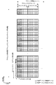
- FIG. 1 is a diagram illustrating an example of a downlink radio frame configuration according to the present embodiment.
- An OFDM access scheme is used for the downlink.
- a PDCCH, an EPDCCH, a physical downlink shared channel (PDSCH), a physical downlink shared channel, and the like are allocated.
- the downlink radio frame is composed of a downlink resource block (RB) pair.
- RB bandwidth predetermined frequency band
- One downlink RB pair is composed of two downlink RBs (RB bandwidth ⁇ slot) that are continuous in the time domain.
- One downlink RB is composed of 12 subcarriers in the frequency domain.
- the time domain is composed of 7 OFDM symbols when a normal cyclic prefix (CP) is added, and 6 OFDM symbols when a cyclic prefix longer than normal is added. Is done.
- a region defined by one subcarrier in the frequency domain and one OFDM symbol in the time domain is referred to as a resource element (RE).
- the physical downlink control channel is a physical channel through which downlink control information such as a terminal device identifier, physical downlink shared channel scheduling information, physical uplink shared channel scheduling information, modulation scheme, coding rate, and retransmission parameter is transmitted. It is.
- the downlink sub-frame in one element carrier (CC; Component Carrier) is described here, a downlink sub-frame is prescribed
- a synchronization signal (Synchronization Signals), a physical broadcast information channel, and a downlink reference signal (RS: Reference Signal, downlink reference signal) may be arranged in the downlink subframe.
- CSI Channel State Information
- CRS Cell-specific RS
- CSI channel state information
- URS terminal specific reference signal
- DMRS Demodulation reference signals
- positioned may be sufficient.
- a part of CRS transmission ports for example, transmission port 0 only
- signals similar to those corresponding to all transmission ports (referred to as extended synchronization signals) can be inserted.
- a terminal-specific reference signal transmitted through the same transmission port as a part of PDSCH is also referred to as a terminal-specific reference signal or DMRS associated with the PDSCH.
- the demodulation reference signal transmitted at the same transmission port as the EPDCCH is also referred to as DMRS associated with the EPDCCH.
- the downlink subframe mainly includes zero power CSI-RS (ZP CSI-RS) used mainly for rate matching of PDSCH transmitted at the same time, and mainly channel state information.
- ZP CSI-RS zero power CSI-RS
- CSI-IM CSI interference management
- Zero power CSI-RS and CSI-IM may be arranged in resource elements where non-zero power CSI-RS can be arranged.
- the CSI-IM may be set to overlap the zero power CSI-RS.
- a detection signal may be arranged in the downlink subframe.
- a DS DS Occlusion
- a time period DS period
- the predetermined number is 1 to 5 in FDD (Frame structure type ⁇ 1) and 2 to 5 in TDD (Frame structure type 2).
- the predetermined number is set by RRC signaling.
- the DS period or its setting is also called DMTC (Discovery signals measurement timing configuration).
- the terminal assumes that the DS is transmitted (mapped and generated) for each subframe set by the parameter dmtc-Periodicity set by RRC signaling.
- the terminal assumes the presence of a DS configured to include the following signals.
- Non-zero power CSI-RS in zero or more subframes in the DS period.
- the non-zero power CSI-RS is set by RRS signaling.
- the terminal performs measurement based on the set DS.
- the measurement is performed using CRS in DS or non-zero power CSI-RS in DS.
- a plurality of non-zero power CSI-RSs can be set.
- FIG. 2 is a diagram illustrating an example of an uplink radio frame configuration according to the present embodiment.
- the SC-FDMA scheme is used for the uplink.
- a physical uplink shared channel Physical Uplink Shared Channel (PUSCH), PUCCH, and the like are allocated.
- an uplink reference signal (uplink reference signal) is assigned to a part of PUSCH or PUCCH.
- One uplink RB pair is composed of two uplink RBs (RB bandwidth ⁇ slot) that are continuous in the time domain.
- One uplink RB is composed of 12 subcarriers in the frequency domain. In the time domain, it is composed of seven SC-FDMA symbols when a normal cyclic prefix is added and six SC-FDMA symbols when a longer cyclic prefix is added.
- an uplink subframe in one CC is described, an uplink subframe is defined for each CC.
- the synchronization signal is composed of three kinds of primary synchronization signals and a secondary synchronization signal composed of 31 kinds of codes arranged alternately in the frequency domain.
- 504 cell identifiers (physical cell identity (PCI)) for identifying a station device and frame timing for radio synchronization are shown.
- the terminal device specifies the physical cell ID of the synchronization signal received by the cell search.
- the physical broadcast information channel (PBCH; Physical Broadcast Channel) is transmitted for the purpose of notifying (setting) control parameters (broadcast information (system information); System information) commonly used in terminal devices in the cell.
- Radio resources for transmitting broadcast information on the physical downlink control channel are notified to terminal devices in the cell, and broadcast information not notified on the physical broadcast information channel is transmitted by the physical downlink shared channel in the notified radio resources.
- a layer 3 message (system information) for notifying broadcast information is transmitted.
- CGI cell global identifier
- TAI tracking area identifier
- Common radio resource setting information As broadcast information, a cell global identifier (CGI) indicating a cell-specific identifier, a tracking area identifier (TAI) for managing a standby area by paging, tracking access identifier (random timing setting information, etc.), Common radio resource setting information, neighboring cell information, uplink access restriction information, etc. in the cell are notified.
- CGI cell global identifier
- TAI tracking area identifier
- Downlink reference signals are classified into multiple types according to their use.
- a cell-specific reference signal is a pilot signal transmitted at a predetermined power for each cell, and is a downlink reference signal that is periodically repeated in the frequency domain and the time domain based on a predetermined rule. It is.
- the terminal device measures the reception quality for each cell by receiving the cell-specific RS.
- the terminal apparatus also uses the cell-specific RS as a reference signal for demodulating the physical downlink control channel or the physical downlink shared channel transmitted simultaneously with the cell-specific RS.
- a sequence used for the cell-specific RS a sequence that can be identified for each cell is used.
- the downlink reference signal is also used for estimation of downlink propagation path fluctuation.
- a downlink reference signal used for estimation of propagation path fluctuation is referred to as a channel state information reference signal (CSI-RS).
- the downlink reference signal set individually for the terminal device is referred to as UE specific reference signals (URS), Demodulation Reference Signal (DMRS) or Dedicated RS (DRS), or an extended physical downlink control channel, or Referenced for channel propagation path compensation processing when demodulating a physical downlink shared channel.
- URS UE specific reference signals
- DMRS Demodulation Reference Signal
- DRS Dedicated RS
- a physical downlink control channel (PDCCH; Physical Downlink Control Channel) is transmitted in several OFDM symbols (for example, 1 to 4 OFDM symbols) from the top of each subframe.
- An extended physical downlink control channel (EPDCCH; Enhanced Physical Downlink Control Channel) is a physical downlink control channel arranged in an OFDM symbol in which the physical downlink shared channel PDSCH is arranged.
- the PDCCH or EPDCCH is used for the purpose of notifying the terminal device of radio resource allocation information according to the scheduling of the base station device and information for instructing an adjustment amount of increase / decrease of transmission power.
- a physical downlink control channel (PDCCH) it means both physical channels of PDCCH and EPDCCH unless otherwise specified.
- the terminal device monitors (monitors) the physical downlink control channel addressed to itself before transmitting / receiving the downlink data and the layer 2 message and the layer 3 message (paging, handover command, etc.) as upper layer control information.
- the physical downlink control channel addressed to its own device it is necessary to acquire radio resource allocation information called uplink grant at the time of transmission and downlink grant (downlink assignment) at the time of reception from the physical downlink control channel. is there.
- the physical downlink control channel may be configured to be transmitted in the area of the resource block that is assigned individually (dedicated) from the base station apparatus to the terminal apparatus, in addition to being transmitted by the OFDM symbol described above. Is possible.
- the physical uplink control channel (PUCCH; Physical Uplink Control Channel) is a downlink data reception confirmation response (HARQ-ACK; Hybrid Automatic Repeat reQuestNackingAcknowledgementACK / NACK); It is used to perform Acknowledgment), downlink propagation path (channel state) information (CSI; Channel State Information), and uplink radio resource allocation request (radio resource request, scheduling request (SR)).
- PUCCH Physical Uplink Control Channel
- HARQ-ACK Hybrid Automatic Repeat reQuestNackingAcknowledgementACK / NACK
- CSI downlink propagation path
- CSI Channel State Information
- SR uplink radio resource allocation request
- the CSI is a reception quality index (CQI: Channel Quality Indicator), precoding matrix index (PMI: Precoding Matrix Indicator), precoding type index (PTI: Precoding Type Indicator), and rank index (rank index) corresponding to the CSI. And can be used to specify (represent) a suitable modulation scheme and coding rate, a suitable precoding matrix, a suitable PMI type, and a suitable rank, respectively. Each Indicator may be written as Indication. Also, for CQI and PMI, wideband CQI and PMI assuming transmission using all resource blocks in one cell and some continuous resource blocks (subbands) in one cell were used. It is classified into subband CQI and PMI assuming transmission. In addition to the normal type of PMI that represents one suitable precoding matrix with one PMI, the PMI represents one suitable precoding matrix using two types of PMIs, the first PMI and the second PMI. There is a type of PMI.
- CQI Channel Quality Indicator
- PMI Precoding Mat
- the terminal apparatus 1 occupies a group of downlink physical resource blocks, and the error probability of one PDSCH transport determined by a combination of a modulation scheme and a transport block size corresponding to the CQI index has a predetermined value (for example, , 0.1), the CQI index that satisfies the condition is not reported.
- a predetermined value for example, , 0.1
- CSI reference resource the downlink physical resource block used for the calculation of CQI, PMI and / or RI.
- the terminal device 1 reports the CSI to the base station device 2.
- the CSI report includes a periodic CSI report and an aperiodic CSI report.
- periodic CSI reporting the terminal device 1 reports CSI at the timing set in the higher layer.
- aperiodic CSI report the terminal device 1 reports the CSI at a timing based on the information of the CSI request included in the received uplink DCI format (uplink grant) or random access response grant.
- the terminal device 1 reports CQI and / or PMI and / or RI. Note that the terminal apparatus 1 may not report PMI and / or RI depending on the setting of the upper layer.
- the settings of the upper layer are, for example, a transmission mode, a feedback mode, a report type, and a parameter indicating whether to report PMI / RI.
- one or a plurality of CSI processes may be set for one serving cell.
- the CSI process is set in association with the CSI report.
- One CSI process is associated with one CSI-RS resource and one CSI-IM resource.
- the physical downlink shared channel (PDSCH; Physical Downlink Shared Channel), in addition to downlink data, provides response to random access (random access response, RAR), paging, and broadcast information (system information) that is not notified by the physical broadcast information channel. It is also used to notify the terminal device as a layer 3 message.
- the radio resource allocation information of the physical downlink shared channel is indicated by the physical downlink control channel.
- the physical downlink shared channel is transmitted after being arranged in an OFDM symbol other than the OFDM symbol through which the physical downlink control channel is transmitted. That is, the physical downlink shared channel and the physical downlink control channel are time division multiplexed within one subframe.
- the physical uplink shared channel (PUSCH; Physical Uplink Shared Channel) mainly transmits uplink data and uplink control information, and can also include uplink control information such as CSI and ACK / NACK. In addition to uplink data, it is also used to notify the base station apparatus of layer 2 messages and layer 3 messages, which are higher layer control information. Similarly to the downlink, the radio resource allocation information of the physical uplink shared channel is indicated by the physical downlink control channel.
- the uplink reference signal (uplink reference signal; Uplink Reference Signal, uplink pilot signal, also referred to as uplink pilot channel) is transmitted from the base station apparatus to the physical uplink control channel PUCCH and / or the physical uplink shared channel PUSCH.
- demodulation reference signal (DMRS) used for demodulation and sounding reference signal (SRS) used mainly by base station equipment to estimate uplink channel conditions It is.
- the sounding reference signal includes a periodic sounding reference signal (Periodic SRS) transmitted periodically and an aperiodic sounding reference signal (Aperiodic SRS) transmitted when instructed by the base station apparatus. .
- a physical random access channel is a channel used to notify (set) a preamble sequence and has a guard time.
- the preamble sequence is configured to notify information to the base station apparatus by a plurality of sequences. For example, when 64 types of sequences are prepared, 6-bit information can be indicated to the base station apparatus.
- the physical random access channel is used as an access means for the terminal device to the base station device.
- the terminal apparatus transmits transmission timing adjustment information (timing required for uplink radio resource request when the physical uplink control channel is not set for the SR, or for matching the uplink transmission timing with the reception timing window of the base station apparatus.
- the physical random access channel is used to request the base station apparatus for an advance (also called a timing advance (TA) command). Also, the base station apparatus can request the terminal apparatus to start a random access procedure using the physical downlink control channel.
- TA timing advance
- the random access response is response information from the base station apparatus with respect to the random access of the terminal apparatus.
- the random access response is included in the PDSCH scheduled by the control information of the PDCCH having the CRC scrambled by the RA-RNTI, and is transmitted from the base station apparatus.
- the random access response includes transmission timing adjustment information, an uplink grant (the uplink grant included in the random access response is also referred to as a random access response grant), and Temporary C-RNTI information that is a temporary terminal device identifier. include.
- the layer 3 message is a message handled in the protocol of the control plane (CP (Control-plane, C-Plane)) exchanged between the terminal device and the RRC (Radio Resource Control) layer of the base station device, and RRC signaling or RRC Can be used interchangeably with message.
- CP Control-plane, C-Plane
- RRC Radio Resource Control
- a protocol that handles user data (uplink data and downlink data) with respect to the control plane is referred to as a user plane (UP (User-plane, U-Plane)).
- UP User-plane, U-Plane
- the transport block that is transmission data in the physical layer includes a C-Plane message and U-Plane data in the upper layer. Detailed descriptions of other physical channels are omitted.
- the communicable range (communication area) of each frequency controlled by the base station apparatus is regarded as a cell.
- the communication area covered by the base station apparatus may have a different width and a different shape for each frequency.
- the area to cover may differ for every frequency.
- a wireless network in which cells having different types of base station apparatuses and different cell radii are mixed in the same frequency and / or different frequency areas to form one communication system is referred to as a heterogeneous network. .
- the terminal device operates by regarding the inside of the cell as a communication area.
- a terminal device moves from one cell to another cell, it moves to another appropriate cell by a cell reselection procedure during non-wireless connection (during communication) and by a handover procedure during wireless connection (during communication).
- An appropriate cell is a cell that is generally determined that access by a terminal device is not prohibited based on information specified by a base station device, and the downlink reception quality satisfies a predetermined condition. Indicates the cell to be used.
- the terminal device and the base station device aggregate (aggregate) frequencies (component carriers or frequency bands) of a plurality of different frequency bands (frequency bands) by carrier aggregation into one frequency (frequency band).
- Component carriers include uplink component carriers corresponding to the uplink and downlink component carriers corresponding to the downlink.
- a frequency and a frequency band may be used synonymously.
- a terminal device capable of carrier aggregation regards these as a frequency bandwidth of 100 MHz and performs transmission / reception.
- the component carriers to be aggregated may be continuous frequencies, or may be frequencies at which all or part of them are discontinuous.
- the usable frequency band is 800 MHz band, 2 GHz band, and 3.5 GHz band
- one component carrier is transmitted in the 800 MHz band
- another component carrier is transmitted in the 2 GHz band
- another component carrier is transmitted in the 3.5 GHz band. It may be.
- the frequency bandwidth of each component carrier may be a frequency bandwidth (for example, 5 MHz or 10 MHz) narrower than the receivable frequency bandwidth (for example, 20 MHz) of the terminal device, and the aggregated frequency bandwidth may be different from each other.
- the frequency bandwidth is preferably equal to one of the frequency bandwidths of the conventional cell in consideration of backward compatibility, but may be a frequency bandwidth different from that of the conventional cell.
- component carriers that are not backward compatible may be aggregated.
- the number of uplink component carriers assigned (set or added) to the terminal device by the base station device is preferably equal to or less than the number of downlink component carriers.
- a cell composed of an uplink component carrier in which an uplink control channel is set for a radio resource request and a downlink component carrier that is cell-specifically connected to the uplink component carrier is a primary cell (PCell: Primary cell). ). Moreover, the cell comprised from component carriers other than a primary cell is called a secondary cell (SCell: Secondary cell).
- the terminal device performs reception of a paging message in the primary cell, detection of update of broadcast information, initial access procedure, setting of security information, and the like, but may not perform these in the secondary cell.
- the primary cell is not subject to activation and deactivation control (that is, it is always considered to be activated), but the secondary cell is in a state of activation and deactivation. These state changes are explicitly specified from the base station apparatus, and the state is changed based on a timer set in the terminal apparatus for each component carrier.
- the primary cell and the secondary cell are collectively referred to as a serving cell.
- carrier aggregation is communication by a plurality of cells using a plurality of component carriers (frequency bands), and is also referred to as cell aggregation.
- the terminal device may be wirelessly connected to the base station device via a relay station device (or repeater) for each frequency. That is, the base station apparatus of this embodiment can be replaced with a relay station apparatus.
- the base station apparatus manages a cell, which is an area in which the terminal apparatus can communicate with the base station apparatus, for each frequency.
- One base station apparatus may manage a plurality of cells.
- the cells are classified into a plurality of types according to the size (cell size) of the area communicable with the terminal device. For example, the cell is classified into a macro cell and a small cell. Further, small cells are classified into femtocells, picocells, and nanocells according to the size of the area.
- a cell set to be used for communication with the terminal device among the cells of the base station device is a serving cell. A cell that is not used for other communication is referred to as a neighbor cell.
- a plurality of configured serving cells include one primary cell and one or more secondary cells.
- the primary cell is a serving cell in which an initial connection establishment procedure has been performed, a serving cell that has started a connection reconstruction procedure, or a cell designated as a primary cell in a handover procedure.
- the primary cell operates at the primary frequency.
- the secondary cell may be set at the time when the connection is (re-) built or after that.
- the secondary cell operates at the secondary frequency.
- the connection may be referred to as an RRC connection.
- aggregation is performed by one primary cell and one or more secondary cells.
- LAA Licensed Assisted Access
- an assigned frequency is set (used) in the primary cell, and an unassigned frequency is set in at least one of the secondary cells.
- a secondary cell in which an unassigned frequency is set is assisted from a primary cell or a secondary cell in which an assigned frequency is set.
- a primary cell or a secondary cell in which an assigned frequency is set is set and / or controlled by a RRC signaling, a MAC signaling, and / or a PDCCH signaling with respect to a secondary cell in which an unassigned frequency is set.
- a cell assisted from a primary cell or a secondary cell is also referred to as an LAA cell.
- LAA cells can be aggregated (assisted) by carrier aggregation with a primary cell and / or a secondary cell.
- the primary cell or secondary cell that assists the LAA cell is also referred to as an assist cell.
- LAA cells may be aggregated (assisted) by primary connectivity and / or secondary cells and dual connectivity.
- the terminal device 1 is simultaneously connected to a plurality of base station devices 2 (for example, the base station device 2-1 and the base station device 2-2) will be described.
- the base station device 2-1 is a base station device constituting a macro cell
- the base station device 2-2 is a base station device constituting a small cell.
- the simultaneous connection using the plurality of cells belonging to the plurality of base station apparatuses 2 by the terminal apparatus 1 is referred to as dual connectivity.
- the cells belonging to each base station apparatus 2 may be operated at the same frequency or may be operated at different frequencies.
- carrier aggregation is different from dual connectivity in that a single base station apparatus 2 manages a plurality of cells and the frequency of each cell is different.
- carrier aggregation is a technique for connecting one terminal apparatus 1 and one base station apparatus 2 via a plurality of cells having different frequencies, whereas dual connectivity is one terminal apparatus 1. And a plurality of base station apparatuses 2 via a plurality of cells having the same or different frequencies.
- the terminal apparatus 1 and the base station apparatus 2 can apply a technique applied to carrier aggregation to dual connectivity.
- the terminal device 1 and the base station device 2 may apply techniques such as primary cell and secondary cell allocation, activation / deactivation, and the like to cells connected by dual connectivity.
- the base station apparatus 2-1 or the base station apparatus 2-2 is connected to the MME, the SGW, and the backbone line.
- the MME is a higher-level control station device corresponding to MME (Mobility Management Entity), and plays a role of setting mobility of the terminal device 1 and authentication control (security control) and a route of user data to the base station device 2.
- MME Mobility Management Entity
- the SGW is a higher-level control station apparatus corresponding to Serving Gateway (S-GW), and has a role of transmitting user data according to a user data path to the terminal apparatus 1 set by the MME.
- S-GW Serving Gateway
- connection path between the base station apparatus 2-1 or the base station apparatus 2-2 and the SGW is referred to as an SGW interface.
- connection path between the base station apparatus 2-1 or the base station apparatus 2-2 and the MME is referred to as an MME interface.
- the connection path between the base station apparatus 2-1 and the base station apparatus 2-2 is called a base station interface.
- the SGW interface is also referred to as an S1-U interface in EUTRA.
- the MME interface is also referred to as an S1-MME interface in EUTRA.
- the base station interface is also referred to as an X2 interface in EUTRA.
- the base station apparatus 2-1 and the MME are connected by an MME interface.
- the base station apparatus 2-1 and the SGW are connected by an SGW interface.
- the base station device 2-1 provides a communication path with the MME and / or the SGW to the base station device 2-2 via the base station interface.
- the base station apparatus 2-2 is connected to the MME and / or SGW via the base station apparatus 2-1.
- the base station apparatus 2-1 and the MME are connected by an MME interface.
- the base station apparatus 2-1 and the SGW are connected by an SGW interface.
- the base station apparatus 2-1 provides a communication path with the MME to the base station apparatus 2-2 via the base station interface.
- the base station device 2-2 is connected to the MME via the base station device 2-1.
- the base station device 2-2 is connected to the SGW via the SGW interface.
- the base station device 2-2 and the MME may be directly connected by the MME interface.
- dual connectivity refers to radio resources provided from at least two different network points (a master base station device (MeNB: Master eNB) and a secondary base station device (SeNB: Secondary eNB)). This is an operation consumed by the terminal device.
- a terminal device makes an RRC connection at at least two network points.
- the terminal devices may be connected in a RRC connection (RRC_CONNECTED) state and by a non-ideal backhaul.
- a base station device connected to at least the S1-MME and serving as a mobility anchor of the core network is referred to as a master base station device.
- a base station device that is not a master base station device that provides additional radio resources to the terminal device is referred to as a secondary base station device.
- MCG master cell group
- SCG secondary cell group
- the cell group may be a serving cell group.
- the primary cell belongs to the MCG.
- SCG a secondary cell corresponding to a primary cell is referred to as a primary secondary cell (pSCell: Primary Secondary Cell).
- pSCell Primary Secondary Cell
- the pSCell may be referred to as a special cell or a special secondary cell (Special SCell: Special Secondary Cell).
- the special SCell base station apparatus configuring the special SCell
- only some functions of PCell may be supported by pSCell.
- the pSCell may support a function of transmitting PDCCH.
- the pSCell may support a function of performing PDCCH transmission using a search space different from CSS (common search space) or USS (UE dedicated search space).
- a search space different from USS is based on a search space determined based on a value defined in the specification, a search space determined based on an RNTI different from C-RNTI, and a value set in an upper layer different from RNTI.
- Search space determined by Further, the pSCell may always be in an activated state.
- pSCell is a cell which can receive PUCCH.
- a data radio bearer (DRB: Date Radio Bearer) may be individually allocated in the MeNB and SeNB.
- SRB Signaling Radio Bearer
- duplex modes may be set individually for MCG and SCG or PCell and pSCell, respectively.
- MCG and SCG or PCell and pSCell may not be synchronized.
- a plurality of timing adjustment parameters (TAG: Timing Advance Group) may be set in each of the MCG and the SCG. That is, the terminal device can perform uplink transmission at different timings in each CG.
- the terminal device can transmit the UCI corresponding to the cell in the MCG only to the MeNB (PCell), and the UCI corresponding to the cell in the SCG can be transmitted only to the SeNB (pSCell).
- UCI is SR, HARQ-ACK, and / or CSI.
- a transmission method using PUCCH and / or PUSCH is applied to each cell group.
- PUCCH Physical Uplink Control Channel
- PRACH Physical Random Access Channel
- PBCH Physical Broadcast Channel
- MIB Master Information Block
- RLF Radio Link Failure
- the secondary cell does not recognize that the RLF is detected even if the condition for detecting the RLF is satisfied.
- the RLF is detected if the condition is satisfied.
- the upper layer of the primary secondary cell notifies the upper layer of the primary cell that the RLF has been detected.
- SPS Semi-Persistent Scheduling
- DRX Discontinuous Reception
- the secondary cell may perform the same DRX as the primary cell.
- information / parameters related to MAC settings are basically shared with the primary cell / primary secondary cell of the same cell group.
- Some parameters may be set for each secondary cell. Some timers and counters may be applied only to the primary cell and / or the primary secondary cell. A timer or a counter that is applied only to the secondary cell may be set.
- the MCG base station apparatus 2-1
- the SCG base station apparatus 2-2
- the LAA cell is set as a pSCell of SCG.
- the MCG is a base station apparatus that constitutes a primary cell
- the SCG is a base station apparatus that constitutes a pSCell and an LAA cell. That is, the LAA cell is assisted from the pSCell in the SCG.
- the LAA cell may be assisted from the secondary cell.
- the MCG is a base station apparatus that constitutes a primary cell and an LAA cell
- the SCG is a base station apparatus that constitutes a pSCell. That is, the LAA cell is assisted from the primary cell in the MCG.
- the LAA cell may be assisted from the secondary cell.
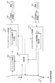
- FIG. 3 is a schematic diagram illustrating an example of a block configuration of the base station apparatus 2 according to the present embodiment.
- the base station apparatus 2 includes an upper layer (upper layer control information notification unit, upper layer processing unit) 501, a control unit (base station control unit) 502, a codeword generation unit 503, a downlink subframe generation unit 504, and an OFDM signal transmission.
- the downlink subframe generation unit 504 includes a downlink reference signal generation unit 505.
- the uplink subframe processing unit 510 includes an uplink control information extraction unit (CSI acquisition unit) 511.
- FIG. 4 is a schematic diagram illustrating an example of a block configuration of the terminal device 1 according to the present embodiment.
- the terminal device 1 includes a reception antenna (terminal reception antenna) 601, an OFDM signal reception unit (downlink reception unit) 602, a downlink subframe processing unit 603, a transport block extraction unit (data extraction unit) 605, a control unit (terminal) Control unit) 606, upper layer (upper layer control information acquisition unit, upper layer processing unit) 607, channel state measurement unit (CSI generation unit) 608, uplink subframe generation unit 609, SC-FDMA signal transmission unit (UCI transmission) Part) 611 and 612 and transmission antennas (terminal transmission antennas) 613 and 614.
- the downlink subframe processing unit 603 includes a downlink reference signal extraction unit 604.
- the uplink subframe generation unit 609 includes an uplink control information generation unit (UCI generation unit) 610.
- UCI generation unit uplink control information generation unit
- the control unit 502 includes MCS (Modulation and Coding Scheme) indicating a downlink modulation scheme and coding rate, downlink resource allocation indicating an RB used for data transmission, and information used for HARQ control ( Redundancy version, HARQ process number, and new data index) are stored, and the codeword generation unit 503 and the downlink subframe generation unit 504 are controlled based on these.
- Downlink data also referred to as a downlink transport block
- processing such as error correction coding and rate matching processing in the codeword generation unit 503 under the control of the control unit 502. And a codeword is generated.
- the downlink subframe generation unit 504 generates a downlink subframe according to an instruction from the control unit 502.
- the codeword generated by the codeword generation unit 503 is converted into a modulation symbol sequence by a modulation process such as PSK (Phase Shift Keying) modulation or QAM (Quadrature Amplitude Modulation) modulation.
- the modulation symbol sequence is mapped to REs in some RBs, and a downlink subframe for each antenna port is generated by precoding processing.
- the transmission data sequence transmitted from the upper layer 501 includes upper layer control information that is control information (for example, dedicated (individual) RRC (Radio Resource Control) signaling) in the upper layer.
- the downlink reference signal generation section 505 generates a downlink reference signal.
- the downlink subframe generation unit 504 maps the downlink reference signal to the RE in the downlink subframe according to an instruction from the control unit 502.
- the downlink subframe generated by the downlink subframe generation unit 504 is modulated into an OFDM signal by the OFDM signal transmission unit 506 and transmitted via the transmission antenna 507.
- a configuration having one OFDM signal transmission unit 506 and one transmission antenna 507 is illustrated here, but when transmitting a downlink subframe using a plurality of antenna ports, transmission is performed with the OFDM signal transmission unit 506.
- a configuration including a plurality of antennas 507 may be employed.
- the downlink subframe generation unit 504 can also have a capability of generating a physical layer downlink control channel such as PDCCH or EPDCCH and mapping it to the RE in the downlink subframe.
- a plurality of base station apparatuses (base station apparatus 2-1 and base station apparatus 2-2) each transmit an individual downlink subframe.
- the OFDM signal is received by the OFDM signal receiving unit 602 via the receiving antenna 601 and subjected to OFDM demodulation processing.
- the downlink subframe processing unit 603 first detects a physical layer downlink control channel such as PDCCH or EPDCCH. More specifically, the downlink subframe processing unit 603 decodes the PDCCH or EPDCCH as transmitted in an area where the PDCCH or EPDCCH can be allocated, and confirms a CRC (Cyclic Redundancy Check) bit added in advance. (Blind decoding) That is, the downlink subframe processing unit 603 monitors PDCCH and EPDCCH.
- a physical layer downlink control channel such as PDCCH or EPDCCH. More specifically, the downlink subframe processing unit 603 decodes the PDCCH or EPDCCH as transmitted in an area where the PDCCH or EPDCCH can be allocated, and confirms a CRC (Cyclic Redundancy Check) bit added in advance. (Blind decoding) That is, the downlink subframe processing
- One CRC bit is assigned to one terminal such as an ID (C-RNTI (Cell-Radio Network Temporary Identifier), SPS-C-RNTI (Semi Persistent Scheduling-C-RNTI), etc.) assigned in advance by the base station apparatus. If it matches the terminal unique identifier or Temporary C-RNTI), the downlink subframe processing unit 603 recognizes that the PDCCH or EPDCCH has been detected, and uses the control information included in the detected PDCCH or EPDCCH to perform PDSCH. Take out.
- C-RNTI Cell-Radio Network Temporary Identifier
- SPS-C-RNTI Semi Persistent Scheduling-C-RNTI
- the control unit 606 holds MCS indicating the modulation scheme and coding rate in the downlink based on the control information, downlink resource allocation indicating the RB used for downlink data transmission, and information used for HARQ control, based on these And controls the downlink subframe processing unit 603, the transport block extraction unit 605, and the like. More specifically, the control unit 606 performs control so as to perform RE demapping processing and demodulation processing corresponding to the RE mapping processing and modulation processing in the downlink subframe generation unit 504.
- the PDSCH extracted from the received downlink subframe is sent to the transport block extraction unit 605.
- the downlink reference signal extraction unit 604 in the downlink subframe processing unit 603 extracts a downlink reference signal from the downlink subframe.
- the transport block extraction unit 605 performs rate matching processing in the codeword generation unit 503, rate matching processing corresponding to error correction coding, error correction decoding, and the like, extracts transport blocks, and sends them to the upper layer 607. It is done.
- the transport block includes upper layer control information, and the upper layer 607 informs the control unit 606 of necessary physical layer parameters based on the upper layer control information.
- the plurality of base station apparatuses 2 (base station apparatus 2-1 and base station apparatus 2-2) transmit individual downlink subframes, and the terminal apparatus 1 receives these, so that The processing may be performed for each downlink subframe for each of the plurality of base station apparatuses 2.
- the terminal device 1 may or may not recognize that a plurality of downlink subframes are transmitted from the plurality of base station devices 2. When not recognizing, the terminal device 1 may simply recognize that a plurality of downlink subframes are transmitted in a plurality of cells. Further, the transport block extraction unit 605 determines whether or not the transport block has been correctly detected, and the determination result is sent to the control unit 606.
- the downlink reference signal extracted by the downlink reference signal extraction unit 604 is sent to the channel state measurement unit 608 under the instruction of the control unit 606, and the channel state measurement unit 608 performs channel state and / or interference. And CSI is calculated based on the measured channel conditions and / or interference.
- the control unit 606 sends the HARQ-ACK (DTX (untransmitted), ACK (successful detection), or NACK ( Detection failure)) and mapping to downlink subframes.
- the terminal device 1 performs these processes on the downlink subframes for each of a plurality of cells.
- Uplink control information generating section 610 generates PUCCH including the calculated CSI and / or HARQ-ACK.
- the PUSCH including the uplink data sent from the higher layer 607 and the PUCCH generated in the uplink control information generation unit 610 are mapped to the RB in the uplink subframe, and the uplink A subframe is generated.
- the uplink subframe is subjected to SC-FDMA modulation in the SC-FDMA signal transmission unit 611 to generate an SC-FDMA signal and transmitted via the transmission antenna 613.
- the terminal device 1 performs (derived) channel measurement for calculating the value of CQI based on CRS or CSI-RS (non-zero power CSI-RS). Whether the terminal device 1 derives based on CRS or CSI-RS is switched by an upper layer signal. Specifically, in a transmission mode in which CSI-RS is set, channel measurement for calculating CQI is derived based only on CSI-RS. Specifically, in a transmission mode in which CSI-RS is not set, channel measurement for calculating CQI is derived based on CRS. An RS used in channel measurement for calculating CSI is also referred to as a first RS.
- the terminal apparatus 1 when the terminal apparatus 1 is set in an upper layer, the terminal apparatus 1 performs (derived) interference measurement for calculating the CQI based on the CSI-IM or the second RS. Specifically, in a transmission mode in which CSI-IM is set, an interference measurement for calculating CQI is derived based on CSI-IM. Specifically, in a transmission mode in which CSI-IM is set, an interference measurement for deriving a CQI value corresponding to the CSI process is derived based only on CSI-IM resources associated with the CSI process.
- the RS or IM used in channel measurement for calculating CSI is also referred to as a second RS.
- the terminal device 1 may perform interference measurement for calculating CQI based on CRS (may be derived). For example, if CSI-IM is not configured, an interference measurement for calculating CQI based on CRS may be derived.
- channel and / or interference for calculating CQI may be used for the channel and / or interference for calculating PMI or RI as well.
- LAA cell The details of the LAA cell will be described below.
- the frequency used by the LAA cell is shared with other communication systems and / or other LTE operators.
- LAA cells require fairness with other communication systems and / or other LTE operators.
- a fair frequency sharing technique (method) is necessary in a communication system used in an LAA cell.
- the LAA cell is a cell that performs a communication method (communication procedure) to which a fair frequency sharing technique can be applied (used).
- LBT Listen-Before-Talk
- LBT listen-Before-Talk
- interference power interference signal, received power, received signal, noise power, noise signal
- the frequency is idle (free, not congested, Absence, Clear) or busy (not free, congested, Presence, Occupied) is identified (detected, assumed, determined).
- the LAA cell can transmit a signal at a predetermined timing at that frequency.
- the LAA cell does not transmit a signal at a predetermined timing at that frequency.
- the LBT can be controlled so as not to interfere with signals transmitted by other base stations and / or terminals including other communication systems and / or other LTE operators.
- the LBT procedure is defined as a mechanism that applies a CCA (Clear Channel Assessment) check before a certain base station or terminal uses the frequency (channel).
- the CCA performs power detection or signal detection to determine the presence or absence of other signals on the channel to identify whether the frequency is idle or busy.
- the definition of CCA may be equivalent to the definition of LBT.
- CCA various methods can be used for determining the presence or absence of other signals. For example, CCA is determined based on whether the interference power at a certain frequency exceeds a certain threshold. Also, for example, CCA is determined based on whether the received power of a predetermined signal or channel at a certain frequency exceeds a certain threshold value.
- the threshold value may be defined in advance. The threshold may be set from the base station or another terminal. The threshold value may be determined (set) based at least on other values (parameters) such as transmission power (maximum transmission power).
- the CCA in the LAA cell does not need to be recognized by the terminal connected (set) to the LAA cell.
- the terminal device 1 may consider that transmission is continuous for several subframes after detecting the first transmission. Several subframes in which transmission continues are also referred to as a transmission burst. The number of subframes transmitted continuously by the transmission burst may be set in the terminal device 1 by the RRC message.
- the LAA cell may be defined as a cell different from the secondary cell using the allocated frequency.
- the LAA cell is set differently from the setting of the secondary cell using the allocated frequency. Some of the parameters set in the LAA cell are not set in the secondary cell using the allocated frequency. Some of the parameters set in the secondary cell using the allocated frequency are not set in the LAA cell.
- the LAA cell is described as a cell different from the primary cell and the secondary cell, but the LAA cell may be defined as one of the secondary cells.
- the conventional secondary cell is also referred to as a first secondary cell, and the LAA cell is also referred to as a second secondary cell.
- the conventional primary cell and secondary cell are also referred to as a first serving cell, and the LAA cell is also referred to as a second serving cell.
- the LAA cell may be different from the conventional frame configuration type.
- the conventional serving cell uses (sets) the first frame configuration type (FDD, frame structure type 1) or the second frame configuration type (TDD, frame structure type 2), while the LAA cell A third frame configuration type (frame structure type 3) is used (set).
- the LAA cell may use the first frame configuration type or the second frame configuration type (may be set).
- the third frame configuration type is preferably a frame configuration type having characteristics of an FDD cell while being a TDD cell in which uplink and downlink can be transmitted at the same frequency.
- the third frame configuration type includes an uplink subframe, a downlink subframe, and a special subframe, and the PUSCH scheduled from the uplink grant after receiving the uplink grant is The interval until transmission or the interval of HARQ feedback for the PDSCH after receiving the PDSCH may be the same as that of the FDD cell.
- the third frame configuration type is preferably a frame configuration type that does not depend on the conventional TDD UL / DL configuration (TDD uplink / downlink configuration).
- the uplink subframe, the downlink subframe, and the special subframe may be set aperiodically with respect to the radio frame.
- the uplink subframe, the downlink subframe, and the special subframe may be determined based on PDCCH or EPDCCH.
- the non-assigned frequency is a frequency different from the assigned frequency assigned as a dedicated frequency to a predetermined operator.
- the unassigned frequency is a frequency used by the wireless LAN.
- the non-assigned frequency is a frequency that is not set in the conventional LTE
- the assigned frequency is a frequency that can be set in the conventional LTE.
- the frequency set in the LAA cell is described as an unassigned frequency, but is not limited to this. That is, the unassigned frequency can be replaced with a frequency set in the LAA cell.
- the non-assigned frequency is a frequency that cannot be set in the primary cell and can be set only in the secondary cell.
- unassigned frequencies also include frequencies that are shared with multiple operators. Further, for example, the unassigned frequency is a frequency that is set only for a cell that is set, assumed, and / or processed differently from a conventional primary cell or secondary cell.
- the LAA cell may be a cell that uses a scheme different from the conventional scheme with regard to the configuration and communication procedures of LTE radio frames, physical signals, and / or physical channels.
- a predetermined signal and / or channel set (transmitted) in the primary cell and / or the secondary cell is not set (transmitted).
- the predetermined signal and / or channel includes CRS, DS, PDCCH, EPDCCH, PDSCH, PSS, SSS, PBCH, PHICH, PCFICH, CSI-RS, and / or SIB.
- signals and / or channels that are not set in the LAA cell are as follows. The signals and / or channels described below may be used in combination. In the present embodiment, signals and / or channels that are not set in the LAA cell may be read as signals and / or channels that the terminal does not expect from the LAA cell.
- the physical layer control information is not transmitted on the PDCCH, but is transmitted only on the EPDCCH.
- CRS, DMRS, URS, PDCCH, EPDCCH and / or PDSCH are not transmitted in all subframes even in a subframe that is activated (on), and the terminal transmits in all subframes. Do not assume that it is.
- the terminal transmits DRS, PSS, and / or SSS in the activation (ON) subframe.
- the terminal is notified of information on CRS mapping for each subframe, and makes a CRS mapping assumption based on the information.
- the CRS mapping assumption is not mapped to all resource elements of that subframe.
- the assumption of CRS mapping is not mapped to some resource elements of the subframe (for example, all resource elements in the first two OFDM symbols).
- CRS mapping assumptions are mapped to all resource elements of that subframe.
- information on CRS mapping is notified from the LAA cell or a cell different from the LAA cell.
- Information on CRS mapping is included in DCI and is notified by PDCCH or EPDCCH.
- a predetermined signal and / or channel that is not set (transmitted) in the primary cell and / or the secondary cell is set (transmitted).
- only downlink component carriers or subframes are defined, and only downlink signals and / or channels are transmitted. That is, in the LAA cell, no uplink component carrier or subframe is defined, and no uplink signal and / or channel is transmitted.
- the DCI (Downlink Control Information) format that can be supported is different from the DCI format that can correspond to the primary cell and / or the secondary cell.
- a DCI format corresponding only to the LAA cell is defined.
- the DCI format corresponding to the LAA cell includes control information effective only for the LAA cell.
- the assumption of signals and / or channels is different from that of the conventional secondary cell.
- a terminal satisfying a part or all of the following conditions, except for transmission of DS has PSS, SSS, PBCH, CRS, PCFICH, PDSCH, PDCCH, EPDCCH, PHICH, DMRS and / or CSI-RS as its secondary cell. Assume that it may not be sent by. The terminal also assumes that the DS is always transmitted by the secondary cell. Further, the assumption continues until a subframe in which an activation command (command for activation) is received in a secondary cell at a certain carrier frequency of the terminal.
- an activation command command for activation
- the terminal supports settings (parameters) related to DS.
- the RRM measurement based on the DS is set in the secondary cell of the terminal.
- the secondary cell is in a deactivated state.
- the terminal is not set to receive MBMS by the upper layer in the secondary cell.
- the terminal when the secondary cell is in an activated state (activated state), the terminal performs PSS, SSS, PBCH, CRS, PCFICH, PDSCH, PDCCH, in a set predetermined subframe or all subframes. Assume that EPDCCH, PHICH, DMRS and / or CSI-RS are transmitted by the secondary cell.
- a terminal that satisfies some or all of the following conditions includes the transmission of DS, PSS, SSS, PBCH, CRS, PCFICH, PDSCH, PDCCH, EPDCCH, PHICH, DMRS, and / or CSI-RS in its LAA cell Assume that it may not be sent by. Further, the assumption continues until a subframe in which an activation command (command for activation) is received in a secondary cell at a certain carrier frequency of the terminal.
- the terminal supports settings (parameters) related to DS.
- the RRM measurement based on the DS is set in the LAA cell of the terminal.
- the terminal is not set to receive MBMS by the upper layer in the LAA cell.
- the terminal determines that the LAA cell is PSS, SSS, PBCH, CRS, except for a predetermined subframe set in the LAA cell. Assume that PCFICH, PDSCH, PDCCH, EPDCCH, PHICH, DMRS and / or CSI-RS may not be transmitted. Details thereof will be described later.
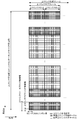
- FIG. 5 is a diagram illustrating an example of a communication procedure in a certain LAA cell.
- FIG. 5 shows 10 subframes indicated by subframes # 0 to # 9 and 14 symbols (OFDM symbols) of symbols # 0 to # 13 in subframe # 3.
- the LAA cell can transmit a signal of a maximum of 4 milliseconds (corresponding to 4 subframes), and CCA is performed at symbol # 5 in subframe # 3.
- the LAA cell is assumed to be able to transmit a signal from a symbol immediately after identifying that the frequency is idle in the CCA.
- the LAA cell transmits a signal from symbol # 6 in subframe # 3 to a predetermined symbol in subframe # 6.
- the LAA indicates that nothing is transmitted.
- the LAA in a symbol or subframe indicated by a symbol / subframe in which a channel and / or signal is transmitted (transmittable), the LAA includes at least a PDSCH and a terminal-specific reference signal associated with the PDSCH. Indicates sending.
- the PDSCH is mapped (scheduled) to each terminal in units of resource block pairs.
- Information on the mapping (scheduling) is notified through PDCCH or EPDCCH transmitted in each subframe.
- the mapping information for PDSCH in a certain subframe may be notified in the same subframe, or may be notified in another subframe.
- the recognition method information for recognizing a symbol for transmitting a channel and / or a signal in a predetermined subframe (for example, subframe # 3) of the LAA cell is used.
- the information is any of the following or a combination thereof.
- the information is information indicating a start symbol of a symbol to which a channel and / or a signal is transmitted in the predetermined subframe.
- the information indicating the start symbol is any one of 0 to 13, and each value indicates a symbol number that becomes a start symbol.
- the information is information indicating a start symbol of a symbol to which a channel and / or a signal is transmitted in the predetermined subframe.
- the information indicating the start symbol is index information in which a predetermined value is indexed from 0 to 13.
- the information is bitmap information indicating a symbol in which a channel and / or a signal is transmitted in the predetermined subframe.
- the bitmap information is composed of 14 bits. In the bitmap information, when each bit is in one state (eg, 1), it indicates the symbol on which the channel and / or signal is transmitted, and when each bit is in the other state (eg, 0), Indicates a channel and / or symbol on which no signal is transmitted.
- the information is information indicating the last symbol of a symbol for which a channel and / or signal is not transmitted in the predetermined subframe, or information indicating the number of symbol symbols for which a channel and / or signal is not transmitted.
- the last symbol is any one of 0 to 13
- each value indicates a symbol number that is the last symbol.
- the information indicating the number of symbols is any one of 1 to 14, and each value indicates the number of symbols.
- the information is information indicating the last symbol of a symbol for which a channel and / or signal is not transmitted in the predetermined subframe, or information indicating the number of symbol symbols for which a channel and / or signal is not transmitted.
- the last symbol is index information in which a predetermined value is indexed from 0 to 13.
- the information indicating the number of symbols is index information in which a predetermined value is indexed from values 1 to 14.
- the information is notified by parameters set (notified) to the LAA cell through RRC signaling or MAC signaling.
- a serving cell is an LAA cell
- a channel and / or signal is not transmitted for a configured symbol and a channel and / or signal is transmitted for another symbol in a subframe.
- a symbol in which a channel and / or a signal is not transmitted is set as symbols # 0 and # 1 in a certain subframe.
- Symbols for which channels and / or signals are not transmitted are set as symbols # 2 to # 13 in a certain subframe.
- this setting may be different (independent) depending on the channel and / or signal.
- the terminal is set when EPDCCH is mapped to symbols # 2 to # 13, and is set when PDSCH is mapped to symbols # 1 to # 13.
- the PDSCH start symbol range (possible values) set for the LAA cell is different from the PDSCH start symbol range (1 to 4) set for the conventional secondary cell. Can do.
- the range of PDSCH and / or EPDCCH start symbols set for the LAA cell is 0-13.
- the information is notified by PDCCH or EPDCCH transmitted from the LAA cell or a serving cell (assist cell, primary cell, or secondary cell) different from the LAA cell.
- the DCI carried (transmitted) by the PDCCH or EPDCCH contains that information.
- the information is notified by a channel or signal for notifying the information.
- the channel or signal for notifying the information is transmitted only to the LAA cell.
- the channel or signal for notifying the information is transmitted from the LAA cell or a serving cell (assist cell, primary cell, or secondary cell) different from the LAA cell.
- the information candidate is set (notified) to the LAA cell through RRC signaling or MAC signaling.
- the candidate information is selected based on information included in DCI carried (transmitted) by PDCCH or EPDCCH. For example, information indicating four start symbols is set through RRC signaling or MAC signaling, and 2-bit information indicating one of them is notified by PDCCH or EPDCCH signaling.
- the information is notified by a channel or signal mapped to a predetermined resource element in a certain subframe.
- the predetermined resource element is a plurality of resource elements in a predetermined symbol.
- the predetermined symbol is the last symbol in the subframe.
- the subframe to which the channel or signal for notifying the information is mapped may be all subframes in the LAA cell, or may be a subframe defined in advance or a subframe set by RRC signaling. May be.
- a serving cell is an LAA cell
- a channel and / or signal is not transmitted for a predetermined symbol and a channel and / or signal is transmitted for another symbol in a subframe.
- symbols in which no channel and / or signal are transmitted are symbols # 0 and 1 in a certain subframe.
- Symbols for which channels and / or signals are not transmitted are symbols # 2 to # 13 in a certain subframe.
- This definition may also be different (independent) for each channel and / or signal. For example, in a certain subframe, the terminal assumes that EPDCCH is mapped to symbols # 2 to 13 and PDSCH is mapped to symbols # 1 to 13.
- the terminal detects a symbol on which a channel and / or a signal is transmitted in a predetermined subframe (for example, subframe # 3) of the LAA cell.
- the terminal may be set with assist information for performing the detection. For example, the following method is used as the detection method.
- the detection is performed based on a predetermined signal mapped to the predetermined subframe.
- the terminal detects a symbol on which a channel and / or signal is transmitted based on whether a predetermined signal or a set signal is detected in the predetermined subframe.
- the terminal transmits a channel and / or a signal after the certain symbol in the predetermined subframe. Is recognized as a symbol.
- the predefined signal or the set signal is CRS, DMRS, and / or URS.
- the detection is performed based on a predetermined channel mapped to the predetermined subframe.
- the terminal detects a symbol on which a channel and / or signal is transmitted based on whether a predetermined channel or a set channel is detected in the predetermined subframe.
- the terminal transmits a channel and / or a signal after the certain symbol in the predetermined subframe.
- the predefined channel or the set channel is EPDCCH.
- the terminal performs EPDCCH monitoring (detection process, blind detection) on the assumption that the EPDCCH is mapped to symbols after a certain symbol in the predetermined subframe.
- the terminal may perform blind detection of a start symbol that is assumed to be mapped with EPDCCH.
- a start symbol or a candidate for a start symbol that is assumed to be mapped with EPDCCH may be defined in advance or set.
- mapping method of PDCCH, EPDCCH and / or PDSCH to resource elements may be different from the mapping method in other subframes.
- the following method can be used as the mapping method.
- the following mapping method (mapping order) can be applied to other signals such as a reference signal and a synchronization signal.
- mapping method PDCCH, EPDCCH and / or PDSCH are mapped from the last symbol in the subframe. That is, the mapping of PDCCH, EPDCCH and / or PDSCH to resource element (k, l) is an allocated physical resource block, and in the resource element that can be mapped, the OFDM symbol having the largest OFDM symbol number l (that is, , The last symbol in the slot). Mapping is performed in order from the last slot (second slot) of the subframe. In each OFDM symbol, these channels are mapped in order from the subcarrier having the smallest subcarrier number k.
- mapping method PDCCH, EPDCCH and / or PDSCH are mapped to resource elements in symbols in which channels and / or signals are transmitted by skipping symbols in which channels and / or signals are not transmitted. The That is, in the mapping of PDCCH, EPDCCH, and / or PDSCH, resource elements of symbols in which channels and / or signals are not transmitted are rate-matched.
- the mapping method is such that PDCCH, EPDCCH and / or PDSCH are mapped to resource elements in symbols in which channels and / or signals are transmitted without skipping symbols in which channels and / or signals are not transmitted. Is done.
- the PDCCH, EPDCCH, and / or PDSCH are applied without mapping between symbols where channels and / or signals are transmitted and symbols where channels and / or signals are not transmitted, but channels and / or signals.
- Channels that are mapped to symbols that are not transmitted are not transmitted, and channels that are mapped to symbols where channels and / or signals are transmitted are transmitted. That is, in the mapping of PDCCH, EPDCCH and / or PDSCH, resource elements of symbols in which channels and / or signals are not transmitted are punctured.
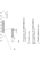
- FIG. 6 is a diagram illustrating an example of a communication procedure in a certain LAA cell.
- CCA is performed on symbol # 5 in subframe # 3.
- the LAA cell is assumed to be able to transmit a signal from a symbol immediately after identifying that the frequency is idle in the CCA.
- the LAA cell transmits a signal from symbol # 5 in subframe # 3 to a predetermined symbol in subframe # 6.
- symbols # 6 and 7 in subframe # 3 are symbols to which a reservation signal is transmitted.
- the reserved signal is transmitted from immediately after the symbol performing CCA (ie, symbol # 5) to immediately before the symbol (ie, symbol # 6) where the channel and / or signal is transmitted.
- the effect of this reservation signal is as follows. As described in FIG. 5, even when a candidate for a symbol on which a channel and / or a signal is transmitted is predetermined or set, the LAA cell does not depend on the number of candidates for CCA. It can be done flexibly.
- the reservation signal may not be received (recognized) even by a terminal that receives a channel and / or signal transmitted from the LAA cell. That is, when a channel and / or signal cannot be transmitted after performing CCA, the reservation signal is transmitted in order to secure (reserve) the frequency of the LAA cell that performed the CCA.
- the channel and / or signal different from the channel and / or signal transmitted in the channel and / or symbol in which the signal is transmitted may be mapped to the symbol in which the reservation signal is transmitted. That is, the channel and / or signal mapped to the symbol for which the reservation signal is transmitted is recognized (received) by the terminal. For example, the terminal identifies the symbol on which the channel and / or signal is transmitted based on the channel and / or signal that is mapped to the symbol on which the reservation signal is transmitted. Also, for example, the terminal synchronizes (identifies) with the LAA cell using a channel and / or signal mapped to a symbol in which a reservation signal is transmitted.
- the reservation signal is preferably composed of a combination of a plurality of signals.
- it is preferably configured by a combination of a signal having an OFDM symbol configuration and a signal shorter than the OFDM symbol length.
- a part of the reservation signal has a signal configuration suitable for synchronization, such as PSS and SSS.
- a part of the reservation signal is constituted by an ID for identifying a transmission point (and an operator).
- a part of the reservation signal is transmitted by one symbol or more.
- a part of the reservation signal may be an RS for CSI measurement.
- the reservation signal and the CSI-RS may be set as an apparent same position (quasi co-location) when observed from the terminal device 1.
- FIG. 7 is a diagram illustrating an example of a communication procedure in a certain LAA cell.
- CCA is performed on symbol # 5 in subframe # 3, as in the example of FIG.
- the LAA cell is assumed to be able to transmit a signal from a symbol immediately after identifying that the frequency is idle in the CCA.
- the LAA cell transmits a signal from symbol # 6 in subframe # 3 to symbol # 5 in subframe # 7 after 4 milliseconds.
- the LAA cell transmits a reservation signal from the symbol immediately after the symbol for performing CCA to the last symbol in the subframe including the symbol for performing CCA. Further, the LAA cell transmits a channel and / or a signal from a subframe next to a subframe including a symbol for performing CCA.
- the reservation signal in FIG. 7 includes the reservation signal described in FIG.
- the terminal can assume that a channel and / or a signal is transmitted in a subframe after subframe # 4. Thereby, the terminal assumes that the channel and / or signal is transmitted from the first symbol of the subframe. Therefore, a base station including an LAA cell can use a method similar to the conventional method for transmitting a channel and / or signal to the terminal and notifying control information for the channel and / or signal. .
- the LAA cell can transmit a channel and / or signal from the first symbol to symbol # 5 in subframe # 7.
- the LAA cell can transmit PDSCH and / or EPDCCH mapped to resources from a predetermined symbol to symbol # 5 in subframe # 7 to the terminal.
- the LAA cell can transmit a PDCCH mapped to resources from the first symbol to a predetermined symbol in subframe # 7 to the terminal.
- the predetermined symbol is information transmitted by PCFICH, and is determined based on information on the number of OFDM symbols used for transmission of PDCCH.
- the predetermined symbol is control information set by RRC signaling, and is determined based on information indicating an OFDM start symbol for the PDSCH scheduled by the EPDCCH, the PDCCH, and the PDSCH scheduled by the EPDCCH. .
- the LAA cell can notify or set the last symbol in which the channel and / or signal is transmitted in subframe # 7.
- the information described in the example of FIG. 5 can be used as information for the terminal to recognize the last symbol in a certain subframe of the LAA cell and a method for notifying the information.
- the method described in the example of FIG. 5 is information for recognizing a symbol and a channel and / or a signal transmitted in FIG.
- the LAA cell includes information related to the last symbol in DCI notified by PDCCH or EPDCCH transmitted in subframe # 7. Thereby, the LAA cell can efficiently use resources when a channel and / or signal can be transmitted up to a symbol in the middle of a subframe, as in subframe # 7 in FIG.
- the LAA cell includes information on the last symbol in information set by RRC signaling or MAC signaling.
- the transmission method in subframe # 3 and the transmission method in subframe # 7 are used in combination has been described, but the present invention is not limited to this.
- the transmission method in subframe # 3 and the transmission method in subframe # 7 may be used independently. Further, some or all of the methods described in FIGS. 5 to 7 may be used in combination.
- mapping of PDCCH, EPDCCH and / or PDSCH to resource elements may be different from the mapping in other subframes.
- subframes that can transmit channels and / or signals to all OFDM symbols in one subframe are part of one subframe. Is recognized, set, or notified as a subframe different from a subframe in which a channel and / or signal cannot be transmitted in the OFDM symbol (ie, subframe # 3 in FIGS. 5 to 7 and subframe # 7 in FIG. 7). May be.
- a subframe that can transmit a channel and / or signal to all OFDM symbols in one subframe is equivalent to a subframe in a conventional serving cell.
- a subframe in which a channel and / or signal cannot be transmitted to all OFDM symbols in one subframe is also referred to as a first LAA subframe.
- a subframe in which a channel and / or signal cannot be transmitted in some OFDM symbols in one subframe is also referred to as a second LAA subframe.
- a subframe that can transmit a channel and / or signal to all OFDM symbols in one subframe is also referred to as a third LAA subframe.
- the method described in this embodiment can be used.
- the method described in this embodiment can be used as a method for recognizing them.
- information for recognizing a channel and / or symbol on which a signal is transmitted and a notification method thereof are used.
- a method for the terminal to recognize the first LAA subframe, the second LAA subframe, and the third LAA subframe may be explicitly notified or configured by PDCCH or RRC signaling.
- a method for the terminal to recognize the first LAA subframe, the second LAA subframe, and the third LAA subframe is based on information (parameter) notified or set by PDCCH or RRC signaling. May be implicitly notified or set.
- the terminal recognizes a first LAA subframe, a second LAA subframe, and a third LAA subframe based on information on CRS mapping.
- the terminal When the terminal recognizes that a certain subframe is the second LAA subframe, the terminal recognizes that a predetermined number of subframes after the next subframe are the third LAA subframe. . The terminal also recognizes the first LAA subframe until the subframe subsequent to the last subframe recognized as the third LAA subframe is the second LAA subframe. Recognize that The predetermined number (that is, the number of subframes recognized as being the third LAA subframe) may be defined in advance. The predetermined number may be set in the LAA cell. The predetermined number may be reported by a channel and / or signal mapped to the second LAA subframe.
- start symbols of PDSCH and / or EPDCCH are respectively defined or set independently.
- the time for performing CCA may vary for each LAA cell, for each timing of CCA, and for each execution of CCA.
- CCA is performed at a time based on a predetermined time slot (time interval, time domain).
- the predetermined time slot may be defined or set by a time obtained by dividing one subframe into a predetermined number.
- the predetermined time slot may be defined or set by a predetermined number of subframes.
- the size of the field in the time domain is a predetermined time unit.
- the size of the field in the time domain is expressed as several time units Ts. Ts is 1 / (15000 * 2048) seconds. For example, the time of one subframe is 30720 * Ts (1 millisecond).
- whether a channel and / or a signal (including a reservation signal) can be transmitted from a symbol in the middle of a subframe in which a LAA cell exists is determined by whether the terminal or the LAA cell May be set. For example, information indicating whether or not such transmission is possible is set in the terminal regarding the LAA cell by RRC signaling. Based on the information, the terminal switches processing related to reception (monitoring, recognition, decoding) in the LAA cell.
- subframes that can be transmitted from intermediate symbols may be all subframes in the LAA cell.
- the subframe that can be transmitted from a halfway symbol may be a subframe previously defined for the LAA cell or a set subframe.
- subframes that can be transmitted from intermediate symbols are set, notified, or determined based on the TDD uplink downlink configuration (UL / DL configuration).
- a subframe is a subframe notified (designated) as a special subframe in the UL / DL setting.
- the special subframe in the LAA cell is a subframe including at least one of three fields of DwPTS (Downlink Pilot Time Slot), GP (Guard Period) and UpPTS (Uplink Pilot Time Slot).
- the setting related to the special subframe in the LAA cell may be set or notified by RRC signaling, PDCCH or EPDCCH signaling.
- This setting sets the length of time for at least one of DwPTS, GP and UpPTS.
- This setting is index information indicating candidates for a predetermined length of time.
- This setting can use the same length of time as DwPTS, GP, and UpPTS used in the special subframe setting set in the conventional TDD cell. That is, the length of time during which transmission is possible in a certain subframe is determined based on one of DwPTS, GP, and UpPTS.
- the reservation signal can be a signal that can be received by an LAA cell different from the LAA cell that is transmitting the reservation signal.
- an LAA cell different from the LAA cell that transmits the reservation signal is an LAA cell (adjacent LAA cell) that is adjacent to the LAA cell that transmits the reservation signal.
- the reservation signal includes information regarding a transmission status (usage status) of a predetermined subframe and / or symbol in the LAA cell.
- the LAA cell that has received the reservation signal uses a predetermined subframe and / or symbol based on the reservation signal. Recognize the transmission status and perform scheduling according to the status.
- the LAA cell that has received the reservation signal may perform LBT before transmitting the channel and / or signal.
- the LBT is performed based on the received reservation signal. For example, in the LBT, scheduling including resource allocation and MCS selection is performed in consideration of a channel and / or signal transmitted (assumed to be transmitted) by the LAA cell that transmitted the reservation signal.
- the predetermined method is a method of transmitting a predetermined channel and / or signal including a reservation signal. Further, for example, the predetermined method is a method of notifying through a backhaul such as an X2 interface.
- the conventional terminal can set up to five serving cells, but the terminal in the present embodiment can expand the maximum number of serving cells that can be set. That is, the terminal in this embodiment can set up more than five serving cells. For example, the terminal in this embodiment can set up to 16 or 32 serving cells. For example, more than five serving cells set in the terminal in the present embodiment include LAA cells. In addition, all of the five serving cells set in the terminal in the present embodiment may be LAA cells.
- the settings for some serving cells may be different from the settings for the conventional serving cell (ie, the conventional secondary cell).
- the setting may be used in combination.
- the terminal is configured with up to 5 conventional serving cells and up to 11 or 27 serving cells different from the conventional one. That is, the terminal is configured with up to four conventional secondary cells in addition to the conventional primary cell, and with up to 11 or 27 secondary cells different from the conventional one.
- Settings related to a serving cell (secondary cell) different from conventional settings include settings related to an LAA cell.
- the terminal sets up to four secondary cells that do not include settings related to the LAA cell, and sets up to 11 or 27 secondary cells different from the conventional one.
- the base station (including the LAA cell) and / or the terminal can perform processing or assumption different from that when setting up to five serving cells.
- the processing or assumption the following is different.
- the processes or assumptions described below may be used in combination.
- the terminal can use a method similar to the conventional method for reception of PDCCH, EPDCCH and / or PDSCH and transmission of HARQ-ACK for the PDSCH.
- the terminal sets a combination (group) of cells that perform HARQ-ACK bundling for the PDSCH in those serving cells.
- all serving cells, all secondary cells, all LAA cells, or all non-conventional secondary cells each include information (setting) on HARQ-ACK bundling between serving cells.
- information related to HARQ-ACK bundling between serving cells is an identifier (index, ID) for performing bundling.
- HARQ-ACK is bundled across cells having the same identifier for bundling.
- the bundling is performed by a logical product operation on the target HARQ-ACK.
- the maximum number of identifiers for bundling can be 5.
- the maximum number of identifiers for performing bundling can be set to 5 including the number of cells for which bundling is not performed. That is, the maximum number of groups that perform bundling beyond the serving cell can be five. Accordingly, the terminal can use a method similar to the conventional method for reception of PDCCH, EPDCCH and / or PDSCH and transmission of HARQ-ACK for the PDSCH.
- the terminal sets a cell combination (group) for performing HARQ-ACK multiplexing on the PDSCH in those serving cells.
- a combination (group) of cells for performing HARQ-ACK multiplexing on the PDSCH is set, the multiplexed HARQ-ACK is transmitted by PUCCH or PUSCH based on the group.
- the maximum number of serving cells to be multiplexed is defined or set. The maximum number is defined or set based on the maximum number of serving cells set in the terminal. For example, the maximum number is the same as the maximum number of serving cells set in the terminal, or half the maximum number of serving cells set in the terminal. Further, the maximum number of PUCCHs transmitted simultaneously is defined or set based on the maximum number of serving cells multiplexed in each group and the maximum number of serving cells set in the terminal.
- the number of set first serving cells (that is, primary cells and / or secondary cells) is a predetermined number (that is, 5) or less, and the set first serving cells and second serving cells ( That is, the total of LAA cells) exceeds the predetermined number.
- terminal capabilities related to LAA will be described.
- the terminal Based on an instruction from the base station, the terminal notifies (transmits) information (terminal capability) on the capability (capability) of the terminal to the base station through RRC signaling.
- the terminal capability for a certain function (feature) is notified (transmitted) when the function (feature) is supported, and is not notified (transmitted) when the function (feature) is not supported.
- the terminal capability for a certain function (feature) may be information indicating whether the test and / or implementation of the function (feature) has been completed.
- the terminal capabilities in this embodiment are as follows. The terminal capabilities described below may be used in combination.
- the terminal capabilities related to support of LAA cells and the terminal capabilities related to support of setting of more than five serving cells are defined independently.
- a terminal that supports LAA cells supports setting up more than five serving cells. That is, a terminal that does not support setting of more than five serving cells does not support LAA cells. In that case, a terminal that supports setting of more than five serving cells may or may not support the LAA cell.
- the terminal capabilities related to support of LAA cells and the terminal capabilities related to support of setting of more than five serving cells are defined independently.
- a terminal that supports setting up more than five serving cells supports LAA cells. That is, a terminal that does not support the LAA cell does not support setting of more than five serving cells. In that case, the terminal supporting the LAA cell may or may not support setting of more than five serving cells.
- the terminal capabilities related to the downlink in the LAA cell and the terminal capabilities related to the uplink in the LAA cell are defined independently.
- a terminal that supports uplink in the LAA cell supports downlink in the LAA cell. That is, a terminal that does not support the downlink in the LAA cell does not support the uplink in the LAA cell. In that case, the terminal that supports the downlink in the LAA cell may or may not support the uplink in the LAA cell.
- Terminal capabilities related to LAA cell support include support for the transmission mode set only in the LAA cell.
- the terminal capabilities related to the downlink in the setting of more than five serving cells and the terminal capabilities related to the uplink in the setting of more than five serving cells are defined independently.
- a terminal that supports uplink in a configuration of more than five serving cells supports a downlink in a configuration of more than five serving cells. That is, a terminal that does not support the downlink in the configuration of more than five serving cells does not support the uplink in the configuration of more than five serving cells.
- the terminal that supports the downlink in the configuration of more than five serving cells may or may not support the uplink in the configuration of more than five serving cells.
- the terminal capability supporting the setting of up to 16 downlink serving cells (component carriers) and the terminal capability supporting the setting of up to 32 downlink serving cells are: Are defined independently.
- a terminal that supports setting of up to 16 downlink serving cells supports setting of at least one uplink serving cell.
- a terminal that supports setting up to 32 downlink serving cells supports setting up at least two uplink serving cells. That is, a terminal that supports setting of up to 16 downlink serving cells may not support setting of two or more uplink serving cells.
- the terminal capabilities related to LAA cell support are notified based on the frequency (band) used in the LAA cell. For example, in the notification of the frequency or combination of frequencies supported by the terminal, if the notified frequency or combination of frequencies includes at least one frequency used in the LAA cell, the terminal implicitly supports the LAA cell. Notice. That is, if the notified frequency or combination of frequencies does not include any frequency used in the LAA cell, the terminal implicitly notifies that it does not support the LAA cell.
- the present invention is not limited to this. Is not to be done.
- a serving cell different from the LAA cell transmits PDCCH or EPDCCH for notifying DCI for PDSCH transmitted in the LAA cell (that is, in the case of cross-carrier scheduling)
- this embodiment will be described. Applied methods are applicable.
- information for recognizing a symbol for transmitting a channel and / or signal may be based on a symbol for which a channel and / or signal is not transmitted.
- the information is information indicating the last symbol of a symbol for which a channel and / or signal is not transmitted.
- information for recognizing a symbol on which a channel and / or signal is transmitted may be determined based on other information or parameters.
- the symbol for transmitting the channel and / or signal may be set (notified or specified) independently for the channel and / or signal.
- information for recognizing a symbol for transmitting a channel and / or a signal and a notification method thereof can be set (notified or defined) independently for each channel and / or signal.
- information for recognizing a channel and / or symbol on which a signal is transmitted and a notification method thereof can be set (notified and specified) independently for PDSCH and EPDCCH.
- a symbol / subframe in which a channel and / or signal is not transmitted is a symbol / subframe in which a channel and / or signal is not assumed to be transmitted (can be transmitted) from the viewpoint of the terminal. It is good. That is, the terminal can consider that the LAA cell is not transmitting a channel and / or signal in the symbol / subframe.
- the symbol / subframe in which the channel and / or signal is transmitted is the symbol / subframe in which the channel and / or signal may be transmitted from the viewpoint of the terminal. It is good. That is, the terminal may consider that the LAA cell may or may not be transmitting a channel and / or signal in that symbol / subframe.
- a symbol / subframe in which a channel and / or signal is transmitted (transmittable) is a symbol / subframe that is assumed to be transmitted from the terminal point of view. Also good. That is, the terminal can consider that the LAA cell always transmits a channel and / or signal in the symbol / subframe.
- An upper layer process that is a terminal device that communicates with a base station device and sets at least one first serving cell (for example, a primary cell and / or a secondary cell) and at least one second serving cell (for example, an LAA cell) And a receiving unit that receives the physical downlink shared channel in the first serving cell and / or the second serving cell.
- the physical downlink shared channel in the first serving cell is mapped to the last OFDM symbol in all subframes
- the physical downlink shared channel in the second serving cell is mapped to the first OFDM symbol in a predetermined subframe. To be mapped.
- the receiving unit receives a physical downlink control channel mapped to the second OFDM symbol or an extended physical downlink control channel mapped to the first OFDM symbol in a predetermined subframe of the second serving cell.
- the physical downlink control channel or the extended physical downlink control channel includes a downlink control information format used for scheduling of the physical downlink shared channel.
- the first OFDM symbol is notified by information transmitted using the downlink control information format.
- the first OFDM symbol and the second OFDM symbol are set independently by higher layer signaling.
- the receiving unit receives the physical downlink shared channel mapped to the last OFDM symbol in each of a predetermined number of subframes before the predetermined subframe.
- the first OFDM symbol is notified using DwPTS in the special subframe of the TDD cell.
- a base station apparatus that communicates with a terminal apparatus, an upper layer processing unit that sets at least one first serving cell and at least one second serving cell in the terminal apparatus, and the first serving cell and / or the second serving cell And a transmission unit for transmitting the physical downlink shared channel.
- the physical downlink shared channel in the first serving cell is mapped to the last OFDM symbol in all subframes.
- the physical downlink shared channel in the second serving cell is mapped up to the first OFDM symbol in a predetermined subframe.
- a terminal device that communicates with a base station device, and an upper layer processing unit that sets at least one first serving cell and at least one second serving cell, and physical downlink in the first serving cell and / or the second serving cell
- a receiving unit that receives the link shared channel.
- the physical downlink shared channel in the first serving cell is mapped after the first OFDM symbol set by higher layer signaling in all subframes.
- the physical downlink shared channel in the second serving cell is mapped after the second OFDM symbol in a predetermined subframe.
- the receiving unit receives an extended physical downlink control channel mapped after the third OFDM symbol in a predetermined subframe of the second serving cell.
- the extended physical downlink control channel includes a downlink control information format used for scheduling of the physical downlink shared channel.
- the second OFDM symbol is notified by information transmitted using the downlink control information format.
- the second OFDM symbol and the third OFDM symbol are set independently by higher layer signaling.
- the receiving unit receives the PDSCH mapped from the first OFDM symbol to the last OFDM symbol in each of a predetermined number of subframes after the predetermined subframe.
- a base station apparatus that communicates with a terminal apparatus, an upper layer processing unit that sets at least one first serving cell and at least one second serving cell in the terminal apparatus, and the first serving cell and / or the second serving cell And a transmission unit for transmitting the physical downlink shared channel.
- the physical downlink shared channel in the first serving cell is mapped after the first OFDM symbol set by higher layer signaling in all subframes.
- the physical downlink shared channel in the second serving cell is mapped after the second OFDM symbol in a predetermined subframe.
- a terminal apparatus that communicates with a base station apparatus, and includes an upper layer processing unit that sets at least one first serving cell and at least one second serving cell. Any one of the first serving cells is a primary cell.
- the first serving cell other than the primary cell is a secondary cell.
- the second serving cell is a secondary cell.
- the setting of the secondary cell that is the second serving cell is different from the setting of the secondary cell that is the first serving cell.
- the frequency that can be set for the first serving cell and the frequency that can be set for the second serving cell are different.
- the second serving cell is different from the first serving cell with respect to signal and / or channel assumptions in the activated state.
- the assumption of signals and / or channels in the activated state is determined for each subframe.
- a signal and / or channel is not mapped to a predetermined OFDM symbol set by higher layer signaling.
- the number of first serving cells to be set is equal to or less than a predetermined number, and the total number of first serving cells and second serving cells to be set exceeds a predetermined number.
- a downlink channel and an uplink channel are supported in the first serving cell. Only the downlink channel is supported in the second serving cell.
- a base station device that communicates with a terminal device, and includes an upper layer processing unit that sets at least one first serving cell and at least one second serving cell in the terminal device. Any one of the first serving cells is a primary cell. The first serving cell other than the primary cell is a secondary cell. The second serving cell is a secondary cell. The setting of the secondary cell that is the second serving cell is different from the setting of the secondary cell that is the first serving cell.
- RSSI Received Signal Strength Indicator
- RSRP Reference Signal Received Quality
- RSRQ Reference Signal Received Quality
- RSSI is the average received power of OFDM symbols including RS (CRS) of antenna port 0.
- RSSI is the average received power of all the OFDM symbols.
- the RSSI may be set separately from the RSRP or RSRQ measurement settings. In other words, the RSSI measured for reporting and the RSSI RSSI measured for calculating RSRQ may be different.
- the RSSI measured for RSRQ calculation is measured only in the OFDM symbol of the downlink part of the subframes of the DS interval, and the RSSI measured for reporting is the value of all downlink subframes. You may measure with the OFDM symbol of a downlink part.
- the CSI reference resource is a resource used for the terminal device 1 to perform CSI measurement (calculation of CQI and / or PMI and / or RI). For example, the terminal device 1 measures the CSI when the PDSCH is transmitted using the group of downlink physical resource blocks indicated by the CSI reference resource.
- each CSI reference resource belongs to one of the CSI subframe sets and does not belong to both of the CSI subframe sets.
- a CSI reference resource is defined by a group of downlink physical resource blocks corresponding to a band related to a required CQI value.
- the CSI reference resource is defined by RI and PMI on which the required CQI is conditional.
- the CSI reference resource is defined by the RI and PMI assumed or generated when obtaining the CQI.
- the CSI reference resource is defined by one predetermined downlink subframe.
- the CSI reference resource is defined by a subframe that is a predetermined number of subframes before the subframe that reports CSI.
- the predetermined number of subframes defining the CSI reference resource is determined based on the transmission mode, the frame configuration type, the number of CSI processes to be configured, and / or the CSI reporting mode.
- n CQI_ref is a valid downlink subframe or Among the effective special subframes, the minimum value is 4 or more.
- the terminal apparatus 1 in which the transmission mode 1-9 or the transmission mode 10 in which one CSI process is set for the serving cell is set, and the CSI subframe set is transmitted to the terminal apparatus 1 in the aperiodic CSI report.
- the specified upper layer parameter csi-SubframePatternConfig-r12
- the CSI reference resource is the same effective subframe as the subframe that has received the CSI request corresponding to the aperiodic CSI report in the uplink DCI format. It is a frame or a valid special subframe.
- the CSI subframe is transmitted to the terminal device 1.
- n CQI_ref is 4
- the subframe nn CQI_ref is a valid downlink subframe or a valid special subframe.
- the subframe nn CQI_ref is a subframe received after the subframe that has received the CSI request corresponding to the aperiodic CSI report in the random access response grant.
- an upper layer parameter (csi-SubframePatternConfig-r12) that specifies a CSI subframe set is set in the terminal device 1.
- N CQI_ref is a minimum value of 4 or more
- subframe nn CQI_ref is a valid downlink subframe or a valid special subframe, corresponding to the aperiodic CSI report in the uplink DCI format. This subframe is received after the subframe that received the CSI request to be received.
- an upper layer parameter (csi-SubframePatternConfig-r12) that specifies a CSI subframe set is set in the terminal device 1.
- N CQI_ref is a minimum value of 4 or more
- subframe nn CQI_ref is a valid downlink subframe or a valid special subframe, corresponding to the aperiodic CSI report in the random access response grant This subframe is received after the subframe that received the CSI request to be received.
- the subframe nn CQI_ref is prior to the subframe that received the CSI request corresponding to the aperiodic CSI report.
- this is the subframe with the smallest index in the radio frame.
- n CQI_ref is a minimum value of 4 or more
- subframe nn CQI_ref is a valid downlink subframe or a valid special subframe.
- n CQI_ref is a minimum value of 4 or more
- subframe nn CQI_ref is a valid downlink subframe or a valid special subframe, and is included in the random access response grant.
- the subframe is received after the subframe that has received the CSI request corresponding to the non-periodic CSI report.
- n CQI_ref is a minimum value of 5 or more
- the subframe nn CQI_ref is a valid downlink subframe or a valid special subframe.
- the aperiodic CSI report corresponds to a CSI request in the uplink DCI format.
- n CQI_ref is a minimum value of 5 or more
- the subframe n -N CQI_ref is a valid downlink subframe or a valid special subframe, and a subframe received after a subframe receiving a CSI request corresponding to the aperiodic CSI report in a random access response grant It is.
- n CQI_ref is a minimum value of 4 or more
- the subframe nn CQI_ref is a valid downlink subframe or a valid special subframe.
- the aperiodic CSI report corresponds to a CSI request in the uplink DCI format.
- n CQI_ref is a minimum value of 4 or more
- Subframe nn CQI_ref is a valid downlink subframe or a valid special subframe, and is received after the subframe that received the CSI request corresponding to the aperiodic CSI report in the random access response grant. Subframe.
- n CQI_ref is a minimum value of 5 or more
- the subframe nn CQI_ref is a valid downlink subframe or a valid special subframe.
- the aperiodic CSI report corresponds to a CSI request in the uplink DCI format.
- n CQI_ref is a minimum value of 5 or more
- the subframe n -N CQI_ref is a valid downlink subframe or a valid special subframe, and a subframe received after a subframe receiving a CSI request corresponding to the aperiodic CSI report in a random access response grant It is.
- the CSI report for the subframe is omitted (not transmitted or canceled).
- n CQI_ref is a minimum value of 4 or more among valid downlink subframes or valid special subframes. Note that the number of subframes required for CSI calculation may be increased or decreased depending on the number of CSI calculations simultaneously. Note that if there is no valid downlink subframe or valid special subframe for the serving cell and / or CSI reference resource of the CSI process, the CSI report for the subframe is omitted.
- the terminal device 1 transmits the CSI request in the valid subframe.
- the serving cell and / or CSI process associated with the CSI request and The CSI of the CSI subframe set is not measured and the CSI report is omitted.
- the CSI reference resource is the same effective subframe as the subframe that has received the CSI request corresponding to the aperiodic CSI report in the uplink DCI format. Or it is a valid special subframe. Alternatively, if no valid subframe exists even after going back to the past subframe, a CSI report may be performed using a dummy CSI.
- the dummy CSI is CSI that is not based on any subframe, and is, for example, CSI whose CQI is out of range (CQI index 0).
- the dummy CSI is preferably information that can be recognized by the base station apparatus 2 as a dummy CSI.
- the terminal device 1 transmits the CSI request in the valid subframe.
- the CSI reference resource is the CSI for the aperiodic CSI report. Reference is made retroactively to a valid subframe in the past rather than the subframe that received the request.
- n CQI_ref is a minimum value of 4 or more
- the subframe nn CQI_ref is a valid downlink subframe or a valid special subframe.
- the number of subframes going back in the past may be limited.
- the limitation on the number of subframes going back in the past is, for example, the number of subframes set in the RRC message or the subframe that has received the uplink grant of the CSI request.
- the CSI report may be omitted.
- a CSI report may be performed using a dummy CSI.
- the dummy CSI is CSI that is not based on any subframe, and is, for example, CSI whose CQI is out of range (CQI index 0).
- the dummy CSI is preferably information that can be recognized by the base station apparatus 2 as a dummy CSI.
- there is a limit on the number of subframes going back in the past and there is no valid subframe in the subframe section even after going back to the past subframe, refer to the past valid subframe in the CSI. Resource.
- the past effective subframe is a predetermined subframe (for example, a subframe next to the subframe in which the reserved signal is detected) among the subframes (transmission bursts) in which transmission detected in the past by the terminal device 1 continues.
- the past valid subframe is a predetermined subframe of the DS period detected by the terminal device 1 in the past (for example, a subframe in which SSS is transmitted when CSI measurement is performed by CRS, CSI ⁇ In the case of performing CSI measurement by RS, this is a subframe in which CSI-RS resources are arranged in the DS period).
- the past valid subframe is the first valid subframe (with the smallest subframe index) within a predetermined period (eg, one radio frame, DS period, etc.).
- the terminal device 1 further holds CSI measurement information of past valid subframes. When no valid subframe exists even after going back to the past subframe, the terminal device 1 measures the CSI based on the stored CSI measurement information of the past valid subframe and performs CSI reporting. .
- the CSI reference resource defined for channel measurement and the CSI reference resource defined for interference measurement may be set individually. In other words, the CSI reference resource for the first RS and the CSI reference resource for the second RS may be configured separately.
- the CSI reference resource defined for channel measurement and the CSI reference resource defined for interference measurement may be different valid downlink subframes or valid special subframes.
- a CSI reference resource defined for channel measurement and a CSI reference resource defined for interference measurement are defined, a CSI reference resource defined for channel measurement and an interference measurement are defined.
- a CSI reference resource for final CSI calculation determined from the defined CSI reference resource may be defined.
- the CSI reference resource defined for channel measurement is the first CSI reference resource
- the CSI reference resource defined for interference measurement is the second CSI reference resource for final CSI calculation.
- the CSI reference resource defined in the above is also referred to as a third CSI reference resource.
- the subframe of the third CSI reference resource may be the same as the subframe of the first CSI reference resource.
- the subframe of the third CSI reference resource may be the same as the subframe of the second CSI reference resource.
- the third CSI reference resource is not defined. If the third CSI reference resource is not defined, the corresponding CSI report is omitted.
- the terminal device 1 derives CSI (CQI index and / or PMI and / or RI) assuming a predetermined condition.
- CSI CQI index and / or PMI and / or RI
- the terminal device 1 derives CSI on the assumption that the top 3 OFDM symbols are occupied by control signals.
- the terminal device 1 derives CSI assuming that the resource element is not used as PSS, SSS, PBCH, or EPDCCH.
- the terminal device 1 derives CSI assuming the CP length of the non-MBSFN subframe.
- the terminal device 1 derives CSI on the assumption that the redundancy version (Redundancy Version) is 0.
- the terminal device 1 determines the ratio of PDSCH EPRE to CSI-RS EPRE (Energy Per Resource Element) by a parameter P C set from an upper layer. , CSI is derived.
- P C is a parameter for reporting the ratio of PDSCH EPRE to CSI-RS EPRE.
- the terminal device 1 derives CSI assuming that a CRS resource element exists in a non-MBSFN subframe in the transmission mode 9 CSI report.
- the terminal device 1 responds to the latest reported rank when a PMI / RI report is set in the terminal device 1 and a plurality of CSI-RS ports are set.
- CSI is derived assuming URS overhead corresponding to rank 1 transmission.
- the terminal device 1 transmits that the PDSCH is transmitted through the CSI-RS antenna port and derives the CSI. .
- the terminal device 1 is configured such that when the PMI / RI report is not set in the CSI process and the number of antenna ports of the CSI-RS resource corresponding to the CSI process is 1.
- CSI is derived assuming that PDSCH transmission is transmitted via port 7 on one antenna port.
- the terminal apparatus 1 derives CSI assuming a CRS overhead corresponding to the number of CRS antenna ports of the serving cell, in which CRS resource elements exist in the non-MBSFN subframe.
- the terminal device 1 derives CSI assuming a URS overhead of 12 RE per 1 PRB pair.
- the terminal device 1 uses the PDSCH when the PSI / RI report is not set in the CSI process and the number of antenna ports of the CSI-RS resource corresponding to the CSI process is 2. Assuming that the transmission method is a transmission diversity method using antenna ports 0 and 1, CSI is derived. Further, the terminal device 1 derives CSI assuming the same CRS RE overhead as the number of antenna ports of the CSI-RS resource corresponding to the CSI process. Further, the terminal device 1 derives CSI assuming that the URS overhead is zero.
- the terminal device 1 uses the PDSCH when the PSI / RI report is not set in the CSI process and the number of antenna ports of the CSI-RS resource corresponding to the CSI process is 4.
- the CSI is derived assuming that the transmission method is a transmission diversity method using antenna ports 0, 1, 2, and 3. Further, the terminal device 1 derives CSI assuming the same CRS RE overhead as the number of antenna ports of the CSI-RS resource corresponding to the CSI process. Further, the terminal device 1 derives CSI assuming that the URS overhead is zero.
- the terminal device 1 when the PMI / RI report is set in the CSI process, the terminal device 1 has a CRS resource element in the non-MBSFN subframe, and corresponds to the number of CRS antenna ports of the serving cell.
- CSI is derived assuming the same CRS overhead as the CRS overhead.
- the terminal device 1 has a URS overhead according to the recently reported rank when a plurality of CSI-RS ports are set, and a URS according to rank 1 transmission when only one CSI-RS is set.
- CSI is derived assuming overhead.
- the terminal apparatus 1 derives CSI by transmitting that the PDSCH is transmitted through the CSI-RS antenna port.
- the terminal device 1 derives CSI assuming that there is no resource element allocated to CSI-RS or zero power CSI-RS.
- the terminal device 1 derives the CSI assuming that there is no resource element allocated to the PRS.
- the terminal device 1 derives CSI on the assumption that the terminal device 1 is transmitted by the PDSCH transmission method according to the transmission mode set for the terminal device 1.
- the terminal device 1 when the CRS is used for channel measurement, the ratio of the PDSCH EPRE for CRS EPRE is determined based on the parameters P A and delta offset is instructed from the higher layer, and assume Deriving CSI.
- the PDCCH may not be transmitted. Also, the first few symbols may not be transmitted for CCA. That is, the terminal apparatus 1 derives CSI on the assumption that no signal is transmitted in the first number OFDM symbols. Several OFDM symbols are any value from 0 to 3, and may be set from an upper layer.
- the CRS does not have to be transmitted in the LAA cell. That is, in the LAA cell, when the CSI-RS is used for channel measurement, the terminal device 1 derives CSI assuming that there is no resource element allocated to CRS. Or, in the LAA cell, only the CRS of the antenna port 0 may be transmitted. That is, in the LAA cell, when the CSI-RS is used for channel measurement, the terminal device 1 assumes that the CRS of the antenna port 0 is transmitted or the resource element is allocated to the CRS of the port 0. To derive the CSI. In other words, the terminal device 1 derives CSI assuming that the CRS overhead is 8 RE per 1 PRB pair.
- valid subframe valid downlink subframe, valid special subframe
- An effective subframe is a downlink subframe or a special subframe that may be used for CSI measurement.
- a subframe in a certain serving cell is considered to be effective if some or all of the following conditions apply.
- an effective subframe is set as a downlink subframe or a special subframe in the terminal device 1.
- an effective subframe is not an MBSFN (Multimedia Broadcast multicast service Single Frequency Network) subframe in a predetermined transmission mode.
- a valid subframe is not included in the range of the measurement interval (measurement) gap) set in the terminal device 1.
- an effective subframe is an element of the CSI subframe set linked to the periodic CSI report when the CSI subframe set is set in the terminal device 1 in the periodic CSI report. Part.
- a valid subframe is an element or part of a CSI subframe set that is linked to a subframe with a corresponding CSI request in the uplink DCI format in an aperiodic CSI report for the CSI process. It is.
- a predetermined transmission mode, a plurality of CSI processes, and a CSI subframe set for the CSI process are set in the terminal device 1.
- the subframe effective for channel measurement and the subframe effective for interference measurement may be different.
- a subframe effective for channel measurement is a subframe indicated by PDCCH
- a subframe effective for interference measurement is a subframe in which transmission is detected by a transmission burst.
- a subframe effective for channel measurement is a subframe in which CSI-RS is arranged by setting of CSI-RS
- a subframe effective for interference measurement is a subframe indicated by PDCCH.
- a subframe effective for channel measurement is also referred to as a first effective subframe
- a subframe effective for interference measurement is also referred to as a second effective subframe.
- the first CSI reference resource is determined based on the first valid subframe.
- a second CSI reference resource is determined based on the second valid subframe.
- the third CSI reference resource may be determined based on the first valid subframe and the second valid subframe. In this case, the third CSI reference resource is not determined unless both the first valid subframe and the second valid subframe exist.
- the subframe of the third CSI reference resource may be a first valid subframe.
- the subframe of the third CSI reference resource may be a second valid subframe.
- the base station device 2 has (transmits) RS (CRS, CSI-RS, CSI-IM) for CSI measurement (channel measurement and / or interference measurement). ) Or information notifying (not transmitting) can be sent.
- the terminal device 1 determines a subframe to be used for CSI measurement based on the information.
- the information is referred to as RS presence information.
- the terminal device 1 recognizes (determines, determines, and determines) that an RS exists based on the presence information of the RS notified from the base station device 2, the terminal device 1 can perform CSI measurement.
- a subframe that is recognized as having an RS based on the presence information of the RS can be regarded as a valid subframe.
- RS presence information is information for one or more serving cells.
- RS presence information is associated with one serving cell for one piece of notification information.
- the unit of one piece of notification information is 1 bit, and is configured by a bit map of 1 bit or more.
- Each bit of the bitmap corresponds to a predetermined serving cell. When the predetermined bit indicates 1 (or 0), the terminal device 1 recognizes that an RS exists in the serving cell corresponding to the predetermined bit. When the predetermined bit indicates 0 (or 1), the terminal apparatus 1 recognizes that there is no RS in the serving cell corresponding to the predetermined bit.
- the relationship between the notification information and the serving cell may be set by a dedicated RRC message.
- a serving cell index corresponding to each bit may be set.
- a serving cell having a smaller serving cell index (or a serving cell having a larger serving cell index) may be allocated in order from the least significant bit (or most significant bit) of the bitmap.
- the RS presence information may be associated with a plurality of serving cells for one piece of notification information.
- the RS presence information is information for one or more CSI processes.
- RS presence information is associated with one CSI process for one piece of notification information.
- the unit of one piece of notification information is 1 bit, and is configured by a bit map of 1 bit or more. Each bit in the bitmap corresponds to a predetermined CSI process. When the predetermined bit indicates 1 (or 0), the terminal device 1 recognizes that an RS exists in the CSI process corresponding to the predetermined bit. When the predetermined bit indicates 0 (or 1), the terminal apparatus 1 recognizes that no RS exists in the CSI process corresponding to the predetermined bit.
- the relationship between the notification information and the CSI process may be set by a dedicated RRC message.
- a CSI process index corresponding to each bit may be set.
- a CSI process having a smaller CSI process index (or a CSI process having a larger CSI process index) may be allocated in order from the least significant bit (or most significant bit) of the bitmap.
- RS presence information may be associated with a plurality of CSI processes for one piece of notification information.
- a plurality of CSI processes transmitted from the same transmission point may be notified by one notification information.
- RS presence information is information for one or more subframes.
- RS presence information is associated with one subframe for one piece of notification information.
- the unit of one piece of notification information is 1 bit, and is configured by a bitmap. Each bit of the bitmap corresponds to a predetermined subframe. When the predetermined bit indicates 1 (or 0), the terminal device 1 recognizes that RS exists in the subframe corresponding to the predetermined bit. When the predetermined bit indicates 0 (or 1), the terminal apparatus 1 recognizes that no RS exists in the subframe corresponding to the predetermined bit.
- the subframe corresponding to the notification information may be a subframe that has received the RS presence information, or a subframe that is one or more subframes after the subframe that has received the RS presence information.
- the subframe corresponding to the notification information may be set in advance or may be set with a dedicated RRC message.
- the subframe corresponding to the notification information may be dynamically indicated from among a plurality of subframe candidates. For example, a subframe in which an RS exists may be indicated using notification information of 2 bits or more.
- the subframe instruction may be relative information or absolute information.
- the relative information is, for example, a subframe offset value from the subframe in which the RS presence information is received.
- the absolute information is, for example, a subframe number based on SFN (System Frame Number).
- each bit of the bitmap may correspond to a subframe burst in which a predetermined subframe is continuous.
- the terminal device 1 recognizes that an RS exists in a part or all of the subframe bursts corresponding to the predetermined bit.
- the length of the subframe burst may be set in advance or may be set by a dedicated RRC message. Further, the length of the subframe burst may be the same as the length of the transmission burst.
- RS presence information is information for one or more corresponding terminal devices 1.
- the RS presence information is associated with one terminal device 1 for one piece of notification information.
- the unit of one piece of notification information is 1 bit, and is configured by a bit map of 1 bit or more.
- Each bit of the bitmap corresponds to a predetermined terminal device 1. When the predetermined bit indicates 1 (or 0), the terminal device 1 recognizes that RS exists. When the predetermined bit indicates 0 (or 1), the terminal device 1 recognizes that there is no RS.
- the relationship between the notification information and the terminal device 1 may be set by a dedicated RRC message.
- an area in which information for the terminal device 1 is notified is assigned by an upper layer.
- the first 2 bits are assigned as information addressed to the terminal device 1-A, and the next 2 bits are assigned as information addressed to the terminal device 1-B.
- the same notification information may be assigned to a plurality of terminal devices. In this case, the notification information may be set in common for a plurality of terminal devices.
- the RS presence information notified to the terminal device 1 is preferably information obtained by combining a plurality of correspondences of the RS presence information.
- the RS presence information is preferably information for one or more serving cells and information for one or more CSI processes.
- the RS presence information is preferably information for one or more serving cells, information for one or more CSI processes, and information for one or more serving cells.
- information that is not supported by the value of the RS presence information field is preferably indicated implicitly using another state.
- the serving cell is preferably indicated by the serving cell that receives the RS presence information.
- the subframe is indicated by the timing at which the RS presence information is received.
- the presence information of the RS is arranged and notified in the CSS of the primary cell or the primary secondary cell.
- a field is assigned to a predetermined DCI format.
- the presence information of RS is notified by PDCCH or EPDCCH in a predetermined DCI format.
- the DCI format including the presence information of the RS arranged in the CSS is a DCI format arranged in the CSS.
- the predetermined DCI format is preferably the DCI format 1C or configured with the same number of bits as the DCI format 1C.
- the predetermined DCI format is preferably DCI format 3 or 3A, or configured with the same number of bits as DCI format 3 or 3A.
- the DCI format including the presence information of the RS arranged in the CSS may be notified together with other control information.
- the CRC (Cyclic Redundancy Check) of the DCI format including the presence information of the RS arranged in the CSS is preferably scrambled by an RNTI (Radio Network Temporary Identifier) for identifying the presence information of the RS.
- the RNTI (hereinafter referred to as LAA-RNTI) for identifying the presence information of the RS is preferably set in the terminal device 1 by a dedicated RRC message. LAA-RNTI may be set individually for each terminal device. Thereby, it is possible to identify the terminal device without adding information for identifying the terminal device to the presence information of the RS.
- the PDCCH or EPDCCH in the DCI format including the presence information of the RS arranged in the CSS may be monitored in all downlink subframes or special subframes.
- monitoring may be performed only in subframes that can be instructed to subframes in which RSs may be arranged. That is, the PDCCH or EPDCCH in the DCI format including the presence information of the RS arranged in the CSS may be monitored only in the subframe set from the higher layer among the downlink subframe or the special subframe.
- the subframe set from the upper layer is, for example, a subframe in which CSI-RS or CSI-IM may be arranged, and is a subframe notified from the upper layer by the period and the subframe offset.
- the subframe set from the upper layer is, for example, a subframe instructed to be monitored based on bitmap format information corresponding to the subframe in one radio frame.
- the presence information of the RS is arranged and notified in the primary cell, the primary secondary cell, or the secondary cell USS.
- a field is assigned to a predetermined DCI format.
- the presence information of RS is notified by PDCCH or EPDCCH in a predetermined DCI format.
- the DCI format including the presence information of the RS arranged in the USS is a downlink grant (downlink assignment, downlink DCI format) or an uplink grant (uplink assignment, uplink DCI format).
- the presence information of the RS notified by the DCI format arranged in the USS may be notified by setting a field independently of other control information such as resource block assignment and CSI request.
- the RS presence information is set in the field only when it is set in an upper layer.
- the case where it is set in the upper layer is, for example, a case where setting information used for communication in the LAA cell or carrier aggregation setting information of 5 CC or more is set.
- the RS presence information is information on at least a serving cell scheduled according to the DCI format.
- the RS presence information may be information for a plurality of serving cells including a serving cell scheduled according to the DCI format.
- the presence information of the RS notified by the DCI format arranged in the USS may be notified in combination with other control information.
- the other control information is, for example, CSI request information that requests the terminal device 1 for CSI measurement and aperiodic CSI feedback. That is, fields are set in common for the RS presence information and the CSI request information.
- the RS presence information is information indicating whether or not an RS (CRS, CSI-RS) associated with the serving cell and / or CSI process requested by the CSI request exists.
- the serving device and / or CSI process corresponding to the information of the CSI request and / or a set of a CSI process and a CSI subframe set pair, and a serving cell in a predetermined subframe and / Recognize that there is an RS associated with the CSI process. And the terminal device 1 performs CSI measurement using a predetermined sub-frame, and performs aperiodic CSI feedback.
- RS presence information is notified by random access response in non-collision based random access.
- the base station device 2 can notify the presence information of the RS to the terminal device 1 using the field reserved for Temporary C-RNTI in non-collision based random access.
- the terminal device 1 acquires RS presence information from the field reserved for Temporary C-RNTI included in the random access response, and obtains a subframe and / or CSI process corresponding to the RS presence information and / or Or it recognizes whether RS exists in a sub-frame.
- the presence information of the RS may be notified by a random access response grant in a random access response in non-collision based random access.
- the terminal device 1 may be notified by adding the RS presence information field to the random access response grant field. Further, the terminal device 1 may acquire the presence information of the RS simultaneously with the information of the CSI request of the random access response grant.
- the terminal device 1 can regard the subframe in which the presence of the RS is detected based on the presence information of the RS as a valid downlink subframe or a valid special subframe.
- an effective downlink subframe is a subframe in which the presence of an RS is detected based on the above-described RS presence information in the terminal device 1.
- the presence information of RS may be notified individually with respect to the type of RS.
- the presence information of the first RS (CRS, CSI-RS) used for channel measurement and the presence information of the second RS (CRS, CSI-IM) used for interference measurement may be individually notified.
- Fields may be set individually for the presence information of the first RS and the presence information of the second RS.
- the subframe indicated by the presence information of the first RS is the first valid subframe. Further, the subframe indicated by the presence information of the first RS may be the first CSI reference resource.
- the subframe indicated by the presence information of the second RS is a second valid subframe. Further, the subframe indicated by the presence information of the second RS may be a second CSI reference resource.
- the presence information of RS may be notified in common to the type of RS.
- the presence information of the first RS (CRS, CSI-RS) used for channel measurement and the presence information of the second RS (CRS, CSI-IM) used for interference measurement are commonly reported in one field. May be.
- the same RS presence information field is used, but the serving cell and / or CSI process and / or subframe and / or terminal device corresponding to the RS presence information may be different depending on the type of RS.
- the terminal device 1 recognizes that there is no RS in all the configured LAA cells, and recognizes that there is an RS in the serving cell that is not all the configured LAA cells.
- the terminal device 1 recognizes that there is no RS in all the configured secondary cells, and recognizes that there is an RS in the configured primary cell or primary secondary cell. .
- the terminal device 1 recognizes that there is no RS in the serving cell in which the predetermined transmission mode is set, and a predetermined transmission mode other than the predetermined transmission mode is set. Recognize that there is an RS in the serving cell.
- the predetermined transmission mode is preferably a transmission mode (for example, transmission mode 11) suitable for performing communication in an LAA cell.
- the terminal device 1 recognizes that no RS exists in the cell in which the predetermined frame configuration type is set, and a frame configuration type other than the predetermined frame configuration type is set. Recognize that RS exists in the cell.
- the predetermined frame configuration type is preferably a frame configuration type (for example, a third frame configuration type) suitable for performing communication in an LAA cell.
- the terminal device 1 may recognize that the RS exists in the serving cell.
- the terminal apparatus 1 in which the LAA cell is set has RS (CRS, CSI-RS, CSI-IM) for CSI measurement (channel measurement, interference measurement) from the state of transmission from the base station apparatus 2 (transmission) Yes) or non-existent (not sent).
- RS CRS, CSI-RS, CSI-IM
- the determination of the presence of the RS based on the transmission state is referred to as a determination criterion for the presence of the RS.
- the terminal device 1 can perform CSI measurement when it is recognized (determined, determined, determined) that an RS exists based on the determination criterion of the presence of the RS of the terminal device 1.
- a subframe recognized as having an RS based on a criterion for determining the presence of the RS can be regarded as a valid subframe.
- the terminal device 1 determines the presence of the RS based on the downlink grant from the base station device 2. When receiving the PDCCH or EPDCCH of the downlink grant for the serving cell, the terminal device 1 determines that an RS exists in a predetermined subframe in the serving cell. When the terminal device 1 does not receive the PDCCH or EPDCCH of the downlink grant for the serving cell, the terminal device 1 may determine that there is no RS in a predetermined subframe in the serving cell.
- the predetermined subframe is preferably a subframe in which PDSCH is scheduled.
- the terminal device 1 determines the presence of the RS based on the reception of the PDCCH or EPDCCH transmitted from the base station device 2.
- the terminal device 1 determines that an RS exists in a predetermined subframe in the serving cell.
- the terminal device 1 may determine that there is no RS in the predetermined subframe in the serving cell.
- the predetermined subframe is a subframe that has received PDCCH or EPDCCH.
- the terminal device 1 determines the presence of the RS based on the detection of the CRS transmitted from the base station device 2.
- the terminal device 1 detects CRS in the serving cell, the terminal device 1 determines that an RS exists in a predetermined subframe in the serving cell.
- the terminal device 1 may determine that there is no RS in the predetermined subframe in the serving cell.
- the predetermined subframe is preferably a subframe in which CRS is detected.
- the case where the CRS is detected is, for example, a case where the received power of the resource element in which the CRS is disposed exceeds a threshold for determining whether or not the resource element is detected.
- the case where the CRS is not detected is, for example, a case where the reception power of the resource element in which the CRS is arranged falls below a threshold value for determining whether or not the resource element is detected.
- the resource element in which the CRS is arranged is determined based on a physical cell identifier (physical cell ID), the number of CRS antenna ports, and a CP type (normal CP or extended CP).
- the terminal device 1 determines the presence of the RS based on the detection of the CSI-RS transmitted from the base station device 2.
- the terminal apparatus 1 detects the CSI-RS in the serving cell, the terminal apparatus 1 determines that an RS exists in a predetermined subframe in the serving cell. If the CSI-RS is not detected in the serving cell, the terminal device 1 may determine that there is no RS in the predetermined subframe in the serving cell.
- the predetermined subframe is preferably a subframe in which CSI-RS is detected.
- CSI-RS resource for example, a threshold value for determining whether or not the received power of a resource element (CSI-RS resource) where a CSI-RS associated with a CSI process is arranged is detected. This is the case.
- the case where the CSI-RS is not detected is, for example, a threshold value for determining whether or not the received power of the resource element (CSI-RS resource) where the CSI-RS associated with the CSI process is arranged is detected. Is less than The resource element in which the CSI-RS is arranged is determined based on CSI-RS setting information (CSI-RS-Config) set from an upper layer.
- CSI-RS resource CSI-RS resource setting information
- the terminal device 1 determines the presence of the RS based on the detection of the reservation signal transmitted from the base station device 2. When the terminal device 1 detects a reservation signal in the serving cell, the terminal device 1 determines that an RS exists in a predetermined subframe in the serving cell. When the terminal device 1 does not detect the reservation signal in the serving cell, the terminal device 1 may determine that there is no RS in the predetermined subframe in the serving cell.
- the predetermined subframe is preferably a subframe in which a reservation signal is detected, or a subframe that is several subframes after the subframe in which the reservation signal is detected. The predetermined subframe may be several subframes continuous from the subframe in which the reservation signal is detected.
- the predetermined subframe may be set, for example, by an offset value from a subframe in which a reservation signal is detected by an RRC message and information on the number of subframes in which transmission is continued.
- the case where the reservation signal is detected is, for example, a case where the reception power of the resource element in which the reservation signal is arranged exceeds a threshold for determining whether or not the reservation signal is detected.
- the case where the reservation signal is not detected is, for example, a case where the reception power of the resource element in which the reservation signal is arranged falls below a threshold for determining whether or not the reservation signal is detected.
- the terminal device 1 determines the presence of the RS based on the detection of the DS transmitted from the base station device 2. When the terminal apparatus 1 detects a DS in the serving cell, the terminal apparatus 1 determines that an RS exists in a predetermined subframe in the serving cell. When the terminal device 1 does not detect the DS in the serving cell, the terminal device 1 may determine that there is no RS in the predetermined subframe in the serving cell.
- the predetermined subframe is preferably a subframe in which a DS is detected or a subframe that is several subframes after a subframe in which a DS is detected. The predetermined subframe may be all or a part of the DS period.
- the predetermined subframe may be set, for example, by an offset value from a subframe in which a DS is detected by an RRC message or information on a DS period.
- the case where the DS is detected is, for example, a case where the reception power of the resource element in which the SSS in the first subframe of the DS period is arranged exceeds a threshold for determining whether or not it is detected.
- the DS is detected when, for example, the received power of the resource element in which the CSI-RS in the subframe of the DS period is higher than a threshold for determining whether or not the DSI is detected. is there.
- the case where the DS is not detected is, for example, a case where the reception power of the resource element in which the SSS in the first subframe of the DS period is arranged falls below a threshold for determining whether or not the DSSS is detected. .
- the DS is not detected, for example, when the reception power of the resource element in which the CSI-RS in the subframe in the DS period is arranged falls below a threshold for determining whether or not it is detected It is.
- the terminal device 1 is applied with one or more of the above criteria for determining the presence of an RS.
- the terminal device 1 determines that an RS exists in the serving cell and / or CSI process and / or subframe corresponding to the determination criterion for the presence of the RS. recognize.
- the terminal device 1 may determine the presence of an RS using the above-described criteria for determining the presence of two or more RSs. For example, when the terminal apparatus 1 satisfies the RS existence condition in both the determination criterion for the presence of the RS by the reservation signal and the determination criterion for the existence of the RS by the CRS in a predetermined subframe, the RS is Judge that it exists. The terminal device 1 determines that there is no RS in the predetermined subframe when the RS determination criterion based on the reservation signal or the RS presence criterion based on the CRS does not satisfy the RS presence condition. To do.
- the terminal device 1 can regard the subframe in which the presence of the RS is detected based on the above-described determination criterion for the presence of the RS as an effective downlink subframe or an effective special subframe.
- an effective downlink subframe is a subframe that satisfies the RS presence condition based on the above-described RS presence determination criterion in the terminal device 1.
- the criteria for determining the presence of an RS may be applied individually to the type of RS.
- the criteria for the presence of the first RS (CRS, CSI-RS) used for channel measurement and the criteria for the presence of the second RS (CRS, CSI-IM) used for interference measurement are applied separately. May be.
- the subframe in which the RS is determined to be present according to the determination criterion for the presence of the first RS is the first effective subframe.
- the subframe in which the RS is determined to be present according to the determination criterion for the presence of the first RS may be the first CSI reference resource.
- the subframe in which the RS is determined to be present based on the determination criterion for the presence of the second RS is the second effective subframe.
- the subframe in which the RS is determined to be present according to the determination criterion for the presence of the second RS may be the second CSI reference resource.
- Detecting the presence of an RS used for CSI measurement may be determined by combining a plurality of RS detection methods.
- the terminal device 1 recognizes whether or not there is an RS in a predetermined subframe of the serving cell based on the RS presence information and the RS determination criterion.
- the terminal device 1 recognizes whether or not a predetermined subframe is an effective subframe based on the presence information of the RS and the determination criterion of the presence of the RS. For example, in the subframe in which the CRS is instructed based on the determination criterion for the presence of the RS by the reservation signal and the subframe in which the CRS is instructed based on the presence information of the RS, the terminal device 1 Recognize that it exists.
- the RS detection method used for CSI measurement may be different between the first RS used for channel measurement and the second RS used for interference measurement.
- CSI-RS presence detection is determined based on RS presence information
- CSI-IM presence detection is determined based on RS presence criteria.
- DCI format information indicates whether the serving cell indicated by the DCI format information and / or the CSI-RS resource associated with the CSI process is valid, and the detection of the transmission burst detects the transmission burst. Whether the CSI-IM resource in the transmission burst in the serving cell is valid.
- the subframe used for measurement of the first RS used for channel measurement and the subframe used for measurement of the second RS used for interference measurement may not be the same subframe.
- the effective subframe of the first RS used for channel measurement may be different from the effective subframe of the second RS used for interference measurement. Also, if there is a valid subframe in one RS and no valid subframe in the other RS, CSI measurement may not be performed and CSI reporting may be omitted.
- the presence of the RS used for CSI measurement may be determined by combining information notified by the RRC message and the RS detection method. For example, in the subframe specified by the subframe information included in the CSI-RS setting information and the subframe in which the CSI-RS is indicated to exist based on the RS presence information, the terminal device 1 uses the CSI-RS. Recognize that exists. For example, in the subframe specified by the subframe information included in the CSI-IM setting information and the subframe in which the CSI-IM is instructed based on the determination criterion of the presence of the RS by the reservation signal, the terminal device 1 recognizes that CSI-IM exists.
- a subframe specified by subframe information included in CSI-IM setting information a subframe instructed that CSI-IM is present based on a criterion for determining the presence of RS by a reservation signal, and RS
- the terminal device 1 recognizes that the CSI-IM exists.
- the terminal device 1 When the subframe in which the RS is detected is a subframe that can be transmitted from a halfway symbol (including a subframe that can be transmitted to a halfway symbol), the terminal device 1 adds to the detection of the presence of the RS. In addition, it is determined whether or not an RS exists based on information for recognizing a symbol through which a channel and / or signal is transmitted. Specifically, the terminal device 1 recognizes a symbol for transmitting a channel and / or a signal based on information for recognizing a symbol for transmitting a channel and / or a signal, and as a result, the RS transmits. When it is recognized that only a part of the RS is transmitted, it is recognized that there is no RS.
- the terminal apparatus 1 when the terminal apparatus 1 recognizes that the OFDM symbols of symbols # 0 to # 3 in a predetermined subframe are transmitted from the base station apparatus 2, CSI-RS or CSI-IM exists in the predetermined subframe. Recognize not. For example, when the terminal apparatus 1 recognizes that the OFDM symbols of the symbols # 12 to # 13 are transmitted from the base station apparatus 2, it recognizes that no CRS exists in the predetermined subframe.
- the terminal device 1 can derive at least CQI in the subframe instructed based on detection of the presence of the RS. Moreover, the terminal device 1 can perform CSI measurement based on detection of presence of RS.
- the terminal device 1 can perform channel measurement in the subframe instructed based on the detection of the presence of the RS.
- the terminal device 1 can perform interference measurement in the subframe instructed based on the detection of the presence of the RS.
- the terminal device 1 can determine a CSI reference resource based on detection of presence of RS.
- the terminal device 1 can be recognized as an effective downlink subframe or an effective special subframe based on detection of the presence of an RS.
- the terminal device 1 includes a measurement unit that measures CSI based on RS in a CSI reference resource.
- the CSI reference resource is a valid downlink subframe
- the valid downlink subframe is a subframe instructed that an RS exists.
- An effective downlink subframe is a subframe instructed that an RS for channel measurement exists and a subframe instructed that an RS for interference measurement exists.
- the terminal device 1 can measure the CSI only in the subframe in which the RS is transmitted, and can report the accurate CSI to the base station device 2 efficiently.
- the predetermined serving cell may be regarded as an LAA cell.
- the settings necessary for LAA communication are, for example, a parameter related to a reservation signal, a parameter related to CSI presence information, and a parameter related to RSSI measurement.
- the terms primary cell and PS cell have been described, but these terms are not necessarily used.
- the primary cell in each of the above embodiments can also be called a master cell
- the PS cell in each of the above embodiments can also be called a primary cell.
- a program that operates in the base station apparatus 2 and the terminal apparatus 1 related to the present invention is a program that controls a CPU (Central Processing Unit) or the like (a program that causes a computer to function) so as to realize the functions of the above-described embodiments related to the present invention ).
- Information handled by these devices is temporarily stored in RAM (Random Access Memory) during the processing, and then stored in various ROMs such as Flash ROM (Read Only Memory) and HDD (Hard Disk Drive). Reading, correction, and writing are performed by the CPU as necessary.
- the terminal device 1, the base station device 2-1, or a part of the base station device 2-2 in the above-described embodiment may be realized by a computer.
- the program for realizing the control function may be recorded on a computer-readable recording medium, and the program recorded on the recording medium may be read by the computer system and executed.
- the “computer system” here is a computer system built in the terminal device 1, the base station device 2-1, or the base station device 2-2, and includes hardware such as an OS and peripheral devices. Shall be.
- the “computer-readable recording medium” refers to a storage device such as a flexible medium, a magneto-optical disk, a portable medium such as a ROM or a CD-ROM, and a hard disk incorporated in a computer system.
- the “computer-readable recording medium” is a medium that dynamically holds a program for a short time, such as a communication line when transmitting a program via a network such as the Internet or a communication line such as a telephone line,
- a volatile memory inside a computer system serving as a server or a client may be included and a program that holds a program for a certain period of time.
- the program may be a program for realizing a part of the functions described above, and may be a program capable of realizing the functions described above in combination with a program already recorded in a computer system.
- the base station device 2-1 or the base station device 2-2 in the above-described embodiment can also be realized as an aggregate (device group) composed of a plurality of devices.
- Each of the devices constituting the device group may include some or all of each function or each functional block of the base station device 2-1 or the base station device 2-2 according to the above-described embodiment.
- the device group only needs to have one function or each function block of the base station device 2-1 or the base station device 2-2.
- the terminal device 1 according to the above-described embodiment can also communicate with the base station device as an aggregate.
- the base station device 2-1 or the base station device 2-2 in the above-described embodiment may be EUTRAN (Evolved Universal Terrestrial Radio Access Network).
- the base station apparatus 2-1 or the base station apparatus 2-2 in the above-described embodiment may have a part or all of the functions of the upper node for the eNodeB.
- a part or all of the terminal device 1, the base station device 2-1, or the base station device 2-2 in the above-described embodiment may be realized as an LSI that is typically an integrated circuit, or a chip set. It may be realized as.
- Each functional block of the terminal device 1, the base station device 2-1, or the base station device 2-2 may be individually chipped, or a part or all of them may be integrated into a chip.
- the method of circuit integration is not limited to LSI, and may be realized by a dedicated circuit or a general-purpose processor.
- an integrated circuit based on the technology can also be used.
- the cellular mobile station apparatus is described as an example of the terminal apparatus or the communication apparatus. It can also be applied to terminal devices or communication devices such as AV devices, kitchen devices, cleaning / washing devices, air conditioning devices, office devices, vending machines, and other daily life devices.
- terminal devices or communication devices such as AV devices, kitchen devices, cleaning / washing devices, air conditioning devices, office devices, vending machines, and other daily life devices.
- a terminal apparatus is a terminal apparatus, and includes a measurement unit that measures CSI based on RS in a CSI reference resource.
- the CSI reference resource is a valid downlink subframe, and the valid downlink subframe is a subframe instructed that an RS exists.
- a terminal apparatus is the above-described terminal apparatus, and includes a receiving unit that receives the PDCCH.
- the subframe indicated that the RS is present is a subframe indicated by the DCI format of the PDCCH.
- the terminal device is the above-described terminal device, and the PDCCH is arranged in the CSS and transmitted.
- a terminal device is the above-described terminal device, and a subframe instructed that an RS is present is a subframe in which RS transmission is detected.
- a terminal device is the above-described terminal device, and a subframe instructed that an RS is present is a subframe in a continuous transmission period.
- a terminal device is the above-described terminal device, and an effective downlink subframe is a subframe in which an RS for channel measurement is indicated, and an interference measurement This is a subframe instructed that there is an RS for this purpose.
- the base station apparatus by one aspect
- mode of this invention is a base station apparatus, Comprising:
- the CSI reference resource is provided with the receiving part which receives CSI based on RS.
- the CSI reference resource is a valid downlink subframe, and the valid downlink subframe is a subframe instructed that an RS exists.
- a base station apparatus is the above-described base station apparatus, and includes a transmission unit that transmits PDCCH.
- the subframe indicated that the RS is present is a subframe indicated by the DCI format of the PDCCH.
- the base station apparatus is the above-described base station apparatus, and the PDCCH is arranged in the CSS and transmitted.
- a base station apparatus is the above-described base station apparatus, and a subframe instructed that an RS is present is a subframe transmitted by the RS.
- a base station apparatus is the above-described base station apparatus, and a subframe instructed that an RS is present is a subframe in a continuous transmission period.
- a base station apparatus is the base station apparatus described above, and an effective downlink subframe is a subframe in which an RS for channel measurement is indicated, and interference. This is a subframe instructed that there is an RS for measurement.
- a communication method is a communication method for a terminal device, and includes a step of measuring CSI based on RS in a CSI reference resource.
- the CSI reference resource is a valid downlink subframe, and the valid downlink subframe is a subframe instructed that an RS exists.
- an integrated circuit is an integrated circuit mounted on a terminal device, and has a function of measuring CSI based on RS in a CSI reference resource.
- the CSI reference resource is a valid downlink subframe, and the valid downlink subframe is a subframe instructed that an RS exists.
Landscapes
- Engineering & Computer Science (AREA)
- Signal Processing (AREA)
- Computer Networks & Wireless Communication (AREA)
- Quality & Reliability (AREA)
- Physics & Mathematics (AREA)
- Health & Medical Sciences (AREA)
- General Health & Medical Sciences (AREA)
- Spectroscopy & Molecular Physics (AREA)
- Power Engineering (AREA)
- Databases & Information Systems (AREA)
- Mobile Radio Communication Systems (AREA)
Priority Applications (5)
| Application Number | Priority Date | Filing Date | Title |
|---|---|---|---|
| KR1020177033408A KR20180008505A (ko) | 2015-05-15 | 2016-05-16 | 단말 장치 |
| EP16796470.9A EP3297374B1 (en) | 2015-05-15 | 2016-05-16 | Terminal device for csi measurement |
| CN201680028326.2A CN107615863B (zh) | 2015-05-15 | 2016-05-16 | 终端装置 |
| US15/573,725 US10326619B2 (en) | 2015-05-15 | 2016-05-16 | Terminal device |
| JP2017519358A JP6660382B2 (ja) | 2015-05-15 | 2016-05-16 | 端末装置 |
Applications Claiming Priority (2)
| Application Number | Priority Date | Filing Date | Title |
|---|---|---|---|
| JP2015099552 | 2015-05-15 | ||
| JP2015-099552 | 2015-05-15 |
Publications (1)
| Publication Number | Publication Date |
|---|---|
| WO2016186077A1 true WO2016186077A1 (ja) | 2016-11-24 |
Family
ID=57319939
Family Applications (1)
| Application Number | Title | Priority Date | Filing Date |
|---|---|---|---|
| PCT/JP2016/064479 WO2016186077A1 (ja) | 2015-05-15 | 2016-05-16 | 端末装置 |
Country Status (6)
| Country | Link |
|---|---|
| US (1) | US10326619B2 (zh) |
| EP (1) | EP3297374B1 (zh) |
| JP (1) | JP6660382B2 (zh) |
| KR (1) | KR20180008505A (zh) |
| CN (1) | CN107615863B (zh) |
| WO (1) | WO2016186077A1 (zh) |
Cited By (1)
| Publication number | Priority date | Publication date | Assignee | Title |
|---|---|---|---|---|
| JP2020506602A (ja) * | 2017-02-03 | 2020-02-27 | テレフオンアクチーボラゲット エルエム エリクソン(パブル) | ショートttiのための動的なmcsオフセット |
Families Citing this family (13)
| Publication number | Priority date | Publication date | Assignee | Title |
|---|---|---|---|---|
| US10085164B2 (en) * | 2011-04-28 | 2018-09-25 | Qualcomm Incorporated | System and method for managing invalid reference subframes for channel state information feedback |
| CN107925518B (zh) | 2015-08-21 | 2021-04-13 | Lg 电子株式会社 | 在无线通信系统中确定用于未授权带的有效子帧的方法和使用该方法的装置 |
| CN105517061B (zh) * | 2016-01-15 | 2019-03-22 | 宇龙计算机通信科技(深圳)有限公司 | 一种非授权频谱上指示上行子帧的方法及装置 |
| CN109314607A (zh) * | 2016-06-20 | 2019-02-05 | 株式会社Ntt都科摩 | 用户终端和无线通信方法 |
| WO2018030714A1 (ko) * | 2016-08-11 | 2018-02-15 | 엘지전자 주식회사 | 무선 통신 시스템에서 채널 상태 보고를 위한 방법 및 이를 위한 장치 |
| US10588102B2 (en) * | 2017-01-24 | 2020-03-10 | Qualcomm Incorporated | Coordinated synchronization channel transmission and restricted measurement |
| WO2019051731A1 (zh) * | 2017-09-14 | 2019-03-21 | Oppo广东移动通信有限公司 | 一种确定时域资源的方法、设备、存储介质及系统 |
| US11258566B2 (en) * | 2017-10-18 | 2022-02-22 | Qualcomm Incorporated | Aperiodic tracking reference signal |
| WO2020000434A1 (zh) * | 2018-06-29 | 2020-01-02 | 华为技术有限公司 | 通信方法及装置 |
| JP6472589B1 (ja) * | 2018-08-08 | 2019-02-20 | 三菱電機株式会社 | 地図データ処理装置 |
| US11711813B2 (en) | 2018-08-10 | 2023-07-25 | Intel Corporation | Downlink control channel signaling for an aperiodic channel state information trigger |
| EP3967084A4 (en) * | 2019-07-09 | 2023-04-26 | Nokia Technologies Oy | ACTIVATION OF A SECONDARY CELL |
| CN112235080B (zh) * | 2020-10-16 | 2022-03-15 | 紫光展锐(重庆)科技有限公司 | 一种有效测量子帧的接收方法、装置及相关设备 |
Family Cites Families (6)
| Publication number | Priority date | Publication date | Assignee | Title |
|---|---|---|---|---|
| CN101908951B (zh) * | 2010-08-16 | 2016-05-11 | 中兴通讯股份有限公司 | 一种信道状态信息的报告方法及基站 |
| CN103581992B (zh) * | 2012-08-06 | 2017-03-29 | 上海贝尔股份有限公司 | 多点协作相关集的管理方法与装置 |
| EP2897314B1 (en) * | 2012-09-16 | 2018-11-07 | LG Electronics Inc. | Method and apparatus for receiving downlink signal in a wireless communication system |
| CN104486792B (zh) * | 2014-12-19 | 2018-02-13 | 宇龙计算机通信科技(深圳)有限公司 | Rrm测量方法及测量系统、终端和基站 |
| CN104540158B (zh) * | 2015-01-12 | 2018-12-25 | 宇龙计算机通信科技(深圳)有限公司 | 信道检测通知方法、系统和基站 |
| US9743392B2 (en) * | 2015-01-30 | 2017-08-22 | Motorola Mobility Llc | Method and apparatus for signaling aperiodic channel state indication reference signals for LTE operation |
-
2016
- 2016-05-16 CN CN201680028326.2A patent/CN107615863B/zh active Active
- 2016-05-16 US US15/573,725 patent/US10326619B2/en active Active
- 2016-05-16 JP JP2017519358A patent/JP6660382B2/ja active Active
- 2016-05-16 WO PCT/JP2016/064479 patent/WO2016186077A1/ja active Application Filing
- 2016-05-16 KR KR1020177033408A patent/KR20180008505A/ko not_active Application Discontinuation
- 2016-05-16 EP EP16796470.9A patent/EP3297374B1/en active Active
Non-Patent Citations (4)
| Title |
|---|
| ALCATEL -LUCENT ET AL.: "RS Design for LAA", 3GPP R1-150192, 13 February 2015 (2015-02-13), XP050933406 * |
| ALCATEL -LUCENT SHANGHAI BELL ET AL.: "Comparison of signalling mechanisms for TDD UL- DL reconfiguration", 3GPP R1-132053, 11 May 2013 (2013-05-11), XP050697835 * |
| ERICSSON: "Further discussion on support of CSI Measurement and Reporting for LAA", 3GPP R1-152011, 11 April 2015 (2015-04-11), XP050934860 * |
| See also references of EP3297374A4 * |
Cited By (1)
| Publication number | Priority date | Publication date | Assignee | Title |
|---|---|---|---|---|
| JP2020506602A (ja) * | 2017-02-03 | 2020-02-27 | テレフオンアクチーボラゲット エルエム エリクソン(パブル) | ショートttiのための動的なmcsオフセット |
Also Published As
| Publication number | Publication date |
|---|---|
| EP3297374A4 (en) | 2019-01-23 |
| US20180145851A1 (en) | 2018-05-24 |
| EP3297374B1 (en) | 2019-12-04 |
| JP6660382B2 (ja) | 2020-03-11 |
| KR20180008505A (ko) | 2018-01-24 |
| CN107615863A (zh) | 2018-01-19 |
| US10326619B2 (en) | 2019-06-18 |
| CN107615863B (zh) | 2021-11-02 |
| EP3297374A1 (en) | 2018-03-21 |
| JPWO2016186077A1 (ja) | 2018-03-01 |
Similar Documents
| Publication | Publication Date | Title |
|---|---|---|
| JP6671372B2 (ja) | 端末装置および通信方法 | |
| CN108781362B (zh) | 终端装置以及基站装置 | |
| JP6660382B2 (ja) | 端末装置 | |
| JP6843043B2 (ja) | 端末装置、基地局装置、および通信方法 | |
| US10440747B2 (en) | Terminal device, base station device, and communication method | |
| WO2017022380A1 (ja) | 端末装置、基地局装置、および通信方法 | |
| WO2017010379A1 (ja) | 端末装置、端末装置に搭載された集積回路、および、通信方法 | |
| WO2016121603A1 (ja) | 端末装置、基地局装置、通信方法、および集積回路 | |
| JP2019054311A (ja) | 端末装置、基地局装置および通信方法 | |
| JPWO2016186042A1 (ja) | 端末装置、基地局装置、および通信方法 | |
| WO2017135297A1 (ja) | 端末装置、基地局装置および通信方法 | |
| WO2017090710A1 (ja) | 端末装置、基地局装置および通信方法 | |
| WO2016121560A1 (ja) | 端末装置、基地局装置、および通信方法 | |
| JP2017060092A (ja) | 基地局装置および方法 | |
| JP6634391B2 (ja) | 端末装置、基地局装置、通信方法、および集積回路 | |
| JP2019075596A (ja) | 端末装置および基地局装置 | |
| JP2017022539A (ja) | 端末装置、基地局装置、および通信方法 | |
| JP2017022538A (ja) | 端末装置、基地局装置、および通信方法 |
Legal Events
| Date | Code | Title | Description |
|---|---|---|---|
| 121 | Ep: the epo has been informed by wipo that ep was designated in this application |
Ref document number: 16796470 Country of ref document: EP Kind code of ref document: A1 |
|
| ENP | Entry into the national phase |
Ref document number: 2017519358 Country of ref document: JP Kind code of ref document: A |
|
| WWE | Wipo information: entry into national phase |
Ref document number: 15573725 Country of ref document: US |
|
| NENP | Non-entry into the national phase |
Ref country code: DE |
|
| ENP | Entry into the national phase |
Ref document number: 20177033408 Country of ref document: KR Kind code of ref document: A |
|
| WWE | Wipo information: entry into national phase |
Ref document number: 2016796470 Country of ref document: EP |