WO2016185911A1 - 符号化装置及び符号化方法 - Google Patents
符号化装置及び符号化方法 Download PDFInfo
- Publication number
- WO2016185911A1 WO2016185911A1 PCT/JP2016/063619 JP2016063619W WO2016185911A1 WO 2016185911 A1 WO2016185911 A1 WO 2016185911A1 JP 2016063619 W JP2016063619 W JP 2016063619W WO 2016185911 A1 WO2016185911 A1 WO 2016185911A1
- Authority
- WO
- WIPO (PCT)
- Prior art keywords
- parity
- matrix
- ldpc code
- ldpc
- encoding
- Prior art date
- Legal status (The legal status is an assumption and is not a legal conclusion. Google has not performed a legal analysis and makes no representation as to the accuracy of the status listed.)
- Ceased
Links
Images










Classifications
-
- H—ELECTRICITY
- H03—ELECTRONIC CIRCUITRY
- H03M—CODING; DECODING; CODE CONVERSION IN GENERAL
- H03M13/00—Coding, decoding or code conversion, for error detection or error correction; Coding theory basic assumptions; Coding bounds; Error probability evaluation methods; Channel models; Simulation or testing of codes
- H03M13/03—Error detection or forward error correction by redundancy in data representation, i.e. code words containing more digits than the source words
- H03M13/05—Error detection or forward error correction by redundancy in data representation, i.e. code words containing more digits than the source words using block codes, i.e. a predetermined number of check bits joined to a predetermined number of information bits
- H03M13/11—Error detection or forward error correction by redundancy in data representation, i.e. code words containing more digits than the source words using block codes, i.e. a predetermined number of check bits joined to a predetermined number of information bits using multiple parity bits
- H03M13/1102—Codes on graphs and decoding on graphs, e.g. low-density parity check [LDPC] codes
- H03M13/1148—Structural properties of the code parity-check or generator matrix
-
- H—ELECTRICITY
- H03—ELECTRONIC CIRCUITRY
- H03M—CODING; DECODING; CODE CONVERSION IN GENERAL
- H03M13/00—Coding, decoding or code conversion, for error detection or error correction; Coding theory basic assumptions; Coding bounds; Error probability evaluation methods; Channel models; Simulation or testing of codes
- H03M13/03—Error detection or forward error correction by redundancy in data representation, i.e. code words containing more digits than the source words
- H03M13/05—Error detection or forward error correction by redundancy in data representation, i.e. code words containing more digits than the source words using block codes, i.e. a predetermined number of check bits joined to a predetermined number of information bits
- H03M13/11—Error detection or forward error correction by redundancy in data representation, i.e. code words containing more digits than the source words using block codes, i.e. a predetermined number of check bits joined to a predetermined number of information bits using multiple parity bits
- H03M13/1102—Codes on graphs and decoding on graphs, e.g. low-density parity check [LDPC] codes
- H03M13/1148—Structural properties of the code parity-check or generator matrix
- H03M13/116—Quasi-cyclic LDPC [QC-LDPC] codes, i.e. the parity-check matrix being composed of permutation or circulant sub-matrices
- H03M13/1165—QC-LDPC codes as defined for the digital video broadcasting [DVB] specifications, e.g. DVB-Satellite [DVB-S2]
-
- H—ELECTRICITY
- H03—ELECTRONIC CIRCUITRY
- H03M—CODING; DECODING; CODE CONVERSION IN GENERAL
- H03M13/00—Coding, decoding or code conversion, for error detection or error correction; Coding theory basic assumptions; Coding bounds; Error probability evaluation methods; Channel models; Simulation or testing of codes
- H03M13/03—Error detection or forward error correction by redundancy in data representation, i.e. code words containing more digits than the source words
- H03M13/05—Error detection or forward error correction by redundancy in data representation, i.e. code words containing more digits than the source words using block codes, i.e. a predetermined number of check bits joined to a predetermined number of information bits
- H03M13/13—Linear codes
- H03M13/19—Single error correction without using particular properties of the cyclic codes, e.g. Hamming codes, extended or generalised Hamming codes
-
- H—ELECTRICITY
- H03—ELECTRONIC CIRCUITRY
- H03M—CODING; DECODING; CODE CONVERSION IN GENERAL
- H03M13/00—Coding, decoding or code conversion, for error detection or error correction; Coding theory basic assumptions; Coding bounds; Error probability evaluation methods; Channel models; Simulation or testing of codes
- H03M13/27—Coding, decoding or code conversion, for error detection or error correction; Coding theory basic assumptions; Coding bounds; Error probability evaluation methods; Channel models; Simulation or testing of codes using interleaving techniques
-
- H—ELECTRICITY
- H03—ELECTRONIC CIRCUITRY
- H03M—CODING; DECODING; CODE CONVERSION IN GENERAL
- H03M13/00—Coding, decoding or code conversion, for error detection or error correction; Coding theory basic assumptions; Coding bounds; Error probability evaluation methods; Channel models; Simulation or testing of codes
- H03M13/27—Coding, decoding or code conversion, for error detection or error correction; Coding theory basic assumptions; Coding bounds; Error probability evaluation methods; Channel models; Simulation or testing of codes using interleaving techniques
- H03M13/2792—Interleaver wherein interleaving is performed jointly with another technique such as puncturing, multiplexing or routing
-
- H—ELECTRICITY
- H03—ELECTRONIC CIRCUITRY
- H03M—CODING; DECODING; CODE CONVERSION IN GENERAL
- H03M13/00—Coding, decoding or code conversion, for error detection or error correction; Coding theory basic assumptions; Coding bounds; Error probability evaluation methods; Channel models; Simulation or testing of codes
- H03M13/61—Aspects and characteristics of methods and arrangements for error correction or error detection, not provided for otherwise
- H03M13/615—Use of computational or mathematical techniques
- H03M13/616—Matrix operations, especially for generator matrices or check matrices, e.g. column or row permutations
Definitions
- the present technology relates to an encoding device and an encoding method, and more particularly, to an encoding device and an encoding method capable of supporting DVB-Like LDPC code and ETRI format LDPC code.
- LDPC Low Density Parity Check
- DVB-Like LDPC code that interleaves the parity bits of the LDPC code compliant with DVB-S.2 at the position of other parity bits.
- DVB-Like LDPC code is employed (see Non-Patent Document 2, for example).
- DVB-S.2 ETSI EN 302 307 V1.2.1 (2009-08)
- DVB-T2 ETSI (EN) 302 (755) V1.3.1 (2012-04)
- ETRI type LDPC code the proposed type of LDPC code (hereinafter referred to as ETRI type LDPC code) is planned to be adopted, and an encoding device corresponding to both formats is desired.
- This technology has been made in view of such circumstances, and is intended to be compatible with DVB-Like LDPC codes and ETRI format LDPC codes.
- An encoding apparatus uses a first check matrix to generate a first LDPC encoding unit that generates an LDPC code of a predetermined information word, and a first parity interleaving that interleaves parity bits of the LDPC code
- a second LDPC encoding unit that generates an ETRI-format LDPC code using a second check matrix that includes the first check matrix as a part of the LDPC code in which the parity bits are interleaved; Is provided.
- An encoding method includes a first LDPC encoding step that generates an LDPC code of a predetermined information word using a first check matrix, and a parity interleaving step that interleaves parity bits of the LDPC code.
- the first LDPC encoding step and the parity interleaving step are executed, and thereafter, the output is switched as it is or the second LDPC encoding step is executed and output.
- an LDPC code of a predetermined information word is generated using a first check matrix, and parity bits of the LDPC code are interleaved.
- an ETRI-format LDPC code is generated using a second parity check matrix that includes the first parity check matrix as a part of the LDPC code in which parity bits are interleaved.
- the encoding device may be an independent device or an internal block constituting one device.
- DVB-Like LDPC code and ETRI format LDPC code can be supported.
- FIG. 5 is a diagram illustrating a parity check matrix H ′ after row replacement or column replacement of the parity check matrix H in FIG. 4.
- FIG. 5 is a diagram showing a parity check matrix H ′ after row replacement or column replacement of the parity check matrix H of FIG.
- FIG. 7 is a diagram illustrating a parity part of the parity check matrix H in FIG.
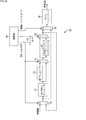
- FIG. 4 It is a block diagram which shows the structural example of the encoding apparatus which produces
- FIG. 18 is a block diagram illustrating a configuration example of an embodiment of a computer to which the present technology is applied.
- LDPC code (hereinafter referred to as a DVB-Like LDPC code) in which parity bits of an LDPC code compliant with DVB-S.2 etc. are interleaved with other parity bit positions. ) And LDPC codes in the format proposed by CRC / ETRI (hereinafter referred to as ETRI format LDPC codes) are being adopted, and an encoding device that supports both formats is desired. Yes.
- LDPC code is a linear code and does not necessarily need to be binary, but here it will be described as being binary.
- the LDPC code is characterized in that the parity check matrix defining the LDPC code is sparse.
- the sparse matrix is configured so that the number of “1” of the matrix components is very small.
- H such a check matrix H is as follows: For example, as shown in FIG. 1, the hamming weight (number of “1” s) (weight) of each column is “3”, and the hamming weight of each row is “6”.
- the LDPC code defined by the check matrix H in which the Hamming weight of each row and each column is constant is referred to as a regular LDPC code.
- an LDPC code defined by a parity check matrix H in which the Hamming weight of each row and each column is not constant is referred to as an irregular LDPC code.
- Such encoding into an LDPC code is realized by generating a generator matrix G based on the check matrix H and generating a codeword by multiplying the binary information word i by the generator matrix G. Is done.
- the generation matrix G is a k ⁇ n matrix (a matrix of k rows and n columns)
- the check matrix H is a matrix of nk rows and n columns.
- the parity check matrix H of nk rows and n columns is used.
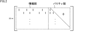
- the portion of nk rows and k columns corresponding to the k-bit information word i in the n-bit code word c is referred to as the information portion, and the portion of the nk rows and nk columns corresponding to the nk-bit parity bit p is the parity portion. That is, if the parity part is a lower triangular matrix or an upper triangular matrix, encoding of the information word i into the LDPC code can be performed using the check matrix H.
- the parity check matrix H is composed of an information part and a parity part of a lower triangular matrix, as shown in FIG.
- the 0th bit of the parity bit p of the word c is the EXOR (exclusive OR) of the bits corresponding to the elements that are 1 in the 0th row of the information part of the parity check matrix H of the information word i. Calculated value.
- the first bit of the parity bit p of the code word c is the bit corresponding to the element that is 1 in the first row of the information part of the parity check matrix H of the information word i and the parity bit p. This is the value obtained by calculating the EXOR of the 0th bit.
- the second bit of the parity bit p of the code word c includes the bit corresponding to the element that is 1 in the second row of the information part of the check matrix H of the information word i, and the parity bit p. This is the value obtained by calculating the EXOR of the 0th and 1st bits.
- the m-th bit of the parity bit p of the code word c is the bit corresponding to the element that is 1 in the m-th row of the information part of the parity check matrix H of the information word i, This is a value obtained by calculating EXOR of the 0th to m ⁇ 1th bits of the parity bit p.
- an n-k code word c can be obtained by obtaining n-k parity bits p and arranging them after a k-bit information word i.
- the parity check section generalizes the lower triangular matrix check matrix H as shown in FIG. 3, the information word i is encoded into the LDPC code as follows using the check matrix H.
- the components of the 0th row (uppermost row) of the parity check matrix H are h 0,0 , h 0,1 ,..., H 0, k in order from the 0th column (leftmost column). ⁇ 1 , and the parity part is 1, 0,... 0.
- the information part is h 1,0 , h 1,1 ,..., H 1, k ⁇ 1 in order from the 0th column
- the parity part is h 1, k , 1.
- the components of the nk-1 row (bottom row) have the information parts h nk-1,0 , h nk-1,1 ,..., H nk- in order from the 0th column. 1, k ⁇ 1 , and the parity part is h nk ⁇ 1, k ,..., H nk ⁇ 1, n ⁇ 2 , 1.
- the k-bit information word i is represented as i 0 , i 1 ,..., I k ⁇ 1
- the nk bit parity bit p is represented as p 0 , p 1
- the code word c is represented by i 0 , i 1 ,..., I k ⁇ 1 , p 0 , p 1 ,. Since the exclusive OR of the product of the codeword c and each row of the check matrix H is 0, the operation of the product of the codeword c and the 0th row of the check matrix H is expressed by the following equation (1).
- parity bit p 0 is expressed by the following equation (2).
- parity bit p 1 is expressed by the following equation (4).
- parity bit p nk-1 is expressed by the following equation (6).
- the parity bit p 0 of nk bits, p 1, ⁇ , p nk -1 look, i 0, i 1 is a k-bit information word i, ⁇ , i k-1
- An n-bit code word c can be obtained by arranging the sequel to.
- one bit can be represented by ⁇ 0,..., Q ⁇ (q ⁇ 1), and is not necessarily binary. Below, it demonstrates as what is binary.
- FIG. 4 shows an example of a parity check matrix H used for LDPC encoding.
- a codeword c codeword 2/3, code length 108
- Is a matrix.
- 0 is represented by “.”.
- the parity check matrix H in FIG. 4 is expressed with an interval in units of 6 ⁇ 6 matrices.
- the information part is multiplied by the information word i of the code word c of the LDPC code
- the parity part is multiplied by the parity bit p of the code word c.
- each row of the information part corresponding to the information word i of the LDPC code is composed of seven “1” s and 101 “0s”.
- the parity part is a matrix having a lower triangular structure (lower triangular matrix). That is, the parity part of the parity check matrix H in FIG. 4 is a matrix in which the upper right corner of the diagonal line of the matrix is all “0”, and has a lower triangular structure.
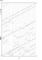
- 5 and 6 show a parity check matrix H ′ after row replacement or column replacement of the parity check matrix H of FIG.
- unit matrix Two or more of a unit matrix or a quasi-unit matrix (hereinafter referred to as a shift matrix), a unit matrix, a quasi-unit matrix, or a shift matrix. It can be represented by a combination of (a plurality of) sums (hereinafter referred to as sum matrix as appropriate) and a P ⁇ P 0 matrix.
- the P ⁇ P unit matrix, the quasi-unit matrix, the shift matrix, the sum matrix, and the zero matrix are hereinafter referred to as constituent matrices as appropriate.
- parity check matrix H in FIG. 4 is the 0th row, (n 0 ⁇ k 0 ) ⁇ v + w (0 ⁇ v ⁇ P ⁇ 1, 0 ⁇ w ⁇ n 0 ) of parity check matrix H. -k 0 -1)
- the row of the row is the P ⁇ w + v row in the parity check matrix H ′ of FIGS.
- the sum of each row of the information part of the parity check matrix H ′, which is an operation necessary for LDPC encoding, and the information word i is calculated as an information word. This can be done by cyclically shifting i in units of six.
- 7A to 7B show parity parts of the parity check matrix H in FIG. 4 and the parity check matrix H ′ in FIGS. 5 and 6.
- the parity part of the parity check matrix H in FIG. 4 is a matrix in which the upper right corner of the diagonal of the matrix is all “0”, and has a lower triangular structure.
- the diagonal component of the lower triangular matrix and the component immediately below the component are 1, and the other components are 0.
- FIG. 8 is a block diagram illustrating a configuration example of the encoding apparatus 1 that generates the above-described LDPC code.
- the encoding device 1 includes a bit width adjustment circuit 11, a cyclic shift circuit 12, an adder 13, a RAM 14, an interleaver 15, an accumulator 16, a selector 17, and a control unit 18.
- An information word D11 (information word i) is supplied to the bit width adjustment circuit 11 in units of 2 bits, and the bit width adjustment circuit 11 combines three information words D11 supplied in units of 2 bits to form a unit of 6 bits. Is supplied to the cyclic shift circuit 12 as the information word D12.
- the information part 1 of the parity check matrix H ′ corresponding to the information word D12 is cyclically shifted from the control part 18 by a number of cyclic shifts of the original unit matrix in the parity check matrix H ′.
- a control signal D21 representing such information is supplied.
- the product (h ⁇ i) of the value h of each row of the non-zero matrix and the information word D12 is obtained and supplied (output) to the adder 13 in sequence.
- the cyclic shift circuit 12 converts the sum matrix into a plurality of matrixes of a unit matrix, a quasi-unit matrix, or a shift matrix.
- the product of the matrix and the information word D12 is obtained in units of the matrix when it is decomposed into the sum of, and the value obtained by performing EXOR operation (addition) for each corresponding row is supplied to the adder 13 as the information word D13.
- the adder 13 is composed of six adders (not shown), and each adder performs EXOR of the 6-bit product D13 from the cyclic shift circuit 12 and the 6-bit sum D14 from the RAM 14 on a bit-by-bit basis. And a 6-bit value obtained as a result is supplied to the RAM 14 as a sum D15 (first integrated value), whereby the product D13 is integrated line by line in units of six lines.
- the RAM 14 is supplied with a control signal D22 for designating an address for reading or writing data from the control unit 18. Based on the control signal D22, the RAM 14 stores the sum D15 from the adder 13 in units of 6 bits, or reads the already stored sum D15 in units of 6 bits or 2 bits.
- the RAM 14 can simultaneously store or read out the sum D15 of 6 bits or 2 bits, the processing in the LDPC encoding can be performed in units of 6 bits or 2 bits.
- the encoding apparatus 1 can perform LDPC encoding with an appropriate circuit scale and operating frequency.
- Interleaver 15 controls the order of sum D16 supplied from RAM 14. Specifically, the interleaver 15 rearranges the sum D16 in the order corresponding to the check matrix H, and supplies the rearranged sum D17 to the accumulator 16.
- the accumulator 16 is supplied from the control unit 18 with a selection signal D23 indicating selection in the selector 62 (FIG. 14 to be described later) of the accumulator 16, and the accumulator 16 is the sum supplied from the selection signal D23 and the interleaver 15 sequentially.
- a predetermined operation for example, equations (2), (4), (6)
- the resulting parity bit p is sequentially supplied to the selector 17 as a parity bit D18 in units of 2 bits ( Output. That is, the accumulator 16 integrates the sum D17 and supplies the resulting parity bit p to the selector 17 as a parity bit D18 (second integrated value) in units of 2 bits.
- the selector 17 is supplied with the information word i delayed for a predetermined time as the information word D19 in units of 2 bits.
- the selector 17 selects either one of the parity bit D18 and the information word D19 from the accumulator 16 based on the selection signal D24 indicating the selection of either the parity bit D18 or the information word D19 from the control unit 18.
- the control unit 18 supplies the control signal D21 to the cyclic shift circuit 12, the control signal D22 to the RAM 14, the selection signal D23 to the accumulator 16, and the selection signal D24 to the selector 17.
- the (6 ⁇ s) to (6 ⁇ (s + 1) ⁇ 1) -th bit (s 0, 1, 2,8) Of the information word i supplied from the bit width adjustment circuit 11.
- the information word D12 of k 0 -1) is called the s-th vector.
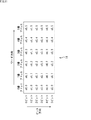
- the numbers on the top row represent the vector numbers, and the numbers on the left end represent the numbers from the top of the constituent matrix of the check matrix H ′. Note that numbers from the top of the configuration matrix are assigned in order from 0.
- “ ⁇ ” indicates that the cyclic shift circuit 12 does not output the information word D13.
- the constituent matrix from (0, 0) to (5, 5) of the check matrix H ′ is a unit matrix.
- (6,0) to (11,5) are composed of a sum matrix (a first shift matrix obtained by cyclically shifting a 6 ⁇ 6 unit matrix by two in the right direction and only four in the right direction.
- the cyclic shift circuit 12 first does not perform the cyclic shift according to the constituent matrix constituting the 0th to 5th columns from the left of the parity check matrix H ′, and performs the 0th vector and the parity check matrix H ′.
- the 0th vector is output as it is as the product D13. That is, as shown in FIG. 9, when the product of the 0th vector and the 0th component matrix from the top of the check matrix H ′ is obtained, the cyclic shift amount of the cyclic shift circuit 12 is zero.
- the cyclic shift circuit 12 cyclically shifts the 0th vector by two in the right direction, and cyclically shifts the 0th vector by four in the right direction, and two cyclic shifts obtained as a result.
- the product of the zeroth vector and the component matrix of (6, 0) to (11, 5) is obtained by performing an EXOR operation on the subsequent 6-bit information word D12.
- the cyclic shift circuit 12 receives the information word obtained for each of the first and second shift matrices so that the information word D12 obtained in this way is stored in the same address of the RAM 14 via the adder 13. Exor D12. Then, the cyclic shift circuit 12 outputs the obtained product as a product D13.
- the cyclic shift amount of the cyclic shift circuit 12 is 4 times in the right direction. Times.
- the cyclic shift circuit 12 since the second (12,0) to (17,5) component matrix from the top of the check matrix H ′ is a zero matrix, the cyclic shift circuit 12 does not perform any processing on the component matrix. No operation is performed and nothing is output (“ ⁇ ” in FIG. 9).
- the cyclic shift circuit 12 cyclically shifts the 0th vector three times in the right direction, so that the 0th vector and the third (18,0) of the check matrix H ′ (23, Obtain the product of the component matrix of 5) and cyclically shift the 0th vector to the left five times to obtain the product of the 0th vector and the component matrix of (30,0) to (35,5) . Then, the cyclic shift circuit 12 outputs the information word D12 after the cyclic shift as a product D13.
- the cyclic shift circuit 12 calculates the product of the 1st to 11th vectors supplied from the bit width adjustment circuit 11 for the 2nd to 12th times and the 6th to 71st columns from the left of the check matrix H ′, respectively. Ask.
- the word direction of the RAM 14 used in the following description is the horizontal direction in the figure, and is referred to as address 0, address 1, address 2,...
- the bit direction of the RAM 14 is the vertical direction in the figure, and is referred to as the 0th bit, the 1st bit, the 2nd bit,.
- the product of the 0th vector and the 0th component matrix from the top of the check matrix H ′ is supplied to the RAM 14 from the cyclic shift circuit 12 via the adder 13 as a 6-bit sum D15.
- the RAM 14 stores each bit of the sum D15 in order from the 0th bit of the 0th address.
- the product of the first vector and the first constituent matrix from the top of the check matrix H ′ is supplied from the cyclic shift circuit 12 to the RAM 14 via the adder 13 as a 6-bit sum D15.
- the RAM 14 reads the product of the 0th vector stored in the 0th to 5th bits of the 0th address and the 0th component matrix from the top of the check matrix H ′, and adds the adder 13 as a 6-bit sum D14. To supply. Thereafter, similarly, the 6-bit sum D15 stored in the first to fifth addresses of the RAM 14 is read out and supplied to the adder 13 as the sum D14.
- the adder 13 is a product of the 0th vector supplied from the RAM 14 as a 6-bit sum D14 and the 0th component matrix from the top of the check matrix H ′, and the 1st vector supplied from the cyclic shift circuit 12.
- An EXOR operation is performed on the product of the check matrix H ′ and the 0th component matrix from the top, and the resulting sum D15 is supplied to the RAM.
- the RAM 14 stores each bit of the sum D15 in order from the 0th bit of the 0th address. That is, the RAM 14 updates the 0th address. Thereafter, the RAM 14 updates the 1st to 5th addresses in the same manner.
- the 0th bit of the 0th address of the RAM 14 is the product of the 0th row from the top of the parity check matrix H ′ and the 0th to 11th vectors. Is stored, which is the sum D15 of o 0,0 . Further, o 1,0, to o 5,0 are stored in the 1st to 5th bits of the 0th address of the RAM 14, respectively.
- the address of the RAM 14 corresponds to the six rows of the information part of the parity check matrix H, and the RAM 14 moves from above the parity check matrix H ′ corresponding to the sum D15 from the upper left to the lower right in the figure.
- the sum D15 (o 0,0 to o 5,5 ) is stored so that the number of rows (6 ⁇ v + w) increases.
- the RAM 14 stores (stores) o 0,0 to o 5,5 so that 1 of the constituent matrix of the check matrix H ′ is packed in the column direction (horizontal direction).
- the order in the direction (lateral direction) is (n 0 -k 0 ) ⁇ y + x.
- the order in the bit direction is such that the fifth bit after each number address is the 0th bit of the address on the right (the address of the next number).
- the order in the word direction is such that the next address of the 5th address of each bit is the 0th address of the immediately lower bit (next bit).
- the sum D15 having the sixth order in the bit direction is o 0,1
- the sum D15 having the sixth order in the word direction is o 1,0 .
- the (n 0 ⁇ k 0 ) ⁇ v + w row of the parity check matrix H is the P ⁇ w + v row in the parity check matrix H ′ of FIG. That is, the row of the P ⁇ w + v row of the parity check matrix H ′ is the row of the (n 0 ⁇ k 0 ) ⁇ v + w row of the parity check matrix H.
- the interleaver 15 since the RAM 14 generally cannot simultaneously access two or more addresses, the sum D15 cannot be read in the word direction. Therefore, in the encoding device 1, the order of the sum D15 read by the RAM 14 in the bit direction is changed by the interleaver 15. Details of the interleaver 15 will be described with reference to FIGS. 12 and 13 described later.
- FIG. 12 is a diagram illustrating a detailed configuration example of the interleaver 15 of FIG.
- the interleaver 15 in FIG. 12 is supplied from the five registers 41-1 to 41-5, the five registers 42-1 to 42-5, and the selector 43.
- the interleaver 15 is supplied with a 2-bit sum D16 from the RAM 14, and 1 bit of the sum is stored in the registers 41-1 to 41-5 as a sum D41 in units of 1 bit.
- the other 1 bit is stored as a sum D42 in the registers 42-1 to 42-5 in order of 1 bit.
- the registers 41-1 through 41-5 and the registers 42-1 through 42-5 supply the stored one-bit sum D41 or D42 to the selector 43, respectively.
- the selector 43 selects any two sums D41 or D42 out of the five sums D41 or D42 supplied from the registers 41-1 to 41-5 and the registers 42-1 to 42-5, respectively, and the sum D43. And output as D44.
- the 1-bit sums D43 and D44 are combined and supplied to the accumulator 16 as a 2-bit sum D17.
- the registers 41-1 to 41-5 and the registers 42-1 to 42-5 store the input sum D16 (sum D41 or D42), and the selector 43 By selecting the sum D16 stored in 41-1 through 41-5 and the registers 42-1 through 42-5 and outputting as the sum D17 (sum D43 or D44), the sum D16 input is output. Change the order of sum D17.
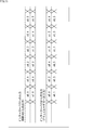
- FIG. 13 it is a timing chart explaining the input / output of data in the interleaver 15 of FIG.
- the horizontal axis represents time.
- the RAM 14 reads out two bits of o 0,0 and o 1,0 stored at the 0th address as a sum D16 and outputs it to the interleaver 15. That is, o 0,0, and o 1,0 are input to the interleaver 15 as the sum D16.
- the RAM 14 outputs the two bits o 0,1, and o 1,1 stored at the first address to the interleaver 15 as a sum D16. Thereafter, in the same manner, the RAM 14 stores o 0,2, and o 1,2 , o 0,3, o 1,3 , o 0,4, and o 1, stored at addresses 2-5 . 4 or o 0,5 and o 1,5 are output to the interleaver 15 as the sum D16.
- the registers 41-1 to 41-5 of the interleaver 15 in FIG. 12 are sequentially supplied with o 0,0 to o 0,5 that are one bit of the sum D16 input to the interleaver 15, Remembered. Further, the other 1 bits o 1,0 to o 5,0 are sequentially supplied to and stored in the registers 42-1 to 42-5. Then, the registers 41-1 to 41-5 and 42-1 to 42-5 supply o 0,0 to o 0,5 and o 1,0 to o 5,0 to the selector 43, respectively.
- the selector 43 first selects o 0,0 and o 0,1 and outputs them as sums D43 and D44, respectively. That is, o 0,0 and o 0,1 are input to the accumulator 16 as the sum D17. Next, the selector 43 selects o 0,2 and o 0,3 and outputs them as sums D43 and D44, respectively. After that, the selector 43 selects o 0,4 and o 0,5 , o 1,0 and o 1,1 , o 1,2 and o 1,3 , o 1,4 and o 1,5 in this order. Output.
- sequence # 1 o 0,0 to o 0,5 stored in the 0th bit of the RAM 14 which is 1 bit of the sum D16 input to the interleaver 15
- sequence # 2 the other 14 bits of the RAM 14
- the selector 43 selects sequence # 1 by 2 bits in order from o 0,0 and then selects sequence # 2 as o.
- the interleaver 15 selects the 2-bit sum D16 that is read out in the bit direction order of the RAM 14 and is input by 2 bits in the word direction order of the RAM 14 in which the sum D16 is stored.
- Ow, v which is the sum of products of each row of the information part of the parity check matrix H and each of the 0th to 11th vectors, is sequentially 2 bits from the 0th row of the information part of the parity check matrix H.
- FIG. 14 shows a detailed configuration example of the accumulator 16 of FIG.
- the adder 61 is supplied with a sum D61, which is one bit of the 2-bit sum D17, from the interleaver 15 and a parity bit D65 obtained as a result of the previous addition from the adder 63.
- the adder 61 adds the sum D61 and the parity bit D65, and supplies the resulting value to the selector 62 as a sum D63.
- the selector 62 is supplied with a sum D61 and a selection signal D23 from the controller 18.
- the selector 62 uses the sum D61 or D63 as a parity bit D64 based on the selection signal D23, and an adder with the selector 17 To 63.
- the adder 63 is supplied with a sum D62 which is one bit other than the sum D61 of the two-bit sum D17 from the interleaver 15.
- the adder 63 adds the parity bit D64 obtained as a result of the previous addition supplied from the selector 62 and the sum D62, and outputs the resultant value to the selector 17 and the adder 61 as a parity bit D65.
- the parity bits D64 and D65 output from the selector 62 and the adder 63 are combined and supplied to the selector 17 as a 2-bit parity bit D18 (parity bit p).
- the accumulator 16 of FIG. 14, o 0,0 and o 2 sum of bit D17 0,1 is supplied from the interleaver 15, o 0,0 is a sum D61 to the adder 61 and the selector 62 Then, o 0,1 is supplied to the adder 63 as a sum D62. At this time, since addition by the adder 63 has not been performed yet, the parity bit D65 is not supplied to the adder 61, and the adder 63 supplies the sum D61 as it is to the selector 62 as the sum D63.
- the selector 62 selects the sum D61 (in this case, o 0,0 ) from the interleaver 15 based on the selection signal D23, and sends it to the selector 17 and the adder 63 as a parity bit D64 (in this case, p 0 ). Output.
- the adder 63 adds the sum D62 from the interleaver 15 (in this case, o 0,1 ) and the parity bit D64 from the selector 62, and obtains a value (in this case, o 0,1). + p 0 ) is output to the selector 17 and the adder 61 as the parity bit D65 (in this case, p 1 ).
- the parity bits D64 and D65 are combined and output to the selector 17 and the adder 61 as a 2-bit parity bit D18.
- the accumulator 16 calculates the parity bits p 2 to p nk-1 two bits at a time according to the equations shown in FIGS. 15 and 16, and outputs the result as the parity bit D18.
- This encoding process is started, for example, when the information word D11 (information word i) is input in units of 2 bits.
- step S1 the bit width adjustment circuit 11 sets the vector number s of the information word D12 output to the cyclic shift circuit 12 to 0, and proceeds to step S2.
- step S2 the bit width adjustment circuit 11 combines the information word D11 input in units of 2 bits into 6 bits, and supplies it to the cyclic shift circuit 12 as the s-th vector (information word D12).
- step S2 the process proceeds to step S3, where the cyclic shift circuit 12 cyclically shifts the s-th vector based on the control signal D21 from the control unit 18, thereby changing the information part of the parity check matrix H ′.
- a product (h ⁇ i) of the value h and the s-th vector of each row of the constituent matrix that is not the zero matrix among the constituent matrices to be configured is obtained and supplied to the adder 13 as a 6-bit product D13.
- step S3 the process proceeds to step S4, where the adder 13 exclusively uses the 6-bit product D13 from the cyclic shift circuit 12 and the 6-bit sum D14 supplied from the RAM 14 in step S5 described later. A logical sum is obtained for each bit, and a 6-bit value obtained as a result is supplied to the RAM 14 as a sum D15.
- the adder 13 supplies the product D13 as it is to the RAM 14 as the sum D15.
- step S4 the process proceeds to step S5, where the RAM 14 stores the sum D15 from the adder 13 in units of 6 bits based on the control signal D22 from the control unit 18.
- the RAM 14 reads the already stored sum D15 in units of 6 bits or 2 bits.
- the RAM 14 supplies the sum D15 read in units of 6 bits to the adder 13 as a sum D14, or supplies the sum D15 read in units of 2 bits to the interleaver 15 as a sum D16.
- step S5 the process proceeds to step S6, where the bit width adjustment circuit 11 determines whether the vector number s is smaller than 11, and if it is smaller than 11, the process proceeds to step S7.
- step S7 the bit width adjustment circuit 11 increments the vector number s by 1, returns to step S2, and repeats the above-described processing.
- step S6 when it is determined in step S6 that the vector number s is not smaller than 11 (11 or more), the process proceeds to step S8, and the interleaver 15 calculates the sum D16 supplied from the RAM 14 in step S5.
- the data is rearranged in the order corresponding to the check matrix H, and the sum D17 after the rearrangement is supplied to the accumulator 16.
- step S8 the process proceeds to step S9, where the accumulator 16 performs a predetermined calculation using the sum D17 from the interleaver 15, and the resulting parity bit p is set as a parity bit D18 in units of 2 bits.
- the data is supplied to the selector 17, and the process proceeds to step S10.
- step S10 the selector 17 outputs all of the information word D19 delayed and input in units of 2 bits as a code word D20, and then in step S9 outputs the parity bit D18 supplied from the accumulator 16 in units of 2 bits. By outputting as D20, the code word c is output and the process is terminated.
- the adder 13 performs the product of the 6-bit information word D12 and the information part of the parity check matrix H corresponding to the information word D12 in units of 6 bits. And the sum D15 obtained as a result is stored in the RAM 14, and the accumulator 16 sums the sum D17 corresponding to the 2-bit sum D16 (D15) read from the RAM 14, and the resulting two bits. Since the parity bit D18 is output as the parity bit p of the code word c of the LDPC code, the circuit scale of the encoding device can be reduced without changing the operation speed of linear code encoding.
- the number of columns k of the information part of the parity check matrix H is 102, and the number of rows (or the number of columns) P of the constituent matrix is 6.
- the number of columns k of the information part and the number of rows P of the constituent matrix are It is not limited to.
- the encoding apparatus 1 can be applied to a check matrix H in which the information length of the information word i is larger than 102 and the number of columns of the information part is large, and a square matrix larger than 6 ⁇ 6 is divided as a constituent matrix It is also applicable to possible check matrix H.
- the number of bits of the RAM 104 is 2, the number of words is 6, and the number is 3.
- the number of bits, the number of words, and the number are not limited to this, and are assumed to have flexibility.
- the number of bits of the sum D104 that can be simultaneously read from the RAM 104 or the number of bits of the sum D104 that can be written may be any value.
- the LDPC code is assumed to be binary. However, when 1 bit is represented by ⁇ 0,..., Q ⁇ (q> 1) instead of binary, the parity bit p by the accumulator 16 is used. This calculation also requires multiplication and division.
- FIG. 18 is a diagram again illustrating a parity check matrix H used for LDPC encoding in the encoding device 1 of FIG. 8.
- the information length K and parity length M for an LDPC code having a certain code length N are determined by the coding rate.
- the parity check matrix H is a matrix in which rows ⁇ columns are M ⁇ N (a matrix having M rows and N columns).
- the information matrix corresponding to the information bits of the parity check matrix H (information portion in FIG. 2) is A matrix and the parity matrix corresponding to the parity bits (parity portion in FIG. 2) is B matrix
- the information matrix A matrix is An M ⁇ K matrix
- a parity matrix B matrix is an M ⁇ M matrix.
- Standards such as DVB-T.2 specify LDPC codes with code length N of 64800 bits and 16200 bits.
- the DVB-Like LDPC code is an LDPC code obtained by interleaving (parity interleaving) the parity bits of the LDPC code generated by the encoding device 1 in FIG. 8 at the positions of other parity bits.
- IRA International Repeat Accumulate
- the parity matrix (B matrix) of the parity check matrix H used in the LDPC encoding of the encoding device 1 in FIG. 8 has a staircase structure as shown in FIG.
- the B matrix (parity matrix) of the check matrix H is a matrix having a staircase structure (lower1bidiagonal matrix) in which 1 elements are arranged in steps.
- the row weight of the parity matrix is 1 for the first row and 2 for all the remaining rows.
- the column weight is 1 for the last column and 2 for all the remaining columns.
- the LDPC code of the parity check matrix H in which the parity matrix (B matrix) has a staircase structure can be easily generated using the parity check matrix H.
- FIG. 20 is a diagram illustrating a parity matrix of the parity check matrix H corresponding to the LDPC code after parity interleaving.
- the information matrix (example A row) of the check matrix H corresponding to the LDPC code output from the encoding device 1 in FIG. 8 is the check corresponding to the LDPC code defined in the standard such as DVB-T.2. Similar to the information matrix of the matrix H, it has a cyclic structure.
- a cyclic structure is a structure in which a column matches a cyclic shift of another column.For example, for each P column, the position of 1 in each row of the P column is the first of the P column.
- a structure in which the column is cyclically shifted in the column direction by a predetermined value such as a value proportional to the value q obtained by dividing the parity length M is also included.
- the P row in the cyclic structure is referred to as a unit size as appropriate.
- the unit size P is defined as 360 which is one of the divisors of the parity length M except 1 and M.
- a parity interleaver that performs parity interleaving of the LDPC code sets the information length to K and sets an integer between 0 and less than P to x and 0 Assuming that an integer less than q is y, the parity bit is interleaved, and the K + qx + y + 1-th code bit of the N-bit LDPC code bit is replaced with the K + Py + x + 1-th code bit. Interleave at the position.
- the K + qx + y + 1-th code bit and the K + Py + x + 1-th code bit are both the K + 1-th code bit and the subsequent parity bits, and are therefore parity bits. According to interleaving, the position of the parity bit of the LDPC code is moved.
- Such parity interleaving can improve the tolerance to burst errors.
- the LDPC code after parity interleaving that interleaves the K + qx + y + 1-th code bit at the position of the K + Py + x + 1-th code bit is K + qx + of the original parity check matrix H.
- the pseudo cyclic structure means a structure in which a part except for a part has a cyclic structure.
- the parity check matrix obtained by performing column replacement equivalent to parity interleaving on the parity check matrix of the LDPC code specified in the DVB-T.2 standard, etc. is 360 rows ⁇
- the 360-column part (shift matrix) there is only one element of 1 (it is an element of 0), and in that respect, it is not a (perfect) cyclic structure, but a pseudo cyclic structure. .
- the conversion parity check matrix for the LDPC code parity check matrix output from the encoding apparatus 1 in FIG. 8 is, for example, similar to the conversion parity check matrix for the LDPC code parity check matrix defined in the DVB-T.2 standard and the like. It has a cyclic structure.
- the conversion check matrix in FIG. 20 replaces rows so that the conversion check matrix is configured with a configuration matrix described later. (Row replacement) is also applied to the matrix.
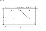
- FIG. 21 is a diagram showing the structure of a check matrix H in the ETRI format.
- the ETRI format check matrix H is composed of A matrix, B matrix, C matrix, D matrix, and Z matrix.
- the A matrix is the same as the information matrix of the parity check matrix H of the LDPC code shown in FIG.
- the B matrix is a matrix with a staircase structure adjacent to the right of the A matrix, with g rows and g columns.
- the B matrix is the same as the parity matrix of the parity check matrix H of the LDPC code shown in FIG.
- the C matrix is a matrix adjacent to the N-K-g rows and K + g columns below the A matrix and the B matrix.
- the D matrix is an N-K-g row N-K-g column unit matrix adjacent to the right of the C matrix.
- the Z matrix is a zero matrix (0 matrix) adjacent to the right of the B matrix with g rows and N-K-g columns.
- the A matrix and the C matrix have a cyclic structure for every 360 columns (unit size P), similar to the information matrix of the check matrix of the DVB-Like LDPC code.
- the ETRI format LDPC code is an LDPC code obtained by interleaving (parity interleaving) parity bits corresponding to the B matrix and D matrix of the LDPC code LDPC-encoded using the ETRI format check matrix H.
- the parity check matrix H in ETRI format has the same A matrix and B matrix as the parity check matrix H used for LDPC encoding of DVB-Like ⁇ LDPC codes, and the Z matrix is a zero matrix. Therefore, the ETRI format LDPC code can be generated by two-stage LDPC encoding as follows.
- LDPC encoding is performed using A
- the encoding apparatus uses the generated DVB-Like LDPC code as LDPC target data, and becomes a difference between the DVB-Like LDPC code parity check matrix H (FIG. 18) and the ETRI format parity check matrix H (FIG. 21).
- LDPC encoding using the second check matrix H CD [C
- DVB-Like LDPC code format is simply referred to as DVB-Like format
- ETRI format LDPC code format is also simply referred to as ETRI format.
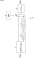
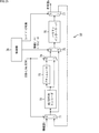
- FIG. 22 is a block diagram illustrating a configuration example of the first embodiment of an encoding device employing the present technology.
- AB matrix encoder 51 includes an AB matrix encoder 51, a B matrix parity interleaver 52, a CD matrix encoder 53, a selector 54, a parity interleaver 55, and a control unit 56.
- the information word i is input to the encoding device 50, and the encoding device 50 performs LDPC encoding on the input information word i in either DVB-Like format or ETRI format, and the resulting code word c is output.
- the codeword c output from the encoding device 50 is different from the codeword c output from the encoding device 1 of FIG.
- the AB matrix encoder 51 has the same configuration as that of the encoding device 1 in FIG. 8, and the LDPC target data is, for example, DVB-S.2, DVB-T.2, DVB-C.
- LDPC encoding is performed to encode the LDPC code (corresponding to the check matrix) specified in a predetermined standard such as .2 and the resulting LDPC code is output.
- the LDPC code output from the AB matrix encoder 51 for the information word i input as LDPC target data is represented by i + p B.
- the B matrix parity interleaver 52 performs parity interleaving for interleaving the parity bit p B of the LDPC code i + p B generated by the AB matrix encoder 51 to the position of another parity bit, and the LDPC code after the parity interleaving is This is supplied to the CD matrix encoder 53.
- the LDPC code after parity interleaving by the B matrix parity interleaver 52 is represented by i + p B ′.
- FIG. 23 is a block diagram showing a detailed configuration example of the CD matrix encoder 53.
- the CD matrix encoder 53 can be realized by a configuration in which the accumulator 16 is omitted in the encoding device 1 shown in FIG.
- the CD matrix encoder 53 regards the LDPC code i + p B ′ supplied from the B matrix parity interleaver 52 as the input information word i in the encoding device 1 of FIG. 8 and uses the second check matrix H CD . Perform LDPC encoding. However, the accumulation process of the accumulator 16 in the encoding device 1 of FIG. 8 is not executed.
- the CD matrix encoder 53 outputs an LDPC code obtained as a result of LDPC encoding using the second parity check matrix H CD .
- the LDPC code output from the CD matrix encoder 53 is represented by i + p B ′ + p D.
- the selector 54 selects one of the two inputs under the control of the control unit 56 and outputs it to the parity interleaver 55 in the subsequent stage. Specifically, the selector 54 selects the input from the AB matrix encoder 51 when a “0” select control signal corresponding to DVB-Like format encoding is supplied from the control unit 56. When a “1” select control signal corresponding to ETRI format encoding is supplied to the parity interleaver 55, the input from the CD matrix encoder 53 is selected and output to the parity interleaver 55.
- the selector 54 selects the LDPC code i + p B from the AB matrix encoder 51 when a “0” select control signal corresponding to DVB-Like format encoding is supplied from the control unit 56.
- the select control signal “1” corresponding to ETRI format encoding is supplied to the parity interleaver 55, the LDPC code i + p B ′ + p D from the CD matrix encoder 53 is selected. Output to the parity interleaver 55.
- the parity interleaver 55 performs parity interleaving for interleaving the parity bits of the LDPC code to the positions of other parity bits.
- the parity interleaver 55 when the LDPC code i + p B corresponding to the DVB-Like format encoding is input from the selector 54, the parity interleaver 55, like the B matrix parity interleaver 52, has the LDPC code i + p. interleaves the parity bits p B of B, after parity interleave of an LDPC code i + p B ', and outputs a codeword c.
- the parity interleaver 55 interleaves the parity bit p D of the LDPC code i + p B ' + p D.
- the LDPC code i + p B '+ p D ' after parity interleaving is output as a code word c.
- the control unit 56 supplies a selector 54 with a select control signal for selecting an input depending on whether the format of the LDPC code to be generated is the DVB-Like format or the ETRI format. More specifically, when the format of the generated LDPC code is the DVB-Like format, the control unit 56 supplies a select control signal representing “0”, and the format of the generated LDPC code is the ETRI format. In this case, a select control signal representing “1” is supplied.
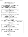
- step S31 the control unit 56 supplies the selector 54 with a select control signal according to whether the format of the LDPC code to be generated is the DVB-Like format or the ETRI format. Note that the processing in this step may be performed until the selection target data is input to the selector 54, and is not necessarily executed at the beginning of the LDPC encoding processing.
- step S32 the AB matrix encoder 51 performs LDPC encoding on the input information word i using the first check matrix H AB .
- the AB matrix encoder 51 outputs an LDPC code i + p B obtained as a result of LDPC encoding.
- parity interleave is performed to interleave the positions of other parity bits.
- This parity interleaving is executed by the parity interleaver 55 when the generated LDPC code format is the DVB-Like format, and when the generated LDPC code format is the ETRI format, the B matrix parity interleaver is executed. 52 is executed.
- the parity interleaver 55 performs parity interleaving for interleaving the parity bit p B of the LDPC code i + p B generated by the AB matrix encoder 51 to the position of another parity bit, and the LDPC code i + p after parity interleaving.
- the LDPC code i + p B ′ after parity interleaving generated by the parity interleaver 55 is output as a code word c.
- the LDPC code i + p B generated by the AB matrix encoder 51 is supplied to the B matrix parity interleaver 52.
- the B matrix parity interleaver 52 performs parity interleaving for interleaving the parity bit p B of the LDPC code i + p B generated by the AB matrix encoder 51 to the position of another parity bit, and the LDPC code i + p B ′ after parity interleaving. Is generated.
- the parity interleaved LDPC code i + p B ′ generated by the B matrix parity interleaver 52 is output to the CD matrix encoder 53.
- step S34 differs depending on whether the format of the LDPC code to be generated is the DVB-Like format or the ETRI format.
- step S34 when the format of the generated LDPC code is the DVB-Like format, the LDPC encoding process of FIG. 24 is terminated.
- step S34 if the format of the LDPC code to be generated is the ETRI format in step S34, the process proceeds to step S35.
- step S35 the CD matrix encoder 53 performs LDPC encoding using the second parity check matrix H CD using the LDPC code i + p B ′ supplied from the B matrix parity interleaver 52 as LDPC target data.
- the CD matrix encoder 53 outputs the LDPC code i + p B '+ p D obtained as a result of LDPC encoding to the parity interleaver 55 via the selector 54.
- step S36 the parity interleaver 55 'interleaves the parity bits p D of + p D, parity LDPC code i + p B after interleaving' LDPC code i + p B outputted from the CD matrix encoder 53 a + p D ', the code word c, and the LDPC encoding process in FIG. 24 is terminated.
- the LDPC code corresponding to the format is converted. Can be generated.
- both DVB-Like LDPC code and ETRI format LDPC code can be supported.
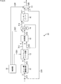
- FIG. 25 is a block diagram illustrating a configuration example of the second embodiment of an encoding device employing the present technology.
- 25 includes a selector 71, an AB / CD matrix encoder 72, an accumulator 73, selectors 74 and 75, a parity interleaver 76, a selector 77, and a control unit 78.
- the selector 71 selects one of the two inputs under the control of the control unit 78 and outputs it to the AB / CD matrix encoder 72 and the selector 75 in the subsequent stage. Specifically, the selector 71 selects an input from outside the device when a first select control signal of “0” corresponding to DVB-Like format encoding is supplied from the control unit 78. Output to the AB / CD matrix encoder 72 and the selector 75. On the other hand, when the first select control signal “1” corresponding to ETRI format encoding is supplied, the selector 71 selects the information fed back from the selector 77 to select the AB / CD matrix encoder 72 and the selector. Output to 75.
- the AB / CD matrix encoder 72 is configured in the same manner as the CD matrix encoder 53 of the first embodiment shown in FIG.
- the AB / CD matrix encoder 72 includes a first check matrix H AB used in LDPC encoding in both DVB-Like format and ETRI format, and a second check matrix H used in LDPC encoding in ETRI format.
- Each CD has a plurality of types in the internal memory corresponding to various coding rates and code lengths N.
- which type of check matrix is used is set by the control unit 78 in conjunction with the first select control signal supplied to the selectors 71 and 74.
- the AB / CD matrix encoder 72 uses the first parity check matrix H AB for the input LDPC target data when the control unit 78 instructs the encoding using the first parity check matrix H AB .
- LDPC encoding On the other hand, when the control unit 78 instructs the encoding using the second parity check matrix H CD , the AB / CD matrix encoder 72 performs the second parity check matrix H CD on the input LDPC target data.
- LDPC encoding is performed using However, since the accumulator 16 is omitted in the AB / CD matrix encoder 72 as in the case of the CD matrix encoder 53 of the first embodiment, the accumulation process of the accumulator 16 in the encoding device 1 in FIG. 8 is not executed. .
- the AB / CD matrix encoder 72 supplies the result of LDPC encoding to the accumulator 73 and the selector 74.
- the accumulator 73 performs the same processing as the accumulator 16 of the encoding device 1 in FIG. That is, the accumulator 73 executes a process of adding parity bits of the LDPC code supplied from the AB / CD matrix encoder 72 and outputs the processing result to the selector 74.
- the selector 74 selects one of the two inputs under the control of the control unit 78 and outputs it to the subsequent selector 75. Specifically, the selector 74 selects the output from the accumulator 73 when the first select control signal of “0” corresponding to the DVB-Like format encoding is supplied from the control unit 78 and selects the selector 75. When the first select control signal “1” corresponding to ETRI format encoding is supplied, the output from the AB / CD matrix encoder 72 is selected and output to the selector 75.
- the selector 75 selects one of the two inputs under the control of the control unit 78 and outputs it to the parity interleaver 76 at the subsequent stage.
- the selector 75 is supplied with a second select control signal corresponding to whether the input data is an information bit or a parity bit.
- the selector 75 selects the output from the selector 71 and outputs it to the parity interleaver 76 when the second select control signal of “1” corresponding to the information bit is supplied from the control unit 78.
- the selector 75 selects the output from the selector 74 and outputs it to the parity interleaver 76.
- the parity interleaver 76 performs the same processing as the parity interleaver 55 in the first embodiment shown in FIG. That is, the parity interleaver 76 performs parity interleaving for interleaving the parity bits of the LDPC code supplied from the selector 75 to the positions of other parity bits.
- the selector 77 selects and outputs one of the two output destinations according to the control of the control unit 78. Specifically, when a third select control signal “0” representing an external output is supplied from the control unit 78, the selector 77 outputs the input data to the outside as a code word c. On the other hand, when the third select control signal “1” representing feedback is supplied from the control unit 78, the selector 77 outputs the input data to the input corresponding to “1” of the selector 71. .
- the control unit 78 supplies the selectors 71 and 74 with a first select control signal of “0” corresponding to DVB-Like format encoding or “1” corresponding to ETRI format encoding.
- control unit 78 supplies the second select control signal corresponding to the information bit or the parity bit to the selector 75. Further, the control unit 78 supplies the selector 77 with a third select control signal of “0” representing external output or “1” representing feedback. In addition, as described above, the control unit 78 appropriately supplies a control signal for controlling the encoding operation to the AB / CD matrix encoder 72 and the like.
- the encoding device 50 according to the second embodiment is configured as described above.
- the B matrix parity interleaver 52 and the parity interleaver 55 according to the first embodiment are shared by one parity interleaver 76, and an AB matrix encoder 51 is used.
- the CD matrix encoder 53 are shared by one AB / CD matrix encoder 72 by providing an accumulator 73 in the subsequent stage.
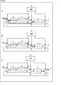
- the control unit 78 supplies the selectors 71 and 74 with a first select control signal of “0” corresponding to the encoding in the DVB-Like format. Then, a third select control signal “0” representing the external output is supplied to the selector 77.
- an information bit (information word) i as LDPC encoding target data is input to the selector 71.
- the information bit i input to the selector 71 is output to the AB / CD matrix encoder 72 and the selector 75.
- the selector 75 is supplied with a second select control signal of “1” corresponding to the information bit from the controller 78.
- the selector 75 outputs the information bit i supplied from the selector 71 to the parity interleaver 76 based on the second select control signal.
- the second select control signal supplied from the controller 78 to the selector 75 is changed to a second select control signal of “0” corresponding to the parity bit.
- the AB / CD matrix encoder 72 to which the information bit i is supplied from the selector 71 executes LDPC encoding using the first check matrix H AB for the information bit i. Then, the accumulator 73 executes the parity bit accumulation process of the LDPC code to generate the LDPC code i + p B.
- the parity interleaver 76 performs parity interleaving for interleaving the parity bit p B of the supplied LDPC code i + p B to the position of another parity bit, and after the parity interleaving.
- the LDPC code i + p B ′ is supplied to the selector 77.
- the selector 77 Since the selector 77 is supplied with the third select control signal “0” representing the external output, the selector 77 outputs the inputted LDPC code i + p B ′ after parity interleaving to the outside as the code word c. To do.
- a DVB-Like LDPC code can be generated and output as described above.
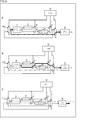
- the process of the first stage when the encoding device 50 generates the ETRI format LDPC code specifically, the LDPC code i + p B is supplied to the parity interleaver 76 described with reference to A and B of FIG.
- the process up to this point is the same as the DVB-Like LDPC code generation.
- parity interleaving is executed by the parity interleaver 76, and the LDPC code i + p B ′ after parity interleaving is generated and output to the selector 77.
- the selector 77 is supplied with a third select control signal “1” representing feedback.
- the selector 77 feeds back the LDPC code i + p B ′ after parity interleaving supplied from the parity interleaver 76 to the selector 71 based on the third select control signal. After the feedback, the third select control signal supplied to the selector 77 is changed to a third select control signal of “0” representing the external output.
- the first select control signal supplied to the selectors 71 and 74 until the LDPC code i + p B ′ after parity interleaving is fed back to the selector 71 is “1” corresponding to ETRI format encoding.
- the first select control signal is changed.
- the second select control signal supplied to the selector 75 is also changed to a second select control signal of “1” corresponding to the information bit.
- the LDPC code i + p B ′ after parity interleaving that has been fed back and input to the selector 71 is output to the AB / CD matrix encoder 72 and the selector 75 as shown in B of FIG.
- the selector 75 is supplied with a second select control signal of “1” corresponding to the information bit from the controller 78. Based on the second select control signal, the selector 75 outputs the parity interleaved LDPC code i + p B ′ supplied from the selector 71 to the parity interleaver 76.
- the second select control signal output from the control unit 78 to the selector 75 is changed to a second select control signal of “0” corresponding to the parity bit.
- the second check matrix H CD is used for the LDPC code i + p B ′ after parity interleaving.
- LDPC encoding is performed to generate an LDPC code i + p B '+ p D.
- the LDPC code i + p B '+ p D generated by the AB / CD matrix encoder 72 is supplied with the first select control signal of “1” corresponding to the ETRI format encoding.
- a selector 75 to which a second select control signal of “0” corresponding to the parity bit is supplied to the parity interleaver 76.
- the parity interleaver 76 'interleaving the parity bits p D of + p D, parity LDPC code i + p B after interleaving' LDPC code i + p B a + p D ', fed to the selector 77 To do.
- the selector 77 Since the selector 77 is supplied with the third select control signal “0” representing the external output, the selector 77 uses the input LDPC code i + p B ′ + p D ′ after parity interleaving as the code word c. Output to the outside.
- the ETRI format LDPC code can be generated and output as described above.
- both DVB-Like LDPC codes and ETRI format LDPC codes can be supported.
- FIG. 28 is a block diagram illustrating a configuration example of the third embodiment of an encoding device employing the present technology.
- the encoding device 50 shown in FIG. 28 includes a selector 71, an AB / CD matrix encoder 72, an accumulator 73, a selector 74, a parity interleaver 76, a B matrix parity interleaver 91, selectors 92 and 93, and a control unit 94. Composed.
- the encoding apparatus 50 converts the B matrix parity interleaver 52 and the parity interleaver 55 according to the first embodiment into one parity interleaver 76.
- the AB matrix encoder 51 and the CD matrix encoder 53 are shared by one AB / CD matrix encoder 72 by providing the accumulator 73 in the subsequent stage.
- the configuration subsequent to the selector 74 is different from that of the second embodiment.
- the B matrix parity interleaver 91 performs the same processing as the B matrix parity interleaver 52 of the first embodiment. That is, the B matrix parity interleaver 91 performs parity interleaving for interleaving the parity bit p B of the LDPC code i + p B at the position of another parity bit, and outputs the LDPC code i + p B ′ after the parity interleaving.
- the selector 92 selects one of the two inputs under the control of the control unit 94 and outputs the selected input to the subsequent selector 93.
- the selector 92 is supplied with a second select control signal that becomes “1” only when the B matrix parity interleaver 91 outputs the execution result of the parity interleaving, and becomes “0” otherwise.
- the selector 93 selects one of the two inputs under the control of the control unit 94 and outputs it to the parity interleaver 76 at the subsequent stage.
- the selector 93 is supplied with a third select control signal corresponding to whether the input data is an information bit or a parity bit.
- the controller 94 supplies the selectors 71 and 74 with a first select control signal “0” corresponding to DVB-Like format encoding or “1” corresponding to ETRI format encoding.
- control unit 94 supplies the selector 92 with a second select control signal corresponding to the output or non-output of the B matrix parity interleaver 91. Further, the control unit 94 supplies a third select control signal corresponding to the information bit or the parity bit to the selector 93.
- the encoding device 50 in the third embodiment is configured as described above.
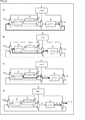
- the control unit 94 supplies the selectors 71 and 74 with a first select control signal of “0” corresponding to encoding in the DVB-Like format. . Further, the control unit 94 supplies a second select control signal of “0” corresponding to the non-output of the B matrix parity interleaver 91 to the selector 92.
- an information bit (information word) i as LDPC encoding target data is input to the selector 71.
- the information bit i input to the selector 71 is output to the AB / CD matrix encoder 72 and the selector 93.
- the selector 93 at this time is supplied with a third select control signal of “1” corresponding to the information bit from the control unit 94.
- the selector 93 outputs the information bit i supplied from the selector 71 to the parity interleaver 76 based on the third select control signal.
- the third select control signal output from the controller 94 to the selector 93 is changed to a third select control signal of “0” corresponding to the parity bit.
- the LDPC code i + p B output from is supplied to the parity interleaver 76.
- the parity interleaver 76 performs parity interleaving for interleaving the parity bit p B of the supplied LDPC code i + p B to the position of another parity bit, and after the parity interleaving.
- LDPC code i + p B ′ is output to the outside as code word c.
- a DVB-Like LDPC code can be generated and output as described above.
- the control unit 78 In the first stage when the encoding apparatus 50 generates an ETRI format LDPC code, the control unit 78 outputs the first select control signal of “0”, which is the same as in the case of DVB-Like format encoding, to the selectors 71 and 74. To supply.
- information bits (information words) i as LDPC encoding target data are input to the selector 71.
- the information bit i input to the selector 71 is output to the AB / CD matrix encoder 72 and the selector 93.
- the selector 93 at this time is supplied with a third select control signal of “1” corresponding to the information bit from the control unit 94.
- the selector 93 outputs the information bit i supplied from the selector 71 to the parity interleaver 76 based on the third select control signal.
- the AB / CD matrix encoder 72 to which the information bit i is supplied from the selector 71 performs LDPC encoding using the first check matrix H AB for the information bit i. Is executed, and the accumulator 73 executes the parity bit accumulation process of the LDPC code to generate the LDPC code i + p B.
- the LDPC code i + p B output from the accumulator 73 is supplied to the B matrix parity interleaver 91.
- the B matrix parity interleaver 91 performs parity interleaving for interleaving the parity bit p B of the LDPC code i + p B output from the accumulator 73 to the position of another parity bit, and obtains the LDPC code i + p B ′ after the parity interleaving. Output to the selector 92.
- the selector 92 is supplied with a second select control signal of “1” corresponding to the output of the B matrix parity interleaver 91 from the control unit 94.
- the selector 92 generates a parity interleave output from the B matrix parity interleaver 91 based on the second select control signal “1” corresponding to the output of the B matrix parity interleaver 91.
- the later LDPC code i + p B ' is selected and output.
- the output destination of the selector 92 is the selector 71 and the selector 93. Since the selector 93 is supplied with the third select control signal “1” corresponding to the information bit, the selector 93 outputs the output of the selector 92. Is not selected.
- the parity interleaved LDPC code i + p B ′ output from the B matrix parity interleaver 91 is fed back to the selector 71 via the selector 92.
- the first select control signal supplied to the selectors 71 and 74 is in the DVB-Like format before the LDPC code i + p B ′ after parity interleaving is fed back to the selector 71 as shown in A of FIG. It is changed from “0” corresponding to encoding to “1” corresponding to ETRI format encoding.
- the second select control signal supplied to the selector 92 is also changed to a second select control signal of “0” corresponding to the non-output of the B matrix parity interleaver 91.
- the selector 71 converts the parity-interleaved LDPC code i + p B ′ fed back and input into the AB / CD matrix encoder 72 and the selector based on the “1” first select control signal corresponding to ETRI format encoding. To 93.
- the selector 93 outputs the parity interleaved LDPC code i + p B ′ supplied from the selector 71 to the parity interleaver 76 based on the “1” third select control signal corresponding to the information bit. After the output, the third select control signal supplied to the selector 93 is changed to a third select control signal of “0” corresponding to the parity bit.
- the selector 74 is supplied with a “1” first select control signal corresponding to ETRI format encoding.
- the selector 92 is supplied with a second select control signal of “0” corresponding to the non-output of the B matrix parity interleaver 91.
- the selector 93 is supplied with a third select control signal of “0” corresponding to the parity bit.
- the LDPC code i + p B '+ p D generated by the AB / CD matrix encoder 72 is supplied to the parity interleaver 76 via the selectors 74, 92 and 93.
- the parity interleaver 76 'interleaving the parity bits p D of + p D, parity LDPC code i + p B after interleaving' LDPC code i + p B a + p D ', as a code word c Output to the outside.
- the ETRI format LDPC code can be generated and output as described above.
- both DVB-Like LDPC codes and ETRI format LDPC codes can be supported.
- the encoding device 50 that generates the DVB-Like- LDPC code and the ETRI format LDPC code described above can be applied to, for example, a device of a broadcasting station that transmits a (digital) satellite broadcast.
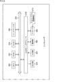
- FIG. 32 shows a configuration example of an embodiment of a computer in which a program for executing the series of processes described above is installed.
- the program can be recorded in advance in a hard disk 205 or ROM 203 as a recording medium built in the computer.
- the program is stored temporarily on a removable recording medium 211 such as a flexible disk, CD-ROM (Compact Disc Read Only Memory), MO (Magneto Optical) disc, DVD (Digital Versatile Disc), magnetic disk, semiconductor memory, or the like. It can be stored permanently (recorded).
- a removable recording medium 211 can be provided as so-called package software.
- the program can be wirelessly transferred from the download site to the computer via an artificial satellite for digital satellite broadcasting, or LAN (Local Area Network),
- the program can be transferred to a computer via a network such as the Internet.
- the computer can receive the program transferred in this way by the communication unit 208 and install it in the built-in hard disk 205.
- the computer has a CPU (Central Processing Unit) 202 built-in.
- An input / output interface 210 is connected to the CPU 202 via the bus 201, and the CPU 202 operates the input unit 207 including a keyboard, a mouse, a microphone, and the like by the user via the input / output interface 210.
- a program stored in a ROM (Read Only Memory) 203 is executed accordingly.
- the CPU 202 also receives a program stored in the hard disk 205, a program transferred from a satellite or a network, received by the communication unit 208 and installed in the hard disk 205, or a removable recording medium 211 attached to the drive 209.
- the program read and installed in the hard disk 205 is loaded into a RAM (Random Access Memory) 204 and executed.
- the CPU 202 performs processing according to the above-described flowchart or processing performed by the configuration of the above-described block diagram.
- the CPU 202 outputs the processing result from the output unit 206 configured with an LCD (Liquid Crystal Display), a speaker, or the like via the input / output interface 210, or from the communication unit 208 as necessary. Transmission, and further recording on the hard disk 205 is performed.
- processing steps for describing a program for causing a computer to perform various types of processing do not necessarily have to be processed in time series according to the order described in the flowchart, but in parallel or individually. This includes processing to be executed (for example, parallel processing or processing by an object).
- the program may be processed by one computer, or may be processed in a distributed manner by a plurality of computers. Furthermore, the program may be transferred to a remote computer and executed.
- the present technology can take a cloud computing configuration in which one function is shared by a plurality of devices via a network and is jointly processed.
- each step described in the above flowchart can be executed by one device or can be shared by a plurality of devices.
- the plurality of processes included in the one step can be executed by being shared by a plurality of apparatuses in addition to being executed by one apparatus.
- this technique can also take the following structures.
- a first LDPC encoding unit that generates an LDPC code of a predetermined information word using the first check matrix;
- a first parity interleaving unit for interleaving parity bits of the LDPC code;
- a coding apparatus comprising: a second LDPC coding unit that generates an ETRI-format LDPC code using a second check matrix for the LDPC code in which the parity bits are interleaved.
- the LDPC encoding unit is An encoding unit that integrates a product of the information word and the information matrix of the first parity check matrix or the second parity check matrix corresponding to the information word;
- the encoding device according to (2) further including an integration unit that generates the parity bits of the LDPC code by integrating the integration results by the encoding unit.
- the LDPC encoding unit executes the processing by the encoding unit twice, and after the first processing, executes the processing of the integration unit.
- the encoding device according to (3) wherein the processing of the integration unit is not performed after the processing.
- the encoding device according to any one of (2) to (4), wherein the first parity interleaving unit also performs interleaving of parity bits of the ETRI format LDPC code.
- the encoding apparatus according to any one of (1) to (4), further including a second parity interleaving unit that interleaves parity bits of the ETRI format LDPC code.
- the encoding apparatus wherein the first LDPC encoding unit and the second LDPC encoding unit are configured by different LDPC encoding units.
Landscapes
- Physics & Mathematics (AREA)
- Engineering & Computer Science (AREA)
- Theoretical Computer Science (AREA)
- Probability & Statistics with Applications (AREA)
- Mathematical Physics (AREA)
- Computational Mathematics (AREA)
- General Physics & Mathematics (AREA)
- Mathematical Analysis (AREA)
- Mathematical Optimization (AREA)
- Pure & Applied Mathematics (AREA)
- Computer Networks & Wireless Communication (AREA)
- Algebra (AREA)
- Computing Systems (AREA)
- Multimedia (AREA)
- Error Detection And Correction (AREA)
Abstract
本技術は、DVB-Like LDPC符号とETRI形式LDPC符号に対応することができるようにする符号化装置及び符号化方法に関する。 符号化装置は、第1の検査行列を用いて、所定の情報語のLDPC符号を生成する第1LDPC符号化部と、前記LDPC符号のパリティビットをインターリーブする第1パリティインターリーブ部と、前記パリティビットがインターリーブされた前記LDPC符号に対して、第2の検査行列を用いて、ETRI形式LDPC符号を生成する第2LDPC符号化部とを備える。本技術は、例えば、符号化装置等に適用できる。
Description
本技術は、符号化装置及び符号化方法に関し、特に、DVB-Like LDPC符号とETRI形式LDPC符号に対応することができるようにする符号化装置及び符号化方法に関する。
LDPC(Low Density Parity Check)符号は、高い誤り訂正能力を有し、近年では、例えば、欧州等のDVB(Digital Video Broadcasting)-S.2等のディジタル放送等の伝送方式に広く採用されている(例えば、非特許文献1を参照)。
また、DVB-T.2、DVB-C.2のディジタル放送等の伝送方式には、上記DVB-S.2に準拠したLDPC符号のパリティビットを、他のパリティビットの位置にインターリーブしたLDPC符号(以下、DVB-Like LDPC符号という。)が採用されている(例えば、非特許文献2を参照)。
DVB-S.2 : ETSI EN 302 307 V1.2.1 (2009-08)
DVB-T2: ETSI EN 302 755 V1.3.1 (2012-04)
ところで、ATSC(Advanced Television Systems Committee)3.0と呼ばれるディジタル放送の規格では、DVB-Like LDPC符号と、カナダのCommunications Research Centreと韓国のElectronics and Telecommunications Research Institute(以下、CRC/ETRIと記述する。)が提案する形式のLDPC符号(以下、ETRI形式LDPC符号という。)とが採用される予定で進められており、両方の形式に対応した符号化装置が望まれている。
本技術は、このような状況に鑑みてなされたものであり、DVB-Like LDPC符号とETRI形式LDPC符号に対応することができるようにするものである。
本技術の一側面の符号化装置は、第1の検査行列を用いて、所定の情報語のLDPC符号を生成する第1LDPC符号化部と、前記LDPC符号のパリティビットをインターリーブする第1パリティインターリーブ部と、前記パリティビットがインターリーブされた前記LDPC符号に対して、前記第1の検査行列を一部として含む第2の検査行列を用いて、ETRI形式LDPC符号を生成する第2LDPC符号化部とを備える。
本技術の一側面の符号化方法は、第1の検査行列を用いて、所定の情報語のLDPC符号を生成する第1LDPC符号化ステップと、前記LDPC符号のパリティビットをインターリーブするパリティインターリーブステップと、前記パリティビットがインターリーブされた前記LDPC符号に対して、前記第1の検査行列を一部として含む第2の検査行列を用いて、ETRI形式LDPC符号を生成する第2LDPC符号化ステップとを備え、前記第1LDPC符号化ステップと前記パリティインターリーブステップを実行し、その後、そのまま出力するか、または、前記第2LDPC符号化ステップを実行して出力するかを切り替える。
本技術の一側面においては、第1の検査行列を用いて、所定の情報語のLDPC符号が生成され、前記LDPC符号のパリティビットがインターリーブされる。また、パリティビットがインターリーブされた前記LDPC符号に対して、前記第1の検査行列を一部として含む第2の検査行列を用いて、ETRI形式LDPC符号が生成される。
符号化装置は、独立した装置であっても良いし、1つの装置を構成している内部ブロックであっても良い。
本技術の一側面によれば、DVB-Like LDPC符号とETRI形式LDPC符号に対応することができる。
なお、ここに記載された効果は必ずしも限定されるものではなく、本開示中に記載されたいずれかの効果であってもよい。
以下、本技術を実施するための形態(以下、実施の形態という)について説明する。なお、説明は以下の順序で行う。
1.LDPC符号の説明
2.DVB-Like LDPC符号の説明
3.ETRI形式LDPC符号の説明
4.第1の実施の形態(基本構成例)
5.第2の実施の形態(所定ブロックを共通化した第1構成例)
6.第3の実施の形態(所定ブロックを共通化した第2構成例)
1.LDPC符号の説明
2.DVB-Like LDPC符号の説明
3.ETRI形式LDPC符号の説明
4.第1の実施の形態(基本構成例)
5.第2の実施の形態(所定ブロックを共通化した第1構成例)
6.第3の実施の形態(所定ブロックを共通化した第2構成例)
<概要>
ATSC(Advanced Television Systems Committee)3.0と呼ばれるディジタル放送の規格では、DVB-S.2等に準拠したLDPC符号のパリティビットを他のパリティビットの位置にインターリーブしたLDPC符号(以下、DVB-Like LDPC符号という。)と、CRC/ETRIが提案する形式のLDPC符号(以下、ETRI形式LDPC符号という。)とが採用される予定で進められており、両方の形式に対応した符号化装置が望まれている。
ATSC(Advanced Television Systems Committee)3.0と呼ばれるディジタル放送の規格では、DVB-S.2等に準拠したLDPC符号のパリティビットを他のパリティビットの位置にインターリーブしたLDPC符号(以下、DVB-Like LDPC符号という。)と、CRC/ETRIが提案する形式のLDPC符号(以下、ETRI形式LDPC符号という。)とが採用される予定で進められており、両方の形式に対応した符号化装置が望まれている。
後述する図22等において、DVB-Like LDPC符号とETRI形式LDPC符号の両方の形式に対応した符号化装置を提案するが、その前に、LDPC符号、DVB-Like LDPC符号、ETRI形式LDPC符号のそれぞれについて説明する。
<1.LDPC符号の説明>
まず初めに、DVB(Digital Video Broadcasting)-S.2等で採用されているLDPC符号について説明する。
まず初めに、DVB(Digital Video Broadcasting)-S.2等で採用されているLDPC符号について説明する。
なお、LDPC符号は、線形符号であり、必ずしも2元である必要はないが、ここでは、2元であるものとして説明する。
LDPC符号は、そのLDPC符号を定義する検査行列(parity check matrix)が疎なものであることを最大の特徴とするものである。ここで、疎な行列とは、行列のコンポーネントの"1"の個数が非常に少なく構成されるものであり、疎な検査行列をHで表すものとすると、そのような検査行列Hとしては、例えば、図1に示すように、各列のハミング重み("1"の数)(weight)が"3"であり、且つ、各行のハミング重みが"6"であるもの等がある。
このように、各行及び各列のハミング重みが一定である検査行列Hによって定義されるLDPC符号は、レギュラーLDPC符号と称される。一方、各行及び各列のハミング重みが一定でない検査行列Hによって定義されるLDPC符号は、イレギュラーLDPC符号と称される。
このようなLDPC符号への符号化は、検査行列Hに基づいて生成行列Gを生成し、この生成行列Gを2元の情報語iに対して乗算することによって符号語を生成することで実現される。具体的には、LDPC符号に符号化する符号化装置は、まず、検査行列Hの転置行列HTとの間に、式GHT=0が成立する生成行列Gを算出する。ここで、生成行列Gが、k×n行列(k行n列の行列)である場合には、検査行列Hは、n-k行n列の行列である。
なお、例えば、nビットの符号語cが、kビットの情報語iに続けて、n-kビットのパリティビットpを配置したビット列に一致する組織符号である場合に、n-k行n列の検査行列Hにおいて、nビットの符号語cのうちのkビットの情報語iに対応するn-k行k列の部分を情報部というとともに、n-kビットのパリティビットpに対応するn-k行n-k列の部分をパリティ部ということとすると、パリティ部が、下三角行列または上三角行列になっていれば、情報語iのLDPC符号への符号化は、検査行列Hを用いて行うことができる。
即ち、例えば、検査行列Hが、図2に示すように、情報部と、下三角行列のパリティ部とで構成され、パリティ部の下三角の部分の要素が、すべて1であるとすると、符号語cのパリティビットpの0番目のビットは、情報語iのうちの、検査行列Hの情報部の第0行において1になっている要素に対応するビットのEXOR(排他的論理和)を演算した値となる。
また、符号語cのパリティビットpの1番目のビットは、情報語iのうちの、検査行列Hの情報部の第1行において1になっている要素に対応するビットと、パリティビットpの0番目のビットのEXORを演算した値となる。
さらに、符号語cのパリティビットpの2番目のビットは、情報語iのうちの、検査行列Hの情報部の第2行において1になっている要素に対応するビットと、パリティビットpの0番目および1番目のビットのEXORを演算した値となる。
以下、同様にして、符号語cのパリティビットpのm番目のビットは、情報語iのうちの、検査行列Hの情報部の第m行において1になっている要素に対応するビットと、パリティビットpの0乃至m-1番目のビットのEXORを演算した値となる。
以上のようにして、n-kビットのパリティビットpを求め、kビットの情報語iに続けて配置することにより、nビットの符号語cを得ることができる。
即ち、パリティ部が下三角行列の検査行列Hを図3に示すように一般化すると、情報語iのLDPC符号への符号化は、検査行列Hを用いて以下のように行われる。
図3では、検査行列Hの0行目(最上行)の成分は、0列目(左端列)から順に、情報部がh0,0,h0,1,・・・・h0,k-1となり、パリティ部が1,0,・・・0となっている。また、1行目の成分は、0列目から順に、情報部がh1,0,h1,1,・・・・,h1,k-1となり、パリティ部がh1,k,1,0,・・・0となっている。以下、同様にして、n-k-1行目(最下行)の成分は、0列目から順に、情報部がhn-k-1,0,hn-k-1,1,・・・・,hn-k-1,k-1となり、パリティ部がhn-k-1,k,・・・,hn-k-1,n-2,1となっている。
ここで、kビットの情報語iをi0,i1,・・・,ik-1と表し、n-kビットのパリティビットpをp0,p1,・・・,pn-k-1と表すとする。即ち、符号語cは、i0,i1,・・・,ik-1,p0,p1,・・・,pn-k-1で表される。符号語cと検査行列Hの各行との積の排他的論理和は0であるので、符号語cと検査行列Hの0行目との積の演算は、以下の式(1)で表される。

従って、パリティビットp0は、以下の式(2)で表される。

また、符号語cと検査行列Hの1行目との積の演算は、以下の式(3)で表される。

従って、パリティビットp1は、以下の式(4)で表される。

同様に、符号語cと検査行列Hのn-k-1行目との積の演算は、以下の式(5)で表される。

従って、パリティビットpn-k-1は、以下の式(6)で表される。

以上のようにして、n-kビットのパリティビットp0,p1,・・・,pn-k-1を求め、kビットの情報語iであるi0,i1,・・・,ik-1に続けて配置することにより、nビットの符号語cを得ることができる。
なお、情報語iとLDPC符号の符号語cにおいては、1ビットを{0,・・・,q}(q≧1)で表すことが可能であり、必ずしも2元である必要はないが、以下では、2元であるものとして説明する。
図4は、LDPC符号化に用いる検査行列Hの例を示している。
図4の検査行列Hは、n=108,k=72の符号語c(符号化率2/3、符号長108)を得るための検査行列Hであり、36(行)×108(列)の行列である。なお、図4の検査行列Hでは(後述する図5乃至7,22、および25の行列においても同様)、0を、"."で表現している。また、図4の検査行列Hは、6×6の行列の単位に間隔を空けて表したものである。
即ち、検査行列Hは、36(=n-k)行72(=k)列の情報部と、36(=n-k)行36(=n-k)列のパリティ部とから構成される。LDPC符号への符号化においては、情報部は、LDPC符号の符号語cの情報語iと乗算され、パリティ部は、符号語cのパリティビットpと乗算される。
図4の検査行列Hでは、LDPC符号の情報語iに対応する情報部の各行は、7個の“1”と、101個の“0”から構成される。パリティ部は、下三角状の構造を有する行列(下三角行列)となっている。即ち、図4の検査行列Hのパリティ部は、行列の対角線の右上が全て“0”とされた行列となっており、下三角状の構造を有している。
図5と図6は、図4の検査行列Hを行置換または列置換した後の検査行列H´を示している。
図5の検査行列H´では、情報部を、P×P(図5の例の場合、P=6)の単位行列、その単位行列の1のうち1個以上が0になった行列(以下、適宜、準単位行列という)、単位行列または準単位行列をサイクリックシフト(cyclic shift)した行列(以下、適宜、シフト行列という)、単位行列、準単位行列、またはシフト行列のうちの2以上(複数)の和(以下、適宜、和行列という)、P×Pの0行列の組み合わせで表すことができる。なお、以下では、P×Pの単位行列、準単位行列、シフト行列、和行列、0行列を、以下、適宜、構成行列という。
図6の検査行列Hは、図5に示した検査行列Hを、6×6の構成行列の単位に間隔を空けて表したものである。検査行列Hを構成する横方向の構成行列の数をn0個とし、検査行列Hの情報部を構成する横方向の構成行列の数をk0個とすると、n0(=n/P=108/6)は18となり、k0(=k/P=72/6)は12となる。
即ち、図5や図6の検査行列Hでは、縦方向に6(=n0-k0=18-12)個の構成行列が、横方向にn0(=18)個の構成行列が並んでいる。
また、図4の検査行列Hの最上行(先頭行)を0行目とすると、検査行列Hの(n0-k0)×v+w(0≦v≦P-1,0≦w≦n0-k0-1)行目の行は、図5や図6の検査行列H´では、P×w+v行目の行となっている。
図5や図6の検査行列H´を用いてLDPC符号化を行うことにより、LDPC符号化に必要な演算である検査行列H´の情報部の各行と情報語iとの積算を、情報語iを6個単位でサイクリックシフトすることで行うことができる。即ち、構成行列であるP×Pの単位行列、準単位行列、またはシフト行列、もしくは構成行列の和行列を複数の行列に分解したときのP×Pの単位行列、準単位行列、またはシフト行列の各行の“1”の数は1個であるので、その構成行列に対応する6個の情報語iをサイクリックシフトすることで、検査行列H´の情報部の各行と情報語iとの積を算出することができる。
図7のA乃至図7のBは、図4の検査行列Hと図5や図6の検査行列H´のパリティ部を示している。
図7のAに示すように、図4の検査行列Hのパリティ部は、行列の対角線の右上が全て“0”とされた行列となっており、下三角状の構造を有している。また、パリティ部は、下三角行列の対角成分とその成分の直下の成分が1であり、それ以外の成分が0となっている。これにより、LDPC符号化におけるパリティビットpを求める演算を容易に行うことができる。
図7のBに示すように、図5や図6の検査行列H´のパリティ部では、図7のAのパリティ部の(n0-k0)×v+w行目の行が、P×w+v行目の行となる。
図8は、上述したLDPC符号を生成する符号化装置1の構成例を示すブロック図である。
図8の符号化装置1は、図4の検査行列Hを用いて、情報語iをLDPC符号化し、その結果得られる符号語cを出力する。
符号化装置1は、ビット幅調整回路11、サイクリックシフト回路12、加算器13、RAM14、インターリーバ15、アキュムレータ16、セレクタ17、および制御部18から構成される。
ビット幅調整回路11には、情報語D11(情報語i)が2ビット単位で供給され、ビット幅調整回路11は、2ビット単位で供給された情報語D11を3つ合わせて、6ビット単位で情報語D12としてサイクリックシフト回路12に供給する。
サイクリックシフト回路12には、制御部18から、情報語D12に対応する検査行列H´の情報部の1が、検査行列H´において元となる単位行列などを幾つサイクリックシフトしたものであるかの情報を表す制御信号D21が供給される。サイクリックシフト回路12は、制御信号D21に基づいて、ビット幅調整回路11から順次供給される12(=k0)個の6ビットの情報語D12をサイクリックシフトすることにより、検査行列H´を構成する構成行列のうち0行列ではない構成行列の各行の値hと情報語D12との積(h×i)を求め、加算器13に順次供給(出力)する。
なお、構成行列が和行列である場合、即ち構成行列のハミング重みが2以上である場合、サイクリックシフト回路12は、和行列を単位行列、準単位行列、またはシフト行列のうちの複数の行列の和に分解したときの、その行列単位で、行列と情報語D12との積を求め、それらを対応する行ごとにEXOR演算(加算)した値を、情報語D13として加算器13に供給する。また、サイクリックシフト回路12は、6ビット単位で情報語D12のサイクリックシフトを行うようにしたが、6(=P)の約数個のビット単位でサイクリックシフトを行うようにしてもよい。
加算器13は、6つの加算器(図示せず)から構成され、各加算器は、サイクリックシフト回路12からの6ビットの積D13とRAM14からの6ビットの和D14とのEXORをビット毎に求め、その結果得られる6ビットの値を和D15(第1の積算値)としてRAM14に供給することにより、積D13を6行単位で行ごとに積算する。
RAM14には、制御部18から、データの読み出しまたは書き込みを行うアドレスを指定する制御信号D22が供給される。RAM14は、その制御信号D22に基づいて、加算器13からの和D15を6ビット単位で記憶したり、既に記憶している和D15を6ビットまたは2ビット単位で読み出す。
このように、RAM14は、6ビットまたは2ビットの和D15を同時に記憶したり、読み出すことができるので、LDPC符号化における処理を6ビットまたは2ビット単位で行うことができる。その結果、符号化装置1では、適度な回路規模と動作周波数でLDPC符号化を行うことができる。
RAM14は、6ビット単位で読み出した和D15を、和D14として加算器13に供給したり、2ビット単位で読み出した和D15を、和D16としてインターリーバ15に供給する。なお、RAM14のビット数は6(=P)であり、ワード数は6(=n0-k0)である。
インターリーバ15は、RAM14から供給される和D16の順序を制御する。具体的には、インターリーバ15は、和D16を検査行列Hに対応する順序に並べ替え、並べ替え後の和D17をアキュムレータ16に供給する。
アキュムレータ16には、制御部18から、アキュムレータ16のセレクタ62(後述する図14)における選択を表す選択信号D23が供給され、アキュムレータ16は、その選択信号D23とインターリーバ15から順次供給される和D17とに基づいて、所定の演算(例えば、式(2),(4),(6))を行い、その結果得られるパリティビットpを2ビット単位でパリティビットD18としてセレクタ17に順次供給(出力)する。即ち、アキュムレータ16は、和D17を積算し、その結果得られるパリティビットpを2ビット単位でパリティビットD18(第2の積算値)としてセレクタ17に供給する。
セレクタ17には、所定の時間遅延された情報語iが2ビット単位で情報語D19として供給される。セレクタ17は、制御部18からの、パリティビットD18と情報語D19のいずれか一方の選択を表す選択信号D24に基づいて、アキュムレータ16からのパリティビットD18と情報語D19のうちのいずれか一方を選択し、2ビット単位で符号語D20(符号語c)として出力する。具体的には、セレクタ17は、kビットの情報語D19を2ビット単位で出力し、その後n-kビットのパリティビットD18を2ビット単位で出力することにより、符号語D20を出力する。
制御部18は、制御信号D21をサイクリックシフト回路12に、制御信号D22をRAM14に、選択信号D23をアキュムレータ16に、選択信号D24をセレクタ17に供給する。
図9を参照して、図8のサイクリックシフト回路12が行うサイクリックシフトの量について説明する。
なお、以下では、ビット幅調整回路11から供給される情報語iの(6×s)乃至(6×(s+1)-1)ビット目(s=0,1,2,・・・,k0-1)の情報語D12をs番ベクトルという。
図9において、最上行の数字はベクトルの番号を表し、左端の数字は、検査行列H´の構成行列の上からの番号を表している。なお、構成行列の上からの番号は、0から順に付与するものとする。また、図9において、「-」はサイクリックシフト回路12が情報語D13を出力しないことを表している。
例えば、第m行第l列を、(m,l)と表すこととすると、図6に示すように、検査行列H´の(0,0)から(5,5)の構成行列は単位行列、(6,0)から(11,5)の構成行列は和行列(6×6の単位行列を右方向に2つだけサイクリックシフトした第1のシフト行列と、右方向に4つだけサイクリックシフトした第2のシフト行列の和である和行列)、(12,0)から(17,5)の構成行列は0行列、(18,0)から(23,5)の構成行列はシフト行列(6×6の単位行列を右方向に3つだけサイクリックシフトしたシフト行列)、(24,0)から(29,5)の構成行列は0行列、(30,0)から(35,5)の構成行列はシフト行列(6×6の単位行列を右方向に5つだけサイクリックシフトしたシフト行列)となっている。
そこで、サイクリックシフト回路12は、検査行列H´の左から0乃至5列目を構成する構成行列に応じて、まず最初に、サイクリックシフトを行わず、0番ベクトルと検査行列H´の(0,0)から(5,5)の構成行列との積として、0番ベクトルをそのまま積D13として出力する。即ち、図9に示すように、0番ベクトルと検査行列H´の上から0番目の構成行列との積を求める場合、サイクリックシフト回路12のサイクリックシフト量は0回となる。
次に、サイクリックシフト回路12は、0番ベクトルを右方向に2つだけサイクリックシフトするとともに、0番ベクトルを右方向に4つだけサイクリックシフトし、その結果得られる2つのサイクリックシフト後の6ビットの情報語D12をEXOR演算することにより、0番ベクトルと(6,0)から(11,5)の構成行列との積を求める。即ち、(6,0)から(11,5)の構成行列を第1のシフト行列と第2のシフト行列の和に分解したときの、第1のシフト行列と第2のシフト行列それぞれに対して得られる情報語D12が、加算器13を介して、RAM14の同一のアドレスに格納されるように、サイクリックシフト回路12は、第1と第2のシフト行列それぞれに対して得られる情報語D12をEXOR演算する。そして、サイクリックシフト回路12は、その求めた積を、積D13として出力する。
即ち、図9に示すように、0番ベクトルと検査行列H´の上から1番目の構成行列との積を求める場合、サイクリックシフト回路12のサイクリックシフト量は右方向に2回と4回である。
ここで、検査行列H´の上から2番目の(12,0)から(17,5)の構成行列は0行列であるので、その構成行列については、サイクリックシフト回路12は何も処理を行わず、何も出力しない(図9の「-」)。
以下、同様にして、サイクリックシフト回路12は、0番ベクトルを右方向に3回サイクリックシフトすることにより、0番ベクトルと検査行列H´の3番目の(18,0)から(23,5)の構成行列との積を求め、0番ベクトルを左方向に5回サイクリックシフトすることにより、0番ベクトルと(30,0)から(35,5)の構成行列との積を求める。そして、サイクリックシフト回路12は、サイクリックシフト後の情報語D12を積D13として出力する。
以上のようにして、サイクリックシフト回路12は、1回目にビット幅調整回路11から供給される0番ベクトルと、検査行列H´の左から0乃至5(=P-1)列目との積をそれぞれ求める。
以降も同様に、サイクリックシフト回路12は、2乃至12回目にビット幅調整回路11から供給される1乃至11番ベクトルと、検査行列H´の左から6乃至71列目との積をそれぞれ求める。
次に、図10と図11を参照して、図8のRAM14に記憶される和D15について説明する。
なお、以下の説明に用いるRAM14のワード方向とは、図10に示すように、図中横方向であり、左端から順に0番アドレス、1番アドレス、2番アドレス、・・・という。また、RAM14のビット方向とは、図中縦方向であり、上から順に0ビット目、1ビット目、2ビット目、・・・という。
また、以下では、検査行列H´の上からv番目の構成行列の上からw行目(=P×v+w=6×v+w)と0乃至11番ベクトルのそれぞれとの積の和D15を、ow,vとも表す。即ち、ow,vは、以下の式(7)で表される。
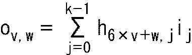
図11に示すように、RAM14のビット数はP(=6)であり、ワード数は、n0-k0(=6)である。まず最初に、RAM14には、サイクリックシフト回路12から加算器13を介して、0番ベクトルと検査行列H´の上から0番目の構成行列との積が6ビットの和D15として供給され、RAM14は、その和D15の各ビットを0番アドレスの0ビット目から順に記憶する。
次に、RAM14には、サイクリックシフト回路12から加算器13を介して、1番ベクトルと検査行列H´の上から1番目の構成行列との積が6ビットの和D15として供給され、RAM14は、その和D15の各ビットを1番アドレスの0ビット目から順に記憶する。以降、同様にして、RAM14の2乃至5番アドレスにも、和D15が記憶される。
また、RAM14は、0番アドレスの0乃至5ビット目に記憶されている0番ベクトルと検査行列H´の上から0番目の構成行列との積を読み出し、6ビットの和D14として加算器13に供給する。以降、同様にして、RAM14の1乃至5番アドレスに記憶されている6ビットの和D15をそれぞれ読み出し、和D14として加算器13に供給する。
加算器13は、RAM14から6ビットの和D14として供給される0番ベクトルと検査行列H´の上から0番目の構成行列との積と、サイクリックシフト回路12から供給される1番ベクトルと検査行列H´の上から0番目の構成行列との積とをEXOR演算し、その結果得られる和D15をRAM14に供給する。RAM14は、その和D15の各ビットを0番アドレスの0ビット目から順に記憶する。即ち、RAM14は、0番アドレスを更新する。以降、同様にして、RAM14は、1乃至5番アドレスも更新する。
そして、同様の処理が繰り返され、RAM14の0番アドレスの0ビット目には、検査行列H´の上から0番目の構成行列の上から0行目と0乃至11番ベクトルのそれぞれとの積の和D15であるo0,0が記憶される。また、RAM14の0番アドレスの1乃至5ビット目には、o1,0,乃至o5,0がそれぞれ記憶される。
同様に、RAM14の1番アドレスの0乃至5ビット目には、それぞれo0,1,乃至o5,1が、2番アドレスの0乃至5ビット目には、それぞれo0,2,乃至o5,2が、RAM14の3番アドレスの0乃至5ビット目には、それぞれo0,3,乃至o5,3が、RAM14の4番アドレスの0乃至5ビット目には、それぞれo0,4,乃至o5,4が、5番アドレス0乃至5ビット目には、それぞれo0,5,乃至o5,5が記憶される。
以上のように、RAM14のアドレスは、検査行列Hの情報部の6行に対応し、RAM14は、図中左上から右下方向に向かって、和D15に対応する検査行列H´の上からの行数(6×v+w)が大きくなるように、和D15(o0,0,乃至o5,5)を記憶する。また、RAM14は、o0,0,乃至o5,5を、検査行列H´の構成行列の1を列方向(横方向)に詰めるように記憶(格納)する。
ここで、ビット方向(縦方向)での順番がP×x+y(x=0,1,・・・,5,y=0,1,・・・,5)番目の和D15は、ワード方向(横方向)での順番が(n0-k0)×y+x番目となる。なお、ビット方向の順番は、各番号アドレスの5ビット目の次が、右隣のアドレス(次の番号のアドレス)の0ビット目となるものとする。また、ワード方向の順番は、各ビットの5番アドレスの次が、直下のビット(次のビット)の0番アドレスとなるものとする。例えば、ビット方向での順番が6番目の和D15はo0,1となり、ワード方向での順番が6番目の和D15はo1,0となる。
上述したように、検査行列Hの(n0-k0)×v+w行目の行は、図5の検査行列H´では、P×w+v行目の行となる。即ち、検査行列H´のP×w+v行目の行は、検査行列Hの(n0-k0)×v+w行目の行である。従って、RAM14のビット方向に検査行列H´の0行目から順に和D15として記憶される、検査行列H´の情報部の各行と0乃至11番ベクトルのそれぞれとの積の和であるow,vは、ワード方向の順番に見ると、検査行列Hの0行目から順に対応する積の和であるow,vとなる。
しかしながら、RAM14は、一般的に2つ以上のアドレスに同時にアクセスすることができないため、ワード方向に和D15を読み出すことはできない。従って、符号化装置1では、インターリーバ15により、RAM14がビット方向に読み出した和D15の順序を入れ替えている。インターリーバ15の詳細については、後述する図12と図13を参照して説明する。
図12は、図8のインターリーバ15の詳細構成例を示す図である。
図12のインターリーバ15は、5つのレジスタ41-1乃至41-5および5つのレジスタ42-1乃至42-5、並びにセレクタ43から供給される。
インターリーバ15には、RAM14から2ビットの和D16が供給され、そのうちの1ビットが和D41としてレジスタ41-1乃至41-5に1ビット単位で順に記憶される。また、他の1ビットが和D42としてレジスタ42-1乃至42-5に1ビット単位で順に記憶される。レジスタ41-1乃至41-5とレジスタ42-1乃至42-5は、記憶している1ビットの和D41またはD42をそれぞれセレクタ43に供給する。
セレクタ43は、レジスタ41-1乃至41-5とレジスタ42-1乃至42-5のそれぞれから供給される5つの和D41またはD42のうち、いずれか2つの和D41またはD42を選択し、和D43とD44として出力する。1ビットの和D43とD44は合わせられ、2ビットの和D17としてアキュムレータ16に供給される。
以上のように、インターリーバ15では、レジスタ41-1乃至41-5およびレジスタ42-1乃至42-5が、入力された和D16(和D41またはD42)を記憶し、セレクタ43が、そのレジスタ41-1乃至41-5およびレジスタ42-1乃至42-5に記憶されている和D16を選択して、和D17(和D43またはD44)として出力することにより、入力される和D16と出力される和D17の順序を入れ替える。
次に、図13を参照して、図12のインターリーバ15におけるデータの入出力を説明するタイミングチャートである。図13において、横軸は時間を表している。
図13に示すように、まず最初に、RAM14は、0番アドレスに記憶されているo0,0,とo1,0の2ビットを、和D16として読み出してインターリーバ15に出力する。即ち、インターリーバ15には、o0,0,とo1,0が和D16として入力される。
次に、RAM14は、1番アドレスに記憶されているo0,1,とo1,1の2ビットを、和D16としてインターリーバ15に出力する。以降、同様にして、RAM14は、2乃至5番アドレスに記憶されているo0,2,とo1,2、o0,3,とo1,3、o0,4,とo1,4、またはo0,5,とo1,5を、和D16としてそれぞれインターリーバ15に出力する。
図12のインターリーバ15のレジスタ41-1乃至41-5には、例えば、インターリーバ15に入力される和D16のうちの1ビットであるo0,0乃至o0,5が順に供給され、記憶される。また、他の1ビットであるo1,0乃至o5,0がレジスタ42-1乃至42-5に順に供給され、記憶される。そして、レジスタ41-1乃至41-5と42-1乃至42-5は、o0,0乃至o0,5とo1,0乃至o5,0をそれぞれセレクタ43に供給する。
図13に示すように、セレクタ43は、まず最初にo0,0とo0,1を選択し、和D43とD44としてそれぞれ出力する。即ち、o0,0とo0,1が和D17としてアキュムレータ16に入力される。次に、セレクタ43は、o0,2とo0,3を選択し、それぞれ和D43とD44として出力する。その後、セレクタ43は、o0,4とo0,5、o1,0とo1,1、o1,2とo1,3、o1,4とo1,5の順に選択して出力する。
即ち、インターリーバ15に入力される和D16のうちの1ビットであるRAM14の0ビット目に記憶されるo0,0乃至o0,5を系列#1といい、他の1ビットであるRAM14の1ビット目に記憶されるo1,0乃至o5,0を系列#2というと、セレクタ43は、系列#1をo0,0から順に2ビットずつ選択し、その後系列#2をo1,0から順に2ビットずつ選択する。即ち、セレクタ43は、入力される和D16を、その和D16が記憶されているRAM14のワード方向の順番に2ビットずつ選択する。
以上のように、インターリーバ15は、RAM14のビット方向の順番に読み出され、入力される2ビットの和D16を、その和D16が記憶されているRAM14のワード方向の順番に2ビットずつ選択して出力するので、検査行列Hの情報部の各行と0乃至11番ベクトルのそれぞれとの積の和であるow,vを、検査行列Hの情報部の0行目から順に、2ビット単位で和D17として出力することができる。
図14は、図8のアキュムレータ16の詳細構成例を示している。
図14のアキュムレータ16は、加算器61と63、並びにセレクタ62から構成される。
加算器61には、インターリーバ15から2ビットの和D17のうちの1ビットである和D61が供給されるとともに、加算器63から前回の加算の結果得られたパリティビットD65が供給される。加算器61は、和D61とパリティビットD65を加算し、その結果得られる値を和D63として、セレクタ62に供給する。
セレクタ62には、和D61が供給されるとともに、制御部18から選択信号D23が供給され、セレクタ62は、選択信号D23に基づいて、和D61またはD63をパリティビットD64として、セレクタ17と加算器63に出力する。
加算器63には、インターリーバ15から2ビットの和D17のうちの和D61以外の1ビットである和D62が供給される。加算器63は、セレクタ62から供給される前回の加算の結果得られたパリティビットD64と和D62とを加算し、その結果得られる値をパリティビットD65として、セレクタ17と加算器61に出力する。なお、セレクタ62と加算器63から出力されるパリティビットD64とD65は合わせられ、2ビットのパリティビットD18(パリティビットp)としてセレクタ17に供給される。
図15と図16を参照して、図14のアキュムレータ16で行われるパリティビットpの演算について説明する。
図15と図16に示すように、上述した式(2)と式(7)により、パリティビットp0=o0,0となる。また、上述した式(3)と式(7)により、図15に示すように、o0,1+h1,kp0+p1=0となり、検査行列Hではh1,kは1であるので、o0,1+p0+p1=0(o0,1=p0+p1)となる。即ち、図16に示すように、パリティビットp1=o0,0+p0である。
具体的には、図14のアキュムレータ16に、インターリーバ15からo0,0とo0,1の2ビットの和D17が供給され、加算器61とセレクタ62にo0,0が和D61として供給され、加算器63にo0,1が和D62として供給される。このとき、まだ加算器63による加算が行われていないので、加算器61にはパリティビットD65が供給されておらず、加算器63は、和D61をそのまま和D63としてセレクタ62に供給する。
セレクタ62は、選択信号D23に基づいてインターリーバ15からの和D61(いまの場合、o0,0)を選択し、パリティビットD64(いまの場合、p0)としてセレクタ17と加算器63に出力する。加算器63は、インターリーバ15からの和D62(いまの場合、o0,1)と、セレクタ62からのパリティビットD64とを加算し、その結果得られる値(いまの場合、o0,1+p0)をパリティビットD65(いまの場合、p1)として、セレクタ17と加算器61に出力する。その結果、パリティビットD64とD65が合わせられて、2ビットのパリティビットD18としてセレクタ17と加算器61に出力される。
以降、同様にして、アキュムレータ16は、図15や図16に示す式により、パリティビットp2乃至pn-k-1を2ビットずつ演算し、パリティビットD18として出力する。
次に、図17のフローチャートを参照して、図8の符号化装置1による符号化処理を説明する。この符号化処理は、例えば、情報語D11(情報語i)が2ビット単位で入力されたとき、開始される。
ステップS1において、ビット幅調整回路11は、サイクリックシフト回路12に出力する情報語D12のベクトルの番号sを0に設定し、ステップS2に進む。
ステップS2において、ビット幅調整回路11は、2ビット単位で入力される情報語D11を合わせて6ビットにし、s番ベクトル(情報語D12)としてサイクリックシフト回路12に供給する。
ステップS2の処理後は、ステップS3に進み、サイクリックシフト回路12は、制御部18からの制御信号D21に基づいて、s番ベクトルをサイクリックシフトすることにより、検査行列H´の情報部を構成する構成行列のうち、0行列ではない構成行列の各行の値hとs番ベクトルとの積(h×i)を求め、6ビットの積D13として、加算器13に供給する。
ステップS3の処理後は、ステップS4に進み、加算器13は、サイクリックシフト回路12からの6ビットの積D13と、後述するステップS5でRAM14から供給される6ビットの和D14との排他的論理和をビット毎に求め、その結果得られる6ビットの値を和D15としてRAM14に供給する。なお、最初のステップS3では、RAM14から和D14が供給されないので、加算器13は、積D13をそのまま和D15としてRAM14に供給する。
ステップS4の処理後は、ステップS5に進み、RAM14は、制御部18からの制御信号D22に基づいて、加算器13からの和D15を6ビット単位で記憶する。また、RAM14は、既に記憶している和D15を6ビットまたは2ビット単位で読み出す。RAM14は、6ビット単位で読み出した和D15を、和D14として加算器13に供給したり、2ビット単位で読み出した和D15を、和D16としてインターリーバ15に供給する。
ステップS5の処理後は、ステップS6に進み、ビット幅調整回路11は、ベクトルの番号sが11より小さいかどうかを判定し、11より小さいと判定した場合、ステップS7に進む。
ステップS7において、ビット幅調整回路11は、ベクトルの番号sを1だけインクリメントし、ステップS2に戻り、上述した処理を繰り返す。
一方、ステップS6において、ベクトルの番号sが11より小さくはない(11以上である)と判定された場合、ステップS8に進み、インターリーバ15は、ステップS5でRAM14から供給される和D16を、検査行列Hに対応する順序に並べ替え、並べ替え後の和D17をアキュムレータ16に供給する。
ステップS8の処理後は、ステップS9に進み、アキュムレータ16は、インターリーバ15からの和D17を用いて、所定の演算を行い、その結果得られるパリティビットpを、2ビット単位でパリティビットD18としてセレクタ17に供給し、ステップS10に進む。
ステップS10において、セレクタ17は、2ビット単位で遅延されて入力される情報語D19を符号語D20としてすべて出力した後、ステップS9でアキュムレータ16から供給されるパリティビットD18を2ビット単位で符号語D20として出力することにより、符号語cを出力し、処理を終了する。
以上のように、図8の符号化装置1では、加算器13が、6ビットの情報語D12と、その情報語D12に対応する検査行列Hの情報部との積を、6ビット単位で行ごとに積算し、その結果得られる和D15をRAM14に記憶させ、アキュムレータ16が、RAM14から読み出された2ビットの和D16(D15)に対応する和D17を積算し、その結果得られる2ビットのパリティビットD18をLDPC符号の符号語cのパリティビットpとして出力するので、線形符号の符号化の動作速度を変えることなく、符号化装置の回路規模を削減することができる。
上述した説明では、検査行列Hの情報部の列数kを102、構成行列の行数(または列数)Pを6としたが、情報部の列数kと構成行列の行数Pはこれに限定されない。例えば、符号化装置1は、情報語iの情報長が102より大きく、情報部の列数kが大きい検査行列Hにも適用可能であるし、6×6より大きい正方行列を構成行列として分割可能な検査行列Hにも適用可能である。
また、上述した説明では、RAM104のビット数を2、ワード数を6、個数を3としたが、ビット数、ワード数、および個数はこれに限定されず、自由度があるものとする。さらに、RAM104から同時に読み出し可能な和D104のビット数、または書き込み可能な和D104のビット数は、どのような値であってもよい。
上述した説明では、LDPC符号が2元であるものとして説明したが、2元ではなく、1ビットを{0,・・・,q}(q>1)で表す場合、アキュムレータ16によるパリティビットpの演算には、乗算と除算も必要となる。
また、上述したサイクリックシフト回路12と102として、バレルシフタを用いると回路規模を小さくすることができる。
<2.DVB-Like LDPC符号の説明>
次に、DVB-Like LDPC符号について説明する。
次に、DVB-Like LDPC符号について説明する。
<LDPC符号の検査行列>
図18は、図8の符号化装置1でLDPC符号化に用いられる検査行列Hを再び示す図である。
図18は、図8の符号化装置1でLDPC符号化に用いられる検査行列Hを再び示す図である。
ある符号長NのLDPC符号についての情報長Kとパリティ長Mは、符号化率によって決まる。また、検査行列Hは、行×列がM×Nの行列(M行N列の行列)となる。検査行列Hの情報ビットに対応する情報行列(図2の情報部)をA行列、パリティビットに対応するパリティ行列(図2のパリティ部)をB行列とすると、情報行列であるA行列は、M×Kの行列となり、パリティ行列であるB行列は、M×Mの行列となる。
DVB-T.2等の規格では、64800ビットと16200ビットの符号長NのLDPC符号が規定されている。
<パリティインターリーブ>
DVB-Like LDPC符号は、図8の符号化装置1で生成されたLDPC符号のパリティビットを、他のパリティビットの位置にインターリーブ(パリティインターリーブ)したLDPC符号である。
DVB-Like LDPC符号は、図8の符号化装置1で生成されたLDPC符号のパリティビットを、他のパリティビットの位置にインターリーブ(パリティインターリーブ)したLDPC符号である。
DVB-Like LDPC符号のパリティインターリーブについて説明する。
図8の符号化装置1が出力するLDPC符号は、例えば、DVB-T.2等の規格に規定されているLDPC符号と同様に、IRA(Irregular Repeat Accumulate)符号である。IRA符号については、例えば、"Irregular Repeat-Accumulate Codes," H. Jin, A. Khandekar, and R. J. McEliece, in Proceedings of 2nd International Symposium on Turbo codes and Related Topics, pp. 1-8, Sept. 2000に記載されている。
また、図8の符号化装置1のLDPC符号化で用いられる検査行列Hのパリティ行列(B行列)は、図19に示すように階段構造になっている。
すなわち、検査行列HのB行列(パリティ行列)は1の要素が、いわば階段状に並ぶ階段構造の行列(lower bidiagonal matrix)になっている。パリティ行列の行重みは、1行目については1で、残りの全ての行については2になっている。また、列重みは、最後の1列については1で、残りの全ての列で2になっている。
このように、パリティ行列(B行列)が階段構造になっている検査行列HのLDPC符号は、その検査行列Hを用いて、容易に生成することができる。
図20は、パリティインターリーブ後のLDPC符号に対応する検査行列Hのパリティ行列を示す図である。
ここで、図8の符号化装置1が出力するLDPC符号に対応する検査行列Hの情報行列(A行例)は、DVB-T.2等の規格に規定されているLDPC符号に対応する検査行列Hの情報行列と同様に、巡回構造になっている。
巡回構造とは、ある列が、他の列をサイクリックシフトしたものと一致している構造をいい、例えば、P列ごとに、そのP列の各行の1の位置が、そのP列の最初の列を、パリティ長Mを除算して得られる値qに比例する値等の所定の値だけ、列方向にサイクリックシフトした位置になっている構造も含まれる。以下、適宜、巡回構造におけるP列を、ユニットサイズという。
DVB-T.2等の規格に規定されているLDPC符号としては、上述したように、符号長Nが64800ビットと16200ビットとの、2種類のLDPC符号があり、その2種類のLDPC符号のいずれについても、ユニットサイズPが、パリティ長Mの約数のうちの、1とMを除く約数の1つである360に規定されている。
また、パリティ長Mは、符号化率によって異なる値qを用いて、式M=q×P=q×360で表される素数以外の値になっている。したがって、値qも、ユニットサイズPと同様に、パリティ長Mの約数のうちの、1とMを除く約数の他の1つであり、パリティ長Mを、ユニットサイズPで除算することにより得られる(パリティ長Mの約数であるP及びqの積は、パリティ長Mとなる)。
LDPC符号のパリティインターリーブを行うパリティインターリーバ(後述する図22のパリティインターリーバ55など)は、上述したように、情報長をKとし、また、0以上P未満の整数をxとするとともに、0以上q未満の整数をyとすると、パリティインターリーブとして、NビットのLDPC符号の符号ビットのうちの、K+qx+y+1番目の符号ビットを、K+Py+x+1番目の符号ビットの位置にインターリーブする。
K+qx+y+1番目の符号ビット、及び、K+Py+x+1番目の符号ビットは、いずれも、K+1番目以降の符号ビットであるから、パリティビットであり、したがって、パリティインターリーブによれば、LDPC符号のパリティビットの位置が移動される。
このようなパリティインターリーブによれば、バースト誤りに対する耐性を改善することができる。
なお、K+qx+y+1番目の符号ビットを、K+Py+x+1番目の符号ビットの位置にインターリーブするパリティインターリーブ後のLDPC符号は、元の検査行列Hの、K+qx+y+1番目の列を、K+Py+x+1番目の列に置換する列置換を行って得られる検査行列(以下、変換検査行列ともいう)のLDPC符号に一致する。
また、変換検査行列のパリティ行列には、図20に示すように、P列(図20では、360列)を単位とする擬似巡回構造が現れる。
ここで、擬似巡回構造とは、一部を除く部分が巡回構造になっている構造を意味する。
DVB-T.2等の規格に規定されているLDPC符号の検査行列に対して、パリティインターリーブに相当する列置換を施して得られる変換検査行列は、変換検査行列の右上隅部分の360行×360列の部分(シフト行列)に、1の要素が1つだけ足らず(0の要素になっており)、その点で、(完全な)巡回構造ではなく、いわば、擬似巡回構造になっている。
図8の符号化装置1が出力するLDPC符号の検査行列に対する変換検査行列は、例えば、DVB-T.2等の規格に規定されているLDPC符号の検査行列に対する変換検査行列と同様に、擬似巡回構造になっている。
なお、図20の変換検査行列は、元の検査行列Hに対して、パリティインターリーブに相当する列置換の他、変換検査行列が、後述する構成行列で構成されるようにするための行の置換(行置換)も施された行列になっている。
<3.ETRI形式LDPC符号の説明>
次に、ETRI形式LDPC符号について説明する。
次に、ETRI形式LDPC符号について説明する。
図21は、ETRI形式の検査行列Hの構造を示す図である。
ETRI形式の検査行列Hは、A行列、B行列、C行列、D行列、及び、Z行列で構成される。
A行列は、所定値gと、LDPC符号の情報長K=符号長N×符号化率rとで表されるg行K列の、検査行列の左上の行列である。A行列は、図18に示したLDPC符号の検査行列Hの情報行列と同じである。
B行列は、g行g列の、A行列の右に隣接する階段構造の行列である。B行列は、図18に示したLDPC符号の検査行列Hのパリティ行列と同じである。
C行列は、N-K-g行K+g列の、A行列及びB行列の下に隣接する行列である。
D行列は、N-K-g行N-K-g列の、C行列の右に隣接する単位行列である。
Z行列は、g行N-K-g列の、B行列の右に隣接するゼロ行列(0行列)である。
A行列及びC行列は、DVB-Like LDPC符号の検査行列の情報行列と同様に、360列(ユニットサイズP)ごとの巡回構造になっている。
ETRI形式LDPC符号は、このようなETRI形式の検査行列Hを用いてLDPC符号化したLDPC符号のB行列とD行列に対応するパリティビットをインターリーブ(パリティインターリーブ)して得られるLDPC符号である。
ETRI形式の検査行列Hは、上述したように、DVB-Like LDPC符号のLDPC符号化に用いられる検査行列Hと、A行列とB行列が共通しており、Z行列はゼロ行列である。そのため、ETRI形式LDPC符号は、次のように2段階のLDPC符号化によって生成することができる。
即ち、符号化装置は、最初に、DVB-Like形式の検査行列Hと同じ、A行列の要素を左側の要素とし、B行列の要素を右側の要素とする第1の検査行列HAB=[A|B]を用いてLDPC符号化し、その結果得られたLDPC符号のパリティビット(B行列に対応する部分)をパリティインターリーブすることにより、DVB-Like LDPC符号を生成する。次に、符号化装置は、生成されたDVB-Like LDPC符号をLDPC対象データとして、DVB-Like LDPC符号の検査行列H(図18)とETRI形式の検査行列H(図21)の差分となる行列、即ち、C行列の要素を左側の要素とし、D行列の要素を右側の要素とする第2の検査行列HCD=[C|D]を用いてLDPC符号化し、その結果得られるLDPC符号のパリティビット(D行列に対応する部分)をパリティインターリーブすることにより、ETRI形式LDPC符号を生成することができる。
以上、LDPC符号、DVB-Like LDPC符号、ETRI形式LDPC符号のそれぞれについて説明した。
<4.第1の実施の形態>
以下、DVB-Like LDPC符号とETRI形式LDPC符号の両方の形式のLDPC符号化に対応した符号化装置について説明する。以下では、DVB-Like LDPC符号の形式を、単に、DVB-Like形式、ETRI形式LDPC符号の形式を、単に、ETRI形式とも称する。
以下、DVB-Like LDPC符号とETRI形式LDPC符号の両方の形式のLDPC符号化に対応した符号化装置について説明する。以下では、DVB-Like LDPC符号の形式を、単に、DVB-Like形式、ETRI形式LDPC符号の形式を、単に、ETRI形式とも称する。
<符号化装置の構成例>
図22は、本技術を採用した符号化装置の第1の実施の形態の構成例を示すブロック図である。
図22は、本技術を採用した符号化装置の第1の実施の形態の構成例を示すブロック図である。
図22に示される符号化装置50は、AB行列エンコーダ51、B行列パリティインターリーバ52、CD行列エンコーダ53、セレクタ54、パリティインターリーバ55、及び制御部56により構成される。
符号化装置50には情報語iが入力され、符号化装置50は、入力された情報語iをDVB-Like形式またはETRI形式のいずれかの形式でLDPC符号化して、その結果得られる符号語cを出力する。ここで、符号化装置50から出力される符号語cは、図8の符号化装置1から出力される符号語cとは異なるものである。
AB行列エンコーダ51は、入力された情報語iに対して、図18等を参照して説明したDVB-Like形式の検査行列Hと同じ、A行列の要素を左側の要素とし、B行列の要素を右側の要素とする第1の検査行列HAB=[A|B]を用いて、LDPC符号化を行う。
換言すれば、AB行列エンコーダ51は、図8の符号化装置1と同様の構成を有しており、LDPC対象データを、例えば、DVB-S.2や、DVB-T.2,DVB-C.2等の所定の規格に規定されている(検査行列に対応する)LDPC符号に符号化するLDPC符号化を行い、その結果得られるLDPC符号を出力する。以下では、LDPC対象データとして入力された情報語iに対して、AB行列エンコーダ51が出力するLDPC符号を、i+pBで表す。
B行列パリティインターリーバ52は、AB行列エンコーダ51で生成されたLDPC符号i+pBのパリティビットpBを、他のパリティビットの位置にインターリーブするパリティインターリーブを行い、そのパリティインターリーブ後のLDPC符号を、CD行列エンコーダ53に供給する。B行列パリティインターリーバ52によるパリティインターリーブ後のLDPC符号を、i+pB’で表す。
CD行列エンコーダ53は、B行列パリティインターリーバ52から供給されるLDPC符号i+pB’を、C行列の要素を左側の要素とし、D行列の要素を右側の要素とする第2の検査行列HCD=[C|D]を用いて、LDPC符号化を行う。
図23は、CD行列エンコーダ53の詳細な構成例を示すブロック図である。
CD行列エンコーダ53は、図8に示した符号化装置1のなかの、アキュムレータ16を省略した構成で実現することができる。
CD行列エンコーダ53は、B行列パリティインターリーバ52から供給されるLDPC符号i+pB’を、図8の符号化装置1における入力の情報語iとみなして、第2の検査行列HCDを用いたLDPC符号化を行う。ただし、図8の符号化装置1におけるアキュムレータ16の積算処理は実行されない。
図22に戻り、CD行列エンコーダ53は、第2の検査行列HCDを用いたLDPC符号化の結果得られるLDPC符号を出力する。以下では、CD行列エンコーダ53が出力するLDPC符号を、i+pB’+pDで表す。
セレクタ54は、制御部56の制御に従い、2つの入力のうちの一方を選択して、後段のパリティインターリーバ55に出力する。具体的には、セレクタ54は、制御部56から、DVB-Like形式の符号化に対応する“0”のセレクト制御信号が供給された場合には、AB行列エンコーダ51からの入力を選択してパリティインターリーバ55に出力し、ETRI形式の符号化に対応する“1”のセレクト制御信号が供給された場合には、CD行列エンコーダ53からの入力を選択してパリティインターリーバ55に出力する。
換言すれば、セレクタ54は、制御部56から、DVB-Like形式の符号化に対応する“0”のセレクト制御信号が供給された場合には、AB行列エンコーダ51からのLDPC符号i+pBを選択してパリティインターリーバ55に出力し、ETRI形式の符号化に対応する“1”のセレクト制御信号が供給された場合には、CD行列エンコーダ53からのLDPC符号i+pB’+pDを選択してパリティインターリーバ55に出力する。
パリティインターリーバ55は、LDPC符号のパリティビットを、他のパリティビットの位置にインターリーブするパリティインターリーブを行う。
具体的には、セレクタ54から、DVB-Like形式の符号化に対応するLDPC符号i+pBが入力された場合には、パリティインターリーバ55は、B行列パリティインターリーバ52と同様に、LDPC符号i+pBのパリティビットpBをインターリーブし、パリティインターリーブ後のLDPC符号i+pB’を、符号語cとして出力する。
一方、セレクタ54から、ETRI形式の符号化に対応するLDPC符号i+pB’+pDが入力された場合には、パリティインターリーバ55は、LDPC符号i+pB’+pDのパリティビットpDをインターリーブし、パリティインターリーブ後のLDPC符号i+pB’+pD’を、符号語cとして出力する。
制御部56は、生成するLDPC符号の形式がDVB-Like形式であるか、または、ETRI形式であるかに応じて、入力を選択させるためのセレクト制御信号をセレクタ54に供給する。より具体的には、制御部56は、生成するLDPC符号の形式がDVB-Like形式である場合には“0”を表すセレクト制御信号を供給し、生成するLDPC符号の形式がETRI形式である場合には、“1”を表すセレクト制御信号を供給する。
<LDPC符号化処理>
図24のフローチャートを参照して、図22の符号化装置50によるLDPC符号化処理について説明する。
図24のフローチャートを参照して、図22の符号化装置50によるLDPC符号化処理について説明する。
初めに、ステップS31において、制御部56は、生成するLDPC符号の形式がDVB-Like形式であるか、または、ETRI形式であるかに応じたセレクト制御信号をセレクタ54に供給する。なお、このステップの処理は、セレクタ54に選択対象のデータが入力されるまでに行われればよく、必ずしもLDPC符号化処理の最初に実行する必要はない。
ステップS32において、AB行列エンコーダ51は、入力された情報語iに対して、第1の検査行列HABを用いてLDPC符号化を行う。AB行列エンコーダ51は、LDPC符号化の結果得られたLDPC符号i+pBを出力する。
次のステップS33では、AB行列エンコーダ51から出力されたLDPC符号i+pBのパリティビットpBを、他のパリティビットの位置にインターリーブするパリティインターリーブが実行される。このパリティインターリーブは、生成するLDPC符号の形式がDVB-Like形式である場合には、パリティインターリーバ55によって実行され、生成するLDPC符号の形式がETRI形式である場合には、B行列パリティインターリーバ52によって実行される。
即ち、生成するLDPC符号の形式がDVB-Like形式である場合には、AB行列エンコーダ51によって生成されたLDPC符号i+pBが、セレクタ54を介して、パリティインターリーバ55に供給される。パリティインターリーバ55は、ステップS33として、AB行列エンコーダ51で生成されたLDPC符号i+pBのパリティビットpBを、他のパリティビットの位置にインターリーブするパリティインターリーブを行い、パリティインターリーブ後のLDPC符号i+pB’を生成する。パリティインターリーバ55によって生成されたパリティインターリーブ後のLDPC符号i+pB’は、符号語cとして出力される。
一方、生成するLDPC符号の形式がETRI形式である場合には、AB行列エンコーダ51によって生成されたLDPC符号i+pBが、B行列パリティインターリーバ52に供給される。B行列パリティインターリーバ52は、AB行列エンコーダ51で生成されたLDPC符号i+pBのパリティビットpBを、他のパリティビットの位置にインターリーブするパリティインターリーブを行い、パリティインターリーブ後のLDPC符号i+pB’を生成する。B行列パリティインターリーバ52によって生成されたパリティインターリーブ後のLDPC符号i+pB’は、CD行列エンコーダ53に出力される。
ステップS34の処理は、生成するLDPC符号の形式がDVB-Like形式であるか、または、ETRI形式であるかに応じて、処理が異なる。
ステップS34において、生成するLDPC符号の形式がDVB-Like形式である場合には、図24のLDPC符号化処理は終了される。
一方、ステップS34において、生成するLDPC符号の形式がETRI形式である場合には、処理がステップS35に進められる。
ステップS35において、CD行列エンコーダ53は、B行列パリティインターリーバ52から供給されるLDPC符号i+pB’をLDPC対象データとして、第2の検査行列HCDを用いてLDPC符号化を行う。CD行列エンコーダ53は、LDPC符号化の結果得られるLDPC符号i+pB’+pDを、セレクタ54を介して、パリティインターリーバ55に出力する。
ステップS36において、パリティインターリーバ55は、CD行列エンコーダ53から出力されたLDPC符号i+pB’+pDのパリティビットpDをインターリーブし、パリティインターリーブ後のLDPC符号i+pB’+pD’を、符号語cとして出力し、図24のLDPC符号化処理を終了する。
以上のように、第1の実施の形態における符号化装置50によれば、生成するLDPC符号の形式がDVB-Like形式またはETRI形式のいずれであっても、それらの形式に対応したLDPC符号を生成することができる。
従って、図22の符号化装置50によれば、DVB-Like LDPC符号とETRI形式LDPC符号の両方に対応することができる。
<5.第2の実施の形態>
<符号化装置の構成例>
図25は、本技術を採用した符号化装置の第2の実施の形態の構成例を示すブロック図である。
<符号化装置の構成例>
図25は、本技術を採用した符号化装置の第2の実施の形態の構成例を示すブロック図である。
図25に示される符号化装置50は、セレクタ71、AB/CD行列エンコーダ72、アキュムレータ73、セレクタ74及び75、パリティインターリーバ76、セレクタ77、並びに、制御部78により構成される。
セレクタ71は、制御部78の制御に従い、2つの入力のうちの一方を選択して、後段のAB/CD行列エンコーダ72及びセレクタ75に出力する。具体的には、セレクタ71は、制御部78から、DVB-Like形式の符号化に対応する“0”の第1セレクト制御信号が供給された場合には、装置外からの入力を選択してAB/CD行列エンコーダ72及びセレクタ75に出力する。一方、ETRI形式の符号化に対応する“1”の第1セレクト制御信号が供給された場合には、セレクタ71は、セレクタ77からフィードバックされた情報を選択してAB/CD行列エンコーダ72及びセレクタ75に出力する。
AB/CD行列エンコーダ72は、図23に示した第1の実施の形態のCD行列エンコーダ53と同様に構成される。
AB/CD行列エンコーダ72は、DVB-Like形式及びETRI形式の双方のLDPC符号化で使用される第1の検査行列HABと、ETRI形式のLDPC符号化で使用される第2の検査行列HCDのそれぞれを、各種の符号化率や符号長Nに対応して内部メモリに複数種類有している。AB/CD行列エンコーダ72には、セレクタ71及び74に供給される第1セレクト制御信号などに連動して、制御部78から、どの種類の検査行列を利用するかが設定される。
AB/CD行列エンコーダ72は、制御部78から、第1の検査行列HABを用いた符号化が指示された場合、入力されたLDPC対象データに対して、第1の検査行列HABを用いてLDPC符号化を行う。一方、制御部78から、第2の検査行列HCDを用いた符号化が指示された場合、AB/CD行列エンコーダ72は、入力されたLDPC対象データに対して、第2の検査行列HCDを用いてLDPC符号化を行う。ただし、AB/CD行列エンコーダ72では、第1の実施の形態のCD行列エンコーダ53と同様に、アキュムレータ16が省略されているので、図8の符号化装置1におけるアキュムレータ16の積算処理は実行されない。
AB/CD行列エンコーダ72は、LDPC符号化した結果を、アキュムレータ73とセレクタ74とに供給する。
アキュムレータ73は、図8の符号化装置1のアキュムレータ16と同様の処理を行う。即ち、アキュムレータ73は、AB/CD行列エンコーダ72から供給されるLDPC符号のパリティビットの積算処理を実行し、その処理結果をセレクタ74に出力する。
セレクタ74は、制御部78の制御に従い、2つの入力のうちの一方を選択して、後段のセレクタ75に出力する。具体的には、セレクタ74は、制御部78から、DVB-Like形式の符号化に対応する“0”の第1セレクト制御信号が供給された場合、アキュムレータ73からの出力を選択してセレクタ75に出力し、ETRI形式の符号化に対応する“1”の第1セレクト制御信号が供給された場合、AB/CD行列エンコーダ72からの出力を選択してセレクタ75に出力する。
セレクタ75は、制御部78の制御に従い、2つの入力のうちの一方を選択して、後段のパリティインターリーバ76に出力する。セレクタ75には、入力されるデータが情報ビットかまたはパリティビットかに対応する第2セレクト制御信号が供給される。
セレクタ75は、制御部78から、情報ビットに対応する“1”の第2セレクト制御信号が供給された場合には、セレクタ71からの出力を選択し、パリティインターリーバ76に出力する。一方、制御部78から、パリティビットに対応する“0”の第2セレクト制御信号が供給された場合には、セレクタ75は、セレクタ74からの出力を選択し、パリティインターリーバ76に出力する。
パリティインターリーバ76は、図22に示した第1の実施の形態におけるパリティインターリーバ55と同様の処理を行う。即ち、パリティインターリーバ76は、セレクタ75から供給されるLDPC符号のパリティビットを、他のパリティビットの位置にインターリーブするパリティインターリーブを行う。
セレクタ77は、制御部78の制御に従い、入力されたデータを、2つの出力先のうちのいずれか一方を選択して出力する。具体的には、セレクタ77は、制御部78から、外部出力を表す“0”の第3セレクト制御信号が供給された場合、入力されたデータを、符号語cとして外部に出力する。一方、制御部78から、フィードバックを表す“1”の第3セレクト制御信号が供給された場合、セレクタ77は、入力されたデータを、セレクタ71の“1”に対応する側の入力に出力する。
制御部78は、DVB-Like形式の符号化に対応する“0”またはETRI形式の符号化に対応する“1”の第1セレクト制御信号を、セレクタ71及び74に供給する。
また、制御部78は、情報ビットかまたはパリティビットかに対応する第2セレクト制御信号をセレクタ75に供給する。さらに、制御部78は、外部出力を表す“0”またはフィードバックを表す“1”の第3セレクト制御信号をセレクタ77に供給する。その他、上述したように、制御部78は、AB/CD行列エンコーダ72などに、符号化動作を制御する制御信号も適宜供給する。
第2の実施の形態における符号化装置50は、以上のように構成される。
第2の実施の形態における符号化装置50は、第1の実施の形態のB行列パリティインターリーバ52とパリティインターリーバ55が、1つのパリティインターリーバ76に共通化されるとともに、AB行列エンコーダ51とCD行列エンコーダ53が、アキュムレータ73を後段に設けることで、1つのAB/CD行列エンコーダ72に共通化されている。これにより、第1の実施の形態の構成よりも少ない物理的構成で、DVB-Like LDPC符号とETRI形式LDPC符号の両方に対応することができる。
<DVB-Like LDPC符号の生成>
図26を参照して、第2の実施の形態におけるDVB-Like LDPC符号の生成について説明する。
図26を参照して、第2の実施の形態におけるDVB-Like LDPC符号の生成について説明する。
符号化装置50がDVB-Like LDPC符号を生成する際には、制御部78は、DVB-Like形式の符号化に対応する“0”の第1セレクト制御信号を、セレクタ71及び74に供給し、外部出力を表す“0”の第3セレクト制御信号を、セレクタ77に供給する。
初めに、図26のAに示されるように、LDPC符号化対象データとしての情報ビット(情報語)iが、セレクタ71に入力される。セレクタ71に入力された情報ビットiは、AB/CD行列エンコーダ72とセレクタ75に出力される。
この時点のセレクタ75には、制御部78から、情報ビットに対応する“1”の第2セレクト制御信号が供給されている。セレクタ75は、第2セレクト制御信号に基づいて、セレクタ71から供給された情報ビットiを、パリティインターリーバ76に出力する。
情報ビットiの出力後、制御部78からセレクタ75に供給される第2セレクト制御信号は、パリティビットに対応する“0”の第2セレクト制御信号に変更される。
図26のBに示されるように、セレクタ71から情報ビットiが供給されたAB/CD行列エンコーダ72では、情報ビットiに対して、第1の検査行列HABを用いたLDPC符号化が実行され、アキュムレータ73においてLDPC符号のパリティビットの積算処理が実行され、LDPC符号i+pBが生成される。
この時点で、セレクタ74に供給される第1セレクト制御信号と、セレクタ75に供給される第2セレクト制御信号は、いずれも“0”であるので、アキュムレータ73から出力されたLDPC符号i+pBは、パリティインターリーバ76に供給される。
図26のCに示されるように、パリティインターリーバ76は、供給されたLDPC符号i+pBのパリティビットpBを、他のパリティビットの位置にインターリーブするパリティインターリーブを実行し、そのパリティインターリーブ後のLDPC符号i+pB’を、セレクタ77に供給する。
セレクタ77には、外部出力を表す“0”の第3セレクト制御信号が供給されているので、セレクタ77は、入力されたパリティインターリーブ後のLDPC符号i+pB’を、符号語cとして外部に出力する。
第2の実施の形態では、以上のようにして、DVB-Like LDPC符号を生成して出力することができる。
<ETRI形式LDPC符号の生成>
次に、図27を参照して、第2の実施の形態におけるETRI形式LDPC符号の生成について説明する。
次に、図27を参照して、第2の実施の形態におけるETRI形式LDPC符号の生成について説明する。
符号化装置50がETRI形式LDPC符号を生成する際の最初の段階の処理、具体的には、図26のAとBを参照して説明した、パリティインターリーバ76にLDPC符号i+pBが供給されるまでの処理は、DVB-Like LDPC符号の生成と同様である。
そして、図27のAに示されるように、パリティインターリーバ76によってパリティインターリーブが実行され、パリティインターリーブ後のLDPC符号i+pB’が生成され、セレクタ77に出力される。セレクタ77には、この段階では、フィードバックを表す“1”の第3セレクト制御信号が供給されている。
セレクタ77は、パリティインターリーバ76から供給されたパリティインターリーブ後のLDPC符号i+pB’を、第3セレクト制御信号に基づいて、セレクタ71にフィードバックする。フィードバック後、セレクタ77に供給される第3セレクト制御信号は、外部出力を表す“0”の第3セレクト制御信号に変更される。
また、パリティインターリーブ後のLDPC符号i+pB’がセレクタ71にフィードバックされるまでの間に、セレクタ71及び74に供給される第1セレクト制御信号が、ETRI形式の符号化に対応する“1”の第1セレクト制御信号に変更されている。セレクタ75に供給される第2セレクト制御信号も、情報ビットに対応する“1”の第2セレクト制御信号に変更されている。
フィードバックされてセレクタ71に入力されたパリティインターリーブ後のLDPC符号i+pB’は、図27のBに示されるように、AB/CD行列エンコーダ72とセレクタ75に出力される。
この時点のセレクタ75には、制御部78から、情報ビットに対応する“1”の第2セレクト制御信号が供給されている。セレクタ75は、第2セレクト制御信号に基づいて、セレクタ71から供給されたパリティインターリーブ後のLDPC符号i+pB’を、パリティインターリーバ76に出力する。
パリティインターリーブ後のLDPC符号i+pB’の出力後、制御部78からセレクタ75に出力される第2セレクト制御信号は、パリティビットに対応する“0”の第2セレクト制御信号に変更される。
一方、セレクタ71から、パリティインターリーブ後のLDPC符号i+pB’が供給されたAB/CD行列エンコーダ72では、パリティインターリーブ後のLDPC符号i+pB’に対して、第2の検査行列HCDを用いたLDPC符号化が実行されて、LDPC符号i+pB’+pDが生成される。
図27のCに示されるように、AB/CD行列エンコーダ72で生成されたLDPC符号i+pB’+pDは、ETRI形式の符号化に対応する“1”の第1セレクト制御信号が供給されているセレクタ74、及び、パリティビットに対応する“0”の第2セレクト制御信号が供給されているセレクタ75を経由して、パリティインターリーバ76に供給される。
図27のDに示されるように、パリティインターリーバ76は、LDPC符号i+pB’+pDのパリティビットpDをインターリーブし、パリティインターリーブ後のLDPC符号i+pB’+pD’を、セレクタ77に供給する。
セレクタ77には、外部出力を表す“0”の第3セレクト制御信号が供給されているので、セレクタ77は、入力されたパリティインターリーブ後のLDPC符号i+pB’+pD’を、符号語cとして外部に出力する。
第2の実施の形態では、以上のようにして、ETRI形式LDPC符号を生成して出力することができる。
従って、第2の実施の形態によれば、DVB-Like LDPC符号とETRI形式LDPC符号の両方に対応することができる。
<6.第3の実施の形態>
<符号化装置の構成例>
図28は、本技術を採用した符号化装置の第3の実施の形態の構成例を示すブロック図である。
<符号化装置の構成例>
図28は、本技術を採用した符号化装置の第3の実施の形態の構成例を示すブロック図である。
図28の第3の実施の形態において、図25の第2の実施の形態と対応する部分については同一の符号を付してあり、その部分の説明は適宜省略する。
図28に示される符号化装置50は、セレクタ71、AB/CD行列エンコーダ72、アキュムレータ73、セレクタ74、パリティインターリーバ76、B行列パリティインターリーバ91、セレクタ92及び93、並びに、制御部94により構成される。
第3の実施の形態の符号化装置50は、第2の実施の形態と同様に、第1の実施の形態のB行列パリティインターリーバ52とパリティインターリーバ55を、1つのパリティインターリーバ76に共通化し、AB行列エンコーダ51とCD行列エンコーダ53を、アキュムレータ73を後段に設けることで、1つのAB/CD行列エンコーダ72に共通化した構成である。
第2の実施の形態と第3の実施の形態とを比較すると、第3の実施の形態では、セレクタ74より後段の構成が、第2の実施の形態と異なっている。
B行列パリティインターリーバ91は、第1の実施の形態のB行列パリティインターリーバ52と同様の処理を行う。即ち、B行列パリティインターリーバ91は、LDPC符号i+pBのパリティビットpBを、他のパリティビットの位置にインターリーブするパリティインターリーブを行い、そのパリティインターリーブ後のLDPC符号i+pB’を出力する。
セレクタ92は、制御部94の制御に従い、2つの入力のうちの一方を選択して、後段のセレクタ93に出力する。セレクタ92には、B行列パリティインターリーバ91が、パリティインターリーブの実行結果を出力するときのみ“1”となり、それ以外は“0”となる第2セレクト制御信号が供給される。
セレクタ93は、制御部94の制御に従い、2つの入力のうちの一方を選択して、後段のパリティインターリーバ76に出力する。セレクタ93には、入力されるデータが情報ビットかまたはパリティビットかに対応する第3セレクト制御信号が供給される。
制御部94は、DVB-Like形式の符号化に対応する“0”またはETRI形式の符号化に対応する“1”の第1セレクト制御信号を、セレクタ71及び74に供給する。
また、制御部94は、B行列パリティインターリーバ91の出力または非出力に対応する第2セレクト制御信号をセレクタ92に供給する。さらに、制御部94は、情報ビットかまたはパリティビットかに対応する第3セレクト制御信号をセレクタ93に供給する。
第3の実施の形態における符号化装置50は、以上のように構成される。
<DVB-Like LDPC符号の生成>
図29を参照して、第3の実施の形態におけるDVB-Like LDPC符号の生成について説明する。
図29を参照して、第3の実施の形態におけるDVB-Like LDPC符号の生成について説明する。
符号化装置50がDVB-Like LDPC符号を生成する際には、制御部94は、DVB-Like形式の符号化に対応する“0”の第1セレクト制御信号を、セレクタ71及び74に供給する。また、制御部94は、B行列パリティインターリーバ91の非出力に対応する“0”の第2セレクト制御信号をセレクタ92に供給する。
初めに、図29のAに示されるように、LDPC符号化対象データとしての情報ビット(情報語)iが、セレクタ71に入力される。セレクタ71に入力された情報ビットiは、AB/CD行列エンコーダ72とセレクタ93に出力される。
この時点のセレクタ93には、制御部94から、情報ビットに対応する“1”の第3セレクト制御信号が供給されている。セレクタ93は、第3セレクト制御信号に基づいて、セレクタ71から供給された情報ビットiを、パリティインターリーバ76に出力する。
情報ビットiの出力後、制御部94からセレクタ93に出力される第3セレクト制御信号は、パリティビットに対応する“0”の第3セレクト制御信号に変更される。
図29のBに示されるように、セレクタ71から情報ビットiが供給されたAB/CD行列エンコーダ72では、情報ビットiに対して、第1の検査行列HABを用いたLDPC符号化が実行され、アキュムレータ73においてLDPC符号のパリティビットの積算処理が実行され、LDPC符号i+pBが生成される。
セレクタ74に供給される第1セレクト制御信号、セレクタ92に供給される第2セレクト制御信号、及び、セレクタ93に供給される第3セレクト制御信号は、いずれも“0”であるので、アキュムレータ73から出力されたLDPC符号i+pBは、パリティインターリーバ76に供給される。
図29のCに示されるように、パリティインターリーバ76は、供給されたLDPC符号i+pBのパリティビットpBを、他のパリティビットの位置にインターリーブするパリティインターリーブを実行し、そのパリティインターリーブ後のLDPC符号i+pB’を、符号語cとして外部に出力する。
第3の実施の形態では、以上のようにして、DVB-Like LDPC符号を生成して出力することができる。
<ETRI形式LDPC符号の生成>
次に、図30及び図31を参照して、第3の実施の形態におけるETRI形式LDPC符号の生成について説明する。
次に、図30及び図31を参照して、第3の実施の形態におけるETRI形式LDPC符号の生成について説明する。
符号化装置50がETRI形式LDPC符号を生成する際の最初の段階では、制御部78は、DVB-Like形式の符号化の場合と同じ“0”の第1セレクト制御信号を、セレクタ71及び74に供給する。
初めに、図30のAに示されるように、LDPC符号化対象データとしての情報ビット(情報語)iが、セレクタ71に入力される。セレクタ71に入力された情報ビットiは、AB/CD行列エンコーダ72とセレクタ93に出力される。
この時点のセレクタ93には、制御部94から、情報ビットに対応する“1”の第3セレクト制御信号が供給されている。セレクタ93は、第3セレクト制御信号に基づいて、セレクタ71から供給された情報ビットiを、パリティインターリーバ76に出力する。
また、図30のBに示されるように、セレクタ71から情報ビットiが供給されたAB/CD行列エンコーダ72では、情報ビットiに対して、第1の検査行列HABを用いたLDPC符号化が実行され、アキュムレータ73においてLDPC符号のパリティビットの積算処理が実行され、LDPC符号i+pBが生成される。
セレクタ74に供給される第1セレクト制御信号は“0”であるので、アキュムレータ73から出力されたLDPC符号i+pBは、B行列パリティインターリーバ91に供給される。
B行列パリティインターリーバ91は、アキュムレータ73から出力されたLDPC符号i+pBのパリティビットpBを、他のパリティビットの位置にインターリーブするパリティインターリーブを行い、そのパリティインターリーブ後のLDPC符号i+pB’をセレクタ92に出力する。
この時点のセレクタ92には、制御部94から、B行列パリティインターリーバ91の出力に対応する“1”の第2セレクト制御信号が供給されている。
図30のCに示されるように、セレクタ92は、B行列パリティインターリーバ91の出力に対応する“1”の第2セレクト制御信号に基づいて、B行列パリティインターリーバ91から出力されたパリティインターリーブ後のLDPC符号i+pB’を選択して出力する。
セレクタ92の出力先は、セレクタ71とセレクタ93であるが、セレクタ93には、情報ビットに対応する“1”の第3セレクト制御信号が供給されているため、セレクタ93では、セレクタ92の出力は選択されない。
そのため、図30のCに示されるように、B行列パリティインターリーバ91から出力されたパリティインターリーブ後のLDPC符号i+pB’は、セレクタ92を介して、セレクタ71へフィードバックされる。
セレクタ71及び74に供給される第1セレクト制御信号は、図31のAに示されるように、パリティインターリーブ後のLDPC符号i+pB’がセレクタ71へフィードバックされる前までに、DVB-Like形式の符号化に対応する“0”から、ETRI形式の符号化に対応する“1”へ変更される。また、セレクタ92に供給される第2セレクト制御信号も、B行列パリティインターリーバ91の非出力に対応する“0”の第2セレクト制御信号に変更される。
セレクタ71は、ETRI形式の符号化に対応する“1”の第1セレクト制御信号に基づいて、フィードバックされて入力されたパリティインターリーブ後のLDPC符号i+pB’を、AB/CD行列エンコーダ72とセレクタ93に出力する。
セレクタ93は、情報ビットに対応する“1”の第3セレクト制御信号に基づいて、セレクタ71から供給されたパリティインターリーブ後のLDPC符号i+pB’を、パリティインターリーバ76に出力する。出力後、セレクタ93に供給される第3セレクト制御信号は、パリティビットに対応する“0”の第3セレクト制御信号に変更される。
図31のBに示されるように、パリティインターリーブ後のLDPC符号i+pB’がセレクタ71から供給されたAB/CD行列エンコーダ72では、パリティインターリーブ後のLDPC符号i+pB’に対して、第2の検査行列HCDを用いたLDPC符号化が実行されて、LDPC符号i+pB’+pDが生成される。
セレクタ74には、ETRI形式の符号化に対応する“1”の第1セレクト制御信号が供給されている。セレクタ92には、B行列パリティインターリーバ91の非出力に対応する“0”の第2セレクト制御信号が供給されている。セレクタ93には、パリティビットに対応する“0”の第3セレクト制御信号が供給されている。その結果、AB/CD行列エンコーダ72で生成されたLDPC符号i+pB’+pDは、セレクタ74、92、及び93を経由して、パリティインターリーバ76に供給される。
図31のCに示されるように、パリティインターリーバ76は、LDPC符号i+pB’+pDのパリティビットpDをインターリーブし、パリティインターリーブ後のLDPC符号i+pB’+pD’を、符号語cとして外部に出力する。
第3の実施の形態では、以上のようにして、ETRI形式LDPC符号を生成して出力することができる。
従って、第3の実施の形態によれば、DVB-Like LDPC符号とETRI形式LDPC符号の両方に対応することができる。
上述したDVB-Like LDPC符号とETRI形式LDPC符号を生成する符号化装置50は、例えば、(ディジタル)衛星放送を送信する放送局の装置などに適用することができる。
<コンピュータの一実施の形態>
上述した一連の処理は、ハードウェアにより行うこともできるし、ソフトウェアにより行うこともできる。一連の処理をソフトウェアによって行う場合には、そのソフトウェアを構成するプログラムが、汎用のコンピュータ等にインストールされる。
上述した一連の処理は、ハードウェアにより行うこともできるし、ソフトウェアにより行うこともできる。一連の処理をソフトウェアによって行う場合には、そのソフトウェアを構成するプログラムが、汎用のコンピュータ等にインストールされる。
そこで、図32は、上述した一連の処理を実行するプログラムがインストールされるコンピュータの一実施の形態の構成例を示している。
プログラムは、コンピュータに内蔵されている記録媒体としてのハードディスク205やROM203に予め記録しておくことができる。
あるいはまた、プログラムは、フレキシブルディスク、CD-ROM(Compact Disc Read Only Memory),MO(Magneto Optical)ディスク,DVD(Digital Versatile Disc)、磁気ディスク、半導体メモリなどのリムーバブル記録媒体211に、一時的あるいは永続的に格納(記録)しておくことができる。このようなリムーバブル記録媒体211は、いわゆるパッケージソフトウエアとして提供することができる。
なお、プログラムは、上述したようなリムーバブル記録媒体211からコンピュータにインストールする他、ダウンロードサイトから、ディジタル衛星放送用の人工衛星を介して、コンピュータに無線で転送したり、LAN(Local Area Network)、インターネットといったネットワークを介して、コンピュータに有線で転送し、コンピュータでは、そのようにして転送されてくるプログラムを、通信部208で受信し、内蔵するハードディスク205にインストールすることができる。
コンピュータは、CPU(Central Processing Unit)202を内蔵している。CPU202には、バス201を介して、入出力インタフェース210が接続されており、CPU202は、入出力インタフェース210を介して、ユーザによって、キーボードや、マウス、マイク等で構成される入力部207が操作等されることにより指令が入力されると、それに従って、ROM(Read Only Memory)203に格納されているプログラムを実行する。あるいは、また、CPU202は、ハードディスク205に格納されているプログラム、衛星若しくはネットワークから転送され、通信部208で受信されてハードディスク205にインストールされたプログラム、又はドライブ209に装着されたリムーバブル記録媒体211から読み出されてハードディスク205にインストールされたプログラムを、RAM(Random Access Memory)204にロードして実行する。これにより、CPU202は、上述したフローチャートに従った処理、あるいは上述したブロック図の構成により行われる処理を行う。そして、CPU202は、その処理結果を、必要に応じて、例えば、入出力インタフェース210を介して、LCD(Liquid Crystal Display)やスピーカ等で構成される出力部206から出力、あるいは、通信部208から送信、さらには、ハードディスク205に記録等させる。
ここで、本明細書において、コンピュータに各種の処理を行わせるためのプログラムを記述する処理ステップは、必ずしもフローチャートとして記載された順序に沿って時系列に処理する必要はなく、並列的あるいは個別に実行される処理(例えば、並列処理あるいはオブジェクトによる処理)も含むものである。
また、プログラムは、1つのコンピュータにより処理されるものであっても良いし、複数のコンピュータによって分散処理されるものであっても良い。さらに、プログラムは、遠方のコンピュータに転送されて実行されるものであっても良い。
なお、本技術の実施の形態は、上述した実施の形態に限定されるものではなく、本技術の要旨を逸脱しない範囲において種々の変更が可能である。
例えば、上述した複数の実施の形態の全てまたは一部を組み合わせた形態を採用することができる。
例えば、本技術は、1つの機能をネットワークを介して複数の装置で分担、共同して処理するクラウドコンピューティングの構成をとることができる。
また、上述のフローチャートで説明した各ステップは、1つの装置で実行する他、複数の装置で分担して実行することができる。
さらに、1つのステップに複数の処理が含まれる場合には、その1つのステップに含まれる複数の処理は、1つの装置で実行する他、複数の装置で分担して実行することができる。
なお、本明細書に記載された効果はあくまで例示であって限定されるものではなく、本明細書に記載されたもの以外の効果があってもよい。
なお、本技術は以下のような構成も取ることができる。
(1)
第1の検査行列を用いて、所定の情報語のLDPC符号を生成する第1LDPC符号化部と、
前記LDPC符号のパリティビットをインターリーブする第1パリティインターリーブ部と、
前記パリティビットがインターリーブされた前記LDPC符号に対して、第2の検査行列を用いて、ETRI形式LDPC符号を生成する第2LDPC符号化部と
を備える符号化装置。
(2)
前記第1LDPC符号化部と前記第2LDPC符号化部は、同一のLDPC符号化部で構成される
前記(1)に記載の符号化装置。
(3)
前記LDPC符号化部は、
前記情報語と、その情報語に対応する前記第1の検査行列または前記第2の検査行列の情報行列との積を積算する符号化部と、
前記符号化部による積算結果を積算することにより、前記LDPC符号のパリティビットを生成する積算部と
を有する
前記(2)に記載の符号化装置。
(4)
前記LDPC符号化部は、前記ETRI形式LDPC符号を生成する場合、前記符号化部による処理を2回実行し、1回目の前記処理の後には、前記積算部の処理を実行し、2回目の前記処理の後には、前記積算部の処理を実行しない
前記(3)に記載の符号化装置。
(5)
前記第1パリティインターリーブ部は、前記ETRI形式LDPC符号のパリティビットのインターリーブも行う
前記(2)乃至(4)のいずれかに記載の符号化装置。
(6)
前記ETRI形式LDPC符号のパリティビットをインターリーブする第2パリティインターリーブ部をさらに備える
前記(1)乃至(4)のいずれかに記載の符号化装置。
(7)
前記第1LDPC符号化部と前記第2LDPC符号化部は、異なるLDPC符号化部で構成される
前記(1)に記載の符号化装置。
(8)
第1の検査行列を用いて、所定の情報語のLDPC符号を生成する第1LDPC符号化ステップと、
前記LDPC符号のパリティビットをインターリーブするパリティインターリーブステップと、
前記パリティビットがインターリーブされた前記LDPC符号に対して、第2の検査行列を用いて、ETRI形式LDPC符号を生成する第2LDPC符号化ステップと
を備え、
前記第1LDPC符号化ステップと前記パリティインターリーブステップを実行し、その後、そのまま出力するか、または、前記第2LDPC符号化ステップを実行して出力するかを切り替える
符号化方法。
(1)
第1の検査行列を用いて、所定の情報語のLDPC符号を生成する第1LDPC符号化部と、
前記LDPC符号のパリティビットをインターリーブする第1パリティインターリーブ部と、
前記パリティビットがインターリーブされた前記LDPC符号に対して、第2の検査行列を用いて、ETRI形式LDPC符号を生成する第2LDPC符号化部と
を備える符号化装置。
(2)
前記第1LDPC符号化部と前記第2LDPC符号化部は、同一のLDPC符号化部で構成される
前記(1)に記載の符号化装置。
(3)
前記LDPC符号化部は、
前記情報語と、その情報語に対応する前記第1の検査行列または前記第2の検査行列の情報行列との積を積算する符号化部と、
前記符号化部による積算結果を積算することにより、前記LDPC符号のパリティビットを生成する積算部と
を有する
前記(2)に記載の符号化装置。
(4)
前記LDPC符号化部は、前記ETRI形式LDPC符号を生成する場合、前記符号化部による処理を2回実行し、1回目の前記処理の後には、前記積算部の処理を実行し、2回目の前記処理の後には、前記積算部の処理を実行しない
前記(3)に記載の符号化装置。
(5)
前記第1パリティインターリーブ部は、前記ETRI形式LDPC符号のパリティビットのインターリーブも行う
前記(2)乃至(4)のいずれかに記載の符号化装置。
(6)
前記ETRI形式LDPC符号のパリティビットをインターリーブする第2パリティインターリーブ部をさらに備える
前記(1)乃至(4)のいずれかに記載の符号化装置。
(7)
前記第1LDPC符号化部と前記第2LDPC符号化部は、異なるLDPC符号化部で構成される
前記(1)に記載の符号化装置。
(8)
第1の検査行列を用いて、所定の情報語のLDPC符号を生成する第1LDPC符号化ステップと、
前記LDPC符号のパリティビットをインターリーブするパリティインターリーブステップと、
前記パリティビットがインターリーブされた前記LDPC符号に対して、第2の検査行列を用いて、ETRI形式LDPC符号を生成する第2LDPC符号化ステップと
を備え、
前記第1LDPC符号化ステップと前記パリティインターリーブステップを実行し、その後、そのまま出力するか、または、前記第2LDPC符号化ステップを実行して出力するかを切り替える
符号化方法。
50 符号化装置, 51 AB行列エンコーダ, 52 B行列パリティインターリーバ, 53 CD行列エンコーダ, 54 セレクタ, 55 パリティインターリーバ, 56 制御部, 71 セレクタ, 72 AB/CD行列エンコーダ, 73 アキュムレータ, 74,75 セレクタ, 76 パリティインターリーバ, 77 セレクタ, 78 制御部, 91 B行列パリティインターリーバ, 92,93 セレクタ, 94 制御部, 201 CPU, 203 ROM, 204 RAM, 205 ハードディスク, 206 出力部, 207 入力部, 208 通信部, 209 ドライブ, 211 リムーバブル記録媒体
Claims (8)
- 第1の検査行列を用いて、所定の情報語のLDPC符号を生成する第1LDPC符号化部と、
前記LDPC符号のパリティビットをインターリーブする第1パリティインターリーブ部と、
前記パリティビットがインターリーブされた前記LDPC符号に対して、第2の検査行列を用いて、ETRI形式LDPC符号を生成する第2LDPC符号化部と
を備える符号化装置。 - 前記第1LDPC符号化部と前記第2LDPC符号化部は、同一のLDPC符号化部で構成される
請求項1に記載の符号化装置。 - 前記LDPC符号化部は、
前記情報語と、その情報語に対応する検査行列の情報行列との積を積算する符号化部と、
前記符号化部による積算結果を積算することにより、前記LDPC符号のパリティビットを生成する積算部と
を有する
請求項2に記載の符号化装置。 - 前記LDPC符号化部は、前記ETRI形式LDPC符号を生成する場合、前記符号化部による処理を2回実行し、1回目の前記処理の後には、前記積算部の処理を実行し、2回目の前記処理の後には、前記積算部の処理を実行しない
請求項3に記載の符号化装置。 - 前記第1パリティインターリーブ部は、前記ETRI形式LDPC符号のパリティビットのインターリーブも行う
請求項2に記載の符号化装置。 - 前記ETRI形式LDPC符号のパリティビットをインターリーブする第2パリティインターリーブ部をさらに備える
請求項1に記載の符号化装置。 - 前記第1LDPC符号化部と前記第2LDPC符号化部は、異なるLDPC符号化部で構成される
請求項1に記載の符号化装置。 - 第1の検査行列を用いて、所定の情報語のLDPC符号を生成する第1LDPC符号化ステップと、
前記LDPC符号のパリティビットをインターリーブするパリティインターリーブステップと、
前記パリティビットがインターリーブされた前記LDPC符号に対して、第2の検査行列を用いて、ETRI形式LDPC符号を生成する第2LDPC符号化ステップと
を備え、
前記第1LDPC符号化ステップと前記パリティインターリーブステップを実行し、その後、そのまま出力するか、または、前記第2LDPC符号化ステップを実行して出力するかを切り替える
符号化方法。
Priority Applications (1)
| Application Number | Priority Date | Filing Date | Title |
|---|---|---|---|
| US15/570,815 US10389387B2 (en) | 2015-05-19 | 2016-05-06 | Coding device and coding method for a DVB-like LDPC code and a LDPC code in an ETRI format |
Applications Claiming Priority (2)
| Application Number | Priority Date | Filing Date | Title |
|---|---|---|---|
| JP2015101572 | 2015-05-19 | ||
| JP2015-101572 | 2015-05-19 |
Publications (1)
| Publication Number | Publication Date |
|---|---|
| WO2016185911A1 true WO2016185911A1 (ja) | 2016-11-24 |
Family
ID=57320002
Family Applications (1)
| Application Number | Title | Priority Date | Filing Date |
|---|---|---|---|
| PCT/JP2016/063619 Ceased WO2016185911A1 (ja) | 2015-05-19 | 2016-05-06 | 符号化装置及び符号化方法 |
Country Status (2)
| Country | Link |
|---|---|
| US (1) | US10389387B2 (ja) |
| WO (1) | WO2016185911A1 (ja) |
Cited By (1)
| Publication number | Priority date | Publication date | Assignee | Title |
|---|---|---|---|---|
| JP2023543171A (ja) * | 2020-09-27 | 2023-10-13 | 中興通訊股▲ふん▼有限公司 | データ送信方法、データ受信方法、端末、システム、電子機器及び記憶媒体 |
Families Citing this family (2)
| Publication number | Priority date | Publication date | Assignee | Title |
|---|---|---|---|---|
| US10447303B2 (en) * | 2017-12-20 | 2019-10-15 | Qualcomm Incorporated | Low-density parity check (LDPC) incremental parity-check matrix rotation |
| US20260088832A1 (en) * | 2024-09-23 | 2026-03-26 | Micron Technology, Inc. | Row weight adjustment in two-level low-density parity-check (ldpc) error correction |
Citations (3)
| Publication number | Priority date | Publication date | Assignee | Title |
|---|---|---|---|---|
| WO2006115166A1 (ja) * | 2005-04-25 | 2006-11-02 | Sony Corporation | 符号装置および符号化方法 |
| WO2008026740A1 (en) * | 2006-08-31 | 2008-03-06 | Panasonic Corporation | Encoding method, encoder, and transmitter |
| JP2013126028A (ja) * | 2011-12-13 | 2013-06-24 | Toshiba Corp | 符号化装置及びこれを用いた半導体メモリシステム |
Family Cites Families (6)
| Publication number | Priority date | Publication date | Assignee | Title |
|---|---|---|---|---|
| US8819518B2 (en) * | 2005-12-01 | 2014-08-26 | Thomson Licensing | Apparatus and method for decoding low density parity check coded signals |
| US8234551B2 (en) * | 2007-11-02 | 2012-07-31 | Broadcom Corporation | Single CRC polynomial for both turbo code block CRC and transport block CRC |
| WO2015178216A1 (ja) * | 2014-05-21 | 2015-11-26 | ソニー株式会社 | データ処理装置、及び、データ処理方法 |
| US20160204804A1 (en) * | 2015-01-13 | 2016-07-14 | Sony Corporation | Data processing apparatus and method |
| KR102240741B1 (ko) * | 2015-01-27 | 2021-04-16 | 한국전자통신연구원 | 길이가 16200이며, 부호율이 2/15인 ldpc 부호어 및 64-심볼 맵핑을 위한 비트 인터리버 및 이를 이용한 비트 인터리빙 방법 |
| KR102287637B1 (ko) * | 2015-02-17 | 2021-08-10 | 한국전자통신연구원 | 길이가 16200이며, 부호율이 4/15인 ldpc 부호어 및 64-심볼 맵핑을 위한 비트 인터리버 및 이를 이용한 비트 인터리빙 방법 |
-
2016
- 2016-05-06 US US15/570,815 patent/US10389387B2/en active Active
- 2016-05-06 WO PCT/JP2016/063619 patent/WO2016185911A1/ja not_active Ceased
Patent Citations (3)
| Publication number | Priority date | Publication date | Assignee | Title |
|---|---|---|---|---|
| WO2006115166A1 (ja) * | 2005-04-25 | 2006-11-02 | Sony Corporation | 符号装置および符号化方法 |
| WO2008026740A1 (en) * | 2006-08-31 | 2008-03-06 | Panasonic Corporation | Encoding method, encoder, and transmitter |
| JP2013126028A (ja) * | 2011-12-13 | 2013-06-24 | Toshiba Corp | 符号化装置及びこれを用いた半導体メモリシステム |
Non-Patent Citations (1)
| Title |
|---|
| KYUNG-JOONG KIM ET AL.: "Low-Density Parity- Check Codes for ATSC 3.0", IEEE TRANSACTIONS ON BROADCASTING, vol. 62, no. 1, March 2016 (2016-03-01), pages 189 - 196, XP011608958 * |
Cited By (1)
| Publication number | Priority date | Publication date | Assignee | Title |
|---|---|---|---|---|
| JP2023543171A (ja) * | 2020-09-27 | 2023-10-13 | 中興通訊股▲ふん▼有限公司 | データ送信方法、データ受信方法、端末、システム、電子機器及び記憶媒体 |
Also Published As
| Publication number | Publication date |
|---|---|
| US20180159557A1 (en) | 2018-06-07 |
| US10389387B2 (en) | 2019-08-20 |
Similar Documents
| Publication | Publication Date | Title |
|---|---|---|
| EP3110009B1 (en) | Encoding method, decoding method, encoding device and decoding device for structured ldpc codes | |
| JP5320964B2 (ja) | サイクリックシフト装置、サイクリックシフト方法、ldpc復号装置、テレビジョン受像機、及び、受信システム | |
| JP4617985B2 (ja) | 符号装置および符号化方法 | |
| JP5442024B2 (ja) | 誤り訂正符号化方法および装置ならびにそれを用いた通信システム | |
| JP5700041B2 (ja) | 符号化装置、誤り訂正符号構成方法およびそのプログラム | |
| EP2951925B1 (en) | Ldpc code design and encoding apparatus enabling the adjustment of code rate and codelength | |
| US7484159B2 (en) | Encoding method and encoding apparatus | |
| WO2004102810A1 (ja) | 復号方法および復号装置、並びにプログラム | |
| KR20080096387A (ko) | 디코딩 장치 | |
| JP5413701B2 (ja) | 誤り訂正符号化装置、誤り訂正符号化方法および誤り訂正符号化プログラム | |
| US8145971B2 (en) | Data processing systems and methods for processing digital data with low density parity check matrix | |
| JP4602406B2 (ja) | データをエンコード及びデコードするための方法並びに装置 | |
| JP2005051469A (ja) | 符号化装置および符号化方法、並びにプログラム | |
| WO2016185911A1 (ja) | 符号化装置及び符号化方法 | |
| JP2005045735A (ja) | 符号検出装置及び方法、復号装置及び方法、並びに情報処理装置及び方法 | |
| JP2008526086A (ja) | チャネルコードを用いた復号化装置及び方法 | |
| JP2007036776A (ja) | 復号装置および復号方法 | |
| EP2951926B1 (en) | Ldpc code design and encoding apparatus for their application | |
| EP1820275A1 (en) | Ldpc encoder and decoder and ldpc encoding and decoding methods | |
| JP4288582B2 (ja) | 復号装置および復号方法、並びにプログラム | |
| KR100678521B1 (ko) | 비균일 저밀도 패리티 검사 부호의 부호화 장치 및 방법 | |
| CN120433781A (zh) | 一种准循环ldpc编码方法和编码器 | |
| HK1090187A (en) | Method and apparatus for performing low-density parity-check (ldpc) code operations using a multi-level permutation |
Legal Events
| Date | Code | Title | Description |
|---|---|---|---|
| 121 | Ep: the epo has been informed by wipo that ep was designated in this application |
Ref document number: 16796305 Country of ref document: EP Kind code of ref document: A1 |
|
| WWE | Wipo information: entry into national phase |
Ref document number: 15570815 Country of ref document: US |
|
| NENP | Non-entry into the national phase |
Ref country code: DE |
|
| 122 | Ep: pct application non-entry in european phase |
Ref document number: 16796305 Country of ref document: EP Kind code of ref document: A1 |
|
| NENP | Non-entry into the national phase |
Ref country code: JP |