WO2016185702A1 - 臓器モデルとその製造方法および温度インジケータパッチ - Google Patents
臓器モデルとその製造方法および温度インジケータパッチ Download PDFInfo
- Publication number
- WO2016185702A1 WO2016185702A1 PCT/JP2016/002361 JP2016002361W WO2016185702A1 WO 2016185702 A1 WO2016185702 A1 WO 2016185702A1 JP 2016002361 W JP2016002361 W JP 2016002361W WO 2016185702 A1 WO2016185702 A1 WO 2016185702A1
- Authority
- WO
- WIPO (PCT)
- Prior art keywords
- thermochromic pigment
- temperature
- organ model
- temperature indicator
- model
- Prior art date
- Legal status (The legal status is an assumption and is not a legal conclusion. Google has not performed a legal analysis and makes no representation as to the accuracy of the status listed.)
- Ceased
Links
Images






Classifications
-
- B—PERFORMING OPERATIONS; TRANSPORTING
- B29—WORKING OF PLASTICS; WORKING OF SUBSTANCES IN A PLASTIC STATE IN GENERAL
- B29C—SHAPING OR JOINING OF PLASTICS; SHAPING OF MATERIAL IN A PLASTIC STATE, NOT OTHERWISE PROVIDED FOR; AFTER-TREATMENT OF THE SHAPED PRODUCTS, e.g. REPAIRING
- B29C67/00—Shaping techniques not covered by groups B29C39/00 - B29C65/00, B29C70/00 or B29C73/00
-
- B—PERFORMING OPERATIONS; TRANSPORTING
- B33—ADDITIVE MANUFACTURING TECHNOLOGY
- B33Y—ADDITIVE MANUFACTURING, i.e. MANUFACTURING OF THREE-DIMENSIONAL [3D] OBJECTS BY ADDITIVE DEPOSITION, ADDITIVE AGGLOMERATION OR ADDITIVE LAYERING, e.g. BY 3D PRINTING, STEREOLITHOGRAPHY OR SELECTIVE LASER SINTERING
- B33Y10/00—Processes of additive manufacturing
-
- B—PERFORMING OPERATIONS; TRANSPORTING
- B33—ADDITIVE MANUFACTURING TECHNOLOGY
- B33Y—ADDITIVE MANUFACTURING, i.e. MANUFACTURING OF THREE-DIMENSIONAL [3D] OBJECTS BY ADDITIVE DEPOSITION, ADDITIVE AGGLOMERATION OR ADDITIVE LAYERING, e.g. BY 3D PRINTING, STEREOLITHOGRAPHY OR SELECTIVE LASER SINTERING
- B33Y80/00—Products made by additive manufacturing
-
- G—PHYSICS
- G01—MEASURING; TESTING
- G01K—MEASURING TEMPERATURE; MEASURING QUANTITY OF HEAT; THERMALLY-SENSITIVE ELEMENTS NOT OTHERWISE PROVIDED FOR
- G01K11/00—Measuring temperature based upon physical or chemical changes not covered by groups G01K3/00, G01K5/00, G01K7/00 or G01K9/00
- G01K11/12—Measuring temperature based upon physical or chemical changes not covered by groups G01K3/00, G01K5/00, G01K7/00 or G01K9/00 using changes in colour, translucency or reflectance
-
- G—PHYSICS
- G09—EDUCATION; CRYPTOGRAPHY; DISPLAY; ADVERTISING; SEALS
- G09B—EDUCATIONAL OR DEMONSTRATION APPLIANCES; APPLIANCES FOR TEACHING, OR COMMUNICATING WITH, THE BLIND, DEAF OR MUTE; MODELS; PLANETARIA; GLOBES; MAPS; DIAGRAMS
- G09B23/00—Models for scientific, medical, or mathematical purposes, e.g. full-sized devices for demonstration purposes
- G09B23/28—Models for scientific, medical, or mathematical purposes, e.g. full-sized devices for demonstration purposes for medicine
- G09B23/30—Anatomical models
Definitions
- the technical field of the present specification relates to an organ model, a manufacturing method thereof, and a temperature indicator patch used by a doctor for simulation of surgery.
- Patent Document 1 discloses a human body model as a simulator using an entity model.
- a more realistic reaction can be obtained from the entity model.
- an operation that may damage the human body for example, an operation that performs heat treatment such as catheter ablation treatment may be mentioned.
- catheter ablation treatment for example, a portion causing cardiac arrhythmia is burned out with high frequency. In that case, it is preferable to burn out only the target portion.
- the user can determine how much thermal damage is given to the entity model even when the entity model is used.
- the technology of this specification has been made to solve the problems of the conventional technology described above. That is, the problem is to provide an organ model, a manufacturing method thereof, and a temperature indicator patch that allow the user to grasp the temperature state of the actual model of the surgical simulator.
- the organ model in the first aspect has a temperature indicator.
- the temperature indicator contains a transparent resin and a thermochromic pigment.
- thermochromic pigment reaches the lower limit of the saturation increase region.
- the temperature indicator is colored. Therefore, for example, when simulating catheter ablation treatment or the like, the user can grasp the thermal history of the organ model. That is, the user can grasp the temperature distribution at the target location to be heat-treated and the surrounding area during the simulation using the organ model. That is, the temperature history of the organ model is visualized.
- the ratio of the thermochromic pigment in the temperature indicator is 0.5 wt% or more and 4 wt% or less.
- the color of the temperature indicator after color development is translucent. Therefore, even after the temperature indicator is colored, the user can continue the simulation of the operation without being disturbed by the temperature indicator.
- the transparent resin is a silicone resin or a hydrogel resin. Therefore, the texture of the organ model is somewhat close to the actual human body.
- the temperature indicator has a first irreversible thermochromic pigment and a second irreversible thermochromic pigment.
- the lower limit temperature of the saturation increase region of the second irreversible thermochromic pigment is higher than the lower limit temperature of the saturation increase region of the first irreversible thermochromic pigment. Therefore, the user can grasp
- the temperature indicator has a first reversible thermochromic pigment and a second reversible thermochromic pigment.
- the lower limit temperature of the saturation increase region of the second reversible thermochromic pigment is higher than the lower limit temperature of the saturation increase region of the first reversible thermochromic pigment. Therefore, the user can grasp
- the temperature indicator has a first reversible thermochromic pigment and a first irreversible thermochromic pigment.
- the lower limit temperature of the saturation increase region of the first irreversible thermochromic pigment is higher than the lower limit temperature of the saturation increase region of the first reversible thermochromic pigment. Therefore, the user can grasp
- the temperature indicator is integrally formed with the organ model.
- the manufacturing method of the organ model in the eighth aspect includes a modeling step of modeling the organ model and an application step of applying a mixed material obtained by mixing a transparent resin and a thermochromic pigment to the organ model.
- the ratio of the thermochromic pigment in the mixed material is 0.5 wt% or more and 4 wt% or less in the coating step.
- the transparent resin is a silicone resin or a hydrogel resin.
- a transparent resin, a first irreversible thermochromic pigment, and a second irreversible thermochromic pigment are mixed and mixed.
- the lower limit temperature of the saturation increase region of the second irreversible thermochromic pigment is higher than the lower limit temperature of the saturation increase region of the first irreversible thermochromic pigment.
- a transparent resin, a first reversible thermochromic pigment, and a second reversible thermochromic pigment are mixed and mixed.
- the lower limit temperature of the saturation increase region of the second reversible thermochromic pigment is higher than the lower limit temperature of the saturation increase region of the first reversible thermochromic pigment.
- a transparent resin, a first reversible thermochromic pigment, and a first irreversible thermochromic pigment are mixed and mixed.
- the lower limit temperature of the saturation increase region of the first irreversible thermochromic pigment is higher than the lower limit temperature of the saturation increase region of the first reversible thermochromic pigment.
- the temperature indicator patch according to the fourteenth aspect is for mounting on an organ model.
- This temperature indicator contains a transparent resin and a thermochromic pigment.
- the proportion of the thermochromic pigment in the temperature indicator patch is 0.5 wt% or more and 4 wt% or less.
- an organ model, a manufacturing method thereof, and a temperature indicator patch are provided in which the user can grasp the temperature state of the actual model of the surgical simulator.
- FIG. 3 is an enlarged view of FIG. 2. It is an image of the temperature indicator at 47 ° C. It is an image of the temperature indicator at the time of 68 degreeC. It is an image of the temperature indicator at the time of 94 degreeC. It is an image of a temperature indicator at 115 ° C. It is a graph which shows the relationship between the temperature in the YCrCb color space, and the red color difference Cr. It is a graph which shows the relationship between the temperature and saturation S in HSV color space. It is an image which shows the temperature indicator in normal temperature. It is an image which shows the temperature indicator heated to 70 degreeC.
- organ model an example, and is not limited to the one shown in the embodiment.
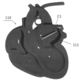
- FIG. 1 is a diagram showing a human body model 100 of the present embodiment.
- the human body model 100 is a surgical simulator for a user to perform a surgical simulation.
- the user is a surgeon such as a young surgeon or a skilled surgeon.
- the human body model 100 has a heart model 110 and a blood vessel model 120.
- the heart model 110 is an organ model simulating a human heart.
- the blood vessel model 120 is an organ model that imitates a human blood vessel.
- the blood vessel model 120 can flow a fluid close to blood.
- the material of the heart model 110 is a silicone resin or a hydrogel resin.
- the material of the blood vessel model 120 is a silicone resin or a hydrogel resin.
- the human body model 100, the heart model 110, and the blood vessel model 120 are made of transparent resin.
- the heart model 110 is a target organ model for performing a surgical simulation involving heat treatment such as catheter ablation.
- the heart model 110 has a temperature indicator 111.
- the temperature indicator 111 has a film shape.
- the temperature indicator 111 is affixed to the inner surface of the heart model 110.
- the temperature indicator 111 may be affixed to the outer surface of the heart model 110.
- the temperature indicator 111 contains polydimethylsiloxane (PDMS) and a thermochromic pigment.
- PDMS polydimethylsiloxane
- the thermochromic pigment is usually a material that is almost transparent and develops color at a temperature equal to or higher than the lower limit temperature of the saturation increasing region inherent to the pigment. The lower limit temperature of the saturation increasing region will be described later.
- thermochromic pigments are classified into irreversible materials that remain colored once they have developed color, and reversible materials that develop color above the lower temperature limit of the saturation increase region and return to the original transparent color after cooling.
- the thermochromic pigment of this embodiment is an irreversible material. That is, once the color is developed, it does not return to the original transparent color.
- the ratio of the thermochromic pigment in the temperature indicator 111 is 0.5 wt% or more and 4 wt% or less. When it is within this range, the temperature indicator 111 after color development is translucent.
- the proportion of the thermochromic pigment in the temperature indicator 111 is 1 wt% or more and 3.5 wt% or less. More preferably, the ratio of the thermochromic pigment in the temperature indicator 111 is 1 wt% or more and 2.5 wt% or less.
- thermochromic pigment of this embodiment develops is magenta.
- the color that the thermochromic pigment develops may be other colors.
- Thermal conductivity of temperature indicator The thermal conductivity of the temperature indicator 111 is close to the thermal conductivity of an actual human body.
- polydimethylsiloxane PDMS
- the thermal conductivity (representative value) of the skin is 0.21 W / mK.
- the thermal conductivity (representative value) of muscle is 0.40 W / mK.
- thermochromic pigments are in liquid or powder form. Therefore, the mixed material is liquid.
- the ratio of the thermochromic pigment in the mixed material is 0.5 wt% or more and 4 wt% or less. Then, the mixed material is applied to the surface of the heart model 110.
- the heart model 110 to which the mixed material is applied is heated. For example, heating in an oven.
- the heating temperature is, for example, 30 ° C.
- the heart model 110 provided with the temperature indicator 111 is manufactured.
- a heating process may be unnecessary. That is, the heart model 110 can be manufactured by natural drying.
- a surgical simulation method using the heart model 110 shown in FIG. 2 will be described.
- a liquid is passed through the blood vessel model 130. This is because the simulation is performed including the effects of blood.
- the catheter C ⁇ b> 1 is inserted into the heart model 110.
- the target location A1 is heated by the high frequency with the front-end
- a temperature indicator 111 is formed around the target location A1.
- tip C1a of the catheter C1 heats the target location A1 of the heart model 110.
- the temperature of target location A1 rises. Then, heat is conducted around the target location A1.
- the target temperature of the heating temperature is 70 ° C. This is because the actual living body tissue can be necrotized by heating to 70 ° C. When the temperature of the living tissue reaches about 80 ° C., the living tissue is burned. Therefore, it is preferable that the temperature of the target location A1 and its surroundings is about 70 ° C. and lower than 80 ° C.
- a high-frequency heater and a temperature sensor are disposed at the distal end C1a of the catheter C1.
- the tip C1a of the catheter C1 has reached a temperature sufficiently higher than the actual temperature of the heart model 110. Therefore, with this temperature sensor, it is impossible to measure what temperature distribution actually occurs in the heart model 110.
- the temperature indicator 111 is colored near 70 ° C. Therefore, the user can grasp the target location A1 and the temperature around it by the temperature indicator 111.
- the user can determine whether or not the target location A1 can be heat-treated by catheter ablation by performing a surgical simulation using the heart model 110 of this embodiment. Even when the user is performing heat treatment, the color of the temperature indicator 111 does not interfere with the simulation. This is because the temperature indicator 111 after color development is translucent. Thus, the heart model 110 of this embodiment can visualize the temperature distribution.
- the user can measure the processing time for actually heat-treating the target location A1. Depending on how much time is required for heat treatment, the user can grasp at which processing time the target location A1 has reached the target temperature.
- the temperature indicator 111 has a film shape.
- the temperature indicator 111 can leave a temperature history in the film thickness direction. That is, by observing the cross section of the temperature indicator 111 after use, the user can determine a three-dimensional temperature history. Thus, the temperature indicator 111 can visualize a three-dimensional temperature distribution.
- Experiment 7-1 Temperature dependence of color First, a sample was prepared. This sample is a temperature indicator in which polydimethylsiloxane (PDMS) is mixed with 4 wt% thermochromic pigment (manufactured by Tosco Corporation). And the image was acquired using the video camera, heating this sample uniformly in oven.
- PDMS polydimethylsiloxane
- Fig. 4 is an image of the temperature indicator at 47 ° C.
- FIG. 5 is an image of the temperature indicator at 68 ° C.
- FIG. 6 is an image of the temperature indicator at 94 ° C.
- FIG. 7 is an image of a temperature indicator at 115 ° C. As shown in FIGS. 4 to 7, the color of the temperature indicator becomes darker as the temperature of the temperature indicator increases. Note that the color of the temperature indicator shown in FIGS. 4 to 7 is magenta. This temperature indicator is translucent even after color development.
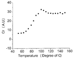
- FIG. 8 is a graph showing the relationship between the temperature of the temperature indicator and the red color difference Cr in the YCrCb color space.
- the red color difference Cr greatly changes in the temperature range from 60 ° C. to 100 ° C. Therefore, the color change of the temperature indicator is remarkable in this temperature region. That is, this sample can detect the temperature change in this temperature range suitably.
- FIG. 9 is a graph showing the relationship between the temperature of the temperature indicator and the saturation S in the HSV color space. As shown in FIG. 9, the saturation S changes greatly in the temperature range from 60 ° C. to 110 ° C. Therefore, the color change of the temperature indicator is remarkable in this temperature region. That is, this sample can detect the temperature change in this temperature range suitably.
- the saturation increase region J is a region where the saturation S of the HSV color space in the temperature indicator simply increases. As shown in FIG. 9, the saturation increase region J is in the range of 60 ° C. or higher and 110 ° C. or lower. In the saturation increase region J, the saturation S increases as the temperature of the temperature indicator increases. In FIG. 9, the lower limit temperature J1 of the saturation increasing region J is 60 ° C.
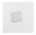
- FIG. 10 is an image showing a temperature indicator at room temperature. As shown in FIG. 10, the temperature indicator is translucent.
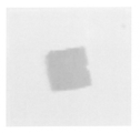
- FIG. 11 is an image showing a temperature indicator heated to 70 ° C. As shown in FIG. 11, the temperature indicator changes to magenta, but remains translucent. Thus, even if the temperature of the temperature indicator changes, the temperature indicator remains translucent.
- the human body model 100 has a model of each organ.
- the human body model 100 in FIG. 1 has a shape that imitates the whole body of a person. However, it is sufficient if the surgeon can simulate the operation. Therefore, not the whole body as shown in FIG. That is, the human body model only needs to reproduce at least a part of the human body.
- PDMS polydimethylsiloxane
- other resins may be used as the resin for the temperature indicator 111.
- this resin is preferably a transparent resin. This is because it is easy for the user to visually observe the medical instrument and the affected part in the simulation of the operation.
- the transparent resin is, for example, a silicone resin or a hydrogel resin.
- the temperature indicator 111 may contain two types of irreversible thermochromic pigments.
- the temperature indicator 111 has a first irreversible thermochromic pigment and a second irreversible thermochromic pigment.
- the lower limit temperature of the saturation increase region of the second irreversible thermochromic pigment is higher than the lower limit temperature of the saturation increase region of the first irreversible thermochromic pigment.
- the first irreversible thermochromic pigment develops color at a temperature of 45 ° C. or higher and 75 ° C. or lower.
- the second irreversible thermochromic pigment develops color at a temperature of 80 ° C. or higher and 110 ° C. or lower.
- the color of the first irreversible thermochromic pigment is light yellowish green.
- the color of the second irreversible thermochromic pigment is magenta.
- the user performs heat treatment based on the pale yellowish green color of the first irreversible thermochromic pigment. Therefore, when the temperature of the heat treatment rises too much, that portion becomes magenta.
- the color is a mixture of magenta and yellow-green. In this way, thermal damage has occurred due to catheter ablation at the location where magenta is colored. That is, after finishing the simulation, evaluation is made as to whether (1) the target location A1 can be reliably heat-treated, and (2) whether other locations are thermally damaged by the catheter C1. be able to.
- the lower limit temperature of the saturation increase region of the second irreversible thermochromic pigment is higher than the lower limit temperature of the saturation increase region of the first irreversible thermochromic pigment.
- the lower limit temperature of the saturation increasing region of the first irreversible thermochromic pigment is 45 ° C.
- the lower limit temperature of the saturation increase region of the second irreversible thermochromic pigment is 80 ° C.
- the color strength of the second irreversible thermochromic pigment may be darker than the color strength of the first irreversible thermochromic pigment. This is because it is easy to visually determine a portion of the heart model 110 where the temperature has increased excessively.
- the total ratio of the plurality of types of thermochromic pigments in the temperature indicator is 0.5 wt% or more and 4 wt% or less.
- the temperature indicator 111 may contain one type of reversible thermochromic pigment.
- the first reversible thermochromic pigment develops color at a temperature of 65 ° C. or higher and 75 ° C. or lower.
- the color of the first reversible thermochromic pigment is light yellowish green.
- the temperature indicator 111 may contain two types of reversible thermochromic pigments.
- the temperature indicator 111 includes a first reversible thermochromic pigment and a second reversible thermochromic pigment.
- the lower limit temperature of the saturation increase region of the second reversible thermochromic pigment is higher than the lower limit temperature of the saturation increase region of the first reversible thermochromic pigment.
- the first reversible thermochromic pigment develops color at a temperature of 65 ° C. or higher and 75 ° C. or lower.
- the second reversible thermochromic pigment develops color at a temperature of 80 ° C. or higher and 85 ° C. or lower.
- the color of the first reversible thermochromic pigment is light yellowish green.
- the color of the second reversible thermochromic pigment is magenta.
- the temperature indicator 111 may contain one type of reversible thermochromic pigment and one type of irreversible thermochromic pigment.
- the temperature indicator 111 includes a first reversible thermochromic pigment and a first irreversible thermochromic pigment.
- the lower limit temperature of the saturation increase region of the first irreversible thermochromic pigment is higher than the lower limit temperature of the saturation increase region of the first reversible thermochromic pigment.
- the first reversible thermochromic pigment develops color at a temperature of 65 ° C. or higher and 75 ° C. or lower.
- the first irreversible thermochromic pigment develops color at a temperature of 80 ° C. or higher and 85 ° C. or lower.
- the color of the first reversible thermochromic pigment is light yellowish green.
- the color of the first irreversible thermochromic pigment is magenta.
- the user can grasp the target location A1 and the surrounding temperature in real time, and can evaluate a location that seems to have been thermally damaged after the surgical simulation.
- Integral molded organ model A temperature indicator 111 is attached to the surface of the heart model 110 of the present embodiment.
- the heart model may be integrally molded by mixing a thermochromic pigment with the heart model itself. That is, the temperature indicator 111 is integrally formed with the organ model.
- the organ model of this embodiment is a heart model 110.
- the human body model 100 may have other organ models.
- a kidney model, a liver model, a lung model, etc. are mentioned.
- the temperature indicator 111 can be replaced. That is, the temperature indicator 111 that has been used and has developed color is peeled off from the heart model 110, and a new temperature indicator 111 may be attached to the heart model 110.
- the sheet-like temperature indicator 111 can be easily attached to the resin. Thereby, the surgery simulation can be repeatedly performed.
- thermochromic pigment color The color of the thermochromic pigment is exemplary. Therefore, the color of the thermochromic pigment may be a color other than the colors listed above.
- the heart model 110 of this embodiment has a temperature indicator 111.
- the temperature indicator 111 contains a resin and a thermochromic pigment. Therefore, when the user performs a surgical simulation using the heart model 110, the user can perform the operation while grasping the temperature state of the heart model 110. Thereby, the organ model which can judge the quality of the result of a surgery simulation is implement
- the temperature indicator patch of the second embodiment is a patch for mounting on the heart model 110 of the first embodiment.
- Temperature Indicator Patch This temperature indicator patch is similar to the temperature indicator 111. Therefore, the temperature indicator patch contains a transparent resin and a thermochromic pigment. The proportion of the thermochromic pigment in the temperature indicator patch is 0.5 wt% or more and 4 wt% or less.
- the temperature indicator patch is sticky. Therefore, it is easy to apply the temperature indicator patch to the heart model 110. It is also easy to remove the temperature indicator patch from the heart model 110 after use.
- the temperature indicator patch according to the present embodiment can be attached to an organ model of a conventional human body model. Accordingly, the user can perform a rehearsal of an operation such as catheter ablation with respect to an operation simulator that does not assume heat treatment such as catheter ablation.
Landscapes
- Engineering & Computer Science (AREA)
- Physics & Mathematics (AREA)
- General Physics & Mathematics (AREA)
- Chemical & Material Sciences (AREA)
- Manufacturing & Machinery (AREA)
- Materials Engineering (AREA)
- Algebra (AREA)
- Mathematical Optimization (AREA)
- Medical Informatics (AREA)
- Medicinal Chemistry (AREA)
- Health & Medical Sciences (AREA)
- Computational Mathematics (AREA)
- Mathematical Analysis (AREA)
- General Health & Medical Sciences (AREA)
- Mathematical Physics (AREA)
- Pure & Applied Mathematics (AREA)
- Business, Economics & Management (AREA)
- Educational Administration (AREA)
- Educational Technology (AREA)
- Theoretical Computer Science (AREA)
- Mechanical Engineering (AREA)
- Instructional Devices (AREA)
Abstract
【課題】 使用者が、手術シミュレーターの実体モデルの温度状態を把握することの可能な臓器モデルとその製造方法および温度インジケータパッチを提供することである。 【解決手段】 人体モデル(100)は、心臓モデル(110)と、血管モデル(120)と、を有している。心臓モデル(110)は、心臓を模った臓器モデルである。心臓モデル(110)は、温度インジケータ(111)を有する。温度インジケータ(111)は、透明性の樹脂と、サーモクロミック顔料と、を含有する。
Description
本明細書の技術分野は、医者が手術のシミュレーションに用いる臓器モデルとその製造方法および温度インジケータパッチに関する。
近年、医療技術が高度化および複雑化している。それに伴って、外科医に要求される技術も高度化および多様化している。そのため、手術シミュレーターが用いられることがある。これにより、若手執刀医は訓練を行うことができる。また、熟練の執刀医も手術前のリハーサルを行うことができる。
手術シミュレーターには、CG等を駆使したバーチャルシミュレーターと、臓器の形状を模った実体モデルを用いたシミュレーターと、の2種類がある。バーチャルシミュレーターは、仮想的に様々な環境および条件を設定できる点で優れている。実体モデルを用いたシミュレーターは、手術中の感触等を体験できる点で優れている。特許文献1には、実体モデルを用いたシミュレーターとして、人体モデルが開示されている。
このような実体モデルを用いたシミュレーターでは、より現実的な造形および質感が求められている。実体モデルの形状については、3Dプリンターの発展により、高精度な臓器モデルを製造できるようになってきている。
一方、人体に損傷を与えるおそれのある手術についてシミュレーションをする場合には、より現実的な反応を実体モデルから得られることが好ましい。人体に損傷を与えるおそれのある手術として、例えば、カテーテルアブレーション治療のような熱処理を実施する手術が挙げられる。カテーテルアブレーション治療では、例えば、心臓の不整脈の原因となっている箇所を高周波で焼き切る。その場合には、目的箇所のみを焼き切ることが好ましい。しかし、実際にはその周辺の生体組織にも熱を与えてしまうおそれがある。したがって、実体モデルを用いる場合であっても、実体モデルにどの程度の熱的ダメージを与えたのか、使用者が判断できることが好ましい。
本明細書の技術は、前述した従来の技術が有する問題点を解決するためになされたものである。すなわちその課題とするところは、使用者が、手術シミュレーターの実体モデルの温度状態を把握することの可能な臓器モデルとその製造方法および温度インジケータパッチを提供することである。
第1の態様における臓器モデルは、温度インジケータを有する。温度インジケータは、透明性の樹脂と、サーモクロミック顔料と、を含有する。
この臓器モデルでは、サーモクロミック顔料が彩度上昇領域の下限温度に達したときに発色する。それに伴って、この温度インジケータは発色する。そのため、例えば、カテーテルアブレーション治療等のシミュレーションをする場合に、使用者は、臓器モデルに対する熱履歴を把握することができる。つまり、使用者は、臓器モデルを用いてシミュレーションをしている最中に、熱処理をする目的箇所およびその周囲についてどの程度の温度分布となるかを把握することができる。つまり、臓器モデルの温度履歴が可視化されている。
第2の態様における臓器モデルにおいては、温度インジケータに占めるサーモクロミック顔料の割合は、0.5wt%以上4wt%以下である。この温度インジケータの発色後の色は、半透明である。そのため、温度インジケータが発色した後であっても、使用者は、温度インジケータに妨げられることなく手術のシミュレーションを続行することができる。
第3の態様における臓器モデルにおいては、透明性の樹脂は、シリコーン系樹脂もしくはハイドロゲル系樹脂である。そのため、この臓器モデルの質感は、実際の人体にある程度近い。
第4の態様における臓器モデルにおいては、温度インジケータは、第1の不可逆性のサーモクロミック顔料と、第2の不可逆性のサーモクロミック顔料と、を有する。第2の不可逆性のサーモクロミック顔料の彩度上昇領域の下限温度は、第1の不可逆性のサーモクロミック顔料の彩度上昇領域の下限温度よりも高い。そのため、使用者は、第1の不可逆性のサーモクロミック顔料の発色により、目的箇所が好適な熱処理温度に達していることを把握できる。また、使用者は、第2の不可逆性のサーモクロミック顔料の発色により、目的箇所の周辺の温度が高くなりすぎていることを把握できる。
第5の態様における臓器モデルにおいては、温度インジケータは、第1の可逆性のサーモクロミック顔料と、第2の可逆性のサーモクロミック顔料と、を有する。第2の可逆性のサーモクロミック顔料の彩度上昇領域の下限温度は、第1の可逆性のサーモクロミック顔料の彩度上昇領域の下限温度よりも高い。そのため、使用者は、第1の可逆性のサーモクロミック顔料の発色により、目的箇所が好適な熱処理温度に達していることを把握できる。また、使用者は、第2の可逆性のサーモクロミック顔料の発色により、目的箇所の周辺の温度が高くなりすぎていることを把握できる。そして、使用者は、目的箇所の温度をリアルタイムで把握できる。
第6の態様における臓器モデルにおいては、温度インジケータは、第1の可逆性のサーモクロミック顔料と、第1の不可逆性のサーモクロミック顔料と、を有する。第1の不可逆性のサーモクロミック顔料の彩度上昇領域の下限温度は、第1の可逆性のサーモクロミック顔料の彩度上昇領域の下限温度よりも高い。そのため、使用者は、第1の可逆性のサーモクロミック顔料の発色により、目的箇所が好適な熱処理温度に達していることを把握できる。また、使用者は、第1の不可逆性のサーモクロミック顔料の発色により、目的箇所の周辺の温度が高くなりすぎていることを把握できる。そして、使用者は、目的箇所の温度をリアルタイムで把握できるとともに、シミュレーションの終了後に温度が高くなりすぎた箇所について評価することができる。
第7の態様における臓器モデルにおいては、温度インジケータは、臓器モデルと一体成型されている。
第8の態様における臓器モデルの製造方法は、臓器モデルを造形する造形工程と、透明性の樹脂とサーモクロミック顔料とを混合した混合材料を臓器モデルに塗布する塗布工程と、を有する。
第9の態様における臓器モデルの製造方法においては、塗布工程では、混合材料に占めるサーモクロミック顔料の割合を、0.5wt%以上4wt%以下とする。
第10の態様における臓器モデルの製造方法においては、透明性の樹脂は、シリコーン系樹脂もしくはハイドロゲル系樹脂である。
第11の態様における臓器モデルの製造方法においては、塗布工程では、透明性の樹脂と、第1の不可逆性のサーモクロミック顔料と、第2の不可逆性のサーモクロミック顔料と、を混合して混合材料とする。第2の不可逆性のサーモクロミック顔料の彩度上昇領域の下限温度は、第1の不可逆性のサーモクロミック顔料の彩度上昇領域の下限温度よりも高い。
第12の態様における臓器モデルの製造方法においては、塗布工程では、透明性の樹脂と、第1の可逆性のサーモクロミック顔料と、第2の可逆性のサーモクロミック顔料と、を混合して混合材料とする。第2の可逆性のサーモクロミック顔料の彩度上昇領域の下限温度は、第1の可逆性のサーモクロミック顔料の彩度上昇領域の下限温度よりも高い。
第13の態様における臓器モデルの製造方法においては、塗布工程では、透明性の樹脂と、第1の可逆性のサーモクロミック顔料と、第1の不可逆性のサーモクロミック顔料と、を混合して混合材料とする。第1の不可逆性のサーモクロミック顔料の彩度上昇領域の下限温度は、第1の可逆性のサーモクロミック顔料の彩度上昇領域の下限温度よりも高い。
第14の態様における温度インジケータパッチは、臓器モデルに装着するためのものである。この温度インジケータは、透明性の樹脂とサーモクロミック顔料とを含有する。温度インジケータパッチに占めるサーモクロミック顔料の割合は、0.5wt%以上4wt%以下である。この温度インジケータパッチを使用することにより、既存の臓器モデルを用いて熱処理を伴う手術のシミュレーションを好適に行うことができる。
本明細書では、使用者が、手術シミュレーターの実体モデルの温度状態を把握することの可能な臓器モデルとその製造方法および温度インジケータパッチが提供されている。
以下、実施形態について添付図面を参照しつつ説明する。以下の実施形態では、臓器モデルとその製造方法および温度インジケータパッチについて説明する。臓器モデルは、例示であり、実施形態に示されているものに限定されない。
(第1の実施形態)
1.人体モデル(手術シミュレーター)
図1は、本実施形態の人体モデル100を示す図である。人体モデル100は、使用者が手術のシミュレーションを実施するための手術シミュレーターである。ここで、使用者とは、若手執刀医や熟練した執刀医等の外科医である。
1.人体モデル(手術シミュレーター)
図1は、本実施形態の人体モデル100を示す図である。人体モデル100は、使用者が手術のシミュレーションを実施するための手術シミュレーターである。ここで、使用者とは、若手執刀医や熟練した執刀医等の外科医である。
人体モデル100は、心臓モデル110と、血管モデル120と、を有している。図2に示すように、心臓モデル110は、人間の心臓を模った臓器モデルである。血管モデル120は、人間の血管を模った臓器モデルである。血管モデル120には、血液に近い流体を流すことができる。心臓モデル110の材質は、シリコーン系樹脂もしくはハイドロゲル系樹脂である。血管モデル120の材質は、シリコーン系樹脂もしくはハイドロゲル系樹脂である。このように、人体モデル100と、心臓モデル110と、血管モデル120とは、透明性の樹脂からできている。
2.温度インジケータ
心臓モデル110は、カテーテルアブレーション等の熱処理を伴う手術シミュレーションを実施するための目標となる臓器モデルである。心臓モデル110は、温度インジケータ111を有する。温度インジケータ111は、膜状である。温度インジケータ111は、心臓モデル110の内側の表面に貼り付けられている。温度インジケータ111は、もちろん、心臓モデル110の外側の表面に貼り付けられていてもよい。温度インジケータ111は、ポリジメチルシロキサン(PDMS)と、サーモクロミック顔料と、を含有している。ここで、サーモクロミック顔料は、通常はほぼ透明であり、その顔料に固有の彩度上昇領域の下限温度以上で発色する材料である。彩度上昇領域の下限温度については、後述する。
心臓モデル110は、カテーテルアブレーション等の熱処理を伴う手術シミュレーションを実施するための目標となる臓器モデルである。心臓モデル110は、温度インジケータ111を有する。温度インジケータ111は、膜状である。温度インジケータ111は、心臓モデル110の内側の表面に貼り付けられている。温度インジケータ111は、もちろん、心臓モデル110の外側の表面に貼り付けられていてもよい。温度インジケータ111は、ポリジメチルシロキサン(PDMS)と、サーモクロミック顔料と、を含有している。ここで、サーモクロミック顔料は、通常はほぼ透明であり、その顔料に固有の彩度上昇領域の下限温度以上で発色する材料である。彩度上昇領域の下限温度については、後述する。
サーモクロミック顔料には、一度発色するとその発色したままの不可逆性の材料と、彩度上昇領域の下限温度以上で発色するとともに降温後には元の透明色に戻る可逆性の材料と、がある。本実施形態のサーモクロミック顔料は、不可逆性の材料である。すなわち、一度発色した後には元の透明色に戻ることはない。
本実施形態では、温度インジケータ111に占めるサーモクロミック顔料の割合は、0.5wt%以上4wt%以下である。この範囲内のときに、発色後の温度インジケータ111は、半透明である。好ましくは、温度インジケータ111に占めるサーモクロミック顔料の割合は、1wt%以上3.5wt%以下である。より好ましくは、温度インジケータ111に占めるサーモクロミック顔料の割合は、1wt%以上2.5wt%以下である。
本実施形態のサーモクロミック顔料が発色する色は、マゼンタである。もちろん、サーモクロミック顔料が発色する色は、その他の色であってもよい。
3.温度インジケータの熱伝導率
温度インジケータ111の熱伝導率は、実際の人体の熱伝導率に近い。例えば、ポリジメチルシロキサン(PDMS)の熱伝導率は、0.27W/mKである。皮膚の熱伝導率(代表値)は、0.21W/mKである。筋肉の熱伝導率(代表値)は、0.40W/mKである。
温度インジケータ111の熱伝導率は、実際の人体の熱伝導率に近い。例えば、ポリジメチルシロキサン(PDMS)の熱伝導率は、0.27W/mKである。皮膚の熱伝導率(代表値)は、0.21W/mKである。筋肉の熱伝導率(代表値)は、0.40W/mKである。
4.人体モデルの製造方法
4-1.造形工程
まず、臓器モデルを造形する。そのために、例えば、3Dプリンターを用いればよい。そして、心臓モデル110と血管モデル120とを製作する。また、人体モデル100の本体を製作する。
4-1.造形工程
まず、臓器モデルを造形する。そのために、例えば、3Dプリンターを用いればよい。そして、心臓モデル110と血管モデル120とを製作する。また、人体モデル100の本体を製作する。
4-2.塗布工程
次に、ポリジメチルシロキサン(PDMS)とサーモクロミック顔料とを混合した混合材料を準備する。ポリジメチルシロキサン(PDMS)は、液体である。サーモクロミック顔料は、液体もしくは粉末状である。そのため、混合材料は、液状である。ここで混合材料に占めるサーモクロミック顔料の割合を、0.5wt%以上4wt%以下とする。そして、その混合材料を心臓モデル110の表面に塗布する。
次に、ポリジメチルシロキサン(PDMS)とサーモクロミック顔料とを混合した混合材料を準備する。ポリジメチルシロキサン(PDMS)は、液体である。サーモクロミック顔料は、液体もしくは粉末状である。そのため、混合材料は、液状である。ここで混合材料に占めるサーモクロミック顔料の割合を、0.5wt%以上4wt%以下とする。そして、その混合材料を心臓モデル110の表面に塗布する。
4-3.加熱工程
この混合材料を塗布した心臓モデル110を加熱する。例えば、オーブンで加熱する。加熱温度は、例えば、30℃である。これにより、温度インジケータ111を備える心臓モデル110が製作される。なお、加熱工程は不要の場合がある。つまり、自然乾燥により、心臓モデル110を製造することもできる。
この混合材料を塗布した心臓モデル110を加熱する。例えば、オーブンで加熱する。加熱温度は、例えば、30℃である。これにより、温度インジケータ111を備える心臓モデル110が製作される。なお、加熱工程は不要の場合がある。つまり、自然乾燥により、心臓モデル110を製造することもできる。
4-4.組立工程
この後、心臓モデル110および血管モデル120を人体モデル100の本体に収容する。これにより、人体モデル100が製造される。
この後、心臓モデル110および血管モデル120を人体モデル100の本体に収容する。これにより、人体モデル100が製造される。
5.人体モデルの使用方法(手術のシミュレーション)
図2に示す心臓モデル110を用いた手術のシミュレーション方法について説明する。このとき、血管モデル130には液体を流す。血液による効果を含めてシミュレーションを実施するためである。図2および図3に示すように、カテーテルC1を心臓モデル110に挿入する。そして、カテーテルC1の先端C1aで目標箇所A1を高周波により加熱する。ここで、目標箇所A1の周囲には温度インジケータ111が形成されている。
図2に示す心臓モデル110を用いた手術のシミュレーション方法について説明する。このとき、血管モデル130には液体を流す。血液による効果を含めてシミュレーションを実施するためである。図2および図3に示すように、カテーテルC1を心臓モデル110に挿入する。そして、カテーテルC1の先端C1aで目標箇所A1を高周波により加熱する。ここで、目標箇所A1の周囲には温度インジケータ111が形成されている。
そして、図3に示すように、カテーテルC1の先端C1aは、心臓モデル110の目標箇所A1を加熱する。これにより、目標箇所A1の温度は上昇する。そして、熱は目標箇所A1の周囲に伝導する。
ここで、加熱温度の目標温度は70℃である。70℃まで加熱することにより、実際の人体の生体組織を壊死させることができるからである。生体組織の温度が80℃程度になると、生体組織は火傷する。したがって、目標箇所A1およびその周辺の温度を70℃程度にするとともに80℃未満にすることが好ましい。
なお、カテーテルC1の先端C1aには、高周波加熱器および温度センサが配置されている。しかし、カテーテルC1の先端C1aは、心臓モデル110の実際の温度に比べて十分に高い温度に達していると考えられる。そのため、この温度センサでは、心臓モデル110に実際にどのような温度分布が生じているのか測定することはできない。
本実施形態の心臓モデル110では、温度インジケータ111は、70℃近傍で発色する。そのため、使用者は、温度インジケータ111により、目標箇所A1およびその周辺の温度を把握することができる。
6.本実施形態の効果
使用者は、本実施形態の心臓モデル110を用いて手術のシミュレーションを行うことにより、カテーテルアブレーションで目標箇所A1を熱処理することができたか判断することができる。また、使用者が熱処理を行っている最中であっても、温度インジケータ111の発色がシミュレーションの邪魔にならない。発色後の温度インジケータ111は、半透明だからである。このように、本実施形態の心臓モデル110は、温度分布を可視化することができる。
使用者は、本実施形態の心臓モデル110を用いて手術のシミュレーションを行うことにより、カテーテルアブレーションで目標箇所A1を熱処理することができたか判断することができる。また、使用者が熱処理を行っている最中であっても、温度インジケータ111の発色がシミュレーションの邪魔にならない。発色後の温度インジケータ111は、半透明だからである。このように、本実施形態の心臓モデル110は、温度分布を可視化することができる。
また、使用者は、実際に目標箇所A1を熱処理する処理時間を計測することができる。どの程度の時間をかけて熱処理をするかによって、使用者は、目標箇所A1がどの処理時間で目標温度に達しているか把握することができる。
前述したように、温度インジケータ111は、膜状である。そして、この温度インジケータ111は、膜厚方向の温度履歴を残すことができる。つまり、使用後に温度インジケータ111の断面を観察することにより、使用者は、3次元的な温度履歴を判断することができる。このように、温度インジケータ111は、3次元的な温度分布を可視化することができる。
7.実験
7-1.色の温度依存性
まず、試料を作製した。この試料は、ポリジメチルシロキサン(PDMS)に4wt%のサーモクロミック顔料(トスコ社製)を混合した温度インジケータである。そして、この試料をオーブンで均一に加熱しながらビデオカメラを用いて画像を取得した。
7-1.色の温度依存性
まず、試料を作製した。この試料は、ポリジメチルシロキサン(PDMS)に4wt%のサーモクロミック顔料(トスコ社製)を混合した温度インジケータである。そして、この試料をオーブンで均一に加熱しながらビデオカメラを用いて画像を取得した。
図4は、47℃のときの温度インジケータの画像である。図5は、68℃のときの温度インジケータの画像である。図6は、94℃のときの温度インジケータの画像である。図7は、115℃のときの温度インジケータの画像である。図4から図7までに示すように、温度インジケータの温度が上昇するにしたがって、温度インジケータの色は濃くなる。なお、図4から図7までに示す温度インジケータの色は、マゼンタである。そして、この温度インジケータは、発色後も半透明である。
図8は、温度インジケータの温度とYCrCb色空間における赤の色差Crとの関係を示すグラフである。図8に示すように、60℃から100℃にかけての温度範囲で、赤の色差Crが大きく変化している。そのため、この温度領域では、温度インジケータの色の変化が顕著である。つまり、この試料は、この温度領域における温度変化を好適に検知することができる。
図9は、温度インジケータの温度とHSV色空間における彩度Sとの関係を示すグラフである。図9に示すように、60℃から110℃にかけての温度範囲で、彩度Sが大きく変化している。そのため、この温度領域では、温度インジケータの色の変化が顕著である。つまり、この試料は、この温度領域における温度変化を好適に検知することができる。
彩度上昇領域Jは、温度インジケータにおけるHSV色空間の彩度Sが単純に上昇している領域である。図9に示すように、彩度上昇領域Jは、60℃以上110℃以下の範囲内である。彩度上昇領域Jでは、彩度Sは、温度インジケータの温度の上昇とともに増加している。図9では、彩度上昇領域Jの下限温度J1は、60℃である。
7-2.半透明性
図10は、常温における温度インジケータを示す画像である。図10に示すように温度インジケータは半透明である。図11は、70℃に加熱した温度インジケータを示す画像である。図11に示すように、温度インジケータは、マゼンタに変色しているが、半透明を維持している。このように、温度インジケータの温度が変化しても、温度インジケータは、半透明を維持している。
図10は、常温における温度インジケータを示す画像である。図10に示すように温度インジケータは半透明である。図11は、70℃に加熱した温度インジケータを示す画像である。図11に示すように、温度インジケータは、マゼンタに変色しているが、半透明を維持している。このように、温度インジケータの温度が変化しても、温度インジケータは、半透明を維持している。
8.変形例
8-1.人体モデル
本実施形態では、人体モデル100が各臓器のモデルを有している。図1の人体モデル100は、人の全身を模った形状を有している。しかし、外科医が手術のシミュレーションをすることができれば十分である。そのため、図1に示すような全身でなく、例えば、胴体部分だけであってもよい。つまり、人体モデルは、人体の少なくとも一部を再現したものであればよい。
8-1.人体モデル
本実施形態では、人体モデル100が各臓器のモデルを有している。図1の人体モデル100は、人の全身を模った形状を有している。しかし、外科医が手術のシミュレーションをすることができれば十分である。そのため、図1に示すような全身でなく、例えば、胴体部分だけであってもよい。つまり、人体モデルは、人体の少なくとも一部を再現したものであればよい。
8-2.温度インジケータの樹脂の種類
本実施形態では、温度インジケータ111の樹脂としてポリジメチルシロキサン(PDMS)を用いる。しかし、温度インジケータ111の樹脂としてその他の樹脂を用いてもよい。ただし、この樹脂は、透明性の樹脂であるとよい。手術のシミュレーションにおいて、使用者が医療器具や患部を目視しやすいからである。透明性の樹脂は、例えば、シリコーン系樹脂もしくはハイドロゲル系樹脂である。
本実施形態では、温度インジケータ111の樹脂としてポリジメチルシロキサン(PDMS)を用いる。しかし、温度インジケータ111の樹脂としてその他の樹脂を用いてもよい。ただし、この樹脂は、透明性の樹脂であるとよい。手術のシミュレーションにおいて、使用者が医療器具や患部を目視しやすいからである。透明性の樹脂は、例えば、シリコーン系樹脂もしくはハイドロゲル系樹脂である。
8-3.2種類の不可逆性のサーモクロミック顔料
温度インジケータ111は、2種類の不可逆性のサーモクロミック顔料を含有してもよい。この場合、温度インジケータ111は、第1の不可逆性のサーモクロミック顔料と、第2の不可逆性のサーモクロミック顔料と、を有する。第2の不可逆性のサーモクロミック顔料の彩度上昇領域の下限温度は、第1の不可逆性のサーモクロミック顔料の彩度上昇領域の下限温度よりも高い。
温度インジケータ111は、2種類の不可逆性のサーモクロミック顔料を含有してもよい。この場合、温度インジケータ111は、第1の不可逆性のサーモクロミック顔料と、第2の不可逆性のサーモクロミック顔料と、を有する。第2の不可逆性のサーモクロミック顔料の彩度上昇領域の下限温度は、第1の不可逆性のサーモクロミック顔料の彩度上昇領域の下限温度よりも高い。
例えば、第1の不可逆性のサーモクロミック顔料は、45℃以上75℃以下の温度で発色する。第2の不可逆性のサーモクロミック顔料は、80℃以上110℃以下の温度で発色する。例えば、第1の不可逆性のサーモクロミック顔料の色は、薄い黄緑色である。第2の不可逆性のサーモクロミック顔料の色は、マゼンタである。これらの色は例示であるが、第1の不可逆性のサーモクロミック顔料の色と第2の不可逆性のサーモクロミック顔料の色とは、互いに異なる色であるとよい。
これにより、使用者は、第1の不可逆性のサーモクロミック顔料の薄い黄緑色を基準に熱処理を行う。そこで、熱処理の温度が上昇しすぎた場合には、その部分がマゼンタになる。実際には、マゼンタと黄緑色とが混じった色となる。このように、マゼンタが発色している箇所には、カテーテルアブレーションにより熱的ダメージが発生していることとなる。つまり、シミュレーションを終えた後に、(1)目標箇所A1を確実に熱処理することができたかどうか、(2)カテーテルC1によりその他の箇所に熱的損傷を与えなかったかどうか、という点について、評価することができる。
なお、第2の不可逆性のサーモクロミック顔料の彩度上昇領域の下限温度は、第1の不可逆性のサーモクロミック顔料の彩度上昇領域の下限温度よりも高い。上記の例では、第1の不可逆性のサーモクロミック顔料の彩度上昇領域の下限温度は、45℃である。第2の不可逆性のサーモクロミック顔料の彩度上昇領域の下限温度は、80℃である。これにより、温度インジケータ111は、2段階に発色する。
そして、第2の不可逆性のサーモクロミック顔料の色の濃さは、第1の不可逆性のサーモクロミック顔料の色の濃さよりも濃いとよい。心臓モデル110において温度が上昇しすぎた箇所を目視により判断しやすいからである。
このように、複数種類のサーモクロミック顔料を用いて温度インジケータを製造する場合において、温度インジケータに占める複数種類のサーモクロミック顔料の割合の合計は、0.5wt%以上4wt%以下である。
8-4.可逆性のサーモクロミック顔料
温度インジケータ111は、1種類の可逆性のサーモクロミック顔料を含有してもよい。第1の可逆性のサーモクロミック顔料は、65℃以上75℃以下の温度で発色する。例えば、第1の可逆性のサーモクロミック顔料の色は、薄い黄緑色である。これにより、使用者は、加熱箇所とその周辺についてリアルタイムで温度分布を把握することができる。
温度インジケータ111は、1種類の可逆性のサーモクロミック顔料を含有してもよい。第1の可逆性のサーモクロミック顔料は、65℃以上75℃以下の温度で発色する。例えば、第1の可逆性のサーモクロミック顔料の色は、薄い黄緑色である。これにより、使用者は、加熱箇所とその周辺についてリアルタイムで温度分布を把握することができる。
また、温度インジケータ111は、2種類の可逆性のサーモクロミック顔料を含有してもよい。この場合、温度インジケータ111は、第1の可逆性のサーモクロミック顔料と、第2の可逆性のサーモクロミック顔料と、を有する。第2の可逆性のサーモクロミック顔料の彩度上昇領域の下限温度は、第1の可逆性のサーモクロミック顔料の彩度上昇領域の下限温度よりも高い。
例えば、第1の可逆性のサーモクロミック顔料は、65℃以上75℃以下の温度で発色する。第2の可逆性のサーモクロミック顔料は、80℃以上85℃以下の温度で発色する。例えば、第1の可逆性のサーモクロミック顔料の色は、薄い黄緑色である。第2の可逆性のサーモクロミック顔料の色は、マゼンタである。これにより、使用者は、加熱箇所とその周辺についてリアルタイムで温度分布を把握することができる。そして、使用者は、温度が上昇しすぎた箇所について、どの程度の時間継続して高温状態が続いたのか把握することができる。
8-5.可逆性のサーモクロミック顔料および不可逆性のサーモクロミック顔料
温度インジケータ111は、1種類の可逆性のサーモクロミック顔料と、1種類の不可逆性のサーモクロミック顔料と、を含有してもよい。この場合、温度インジケータ111は、第1の可逆性のサーモクロミック顔料と、第1の不可逆性のサーモクロミック顔料と、を有する。第1の不可逆性のサーモクロミック顔料の彩度上昇領域の下限温度は、第1の可逆性のサーモクロミック顔料の彩度上昇領域の下限温度よりも高い。
温度インジケータ111は、1種類の可逆性のサーモクロミック顔料と、1種類の不可逆性のサーモクロミック顔料と、を含有してもよい。この場合、温度インジケータ111は、第1の可逆性のサーモクロミック顔料と、第1の不可逆性のサーモクロミック顔料と、を有する。第1の不可逆性のサーモクロミック顔料の彩度上昇領域の下限温度は、第1の可逆性のサーモクロミック顔料の彩度上昇領域の下限温度よりも高い。
例えば、第1の可逆性のサーモクロミック顔料は、65℃以上75℃以下の温度で発色する。第1の不可逆性のサーモクロミック顔料は、80℃以上85℃以下の温度で発色する。そして、第1の可逆性のサーモクロミック顔料の色は、薄い黄緑色である。第1の不可逆性のサーモクロミック顔料の色は、マゼンタである。
この場合には、使用者は、目標箇所A1およびその周辺の温度をリアルタイムで把握することができるとともに、手術のシミュレーションの後に熱的損傷を与えたと思われる箇所について評価することができる。
8-6.一体成型の臓器モデル
本実施形態の心臓モデル110には、その表面に温度インジケータ111が貼り付けられている。その代わりに、心臓モデル自体にサーモクロミック顔料を混合して心臓モデルを一体成型してもよい。つまり、温度インジケータ111は、臓器モデルと一体成型されている。
本実施形態の心臓モデル110には、その表面に温度インジケータ111が貼り付けられている。その代わりに、心臓モデル自体にサーモクロミック顔料を混合して心臓モデルを一体成型してもよい。つまり、温度インジケータ111は、臓器モデルと一体成型されている。
8-7.他の臓器モデル
本実施形態の臓器モデルは、心臓モデル110である。しかし、人体モデル100は、それ以外の臓器モデルを有していてもよい。例えば、腎臓モデル、肝臓モデル、肺モデル等が挙げられる。
本実施形態の臓器モデルは、心臓モデル110である。しかし、人体モデル100は、それ以外の臓器モデルを有していてもよい。例えば、腎臓モデル、肝臓モデル、肺モデル等が挙げられる。
8-8.貼り替え
また、心臓モデル110では、温度インジケータ111を貼り替えることができる。つまり、使用済みで発色後の温度インジケータ111を心臓モデル110から剥離させるとともに、新たに温度インジケータ111を心臓モデル110に貼り付ければよい。シート状の温度インジケータ111は、容易に樹脂に貼り付けることができる。これにより、手術シミュレーションを繰り返し実施することができる。
また、心臓モデル110では、温度インジケータ111を貼り替えることができる。つまり、使用済みで発色後の温度インジケータ111を心臓モデル110から剥離させるとともに、新たに温度インジケータ111を心臓モデル110に貼り付ければよい。シート状の温度インジケータ111は、容易に樹脂に貼り付けることができる。これにより、手術シミュレーションを繰り返し実施することができる。
8-9.サーモクロミック顔料の色
サーモクロミック顔料の色は、例示である。そのため、サーモクロミック顔料の色は、上記で挙げた色以外の色であってもよい。
サーモクロミック顔料の色は、例示である。そのため、サーモクロミック顔料の色は、上記で挙げた色以外の色であってもよい。
8-10.組み合わせ
上記の変形例を互いに自由に組み合わせてもよい。
上記の変形例を互いに自由に組み合わせてもよい。
9.本実施形態のまとめ
本実施形態の心臓モデル110は、温度インジケータ111を有している。この温度インジケータ111は、樹脂と、サーモクロミック顔料と、を含有している。そのため、使用者がこの心臓モデル110を用いて手術のシミュレーションをする場合には、使用者は、心臓モデル110の温度状態を把握しながら実施することができる。これにより、手術シミュレーションの結果の良否を判断することのできる臓器モデルが実現されている。
本実施形態の心臓モデル110は、温度インジケータ111を有している。この温度インジケータ111は、樹脂と、サーモクロミック顔料と、を含有している。そのため、使用者がこの心臓モデル110を用いて手術のシミュレーションをする場合には、使用者は、心臓モデル110の温度状態を把握しながら実施することができる。これにより、手術シミュレーションの結果の良否を判断することのできる臓器モデルが実現されている。
(第2の実施形態)
第2の実施形態について説明する。第2の実施形態の温度インジケータパッチは、第1の実施形態の心臓モデル110に装着するためのパッチである。
第2の実施形態について説明する。第2の実施形態の温度インジケータパッチは、第1の実施形態の心臓モデル110に装着するためのパッチである。
1.温度インジケータパッチ
この温度インジケータパッチは、温度インジケータ111と同様のものである。そのため、温度インジケータパッチは、透明性の樹脂とサーモクロミック顔料とを含有する。温度インジケータパッチに占めるサーモクロミック顔料の割合は、0.5wt%以上4wt%以下である。
この温度インジケータパッチは、温度インジケータ111と同様のものである。そのため、温度インジケータパッチは、透明性の樹脂とサーモクロミック顔料とを含有する。温度インジケータパッチに占めるサーモクロミック顔料の割合は、0.5wt%以上4wt%以下である。
ここで、温度インジケータパッチは、粘着性である。そのため、温度インジケータパッチを心臓モデル110に貼り付けることは容易である。また、使用後に、温度インジケータパッチを心臓モデル110から剥がすことも容易である。
2.他の人体モデル
本実施形態の温度インジケータパッチを、従来の人体モデルの臓器モデルに貼り付けることもできる。これにより、カテーテルアブレーション等の熱処理を想定していなかった手術シミュレーターについて、使用者は、カテーテルアブレーション等の手術のリハーサルを実施することができるようになる。
本実施形態の温度インジケータパッチを、従来の人体モデルの臓器モデルに貼り付けることもできる。これにより、カテーテルアブレーション等の熱処理を想定していなかった手術シミュレーターについて、使用者は、カテーテルアブレーション等の手術のリハーサルを実施することができるようになる。
100…人体モデル
110…心臓モデル
111…温度インジケータ
120…血管モデル
110…心臓モデル
111…温度インジケータ
120…血管モデル
Claims (14)
- 臓器モデルにおいて、
温度インジケータを有し、
前記温度インジケータは、
透明性の樹脂と、サーモクロミック顔料と、を含有すること
を特徴とする臓器モデル。 - 請求項1に記載の臓器モデルにおいて、
前記温度インジケータに占める前記サーモクロミック顔料の割合は、
0.5wt%以上4wt%以下であること
を特徴とする臓器モデル。 - 請求項1または請求項2に記載の臓器モデルにおいて、
前記透明性の樹脂は、
シリコーン系樹脂もしくはハイドロゲル系樹脂であること
を特徴とする臓器モデル。 - 請求項1から請求項3までのいずれか1項に記載の臓器モデルにおいて、
前記温度インジケータは、
第1の不可逆性のサーモクロミック顔料と、
第2の不可逆性のサーモクロミック顔料と、
を有し、
前記第2の不可逆性のサーモクロミック顔料の彩度上昇領域の下限温度は、
前記第1の不可逆性のサーモクロミック顔料の彩度上昇領域の下限温度よりも高いこと
を特徴とする臓器モデル。 - 請求項1から請求項3までのいずれか1項に記載の臓器モデルにおいて、
前記温度インジケータは、
第1の可逆性のサーモクロミック顔料と、
第2の可逆性のサーモクロミック顔料と、
を有し、
前記第2の可逆性のサーモクロミック顔料の彩度上昇領域の下限温度は、
前記第1の可逆性のサーモクロミック顔料の彩度上昇領域の下限温度よりも高いこと
を特徴とする臓器モデル。 - 請求項1から請求項3までのいずれか1項に記載の臓器モデルにおいて、
前記温度インジケータは、
第1の可逆性のサーモクロミック顔料と、
第1の不可逆性のサーモクロミック顔料と、
を有し、
前記第1の不可逆性のサーモクロミック顔料の彩度上昇領域の下限温度は、
前記第1の可逆性のサーモクロミック顔料の彩度上昇領域の下限温度よりも高いこと
を特徴とする臓器モデル。 - 請求項1から請求項6までのいずれか1項に記載の臓器モデルにおいて、
前記温度インジケータは、
前記臓器モデルと一体成型されていること
を特徴とする臓器モデル。 - 臓器モデルの製造方法において、
前記臓器モデルを造形する造形工程と、
透明性の樹脂とサーモクロミック顔料とを混合した混合材料を前記臓器モデルに塗布する塗布工程と、
を有すること
を特徴とする臓器モデルの製造方法。 - 請求項8に記載の臓器モデルの製造方法において、
前記塗布工程では、
前記混合材料に占める前記サーモクロミック顔料の割合を、
0.5wt%以上4wt%以下とすること
を特徴とする臓器モデルの製造方法。 - 請求項8または請求項9に記載の臓器モデルの製造方法において、
前記透明性の樹脂は、
シリコーン系樹脂もしくはハイドロゲル系樹脂であること
を特徴とする臓器モデルの製造方法。 - 請求項8から請求項10までのいずれか1項に記載の臓器モデルの製造方法において、
前記塗布工程では、
前記透明性の樹脂と、
第1の不可逆性のサーモクロミック顔料と、
第2の不可逆性のサーモクロミック顔料と、
を混合して前記混合材料とし、
前記第2の不可逆性のサーモクロミック顔料の彩度上昇領域の下限温度は、
前記第1の不可逆性のサーモクロミック顔料の彩度上昇領域の下限温度よりも高いこと
を特徴とする臓器モデルの製造方法。 - 請求項8から請求項10までのいずれか1項に記載の臓器モデルの製造方法において、
前記塗布工程では、
前記透明性の樹脂と、
第1の可逆性のサーモクロミック顔料と、
第2の可逆性のサーモクロミック顔料と、
を混合して前記混合材料とし、
前記第2の可逆性のサーモクロミック顔料の彩度上昇領域の下限温度は、
前記第1の可逆性のサーモクロミック顔料の彩度上昇領域の下限温度よりも高いこと
を特徴とする臓器モデルの製造方法。 - 請求項8から請求項10までのいずれか1項に記載の臓器モデルの製造方法において、
前記塗布工程では、
前記透明性の樹脂と、
第1の可逆性のサーモクロミック顔料と、
第1の不可逆性のサーモクロミック顔料と、
を混合して前記混合材料とし、
前記第1の不可逆性のサーモクロミック顔料の彩度上昇領域の下限温度は、
前記第1の可逆性のサーモクロミック顔料の彩度上昇領域の下限温度よりも高いこと
を特徴とする臓器モデルの製造方法。 - 臓器モデルに装着するための温度インジケータパッチであって、
透明性の樹脂とサーモクロミック顔料とを含有し、
前記温度インジケータパッチに占める前記サーモクロミック顔料の割合は、
0.5wt%以上4wt%以下であること
を特徴とする温度インジケータパッチ。
Priority Applications (1)
| Application Number | Priority Date | Filing Date | Title |
|---|---|---|---|
| JP2017518759A JP6801878B2 (ja) | 2015-05-15 | 2016-05-13 | 臓器モデルおよび温度インジケータパッチ |
Applications Claiming Priority (2)
| Application Number | Priority Date | Filing Date | Title |
|---|---|---|---|
| JP2015099716 | 2015-05-15 | ||
| JP2015-099716 | 2015-05-15 |
Publications (1)
| Publication Number | Publication Date |
|---|---|
| WO2016185702A1 true WO2016185702A1 (ja) | 2016-11-24 |
Family
ID=57319812
Family Applications (1)
| Application Number | Title | Priority Date | Filing Date |
|---|---|---|---|
| PCT/JP2016/002361 Ceased WO2016185702A1 (ja) | 2015-05-15 | 2016-05-13 | 臓器モデルとその製造方法および温度インジケータパッチ |
Country Status (2)
| Country | Link |
|---|---|
| JP (1) | JP6801878B2 (ja) |
| WO (1) | WO2016185702A1 (ja) |
Cited By (2)
| Publication number | Priority date | Publication date | Assignee | Title |
|---|---|---|---|---|
| JP2018178069A (ja) * | 2016-08-31 | 2018-11-15 | 株式会社リコー | ハイドロゲル構造体、その製造方法、活性エネルギー線硬化型液体組成物、及び用途 |
| JP2019070701A (ja) * | 2017-10-06 | 2019-05-09 | 国立大学法人名古屋大学 | 臓器モデルとその製造方法および管状弾性部材の製造方法 |
Citations (2)
| Publication number | Priority date | Publication date | Assignee | Title |
|---|---|---|---|---|
| JP2002001828A (ja) * | 2000-06-16 | 2002-01-08 | Minolta Co Ltd | 接着液、着色材料および着色方法 |
| US20130288218A1 (en) * | 2012-04-27 | 2013-10-31 | Medtronic Cryocath Lp | Cardiac model for simulating medical procedures |
-
2016
- 2016-05-13 JP JP2017518759A patent/JP6801878B2/ja active Active
- 2016-05-13 WO PCT/JP2016/002361 patent/WO2016185702A1/ja not_active Ceased
Patent Citations (2)
| Publication number | Priority date | Publication date | Assignee | Title |
|---|---|---|---|---|
| JP2002001828A (ja) * | 2000-06-16 | 2002-01-08 | Minolta Co Ltd | 接着液、着色材料および着色方法 |
| US20130288218A1 (en) * | 2012-04-27 | 2013-10-31 | Medtronic Cryocath Lp | Cardiac model for simulating medical procedures |
Cited By (3)
| Publication number | Priority date | Publication date | Assignee | Title |
|---|---|---|---|---|
| JP2018178069A (ja) * | 2016-08-31 | 2018-11-15 | 株式会社リコー | ハイドロゲル構造体、その製造方法、活性エネルギー線硬化型液体組成物、及び用途 |
| JP2019070701A (ja) * | 2017-10-06 | 2019-05-09 | 国立大学法人名古屋大学 | 臓器モデルとその製造方法および管状弾性部材の製造方法 |
| JP7050275B2 (ja) | 2017-10-06 | 2022-04-08 | 国立大学法人東海国立大学機構 | 臓器モデルの製造方法および管状弾性部材の製造方法 |
Also Published As
| Publication number | Publication date |
|---|---|
| JP6801878B2 (ja) | 2020-12-16 |
| JPWO2016185702A1 (ja) | 2018-03-01 |
Similar Documents
| Publication | Publication Date | Title |
|---|---|---|
| JP7848271B2 (ja) | 模擬組織構造体および方法 | |
| Tungjitkusolmun et al. | Guidelines for predicting lesion size at common endocardial locations during radio-frequency ablation | |
| US20050202381A1 (en) | Anthropomorphic phantoms and method | |
| AU2020201099A1 (en) | Simulated dissectible tissue | |
| CN106182774A (zh) | 一种利用3d打印技术打印肝癌模型的方法及其肝癌模型 | |
| JP6801878B2 (ja) | 臓器モデルおよび温度インジケータパッチ | |
| Zhang et al. | Tac-scope: An endoscope integrated with soft sensor for real-time tactile feedback | |
| Wang et al. | Cardiac radiofrequency ablation simulation using a 3D-printed bi-atrial thermochromic model | |
| JP7050275B2 (ja) | 臓器モデルの製造方法および管状弾性部材の製造方法 | |
| Kronenberger et al. | Development of a patient-specific epicardial guide for ventricular tachycardia ablation surgery using high-consistency rubber silicone molding | |
| US20260105866A1 (en) | System for simulating laparoscopic surgical procedures | |
| CN114078354A (zh) | 3d打印软体器官模型在医疗手术模拟中的用途 | |
| Neves et al. | Multiscale tetrahedral meshes for fem simulations of esophageal injury | |
| CN223993117U (zh) | 一种血管鞘剥离及结扎缝合的仿真模型 | |
| CN103514775A (zh) | 用于中医培训的器官信息模拟系统 | |
| JP2025154666A (ja) | 評価用臓器モデル装置、評価用臓器モデルシステム、及び、評価用臓器モデルシステムの制御方法 | |
| KR20250089894A (ko) | 혈관 팬텀의 제조 방법 | |
| BR102018005900A2 (pt) | Processo e material para moldagem e simulação de feridas, fístulas e estomias | |
| CN119811189A (zh) | 一种精确定制用于临床和教学的仿真器官的方法 | |
| Lin et al. | A Surgical Simulation Model for Myelomeningocele Repair | |
| Fazal-Ur-Rehman et al. | Spin Coating of 3D Printed Cardiovascular Anatomical Models, Controlling Material Properties on Complex Shapes |
Legal Events
| Date | Code | Title | Description |
|---|---|---|---|
| 121 | Ep: the epo has been informed by wipo that ep was designated in this application |
Ref document number: 16796098 Country of ref document: EP Kind code of ref document: A1 |
|
| ENP | Entry into the national phase |
Ref document number: 2017518759 Country of ref document: JP Kind code of ref document: A |
|
| NENP | Non-entry into the national phase |
Ref country code: DE |
|
| 122 | Ep: pct application non-entry in european phase |
Ref document number: 16796098 Country of ref document: EP Kind code of ref document: A1 |