WO2016185538A1 - 帯電制御装置、帯電制御システム、履物、及び帯電制御方法 - Google Patents
帯電制御装置、帯電制御システム、履物、及び帯電制御方法 Download PDFInfo
- Publication number
- WO2016185538A1 WO2016185538A1 PCT/JP2015/064199 JP2015064199W WO2016185538A1 WO 2016185538 A1 WO2016185538 A1 WO 2016185538A1 JP 2015064199 W JP2015064199 W JP 2015064199W WO 2016185538 A1 WO2016185538 A1 WO 2016185538A1
- Authority
- WO
- WIPO (PCT)
- Prior art keywords
- user
- charge control
- control device
- unit
- contact
- Prior art date
- Legal status (The legal status is an assumption and is not a legal conclusion. Google has not performed a legal analysis and makes no representation as to the accuracy of the status listed.)
- Ceased
Links
Images




Classifications
-
- G—PHYSICS
- G06—COMPUTING OR CALCULATING; COUNTING
- G06F—ELECTRIC DIGITAL DATA PROCESSING
- G06F3/00—Input arrangements for transferring data to be processed into a form capable of being handled by the computer; Output arrangements for transferring data from processing unit to output unit, e.g. interface arrangements
- G06F3/01—Input arrangements or combined input and output arrangements for interaction between user and computer
Definitions
- the present invention relates to a charge control device, a charge control system, footwear, and a charge control method.
- Patent Document 1 in an elevator in which a user draws a number on an operation panel and indicates a destination floor, when the user inputs an appropriate numerical value, a stimulus is given from a tactile touch panel, A technique for preventing stimulation from a tactile touch panel when an appropriate numerical value is not input is described.
- the present invention has been made in view of the above problems, and an object thereof is to provide a charge control device, a charge control system, footwear, and a charge control method capable of providing tactile feedback according to a user. is there.
- a charge control device is a charge control device worn by a user, and includes a power source and a detection unit that detects contact or proximity of the user to a predetermined object. And charging control means for supplying the user with electricity from the power source and charging when the contact or proximity is detected.
- a charge control system is a detection unit that detects a user's contact or proximity to a predetermined object, and a charge control device that is attached to the user.
- the charge control system includes a power source and the detection unit.
- a charge control device including charge control means for supplying electricity from the power source to the user for charging when proximity is detected.
- the footwear according to the present invention is footwear to be worn by a user, the first electrode disposed on the surface in contact with the ground, the second electrode provided on the surface in contact with the user, and the first electrode
- the charge control device described above or below is connected between an electrode and the second electrode.
- the charging control method supplies electricity from a power source to the user when the charging control device attached to the user detects the user's contact or proximity to a predetermined object by a detecting means. It is characterized by being charged.
- the charging control device is configured to complete the predetermined process by a process executing unit that executes a predetermined process when contact or proximity of the user is detected by the detection unit.
- the charging control means further comprises a receiving means for receiving a notification indicating that the user has been charged, the charging control means charging the user in response to receiving the notification by the receiving means.
- the detection unit detects the contact or proximity of the user based on the electric field generated by the electric field generation unit that generates an electric field on the surface of the user, and executes the processing.
- the means is information stored in the information storage means held by the user, based on the information acquired using the electric field when the contact or proximity of the user is detected by the detection means.
- the predetermined processing is executed, and the receiving unit receives the notification indicating that the predetermined processing executed based on the information acquired using the electric field is completed.
- the information indicates electronic money held by the user
- the predetermined process is an electronic payment process executed based on the information.
- At least a part of the predetermined object or the surface of the user is covered with an insulator, and the charge control unit is interposed by the detection unit via the insulator. Then, when contact or proximity of the user to the predetermined object is detected, electricity from the power source is supplied to the user to be charged.
- FIG. 1 is a diagram illustrating an overall configuration of a charge control system according to the present invention. It is a figure which shows a mode that the electrical charging control apparatus is stored in the inside of footwear. It is a figure which shows the physical structure of a charging control apparatus. It is a functional block diagram implement
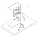
- FIG. 1 is a diagram showing an overall configuration of a charging control system according to the present invention.
- the charging control system 1 includes an electronic settlement device 10, a communication device 20, a communication device 30, a user device 40, and a charging control device 50.
- an electronic settlement device 10 a case where RedTacton (registered trademark) communication technology is used for electronic payment is taken as an example, but various communication technologies can be used.
- RedTacton (registered trademark) communication technology is used for electronic payment is taken as an example, but various communication technologies can be used.
- the electronic payment apparatus 10 and the communication apparatus 20 are stored in a case of a vending machine and a user purchases a product with the vending machine using electronic payment will be described as an example.
- the electronic settlement apparatus 10 is a general computer.
- the electronic payment apparatus 10 is a personal computer, a server computer, or the like.
- the electronic settlement apparatus 10 is connected to the communication apparatus 20 so that data can be transmitted and received.
- the electronic payment apparatus 10 includes a control unit, a storage unit, and a communication unit.
- the control unit includes, for example, one or a plurality of microprocessors.
- the control unit executes processing according to programs and data stored in the storage unit.
- the storage unit includes a main storage unit and an auxiliary storage unit.
- the main storage unit is a RAM
- the auxiliary storage unit is a hard disk or a solid state drive.
- the communication unit is a communication interface such as a network card.
- the communication device 20 is a device that communicates with the communication device 30, and here is an electric field detection sensor.
- the communication device 20 detects an electric field optically, electrically, or magnetically.
- the communication device 20 includes an electrode, a light emitting circuit, a light receiving circuit, and an electro-optic crystal.
- the electrode is exposed from the vending machine and can be touched from the outside.
- the light emitting circuit is a circuit that emits laser light, and includes, for example, a laser diode and a power source.
- the light receiving circuit is a circuit that detects laser light and converts it into an electrical signal, and includes, for example, a photodiode and an A / D converter.
- An electro-optic crystal is a material whose refractive index changes when an electric field is applied, and is, for example, a ferroelectric (oxide crystal) such as lithium niobate.
- the electro-optic crystal is disposed between the light emitting circuit and the light receiving circuit, and the light receiving circuit detects the electric field by detecting the change in the laser light and identifying the change in the refractive index.
- the communication device 20 may include a processor that performs authentication processing with the communication device 30, a memory that stores authentication information, and the like.
- the communication device 30 is a device that communicates with the communication device 20, and here is an electric field generator that generates an electric field.
- the communication device 30 is attached to the user.
- the communication device 30 includes an insulator in contact with a user, an electrode placed on the insulator, a power supply, a power supply control circuit, and a communication unit.
- the communication unit is a communication interface for communicating with the user device 40.
- the power supply control circuit is an integrated circuit including a microprocessor and a memory. Authentication information may be stored in the memory of the power control circuit, and authentication processing with the communication device 20 may be performed by a processor of the power control circuit.
- the power supply control circuit controls the output of the power supply and applies a voltage corresponding to the information received by the communication unit to the electrodes. When the power supply control circuit applies a voltage to the electrodes, an electric field corresponding to the voltage is induced on the surface of the user.
- the user device 40 is a computer operated by a user.
- the user device 40 is a mobile phone (including a smartphone), a portable information terminal (including a tablet computer), a personal computer, or the like.
- the user device 40 includes a control unit, a storage unit, and a communication unit. Since these hardware configurations are the same as those of the control unit, the storage unit, and the communication unit of the electronic settlement apparatus 10, description thereof will be omitted.
- the user device 40 may include an operation unit such as a pointing device and a display unit such as a liquid crystal panel.
- the charging control device 50 is a static electricity generating device that can be attached to the user.
- the charging control device 50 is attached to the user.
- the mounting here means to include both direct mounting and indirect mounting.
- the charging control device 50 is stored inside a user's wearing item (for example, inside a shoe sole of the footwear) and is attached indirectly.
- the footwear may be shoes worn by a person, shoes, sandals or slippers.
- FIG. 2 is a diagram illustrating a state in which the charging control device 50 is stored inside the footwear.
- a charge control device 50, a first electrode 60, and a second electrode 70 are stored inside the footwear.
- the first electrode 60 is provided on the surface in contact with the ground (the back surface of the footwear).
- the first electrode 60 is exposed and comes into contact with the ground when the user wears footwear.
- the 2nd electrode 70 is provided in the surface (inner surface of shoes) which contacts a user.
- the second electrode 70 is exposed and is in direct or indirect contact with the user when the user wears footwear.
- the user's wearing items for example, socks or tights made of conductive material
- the second electrode 70 are in direct contact with the second electrode 70 is in indirect contact with the user.
- the charging control device 50 is connected between the first electrode 60 and the second electrode 70.
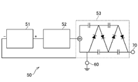
- FIG. 3 is a diagram showing a physical configuration of the charging control device 50.
- the charging control device 50 includes a power supply 51, a microcomputer 52, and a voltage amplification circuit 53.
- the power source 51 may be a battery that can output a constant voltage, and may be an AC power source or a DC power source.
- the charging control device 50 may include an AC-DC conversion circuit.
- the plus terminal of the power supply 51 is connected to the microcomputer 52, and the minus terminal of the power supply 51 is connected to the ground side of the voltage amplification circuit 53.
- the microcomputer 52 is a small computer and includes a control unit, a storage unit, and a communication unit. Since these hardware configurations are the same as those of the control unit, the storage unit, and the communication unit of the electronic settlement apparatus 10, description thereof will be omitted. As shown in FIG. 3, the microcomputer 52 is connected between a power supply 51 and a voltage amplification circuit 53. The microcomputer 52 serves as a switch for connecting or disconnecting the plus terminal of the power source 51 and the voltage amplification circuit 53. Further, the microcomputer 52 may be connected to the electronic settlement apparatus 10, the communication apparatus 20, the communication apparatus 30, or the user apparatus 40 so that data can be transmitted and received.
- the voltage amplification circuit 53 is an electric circuit for obtaining an output voltage larger than the input voltage.
- the voltage amplification circuit 53 is connected between the first electrode 60 and the second electrode 70 and includes a DC input, a capacitor, and a diode.
- the Cockloft-Walton circuit is taken as an example, but the voltage amplification circuit 53 may be any circuit that can amplify the voltage, and various known circuits can be applied. If the power supply 51 can output a sufficient voltage, the voltage amplification circuit 53 may be omitted.
- the sufficient voltage here is a voltage capable of realizing tactile feedback by electrostatic stimulation (that is, a voltage capable of discharging due to dielectric breakdown), for example, a voltage of about several kV to several tens of kV.
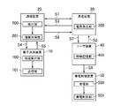
- FIG. 4 is a functional block diagram realized by the charging control system 1.
- the flow of processing executed in the charging control system 1 will be described.
- the following processing is executed when each device constituting the charging control system 1 executes a program, and each function shown in FIG. 4 is realized.
- communication between the electronic payment apparatus 10 and the communication apparatus 20, communication between the communication apparatus 30 and the user apparatus 40, and communication between the user apparatus 40 and the charging control apparatus 50 are established.
- data can be transmitted and received between each other.
- Each communication may be performed in a wired manner or wirelessly.
- the communication device 30 acquires later-described balance information from the user device 40 (S2), and transmits it to the communication device 20 (S3).
- the electronic payment apparatus 10 acquires balance information via the communication apparatus 20 (S4), executes electronic payment processing, and transmits a completion notification to the communication apparatus 20 (S5).
- the communication device 30 transmits it to the user device 40 (S7).
- the charging control device 50 receives a completion notification via the user device 40 (S8).
- the charging control device 50 When the charging control device 50 receives the completion notification in S8, it charges the user. When the user is charged and reaches a predetermined potential, dielectric breakdown occurs in the air between the user's finger and the communication device 20, and the user feels an electrostatic stimulus from the fingertip. As described above, the charging control system 1 is configured such that the user can recognize that the electronic payment is completed by tactile feedback.
- the process execution unit 100, the detection unit 200, the electric field generation unit 300, the information storage unit 400, the reception unit 500, and the charge control unit 501 are respectively a process execution unit, a detection unit, It corresponds to an electric field generating unit, an information storage unit, a receiving unit, and a charging control unit.
- the detection unit 200 is realized mainly by the light receiving circuit and the electro-optic crystal of the communication device 20.
- the detection unit 200 detects a user's contact or proximity to a predetermined object.
- the contact means that the user directly or indirectly contacts a predetermined object. Touching a predetermined part of a user's part (for example, a hand) corresponds to direct contact. Touching a predetermined object with a user's wearing object (for example, a glove worn on the hand) or a gripping object (for example, a metal rod held in the hand) corresponds to indirect contact.
- the proximity means that the user approaches directly or indirectly. That the distance between the user's part (for example, a hand) and a predetermined object is within a predetermined distance corresponds to direct proximity.
- the fact that the distance between a user's wearing object (for example, a glove worn on the hand) or a grasping object (for example, a metal rod held in the hand) and a predetermined object is within a predetermined distance is equivalent to being in close proximity.
- the predetermined distance is a distance that can be detected by the detection unit 200, and may be determined by the performance of the communication device 20 or the communication device 30.
- the predetermined distance may be a distance at which dielectric breakdown is possible with a voltage that can be output by the charging control device 50. In this case, the predetermined distance may be determined by the dielectric constant of an insulator (for example, air) between the user and the predetermined object.
- the predetermined object detected by the detection unit 200 is an object that the user should contact or approach, and may be a predetermined object. In the present embodiment, a case where the communication device 20 corresponds to a predetermined object will be described.
- the detection unit 200 may detect a user's contact or proximity electrically, magnetically, or optically.
- the detection unit 200 may detect the contact or proximity of the user by determining whether or not the strength of the detected electric field is equal to or greater than a threshold, or the communication device 20 and the communication device 30.
- the user's contact or proximity may be detected by determining whether or not communication with the user has been established.
- the electric field generation unit 300 is realized mainly by the power supply control unit of the communication device 30.
- the electric field generator 300 generates an electric field on the surface of the user.
- the electric field generator 300 generates an electric field by applying a voltage to the electrodes of the communication device 30.
- the electric field generator 300 controls the strength of the electric field by controlling the voltage level.
- the electric field generator 300 controls the electric field according to the information to be transmitted.
- the electric field generation unit 300 acquires balance information described later from the user device 40, the electric field generation unit 300 controls the electric field so as to change the numerical value of the balance information. For example, “0” constituting the digital data is expressed by an electric field having a first strength, and “1” is expressed by an electric field having a second strength stronger than the first strength.
- the authentication process of S1 is executed.
- the authentication process may be performed by a method defined by a predetermined communication protocol.
- an authentication process defined by RedTacton registered trademark
- the communication device 20 acquires authentication information stored in the communication device 30 by using an electric field, and executes authentication processing by comparing it with authentication information stored in itself.
- the information storage unit 400 is realized mainly by the storage unit of the user device 40.
- the information storage unit 400 stores information about the user.
- the information storage unit 400 stores balance information indicating the electronic money held by the user.
- the balance information is a numerical value indicating the balance of electronic money.
- the information storage unit 400 may store information other than the balance information.
- the information storage unit 400 may store a user ID for identifying a user and individual identification information of the user device 40, or may store authentication information necessary for electronic payment.
- the balance information stored in the information storage unit 400 is acquired by the communication device 30 and transmitted to the communication device 20.
- the information acquisition unit 201 is realized mainly by the light receiving circuit of the communication device 20.
- the information acquisition unit 201 acquires balance information stored in the information storage unit 400 owned by the user. That the user possesses the information storage unit 400 means that the user possesses (for example, grips or wears) the casing in which the information storage unit 400 is stored.
- the information acquisition unit 201 does not acquire the balance information when the detection unit 200 does not detect user contact or proximity or when an authentication error occurs in the authentication process of S1. In other words, the information acquisition unit 201 acquires the balance information in response to the detection by the detection unit 200 and the completion of the authentication process of S1.
- the information acquisition unit 201 acquires balance information via the transmission path.
- the transmission path may be wired or wireless.
- an electric field an example of wireless
- the information acquisition unit 201 uses the electric field generated on the surface of the user by the electric field generation unit 300 and is stored in the information storage unit 400.
- Balance information is acquired.
- the communication device 30 acquires the balance information stored in the information storage unit 400 of the user device 40 in S2
- the electric field generation unit 300 of the communication device 30 applies an electric field so as to indicate the numerical value of the balance information in S3.
- the information acquisition unit 201 specifies the content of the balance information based on the change in the electric field.
- the process execution unit 100 is realized mainly by the control unit of the electronic settlement apparatus 10.
- the process execution unit 100 executes a predetermined process when the detection unit 200 detects contact or proximity of the user.
- the process execution part 100 performs a predetermined process based on the information acquired using an electric field when the detection part 200 detects a user's contact or proximity.
- the information acquisition unit 201 transmits balance information to the electronic settlement apparatus 10, and the process execution unit 100 acquires balance information.
- the process execution unit 100 executes a predetermined process based on the balance information acquired by the information acquisition unit 201.
- the predetermined process is an electronic payment process executed based on balance information
- Various known processes can be applied to the electronic payment process itself.
- the process execution unit 100 compares the balance information stored in the storage unit of the electronic payment apparatus 10 with the balance information acquired via the information acquisition unit 201.
- the process execution unit 100 changes the balance information by permitting electronic payment if they match, and does not allow electronic payment if they do not match.
- the predetermined process executed by the process execution unit 100 may be a process executed based on the information acquired by the information acquisition unit 201, and is not limited to the electronic payment process.
- the process execution unit 100 may execute a process according to a scene where the charging control system 1 is used.
- the charging control system 1 is used for managing security of entering and exiting a building
- the user authentication process may correspond to a predetermined process.
- the transmission unit 101 is realized mainly by the control unit and the communication unit of the electronic payment apparatus 10.
- the transmission unit 101 transmits a completion notification indicating that the electronic payment process has been completed by the process execution unit 100.
- the completion notification may be information in a predetermined format, and is, for example, a predetermined symbol string (for example, a character string or a numeric string).
- the completion notification can be said to indicate that the electronic payment process executed based on the balance information acquired using the electric field has been completed.
- the transmission unit 101 transmits a completion notification to the charging control device 50 via the transmission path.
- This transmission path and the transmission path for the information acquisition unit 201 to acquire balance information may be the same or different. In this embodiment, a case where these transmission paths are different will be described.
- the transmission unit 101 may transmit information other than the completion notification. For example, the transmission unit 101 may transmit information for updating the balance information. This information is updated balance information or information indicating the amount of change in balance information.
- the transmission unit 101 transmits a completion notification to the communication device 20.
- the completion notification is transferred from the communication device 20 to the communication device 30 in S6, and is transferred from the communication device 30 to the user device 40 in S7.
- the transmission unit 101 transmits information for updating balance information together with the completion notification
- the user device 40 receives the information via the communication device 20 and the communication device 30 and stores the information.
- the balance information of the unit 400 is updated.
- the receiving unit 500 is realized mainly by the microcomputer 52 of the charging control device 50.
- the receiving unit 500 receives a completion notification indicating that the electronic payment process has been completed by the process execution unit 100.
- the receiving unit 500 may directly receive a completion notification from the electronic settlement apparatus 10.
- the receiving unit 500 may directly receive a completion notification from the communication apparatus 20 or the communication apparatus 30. Good.
- the charging controller 501 is realized mainly by the microcomputer 52 of the charging controller 50.
- the charging control unit 501 supplies electricity from the power source to the user and charges it.
- the charging control unit 501 does not supply electricity from the power source to the user when the detection unit 200 does not detect the contact or proximity of the user with the communication device 20.
- the charge control unit 501 may be charged by supplying electricity from the power source to the user in accordance with detection by the detection unit 200. That is, the charging control unit 501 may electrically connect or disconnect the power source and the electrode according to detection by the detection unit 200.
- the charging control unit 501 receives the completion notification by the reception unit 500. Accordingly, the user is charged. That is, the charging control unit 501 does not charge the user when the receiving unit 500 does not receive the completion notification, and charges the user when the receiving unit 500 receives the completion notification.
- the charging controller 501 charges the user to a predetermined potential, dielectric breakdown occurs between the user and the communication device 20, and the user recognizes the completion of electronic payment by tactile feedback.
- the tactile feedback is not unilaterally given from the vending machine, but the user controls the tactile feedback by attaching the charging control device 50 to the user. It is possible to provide tactile feedback in response. For example, since a user who does not need tactile feedback does not have to wear the charging control device 50, it is possible to avoid giving a stimulus to a user who does not need tactile feedback. Further, since the way of feeling the stimulus in the tactile feedback varies depending on the user, the output of the charging control device 50 can be adjusted so as to obtain a desired stimulus.
- the user since the user is charged in response to the reception of the completion notification, the user can recognize that the electronic payment is completed by tactile feedback. Furthermore, since it is a condition for executing electronic payment that the user touches or approaches the communication device 20, tactile feedback can be obtained using a hand that is close to the communication device 20 in order to make an electronic payment, The user can more intuitively understand that the electronic payment has been completed.
- balance information can be transmitted and received more easily. Furthermore, since the user needs to contact or approach the communication device 20 in order to transmit and receive balance information, it is possible to obtain tactile feedback using a hand close to the communication device 20 in order to establish communication. The user can more intuitively understand that the electronic payment has been completed.
- RedTacton registered trademark
- the predetermined process electronic payment processing, for example, a visually impaired person can easily recognize completion of electronic payment.
- the first electrode 60 is disposed on the bottom surface of the footwear, the grounding can be more reliably performed. Furthermore, since the second electrode 70 is disposed on the inner surface of the footwear, the user can be charged more reliably.
- the method of detecting the contact or proximity of the user by the detection unit 200 is not limited to a method using an electric field.
- the detection unit 200 may detect a user's contact or proximity electrically, magnetically, or optically, and may use the following detection method.
- FIG. 5 is a diagram illustrating an overall configuration of the charging control system 1 according to a modification.
- the charge control system 1 according to the modification includes a charge control device 50, a reading device 80, and an IC card 90.
- the charging control device 50 may be the same as that of the embodiment, but here, it is assumed to include a microphone for detecting sound.
- the reading device 80 is a general RFID reader / writer, and includes a control unit, a storage unit, a reading unit, and a speaker.
- the control unit and the storage unit are the same as those described in the embodiment, and the reading unit is a communication circuit for performing wireless communication using an electromagnetic field or a radio tower.
- the speaker may be anything that can output sound.
- the reading device 80 corresponds to a predetermined object according to the present invention.
- the IC card 90 is a general tag and stores ID information and balance information.
- the reading device 80 performs electronic payment by reading the tag of the IC card 90 using wireless communication.
- a method of detecting contact or proximity of the IC card 90 using RFID or a method of performing electronic payment itself a known general method may be applied.
- the case where the IC card 90 is used will be described, but the tag may be stored in the user device 40.
- FIG. 6 is a functional block diagram in the modified example.
- the reading device 80 generates electromagnetic waves and radio waves to the IC card 90 (S10), reads the balance information stored in the IC card (S11), and completes the electronic payment process.
- a predetermined voice indicating the notification is output from the speaker (S12).
- the charging control device 50 detects the sound, specifies that the electronic payment processing is completed, and charges the user.
- the detection unit 200 and the information acquisition unit 201 are realized mainly by the reading unit of the reading device 80.
- the detection unit 200 detects the contact or proximity of the user by detecting the IC card 90 based on electromagnetic waves or radio waves.
- the information acquisition unit 201 acquires the balance information stored in the information storage unit 400 of the IC card 90.
- the process execution unit 100 is realized mainly by the control unit of the reading device 80.
- the function of the process execution unit 100 is the same as that of the embodiment.
- the audio output unit 800 is mainly realized by a speaker of the reading device 80.
- the voice output unit 800 outputs a predetermined voice in S12.
- the audio data stored in the reading device 80 may be output from the speaker.
- a charging control unit 501 In the charging control device 50, a charging control unit 501, a sound detection unit 502, and a sound processing unit 503 are realized.
- the sound detection unit 502 is realized mainly by the microphone of the charging control device 50.
- the sound detection unit 502 detects sound.
- the sound processing unit 503 is realized mainly by the microcomputer 52 of the charging control device 50.
- the voice processing unit 503 analyzes the voice detected by the voice detection unit 502 and determines whether the voice is output when the electronic payment is completed.
- Various known methods can be applied to the method of analyzing speech itself.
- the storage unit of the microcomputer 52 stores the waveform data of the voice that is output when the electronic payment process is completed, and the voice processing unit 503 stores the waveform data and the waveform detected by the voice detection unit 502. , Compare.
- the charging control unit 501 charges the user when it is determined by the sound processing unit 503 that a predetermined sound has been output.
- the method for charging the user itself is the same as the
- the contact or proximity of the user can be detected by using the RFID.
- a predetermined voice is often output when the electronic payment is completed.
- the charging control device 50 according to the modification uses this voice to specify completion of the electronic payment processing.
- the charging control system 1 can be introduced without modifying the existing system. Note that the sound output when the electronic payment process is completed may be output by a computer other than the reading device 80.
- the charging control system 1 may include a camera, and may detect a user's contact or proximity using an image captured by the camera.
- the detection unit 200 is realized mainly with a camera.
- the detection unit 200 analyzes an image captured by the camera and determines whether or not the user has touched or approached a predetermined object.
- the charging control system 1 may include an infrared sensor, and may detect a user's contact or proximity using infrared rays detected by the infrared sensor.
- the detection unit 200 is realized mainly using an infrared sensor.
- the detection unit 200 determines whether or not the user has touched or approached a predetermined object based on the infrared flight time detected by the infrared sensor.
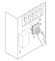
- FIG. 7 is a diagram illustrating an example of the communication device 20 according to the modification. As shown in FIG. 7, a portion where the electrode of the communication device 20 is exposed is covered with an insulator 21.
- the insulator may be a material having a relative dielectric constant within a predetermined value, and may be acrylic or urethane, for example.
- the insulator may be a plate having a predetermined thickness (for example, about 1 mm). In this case, the dielectric breakdown voltage may be a predetermined voltage (for example, about 1 kV).
- FIG. 8 is a cross-sectional view of the insulator 21 taken along the line AA.
- the insulator 21 may have one or more holes.
- the size of the hole is, for example, a size that does not allow a finger to enter (for example, within a diameter of 1 cm).
- the number and size of holes on the surface of the insulator 21 may be arbitrary. Depending on the material of the insulator 21, air may be more likely to be energized. Therefore, the strength of the stimulus felt by the user may be adjusted depending on the number and size of the holes.
- the insulator 21 may cover a user's site
- the insulator 21 is provided between the communication device 20 and the user so that the user does not directly touch the predetermined object (that is, the user touches the predetermined object indirectly through the insulator 21). I just need it.
- the insulator 21 may cover the reading device 80.
- the detection method by the detection unit 200 is the same as the method described in the embodiment and the modification.
- the charging control unit 501 of the present modified example supplies and charges the user with electricity from the power supply 51 when the detection unit 200 detects the user's contact or proximity to the communication device 20 via the insulator 21. It will be.
- the predetermined object is a metal or the like
- the charge may move to the predetermined object and the user may not be sufficiently charged.
- the modified example (2) even if the user contacts a predetermined object, the electric charge can be prevented from escaping from the fingertip, and the user can be charged reliably. As a result, tactile feedback can be given more reliably.
- the configuration of the charging control device 50 is not limited to the example described in the embodiment.
- the charging control device 50 may be configured to charge the user when a predetermined notification is received, and may be a static electricity generating device for charging the human body.
- the charging control device 50 may be a small bandegraph.
- the case where the communication device 30, the user device 40, and the charging control device 50 are separate has been described.
- all or any two of them may be an integrated device.
- tactile feedback can be obtained not only when the electronic payment is completed but also when an error occurs in the electronic payment (for example, insufficient balance, insufficient contact or proximity of the user, or a difference in the type of electronic money used). May be.
- the tactile feedback pattern may be changed depending on whether the electronic payment is normally completed or an error occurs.
- the voltage input to the voltage amplification circuit 53 may be changed under the control of the microcomputer 52 of the charging control device 50.
- the higher the voltage input to the voltage amplification circuit 53 the stronger the stimulus given to the user.
- information indicating a voltage to be output in each pattern is stored in the storage unit of the microcomputer 52 for each tactile feedback pattern, and the microcomputer 52 inputs a voltage to be input to the voltage amplification circuit 53 based on the information.
- a tactile figo back pattern may be defined for each type of processing result of the electronic payment processing (whether it has been completed normally or an error has occurred).
- the microcomputer 52 of the charging control device 50 acquires information indicating the processing result of the electronic payment processing directly or indirectly from the electronic payment device 10, and sends the information to the voltage amplification circuit 53 so that a pattern associated with the information is obtained.
- the input voltage will be controlled.
- the storage unit of each device included in the charging control system 1 may be a flash memory or the like, and the program and data described as being stored in these storage units are stored in an external information storage medium. It may be supplied, or may be supplied from an external computer via a communication unit.
- the devices constituting the charging control system 1 are not limited to the examples of FIGS.
- the charge control system 1 only needs to include at least the charge control device 50.
- the charge control system 1 may be configured only by the charge control device 50 and a computer that detects contact or proximity of the user.
- the charge control system 1 may be applied to a scene where tactile feedback is given to the user, and can be applied to other various scenes.
- the present invention may be applied to a scene where entry / exit to / from a building is managed.
- user authentication information corresponds to information according to the present invention
- user authentication processing corresponds to predetermined processing according to the present invention.
- the communication device 20 and the reading device 80 are arranged at a gate that manages entrance and exit of a building, and authentication is performed when a user holds a hand or an IC card 90 over the communication device 20.
- the charging control device 50 charges the user. Thereby, it can be recognized by tactile feedback that the validity of the user is authenticated.
Landscapes
- Engineering & Computer Science (AREA)
- General Engineering & Computer Science (AREA)
- Theoretical Computer Science (AREA)
- Human Computer Interaction (AREA)
- Physics & Mathematics (AREA)
- General Physics & Mathematics (AREA)
- User Interface Of Digital Computer (AREA)
- Charge And Discharge Circuits For Batteries Or The Like (AREA)
Abstract
ユーザに応じた触覚フィードバックを与えること。帯電制御装置(50)は、ユーザに装着され、電源(51)と、所定の物体に対するユーザの接触又は近接を検出する検出手段(200)によりユーザの接触又は近接が検出された場合に、電源(51)からの電気をユーザに供給して帯電させる帯電制御手段(501)と、を含む。
Description
本発明は、帯電制御装置、帯電制御システム、履物、及び帯電制御方法に関する。
従来、ユーザの皮膚を介して得られる刺激を利用した触覚フィードバックに関する技術が知られている。例えば、特許文献1には、ユーザが操作パネル上で数字を描いて行き先の階を指示するエレベータにおいて、ユーザが適切な数値を入力しているときは、触知タッチパネルから刺激を与え、ユーザが適切な数値を入力していないときは、触知タッチパネルから刺激を与えないようにする技術が記載されている。
上記のような技術では、例えば、触覚フィードバックの必要の有無や刺激の感じ方がユーザによって異なるので、ユーザに応じた触覚フィードバックを与えることが求められている。しかしながら、特許文献1の技術では、エレベータに備えられた触知タッチパネルが一方的に刺激を与えるので、ユーザ個別の対応をすることができず、ユーザに応じた触覚フィードバックを与えることができなかった。
本発明は上記課題に鑑みてなされたものであって、その目的は、ユーザに応じた触覚フィードバックを与えることが可能な帯電制御装置、帯電制御システム、履物、及び帯電制御方法を提供することである。
上記課題を解決するために、本発明に係る帯電制御装置は、ユーザに装着される帯電制御装置であって、電源と、所定の物体に対する前記ユーザの接触又は近接を検出する検出手段により前記ユーザの接触又は近接が検出された場合に、前記電源からの電気を前記ユーザに供給して帯電させる帯電制御手段と、を含むことを特徴とする。
本発明に係る帯電制御システムは、所定の物体に対するユーザの接触又は近接を検出する検出手段と、前記ユーザに装着される帯電制御装置であって、電源と、前記検出手段により前記ユーザの接触又は近接が検出された場合に、前記電源からの電気を前記ユーザに供給して帯電させる帯電制御手段と、を含む帯電制御装置と、を含むことを特徴とする。
本発明に係る履物は、ユーザに装着される履物であって、地面に接する面に配置された第1の電極と、前記ユーザに接する面に備えられた第2の電極と、前記第1の電極と前記第2の電極との間に接続された上記又は下記に記載の帯電制御装置と、を含むことを特徴とする。
本発明に係る帯電制御方法は、ユーザに装着される帯電制御装置により、検出手段により所定の物体に対する前記ユーザの接触又は近接が検出された場合に、電源からの電気を前記ユーザに供給して帯電させることを特徴とする。
また、本発明の一態様によれば、前記帯電制御装置は、前記検出手段により前記ユーザの接触又は近接が検出された場合に所定の処理を実行する処理実行手段により、前記所定の処理が完了したことを示す通知を受信する受信手段を更に含み、前記帯電制御手段は、前記受信手段による前記通知の受信に応じて、前記ユーザを帯電させる、ことを特徴とする。
また、本発明の一態様によれば、前記検出手段は、前記ユーザの表面に電界を発生させる電界発生手段により発生した前記電界に基づいて、前記ユーザの接触又は近接を検出し、前記処理実行手段は、前記ユーザが保有する情報記憶手段に記憶された情報であって、前記検出手段により前記ユーザの接触又は近接が検出された場合に前記電界を利用して取得される前記情報に基づいて、前記所定の処理を実行し、前記受信手段は、前記電界を利用して取得された前記情報に基づいて実行される前記所定の処理が完了したことを示す前記通知を受信する、ことを特徴とする。
また、本発明の一態様によれば、前記情報は、前記ユーザが保有する電子マネーを示し、前記所定の処理は、前記情報に基づいて実行される電子決済処理である、ことを特徴とする。
また、本発明の一態様によれば、前記所定の物体又は前記ユーザの表面の少なくとも一部は、絶縁体に覆われており、前記帯電制御手段は、前記検出手段により、前記絶縁体を介して前記所定の物体に対する前記ユーザの接触又は近接が検出された場合に、前記電源からの電気を前記ユーザに供給して帯電させる、ことを特徴とする。
本発明によれば、ユーザに応じた触覚フィードバックを与えることが可能になる。
[1.帯電制御システムの全体構成]
以下、本発明の実施形態の例について図面に基づき詳細に説明する。本実施形態では、本発明に係る帯電制御システムを電子決済サービスに利用し、ユーザが触覚フィードバックによって電子決済の完了を認知する場面を例に挙げて説明する。
以下、本発明の実施形態の例について図面に基づき詳細に説明する。本実施形態では、本発明に係る帯電制御システムを電子決済サービスに利用し、ユーザが触覚フィードバックによって電子決済の完了を認知する場面を例に挙げて説明する。
図1は、本発明に係る帯電制御システムの全体構成を示す図である。図1に示すように、帯電制御システム1は、電子決済装置10、通信装置20、通信装置30、ユーザ装置40、及び帯電制御装置50を含む。なお、ここでは、電子決済をするために、RedTacton(登録商標)の通信技術を利用する場合を例に挙げるが、種々の通信技術を利用可能である。また、電子決済装置10及び通信装置20が自動販売機の筐体に格納されており、ユーザが電子決済を利用して自動販売機で商品を購入する場面を例に挙げる。
電子決済装置10は、一般的なコンピュータである。例えば、電子決済装置10は、パーソナルコンピュータやサーバコンピュータ等である。電子決済装置10は、通信装置20とデータ送受信可能に接続されている。電子決済装置10は、制御部、記憶部、及び通信部を含む。制御部は、例えば、一又は複数のマイクロプロセッサを含む。制御部は、記憶部に記憶されたプログラムやデータに従って処理を実行する。記憶部は、主記憶部及び補助記憶部を含む。例えば、主記憶部はRAMであり、補助記憶部は、ハードディスク又はソリッドステートドライブ等である。通信部は、ネットワークカード等の通信インタフェースである。
通信装置20は、通信装置30と通信を行う機器であり、ここでは、電界検出センサである。通信装置20は、光学的、電気的、又は磁気的に電界を検出する。例えば、通信装置20は、電極、発光回路、受光回路、及び電気光学結晶を含む。電極は、自動販売機から露出しており、外部から触れることが可能になっている。発光回路は、レーザ光を発する回路であり、例えば、レーザダイオードや電源を含む。受光回路は、レーザ光を検出して電気信号に変換する回路であり、例えば、フォトダイオードやA/D変換器を含む。電気光学結晶は、電界が印加されると屈折率が変化する材料であり、例えば、ニオブ酸リチウム等の強誘電体(酸化物結晶)である。電気光学結晶は、発光回路と受光回路との間に配置され、受光回路は、レーザ光の変化を検出して屈折率の変化を特定することによって、電界を検出する。なお、通信装置20は、通信装置30との間の認証処理を行うプロセッサや認証情報を記憶するメモリ等を含んでいてもよい。
通信装置30は、通信装置20と通信を行う機器であり、ここでは、電界を発生させる電界発生器である。図1では、通信装置30は、ユーザに装着されている。通信装置30は、ユーザに接する絶縁体、絶縁体上に載置された電極、電源、電源制御回路、及び通信部を含む。通信部は、ユーザ装置40と通信するための通信インタフェースである。電源制御回路は、マイクロプロセッサやメモリ等を含む集積回路である。電源制御回路のメモリに認証情報が記憶されており、電源制御回路のプロセッサにより通信装置20との間の認証処理が行われるようにしてもよい。電源制御回路は、電源の出力を制御し、通信部が受信した情報に応じた電圧を電極に印加する。電源制御回路が電極に電圧を印加すると、電圧に応じた電界がユーザの表面に誘起される。
ユーザ装置40は、ユーザが操作するコンピュータである。例えば、ユーザ装置40は、携帯電話機(スマートフォンを含む)、携帯情報端末(タブレット型コンピュータを含む)、又はパーソナルコンピュータ等である。ユーザ装置40は、制御部、記憶部、及び通信部を含む。これらのハードウェア構成は、それぞれ電子決済装置10の制御部、記憶部、及び通信部と同様であるので説明を省略する。なお、ユーザ装置40は、ポインティングデバイス等の操作部や液晶パネル等の表示部を含んでいてもよい。
帯電制御装置50は、ユーザに装着可能な静電気発生装置である。帯電制御装置50は、ユーザに装着される。ここでの装着とは、直接的な装着及び間接的な装着の両方を含む意味である。図1では、帯電制御装置50は、ユーザの装着物の内部(例えば、履物の靴底内部)に格納されており、間接的に装着されている。なお、履物は、人が足に装着するものであればよく、靴であってもよいし、サンダルやスリッパであってもよい。
図2は、帯電制御装置50が履物の内部に格納されている様子を示す図である。図2に示すように、履物の内部には、帯電制御装置50、第1の電極60、及び第2の電極70が格納されている。第1の電極60は、地面に接する面(履物の裏面)に備えられる。第1の電極60は、露出しており、ユーザが履物を履いた場合に地面と接するようになっている。第2の電極70は、ユーザに接する面(靴の内面)に備えられる。第2の電極70は、露出しており、ユーザが履物を履いた場合にユーザと直接的又は間接的に接するようになっている。ここでは、ユーザの装着物(例えば、導電性のある素材の靴下やタイツ)と第2の電極70とが直接的に接することが、第2の電極70がユーザと間接的に接することに相当する。帯電制御装置50は、第1の電極60と第2の電極70との間に接続される。
図3は、帯電制御装置50の物理構成を示す図である。図3に示すように、帯電制御装置50は、電源51、マイコン52、及び電圧増幅回路53を含む。電源51は、一定の電圧を出力可能なバッテリーであればよく、交流電源であってもよいし、直流電源であってもよい。電源51が交流電源である場合には、帯電制御装置50は、交流-直流変換回路を含むようにすればよい。図3に示すように、電源51のプラス端子はマイコン52に接続され、電源51のマイナス端子は電圧増幅回路53のアース側に接続されている。
マイコン52は、小型のコンピュータであり、制御部、記憶部、及び通信部を含む。これらのハードウェア構成は、それぞれ電子決済装置10の制御部、記憶部、及び通信部と同様であるので説明を省略する。図3に示すように、マイコン52は、電源51と電圧増幅回路53との間に接続される。マイコン52は、電源51のプラス端子と電圧増幅回路53とを接続したり切断したりするスイッチの役割を果たす。また、マイコン52は、電子決済装置10、通信装置20、通信装置30、又はユーザ装置40とデータ送受信可能に接続されていてよい。
電圧増幅回路53は、入力電圧よりも大きな出力電圧を得るための電気回路である。電圧増幅回路53は、第1の電極60と第2の電極70との間に接続され、DCインプット、コンデンサ、及びダイオードを含む。図3では、コックロフト・ウォルトン回路を例に挙げるが、電圧増幅回路53は、電圧を増幅可能な回路であればよく、公知の種々の回路を適用可能である。なお、電源51が十分な電圧を出力可能である場合には、電圧増幅回路53は省略してもよい。ここでの十分な電圧とは、静電気的な刺激による触覚フィードバックを実現可能な電圧(即ち、絶縁破壊による放電が可能な電圧)であり、例えば、数kV~数十kV程度の電圧である。
[2.帯電制御システムで実現される機能]
図4は、帯電制御システム1で実現される機能ブロック図である。まず、図4を参照して、帯電制御システム1で実行される処理の流れを説明する。例えば、帯電制御システム1を構成する各装置がプログラムを実行することによって下記の処理が実行されて、図4に示す各機能が実現される。なお、ここでは、電子決済装置10と通信装置20との間の通信、通信装置30とユーザ装置40との間の通信、及びユーザ装置40と帯電制御装置50との間の通信が確立されており、これらの間で互いに互いにデータ送受信可能な状態になっている。各通信は、有線で行われてもよいし、無線で行われてもよい。
図4は、帯電制御システム1で実現される機能ブロック図である。まず、図4を参照して、帯電制御システム1で実行される処理の流れを説明する。例えば、帯電制御システム1を構成する各装置がプログラムを実行することによって下記の処理が実行されて、図4に示す各機能が実現される。なお、ここでは、電子決済装置10と通信装置20との間の通信、通信装置30とユーザ装置40との間の通信、及びユーザ装置40と帯電制御装置50との間の通信が確立されており、これらの間で互いに互いにデータ送受信可能な状態になっている。各通信は、有線で行われてもよいし、無線で行われてもよい。
まず、ユーザの手が通信装置20に近づくと、通信装置20と通信装置30との間で認証処理が行われて通信が確立する(S1)。通信装置30は、ユーザ装置40から後述の残高情報を取得し(S2)、通信装置20に送信する(S3)。電子決済装置10は、通信装置20を介して残高情報を取得し(S4)、電子決済処理を実行して完了通知を通信装置20に送信する(S5)。通信装置30は、通信装置20を介して完了通知を受信すると、ユーザ装置40に送信する(S7)。帯電制御装置50は、ユーザ装置40を介して完了通知を受信する(S8)。
帯電制御装置50は、S8で完了通知を受信すると、ユーザを帯電させることになる。ユーザが帯電して所定の電位に達すると、ユーザの指と通信装置20との間の空気で絶縁破壊が起こり、ユーザは指先から静電気的な刺激を感じる。このように、帯電制御システム1では、触覚フィードバックによって、電子決済が完了したことをユーザが認知することができる構成になっている。
以降、上記処理を実現するための機能の詳細を説明する。なお、本実施形態では、処理実行部100、検出部200、電界発生部300、情報記憶部400、受信部500、及び帯電制御部501は、それぞれ、本発明に係る処理実行手段、検出手段、電界発生手段、情報記憶手段、受信手段、及び帯電制御手段に相当する。
検出部200は、通信装置20の受光回路及び電気光学結晶を主として実現される。検出部200は、所定の物体に対するユーザの接触又は近接を検出する。ここでの接触とは、ユーザが直接的又は間接的に所定の物体に接触することである。ユーザの部位(例えば、手)が所定の物体に触れることが、直接的に接触することに相当する。ユーザの装着物(例えば、手に装着した手袋)又は把持物(例えば、手に持った金属棒)が所定の物体に触れることが、間接的に接触することに相当する。
また、ここでの近接とは、ユーザが直接的又は間接的に近接することである。ユーザの部位(例えば、手)と所定の物体との距離が所定距離以内になることが、直接的に近接することに相当する。ユーザの装着物(例えば、手に装着した手袋)又は把持物(例えば、手に持った金属棒)と所定の物体との距離が所定距離以内になることが、間接的に近接することに相当する。上記所定距離は、検出部200により検出可能な距離であり、通信装置20や通信装置30の性能により定まるようにしてもよい。また、上記所定距離は、帯電制御装置50が出力可能な電圧で絶縁破壊が可能な距離であってもよい。この場合、所定距離は、ユーザと所定の物体との間にある絶縁体(例えば、空気)の誘電率により定まるようにしてもよい。
検出部200が検出する所定の物体は、ユーザが接触又は近接すべき物体であり、予め定められた物体であればよい。本実施形態では、通信装置20が、所定の物体に相当する場合を説明する。検出部200は、電気的、磁気的、又は光学的に、ユーザの接触又は近接を検出するようにすればよい。
本実施形態では、検出部200は、電界発生部300により発生した電界に基づいて、ユーザの接触又は近接を検出する場合を例に挙げて説明する。例えば、検出部200は、検出される電界の強さが閾値以上になったか否かを判定することによって、ユーザの接触又は近接を検出するようにしてもよいし、通信装置20と通信装置30との間の通信が確立したか否かを判定することによって、ユーザの接触又は近接を検出するようにしてもよい。
電界発生部300は、通信装置30の電源制御部を主として実現される。電界発生部300は、ユーザの表面に電界を発生させる。電界発生部300は、通信装置30の電極に電圧を印加することによって、電界を発生させる。電界発生部300は、電圧の高低を制御することによって、電界の強弱を制御する。電界発生部300は、送信対象の情報に応じて電界を制御する。電界発生部300は、ユーザ装置40から後述の残高情報を取得すると、残高情報の数値を示す変化をするように電界を制御する。例えば、デジタルデータを構成する「0」は、第1の強さの電界により表現され、「1」は第1の強さよりも強い第2の強さの電界により表現される。
電界発生部300により発生された電界に基づいて、検出部200によりユーザの接触又は近接が検出されると、S1の認証処理が実行されることになる。認証処理は、所定の通信プロトコルで定められた方式により行われるようにすればよい。ここでは、RedTacton(登録商標)で定められた認証処理が実行される。例えば、通信装置20は、通信装置30に記憶された認証情報を電界を利用して取得し、自身に記憶された認証情報と比較することによって認証処理を実行する。
情報記憶部400は、ユーザ装置40の記憶部を主として実現される。情報記憶部400は、ユーザに関する情報を記憶する。本実施形態では、情報記憶部400は、ユーザが保有する電子マネーを示す残高情報を記憶する。残高情報は、電子マネーの残高を示す数値である。なお、情報記憶部400は、残高情報以外の情報を記憶してもよい。例えば、情報記憶部400は、ユーザを識別するユーザIDやユーザ装置40の個体識別情報を記憶していてもよいし、電子決済に必要な認証情報を記憶していてもよい。情報記憶部400に記憶された残高情報は、通信装置30により取得されて、通信装置20に送信されることになる。
情報取得部201は、通信装置20の受光回路を主として実現される。情報取得部201は、ユーザが保有する情報記憶部400に記憶された残高情報を取得する。ユーザが情報記憶部400を保有するとは、情報記憶部400が格納された筐体をユーザが保有(例えば、把持又は装着)することを意味する。情報取得部201は、検出部200によりユーザの接触又は近接が検出されない場合やS1の認証処理で認証エラーになった場合には、残高情報を取得しない。別の言い方をすれば、情報取得部201は、検出部200による検出やS1の認証処理の完了に応じて、残高情報を取得することになる。
情報取得部201は、伝送路を介して残高情報を取得する。伝送路は、有線であってもよいし、無線であってもよい。本実施形態では、電界(無線の一例)が伝送路として用いられるので、情報取得部201は、電界発生部300によりユーザの表面に発生した電界を利用して、情報記憶部400に記憶された残高情報を取得することになる。例えば、S2において、通信装置30は、ユーザ装置40の情報記憶部400に記憶された残高情報を取得すると、S3において、通信装置30の電界発生部300は残高情報の数値を示すように電界を変化させ、情報取得部201は、この電界の変化に基づいて残高情報の内容を特定することになる。
処理実行部100は、電子決済装置10の制御部を主として実現される。処理実行部100は、検出部200によりユーザの接触又は近接が検出された場合に所定の処理を実行する。本実施形態では、処理実行部100は、検出部200によりユーザの接触又は近接が検出された場合に電界を利用して取得される情報に基づいて、所定の処理を実行する。例えば、S4において、情報取得部201は、残高情報を電子決済装置10に送信し、処理実行部100は、残高情報を取得する。
処理実行部100は、情報取得部201により取得された残高情報に基づいて、所定の処理を実行する。本実施形態では、所定の処理が、残高情報に基づいて実行される電子決済処理である場合を例に挙げて説明する。電子決済処理自体は、公知の種々の処理を適用可能である。例えば、処理実行部100は、電子決済装置10の記憶部に記憶された残高情報と、情報取得部201を介して取得した残高情報と、を比較する。処理実行部100は、これらが一致した場合には、電子決済を許可して残高情報を変化させ、これらが一致していない場合には、電子決済を許可しない。
なお、処理実行部100が実行する所定の処理は、情報取得部201が取得した情報に基づいて実行される処理であればよく、電子決済処理に限られない。処理実行部100は、帯電制御システム1が利用される場面に応じた処理を実行すればよい。例えば、帯電制御システム1が建物への入退出のセキュリティを管理するために利用される場合には、ユーザの認証処理が所定の処理に相当するようにしてもよい。
送信部101は、電子決済装置10の制御部及び通信部を主として実現される。送信部101は、処理実行部100により電子決済処理が完了したことを示す完了通知を送信する。完了通知は、所定形式の情報であればよく、例えば、予め定められた記号列(例えば、文字列や数字列)である。本実施形態では、完了通知は、電界を利用して取得された残高情報に基づいて実行される電子決済処理が完了したことを示すものといえる。
送信部101は、伝送路を介して、帯電制御装置50に対して完了通知を送信する。この伝送路と、情報取得部201が残高情報を取得するための伝送路と、は同じであってもよいし、異なっていてもよい。本実施形態では、これらの伝送路が異なる場合を説明する。なお、送信部101は、完了通知以外の情報を送信してもよい。例えば、送信部101は、残高情報を更新するための情報を送信するようにしてもよい。この情報は、更新後の残高情報、又は、残高情報の変化量を示す情報である。
例えば、S5において、送信部101は、完了通知を通信装置20に送信する。完了通知は、S6において、通信装置20から通信装置30に転送され、S7において、通信装置30からユーザ装置40に転送される。なお、送信部101が完了通知とともに残高情報を更新するための情報を送信していた場合には、ユーザ装置40は、通信装置20及び通信装置30を介して当該情報を受信して、情報記憶部400の残高情報を更新することになる。
受信部500は、帯電制御装置50のマイコン52を主として実現される。受信部500は、処理実行部100により電子決済処理が完了したことを示す完了通知を受信する。受信部500は、伝送路を介して、送信部101により送信された完了通知を受信することになる。例えば、S7において、ユーザ装置40が、通信装置20及び通信装置30を介して完了通知を受信すると帯電制御装置50に転送し、S8において、受信部500は、完了通知を受信することになる。
なお、電子決済装置10と帯電制御装置50とが直接的に接続されている場合には、受信部500は、電子決済装置10から完了通知を直接受信するようにしてもよい。また、電子決済装置10と通信装置20又は通信装置30とが直接的に接続されている場合には、受信部500は、通信装置20や通信装置30から完了通知を直接受信するようにしてもよい。
帯電制御部501は、帯電制御装置50のマイコン52を主として実現される。帯電制御部501は、検出部200により通信装置20に対するユーザの接触又は近接が検出された場合に、電源からの電気をユーザに供給して帯電させる。即ち、帯電制御部501は、検出部200により通信装置20に対するユーザの接触又は近接が検出されない場合には、電源からの電気をユーザに供給しない。別の言い方をすれば、帯電制御部501は、検出部200による検出に応じて、電源からの電気をユーザに供給して帯電させるようにしてもよい。即ち、帯電制御部501は、検出部200による検出に応じて、電源と電極とを電気的に接続したり切断したりするようにしてもよい。
本実施形態では、検出部200によりユーザの接触又は近接が検出された場合に、電子決済処理が実行されて完了通知が送受信されるので、帯電制御部501は、受信部500による完了通知の受信に応じてユーザを帯電させることになる。即ち、帯電制御部501は、受信部500が完了通知を受信しない場合には、ユーザを帯電させず、受信部500が完了通知を受信した場合には、ユーザを帯電させることになる。帯電制御部501によりユーザが帯電して所定の電位になると、ユーザと通信装置20との間で絶縁破壊が発生し、ユーザは、触覚フィードバックにより、電子決済の完了を認知することになる。
[3.実施形態のまとめ]
本実施形態の帯電制御システム1によれば、自動販売機から一方的に触覚フィードバックを与えるのではなく、ユーザに帯電制御装置50を装着させてユーザ側で触覚フィードバックの制御を行うので、ユーザに応じた触覚フィードバックを与えることが可能になる。例えば、触覚フィードバックを必要としないユーザは、帯電制御装置50を身に着けなければよいので、触覚フィードバックを必要としないユーザにも刺激を与えてしまうようなことを回避することができる。また、触覚フィードバックにおける刺激の感じ方はユーザによって異なるので、所望の刺激を得るように帯電制御装置50の出力を調整することもできる。
本実施形態の帯電制御システム1によれば、自動販売機から一方的に触覚フィードバックを与えるのではなく、ユーザに帯電制御装置50を装着させてユーザ側で触覚フィードバックの制御を行うので、ユーザに応じた触覚フィードバックを与えることが可能になる。例えば、触覚フィードバックを必要としないユーザは、帯電制御装置50を身に着けなければよいので、触覚フィードバックを必要としないユーザにも刺激を与えてしまうようなことを回避することができる。また、触覚フィードバックにおける刺激の感じ方はユーザによって異なるので、所望の刺激を得るように帯電制御装置50の出力を調整することもできる。
また、完了通知の受信に応じてユーザを帯電させるので、ユーザは、電子決済が完了したことを触覚フィードバックにより認知することができる。更に、ユーザが通信装置20に接触又は近接することが電子決済を実行するための条件となるので、電子決済をしようとして通信装置20に近づけた手を利用して触覚フィードバックを得ることができ、ユーザは、電子決済が完了したことを、より直観的に把握することができる。
また、RedTacton(登録商標)のように電界を利用して通信をするので、より容易に残高情報の送受信をすることができる。更に、残高情報の送受信をするためには、ユーザが通信装置20に接触又は近接する必要があるので、通信を確立させようとして通信装置20に近づけた手を利用して触覚フィードバックを得ることができ、ユーザは、電子決済が完了したことを、より直観的に把握することができる。
また、所定の処理を電子決済処理とすることで、例えば、視聴覚障害者も電子決済の完了を容易に認知することができる。
また、履物の底面に第1の電極60が配置されているので、より確実にアースを取ることができる。更に、履物の内面に第2の電極70が配置されているので、より確実にユーザを帯電させることができる。
[4.変形例]
なお、本発明は、以上に説明した実施の形態に限定されるものではない。本発明の趣旨を逸脱しない範囲で、適宜変更可能である。
なお、本発明は、以上に説明した実施の形態に限定されるものではない。本発明の趣旨を逸脱しない範囲で、適宜変更可能である。
(1)例えば、検出部200がユーザの接触又は近接を検出する方法は、電界を利用する方法に限られない。検出部200は、電気的、磁気的、又は光学的に、ユーザの接触又は近接を検出するようにすればよく、下記のような検出方法を用いてもよい。
例えば、RFID(Radio Frequency IDentifier)を利用してユーザの接触又は近接を検出してもよい。図5は、変形例における帯電制御システム1の全体構成を示す図である。図5に示すように、変形例の帯電制御システム1は、帯電制御装置50、読取装置80、及びICカード90を含む。帯電制御装置50は、実施形態と同様であってよいが、ここでは、音声を検出するためのマイクを含むものとする。
読取装置80は、一般的なRFIDリーダライタであり、制御部、記憶部、読取部、及びスピーカーを含む。制御部及び記憶部は、実施形態で説明したものと同様であり、読取部は、電磁界や電波塔を用いた無線通信を行うための通信回路である。スピーカーは、音声を出力可能なものであればよい。本変形例では、読取装置80が、本発明に係る所定の物体に相当する。
ICカード90には、一般的なタグであり、ID情報や残高情報が格納されている。読取装置80は、無線通信を利用してICカード90のタグを読み取って電子決済を行う。RFIDを利用してICカード90の接触又は近接を検出する方法や電子決済を行う方法自体は、公知の一般的な方法を適用すればよい。なお、ここでは、ICカード90が用いられる場合を説明するが、タグはユーザ装置40内に格納されているようにしてもよい。
図6は、変形例における機能ブロック図である。まず、実施形態と同様に、帯電制御システム1の処理の概要から説明する。図6に示すように、読取装置80は、ICカード90に対して電磁波や電波を発生し(S10)、ICカードに格納された残高情報を読み取り(S11)、電子決済処理を実行して完了通知を示す所定の音声をスピーカーから出力する(S12)。本変形例では、帯電制御装置50は、この音声を検出することで電子決済処理が完了したことを特定し、ユーザを帯電させることになる。
以降、上記処理を実現するための機能について説明する。帯電制御システム1を構成する各装置がプログラムを実行することによって下記の処理が実行されて、図6に示す各機能が実現される。本変形例では、情報記憶部400は、ICカード90のタグを主として実現される。情報記憶部400の機能は、実施形態と同様である。
検出部200及び情報取得部201は、読取装置80の読取部を主として実現される。S10において、検出部200は、電磁波や電波に基づいてICカード90を検知することによって、ユーザの接触又は近接を検出することになる。S11において、情報取得部201は、ICカード90の情報記憶部400に格納された残高情報を取得することになる。
処理実行部100は、読取装置80の制御部を主として実現される。処理実行部100の機能は、実施形態と同様である。音声出力部800は、読取装置80のスピーカーを主として実現される。処理実行部100により電子決済処理が完了すると、S12において、音声出力部800は、所定の音声を出力する。音声データは、読取装置80に記憶されているものがスピーカーから出力されるようにすればよい。
帯電制御装置50では、帯電制御部501、音声検出部502、及び音声処理部503が実現される。音声検出部502は、帯電制御装置50のマイクを主として実現される。音声検出部502は、音声を検出する。音声処理部503は、帯電制御装置50のマイコン52を主として実現される。音声処理部503は、音声検出部502が検出した音声を解析し、電子決済が完了したときに出力される音声であるか否かを判定する。音声を解析する方法自体は、公知の種々の方法を適用可能である。例えば、マイコン52の記憶部に、電子決済処理が完了したときに出力される音声の波形データを記憶させておき、音声処理部503は、当該波形データと、音声検出部502が検出した波形と、を比較する。帯電制御部501は、音声処理部503により所定の音声が出力されたと判定された場合に、ユーザを帯電させることになる。ユーザを帯電させる方法自体は、実施形態で説明した方法と同様である。
上記変形例によれば、RFIDを利用することで、ユーザの接触又は近接を検出することができる。更に、既存の電子決済のシステムでは、電子決済の完了時に所定の音声を出力することが多いが、変形例の帯電制御装置50は、この音声を利用して電子決済処理の完了を特定するので、既存のシステムに改修を施すことなく、帯電制御システム1を導入することができる。なお、電子決済処理が完了したときに出力される音声は、読取装置80以外のコンピュータにより出力されるようにしてもよい。
また例えば、帯電制御システム1は、カメラを備え、当該カメラで撮影した画像を利用してユーザの接触又は近接を検出してもよい。この場合、検出部200は、カメラを主として実現される。検出部200は、カメラが撮影した画像を解析して、ユーザが所定の物体に接触又は近接したか否かを判定することになる。また例えば、帯電制御システム1は、赤外線センサを備え、当該赤外線センサが検出した赤外線を利用してユーザの接触又は近接を検出してもよい。この場合、検出部200は、赤外線センサを主として実現される。検出部200は、赤外線センサが検出した赤外線の飛行時間をもとに、ユーザが所定の物体に接触又は近接したか否かを判定することになる。
(2)また例えば、実施形態において、通信装置20又はユーザの表面の少なくとも一部が、絶縁体に覆われているようにしてもよい。図7は、変形例における通信装置20の一例を示す図である。図7に示すように、通信装置20の電極が露出している部分が、絶縁体21に覆われている。絶縁体としては、所定値以内の比誘電率を有する材料であればよく、例えば、アクリルやウレタンであってもよい。絶縁体は、所定の厚み(例えば、1mm程度)のプレート状のものであってよい。この場合、絶縁破壊電圧が所定の電圧(例えば、1kV程度)のものであってもよい。
図8は、絶縁体21のA-A線断面図である。図8に示すように、絶縁体21は、一又は複数の穴が開いているようにしいてもよい。この穴の大きさは、例えば、指が入らない程度の大きさ(例えば、直径1cm以内)である。絶縁体21の表面の穴の数及び大きさは任意であってよい。絶縁体21の材料によっては、空気の方が通電しやすい場合もあるので、穴の数や大きさによって、ユーザが感じる刺激の強さを調整してもよい。
なお、上記では、絶縁体21が通信装置20を覆っている場合を説明したが、ユーザの部位(例えば、手や指)を覆っていてもよい。即ち、絶縁体21は、通信装置20側に配置されてもよいし、ユーザ側に配置されていてもよい。絶縁体21は、ユーザが直接的に所定の物体に触れないように(即ち、ユーザが絶縁体21を介して間接的に所定の物体に触れるように)、通信装置20とユーザとの間にあればよい。RFID方式を利用する場合には、絶縁体21が読取装置80を覆っているようにすればよい。
検出部200による検出方法は、実施形態や変形例で説明した方法と同様である。本変形例の帯電制御部501は、検出部200により、絶縁体21を介して通信装置20に対するユーザの接触又は近接が検出された場合に、電源51からの電気をユーザに供給して帯電させることになる。
例えば、所定の物体が金属等であった場合には、ユーザが所定の物体に接触したまま帯電させようとしても、電荷が所定の物体に移動してユーザが十分に帯電しない可能性がある。この点、変形例(2)によれば、ユーザが所定の物体に接触したとしても、電荷が指先から逃げることを防止することができ、ユーザを確実に帯電させることができる。その結果、より確実に触覚フィードバックを与えることができる。
(3)また例えば、帯電制御装置50の構成は、実施形態で説明した例に限られない。帯電制御装置50は、所定の通知を受信した場合にユーザを帯電させるようにすればよく、人体を帯電させるための静電気発生装置であればよい。例えば、帯電制御装置50は、小型のバンデグラフであってもよい。
また例えば、実施形態では、通信装置30、ユーザ装置40、及び帯電制御装置50が別体である場合を説明したが、これらの全部又は何れか2つが一体の装置であってもよい。また、電子決済が完了した場合だけでなく、電子決済でエラー(例えば、残高不足・ユーザの接触又は近接不足・利用する電子マネーの種類の相違)が発生した場合に触覚フィードバックが得られるようにしてもよい。この場合、電子決済が正常に完了した場合と、エラーが発生した場合と、で触覚フィードバックのパターンを変えるようにしてもよい。
なお、触覚フィードバックのパターンを変える方法としては、帯電制御装置50のマイコン52の制御により、電圧増幅回路53に入力する電圧を変化させるようにすればよい。例えば、電圧増幅回路53に入力する電圧が高いほど、ユーザに与える刺激を強くすることができる。例えば、マイコン52の記憶部に、触覚フィードバックのパターンごとに、そのパターンで出力すべき電圧を示す情報が記憶されており、マイコン52は、当該情報に基づいて、電圧増幅回路53に入力する電圧を制御する。この場合、電子決済処理の処理結果の種類ごとに(正常に完了したか、エラーが発生したか等)、触覚フィーゴバックのパターンが定められているようにしてもよい。帯電制御装置50のマイコン52は、電子決済処理の処理結果を示す情報を電子決済装置10から直接的又は間接的に取得し、当該情報に関連付けられたパターンとなるように、電圧増幅回路53に入力する電圧を制御することになる。
また例えば、帯電制御システム1に含まれる各装置の記憶部は、フラッシュメモリ等であってもよく、これらの記憶部に記憶されているものとして説明したプログラムやデータは、外部の情報記憶媒体から供給されるようにしてもよいし、通信部を介して外部のコンピュータから供給されるようにしてもよい。
また例えば、帯電制御システム1を構成する装置は図1や図6の例に限られない。帯電制御システム1は、少なくとも帯電制御装置50を含んでいればよい。例えば、帯電制御装置50と、ユーザの接触又は近接を検出するコンピュータと、のみにより帯電制御システム1が構成されていてもよい。
また例えば、帯電制御システム1が電子決済に用いられる場合を説明したが、帯電制御システム1は、ユーザに触覚フィードバックを与える場面に適用すればよく、他の種々の場面に適用可能である。例えば、先述のように、建物への入退出を管理する場面に適用してもよい。この場合、ユーザの認証情報が本発明に係る情報に相当し、ユーザの認証処理が本発明に係る所定の処理に相当する。例えば、建物の入退出を管理するゲートに通信装置20や読取装置80を配置しておき、ユーザが通信装置20に手やICカード90をかざすと認証が行われる。ユーザの正当性が確認されると帯電制御装置50はユーザを帯電させる。これにより、ユーザの正当性が認証されたことを、触覚フィードバックにより認知することができる。
Claims (8)
- ユーザに装着される帯電制御装置であって、
電源と、
所定の物体に対する前記ユーザの接触又は近接を検出する検出手段により前記ユーザの接触又は近接が検出された場合に、前記電源からの電気を前記ユーザに供給して帯電させる帯電制御手段と、
を含むことを特徴とする帯電制御装置。 - 前記帯電制御装置は、前記検出手段により前記ユーザの接触又は近接が検出された場合に所定の処理を実行する処理実行手段により、前記所定の処理が完了したことを示す通知を受信する受信手段を更に含み、
前記帯電制御手段は、前記受信手段による前記通知の受信に応じて、前記ユーザを帯電させる、
ことを特徴とする請求項1に記載の帯電制御装置。 - 前記検出手段は、前記ユーザの表面に電界を発生させる電界発生手段により発生した前記電界に基づいて、前記ユーザの接触又は近接を検出し、
前記処理実行手段は、前記ユーザが保有する情報記憶手段に記憶された情報であって、前記検出手段により前記ユーザの接触又は近接が検出された場合に前記電界を利用して取得される前記情報に基づいて、前記所定の処理を実行し、
前記受信手段は、前記電界を利用して取得された前記情報に基づいて実行される前記所定の処理が完了したことを示す前記通知を受信する、
ことを特徴とする請求項2に記載の帯電制御装置。 - 前記情報は、前記ユーザが保有する電子マネーを示し、
前記所定の処理は、前記情報に基づいて実行される電子決済処理である、
ことを特徴とする請求項3に記載の帯電制御装置。 - 前記所定の物体又は前記ユーザの表面の少なくとも一部は、絶縁体に覆われており、
前記帯電制御手段は、前記検出手段により、前記絶縁体を介して前記所定の物体に対する前記ユーザの接触又は近接が検出された場合に、前記電源からの電気を前記ユーザに供給して帯電させる、
ことを特徴とする請求項1~4の何れかに記載の帯電制御装置。 - 所定の物体に対するユーザの接触又は近接を検出する検出手段と、
前記ユーザに装着される帯電制御装置であって、電源と、前記検出手段により前記ユーザの接触又は近接が検出された場合に、前記電源からの電気を前記ユーザに供給して帯電させる帯電制御手段と、を含む帯電制御装置と、
を含むことを特徴とする帯電制御システム。 - ユーザに装着される履物であって、
地面に接する面に配置された第1の電極と、
前記ユーザに接する面に備えられた第2の電極と、
前記第1の電極と前記第2の電極との間に接続された請求項1~5の何れかに記載の帯電制御装置と、
を含むことを特徴とする履物。 - ユーザに装着される帯電制御装置により、検出手段により所定の物体に対する前記ユーザの接触又は近接が検出された場合に、電源からの電気を前記ユーザに供給して帯電させることを特徴とする帯電制御方法。
Priority Applications (2)
| Application Number | Priority Date | Filing Date | Title |
|---|---|---|---|
| PCT/JP2015/064199 WO2016185538A1 (ja) | 2015-05-18 | 2015-05-18 | 帯電制御装置、帯電制御システム、履物、及び帯電制御方法 |
| JP2017500095A JP6148424B2 (ja) | 2015-05-18 | 2015-05-18 | 帯電制御装置、帯電制御システム、履物、及び帯電制御方法 |
Applications Claiming Priority (1)
| Application Number | Priority Date | Filing Date | Title |
|---|---|---|---|
| PCT/JP2015/064199 WO2016185538A1 (ja) | 2015-05-18 | 2015-05-18 | 帯電制御装置、帯電制御システム、履物、及び帯電制御方法 |
Publications (1)
| Publication Number | Publication Date |
|---|---|
| WO2016185538A1 true WO2016185538A1 (ja) | 2016-11-24 |
Family
ID=57319658
Family Applications (1)
| Application Number | Title | Priority Date | Filing Date |
|---|---|---|---|
| PCT/JP2015/064199 Ceased WO2016185538A1 (ja) | 2015-05-18 | 2015-05-18 | 帯電制御装置、帯電制御システム、履物、及び帯電制御方法 |
Country Status (2)
| Country | Link |
|---|---|
| JP (1) | JP6148424B2 (ja) |
| WO (1) | WO2016185538A1 (ja) |
Citations (3)
| Publication number | Priority date | Publication date | Assignee | Title |
|---|---|---|---|---|
| JP2011183383A (ja) * | 2010-03-04 | 2011-09-22 | Samsung Electro-Mechanics Co Ltd | 触覚フィードバックデバイス及び電子装置 |
| JP2013056732A (ja) * | 2011-09-07 | 2013-03-28 | Toshiba Elevator Co Ltd | エレベータの操作パネル装置 |
| JP2014052677A (ja) * | 2012-09-05 | 2014-03-20 | Alps Electric Co Ltd | 触覚刺激発生装置および座標入力システム |
-
2015
- 2015-05-18 JP JP2017500095A patent/JP6148424B2/ja active Active
- 2015-05-18 WO PCT/JP2015/064199 patent/WO2016185538A1/ja not_active Ceased
Patent Citations (3)
| Publication number | Priority date | Publication date | Assignee | Title |
|---|---|---|---|---|
| JP2011183383A (ja) * | 2010-03-04 | 2011-09-22 | Samsung Electro-Mechanics Co Ltd | 触覚フィードバックデバイス及び電子装置 |
| JP2013056732A (ja) * | 2011-09-07 | 2013-03-28 | Toshiba Elevator Co Ltd | エレベータの操作パネル装置 |
| JP2014052677A (ja) * | 2012-09-05 | 2014-03-20 | Alps Electric Co Ltd | 触覚刺激発生装置および座標入力システム |
Also Published As
| Publication number | Publication date |
|---|---|
| JPWO2016185538A1 (ja) | 2017-06-08 |
| JP6148424B2 (ja) | 2017-06-14 |
Similar Documents
| Publication | Publication Date | Title |
|---|---|---|
| AU2019213372B2 (en) | Electronic device for controlling communication connection with input device and method of controlling same | |
| KR102229699B1 (ko) | 정보 운용 방법 및 전자 장치 | |
| EP3617866A1 (en) | Electronic device to control screen property based on distance between pen input device and electronic device and method of controlling same | |
| CN105278675A (zh) | 用于被感应的静电触觉效果的系统和方法 | |
| KR102784213B1 (ko) | 단말 및 단말 제어 방법 | |
| US11490223B2 (en) | Method and electronic device for providing notification based on distance of remote input device | |
| EP3814879B1 (en) | ELECTRONIC DEVICE CONTAINING A PENCIL INPUT DEVICE AND METHOD OF USING THE SAME | |
| US11301061B2 (en) | Electronic device identifying gesture with stylus pen and method for operating the same | |
| EP2724222A1 (en) | Mobile touch-generating device and communication with a touchscreen | |
| KR20180078164A (ko) | 착용형 단말기 및 그 동작 방법 | |
| US11574425B2 (en) | Method for providing drawing effects by displaying a drawing output corresponding to a drawing input using a plurality of objects, and electronic device supporting the same | |
| CN107918486A (zh) | 经由可穿戴或手持设备提供静电触觉效果的系统和方法 | |
| US10642385B1 (en) | Touch input device and keyboard device for electronic devices | |
| KR20210016900A (ko) | 스타일러스 펜 및 스타일러스 펜을 인식하는 전자 장치 및 그 동작 방법 | |
| US20200285316A1 (en) | Apparatus for providing haptic pattern on smart device | |
| US10372216B2 (en) | Gesture feedback | |
| JP6148424B2 (ja) | 帯電制御装置、帯電制御システム、履物、及び帯電制御方法 | |
| KR102580884B1 (ko) | 식별한 커버들의 종류에 기반하여 동작을 수행하는 전자 장치 및 그의 동작 방법 | |
| US20190294209A1 (en) | Wearable device, wristwatch, and short distance communication switch method | |
| US11301046B2 (en) | Electronic apparatus, information processing device, and information processing method | |
| KR20160090602A (ko) | 터치 펜 | |
| JP2014157406A (ja) | 近接検知システム、携帯機器、及び制御プログラム | |
| KR20230090104A (ko) | 생체 인증 장치 및 방법 | |
| KR102217356B1 (ko) | 매입식 터치유닛 | |
| KR20150026384A (ko) | 근접 무선 통신 터치 장치 |
Legal Events
| Date | Code | Title | Description |
|---|---|---|---|
| 121 | Ep: the epo has been informed by wipo that ep was designated in this application |
Ref document number: 15892538 Country of ref document: EP Kind code of ref document: A1 |
|
| ENP | Entry into the national phase |
Ref document number: 2017500095 Country of ref document: JP Kind code of ref document: A |
|
| NENP | Non-entry into the national phase |
Ref country code: DE |
|
| 122 | Ep: pct application non-entry in european phase |
Ref document number: 15892538 Country of ref document: EP Kind code of ref document: A1 |