WO2016182067A1 - ゼオライト、該ゼオライトの製造方法、該ゼオライトを使用したハニカム触媒及び排ガス浄化装置 - Google Patents
ゼオライト、該ゼオライトの製造方法、該ゼオライトを使用したハニカム触媒及び排ガス浄化装置 Download PDFInfo
- Publication number
- WO2016182067A1 WO2016182067A1 PCT/JP2016/064328 JP2016064328W WO2016182067A1 WO 2016182067 A1 WO2016182067 A1 WO 2016182067A1 JP 2016064328 W JP2016064328 W JP 2016064328W WO 2016182067 A1 WO2016182067 A1 WO 2016182067A1
- Authority
- WO
- WIPO (PCT)
- Prior art keywords
- zeolite
- honeycomb
- honeycomb catalyst
- honeycomb unit
- present
- Prior art date
- Legal status (The legal status is an assumption and is not a legal conclusion. Google has not performed a legal analysis and makes no representation as to the accuracy of the status listed.)
- Ceased
Links
Images

Classifications
-
- B—PERFORMING OPERATIONS; TRANSPORTING
- B01—PHYSICAL OR CHEMICAL PROCESSES OR APPARATUS IN GENERAL
- B01J—CHEMICAL OR PHYSICAL PROCESSES, e.g. CATALYSIS OR COLLOID CHEMISTRY; THEIR RELEVANT APPARATUS
- B01J29/00—Catalysts comprising molecular sieves
- B01J29/04—Catalysts comprising molecular sieves having base-exchange properties, e.g. crystalline zeolites
- B01J29/06—Crystalline aluminosilicate zeolites; Isomorphous compounds thereof
- B01J29/70—Crystalline aluminosilicate zeolites; Isomorphous compounds thereof of types characterised by their specific structure not provided for in groups B01J29/08 - B01J29/65
- B01J29/72—Crystalline aluminosilicate zeolites; Isomorphous compounds thereof of types characterised by their specific structure not provided for in groups B01J29/08 - B01J29/65 containing iron group metals, noble metals or copper
- B01J29/76—Iron group metals or copper
- B01J29/763—CHA-type, e.g. Chabazite, LZ-218
-
- B—PERFORMING OPERATIONS; TRANSPORTING
- B01—PHYSICAL OR CHEMICAL PROCESSES OR APPARATUS IN GENERAL
- B01D—SEPARATION
- B01D53/00—Separation of gases or vapours; Recovering vapours of volatile solvents from gases; Chemical or biological purification of waste gases, e.g. engine exhaust gases, smoke, fumes, flue gases, aerosols
- B01D53/34—Chemical or biological purification of waste gases
- B01D53/92—Chemical or biological purification of waste gases of engine exhaust gases
- B01D53/94—Chemical or biological purification of waste gases of engine exhaust gases by catalytic processes
-
- B—PERFORMING OPERATIONS; TRANSPORTING
- B01—PHYSICAL OR CHEMICAL PROCESSES OR APPARATUS IN GENERAL
- B01D—SEPARATION
- B01D53/00—Separation of gases or vapours; Recovering vapours of volatile solvents from gases; Chemical or biological purification of waste gases, e.g. engine exhaust gases, smoke, fumes, flue gases, aerosols
- B01D53/34—Chemical or biological purification of waste gases
- B01D53/92—Chemical or biological purification of waste gases of engine exhaust gases
- B01D53/94—Chemical or biological purification of waste gases of engine exhaust gases by catalytic processes
- B01D53/9404—Removing only nitrogen compounds
- B01D53/9409—Nitrogen oxides
- B01D53/9413—Processes characterised by a specific catalyst
- B01D53/9418—Processes characterised by a specific catalyst for removing nitrogen oxides by selective catalytic reduction [SCR] using a reducing agent in a lean exhaust gas
-
- B—PERFORMING OPERATIONS; TRANSPORTING
- B01—PHYSICAL OR CHEMICAL PROCESSES OR APPARATUS IN GENERAL
- B01J—CHEMICAL OR PHYSICAL PROCESSES, e.g. CATALYSIS OR COLLOID CHEMISTRY; THEIR RELEVANT APPARATUS
- B01J29/00—Catalysts comprising molecular sieves
- B01J29/04—Catalysts comprising molecular sieves having base-exchange properties, e.g. crystalline zeolites
- B01J29/06—Crystalline aluminosilicate zeolites; Isomorphous compounds thereof
- B01J29/70—Crystalline aluminosilicate zeolites; Isomorphous compounds thereof of types characterised by their specific structure not provided for in groups B01J29/08 - B01J29/65
- B01J29/72—Crystalline aluminosilicate zeolites; Isomorphous compounds thereof of types characterised by their specific structure not provided for in groups B01J29/08 - B01J29/65 containing iron group metals, noble metals or copper
- B01J29/76—Iron group metals or copper
-
- B—PERFORMING OPERATIONS; TRANSPORTING
- B01—PHYSICAL OR CHEMICAL PROCESSES OR APPARATUS IN GENERAL
- B01J—CHEMICAL OR PHYSICAL PROCESSES, e.g. CATALYSIS OR COLLOID CHEMISTRY; THEIR RELEVANT APPARATUS
- B01J35/00—Catalysts, in general, characterised by their form or physical properties
- B01J35/30—Catalysts, in general, characterised by their form or physical properties characterised by their physical properties
-
- B—PERFORMING OPERATIONS; TRANSPORTING
- B01—PHYSICAL OR CHEMICAL PROCESSES OR APPARATUS IN GENERAL
- B01J—CHEMICAL OR PHYSICAL PROCESSES, e.g. CATALYSIS OR COLLOID CHEMISTRY; THEIR RELEVANT APPARATUS
- B01J35/00—Catalysts, in general, characterised by their form or physical properties
- B01J35/50—Catalysts, in general, characterised by their form or physical properties characterised by their shape or configuration
-
- B—PERFORMING OPERATIONS; TRANSPORTING
- B01—PHYSICAL OR CHEMICAL PROCESSES OR APPARATUS IN GENERAL
- B01J—CHEMICAL OR PHYSICAL PROCESSES, e.g. CATALYSIS OR COLLOID CHEMISTRY; THEIR RELEVANT APPARATUS
- B01J35/00—Catalysts, in general, characterised by their form or physical properties
- B01J35/50—Catalysts, in general, characterised by their form or physical properties characterised by their shape or configuration
- B01J35/56—Foraminous structures having flow-through passages or channels, e.g. grids or three-dimensional [3D] monoliths
-
- B—PERFORMING OPERATIONS; TRANSPORTING
- B01—PHYSICAL OR CHEMICAL PROCESSES OR APPARATUS IN GENERAL
- B01J—CHEMICAL OR PHYSICAL PROCESSES, e.g. CATALYSIS OR COLLOID CHEMISTRY; THEIR RELEVANT APPARATUS
- B01J37/00—Processes, in general, for preparing catalysts; Processes, in general, for activation of catalysts
- B01J37/0009—Use of binding agents; Moulding; Pressing; Powdering; Granulating; Addition of materials ameliorating the mechanical properties of the product catalyst
- B01J37/0018—Addition of a binding agent or of material, later completely removed among others as result of heat treatment, leaching or washing,(e.g. forming of pores; protective layer, desintegrating by heat)
-
- B—PERFORMING OPERATIONS; TRANSPORTING
- B01—PHYSICAL OR CHEMICAL PROCESSES OR APPARATUS IN GENERAL
- B01J—CHEMICAL OR PHYSICAL PROCESSES, e.g. CATALYSIS OR COLLOID CHEMISTRY; THEIR RELEVANT APPARATUS
- B01J37/00—Processes, in general, for preparing catalysts; Processes, in general, for activation of catalysts
- B01J37/30—Ion-exchange
-
- C—CHEMISTRY; METALLURGY
- C01—INORGANIC CHEMISTRY
- C01B—NON-METALLIC ELEMENTS; COMPOUNDS THEREOF; METALLOIDS OR COMPOUNDS THEREOF NOT COVERED BY SUBCLASS C01C
- C01B39/00—Compounds having molecular sieve and base-exchange properties, e.g. crystalline zeolites; Their preparation; After-treatment, e.g. ion-exchange or dealumination
- C01B39/02—Crystalline aluminosilicate zeolites; Isomorphous compounds thereof; Direct preparation thereof; Preparation thereof starting from a reaction mixture containing a crystalline zeolite of another type, or from preformed reactants; After-treatment thereof
- C01B39/06—Preparation of isomorphous zeolites characterised by measures to replace the aluminium or silicon atoms in the lattice framework by atoms of other elements, i.e. by direct or secondary synthesis
-
- C—CHEMISTRY; METALLURGY
- C01—INORGANIC CHEMISTRY
- C01B—NON-METALLIC ELEMENTS; COMPOUNDS THEREOF; METALLOIDS OR COMPOUNDS THEREOF NOT COVERED BY SUBCLASS C01C
- C01B39/00—Compounds having molecular sieve and base-exchange properties, e.g. crystalline zeolites; Their preparation; After-treatment, e.g. ion-exchange or dealumination
- C01B39/02—Crystalline aluminosilicate zeolites; Isomorphous compounds thereof; Direct preparation thereof; Preparation thereof starting from a reaction mixture containing a crystalline zeolite of another type, or from preformed reactants; After-treatment thereof
- C01B39/14—Type A
- C01B39/145—Type A using at least one organic template directing agent
-
- C—CHEMISTRY; METALLURGY
- C01—INORGANIC CHEMISTRY
- C01B—NON-METALLIC ELEMENTS; COMPOUNDS THEREOF; METALLOIDS OR COMPOUNDS THEREOF NOT COVERED BY SUBCLASS C01C
- C01B39/00—Compounds having molecular sieve and base-exchange properties, e.g. crystalline zeolites; Their preparation; After-treatment, e.g. ion-exchange or dealumination
- C01B39/02—Crystalline aluminosilicate zeolites; Isomorphous compounds thereof; Direct preparation thereof; Preparation thereof starting from a reaction mixture containing a crystalline zeolite of another type, or from preformed reactants; After-treatment thereof
- C01B39/46—Other types characterised by their X-ray diffraction pattern and their defined composition
- C01B39/48—Other types characterised by their X-ray diffraction pattern and their defined composition using at least one organic template directing agent
-
- F—MECHANICAL ENGINEERING; LIGHTING; HEATING; WEAPONS; BLASTING
- F01—MACHINES OR ENGINES IN GENERAL; ENGINE PLANTS IN GENERAL; STEAM ENGINES
- F01N—GAS-FLOW SILENCERS OR EXHAUST APPARATUS FOR MACHINES OR ENGINES IN GENERAL; GAS-FLOW SILENCERS OR EXHAUST APPARATUS FOR INTERNAL-COMBUSTION ENGINES
- F01N3/00—Exhaust or silencing apparatus having means for purifying, rendering innocuous, or otherwise treating exhaust
- F01N3/08—Exhaust or silencing apparatus having means for purifying, rendering innocuous, or otherwise treating exhaust for rendering innocuous
- F01N3/10—Exhaust or silencing apparatus having means for purifying, rendering innocuous, or otherwise treating exhaust for rendering innocuous by thermal or catalytic conversion of noxious components of exhaust
-
- F—MECHANICAL ENGINEERING; LIGHTING; HEATING; WEAPONS; BLASTING
- F01—MACHINES OR ENGINES IN GENERAL; ENGINE PLANTS IN GENERAL; STEAM ENGINES
- F01N—GAS-FLOW SILENCERS OR EXHAUST APPARATUS FOR MACHINES OR ENGINES IN GENERAL; GAS-FLOW SILENCERS OR EXHAUST APPARATUS FOR INTERNAL-COMBUSTION ENGINES
- F01N3/00—Exhaust or silencing apparatus having means for purifying, rendering innocuous, or otherwise treating exhaust
- F01N3/08—Exhaust or silencing apparatus having means for purifying, rendering innocuous, or otherwise treating exhaust for rendering innocuous
- F01N3/10—Exhaust or silencing apparatus having means for purifying, rendering innocuous, or otherwise treating exhaust for rendering innocuous by thermal or catalytic conversion of noxious components of exhaust
- F01N3/24—Exhaust or silencing apparatus having means for purifying, rendering innocuous, or otherwise treating exhaust for rendering innocuous by thermal or catalytic conversion of noxious components of exhaust characterised by constructional aspects of converting apparatus
- F01N3/28—Construction of catalytic reactors
- F01N3/2803—Construction of catalytic reactors characterised by structure, by material or by manufacturing of catalyst support
- F01N3/2825—Ceramics
- F01N3/2828—Ceramic multi-channel monoliths, e.g. honeycombs
-
- F—MECHANICAL ENGINEERING; LIGHTING; HEATING; WEAPONS; BLASTING
- F01—MACHINES OR ENGINES IN GENERAL; ENGINE PLANTS IN GENERAL; STEAM ENGINES
- F01N—GAS-FLOW SILENCERS OR EXHAUST APPARATUS FOR MACHINES OR ENGINES IN GENERAL; GAS-FLOW SILENCERS OR EXHAUST APPARATUS FOR INTERNAL-COMBUSTION ENGINES
- F01N3/00—Exhaust or silencing apparatus having means for purifying, rendering innocuous, or otherwise treating exhaust
- F01N3/08—Exhaust or silencing apparatus having means for purifying, rendering innocuous, or otherwise treating exhaust for rendering innocuous
- F01N3/10—Exhaust or silencing apparatus having means for purifying, rendering innocuous, or otherwise treating exhaust for rendering innocuous by thermal or catalytic conversion of noxious components of exhaust
- F01N3/24—Exhaust or silencing apparatus having means for purifying, rendering innocuous, or otherwise treating exhaust for rendering innocuous by thermal or catalytic conversion of noxious components of exhaust characterised by constructional aspects of converting apparatus
- F01N3/28—Construction of catalytic reactors
- F01N3/2839—Arrangements for mounting catalyst support in housing, e.g. with means for compensating thermal expansion or vibration
- F01N3/2853—Arrangements for mounting catalyst support in housing, e.g. with means for compensating thermal expansion or vibration using mats or gaskets between catalyst body and housing
-
- B—PERFORMING OPERATIONS; TRANSPORTING
- B01—PHYSICAL OR CHEMICAL PROCESSES OR APPARATUS IN GENERAL
- B01D—SEPARATION
- B01D2251/00—Reactants
- B01D2251/20—Reductants
- B01D2251/206—Ammonium compounds
- B01D2251/2067—Urea
-
- B—PERFORMING OPERATIONS; TRANSPORTING
- B01—PHYSICAL OR CHEMICAL PROCESSES OR APPARATUS IN GENERAL
- B01D—SEPARATION
- B01D2255/00—Catalysts
- B01D2255/20—Metals or compounds thereof
- B01D2255/206—Rare earth metals
- B01D2255/2065—Cerium
-
- B—PERFORMING OPERATIONS; TRANSPORTING
- B01—PHYSICAL OR CHEMICAL PROCESSES OR APPARATUS IN GENERAL
- B01D—SEPARATION
- B01D2255/00—Catalysts
- B01D2255/20—Metals or compounds thereof
- B01D2255/207—Transition metals
- B01D2255/20761—Copper
-
- B—PERFORMING OPERATIONS; TRANSPORTING
- B01—PHYSICAL OR CHEMICAL PROCESSES OR APPARATUS IN GENERAL
- B01D—SEPARATION
- B01D2255/00—Catalysts
- B01D2255/50—Zeolites
-
- B—PERFORMING OPERATIONS; TRANSPORTING
- B01—PHYSICAL OR CHEMICAL PROCESSES OR APPARATUS IN GENERAL
- B01J—CHEMICAL OR PHYSICAL PROCESSES, e.g. CATALYSIS OR COLLOID CHEMISTRY; THEIR RELEVANT APPARATUS
- B01J2229/00—Aspects of molecular sieve catalysts not covered by B01J29/00
- B01J2229/10—After treatment, characterised by the effect to be obtained
- B01J2229/18—After treatment, characterised by the effect to be obtained to introduce other elements into or onto the molecular sieve itself
- B01J2229/186—After treatment, characterised by the effect to be obtained to introduce other elements into or onto the molecular sieve itself not in framework positions
-
- B—PERFORMING OPERATIONS; TRANSPORTING
- B01—PHYSICAL OR CHEMICAL PROCESSES OR APPARATUS IN GENERAL
- B01J—CHEMICAL OR PHYSICAL PROCESSES, e.g. CATALYSIS OR COLLOID CHEMISTRY; THEIR RELEVANT APPARATUS
- B01J2229/00—Aspects of molecular sieve catalysts not covered by B01J29/00
- B01J2229/30—After treatment, characterised by the means used
- B01J2229/42—Addition of matrix or binder particles
-
- B—PERFORMING OPERATIONS; TRANSPORTING
- B01—PHYSICAL OR CHEMICAL PROCESSES OR APPARATUS IN GENERAL
- B01J—CHEMICAL OR PHYSICAL PROCESSES, e.g. CATALYSIS OR COLLOID CHEMISTRY; THEIR RELEVANT APPARATUS
- B01J2235/00—Indexing scheme associated with group B01J35/00, related to the analysis techniques used to determine the catalysts form or properties
- B01J2235/15—X-ray diffraction
-
- B—PERFORMING OPERATIONS; TRANSPORTING
- B01—PHYSICAL OR CHEMICAL PROCESSES OR APPARATUS IN GENERAL
- B01J—CHEMICAL OR PHYSICAL PROCESSES, e.g. CATALYSIS OR COLLOID CHEMISTRY; THEIR RELEVANT APPARATUS
- B01J35/00—Catalysts, in general, characterised by their form or physical properties
- B01J35/70—Catalysts, in general, characterised by their form or physical properties characterised by their crystalline properties, e.g. semi-crystalline
-
- C—CHEMISTRY; METALLURGY
- C01—INORGANIC CHEMISTRY
- C01P—INDEXING SCHEME RELATING TO STRUCTURAL AND PHYSICAL ASPECTS OF SOLID INORGANIC COMPOUNDS
- C01P2002/00—Crystal-structural characteristics
- C01P2002/70—Crystal-structural characteristics defined by measured X-ray, neutron or electron diffraction data
- C01P2002/74—Crystal-structural characteristics defined by measured X-ray, neutron or electron diffraction data by peak-intensities or a ratio thereof only
-
- C—CHEMISTRY; METALLURGY
- C01—INORGANIC CHEMISTRY
- C01P—INDEXING SCHEME RELATING TO STRUCTURAL AND PHYSICAL ASPECTS OF SOLID INORGANIC COMPOUNDS
- C01P2004/00—Particle morphology
- C01P2004/60—Particles characterised by their size
- C01P2004/62—Submicrometer sized, i.e. from 0.1-1 micrometer
-
- F—MECHANICAL ENGINEERING; LIGHTING; HEATING; WEAPONS; BLASTING
- F01—MACHINES OR ENGINES IN GENERAL; ENGINE PLANTS IN GENERAL; STEAM ENGINES
- F01N—GAS-FLOW SILENCERS OR EXHAUST APPARATUS FOR MACHINES OR ENGINES IN GENERAL; GAS-FLOW SILENCERS OR EXHAUST APPARATUS FOR INTERNAL-COMBUSTION ENGINES
- F01N2330/00—Structure of catalyst support or particle filter
- F01N2330/06—Ceramic, e.g. monoliths
-
- F—MECHANICAL ENGINEERING; LIGHTING; HEATING; WEAPONS; BLASTING
- F01—MACHINES OR ENGINES IN GENERAL; ENGINE PLANTS IN GENERAL; STEAM ENGINES
- F01N—GAS-FLOW SILENCERS OR EXHAUST APPARATUS FOR MACHINES OR ENGINES IN GENERAL; GAS-FLOW SILENCERS OR EXHAUST APPARATUS FOR INTERNAL-COMBUSTION ENGINES
- F01N2370/00—Selection of materials for exhaust purification
- F01N2370/02—Selection of materials for exhaust purification used in catalytic reactors
- F01N2370/04—Zeolitic material
-
- F—MECHANICAL ENGINEERING; LIGHTING; HEATING; WEAPONS; BLASTING
- F01—MACHINES OR ENGINES IN GENERAL; ENGINE PLANTS IN GENERAL; STEAM ENGINES
- F01N—GAS-FLOW SILENCERS OR EXHAUST APPARATUS FOR MACHINES OR ENGINES IN GENERAL; GAS-FLOW SILENCERS OR EXHAUST APPARATUS FOR INTERNAL-COMBUSTION ENGINES
- F01N2510/00—Surface coverings
- F01N2510/06—Surface coverings for exhaust purification, e.g. catalytic reaction
- F01N2510/063—Surface coverings for exhaust purification, e.g. catalytic reaction zeolites
-
- F—MECHANICAL ENGINEERING; LIGHTING; HEATING; WEAPONS; BLASTING
- F01—MACHINES OR ENGINES IN GENERAL; ENGINE PLANTS IN GENERAL; STEAM ENGINES
- F01N—GAS-FLOW SILENCERS OR EXHAUST APPARATUS FOR MACHINES OR ENGINES IN GENERAL; GAS-FLOW SILENCERS OR EXHAUST APPARATUS FOR INTERNAL-COMBUSTION ENGINES
- F01N3/00—Exhaust or silencing apparatus having means for purifying, rendering innocuous, or otherwise treating exhaust
- F01N3/08—Exhaust or silencing apparatus having means for purifying, rendering innocuous, or otherwise treating exhaust for rendering innocuous
- F01N3/10—Exhaust or silencing apparatus having means for purifying, rendering innocuous, or otherwise treating exhaust for rendering innocuous by thermal or catalytic conversion of noxious components of exhaust
- F01N3/18—Exhaust or silencing apparatus having means for purifying, rendering innocuous, or otherwise treating exhaust for rendering innocuous by thermal or catalytic conversion of noxious components of exhaust characterised by methods of operation; Control
- F01N3/20—Exhaust or silencing apparatus having means for purifying, rendering innocuous, or otherwise treating exhaust for rendering innocuous by thermal or catalytic conversion of noxious components of exhaust characterised by methods of operation; Control specially adapted for catalytic conversion
- F01N3/206—Adding periodically or continuously substances to exhaust gases for promoting purification, e.g. catalytic material in liquid form, NOx reducing agents
- F01N3/2066—Selective catalytic reduction [SCR]
-
- F—MECHANICAL ENGINEERING; LIGHTING; HEATING; WEAPONS; BLASTING
- F01—MACHINES OR ENGINES IN GENERAL; ENGINE PLANTS IN GENERAL; STEAM ENGINES
- F01N—GAS-FLOW SILENCERS OR EXHAUST APPARATUS FOR MACHINES OR ENGINES IN GENERAL; GAS-FLOW SILENCERS OR EXHAUST APPARATUS FOR INTERNAL-COMBUSTION ENGINES
- F01N3/00—Exhaust or silencing apparatus having means for purifying, rendering innocuous, or otherwise treating exhaust
- F01N3/08—Exhaust or silencing apparatus having means for purifying, rendering innocuous, or otherwise treating exhaust for rendering innocuous
- F01N3/10—Exhaust or silencing apparatus having means for purifying, rendering innocuous, or otherwise treating exhaust for rendering innocuous by thermal or catalytic conversion of noxious components of exhaust
- F01N3/24—Exhaust or silencing apparatus having means for purifying, rendering innocuous, or otherwise treating exhaust for rendering innocuous by thermal or catalytic conversion of noxious components of exhaust characterised by constructional aspects of converting apparatus
- F01N3/28—Construction of catalytic reactors
- F01N3/2803—Construction of catalytic reactors characterised by structure, by material or by manufacturing of catalyst support
- F01N3/2807—Metal other than sintered metal
- F01N3/281—Metallic honeycomb monoliths made of stacked or rolled sheets, foils or plates
Definitions
- the present invention relates to zeolite, a method for producing the zeolite, a honeycomb catalyst using the zeolite, and an exhaust gas purification device.
- an SCR (Selective Catalytic Reduction) system that uses ammonia to reduce NOx to nitrogen and water has been known as one of the systems for purifying exhaust gas from automobiles, and has a CHA-structured zeolite carrying copper. Has attracted attention as a zeolite having an SCR catalytic action.
- a honeycomb unit having a large number of longitudinally extending through-holes through which exhaust gas passes is used as an SCR catalyst carrier.
- Patent Document 1 discloses that the honeycomb unit is used as an SCR catalyst carrier.
- a zeolite having a CHA structure having a composition ratio SiO 2 / Al 2 O 3 of less than 15 and a particle diameter of 1.0 to 8.0 ⁇ m is disclosed. .
- Patent Document 2 discloses a zeolite having a CHA structure having a composition ratio SiO 2 / Al 2 O 3 of less than 15 and an alkali content of less than 3% by mass.
- the surface of the honeycomb unit substrate made of the above material is coated with the above-described CHA-structured zeolite to obtain an effect as an SCR catalyst.
- Patent Document 3 discloses a technique in which zeolite is extruded into a honeycomb shape together with an inorganic binder or the like and used as an SCR catalyst when manufacturing the above-described honeycomb unit.
- the silica to alumina molar ratio is from about 10 to about 30, and from about 1.5 to about 5 weight percent of exchange non-aluminum transition metals (eg, copper (for example, copper ( Cu)) and a catalyst composition comprising about 1.35 weight percent or more cerium (Ce) is disclosed.
- exchange non-aluminum transition metals eg, copper (for example, copper ( Cu)
- Ce cerium
- Japanese Unexamined Patent Publication No. 2012-211066 Japanese National Table of Contents 2012-508096 Japanese Unexamined Patent Publication No. 2007-296521 Japanese National Table 2015-500138
- the above prior art has the following problems. That is, the CHA-structured zeolite having a particle size of 1.0 to 8.0 ⁇ m described in Patent Document 1 (hereinafter sometimes referred to as CHA-type zeolite) is heat resistant for use as an SCR for purifying automobile exhaust gas. Therefore, there is a problem that the NOx purification rate after the heat load is applied is low.
- the present invention has been made to solve the above problems, and provides a zeolite excellent in NOx purification performance, particularly excellent in NOx purification performance after thermal endurance, a honeycomb catalyst using the zeolite, and an exhaust gas purification device. For the purpose.
- the zeolite of the present invention is a zeolite having a CHA structure in which Cu and Ce are supported, the Cu / Al molar ratio is 0.25 to 0.48, and the Ce / Al molar ratio is 0.01 to It is 0.03.
- the present inventor has improved the heat resistance by setting the Ce / Al molar ratio to 0.01 or more in the zeolite having a CHA structure (the heat-induced zeolite It was found that the oxidation of ammonia as a reducing agent can be suppressed by suppressing structural destruction to 0.03 or less.
- the amount of Cu to be supported can be increased, and by setting it to 0.48 or less, Cu cannot be ion-exchanged and is present as CuO. it can.
- the zeolite of the present invention preferably has a SiO 2 / Al 2 O 3 composition ratio (SAR) of less than 15.
- SAR SiO 2 / Al 2 O 3 composition ratio
- the zeolite of the present invention preferably has an average particle size of 0.5 ⁇ m or less. Since zeolite with an average particle size of 0.5 ⁇ m or less and a small particle size is used, the amount of water absorption displacement is small when a honeycomb catalyst is used, cracks are unlikely to occur during production and use as a catalyst, and excellent durability. Yes. On the other hand, when the average particle diameter exceeds 0.5 ⁇ m, the amount of water absorption displacement when the honeycomb catalyst is made increases, and cracks may occur in the honeycomb catalyst.
- the sum of the integrated intensities of the (211) plane, (104) plane and (220) plane of the X-ray diffraction spectrum by the powder X-ray analysis method for the zeolite having the CHA structure is 55000 or more Is preferred. Higher integrated intensity indicates better crystallinity, and high NOx purification performance can be obtained when the sum of integrated intensity is 55000 or more.
- the zeolite production method of the present invention is synthesized by reacting a raw material composition containing a Si source, an Al source, an alkali source, water and a structure directing agent, and the Al source is preferably a dry aluminum hydroxide gel. . According to the method of the present invention, since the solubility in an alkaline solution is high, it is possible to reduce the variation in the particle diameter of the synthesized zeolite and the SiO 2 / Al 2 O 3 molar ratio.
- the molar ratio of the Si source and the Al source (SiO 2 / Al 2 O 3 ) in the raw material composition is preferably 10 to 15.
- SiO 2 / Al 2 O 3 is in the above range, a zeolite having a SAR of less than 15 can be easily obtained.
- a honeycomb catalyst of the present invention is a honeycomb catalyst including a honeycomb unit in which a plurality of through holes extending in the longitudinal direction are arranged in parallel with a partition wall, the honeycomb unit including a zeolite and an inorganic binder, As described above, the zeolite of the present invention is used.
- honeycomb catalyst of the present invention Since the above-described zeolite of the present invention is used for the honeycomb catalyst of the present invention, a honeycomb catalyst composed of a honeycomb unit having a high NOx purification rate can be obtained.
- the exhaust gas purifying apparatus of the present invention is formed by placing a holding sealing material on the outer peripheral portion of the honeycomb catalyst of the present invention and canning the metal container.
- the exhaust gas purification apparatus of the present invention it is possible to provide an exhaust gas purification apparatus that is excellent in NOx purification performance, in particular, excellent in NOx purification performance after thermal endurance.
- a zeolite excellent in NOx purification performance, particularly excellent in NOx purification performance after thermal durability, a honeycomb catalyst using the zeolite, and an exhaust gas purification device can be provided.
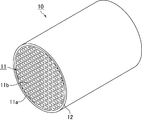
- FIG. 1 is a perspective view schematically showing an example of the honeycomb catalyst of the present invention.
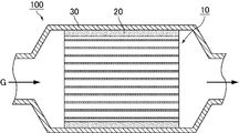
- FIG. 2 is a cross-sectional view schematically showing an example of the exhaust gas purifying apparatus of the present invention.
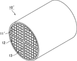
- FIG. 3 is a perspective view schematically showing another example of the honeycomb catalyst of the present invention.
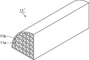
- FIG. 4 is a perspective view schematically showing an example of a honeycomb unit constituting another honeycomb catalyst of the present invention.
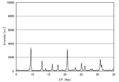
- FIG. 5 is a chart showing an XRD pattern of zeolite (initial) synthesized by “synthesis of zeolite A”.
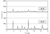
- FIG. 6 is a chart showing an XRD pattern of the zeolite synthesized in Comparative Example 1 (before and after the heat durability test).
- FIG. 7 is a chart showing an XRD pattern of the zeolite synthesized in Example 1 (before the heat durability test and after the heat durability test).
- the zeolite of the present invention is a zeolite having a CHA structure in which Cu and Ce are supported, and has a Cu / Al molar ratio of 0.25 to 0.48 and a Ce / Al molar ratio of 0.01 to 0.00. 03.
- the zeolite of the present invention is a zeolite having a crystal structure equivalent to that of naturally produced chabasite, which is named and classified by the structure code CHA in the International Zeolite Association (IZA). .
- the crystal structure of zeolite can be analyzed using an X-ray diffraction (XRD) apparatus.
- XRD X-ray diffraction
- XRD measurement is performed using an X-ray diffractometer (Uriga IV manufactured by Rigaku Corporation).
- the sample weight should not be changed by 0.1% or more before and after the XRD measurement.
- the obtained XRD data is subjected to peak search using the powder X-ray diffraction pattern comprehensive analysis software JADE 6.0, and the half width and integrated intensity of each peak are calculated.
- the integrated intensity of the peaks of the (211) plane, (104) plane, and (220) plane of zeolite is used is that the influence of water absorption of the sample is small.
- the sum of the integrated strengths is preferably 55000 or more.
- the Ce / Al molar ratio is 0.01 to 0.03.
- the heat resistance is improved (inhibition of structural destruction of the zeolite due to heat)
- the Ce / Al molar ratio is 0.03 or less
- the oxidation of ammonia as a reducing agent can be prevented.
- a more preferable Ce / Al molar ratio is 0.01 to 0.02.
- Another feature of the zeolite of the present invention is that the Cu / Al molar ratio is 0.25 to 0.48.
- the amount of Cu can be increased, and by setting it to 0.48 or less, it is possible to prevent Cu from being ion-exchanged and existing as CuO.
- a more preferable Cu / Al molar ratio is 0.30 to 0.45.
- the Ce / Al molar ratio and the Cu / Al molar ratio of zeolite can be measured and calculated using a fluorescent X-ray analyzer.
- the Ce ion exchange method can be performed by immersing zeolite in at least one Ce solution (for example, an aqueous solution) selected from cerium (III) acetate, cerium sulfate, and cerium nitrate.
- Ce solution for example, an aqueous solution
- the Ce concentration in the Ce solution is preferably 0.1 to 0.5 mol / L, for example.
- the temperature of the Ce solution is preferably room temperature to 80 ° C.
- the pressure during Ce ion exchange is preferably atmospheric pressure.
- the immersion time in the Ce solution is preferably 0.1 to 24 hours.
- the Cu ion exchange method can be performed by immersing the zeolite in at least one Cu solution (for example, an aqueous solution) selected from a copper acetate aqueous solution, a copper nitrate aqueous solution, a copper sulfate aqueous solution, and a copper chloride aqueous solution.
- an aqueous copper acetate solution is preferred. This is because a large amount of Cu can be supported at one time.
- the Cu concentration in the Cu solution is preferably 0.1 to 2.5% by mass.
- the temperature of the Cu solution is preferably room temperature to 50 ° C.
- the pressure during Cu ion exchange is preferably atmospheric pressure.
- the immersion time in the Cu solution is preferably 0.1 to 24 hours.
- the average particle size of the zeolite of the present invention is preferably 0.5 ⁇ m, more preferably 0.1 to 0.4 ⁇ m.
- the average particle size of the zeolite of the present invention is preferably 0.5 ⁇ m, more preferably 0.1 to 0.4 ⁇ m.
- the average particle size of the zeolite was determined by taking an SEM photograph using a scanning electron microscope (SEM, manufactured by Hitachi High-Tech, S-4800), measuring the length of all diagonal lines of 10 particles, and calculating the average value. Ask from. Measurement conditions are as follows: acceleration voltage: 1 kV, emission: 10 ⁇ A, WD: 2.2 mm or less. In general, the CHA-type zeolite particles are cubic, and become a square when two-dimensionally imaged by an SEM photograph. Therefore, there are two diagonal lines of particles.
- the zeolite of the present invention preferably has a SiO 2 / Al 2 O 3 composition ratio (SAR) of less than 15.
- the composition ratio of SiO 2 / Al 2 O 3 means the molar ratio (SAR) of SiO 2 to Al 2 O 3 in the zeolite.
- the acid sites of the zeolite can be made a sufficient number, and the acid sites can be used for ion exchange with metal ions. As a result, NOx purification performance is excellent.
- a more preferable SiO 2 / Al 2 O 3 composition ratio is 10 to 14.9.
- the molar ratio of zeolite (SiO 2 / Al 2 O 3 ) can be measured using fluorescent X-ray analysis (XRF).
- the method for producing zeolite of the present invention includes a synthesis step of synthesizing zeolite by reacting a raw material composition containing a Si source, an Al source, an alkali source, water, and a structure directing agent.
- a raw material composition containing a Si source, an Al source, an alkali source, water and a structure directing agent is prepared.
- the Si source refers to a compound, a salt, and a composition that are raw materials for the silicon component of zeolite.
- the Si source for example, colloidal silica, amorphous silica, sodium silicate, tetraethylorthosilicate, aluminosilicate gel, and the like can be used, and two or more of these may be used in combination. Of these, colloidal silica is desirable.
- Al source examples include aluminum sulfate, sodium aluminate, aluminum hydroxide, aluminum chloride, alumino-silicate gel, and dry aluminum hydroxide gel. Of these, dry aluminum hydroxide gel is preferred.
- an Si source and an Al source having a molar ratio (SiO 2 / Al 2 O 3 ) substantially equal to the molar ratio of the zeolite to be produced are used. It is desirable to use it, and the molar ratio (SiO 2 / Al 2 O 3 ) in the raw material composition is desirably 5 to 30, and more desirably 10 to 15.
- alkali source examples include sodium hydroxide, potassium hydroxide, rubidium hydroxide, cesium hydroxide, lithium hydroxide, alkali components in aluminate and silicate, alkali components in aluminosilicate gel, and the like. Two or more of these may be used in combination. Of these, potassium hydroxide, sodium hydroxide, and lithium hydroxide are desirable. In order to obtain a single phase of zeolite, potassium hydroxide is particularly preferable.
- the amount of water is not particularly limited, but the ratio of the number of moles of water to the total number of moles of Si of the Si source and Al of the Al source (H 2 O moles / total moles of Si and Al) is The ratio of the number of moles of water to the total number of moles of Si of the Si source and Al of the Al source (H 2 O mole number / total mole number of Si and Al) is preferably 15 to 25. It is more desirable.
- the structure-directing agent (hereinafter also referred to as SDA) refers to an organic molecule that defines the pore diameter and crystal structure of zeolite.
- SDA structure-directing agent
- Structure directing agents include hydroxides, halides, carbonates, methyl carbonates, sulfates and nitrates with N, N, N-trialkyladamantanammonium as a cation; and N, N, N-trimethylbenzylammonium ions , N-alkyl-3-quinuclidinol ions, or hydroxides, halides, carbonates, methyl carbonate salts, sulfates and nitrates with N, N, N-trialkylexoaminonorbornane as a cation At least one selected from can be used.
- N, N, N-trimethyladamantanammonium hydroxide hereinafter also referred to as TMAAOH
- N, N, N-trimethyladamantanammonium halide N, N, N-trimethyladamantanammonium carbonate
- TMAAOH N, N-trimethyladamantanammonium halide
- N, N, N-trimethyladamantanammonium carbonate It is preferable to use at least one selected from the group consisting of N, N, N-trimethyladamantanammonium methyl carbonate and N, N, N-trimethyladamantanammonium sulfate, and it is more preferable to use TMAAOH.
- zeolite seed crystals may be added to the raw material composition.
- the crystallization speed of the zeolite is increased, the time for producing the zeolite can be shortened, and the yield is improved.
- a zeolite seed crystal it is desirable to use a zeolite having a CHA structure.
- the amount of zeolite seed crystals added is preferably small, but considering the reaction rate and the effect of suppressing impurities, it should be 0.1 to 20% by mass with respect to the silica component contained in the raw material composition. Desirably, 0.5 to 15% by mass is more desirable. If it is less than 0.1% by mass, the contribution to improving the crystallization rate of the zeolite is small, and if it exceeds 20% by mass, impurities are likely to enter the zeolite obtained by synthesis.
- the method for producing zeolite of the present invention synthesizes zeolite by reacting the prepared raw material composition. Specifically, it is desirable to synthesize zeolite by hydrothermal synthesis of the raw material composition.
- the reaction vessel used for hydrothermal synthesis is not particularly limited as long as it is used for known hydrothermal synthesis, and may be a heat and pressure resistant vessel such as an autoclave.
- the zeolite can be crystallized by putting the raw material composition into the reaction vessel, sealing and heating.
- the raw material mixture When synthesizing the zeolite, the raw material mixture may be in a stationary state, but is preferably in a state of being stirred and mixed.
- the heating temperature for synthesizing the zeolite is preferably 100 to 200 ° C, more preferably 120 to 180 ° C.
- the heating temperature is less than 100 ° C., the crystallization rate becomes slow, and the yield tends to decrease.
- the heating temperature exceeds 200 ° C., impurities are likely to be generated.
- the heating time for synthesizing the zeolite is preferably 10 to 200 hours. If the heating time is less than 10 hours, unreacted raw materials remain and the yield tends to decrease. On the other hand, even when the heating time exceeds 200 hours, the yield and crystallinity are hardly improved.
- the pressure at the time of synthesizing the zeolite is not particularly limited, and the pressure generated when the raw material composition placed in the closed container is heated to the above temperature range is sufficient, but if necessary, inert gas such as nitrogen gas can be used. Gas may be added to increase the pressure.
- the zeolite is synthesized by the above method, then sufficiently cooled, solid-liquid separated, and washed with a sufficient amount of water.
- the synthesized zeolite contains SDA in the pores, it may be removed if necessary.
- SDA can be removed by a liquid phase treatment using an acidic solution or a chemical solution containing an SDA decomposition component, an exchange treatment using a resin, a thermal decomposition treatment, or the like.
- the synthesized zeolite is subjected to ion exchange of Ce and Cu by the method described above to obtain the zeolite of the present invention.
- a honeycomb catalyst of the present invention is a honeycomb catalyst including a honeycomb unit in which a plurality of through holes extending in the longitudinal direction are arranged in parallel with a partition wall, the honeycomb unit including a zeolite and an inorganic binder, As described above, the zeolite of the present invention described above is used.
- FIG. 1 shows an example of the honeycomb catalyst of the present invention.
- a honeycomb catalyst 10 shown in FIG. 1 includes a single honeycomb unit 11 in which a plurality of longitudinally extending through-holes 11a are arranged in parallel with a partition wall 11b therebetween, and an outer peripheral coating layer is formed on the outer peripheral surface of the honeycomb unit 11. 12 is formed.
- the honeycomb unit 11 contains zeolite and an inorganic binder.
- the maximum peak pore diameter of the partition walls of the honeycomb unit (hereinafter sometimes referred to as the maximum peak pore diameter of the honeycomb unit) is preferably 0.03 to 0.15 ⁇ m, and 0 It is more desirable that the thickness is 0.05 to 0.10 ⁇ m. If the maximum peak pore size of the honeycomb unit is less than 0.03 ⁇ m, the exhaust gas cannot be sufficiently diffused into the partition walls, and the NOx purification performance may be deteriorated. If it exceeds 0.15 ⁇ m, the number of pores is reduced. Therefore, the zeolite may not be effectively used for NOx purification.
- the pore size of the honeycomb unit can be measured using a mercury intrusion method.
- the mercury contact angle is 130 °
- the surface tension is 485 mN / m
- the pore diameter is in the range of 0.01 to 100 ⁇ m.
- the value of the pore diameter at the maximum peak in this range is called the maximum peak pore diameter.
- the porosity of the honeycomb unit is preferably 40 to 70%.
- the porosity of the honeycomb unit is less than 40%, the exhaust gas hardly enters the partition walls of the honeycomb unit, and the zeolite is not effectively used for the purification of NOx.
- the porosity of the honeycomb unit exceeds 70%, the strength of the honeycomb unit becomes insufficient.
- the porosity of the honeycomb unit can be measured by a gravimetric method.
- the method for measuring the porosity by the gravimetric method is as follows.
- the honeycomb unit is cut into a size of 7 cells ⁇ 7 cells ⁇ 10 mm to obtain a measurement sample.
- This sample is ultrasonically cleaned with ion-exchanged water and acetone, and then dried at 100 ° C. in an oven.
- the dimensions of the cross-sectional shape of the sample are measured using a measuring microscope (Mekoning Microscope MM-40 manufactured by Nikon at a magnification of 100 times), and the volume is obtained from geometric calculation.
- the volume is calculated by image processing of a cross-sectional photograph.
- the weight when the sample is assumed to be a complete dense body is calculated from the calculated volume and the true density of the sample measured with a pycnometer.
- the zeolite contained in the honeycomb unit is a zeolite having the above-described CHA structure of the present invention. Since the zeolite has been described in detail in the description of the zeolite of the present invention, detailed description thereof will be omitted here.
- the content of zeolite in the honeycomb unit is preferably 40 to 90% by volume, and more preferably 50 to 80% by volume. If the zeolite content is less than 40% by volume, the NOx purification performance is lowered. On the other hand, when the content of zeolite exceeds 90% by volume, the amount of other materials contained is too small and the strength tends to decrease.
- the honeycomb unit may contain zeolite other than CHA-type zeolite and silicoaluminophosphate (SAPO) within a range not impairing the effects of the present invention.
- SAPO silicoaluminophosphate
- the honeycomb unit preferably contains 100 to 320 g / L, more preferably 120 to 300 g / L of the zeolite of the present invention per apparent volume of the honeycomb unit.
- the content of the zeolite of the present invention is less than 100 g / L, the NOx purification performance is lowered, and when it exceeds 320 g / L, the strength of the honeycomb unit may be lowered.
- the inorganic binder contained in the honeycomb unit is not particularly limited, but is contained in alumina sol, silica sol, titania sol, water glass, sepiolite, attapulgite, boehmite, etc. from the viewpoint of maintaining strength as a honeycomb catalyst.
- the solid content is suitable, and two or more kinds may be used in combination.
- the content of the inorganic binder in the honeycomb unit is preferably 3 to 20% by volume, and more preferably 5 to 15% by volume.
- the content of the inorganic binder is less than 3% by volume, the strength of the honeycomb unit is lowered.
- the content of the inorganic binder exceeds 20% by volume, the content of zeolite in the honeycomb unit decreases, and the NOx purification performance decreases.
- the honeycomb unit may further contain inorganic particles in order to adjust the pore diameter of the honeycomb unit.
- the inorganic particles contained in the honeycomb unit are not particularly limited, and examples thereof include particles of alumina, titania, zirconia, silica, ceria, magnesia, and the like. Two or more of these may be used in combination.
- the inorganic particles are preferably one or more particles selected from the group consisting of alumina, titania and zirconia, and more preferably any one of alumina, titania and zirconia.
- the average particle size of the inorganic particles is preferably 0.01 to 1.0 ⁇ m, and more preferably 0.03 to 0.5 ⁇ m.
- the average particle size of the inorganic particles is the particle size (Dv50) at an integrated value of 50% in the particle size distribution (volume basis) obtained by the laser diffraction / scattering method.
- the content of inorganic particles in the honeycomb unit is preferably 10 to 40% by volume, and more preferably 15 to 35% by volume.
- the content of the inorganic particles is less than 10% by volume, the effect of lowering the absolute value of the linear expansion coefficient of the honeycomb unit due to the addition of the inorganic particles is small, and the honeycomb unit is easily damaged by thermal stress.
- the content of the inorganic particles exceeds 40% by volume, the content of the zeolite of the present invention is lowered and the NOx purification performance is lowered.
- the volume ratio of the zeolite of the present invention to inorganic particles is desirably 50:50 to 90:10, and more desirably 60:40 to 80:20.
- the pore diameter of the honeycomb unit can be adjusted while maintaining the NOx purification performance.
- the honeycomb unit may further include one or more selected from the group consisting of inorganic fibers and scale-like substances in order to improve the strength.
- the inorganic fiber contained in the honeycomb unit is preferably composed of one or more selected from the group consisting of alumina, silica, silicon carbide, silica alumina, glass, potassium titanate and aluminum borate.
- the scaly substance contained in the honeycomb unit is preferably made of one or more selected from the group consisting of glass, muscovite, alumina, and silica. This is because all of them have high heat resistance, and even when used as a catalyst carrier in an SCR system, there is no melting damage and the effect as a reinforcing material can be maintained.
- the content of inorganic fibers and / or scaly substances in the honeycomb unit is preferably 3 to 30% by volume, and more preferably 5 to 20% by volume.
- the content is less than 3% by volume, the effect of improving the strength of the honeycomb unit is reduced.
- the content exceeds 30% by volume, the content of zeolite in the honeycomb unit decreases, and the NOx purification performance decreases.
- the opening ratio of the cross section perpendicular to the longitudinal direction of the honeycomb unit is desirably 50 to 75%. If the opening ratio of the cross section perpendicular to the longitudinal direction of the honeycomb unit is less than 50%, zeolite is not effectively used for NOx purification. On the other hand, when the opening ratio of the cross section perpendicular to the longitudinal direction of the honeycomb unit exceeds 75%, the strength of the honeycomb unit becomes insufficient.
- the density of the through-holes in the cross section perpendicular to the longitudinal direction of the honeycomb unit is preferably 31 to 155 holes / cm 2 . If the density of the through-holes having a cross section perpendicular to the longitudinal direction of the honeycomb unit is less than 31 / cm 2 , it becomes difficult for the zeolite and the exhaust gas to come into contact with each other, and the NOx purification performance decreases. On the other hand, when the density of the through holes in the cross section perpendicular to the longitudinal direction of the honeycomb unit exceeds 155 holes / cm 2 , the pressure loss of the honeycomb catalyst increases.
- the thickness of the partition walls of the honeycomb unit is preferably 0.1 to 0.4 mm, and more preferably 0.1 to 0.3 mm.
- the thickness of the partition walls of the honeycomb unit is less than 0.1 mm, the strength of the honeycomb unit decreases.
- the thickness of the partition wall of the honeycomb unit exceeds 0.4 mm, the exhaust gas hardly enters the inside of the partition wall of the honeycomb unit, and the zeolite is not effectively used for purification of NOx.
- the thickness of the outer peripheral coat layer is preferably 0.1 to 2.0 mm.
- the thickness of the outer peripheral coat layer is less than 0.1 mm, the effect of improving the strength of the honeycomb catalyst becomes insufficient.
- the thickness of the outer peripheral coat layer exceeds 2.0 mm, the content of zeolite per unit volume of the honeycomb catalyst decreases, and the NOx purification performance decreases.
- the shape of the honeycomb catalyst of the present invention is not limited to a cylindrical shape, and examples thereof include a prismatic shape, an elliptical cylindrical shape, a long cylindrical shape, and a rounded chamfered prismatic shape (for example, a rounded chamfered triangular prism shape).
- the shape of the through hole is not limited to a quadrangular prism shape, and examples thereof include a triangular prism shape and a hexagonal prism shape.
- the honeycomb catalyst 10 shown in FIG. 1 First, including a zeolite and an inorganic binder, and if necessary, extruding using a raw material paste further containing one or more inorganic particles and inorganic fibers and scale-like substances, and in a plurality of longitudinal directions A cylindrical honeycomb formed body in which extending through-holes are arranged in parallel with a partition wall therebetween is produced.
- the inorganic binder contained in the raw material paste is not particularly limited, but is added as alumina sol, silica sol, titania sol, water glass, sepiolite, attapulgite, boehmite, etc., and two or more kinds may be used in combination.
- an organic binder, a dispersion medium, a molding aid, and the like may be appropriately added to the raw material paste as necessary.
- the organic binder is not particularly limited, and examples thereof include methyl cellulose, carboxymethyl cellulose, hydroxyethyl cellulose, polyethylene glycol, phenol resin, and epoxy resin, and two or more kinds may be used in combination.
- the addition amount of the organic binder is desirably 1 to 10% with respect to the total mass of zeolite, inorganic particles, inorganic binder, inorganic fiber, and scale-like substance.
- the dispersion medium is not particularly limited, and examples thereof include water, organic solvents such as benzene, alcohols such as methanol, and the like.
- the molding aid is not particularly limited, and examples thereof include ethylene glycol, dextrin, fatty acid, fatty acid soap, polyalcohol and the like, and two or more kinds may be used in combination.
- a pore former may be added to the raw material paste as necessary. Although it does not specifically limit as a pore making material, A polystyrene particle, an acrylic particle, starch, etc. are mentioned, You may use 2 or more types together. Of these, polystyrene particles are desirable.
- the pore diameter distribution of the partition walls can be controlled within a predetermined range.
- the pore size distribution of the partition walls can be controlled within a predetermined range by controlling the particle size of zeolite and inorganic particles.
- the raw material paste When preparing the raw material paste, it is desirable to mix and knead, and it may be mixed using a mixer, an attritor or the like, or may be kneaded using a kneader or the like.
- the honeycomb formed body is dried by using a dryer such as a microwave dryer, a hot air dryer, a dielectric dryer, a vacuum dryer, a vacuum dryer, a freeze dryer or the like to prepare a honeycomb dried body.
- a dryer such as a microwave dryer, a hot air dryer, a dielectric dryer, a vacuum dryer, a vacuum dryer, a freeze dryer or the like to prepare a honeycomb dried body.
- honeycomb dried body is degreased to produce a honeycomb degreased body.
- the degreasing conditions can be appropriately selected depending on the type and amount of organic matter contained in the dried honeycomb body, but it is desirable that the degreasing conditions be 200 to 500 ° C. for 2 to 6 hours.
- the honeycomb degreased body is fired to produce a cylindrical honeycomb unit 11.
- the firing temperature is desirably 600 to 1000 ° C., and more desirably 600 to 800 ° C.
- the firing temperature is less than 600 ° C.
- the sintering does not proceed and the strength of the honeycomb unit 11 is lowered.
- the calcination temperature exceeds 1000 ° C., the reaction sites of zeolite decrease.
- the outer peripheral coat layer paste is applied to the outer peripheral surface excluding both end surfaces of the cylindrical honeycomb unit 11.
- the inorganic binder contained in the outer periphery coating layer paste is not particularly limited, but is added as silica sol, alumina sol or the like, and two or more kinds may be used in combination. Among these, it is desirable to add as silica sol.
- the inorganic particles contained in the outer coat layer paste are not particularly limited, but oxide particles such as zeolite, eucryptite, alumina and silica, carbide particles such as silicon carbide, and nitride particles such as silicon nitride and boron nitride. And two or more of them may be used in combination. Among them, eucryptite particles having a thermal expansion coefficient close to that of the honeycomb unit are desirable.
- the inorganic fiber contained in the outer periphery coat layer paste is not particularly limited, and examples thereof include silica alumina fiber, mullite fiber, alumina fiber, silica fiber and the like, and two or more kinds may be used in combination. Among these, alumina fibers are preferable.
- the outer periphery coating layer paste may further contain an organic binder.
- the outer periphery coat layer paste may further contain balloons, pore formers, and the like, which are fine hollow spheres of oxide ceramics.
- the balloon contained in the outer periphery coating layer paste is not particularly limited, and examples thereof include alumina balloons, glass micro balloons, shirasu balloons, fly ash balloons, mullite balloons, and the like, and two or more kinds may be used in combination. Among these, an alumina balloon is preferable.
- the pore former contained in the outer periphery coat layer paste is not particularly limited, and examples thereof include spherical acrylic particles and graphite, and two or more kinds may be used in combination.
- the honeycomb unit 11 coated with the outer periphery coating layer paste is dried and solidified to produce a columnar honeycomb catalyst 10.
- the outer peripheral coat layer paste contains an organic binder, it is desirable to degrease.
- the degreasing conditions can be appropriately selected depending on the kind and amount of the organic substance, but it is desirable that the degreasing conditions be 500 ° C. for 1 hour.
- the exhaust gas purification apparatus of the present invention includes the above-described honeycomb catalyst.
- FIG. 2 shows an example of the exhaust gas purifying apparatus of the present invention.
- the exhaust gas purification apparatus 100 of the present invention incorporates the honeycomb catalyst 10 of the present invention, the holding sealing material 20 disposed on the outer peripheral portion of the honeycomb catalyst 10, and the honeycomb catalyst 10 including the holding sealing material 20 (canning).
- the exhaust gas purifying apparatus 100 can be manufactured by canning the metal catalyst (shell) 30 in a state where the holding sealing material 20 is disposed on the outer peripheral portion of the honeycomb catalyst 10. Further, in the exhaust gas purifying apparatus 100, in the pipe (not shown) on the upstream side of the honeycomb catalyst 10 with respect to the flow direction of the exhaust gas (in FIG.
- the exhaust gas is indicated by G and the flow of the exhaust gas is indicated by an arrow).
- An injection means such as an injection nozzle that injects ammonia or a compound that decomposes to generate ammonia is provided.
- ammonia is added to the exhaust gas flowing through the pipe, so that NOx contained in the exhaust gas is reduced by the zeolite contained in the honeycomb unit 11.
- the compound that decomposes to generate ammonia is not particularly limited as long as it can be hydrolyzed in the pipe to generate ammonia, but urea water is preferable because of excellent storage stability.
- FIG. 3 shows another example of the honeycomb catalyst of the present invention.
- a plurality of honeycomb units 11 ′ in which a plurality of longitudinally extending through holes 11 a are arranged with a partition wall 11 b therebetween are bonded via an adhesive layer 13. Except for this, the configuration is the same as that of the honeycomb catalyst 10.
- the cross-sectional area of the cross section perpendicular to the longitudinal direction of the honeycomb unit 11 ′ is preferably 10 to 200 cm 2 .
- the cross-sectional area is less than 10 cm 2 , the pressure loss of the honeycomb catalyst 10 ′ increases.
- the cross-sectional area exceeds 200 cm 2 , it is difficult to bond the honeycomb units 11 ′.
- the honeycomb unit 11 ′ has the same configuration as the honeycomb unit 11 except for the cross-sectional area of the cross section perpendicular to the longitudinal direction.
- the thickness of the adhesive layer 13 is preferably 0.1 to 3.0 mm. When the thickness of the adhesive layer 13 is less than 0.1 mm, the adhesive strength of the honeycomb unit 11 ′ becomes insufficient. On the other hand, when the thickness of the adhesive layer 13 exceeds 3.0 mm, the pressure loss of the honeycomb catalyst 10 ′ increases or cracks occur in the adhesive layer.
- a fan-shaped honeycomb unit 11 ′ is manufactured in the same manner as the honeycomb unit 11 constituting the honeycomb catalyst 10.
- an adhesive layer paste is applied to the outer peripheral surface excluding the arc side of the honeycomb unit 11 ′, the honeycomb unit 11 ′ is adhered, and dried and solidified to produce an aggregate of the honeycomb units 11 ′.
- the adhesive layer paste is not particularly limited, and examples thereof include a mixture of inorganic binder and inorganic particles, a mixture of inorganic binder and inorganic fibers, a mixture of inorganic binder, inorganic particles, and inorganic fibers.
- the inorganic binder contained in the adhesive layer paste is not particularly limited, but is added as silica sol, alumina sol or the like, and two or more kinds may be used in combination. Among these, it is desirable to add as silica sol.
- the inorganic particles contained in the adhesive layer paste are not particularly limited, but oxide particles such as zeolite, eucryptite, alumina and silica, carbide particles such as silicon carbide, nitride particles such as silicon nitride and boron nitride, etc. And two or more of them may be used in combination. Among them, eucryptite particles having a thermal expansion coefficient close to that of the honeycomb unit are desirable.
- the inorganic fiber contained in the adhesive layer paste is not particularly limited, and examples thereof include silica alumina fiber, mullite fiber, alumina fiber, silica fiber and the like, and two or more kinds may be used in combination. Among these, alumina fibers are preferable.
- the adhesive layer paste may contain an organic binder.
- the organic binder contained in the adhesive layer paste is not particularly limited, and examples thereof include polyvinyl alcohol, methyl cellulose, ethyl cellulose, carboxymethyl cellulose and the like, and two or more kinds may be used in combination.
- the adhesive layer paste may further include balloons, pore formers, and the like, which are fine hollow spheres of oxide ceramics.
- the balloon contained in the adhesive layer paste is not particularly limited, and examples thereof include an alumina balloon, a glass microballoon, a shirasu balloon, a fly ash balloon, and a mullite balloon, and two or more kinds may be used in combination. Among these, an alumina balloon is preferable.
- the pore former contained in the adhesive layer paste is not particularly limited, and examples thereof include spherical acrylic particles and graphite, and two or more kinds may be used in combination.
- the aggregate of the honeycomb units 11 ′ is cut and polished as necessary to produce the aggregate of the cylindrical honeycomb units 11 ′.
- the outer peripheral coat layer paste is applied to the outer peripheral surface excluding both end surfaces of the aggregate of the cylindrical honeycomb unit 11 ′.
- the outer periphery coat layer paste may be the same as or different from the adhesive layer paste.
- a columnar honeycomb catalyst 10 ′ is manufactured by drying and solidifying the aggregate of columnar honeycomb units 11 ′ coated with the outer periphery coating layer paste.
- the adhesive for the adhesive layer and / or the paste for the outer peripheral coat layer contains an organic binder, it is desirable to degrease.
- the degreasing conditions can be appropriately selected depending on the kind and amount of the organic substance, but it is desirable that the degreasing conditions be 500 ° C. for 1 hour.
- the honeycomb catalyst 10 ′ is configured by bonding four honeycomb units 11 ′ via the adhesive layer 13, but the number of honeycomb units constituting the honeycomb catalyst is not particularly limited.
- a columnar honeycomb catalyst may be configured by adhering 16 square columnar honeycomb units via an adhesive layer.
- outer peripheral coat layer 12 may not be formed on the honeycomb catalysts 10 and 10 '.
- NOx purification performance can be improved by forming a honeycomb unit using the zeolite of the present invention as the zeolite.
- colloidal silica manufactured by Nissan Chemical Industries, Snowtex
- dry aluminum hydroxide gel manufactured by Tomita Pharmaceutical
- sodium hydroxide manufactured by Tokuyama
- potassium hydroxide Toagosei Co., Ltd.
- the molar ratio of the raw material composition was such that SiO 2 : 15 mol, Al 2 O 3 : 1 mol, NaOH: 2.6 mol, KOH: 0.9 mol, TMAAOH: 1.1 mol, H 2 O: 300 mol. Further, 5.0% by mass of seed crystals was added to SiO 2 and Al 2 O 3 in the raw material composition.
- the raw material composition was charged into a 500 L autoclave, and hydrothermal synthesis was carried out at a heating temperature of 160 ° C. and a heating time of 48 hours to synthesize zeolite A.
- Example 1 The sample subjected to ion exchange in Comparative Example 1 was subjected to ion exchange at room temperature and atmospheric pressure for 24 hours using an aqueous solution of cerium (III) acetate monohydrate having a cerium concentration of 9.22% by mass. This ion exchange operation was performed three times in total. As a result, the zeolite of Example 1 was obtained.
- Example 2 For the sample subjected to ion exchange in Comparative Example 1, an aqueous solution of cerium acetate (III) monohydrate having a cerium concentration of 9.22% by mass was subjected to ion exchange at a solution temperature of 50 ° C. and atmospheric pressure for 24 hours. This ion exchange operation was performed twice in total. As a result, the zeolite of Example 2 was obtained.
- Comparative Example 2 For the sample subjected to ion exchange in Comparative Example 1, an aqueous solution of cerium acetate (III) monohydrate having a cerium concentration of 9.22% by mass was subjected to ion exchange at a solution temperature of 50 ° C. and atmospheric pressure for 24 hours. This ion exchange operation was performed four times in total. As a result, the zeolite of Comparative Example 2 was obtained.
- the measurement conditions were acceleration voltage: 1 kV, emission: 10 ⁇ A, WD: 2.2 mm or less.
- the measurement magnification was 10,000 times.
- the particle diameter was measured from two diagonal lines of 10 particles, and the average value was obtained.
- the zeolites obtained in Examples 1 and 2 and Comparative Examples 1 to 3 were subjected to a thermal durability test at 900 ° C. for 5 hours in an air atmosphere.
- the conditions of the thermal endurance test are as follows. Place 10 g of zeolite in a magnetic dish (5.8 cm x 9.1 cm), put it in a muffle furnace (KDF-S100 manufactured by Denken Hydental Co., Ltd.), and increase it to 900 ° C at a heating rate of 0.5 ° C / min in an air atmosphere. The temperature was raised and held at 900 ° C. for 5 hours.
- Analysis of the obtained XRD data was performed using powder X-ray diffraction pattern comprehensive analysis software JADE 6.0.
- the analysis conditions are: filter type: parabolic filter, elimination of K ⁇ 2 peak: yes, peak position definition: peak top, threshold ⁇ : 3, peak intensity% cutoff: 0.1, BG determination range: 1, BG average The number of conversion points was set to 7.
- FIG. 5 shows an XRD pattern of zeolite A (initial) synthesized by the above-mentioned “synthesis of zeolite A”. From FIG. 5, it was confirmed that the synthesized zeolite had a CHA structure.
- 6 shows the XRD pattern of the zeolite obtained in Comparative Example 1 before and after the heat durability test
- FIG. 7 shows the zeolite obtained in Example 1 before and after the heat durability test. The XRD patterns are respectively shown. 6 and 7, it was confirmed that the zeolite having the CHA structure was synthesized for the zeolite synthesized in Example 1 and Comparative Example 1.
- the raw material paste was extruded using an extrusion molding machine to produce a honeycomb formed body. Then, using a vacuum microwave dryer, the honeycomb formed body was dried at an output of 4.5 kW and a reduced pressure of 6.7 kPa for 7 minutes, and then degreased and fired at an oxygen concentration of 1% and 700 ° C. for 5 hours. Unit).
- the honeycomb unit had a regular quadrangular prism shape with a side of 35 mm and a length of 150 mm, a through hole density of 124 holes / cm 2 , and a partition wall thickness of 0.20 mm.
- the constituent components of the simulated gas were 315 ppm nitrogen monoxide, 35 ppm nitrogen dioxide, 385 ppm ammonia, 10% oxygen, 5% carbon dioxide, 5% water, and nitrogen.
- Purification rate (%) (NOx inflow amount ⁇ NOx outflow amount) / (NOx inflow amount) ⁇ 100 (1)
- Oxidation rate (%) (ammonia inflow ⁇ ammonia outflow) / (ammonia inflow) ⁇ 100 (2)
- the zeolites obtained in Example 1 and Example 2 satisfy the ranges of Cu / Al molar ratio and Ce / Al molar ratio defined in the present invention.
- the honeycomb catalyst produced using the zeolite obtained in Example 2 showed a high NOx purification rate at 525 ° C., and the ammonia oxidation rate could be kept low.
- the sum of the integrated strengths after the heat endurance does not decrease so much from the initial stage, the crystal structure is maintained well even after the heat endurance. Therefore, it was estimated that the NOx purification performance after heat durability was excellent.
- the honeycomb catalyst produced using this zeolite had a high initial NOx purification rate at 525 ° C., but had an integrated strength after thermal durability. It was estimated that the NOx purification performance after heat endurance was inferior because the sum was significantly reduced from the initial stage. Further, the zeolite obtained in Comparative Example 2 has a Ce / Al molar ratio exceeding the upper limit specified in the present invention, so that the oxidation rate of ammonia which is a NOx reducing agent at 525 ° C. is high, and the NOx purification rate is low. It was a thing. The zeolite obtained in Comparative Example 3 had a low initial NOx purification rate because the Cu / Al molar ratio did not satisfy the lower limit defined in the present invention.
Landscapes
- Chemical & Material Sciences (AREA)
- Engineering & Computer Science (AREA)
- Chemical Kinetics & Catalysis (AREA)
- Organic Chemistry (AREA)
- Materials Engineering (AREA)
- Geology (AREA)
- Life Sciences & Earth Sciences (AREA)
- General Life Sciences & Earth Sciences (AREA)
- Health & Medical Sciences (AREA)
- Combustion & Propulsion (AREA)
- Toxicology (AREA)
- General Engineering & Computer Science (AREA)
- Mechanical Engineering (AREA)
- Inorganic Chemistry (AREA)
- Ceramic Engineering (AREA)
- Biomedical Technology (AREA)
- Environmental & Geological Engineering (AREA)
- Analytical Chemistry (AREA)
- General Chemical & Material Sciences (AREA)
- Oil, Petroleum & Natural Gas (AREA)
- Crystallography & Structural Chemistry (AREA)
- Catalysts (AREA)
- Exhaust Gas After Treatment (AREA)
- Exhaust Gas Treatment By Means Of Catalyst (AREA)
- Silicates, Zeolites, And Molecular Sieves (AREA)
Abstract
本発明は、NOxの浄化性能に優れ、特に熱耐久後のNOx浄化性能に優れたゼオライトを提供することを目的とする。本発明のゼオライトは、Cu及びCeが担持されたCHA構造を有し、Cu/Alモル比が0.25~0.48であり、Ce/Alモル比が0.01~0.03である。
Description
本発明は、ゼオライト、該ゼオライトの製造方法、該ゼオライトを使用したハニカム触媒及び排ガス浄化装置に関する。
従来から、自動車の排ガスを浄化するシステムの1つとして、アンモニアを用いて、NOxを窒素と水に還元するSCR(Selective Catalytic Reduction)システムが知られており、銅が担持されたCHA構造のゼオライトは、SCR触媒作用を有するゼオライトとして注目されている。
このSCRシステムでは、排ガスが通過する多数の長手方向に延びる貫通孔が並設されたハニカムユニットがSCR触媒担体として用いられており、例えば、特許文献1には、SCR触媒担体として使用した際の耐熱性、耐久性を上げることを目的として、その組成比SiO2/Al2O3が15未満であり、かつ、粒子径が1.0~8.0μmのCHA構造のゼオライトが開示されている。
一方、特許文献2には、その組成比SiO2/Al2O3が15未満であり、かつ、アルカリ含有量が3質量%未満のCHA構造のゼオライトが開示されているが、この場合、他の材料からなるハニカムユニット基材の表面を、上記したCHA構造のゼオライトでコーティングすることにより、SCR触媒としての効果を得ようとしている。
特許文献3には、上記したハニカムユニットを作製する際、ゼオライトを無機バインダなどと共にハニカム形状に押出成形してSCR触媒として用いる技術が開示されている。
特許文献4には、シリカ対アルミナのモル比(SAR)が約10~約30であり、ゼオライト全重量に対して、約1.5~約5重量パーセントの交換非アルミニウム遷移金属(例えば銅(Cu))、及び約1.35重量パーセント以上のセリウム(Ce)を含む触媒組成物が開示されている。
しかしながら、上記した従来技術には、次のような問題がある。
すなわち、特許文献1に記載の粒子径が1.0~8.0μmのCHA構造のゼオライト(以下、CHA型ゼオライトと記載する場合がある。)は、自動車排ガスを浄化するSCRとして用いるには耐熱性が低いため、熱負荷がかかった後のNOx浄化率が低いという問題がある。
すなわち、特許文献1に記載の粒子径が1.0~8.0μmのCHA構造のゼオライト(以下、CHA型ゼオライトと記載する場合がある。)は、自動車排ガスを浄化するSCRとして用いるには耐熱性が低いため、熱負荷がかかった後のNOx浄化率が低いという問題がある。
特許文献2に記載のゼオライトは、ハニカムユニット基材の表面をコーティングすることにより、触媒としての機能を発揮させるものであるため、触媒としてのゼオライト密度は低く、NOx浄化率が低いという問題がある。
特許文献4に記載のゼオライトは、Ce担持量が多いため、SCR触媒として利用したときに還元剤であるアンモニアの酸化が進行してしまい、還元剤の不足やアンモニア酸化で発生するNOxの処理ができず、NOx浄化率が低下するという問題がある。
本発明は、上記課題を解決するためになされたものであり、NOx浄化性能に優れ、特に熱耐久後のNOx浄化性能に優れたゼオライト、該ゼオライトを使用したハニカム触媒及び排ガス浄化装置を提供することを目的とする。
すなわち、本発明のゼオライトは、Cu及びCeが担持されたCHA構造を有するゼオライトであって、Cu/Alモル比が0.25~0.48であり、Ce/Alモル比が0.01~0.03であることを特徴とする。
本発明者はCu及びCeが担持されたゼオライトについて鋭意検討を行った結果、CHA構造を有するゼオライトにおいて、Ce/Alモル比を0.01以上にすることで耐熱性が向上(熱によるゼオライトの構造破壊を抑制)し、0.03以下にすることで還元剤のアンモニアの酸化を抑制できることを見出した。また、Cu/Alモル比を0.25以上にすることで、担持するCu量を多くすることができ、0.48以下にすることでCuがイオン交換できずにCuOとして存在することを防止できる。ゼオライト中または表面にCuOとして存在することで、還元剤のアンモニアの酸化が進行してしまう。これにより、NOx浄化性能に優れ、特に熱耐久後のNOx浄化性能に優れるゼオライトを提供することができる。
本発明のゼオライトは、SiO2/Al2O3組成比(SAR)が15未満であることが好ましい。その組成比SiO2/Al2O3が15未満であることにより、熱耐久後のNOxの浄化率をさらに高めることができる。その理由は、SiO2/Al2O3が15未満であることにより、アルミナ量が増え、それに比例して触媒として機能するCuの担持量を多くできるからある。
本発明のゼオライトは、ゼオライトの平均粒子径が、0.5μm以下であることが好ましい。
平均粒子径が0.5μm以下と粒子径の小さいゼオライトを用いているので、ハニカム触媒とした時の吸水変位量が小さく、製造時及び触媒としての使用時にクラックが生じにくく、耐久性に優れている。一方、平均粒子径が0.5μmを超えると、ハニカム触媒とした時の吸水変位量が大きくなり、ハニカム触媒にクラックが生じるおそれがある。
平均粒子径が0.5μm以下と粒子径の小さいゼオライトを用いているので、ハニカム触媒とした時の吸水変位量が小さく、製造時及び触媒としての使用時にクラックが生じにくく、耐久性に優れている。一方、平均粒子径が0.5μmを超えると、ハニカム触媒とした時の吸水変位量が大きくなり、ハニカム触媒にクラックが生じるおそれがある。
本発明のゼオライトは、上記CHA構造を有するゼオライトにおける粉末X線解析法によるX線回折スペクトルの(211)面、(104)面及び(220)面の積分強度の和が、55000以上であることが好ましい。積分強度が高いほど結晶性が良好であることを示し、積分強度の和が55000以上あることで、高いNOx浄化性能を得ることができる。
本発明のゼオライトの製造方法は、Si源、Al源、アルカリ源、水及び構造規定剤を含む原料組成物を反応させることにより合成し、上記Al源は乾燥水酸化アルミニウムゲルであることが好ましい。
本発明の方法によれば、アルカリ溶液に対する溶解度が高いため、合成されたゼオライトの粒子径及びSiO2/Al2O3モル比のばらつきを小さくすることが可能となる。
本発明の方法によれば、アルカリ溶液に対する溶解度が高いため、合成されたゼオライトの粒子径及びSiO2/Al2O3モル比のばらつきを小さくすることが可能となる。
本発明のゼオライトの製造方法は、原料組成物中のSi源、Al源のモル比(SiO2/Al2O3)が、10~15であることが好ましい。SiO2/Al2O3が前記範囲であると、SARが15未満のゼオライトが得やすくなる。
本発明のハニカム触媒は、複数の長手方向に延びる貫通孔が隔壁を隔てて並設されたハニカムユニットを備えたハニカム触媒であって、上記ハニカムユニットは、ゼオライトと無機バインダとを含み、上記ゼオライトとして、本発明のゼオライトが用いられている。
本発明のハニカム触媒は、上記した本発明のゼオライトが用いられているので、NOx浄化率の高いハニカムユニットからなるハニカム触媒を得ることができる。
また、本発明の排ガス浄化装置は、本発明のハニカム触媒の外周部に保持シール材を配置し、金属容器にキャニングしてなる。
本発明の排ガス浄化装置によれば、NOxの浄化性能に優れ、特に熱耐久後のNOx浄化性能に優れた排ガス浄化装置を提供することができる。
以上のように本発明によれば、NOx浄化性能に優れ、特に熱耐久後のNOx浄化性能に優れたゼオライト、該ゼオライトを使用したハニカム触媒及び排ガス浄化装置を提供することができる。
以下、本発明について具体的に説明する。しかしながら、本発明は、以下の記載に限定されるものではなく、本発明の要旨を変更しない範囲において適宜変更して適用することができる。
尚、本明細書において、「質量」は「重量」のことを意味するものとする。
尚、本明細書において、「質量」は「重量」のことを意味するものとする。
<ゼオライト>
本発明のゼオライトは、Cu及びCeが担持されたCHA構造を有するゼオライトであって、Cu/Alモル比が0.25~0.48であり、Ce/Alモル比が0.01~0.03であることを特徴とする。
本発明のゼオライトは、Cu及びCeが担持されたCHA構造を有するゼオライトであって、Cu/Alモル比が0.25~0.48であり、Ce/Alモル比が0.01~0.03であることを特徴とする。
本発明のゼオライトは、国際ゼオライト学会(International Zeolite Association:IZA)において、CHAという構造コードで命名され、分類されており、天然に産出するチャバサイト(chabazite)と同等の結晶構造を有するゼオライトである。
ゼオライトの結晶構造の解析は、X線回折(XRD)装置を用いて行うことができる。CHA型ゼオライトは、粉末X線解析法によるX線回折スペクトルで、2θ=20.7°付近、25.1°付近、26.1°付近にそれぞれ、CHA型ゼオライト結晶の(211)面、(104)面及び(220)面に相当するピークが現れる。
XRD測定は、X線回折装置(リガク社製 UltimaIV)を用いて行う。なお、測定条件は、次の通りとする。
線源:CuKα(λ=0.154nm)、測定法:FT法、回折角:2θ=5~48°、ステップ幅:0.02°、積算時間:1秒、発散スリット、散乱スリット:2/3°、発散縦制限スリット:10mm、加速電圧:40kV、加速電流:40mA。
XRD測定前後でサンプル重量が0.1%以上の変化がないようにする。得られたXRDデータは、粉末X線回折パターン総合解析ソフトJADE6.0を用いてピークサーチを行い、さらに各ピークの半値幅と積分強度を算出する。なお、ピークサーチの条件は次の通りとする。
フィルタータイプ:放物線フィルター、Kα2ピークの消去:あり、ピーク位置定義:ピークトップ、閾値σ:3、ピーク強度%カットオフ:0.1、BG決定の範囲:1、BG平均化のポイント数:7。
得られたデータから、ゼオライトの(211)面(2θ=20.7°付近)、(104)面(2θ=25.1°付近)、(220)面(2θ=26.1°付近)の積分強度の和X0を求めることができる。
なお、ゼオライトの(211)面、(104)面、(220)面のピークの積分強度を用いるのは、サンプルの吸水の影響が小さいためである。
本発明のゼオライトは、上記積分強度の和が、55000以上であることが好ましい。
線源:CuKα(λ=0.154nm)、測定法:FT法、回折角:2θ=5~48°、ステップ幅:0.02°、積算時間:1秒、発散スリット、散乱スリット:2/3°、発散縦制限スリット:10mm、加速電圧:40kV、加速電流:40mA。
XRD測定前後でサンプル重量が0.1%以上の変化がないようにする。得られたXRDデータは、粉末X線回折パターン総合解析ソフトJADE6.0を用いてピークサーチを行い、さらに各ピークの半値幅と積分強度を算出する。なお、ピークサーチの条件は次の通りとする。
フィルタータイプ:放物線フィルター、Kα2ピークの消去:あり、ピーク位置定義:ピークトップ、閾値σ:3、ピーク強度%カットオフ:0.1、BG決定の範囲:1、BG平均化のポイント数:7。
得られたデータから、ゼオライトの(211)面(2θ=20.7°付近)、(104)面(2θ=25.1°付近)、(220)面(2θ=26.1°付近)の積分強度の和X0を求めることができる。
なお、ゼオライトの(211)面、(104)面、(220)面のピークの積分強度を用いるのは、サンプルの吸水の影響が小さいためである。
本発明のゼオライトは、上記積分強度の和が、55000以上であることが好ましい。
本発明のゼオライトの特徴の一つは、Ce/Alモル比が0.01~0.03であることである。Ce/Alモル比を0.01以上にすることで耐熱性が向上(熱によるゼオライトの構造破壊を抑制)し、0.03以下にすることで還元剤のアンモニアの酸化を防止できる。さらに好ましいCe/Alモル比は、0.01~0.02である。
また本発明のゼオライトの別の特徴は、Cu/Alモル比が0.25~0.48であることである。Cu/Alモル比を0.25以上にすることで、Cu量を多くすることができ、0.48以下にすることでCuがイオン交換できずにCuOとして存在することを防止できる。これにより、NOx浄化性能に優れ、特に熱耐久後のNOx浄化性能に優れるゼオライトを提供することができる。さらに好ましいCu/Alモル比は、0.30~0.45である。
なおゼオライトのCe/Alモル比、Cu/Alモル比は蛍光X線分析装置を用いて測定し、算出することができる。
また本発明のゼオライトの別の特徴は、Cu/Alモル比が0.25~0.48であることである。Cu/Alモル比を0.25以上にすることで、Cu量を多くすることができ、0.48以下にすることでCuがイオン交換できずにCuOとして存在することを防止できる。これにより、NOx浄化性能に優れ、特に熱耐久後のNOx浄化性能に優れるゼオライトを提供することができる。さらに好ましいCu/Alモル比は、0.30~0.45である。
なおゼオライトのCe/Alモル比、Cu/Alモル比は蛍光X線分析装置を用いて測定し、算出することができる。
Ceイオン交換方法としては、酢酸セリウム(III)、硫酸セリウム及び硝酸セリウムから選ばれる少なくとも一種のCe溶液(例えば水溶液)にゼオライトを浸漬することで、行うことができる。
Ce溶液中のCe濃度は、例えば、0.1~0.5mol/Lが好ましい。
Ce溶液の温度は室温~80℃が好ましい。
Ceイオン交換時の圧力は大気圧が好ましい。
Ce溶液への浸漬時間は0.1時間~24時間が好ましい。
Ce溶液中のCe濃度は、例えば、0.1~0.5mol/Lが好ましい。
Ce溶液の温度は室温~80℃が好ましい。
Ceイオン交換時の圧力は大気圧が好ましい。
Ce溶液への浸漬時間は0.1時間~24時間が好ましい。
Cuイオン交換方法としては、酢酸銅水溶液、硝酸銅水溶液、硫酸銅水溶液及び塩化銅水溶液から選ばれる少なくとも一種のCu溶液(例えば水溶液)にゼオライトを浸漬することで、行うことができる。これらのうち、酢酸銅水溶液が好ましい。一度で多量のCuを担持することができるためである。
Cu溶液中のCu濃度は、0.1~2.5質量%が好ましい。
Cu溶液の温度は室温~50℃が好ましい。
Cuイオン交換時の圧力は大気圧が好ましい。
Cu溶液への浸漬時間は0.1時間~24時間が好ましい。
Cu溶液中のCu濃度は、0.1~2.5質量%が好ましい。
Cu溶液の温度は室温~50℃が好ましい。
Cuイオン交換時の圧力は大気圧が好ましい。
Cu溶液への浸漬時間は0.1時間~24時間が好ましい。
本発明のゼオライトの平均粒子径は、0.5μmであることが望ましく、0.1~0.4μmであることがより望ましい。このような小さな平均粒子径を有するゼオライトを用いてハニカム触媒を製造した場合、吸水変位量が小さくなる。そのため、製造時及び触媒としての使用時にクラックが生じにくく、耐久性に優れている。一方、平均粒子径が0.5μmを超えると、ハニカム触媒とした時の吸水変位量が大きくなり、ハニカム触媒にクラックが生じるおそれがある。
ゼオライトの平均粒子径は、走査型電子顕微鏡(SEM、日立ハイテク社製、S-4800)を用いて、SEM写真を撮影し、10個の粒子の全対角線の長さを測定し、その平均値から求める。なお、測定条件は、加速電圧:1kV、エミッション:10μA、WD:2.2mm以下とする。一般にCHA型ゼオライトの粒子は立方体であり、SEM写真で二次元に撮像した時には正方形となる。そのため粒子の対角線は2本である。
本発明のゼオライトは、SiO2/Al2O3組成比(SAR)が15未満であることが好ましい。上記SiO2/Al2O3組成比とは、ゼオライト中のAl2O3に対するSiO2のモル比(SAR)を意味している。その組成比SiO2/Al2O3が15未満であることにより、ゼオライトの酸点を充分な数とすることができ、その酸点を利用して金属イオンとイオン交換することができ、Cuを多く担持することができるので、NOxの浄化性能に優れている。
より好ましいSiO2/Al2O3組成比は、10~14.9である。
なおゼオライトのモル比(SiO2/Al2O3)は、蛍光X線分析(XRF)を用いて測定することができる。
より好ましいSiO2/Al2O3組成比は、10~14.9である。
なおゼオライトのモル比(SiO2/Al2O3)は、蛍光X線分析(XRF)を用いて測定することができる。
<製造方法>
次に、本発明のゼオライトの製造方法について説明する。
本発明のゼオライトの製造方法は、Si源、Al源、アルカリ源、水及び構造規定剤を含む原料組成物を反応させることにより、ゼオライトを合成する合成工程を有する。
次に、本発明のゼオライトの製造方法について説明する。
本発明のゼオライトの製造方法は、Si源、Al源、アルカリ源、水及び構造規定剤を含む原料組成物を反応させることにより、ゼオライトを合成する合成工程を有する。
本発明のゼオライトの製造方法は、まず、Si源、Al源、アルカリ源、水及び構造規定剤を含む原料組成物を準備する。
Si源とは、ゼオライトのシリコン成分の原料となる化合物、塩及び組成物をいう。
Si源としては、例えば、コロイダルシリカ、無定型シリカ、珪酸ナトリウム、テトラエチルオルトシリケート、アルミノシリケートゲル等を用いることができ、これらを二種以上併用してもよい。これらの中では、コロイダルシリカが望ましい。
Si源としては、例えば、コロイダルシリカ、無定型シリカ、珪酸ナトリウム、テトラエチルオルトシリケート、アルミノシリケートゲル等を用いることができ、これらを二種以上併用してもよい。これらの中では、コロイダルシリカが望ましい。
Al源としては、例えば、硫酸アルミニウム、アルミン酸ナトリウム、水酸化アルミニウム、塩化アルミニウム、アルミノ-シリケートゲル、乾燥水酸化アルミニウムゲル等が挙げられる。これらのなかでは、乾燥水酸化アルミニウムゲルが好ましい。
本発明のゼオライトの製造方法は、目的とするCHA型ゼオライトを製造するためには、ほぼ製造されるゼオライトのモル比(SiO2/Al2O3)と同じモル比のSi源、Al源を用いることが望ましく、原料組成物中のモル比(SiO2/Al2O3)を、5~30とすることが望ましく、10~15とすることがより望ましい。
アルカリ源としては、例えば、水酸化ナトリウム、水酸化カリウム、水酸化ルビジウム、水酸化セシウム、水酸化リチウム、アルミン酸塩及び珪酸塩中のアルカリ成分、アルミノシリケートゲル中のアルカリ成分等を用いることができ、これらを二種以上併用してもよい。これらの中では、水酸化カリウム、水酸化ナトリウム、水酸化リチウムが望ましい。ゼオライトの単相を得るためには特に水酸化カリウムが好ましい。
水の量は、特に限定されるものではないが、Si源のSi及びAl源のAlの合計モル数に対する水のモル数の比(H2Oモル数/Si及びAlの合計モル数)が12~30であることが望ましく、Si源のSi及びAl源のAlの合計モル数に対する水のモル数の比(H2Oモル数/Si及びAlの合計モル数)が15~25であることがより望ましい。
構造規定剤(以下、SDAとも記載する。)とは、ゼオライトの細孔径や結晶構造を規定する有機分子を示す。構造規定剤の種類等によって、得られるゼオライトの構造等を制御することができる。
構造規定剤としては、N,N,N-トリアルキルアダマンタンアンモニウムをカチオンとする水酸化物、ハロゲン化物、炭酸塩、メチルカーボネート塩、硫酸塩及び硝酸塩;及びN,N,N-トリメチルベンジルアンモニウムイオン、N-アルキル-3-キヌクリジノールイオン、またはN,N,N-トリアルキルエキソアミノノルボルナンをカチオンとする水酸化物、ハロゲン化物、炭酸塩、メチルカーボネート塩、硫酸塩及び硝酸塩からなる群から選ばれる少なくとも一種を用いることができる。これらの中では、N,N,N-トリメチルアダマンタンアンモニウム水酸化物(以下、TMAAOHとも記載する。)、N,N,N-トリメチルアダマンタンアンモニウムハロゲン化物、N,N,N-トリメチルアダマンタンアンモニウム炭酸塩、N,N,N-トリメチルアダマンタンアンモニウムメチルカーボネート塩及びN,N,N-トリメチルアダマンタンアンモニウム硫酸塩からなる群から選ばれる少なくとも一種を用いることが望ましく、TMAAOHを用いることがより望ましい。
構造規定剤としては、N,N,N-トリアルキルアダマンタンアンモニウムをカチオンとする水酸化物、ハロゲン化物、炭酸塩、メチルカーボネート塩、硫酸塩及び硝酸塩;及びN,N,N-トリメチルベンジルアンモニウムイオン、N-アルキル-3-キヌクリジノールイオン、またはN,N,N-トリアルキルエキソアミノノルボルナンをカチオンとする水酸化物、ハロゲン化物、炭酸塩、メチルカーボネート塩、硫酸塩及び硝酸塩からなる群から選ばれる少なくとも一種を用いることができる。これらの中では、N,N,N-トリメチルアダマンタンアンモニウム水酸化物(以下、TMAAOHとも記載する。)、N,N,N-トリメチルアダマンタンアンモニウムハロゲン化物、N,N,N-トリメチルアダマンタンアンモニウム炭酸塩、N,N,N-トリメチルアダマンタンアンモニウムメチルカーボネート塩及びN,N,N-トリメチルアダマンタンアンモニウム硫酸塩からなる群から選ばれる少なくとも一種を用いることが望ましく、TMAAOHを用いることがより望ましい。
本発明のゼオライトの製造方法は、原料組成物に、さらにゼオライトの種結晶を加えてもよい。種結晶を用いることにより、ゼオライトの結晶化速度が速くなり、ゼオライト製造における時間が短縮でき、収率が向上する。
ゼオライトの種結晶としては、CHA構造を有するゼオライトを用いることが望ましい。
ゼオライトの種結晶の添加量は、少ない方が望ましいが、反応速度や不純物の抑制効果等を考慮すると、原料組成物に含まれるシリカ成分に対して、0.1~20質量%であることが望ましく、0.5~15質量%であることがより望ましい。0.1質量%未満であると、ゼオライトの結晶化速度を向上する寄与が小さく、20質量%を超えると、合成して得られるゼオライトに不純物が入りやすくなる。
本発明のゼオライトの製造方法は、準備した原料組成物を反応させることにより、ゼオライトを合成する。具体的には、原料組成物を水熱合成することによりゼオライトを合成することが望ましい。
水熱合成に用いられる反応容器は、既知の水熱合成に用いられるものであれば特に限定されず、オートクレーブなどの耐熱耐圧容器であればよい。反応容器に原料組成物を投入して密閉して加熱することにより、ゼオライトを結晶化させることができる。
ゼオライトを合成する際、原料混合物は静置した状態でもよいが、攪拌混合した状態であることが望ましい。
ゼオライトを合成する際の加熱温度は、100~200℃であることが望ましく、120~180℃であることがより望ましい。加熱温度が100℃未満であると、結晶化速度が遅くなり、収率が低下しやすくなる。一方、加熱温度が200℃を超えると、不純物が発生しやすくなる。
ゼオライトを合成する際の加熱時間は、10~200時間であることが望ましい。加熱時間が10時間未満であると、未反応の原料が残存し、収率が低下しやすくなる。一方、加熱時間が200時間を超えても、収率や結晶性の向上がほとんど見られない。
ゼオライトを合成する際の圧力は特に限定されず、密閉容器中に入れた原料組成物を上記温度範囲に加熱したときに生じる圧力で充分であるが、必要に応じて、窒素ガスなどの不活性ガスを加えて昇圧してもよい。
本発明のゼオライトの製造方法は、上記方法によりゼオライトを合成した後、充分に放冷し、固液分離し、充分量の水で洗浄することが望ましい。
合成されたゼオライトは、細孔内にSDAを含有しているため、必要に応じてこれを除去してもよい。例えば、酸性溶液又はSDA分解成分を含む薬液を用いた液相処理、レジンなどを用いた交換処理、熱分解処理などにより、SDAを除去することができる。
合成されたゼオライトに対して、上述した方法で、Ce及びCuのイオン交換を行い、本発明のゼオライトを得る。
<ハニカム触媒>
次に、本発明のハニカム触媒について説明する。
本発明のハニカム触媒は、複数の長手方向に延びる貫通孔が隔壁を隔てて並設されたハニカムユニットを備えたハニカム触媒であって、上記ハニカムユニットは、ゼオライトと無機バインダとを含み、上記ゼオライトとして、上記した本発明のゼオライトが用いられていることを特徴とする。
次に、本発明のハニカム触媒について説明する。
本発明のハニカム触媒は、複数の長手方向に延びる貫通孔が隔壁を隔てて並設されたハニカムユニットを備えたハニカム触媒であって、上記ハニカムユニットは、ゼオライトと無機バインダとを含み、上記ゼオライトとして、上記した本発明のゼオライトが用いられていることを特徴とする。
図1に、本発明のハニカム触媒の一例を示す。図1に示すハニカム触媒10は、複数の長手方向に延びる貫通孔11aが隔壁11bを隔てて並設された単一のハニカムユニット11を備えており、ハニカムユニット11の外周面には外周コート層12が形成されている。また、ハニカムユニット11は、ゼオライトと無機バインダとを含んでいる。
本発明のハニカム触媒では、ハニカムユニットの隔壁の最大ピーク気孔径(以下、ハニカムユニットの最大ピーク気孔径と記載する場合がある。)は、0.03~0.15μmであることが望ましく、0.05~0.10μmであることがより望ましい。ハニカムユニットの最大ピーク気孔径が0.03μm未満であると、排ガスを隔壁中に十分に拡散できず、NOx浄化性能が低下することがあり、0.15μmを超えると、気孔の数が少なくなるため、ゼオライトがNOxの浄化に有効に利用されなくなることがある。
なお、ハニカムユニットの気孔径は、水銀圧入法を用いて測定することができる。この時の水銀の接触角を130°、表面張力を485mN/mとして、気孔径が0.01~100μmの範囲で測定する。この範囲での最大ピークとなる時の気孔径の値を最大ピーク気孔径という。
本発明のハニカム触媒では、ハニカムユニットの気孔率は、40~70%であることが望ましい。ハニカムユニットの気孔率が40%未満であると、ハニカムユニットの隔壁の内部まで排ガスが侵入しにくくなって、ゼオライトがNOxの浄化に有効に利用されなくなる。一方、ハニカムユニットの気孔率が70%を超えると、ハニカムユニットの強度が不十分となる。
なお、ハニカムユニットの気孔率は、重量法により測定することができる。
重量法での気孔率の測定方法は下記の通りである。
ハニカムユニットを7セル×7セル×10mmの大きさに切断して測定試料とし、この試料をイオン交換水及びアセトンを用いて超音波洗浄した後、オーブンにて100℃で乾燥する。次いで、測定顕微鏡(Nikon製 Measuring Microscope MM-40 倍率100倍)を用いて、試料の断面形状の寸法を計測し、幾何学的な計算から体積を求める。なお、幾何学的な計算から体積を求めることができない場合は、断面写真の画像処理により体積を計算する。
その後、計算上求められた体積及びピクノメーターで測定した試料の真密度から、試料が完全な緻密体であったと仮定した場合の重量を計算する。
なお、ピクノメーターでの測定手順は、以下の通りとする。ハニカムユニットを粉砕し、23.6ccの粉末を調整し、得られた粉末を200℃で8時間乾燥させる。その後、Auto Pycnometer 1320(Micromeritics社製)を用いて、JIS-R-1620(1995)に準拠し真密度を測定する。なお、この時の排気時間は40minとする。
次に、試料の実際の重量を電子天秤(島津製作所社製 HR202i)にて測定し、気孔率を以下の計算式にて計算する。
気孔率(%)=100-(実際の重量/緻密体としての重量)×100
重量法での気孔率の測定方法は下記の通りである。
ハニカムユニットを7セル×7セル×10mmの大きさに切断して測定試料とし、この試料をイオン交換水及びアセトンを用いて超音波洗浄した後、オーブンにて100℃で乾燥する。次いで、測定顕微鏡(Nikon製 Measuring Microscope MM-40 倍率100倍)を用いて、試料の断面形状の寸法を計測し、幾何学的な計算から体積を求める。なお、幾何学的な計算から体積を求めることができない場合は、断面写真の画像処理により体積を計算する。
その後、計算上求められた体積及びピクノメーターで測定した試料の真密度から、試料が完全な緻密体であったと仮定した場合の重量を計算する。
なお、ピクノメーターでの測定手順は、以下の通りとする。ハニカムユニットを粉砕し、23.6ccの粉末を調整し、得られた粉末を200℃で8時間乾燥させる。その後、Auto Pycnometer 1320(Micromeritics社製)を用いて、JIS-R-1620(1995)に準拠し真密度を測定する。なお、この時の排気時間は40minとする。
次に、試料の実際の重量を電子天秤(島津製作所社製 HR202i)にて測定し、気孔率を以下の計算式にて計算する。
気孔率(%)=100-(実際の重量/緻密体としての重量)×100
本発明のハニカム触媒において、ハニカムユニットに含まれるゼオライトは、上記した本発明のCHA構造を有するゼオライトである。該ゼオライトは、本発明のゼオライトの説明において詳しく説明したので、ここでは詳しい説明を省略することとする。
ハニカムユニット中のゼオライトの含有量は、40~90体積%であることが望ましく、50~80体積%であることがより望ましい。ゼオライトの含有量が40体積%未満であると、NOxの浄化性能が低下する。一方、ゼオライトの含有量が90体積%を超えると、その他に含有する材料の量が少なすぎて、強度が低下しやすくなる。
本発明のハニカム触媒において、ハニカムユニットは、本発明の効果を損なわない範囲内で、CHA型ゼオライト以外のゼオライト及びシリコアルミノリン酸塩(SAPO)を含んでいてもよい。
本発明のハニカム触媒において、ハニカムユニットは、本発明のゼオライトをハニカムユニットの見掛けの体積当たり100~320g/L含有することが望ましく、120~300g/L含有することがより望ましい。本発明のゼオライトの含有量が100g/L未満であると、NOx浄化性能が低くなり、320g/Lを超えると、ハニカムユニットの強度が低下することがある。
本発明のハニカム触媒において、ハニカムユニットに含まれる無機バインダとしては、特に限定されないが、ハニカム触媒としての強度を保つという観点から、アルミナゾル、シリカゾル、チタニアゾル、水ガラス、セピオライト、アタパルジャイト、ベーマイト等に含まれる固形分が好適なものとして挙げられ、二種以上併用してもよい。
ハニカムユニット中の無機バインダの含有量は、3~20体積%であることが望ましく、5~15体積%であることがより望ましい。無機バインダの含有量が3体積%未満であると、ハニカムユニットの強度が低下する。
一方、無機バインダの含有量が20体積%を超えると、ハニカムユニット中のゼオライトの含有量が低下して、NOxの浄化性能が低下する。
一方、無機バインダの含有量が20体積%を超えると、ハニカムユニット中のゼオライトの含有量が低下して、NOxの浄化性能が低下する。
本発明のハニカム触媒において、ハニカムユニットは、ハニカムユニットの気孔径を調整するために、無機粒子をさらに含んでいてもよい。
ハニカムユニットに含まれる無機粒子としては、特に限定されないが、例えば、アルミナ、チタニア、ジルコニア、シリカ、セリア、マグネシア等の粒子が挙げられる。これらは二種以上併用してもよい。無機粒子は、アルミナ、チタニア及びジルコニアからなる群より選択される一種以上の粒子であることが望ましく、アルミナ、チタニア及びジルコニアのいずれか一種の粒子であることがより望ましい。
無機粒子の平均粒子径は、0.01~1.0μmであることが望ましく、0.03~0.5μmであることがより望ましい。無機粒子の平均粒子径が0.01~1.0μmであると、ハニカムユニットの気孔径を調整することが可能となる。
なお、無機粒子の平均粒子径は、レーザー回折・散乱法によって求めた粒度分布(体積基準)における積算値50%での粒径(Dv50)である。
なお、無機粒子の平均粒子径は、レーザー回折・散乱法によって求めた粒度分布(体積基準)における積算値50%での粒径(Dv50)である。
ハニカムユニット中の無機粒子の含有量は、10~40体積%であることが望ましく、15~35体積%であることがより望ましい。無機粒子の含有量が10体積%未満であると、無機粒子の添加によるハニカムユニットの線膨張係数の絶対値を下げる効果が小さく、熱応力によってハニカムユニットが破損しやすくなる。一方、無機粒子の含有量が40体積%を超えると、本発明のゼオライトの含有量が低下して、NOxの浄化性能が低下する。
本発明のゼオライト及び無機粒子の体積比(CHA型ゼオライト:無機粒子)は、望ましくは50:50~90:10であり、より望ましくは60:40~80:20である。本発明のゼオライト及び無機粒子の体積比が上記の範囲にあると、NOxの浄化性能を保ちつつ、ハニカムユニットの気孔径の調整することが可能となる。
本発明のハニカム触媒において、ハニカムユニットは、強度を向上させるために、無機繊維及び鱗片状物質からなる群より選択される一種以上をさらに含んでいてもよい。
ハニカムユニットに含まれる無機繊維は、アルミナ、シリカ、炭化ケイ素、シリカアルミナ、ガラス、チタン酸カリウム及びホウ酸アルミニウムからなる群より選択される一種以上からなることが望ましい。ハニカムユニットに含まれる鱗片状物質は、ガラス、白雲母、アルミナ及びシリカからなる群より選択される一種以上からなることが望ましい。いずれも耐熱性が高く、SCRシステムにおける触媒担体として使用した時でも、溶損などがなく、補強材としての効果を持続することができるためである。
ハニカムユニット中の無機繊維及び/又は鱗片状物質の含有量は、3~30体積%であることが望ましく、5~20体積%であることがより望ましい。上記含有量が3体積%未満であると、ハニカムユニットの強度を向上させる効果が小さくなる。一方、上記含有量が30体積%を超えると、ハニカムユニット中のゼオライトの含有量が低下して、NOxの浄化性能が低下する。
本発明のハニカム触媒において、ハニカムユニットの長手方向に垂直な断面の開口率は、50~75%であることが望ましい。ハニカムユニットの長手方向に垂直な断面の開口率が50%未満であると、ゼオライトがNOxの浄化に有効に利用されなくなる。一方、ハニカムユニットの長手方向に垂直な断面の開口率が75%を超えると、ハニカムユニットの強度が不十分となる。
本発明のハニカム触媒において、ハニカムユニットの長手方向に垂直な断面の貫通孔の密度は、31~155個/cm2であることが望ましい。ハニカムユニットの長手方向に垂直な断面の貫通孔の密度が31個/cm2未満であると、ゼオライトと排ガスが接触しにくくなって、NOxの浄化性能が低下する。一方、ハニカムユニットの長手方向に垂直な断面の貫通孔の密度が155個/cm2を超えると、ハニカム触媒の圧力損失が増大する。
本発明のハニカム触媒において、ハニカムユニットの隔壁の厚さは、0.1~0.4mmであることが望ましく、0.1~0.3mmであることがより望ましい。ハニカムユニットの隔壁の厚さが0.1mm未満であると、ハニカムユニットの強度が低下する。一方、ハニカムユニットの隔壁の厚さが0.4mmを超えると、ハニカムユニットの隔壁の内部まで排ガスが侵入しにくくなって、ゼオライトがNOxの浄化に有効に利用されなくなる。
本発明のハニカム触媒において、ハニカムユニットに外周コート層が形成されている場合、外周コート層の厚さは、0.1~2.0mmであることが望ましい。外周コート層の厚さが0.1mm未満であると、ハニカム触媒の強度を向上させる効果が不十分になる。一方、外周コート層の厚さが2.0mmを超えると、ハニカム触媒の単位体積当たりのゼオライトの含有量が低下して、NOxの浄化性能が低下する。
本発明のハニカム触媒の形状としては、円柱状に限定されず、角柱状、楕円柱状、長円柱状、丸面取りされている角柱状(例えば、丸面取りされている三角柱状)等が挙げられる。
本発明のハニカム触媒において、貫通孔の形状としては、四角柱状に限定されず、三角柱状、六角柱状等が挙げられる。
次に、図1に示すハニカム触媒10の製造方法の一例について説明する。
まず、ゼオライトと無機バインダとを含み、必要に応じて、無機繊維及び鱗片状物質からなる群より選択される一種以上や無機粒子をさらに含む原料ペーストを用いて押出成形し、複数の長手方向に延びる貫通孔が隔壁を隔てて並設されている円柱状のハニカム成形体を作製する。
まず、ゼオライトと無機バインダとを含み、必要に応じて、無機繊維及び鱗片状物質からなる群より選択される一種以上や無機粒子をさらに含む原料ペーストを用いて押出成形し、複数の長手方向に延びる貫通孔が隔壁を隔てて並設されている円柱状のハニカム成形体を作製する。
原料ペーストに含まれる無機バインダは、特に限定されないが、アルミナゾル、シリカゾル、チタニアゾル、水ガラス、セピオライト、アタパルジャイト、ベーマイト等として添加されており、二種以上併用してもよい。
また、原料ペーストには、有機バインダ、分散媒、成形助剤等を、必要に応じて適宜添加してもよい。
有機バインダとしては、特に限定されないが、メチルセルロース、カルボキシメチルセルロース、ヒドロキシエチルセルロース、ポリエチレングリコール、フェノール樹脂、エポキシ樹脂等が挙げられ、二種以上併用してもよい。なお、有機バインダの添加量は、ゼオライト、無機粒子、無機バインダ、無機繊維、鱗片状物質の総質量に対して、1~10%であることが望ましい。
分散媒としては、特に限定されないが、水、ベンゼン等の有機溶媒、メタノール等のアルコール等が挙げられ、二種以上併用してもよい。
成形助剤としては、特に限定されないが、エチレングリコール、デキストリン、脂肪酸、脂肪酸石鹸、ポリアルコール等が挙げられ、二種以上併用してもよい。
さらに、原料ペーストには、必要に応じて造孔材を添加してもよい。
造孔材としては、特に限定されないが、ポリスチレン粒子、アクリル粒子、澱粉等が挙げられ、二種以上併用してもよい。これらの中では、ポリスチレン粒子が望ましい。
造孔材としては、特に限定されないが、ポリスチレン粒子、アクリル粒子、澱粉等が挙げられ、二種以上併用してもよい。これらの中では、ポリスチレン粒子が望ましい。
ゼオライト及び造孔材の粒子径を制御することにより、隔壁の気孔径分布を所定の範囲に制御することができる。
また、造孔材を添加しない場合であっても、ゼオライト及び無機粒子の粒子径を制御することにより、隔壁の気孔径分布を所定の範囲に制御することができる。
原料ペーストを調製する際には、混合混練することが望ましく、ミキサー、アトライタ等を用いて混合してもよく、ニーダー等を用いて混練してもよい。
次に、マイクロ波乾燥機、熱風乾燥機、誘電乾燥機、減圧乾燥機、真空乾燥機、凍結乾燥機等の乾燥機を用いて、ハニカム成形体を乾燥してハニカム乾燥体を作製する。
さらに、ハニカム乾燥体を脱脂してハニカム脱脂体を作製する。脱脂条件は、ハニカム乾燥体に含まれる有機物の種類及び量によって適宜選択することができるが、200~500℃で2~6時間であることが望ましい。
次に、ハニカム脱脂体を焼成することにより、円柱状のハニカムユニット11を作製する。焼成温度は、600~1000℃であることが望ましく、600~800℃であることがより望ましい。焼成温度が600℃未満であると、焼結が進行せず、ハニカムユニット11の強度が低くなる。一方、焼成温度が1000℃を超えると、ゼオライトの反応サイトが減少する。
次に、円柱状のハニカムユニット11の両端面を除く外周面に外周コート層用ペーストを塗布する。
外周コート層用ペーストとしては、特に限定されないが、無機バインダ及び無機粒子の混合物、無機バインダ及び無機繊維の混合物、無機バインダ、無機粒子及び無機繊維の混合物等が挙げられる。
外周コート層用ペーストに含まれる無機バインダは、特に限定されないが、シリカゾル、アルミナゾル等として添加されており、二種以上併用してもよい。中でも、シリカゾルとして添加されていることが望ましい。
外周コート層用ペーストに含まれる無機粒子としては、特に限定されないが、ゼオライト、ユークリプタイト、アルミナ、シリカ等の酸化物粒子、炭化ケイ素等の炭化物粒子、窒化ケイ素、窒化ホウ素等の窒化物粒子等が挙げられ、二種以上併用してもよい。中でも、ハニカムユニットとの熱膨張係数が近いユークリプタイトの粒子が望ましい。
外周コート層用ペーストに含まれる無機繊維としては、特に限定されないが、シリカアルミナ繊維、ムライト繊維、アルミナ繊維、シリカ繊維等が挙げられ、二種以上併用してもよい。中でも、アルミナ繊維が望ましい。
外周コート層用ペーストは、有機バインダをさらに含んでいてもよい。
外周コート層用ペーストに含まれる有機バインダとしては、特に限定されないが、ポリビニルアルコール、メチルセルロース、エチルセルロース、カルボキシメチルセルロース等が挙げられ、二種以上併用してもよい。
外周コート層用ペーストは、酸化物系セラミックスの微小中空球体であるバルーン、造孔材等をさらに含んでいてもよい。
外周コート層用ペーストに含まれるバルーンとしては、特に限定されないが、アルミナバルーン、ガラスマイクロバルーン、シラスバルーン、フライアッシュバルーン、ムライトバルーン等が挙げられ、二種以上併用してもよい。中でも、アルミナバルーンが望ましい。
外周コート層用ペーストに含まれる造孔材としては、特に限定されないが、球状アクリル粒子、グラファイト等が挙げられ、二種以上併用してもよい。
次に、外周コート層用ペーストが塗布されたハニカムユニット11を乾燥固化し、円柱状のハニカム触媒10を作製する。このとき、外周コート層用ペーストに有機バインダが含まれている場合は、脱脂することが望ましい。脱脂条件は、有機物の種類及び量によって適宜選択することができるが、500℃で1時間であることが望ましい。
本発明の排ガス浄化装置は、上記したハニカム触媒を備えている。
図2に、本発明の排ガス浄化装置の一例を示す。本発明の排ガス浄化装置100は、本発明のハニカム触媒10と、該ハニカム触媒10の外周部に配置される保持シール材20と、該保持シール材20を備えたハニカム触媒10が組み込まれる(キャニングされる)金属容器30とを備える。排ガス浄化装置100は、ハニカム触媒10の外周部に保持シール材20を配置した状態で、金属容器(シェル)30にキャニングすることにより作製することができる。また、排ガス浄化装置100には、排ガス(図2中、排ガスをGで示し、排ガスの流れを矢印で示す)が流れる方向に対して、ハニカム触媒10の上流側の配管(不図示)内に、アンモニア又は分解してアンモニアを発生させる化合物を噴射する噴射ノズル等の噴射手段(図示せず)が設けられている。これにより、配管を流れる排ガス中にアンモニアが添加されるため、ハニカムユニット11に含まれるゼオライトにより、排ガス中に含まれるNOxが還元される。
図2に、本発明の排ガス浄化装置の一例を示す。本発明の排ガス浄化装置100は、本発明のハニカム触媒10と、該ハニカム触媒10の外周部に配置される保持シール材20と、該保持シール材20を備えたハニカム触媒10が組み込まれる(キャニングされる)金属容器30とを備える。排ガス浄化装置100は、ハニカム触媒10の外周部に保持シール材20を配置した状態で、金属容器(シェル)30にキャニングすることにより作製することができる。また、排ガス浄化装置100には、排ガス(図2中、排ガスをGで示し、排ガスの流れを矢印で示す)が流れる方向に対して、ハニカム触媒10の上流側の配管(不図示)内に、アンモニア又は分解してアンモニアを発生させる化合物を噴射する噴射ノズル等の噴射手段(図示せず)が設けられている。これにより、配管を流れる排ガス中にアンモニアが添加されるため、ハニカムユニット11に含まれるゼオライトにより、排ガス中に含まれるNOxが還元される。
分解してアンモニアを発生させる化合物としては、配管内で加水分解されて、アンモニアを発生させることが可能であれば、特に限定されないが、貯蔵安定性に優れるため、尿素水が望ましい。
図3に、本発明のハニカム触媒の別の一例を示す。図3に示すハニカム触媒10´は、複数の長手方向に延びる貫通孔11aが隔壁11bを隔てて並設されているハニカムユニット11´(図4参照)が接着層13を介して複数個接着されている以外は、ハニカム触媒10と同一の構成である。
ハニカムユニット11´の長手方向に垂直な断面の断面積は、10~200cm2であることが望ましい。上記断面積が10cm2未満であると、ハニカム触媒10´の圧力損失が増大する。一方、上記断面積が200cm2を超えると、ハニカムユニット11´同士を接着することが困難である。
ハニカムユニット11´は、長手方向に垂直な断面の断面積以外は、ハニカムユニット11と同一の構成である。
接着層13の厚さは、0.1~3.0mmであることが望ましい。接着層13の厚さが0.1mm未満であると、ハニカムユニット11´の接着強度が不十分になる。一方、接着層13の厚さが3.0mmを超えると、ハニカム触媒10´の圧力損失が増大したり、接着層内でのクラックが発生したりする。
次に、図3に示すハニカム触媒10´の製造方法の一例について説明する。
まず、ハニカム触媒10を構成するハニカムユニット11と同様にして、扇柱状のハニカムユニット11´を作製する。次に、ハニカムユニット11´の円弧側を除く外周面に接着層用ペーストを塗布して、ハニカムユニット11´を接着させ、乾燥固化することにより、ハニカムユニット11´の集合体を作製する。
まず、ハニカム触媒10を構成するハニカムユニット11と同様にして、扇柱状のハニカムユニット11´を作製する。次に、ハニカムユニット11´の円弧側を除く外周面に接着層用ペーストを塗布して、ハニカムユニット11´を接着させ、乾燥固化することにより、ハニカムユニット11´の集合体を作製する。
接着層用ペーストとしては、特に限定されないが、無機バインダ及び無機粒子の混合物、無機バインダ及び無機繊維の混合物、無機バインダ、無機粒子及び無機繊維の混合物等が挙げられる。
接着層用ペーストに含まれる無機バインダは、特に限定されないが、シリカゾル、アルミナゾル等として添加されており、二種以上併用してもよい。中でも、シリカゾルとして添加されていることが望ましい。
接着層用ペーストに含まれる無機粒子としては、特に限定されないが、ゼオライト、ユークリプタイト、アルミナ、シリカ等の酸化物粒子、炭化ケイ素等の炭化物粒子、窒化ケイ素、窒化ホウ素等の窒化物粒子等が挙げられ、二種以上併用してもよい。中でも、ハニカムユニットとの熱膨張係数が近いユークリプタイトの粒子が望ましい。
接着層用ペーストに含まれる無機繊維としては、特に限定されないが、シリカアルミナ繊維、ムライト繊維、アルミナ繊維、シリカ繊維等が挙げられ、二種以上併用してもよい。中でも、アルミナ繊維が望ましい。
また、接着層用ペーストは、有機バインダを含んでいてもよい。
接着層用ペーストに含まれる有機バインダとしては、特に限定されないが、ポリビニルアルコール、メチルセルロース、エチルセルロース、カルボキシメチルセルロース等が挙げられ、二種以上併用してもよい。
接着層用ペーストは、酸化物系セラミックスの微小中空球体であるバルーン、造孔材等をさらに含んでいてもよい。
接着層用ペーストに含まれるバルーンとしては、特に限定されないが、アルミナバルーン、ガラスマイクロバルーン、シラスバルーン、フライアッシュバルーン、ムライトバルーン等が挙げられ、二種以上併用してもよい。中でも、アルミナバルーンが望ましい。
接着層用ペーストに含まれる造孔材としては、特に限定されないが、球状アクリル粒子、グラファイト等が挙げられ、二種以上併用してもよい。
次に、真円度を上げるために必要に応じて、ハニカムユニット11´の集合体に切削加工及び研磨を施し、円柱状のハニカムユニット11´の集合体を作製する。
次に、円柱状のハニカムユニット11´の集合体の両端面を除く外周面に外周コート層用ペーストを塗布する。
外周コート層用ペーストは、接着層用ペーストと同一であってもよいし、異なっていてもよい。
次に、外周コート層用ペーストが塗布された円柱状のハニカムユニット11´の集合体を乾燥固化することにより、円柱状のハニカム触媒10´を作製する。このとき、接着層用ペースト及び/又は外周コート層用ペーストに有機バインダが含まれている場合は、脱脂することが望ましい。脱脂条件は、有機物の種類及び量によって適宜選択することができるが、500℃で1時間であることが望ましい。
ハニカム触媒10´は、4個のハニカムユニット11´が接着層13を介して接着されることにより構成されているが、ハニカム触媒を構成するハニカムユニットの個数は特に限定されない。例えば、16個の四角柱状のハニカムユニットが接着層を介して接着されることにより円柱状のハニカム触媒が構成されていてもよい。
なお、ハニカム触媒10,10´は、外周コート層12が形成されていなくてもよい。
上述のとおり、本発明のハニカム触媒においては、ゼオライトとして本発明のゼオライトを用いてハニカムユニットを形成することによって、NOxの浄化性能を向上させることができる。
以下、本発明をより具体的に開示した実施例を示す。なお、本発明はこの実施例のみに限定されるものではない。
<ゼオライトAの合成>
Si源としてコロイダルシリカ(日産化学工業社製、スノーテックス)、Al源として乾燥水酸化アルミニウムゲル(富田製薬社製)、アルカリ源として水酸化ナトリウム(トクヤマ社製)と水酸化カリウム(東亜合成社製)、構造規定剤(SDA)としてN,N,N-トリメチルアダマンタンアンモニウム水酸化物(TMAAOH)25%水溶液(Sachem社製)、種結晶としてSSZ-13、脱イオン水を混合し、原料組成物を準備した。原料組成物のモル比は、SiO2:15mol、Al2O3:1mol、NaOH:2.6mol、KOH:0.9mol、TMAAOH:1.1mol、H2O:300molの割合とした。また原料組成物中のSiO2、Al2O3に5.0質量%の種結晶を加えた。原料組成物を500Lオートクレーブに装填し、加熱温度160℃、加熱時間48時間で水熱合成を行い、ゼオライトAを合成した。
Si源としてコロイダルシリカ(日産化学工業社製、スノーテックス)、Al源として乾燥水酸化アルミニウムゲル(富田製薬社製)、アルカリ源として水酸化ナトリウム(トクヤマ社製)と水酸化カリウム(東亜合成社製)、構造規定剤(SDA)としてN,N,N-トリメチルアダマンタンアンモニウム水酸化物(TMAAOH)25%水溶液(Sachem社製)、種結晶としてSSZ-13、脱イオン水を混合し、原料組成物を準備した。原料組成物のモル比は、SiO2:15mol、Al2O3:1mol、NaOH:2.6mol、KOH:0.9mol、TMAAOH:1.1mol、H2O:300molの割合とした。また原料組成物中のSiO2、Al2O3に5.0質量%の種結晶を加えた。原料組成物を500Lオートクレーブに装填し、加熱温度160℃、加熱時間48時間で水熱合成を行い、ゼオライトAを合成した。
(比較例1)
上記のようにして合成したゼオライトAを、1回目のイオン交換は銅濃度が2.34質量%の酢酸銅(II)水溶液を用い、2回目のイオン交換は銅濃度が0.59質量%の酢酸銅(II)水溶液を用い、溶液温度50℃、大気圧にて1時間、イオン交換を行った。
これにより比較例1のゼオライトを得た。
上記のようにして合成したゼオライトAを、1回目のイオン交換は銅濃度が2.34質量%の酢酸銅(II)水溶液を用い、2回目のイオン交換は銅濃度が0.59質量%の酢酸銅(II)水溶液を用い、溶液温度50℃、大気圧にて1時間、イオン交換を行った。
これにより比較例1のゼオライトを得た。
(実施例1)
比較例1でイオン交換したサンプルに、セリウム濃度が9.22質量%の酢酸セリウム(III)1水和物の水溶液を用い、室温、大気圧にて24時間イオン交換を行った。このイオン交換操作を合計3回行った。これにより実施例1のゼオライトを得た。
比較例1でイオン交換したサンプルに、セリウム濃度が9.22質量%の酢酸セリウム(III)1水和物の水溶液を用い、室温、大気圧にて24時間イオン交換を行った。このイオン交換操作を合計3回行った。これにより実施例1のゼオライトを得た。
(実施例2)
比較例1でイオン交換したサンプルに、セリウム濃度が9.22質量%の酢酸セリウム(III)1水和物の水溶液を用い、溶液温度50℃、大気圧にて24時間イオン交換を行った。このイオン交換操作を合計2回行った。これにより実施例2のゼオライトを得た。
比較例1でイオン交換したサンプルに、セリウム濃度が9.22質量%の酢酸セリウム(III)1水和物の水溶液を用い、溶液温度50℃、大気圧にて24時間イオン交換を行った。このイオン交換操作を合計2回行った。これにより実施例2のゼオライトを得た。
(比較例2)
比較例1でイオン交換したサンプルに、セリウム濃度が9.22質量%の酢酸セリウム(III)1水和物の水溶液を用い、溶液温度50℃、大気圧にて24時間イオン交換を行った。このイオン交換操作を合計4回行った。これにより比較例2のゼオライトを得た。
比較例1でイオン交換したサンプルに、セリウム濃度が9.22質量%の酢酸セリウム(III)1水和物の水溶液を用い、溶液温度50℃、大気圧にて24時間イオン交換を行った。このイオン交換操作を合計4回行った。これにより比較例2のゼオライトを得た。
(比較例3)
ゼオライトAを、1回目のイオン交換は銅濃度が1.05質量%の酢酸銅(II)水溶液を用い、溶液温度50℃、大気圧にて1時間、イオン交換を行った。
その後、セリウム濃度が9.22質量%の酢酸セリウム(III)1水和物の水溶液を用い、室温、大気圧にて24時間イオン交換を行った。このイオン交換操作を合計2回行った。これにより比較例3のゼオライトを得た。
ゼオライトAを、1回目のイオン交換は銅濃度が1.05質量%の酢酸銅(II)水溶液を用い、溶液温度50℃、大気圧にて1時間、イオン交換を行った。
その後、セリウム濃度が9.22質量%の酢酸セリウム(III)1水和物の水溶液を用い、室温、大気圧にて24時間イオン交換を行った。このイオン交換操作を合計2回行った。これにより比較例3のゼオライトを得た。
<Ce担持量、Cu担持量の測定>
蛍光X線分析装置(XRF、リガク社製 ZSX Primus2)を用いて、実施例1、2及び比較例1~3で得られたゼオライトに担持されたCe量、Cu量を測定した。測定条件は、X線管:Rh、定格最大出力:4kW、検出元素範囲:F~U、定量法:SQX法、分析領域:10mmφとした。Ce担持量、Cu担持量の測定値から、Ce/Al、Cu/Alモル比を算出した。
蛍光X線分析装置(XRF、リガク社製 ZSX Primus2)を用いて、実施例1、2及び比較例1~3で得られたゼオライトに担持されたCe量、Cu量を測定した。測定条件は、X線管:Rh、定格最大出力:4kW、検出元素範囲:F~U、定量法:SQX法、分析領域:10mmφとした。Ce担持量、Cu担持量の測定値から、Ce/Al、Cu/Alモル比を算出した。
<ゼオライトの粒子径の測定>
走査型電子顕微鏡(SEM、日立ハイテク社製、S-4800)を用いて、実施例1、2及び比較例1~3で得られたゼオライトのSEM写真を撮影し、それらの粒子径を測定した。測定条件は、加速電圧:1kV、エミッション:10μA、WD:2.2mm以下とした。測定倍率は、10000倍とした。10個の粒子の2つの対角線から粒子径を測定し、その平均値を求めた。
走査型電子顕微鏡(SEM、日立ハイテク社製、S-4800)を用いて、実施例1、2及び比較例1~3で得られたゼオライトのSEM写真を撮影し、それらの粒子径を測定した。測定条件は、加速電圧:1kV、エミッション:10μA、WD:2.2mm以下とした。測定倍率は、10000倍とした。10個の粒子の2つの対角線から粒子径を測定し、その平均値を求めた。
<ゼオライトのモル比(SAR:SiO2/Al2O3)の測定>
蛍光X線分析装置(XRF、リガク社製 ZSX Primus2)を用いて、実施例1、2及び比較例1~3で得られたゼオライトのモル比(SAR:SiO2/Al2O3)を測定した。測定条件は、X線管:Rh、定格最大出力:4kW、検出元素範囲:F~U、定量法:SQX法、分析領域:10mmφとした。
蛍光X線分析装置(XRF、リガク社製 ZSX Primus2)を用いて、実施例1、2及び比較例1~3で得られたゼオライトのモル比(SAR:SiO2/Al2O3)を測定した。測定条件は、X線管:Rh、定格最大出力:4kW、検出元素範囲:F~U、定量法:SQX法、分析領域:10mmφとした。
<熱耐久試験>
実施例1、2及び比較例1~3で得られたゼオライトを空気雰囲気中において900℃で5時間の熱耐久試験に施した。
熱耐久試験の条件は以下の通りである。
ゼオライト10gを磁性皿(5.8cm×9.1cm)に入れて、マッフル炉(デンケン・ハイデンタル製 KDF-S100)に投入し、空気雰囲気で昇温速度0.5℃/minで900℃まで昇温し、900℃で5時間保持した。
実施例1、2及び比較例1~3で得られたゼオライトを空気雰囲気中において900℃で5時間の熱耐久試験に施した。
熱耐久試験の条件は以下の通りである。
ゼオライト10gを磁性皿(5.8cm×9.1cm)に入れて、マッフル炉(デンケン・ハイデンタル製 KDF-S100)に投入し、空気雰囲気で昇温速度0.5℃/minで900℃まで昇温し、900℃で5時間保持した。
<ゼオライトの結晶構造の解析>
X線回折装置(リガク社製、Ultima IV)を用い、実施例1、2及び比較例1~3で得られた各ゼオライトについて、熱耐久試験前(初期)と熱耐久試験後にXRD測定を行い、X線回折スペクトルの(211)面、(104)面及び(220)面の積分強度の和を算出した。
測定条件は、線源:CuKα(λ=0.154nm)、測定法:FT法、回折角:2θ=5~48°、ステップ幅:0.02°、積算時間:1秒、発散スリット、散乱スリット:2/3°、発散縦制限スリット:10mm、加速電圧:40kV、加速電流:40mAとした。
得られたXRDデータの解析は、粉末X線回折パターン総合解析ソフトJADE6.0を用いて行った。なお、解析条件は、フィルタータイプ:放物線フィルター、Kα2ピークの消去:あり、ピーク位置定義:ピークトップ、閾値σ:3、ピーク強度%カットオフ:0.1、BG決定の範囲:1、BG平均化のポイント数:7とした。
X線回折装置(リガク社製、Ultima IV)を用い、実施例1、2及び比較例1~3で得られた各ゼオライトについて、熱耐久試験前(初期)と熱耐久試験後にXRD測定を行い、X線回折スペクトルの(211)面、(104)面及び(220)面の積分強度の和を算出した。
測定条件は、線源:CuKα(λ=0.154nm)、測定法:FT法、回折角:2θ=5~48°、ステップ幅:0.02°、積算時間:1秒、発散スリット、散乱スリット:2/3°、発散縦制限スリット:10mm、加速電圧:40kV、加速電流:40mAとした。
得られたXRDデータの解析は、粉末X線回折パターン総合解析ソフトJADE6.0を用いて行った。なお、解析条件は、フィルタータイプ:放物線フィルター、Kα2ピークの消去:あり、ピーク位置定義:ピークトップ、閾値σ:3、ピーク強度%カットオフ:0.1、BG決定の範囲:1、BG平均化のポイント数:7とした。
図5に、上記「ゼオライトAの合成」により合成されたゼオライトA(初期)のXRDパターンを示す。図5より、合成されたゼオライトは、CHA構造を有することが確認された。
また図6に比較例1で得られたゼオライトの、熱耐久試験前及び熱耐久試験後のXRDパターンを、図7に実施例1で得られたゼオライトの、熱耐久試験前及び熱耐久試験後のXRDパターンを、それぞれ示す。
図6及び図7により、実施例1及び比較例1で合成したゼオライトについて、CHA構造を有するゼオライトが合成されていることが確認された。
また図6に比較例1で得られたゼオライトの、熱耐久試験前及び熱耐久試験後のXRDパターンを、図7に実施例1で得られたゼオライトの、熱耐久試験前及び熱耐久試験後のXRDパターンを、それぞれ示す。
図6及び図7により、実施例1及び比較例1で合成したゼオライトについて、CHA構造を有するゼオライトが合成されていることが確認された。
<ハニカム触媒の作製>
実施例1、2及び比較例1~3で得られたゼオライトを40質量%、無機バインダとして擬ベーマイトを8質量%、平均繊維長が100μmのガラス繊維を7質量%、メチルセルロースを6.5質量%、界面活性剤を3.5質量%及びイオン交換水を35質量%混合混練して、原料ペーストを作成した。
実施例1、2及び比較例1~3で得られたゼオライトを40質量%、無機バインダとして擬ベーマイトを8質量%、平均繊維長が100μmのガラス繊維を7質量%、メチルセルロースを6.5質量%、界面活性剤を3.5質量%及びイオン交換水を35質量%混合混練して、原料ペーストを作成した。
次に、押出成形機を用いて、原料ペーストを押出成形して、ハニカム成形体を作製した。そして減圧マイクロ波乾燥機を用いて、ハニカム成形体を出力4.5kW、減圧6.7kPaで7分間乾燥させた後、酸素濃度1%、700℃で5時間脱脂焼成して、ハニカム触媒(ハニカムユニット)を作製した。ハニカムユニットは、一辺が35mm、長さが150mmの正四角柱状であり、貫通孔の密度が124個/cm2、隔壁の厚さが0.20mmであった。
<NOxの浄化率の測定>
ハニカムユニットからダイヤモンドカッターを用いて、直径25.4mm、長さ38.1mmの円柱状試験片を切り出した。この試験片に、525℃の模擬ガスを空間速度(SV)を100000hr-1で流しながら、触媒評価装置(堀場製作所社製、SIGU-2000/MEXA-6000FT)を用いて、試験片から流出するNOx流出量を測定し、下記の式(1)で表されるNOxの浄化率(%)を算出した。なお、模擬ガスの構成成分は、一酸化窒素315ppm、二酸化窒素35ppm、アンモニア385ppm、酸素10%、二酸化炭素5%、水5%、窒素(balance)とした。
浄化率(%)=(NOxの流入量-NOxの流出量)/(NOxの流入量)×100・・・(1)
ハニカムユニットからダイヤモンドカッターを用いて、直径25.4mm、長さ38.1mmの円柱状試験片を切り出した。この試験片に、525℃の模擬ガスを空間速度(SV)を100000hr-1で流しながら、触媒評価装置(堀場製作所社製、SIGU-2000/MEXA-6000FT)を用いて、試験片から流出するNOx流出量を測定し、下記の式(1)で表されるNOxの浄化率(%)を算出した。なお、模擬ガスの構成成分は、一酸化窒素315ppm、二酸化窒素35ppm、アンモニア385ppm、酸素10%、二酸化炭素5%、水5%、窒素(balance)とした。
浄化率(%)=(NOxの流入量-NOxの流出量)/(NOxの流入量)×100・・・(1)
<アンモニア酸化率の算出>
上記NOxの浄化率の測定において、下記式(2)で表されるアンモニアの酸化率(%)を算出した。
酸化率(%)=(アンモニアの流入量-アンモニアの流出量)/(アンモニアの流入量)×100・・・(2)
上記NOxの浄化率の測定において、下記式(2)で表されるアンモニアの酸化率(%)を算出した。
酸化率(%)=(アンモニアの流入量-アンモニアの流出量)/(アンモニアの流入量)×100・・・(2)
以上の結果を表1にまとめて示す。

表1の結果より、実施例1、実施例2で得られたゼオライトは、本発明で定義した、Cu/Alモル比及びCe/Alモル比の範囲を満たしているので、実施例1、実施例2で得られたゼオライトを用いて作製したハニカム触媒は、525℃におけるNOx浄化率がともに高い値を示し、またアンモニア酸化率も低く抑えることができた。また、熱耐久後の積分強度の和が初期に対してそれほど減少していないので、熱耐久後であっても結晶構造を良好に維持している。したがって熱耐久後のNOx浄化性能に優れることが推測された。
一方、比較例1で得られたゼオライトは、Ceでイオン交換していないので、これを用いて作製したハニカム触媒は、525℃における初期のNOx浄化率は高いものの、熱耐久後の積分強度の和が初期に対して顕著に減少しているため、熱耐久後のNOx浄化性能が劣ることが推測された。
また比較例2で得られたゼオライトは、Ce/Alモル比が本発明で規定する上限を超えているので、525℃でNOxの還元剤となるアンモニアの酸化率が高く、NOx浄化率が低いものであった。比較例3で得られたゼオライトは、Cu/Alモル比が本発明で規定する下限を満たさないため、初期のNOx浄化率が低いものであった。
一方、比較例1で得られたゼオライトは、Ceでイオン交換していないので、これを用いて作製したハニカム触媒は、525℃における初期のNOx浄化率は高いものの、熱耐久後の積分強度の和が初期に対して顕著に減少しているため、熱耐久後のNOx浄化性能が劣ることが推測された。
また比較例2で得られたゼオライトは、Ce/Alモル比が本発明で規定する上限を超えているので、525℃でNOxの還元剤となるアンモニアの酸化率が高く、NOx浄化率が低いものであった。比較例3で得られたゼオライトは、Cu/Alモル比が本発明で規定する下限を満たさないため、初期のNOx浄化率が低いものであった。
本発明を詳細にまた特定の実施形態を参照して説明したが、本発明の精神と範囲を逸脱することなく様々な変更や修正を加えることができることは当業者にとって明らかである。本出願は、2015年5月13日出願の日本特許出願(特願2015-098376)に基づくものであり、その内容はここに参照として取り込まれる。
10、10´ ハニカム触媒
11、11´ ハニカムユニット
11a 貫通孔
11b 隔壁
12 外周コート層
13 接着層
20 保持シール材
30 金属容器
100 排ガス浄化装置
G 排ガス
11、11´ ハニカムユニット
11a 貫通孔
11b 隔壁
12 外周コート層
13 接着層
20 保持シール材
30 金属容器
100 排ガス浄化装置
G 排ガス
Claims (9)
- Cu及びCeが担持されたCHA構造を有するゼオライトであって、Cu/Alモル比が0.25~0.48であり、Ce/Alモル比が0.01~0.03であるゼオライト。
- SiO2/Al2O3組成比(SAR)が15未満である、請求項1に記載のゼオライト。
- 平均粒子径が0.5μm以下である、請求項1または2に記載のゼオライト。
- 前記CHA構造を有するゼオライトにおける粉末X線解析法によるX線回折スペクトルの(211)面、(104)面及び(220)面の積分強度の和が、55000以上である、請求項1~3のいずれか1項に記載のゼオライト。
- 請求項1~4のいずれか1項に記載のゼオライトの製造方法であって、
Si源、Al源、アルカリ源、水及び構造規定剤を含む原料組成物を反応させることにより合成するゼオライトの製造方法。 - 前記Al源が乾燥水酸化アルミニウムゲルである、請求項5に記載のゼオライトの製造方法。
- 前記原料組成物中のSi源、Al源のモル比(SiO2/Al2O3)が、10~15である請求項5または6に記載のゼオライトの製造方法。
- 複数の長手方向に延びる貫通孔が隔壁を隔てて並設されたハニカムユニットを備えたハニカム触媒であって、
前記ハニカムユニットは、ゼオライトと無機バインダとを含み、
前記ゼオライトが請求項1~4のいずれか1項に記載のゼオライトであるハニカム触媒。 - 請求項8に記載のハニカム触媒の外周部に保持シール材を配置し、金属容器にキャニングしてなる排ガス浄化装置。
Priority Applications (1)
| Application Number | Priority Date | Filing Date | Title |
|---|---|---|---|
| US15/573,261 US10195596B2 (en) | 2015-05-13 | 2016-05-13 | Zeolite, method for producing zeolite, honeycomb catalyst using zeolite, and exhaust gas purifying apparatus |
Applications Claiming Priority (2)
| Application Number | Priority Date | Filing Date | Title |
|---|---|---|---|
| JP2015-098376 | 2015-05-13 | ||
| JP2015098376A JP6599637B2 (ja) | 2015-05-13 | 2015-05-13 | ゼオライト、該ゼオライトの製造方法、該ゼオライトを使用したハニカム触媒及び排ガス浄化装置 |
Publications (1)
| Publication Number | Publication Date |
|---|---|
| WO2016182067A1 true WO2016182067A1 (ja) | 2016-11-17 |
Family
ID=57249050
Family Applications (1)
| Application Number | Title | Priority Date | Filing Date |
|---|---|---|---|
| PCT/JP2016/064328 Ceased WO2016182067A1 (ja) | 2015-05-13 | 2016-05-13 | ゼオライト、該ゼオライトの製造方法、該ゼオライトを使用したハニカム触媒及び排ガス浄化装置 |
Country Status (3)
| Country | Link |
|---|---|
| US (1) | US10195596B2 (ja) |
| JP (1) | JP6599637B2 (ja) |
| WO (1) | WO2016182067A1 (ja) |
Cited By (3)
| Publication number | Priority date | Publication date | Assignee | Title |
|---|---|---|---|---|
| JP2018083726A (ja) * | 2016-11-21 | 2018-05-31 | イビデン株式会社 | ゼオライト及びハニカム触媒 |
| JP2018083725A (ja) * | 2016-11-21 | 2018-05-31 | イビデン株式会社 | ゼオライトの製造方法 |
| JP2018083727A (ja) * | 2016-11-21 | 2018-05-31 | イビデン株式会社 | ゼオライトの製造方法 |
Families Citing this family (3)
| Publication number | Priority date | Publication date | Assignee | Title |
|---|---|---|---|---|
| EP3574995B1 (en) | 2017-02-20 | 2023-08-09 | Cataler Corporation | Exhaust gas purifying catalyst |
| CN109867294A (zh) * | 2019-03-19 | 2019-06-11 | 南开大学 | 含铜cha型沸石、其制造方法和用途 |
| CN111762794B (zh) * | 2020-07-13 | 2022-08-05 | 包头稀土研究院 | 分子筛及其制备方法 |
Citations (4)
| Publication number | Priority date | Publication date | Assignee | Title |
|---|---|---|---|---|
| JP2011521871A (ja) * | 2008-05-21 | 2011-07-28 | ビーエーエスエフ ソシエタス・ヨーロピア | CHA構造を有するCu含有ゼオライトの直接合成のための方法 |
| JP2014527017A (ja) * | 2011-08-25 | 2014-10-09 | ビーエーエスエフ コーポレーション | モレキュラーシーブ前駆体及びモレキュラーシーブの合成 |
| JP2015500138A (ja) * | 2011-12-01 | 2015-01-05 | ジョンソン、マッセイ、パブリック、リミテッド、カンパニーJohnson Matthey Publiclimited Company | 排気ガス処理触媒 |
| JP2015502909A (ja) * | 2011-12-02 | 2015-01-29 | ピーキュー コーポレイション | 安定化された微多孔結晶性物質、その製造方法、およびNOxの選択触媒還元のためのその使用 |
Family Cites Families (10)
| Publication number | Priority date | Publication date | Assignee | Title |
|---|---|---|---|---|
| JP3517973B2 (ja) * | 1993-09-30 | 2004-04-12 | マツダ株式会社 | 排気ガス浄化用触媒、該排気ガス浄化用触媒の製造方法及び、排気ガス浄化用ハニカム触媒の製造方法 |
| JP3924946B2 (ja) * | 1997-09-25 | 2007-06-06 | マツダ株式会社 | 排気ガス浄化材 |
| US20050123465A1 (en) * | 2002-02-15 | 2005-06-09 | Rhodia, Inc. | Mesoporous compound comprising a mineral phase of aluminum and cerium, titanium or zirconium oxide particles and, optionally, an element in solid solution in said particles, the preparation method thereof and uses of same |
| EP1875954A4 (en) * | 2005-04-11 | 2011-06-22 | Honda Motor Co Ltd | CATALYST FOR CATALYTIC REDUCTION OF NITROGEN OXIDE, CATALYST CONSTRUCTION AND METHOD FOR THE CATALYTIC REDUCTION OF NITROGEN OXIDE |
| DE102006020158B4 (de) | 2006-05-02 | 2009-04-09 | Argillon Gmbh | Extrudierter Vollkatalysator sowie Verfahren zu seiner Herstellung |
| US10583424B2 (en) | 2008-11-06 | 2020-03-10 | Basf Corporation | Chabazite zeolite catalysts having low silica to alumina ratios |
| US8658554B2 (en) * | 2009-11-04 | 2014-02-25 | The United States Of America, As Represented By The Secretary Of The Navy | Catalytic support for use in carbon dioxide hydrogenation reactions |
| JP6450521B2 (ja) | 2010-12-02 | 2019-01-09 | ジョンソン、マッセイ、パブリック、リミテッド、カンパニーJohnson Matthey Public Limited Company | 金属含有ゼオライト触媒 |
| JP5895510B2 (ja) | 2010-12-22 | 2016-03-30 | 東ソー株式会社 | チャバザイト型ゼオライト及びその製造方法、銅が担持されている低シリカゼオライト、及び、そのゼオライトを含む窒素酸化物還元除去触媒、並びに、その触媒を使用する窒素酸化物還元除去方法 |
| GB2530129B (en) * | 2014-05-16 | 2016-10-26 | Johnson Matthey Plc | Catalytic article for treating exhaust gas |
-
2015
- 2015-05-13 JP JP2015098376A patent/JP6599637B2/ja active Active
-
2016
- 2016-05-13 WO PCT/JP2016/064328 patent/WO2016182067A1/ja not_active Ceased
- 2016-05-13 US US15/573,261 patent/US10195596B2/en active Active
Patent Citations (4)
| Publication number | Priority date | Publication date | Assignee | Title |
|---|---|---|---|---|
| JP2011521871A (ja) * | 2008-05-21 | 2011-07-28 | ビーエーエスエフ ソシエタス・ヨーロピア | CHA構造を有するCu含有ゼオライトの直接合成のための方法 |
| JP2014527017A (ja) * | 2011-08-25 | 2014-10-09 | ビーエーエスエフ コーポレーション | モレキュラーシーブ前駆体及びモレキュラーシーブの合成 |
| JP2015500138A (ja) * | 2011-12-01 | 2015-01-05 | ジョンソン、マッセイ、パブリック、リミテッド、カンパニーJohnson Matthey Publiclimited Company | 排気ガス処理触媒 |
| JP2015502909A (ja) * | 2011-12-02 | 2015-01-29 | ピーキュー コーポレイション | 安定化された微多孔結晶性物質、その製造方法、およびNOxの選択触媒還元のためのその使用 |
Cited By (3)
| Publication number | Priority date | Publication date | Assignee | Title |
|---|---|---|---|---|
| JP2018083726A (ja) * | 2016-11-21 | 2018-05-31 | イビデン株式会社 | ゼオライト及びハニカム触媒 |
| JP2018083725A (ja) * | 2016-11-21 | 2018-05-31 | イビデン株式会社 | ゼオライトの製造方法 |
| JP2018083727A (ja) * | 2016-11-21 | 2018-05-31 | イビデン株式会社 | ゼオライトの製造方法 |
Also Published As
| Publication number | Publication date |
|---|---|
| JP6599637B2 (ja) | 2019-10-30 |
| US20180111115A1 (en) | 2018-04-26 |
| JP2016210664A (ja) | 2016-12-15 |
| US10195596B2 (en) | 2019-02-05 |
Similar Documents
| Publication | Publication Date | Title |
|---|---|---|
| JP5732170B1 (ja) | ゼオライト、ハニカム触媒及び排ガス浄化装置 | |
| JP5740040B1 (ja) | ゼオライト、ハニカム触媒及び排ガス浄化装置 | |
| JP6599637B2 (ja) | ゼオライト、該ゼオライトの製造方法、該ゼオライトを使用したハニカム触媒及び排ガス浄化装置 | |
| WO2016056577A1 (ja) | ハニカム触媒 | |
| WO2016208733A1 (ja) | ゼオライト、該ゼオライトの製造方法、該ゼオライトを使用したハニカム触媒及び排ガス浄化装置 | |
| JP5732169B1 (ja) | ゼオライトの製造方法及びハニカム触媒 | |
| JP6546731B2 (ja) | ハニカム触媒 | |
| JP6616101B2 (ja) | ゼオライト、該ゼオライトの製造方法、該ゼオライトを使用したハニカム触媒及び排ガス浄化装置 | |
| JP2017007911A (ja) | ゼオライト混合粒子の製造方法、該ゼオライト混合粒子を使用したハニカム触媒及び排ガス浄化装置 | |
| JP6558947B2 (ja) | ハニカム触媒の製造方法 | |
| JP6792426B2 (ja) | ゼオライト及びハニカム触媒 | |
| WO2016208728A1 (ja) | ゼオライト、該ゼオライトの製造方法、該ゼオライトを使用したハニカム触媒及び排ガス浄化装置 | |
| JP2017007914A (ja) | ゼオライトの製造方法、該方法により得られるゼオライト、及びハニカム触媒の製造方法 | |
| WO2016208734A1 (ja) | ゼオライトの製造方法、該方法により得られるゼオライト、及びハニカム触媒の製造方法 |
Legal Events
| Date | Code | Title | Description |
|---|---|---|---|
| 121 | Ep: the epo has been informed by wipo that ep was designated in this application |
Ref document number: 16792791 Country of ref document: EP Kind code of ref document: A1 |
|
| WWE | Wipo information: entry into national phase |
Ref document number: 15573261 Country of ref document: US |
|
| NENP | Non-entry into the national phase |
Ref country code: DE |
|
| 122 | Ep: pct application non-entry in european phase |
Ref document number: 16792791 Country of ref document: EP Kind code of ref document: A1 |