WO2016182017A1 - Polarizer production method - Google Patents
Polarizer production method Download PDFInfo
- Publication number
- WO2016182017A1 WO2016182017A1 PCT/JP2016/064124 JP2016064124W WO2016182017A1 WO 2016182017 A1 WO2016182017 A1 WO 2016182017A1 JP 2016064124 W JP2016064124 W JP 2016064124W WO 2016182017 A1 WO2016182017 A1 WO 2016182017A1
- Authority
- WO
- WIPO (PCT)
- Prior art keywords
- polarizer
- basic solution
- polarizing
- resin film
- film
- Prior art date
Links
Images

Classifications
-
- G—PHYSICS
- G02—OPTICS
- G02B—OPTICAL ELEMENTS, SYSTEMS OR APPARATUS
- G02B5/00—Optical elements other than lenses
- G02B5/30—Polarising elements
-
- G—PHYSICS
- G02—OPTICS
- G02B—OPTICAL ELEMENTS, SYSTEMS OR APPARATUS
- G02B5/00—Optical elements other than lenses
- G02B5/30—Polarising elements
- G02B5/3025—Polarisers, i.e. arrangements capable of producing a definite output polarisation state from an unpolarised input state
-
- B—PERFORMING OPERATIONS; TRANSPORTING
- B05—SPRAYING OR ATOMISING IN GENERAL; APPLYING FLUENT MATERIALS TO SURFACES, IN GENERAL
- B05D—PROCESSES FOR APPLYING FLUENT MATERIALS TO SURFACES, IN GENERAL
- B05D1/00—Processes for applying liquids or other fluent materials
- B05D1/18—Processes for applying liquids or other fluent materials performed by dipping
-
- B—PERFORMING OPERATIONS; TRANSPORTING
- B32—LAYERED PRODUCTS
- B32B—LAYERED PRODUCTS, i.e. PRODUCTS BUILT-UP OF STRATA OF FLAT OR NON-FLAT, e.g. CELLULAR OR HONEYCOMB, FORM
- B32B38/00—Ancillary operations in connection with laminating processes
- B32B38/0008—Electrical discharge treatment, e.g. corona, plasma treatment; wave energy or particle radiation
-
- C—CHEMISTRY; METALLURGY
- C08—ORGANIC MACROMOLECULAR COMPOUNDS; THEIR PREPARATION OR CHEMICAL WORKING-UP; COMPOSITIONS BASED THEREON
- C08J—WORKING-UP; GENERAL PROCESSES OF COMPOUNDING; AFTER-TREATMENT NOT COVERED BY SUBCLASSES C08B, C08C, C08F, C08G or C08H
- C08J7/00—Chemical treatment or coating of shaped articles made of macromolecular substances
- C08J7/02—Chemical treatment or coating of shaped articles made of macromolecular substances with solvents, e.g. swelling agents
-
- C—CHEMISTRY; METALLURGY
- C08—ORGANIC MACROMOLECULAR COMPOUNDS; THEIR PREPARATION OR CHEMICAL WORKING-UP; COMPOSITIONS BASED THEREON
- C08J—WORKING-UP; GENERAL PROCESSES OF COMPOUNDING; AFTER-TREATMENT NOT COVERED BY SUBCLASSES C08B, C08C, C08F, C08G or C08H
- C08J7/00—Chemical treatment or coating of shaped articles made of macromolecular substances
- C08J7/12—Chemical modification
- C08J7/123—Treatment by wave energy or particle radiation
-
- C—CHEMISTRY; METALLURGY
- C08—ORGANIC MACROMOLECULAR COMPOUNDS; THEIR PREPARATION OR CHEMICAL WORKING-UP; COMPOSITIONS BASED THEREON
- C08J—WORKING-UP; GENERAL PROCESSES OF COMPOUNDING; AFTER-TREATMENT NOT COVERED BY SUBCLASSES C08B, C08C, C08F, C08G or C08H
- C08J7/00—Chemical treatment or coating of shaped articles made of macromolecular substances
- C08J7/12—Chemical modification
- C08J7/14—Chemical modification with acids, their salts or anhydrides
-
- G—PHYSICS
- G02—OPTICS
- G02B—OPTICAL ELEMENTS, SYSTEMS OR APPARATUS
- G02B1/00—Optical elements characterised by the material of which they are made; Optical coatings for optical elements
- G02B1/08—Optical elements characterised by the material of which they are made; Optical coatings for optical elements made of polarising materials
-
- G—PHYSICS
- G02—OPTICS
- G02B—OPTICAL ELEMENTS, SYSTEMS OR APPARATUS
- G02B5/00—Optical elements other than lenses
- G02B5/30—Polarising elements
- G02B5/3025—Polarisers, i.e. arrangements capable of producing a definite output polarisation state from an unpolarised input state
- G02B5/3033—Polarisers, i.e. arrangements capable of producing a definite output polarisation state from an unpolarised input state in the form of a thin sheet or foil, e.g. Polaroid
-
- G—PHYSICS
- G02—OPTICS
- G02F—OPTICAL DEVICES OR ARRANGEMENTS FOR THE CONTROL OF LIGHT BY MODIFICATION OF THE OPTICAL PROPERTIES OF THE MEDIA OF THE ELEMENTS INVOLVED THEREIN; NON-LINEAR OPTICS; FREQUENCY-CHANGING OF LIGHT; OPTICAL LOGIC ELEMENTS; OPTICAL ANALOGUE/DIGITAL CONVERTERS
- G02F1/00—Devices or arrangements for the control of the intensity, colour, phase, polarisation or direction of light arriving from an independent light source, e.g. switching, gating or modulating; Non-linear optics
- G02F1/01—Devices or arrangements for the control of the intensity, colour, phase, polarisation or direction of light arriving from an independent light source, e.g. switching, gating or modulating; Non-linear optics for the control of the intensity, phase, polarisation or colour
- G02F1/13—Devices or arrangements for the control of the intensity, colour, phase, polarisation or direction of light arriving from an independent light source, e.g. switching, gating or modulating; Non-linear optics for the control of the intensity, phase, polarisation or colour based on liquid crystals, e.g. single liquid crystal display cells
- G02F1/133—Constructional arrangements; Operation of liquid crystal cells; Circuit arrangements
- G02F1/1333—Constructional arrangements; Manufacturing methods
- G02F1/1335—Structural association of cells with optical devices, e.g. polarisers or reflectors
-
- B—PERFORMING OPERATIONS; TRANSPORTING
- B32—LAYERED PRODUCTS
- B32B—LAYERED PRODUCTS, i.e. PRODUCTS BUILT-UP OF STRATA OF FLAT OR NON-FLAT, e.g. CELLULAR OR HONEYCOMB, FORM
- B32B2309/00—Parameters for the laminating or treatment process; Apparatus details
- B32B2309/08—Dimensions, e.g. volume
- B32B2309/10—Dimensions, e.g. volume linear, e.g. length, distance, width
- B32B2309/105—Thickness
-
- B—PERFORMING OPERATIONS; TRANSPORTING
- B32—LAYERED PRODUCTS
- B32B—LAYERED PRODUCTS, i.e. PRODUCTS BUILT-UP OF STRATA OF FLAT OR NON-FLAT, e.g. CELLULAR OR HONEYCOMB, FORM
- B32B2551/00—Optical elements
-
- B—PERFORMING OPERATIONS; TRANSPORTING
- B32—LAYERED PRODUCTS
- B32B—LAYERED PRODUCTS, i.e. PRODUCTS BUILT-UP OF STRATA OF FLAT OR NON-FLAT, e.g. CELLULAR OR HONEYCOMB, FORM
- B32B37/00—Methods or apparatus for laminating, e.g. by curing or by ultrasonic bonding
- B32B37/14—Methods or apparatus for laminating, e.g. by curing or by ultrasonic bonding characterised by the properties of the layers
- B32B37/16—Methods or apparatus for laminating, e.g. by curing or by ultrasonic bonding characterised by the properties of the layers with all layers existing as coherent layers before laminating
- B32B37/20—Methods or apparatus for laminating, e.g. by curing or by ultrasonic bonding characterised by the properties of the layers with all layers existing as coherent layers before laminating involving the assembly of continuous webs only
- B32B37/203—One or more of the layers being plastic
Definitions
- the present invention relates to a method for manufacturing a polarizer.
- this invention relates to the manufacturing method of the polarizer which has a non-polarizing part.
- Some image display devices such as mobile phones and notebook personal computers (PCs) are equipped with internal electronic components such as cameras.
- Various studies have been made for the purpose of improving the camera performance and the like of such an image display device (for example, Patent Documents 1 to 6).
- Patent Documents 1 to 6 For example, Patent Documents 1 to 6
- smartphones and touch panel type information processing devices further improvements in camera performance and the like are desired.
- a polarizing plate partially having polarization performance.
- the present invention has been made to solve the above-described conventional problems, and a main object thereof is a method for manufacturing a polarizer capable of realizing multi-function and high-performance electronic devices such as image display apparatuses.
- an object of the present invention is to provide a method capable of easily and easily manufacturing the shape of a desired non-polarizing part with high accuracy.
- the present inventors bring a basic solution into contact with the exposed portion in a state where at least a part of a resin film containing a dichroic substance (hereinafter also referred to as a resin film) is covered with a surface protective film.
- the surface is subjected to surface modification treatment at the time of contact, and / or the contact angle between the exposed portion and the basic solution is 50 degrees or less.
- the present invention has been completed.
- the manufacturing method of the polarizer of this invention includes making a basic solution contact this exposed part in the state coat
- the method for producing a polarizer of the present invention includes subjecting a resin film covered with the surface protective film to a surface modification treatment.
- the surface modification treatment is a corona treatment.
- the surface modification treatment is application of a surface modifier.
- the surface modifier is an organosilane compound.
- the contact angle between the exposed portion and the basic solution is 50 degrees or less.
- Another manufacturing method of the polarizer of the present invention is to bring a basic solution into contact with the exposed portion in a state where at least a part of the resin film containing the dichroic material is covered with a surface protective film. And the contact angle between the exposed portion and the basic solution is 50 degrees or less.
- the basic solution further comprises an additive.
- the contact is immersed in the basic solution while transporting the resin film in a state where the surface of the resin film opposite to the surface protective film is covered with another surface protective film. Is done.
- a polarizer is provided. This polarizer has a non-polarizing part which is circular and has a diameter of 2.9 mm or less. In one embodiment, the roundness of the non-polarizing part is 0.060 mm or less.
- the production method of the present invention includes bringing a basic solution into contact with the exposed portion in a state where at least a part of the resin film containing the dichroic material is covered with a surface protective film.
- the surface modification process is performed on the exposed portion during this contact.
- the contact angle between the exposed portion and the basic solution is 50 degrees or less.
- the non-polarizing part is formed by bringing a basic solution into contact therewith. Depending on the shape desired for the exposed portion (as a result, the non-polarized portion), the basic solution may not be sufficiently brought into contact with the exposed portion.
- the basic solution when manufacturing a polarizer having a non-polarizing part having a complicated shape and / or a small size, the basic solution sufficiently contacts the resin film due to the surface tension of the basic solution, particularly at the end of the exposed part. It may not be possible to According to the present invention, by adopting the configuration as described above, when the basic solution is brought into contact with the exposed portion, the basic solution can be sufficiently spread to the end portion of the exposed portion, and the non-desired shape of the desired shape can be obtained.
- the polarizing part can be easily formed with high accuracy. Furthermore, by adopting the above configuration (particularly surface modification treatment), the above excellent effects can be achieved without adding an additive (for example, an organic solvent such as alcohol) to the basic solution. It can be realized.
- a polarizer having a non-polarizing portion having a desired shape can be produced without providing a drainage facility for additives (for example, an organic solvent). Therefore, the production method of the present invention is preferable from the viewpoint of cost reduction and environmental consideration in the production facility.
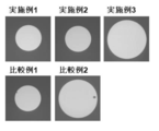
- FIG. 3 is an image showing a state of a non-polarizing part of a polarizer obtained in Examples 1 to 3 and Comparative Examples 1 and 2.
- FIG. It is a graph which compares and shows the generation
- A. Manufacturing method of polarizer includes making a basic solution contact an exposed part in the state coat
- a basic solution By bringing a basic solution into contact with the exposed portion, a non-polarizing portion is formed.
- it is provided with a resin film containing a dichroic substance and a surface protective film disposed on one side of the resin film, and the exposed resin film containing the dichroic substance is exposed on the one side.
- a polarizing film laminate having a part is used.
- FIG. 1 is a schematic cross-sectional view of a polarizing film laminate used in one embodiment of the present invention.
- the surface protective film 50 is detachably laminated on the resin film 10 containing a dichroic substance.
- the surface protective film 50 has a through hole 61.
- the polarizing film laminate 100 has an exposed portion 51 where the resin film 10 is exposed from the through hole 61.
- the surface protective film 50 is detachably laminated on the resin film 10 via any appropriate adhesive.
- a surface protection film may be provided as a layered product with an adhesive layer. In this case, for convenience, the surface protective film in the laminate may be referred to as a base film.
- the protective film 20 is laminated
- the protective film 20 can be used as it is as a protective film for a polarizing plate, which will be described later.
- the polarizing film laminate 100 even if another surface protective film 30 is peelably laminated on the surface where the surface protective film 50 having a through hole is not laminated (in the illustrated example, outside the protective film 20). Good.
- the polarizing film laminate is typically long.
- a step of contacting with a basic solution and a step of contacting with another treatment solution are continuously performed by immersion. be able to.
- the productivity of the polarizer can be further improved.
- the resin film containing the dichroic substance is a film that can be used as a polarizer.
- the dichroic substance include iodine and organic dyes. These may be used alone or in combination of two or more. Preferably iodine is used.
- a basic solution as described below the iodine complex is reduced and the content of iodine is reduced, resulting in the formation of a non-polarizing part with properties suitable for use as a part corresponding to a camera Because it can be done.
- PVA resin polyvinyl alcohol resin
- examples of the PVA resin include polyvinyl alcohol and ethylene-vinyl alcohol copolymer.
- Polyvinyl alcohol is obtained by saponifying polyvinyl acetate.
- the ethylene-vinyl alcohol copolymer can be obtained by saponifying an ethylene-vinyl acetate copolymer.
- the saponification degree of the PVA resin is usually 85 mol% or more and less than 100 mol%, preferably 95.0 mol% to 99.95 mol%, more preferably 99.0 mol% to 99.93 mol%. is there.
- the degree of saponification can be determined according to JIS K 6726-1994. By using a PVA-based resin having such a saponification degree, a polarizer having excellent durability can be obtained. If the degree of saponification is too high, there is a risk of gelation.
- the average degree of polymerization of the PVA resin can be appropriately selected according to the purpose.
- the average degree of polymerization is usually 1000 to 10,000, preferably 1200 to 4500, and more preferably 1500 to 4300.
- the average degree of polymerization can be determined according to JIS K 6726-1994.
- the thickness of the resin film containing the dichroic substance can be set to any appropriate value.
- the thickness is preferably 30 ⁇ m or less, more preferably 25 ⁇ m or less, still more preferably 20 ⁇ m or less, and particularly preferably less than 10 ⁇ m.
- the thickness is preferably 0.5 ⁇ m or more, more preferably 1 ⁇ m or more. If it is such thickness, a non-polarizing part can be favorably formed by making a basic solution contact. Furthermore, the time for contacting the basic solution can be shortened. Moreover, the thickness of the part contacted with the basic solution may be thinner than other parts. By using a thin resin film, it is possible to reduce the difference in thickness between the part that is in contact with the basic solution and the part that is not in contact with it. Can be done.
- the resin film containing the dichroic substance is a film that can be used as a polarizer.
- the resin film is subjected to various treatments such as a swelling treatment, a stretching treatment, a dyeing treatment with the dichroic substance, a crosslinking treatment, a washing treatment, and a drying treatment, so that the resin film can function as a polarizer. It is preferable.
- the resin film may be a resin layer formed on a substrate.
- the laminated body of a base material and a resin layer can be obtained by the method of apply
- the dyeing process is performed, for example, by immersing a resin film in a dyeing solution.
- a dyeing solution an aqueous iodine solution is preferably used.
- the amount of iodine is preferably 0.04 to 5.0 parts by weight per 100 parts by weight of water.
- an iodide is preferably used as the iodide.
- potassium iodide is preferably used as the iodide.
- the blending amount of iodide is preferably 0.3 to 15 parts by weight with respect to 100 parts by weight of water.
- the resin film is typically uniaxially stretched 3 to 7 times.
- the stretching direction can correspond to the absorption axis direction of the obtained polarizer.
- the surface protective film is used for the purpose of temporarily protecting the resin film in a step of contacting a basic solution described later. Accordingly, the surface protective film is clearly distinguished from a polarizer protective film (for example, the protective film 20 in the illustrated example).
- the surface protective film has a through hole corresponding to a portion corresponding to a desired shape of the non-polarizing portion (specifically, a portion corresponding to the exposed portion).
- the surface protective film is a laminate having a base film made of any appropriate resin and an adhesive layer provided on one surface of the base film, and the base film And a through-hole penetrating the pressure-sensitive adhesive layer.
- any appropriate forming material is used as the forming material of the base film.
- polyester resins such as polyethylene terephthalate resins, cycloolefin resins such as norbornene resins, olefin resins such as polyethylene and polypropylene, polyamide resins, polycarbonate resins, and copolymer resins thereof.
- a polyester resin particularly, a polyethylene terephthalate resin
- the elastic modulus is sufficiently high, and there is an advantage that deformation of the through hole hardly occurs even when tension is applied during transportation and / or bonding. .
- the thickness of the base film can be set to any appropriate value.
- the substrate film when used as a long polarizing film laminate, has a thickness of 30 ⁇ m to 150 ⁇ m because it has the advantage that deformation of the through-hole is difficult to occur even when tension is applied during transportation and / or bonding. There may be.
- a non-polarizing portion having a desired shape can be formed with high accuracy even when a thicker substrate film is used.
- the elastic modulus of the base film is preferably 2.2 kN / mm 2 to 4.8 kN / mm 2 . If the elastic modulus of the substrate film is in such a range, for example, when used as a long polarizing film laminate, the advantage that deformation of the through-hole hardly occurs even when tension is applied during transportation and / or bonding. Have The elastic modulus is measured according to JIS K 6781.
- the tensile elongation of the base film is preferably 90% to 170%.
- the tensile elongation is measured according to JIS K 6781.
- any appropriate pressure-sensitive adhesive can be adopted as long as the effects of the present invention can be obtained.
- the base resin for the pressure-sensitive adhesive include acrylic resins, styrene resins, and silicone resins. Acrylic resins are preferred from the viewpoints of chemical resistance, adhesion for preventing the treatment liquid from entering during immersion, flexibility in the adherend, and the like.
- the pressure-sensitive adhesive may contain a crosslinking agent, and examples of the crosslinking agent that can be included in the pressure-sensitive adhesive include isocyanate compounds, epoxy compounds, and aziridine compounds.
- the pressure-sensitive adhesive may contain, for example, a silane coupling agent. The formulation of the pressure-sensitive adhesive can be appropriately set according to the purpose.
- the pressure-sensitive adhesive layer can be formed by any appropriate method. Specific examples include a method of applying a pressure-sensitive adhesive solution on a base film and drying, a method of forming a pressure-sensitive adhesive layer on a separator, and transferring the pressure-sensitive adhesive layer to the base film. Examples of the coating method include roll coating methods such as reverse coating and gravure coating, spin coating methods, screen coating methods, fountain coating methods, dipping methods, and spray methods.
- the thickness of the pressure-sensitive adhesive layer is preferably 5 ⁇ m to 60 ⁇ m, more preferably 5 ⁇ m to 30 ⁇ m. If the thickness is too thin, the adhesiveness becomes insufficient, and bubbles or the like may enter the adhesive interface. If the thickness is too thick, problems such as sticking out of the adhesive easily occur.
- the thickness of the pressure-sensitive adhesive layer can be adjusted to an appropriate range together with the thickness of the base film.
- Arbitrary appropriate shape can be employ
- Specific examples include a circle, an ellipse, a square, a rectangle, and a rhombus.
- a non-polarizing portion having a desired shape can be formed with high accuracy. Therefore, the shape of the through hole of the surface protective film may be a more complicated shape (for example, a star shape).
- the through-holes in the surface protection film may be smaller in size.
- the diameter may be 2.9 mm or less.
- the through hole of the surface protective film can be formed by, for example, mechanical punching (for example, punching, engraving blade punching, plotter, water jet) or removal of a predetermined portion of the surface protective film (for example, laser ablation or chemical dissolution).
- another surface protective film (specifically, the surface protective film 30 in FIG. 1) may be further laminated on the side where the surface protective film is not disposed.
- the other surface protective film is formed of any appropriate forming material.
- the above-described surface protective film forming material may be used, or other resin such as polyolefin (for example, polyethylene) may be used.
- polyolefin for example, polyethylene
- surface protective films may be laminated
- a resin film containing iodine is preferably used as the resin film containing a dichroic substance.
- the iodine content can be reduced by bringing a basic solution into contact with the exposed portion, and as a result, a non-polarized portion can be selectively formed only in the exposed portion. Therefore, a non-polarizing part can be selectively formed in a desired part of the resin film with very high production efficiency without complicated operation.
- the iodine complex is formed again with the use of the polarizer, and the non-polarizing part has the desired characteristics. There is a risk of not having it.
- the content of iodine itself is low, the transparency of the non-polarizing part is maintained better than when the non-polarizing part is formed by decomposing the iodine complex with laser light or the like.
- the formation of the non-polarizing part by the basic solution will be described in detail.
- the basic solution penetrates into the exposed portion.
- the iodine complex contained in the exposed part is reduced by the base contained in the basic solution to become iodine ions.
- the polarization performance of the exposed portion is substantially lost, and a non-polarized portion is formed in the exposed portion.
- permeability of an exposed part improves by reduction
- a non-polarizing portion is selectively formed in a predetermined portion of the resin film, and the non-polarizing portion becomes stable even under humidified conditions.
- the surface protection film forming material, thickness and mechanical properties, the concentration of the basic solution, and the time for which the basic solution is brought into contact with the exposed portion the basic solution penetrates to an undesired portion. (As a result, it is possible to prevent a non-polarizing part from being formed in an undesired part).
- the step of bringing the basic solution into contact with the exposed portion can be performed by any appropriate means. For example, dropping of a basic solution, coating, spraying, immersion in a basic solution, and the like can be given.
- a basic solution for example, dropping of a basic solution, coating, spraying, immersion in a basic solution, and the like can be given.
- the immersion in the basic solution is preferably performed as follows: a long polarizing film laminate in which the surface protective film is laminated on one side of the resin film and the other surface protective film is laminated on the other side. The body is immersed in a basic solution while transporting the polarizing film laminate.
- the surface modification is performed on the exposed part at the time of contact.
- a treatment and / or setting the contact angle between the exposed portion and the basic solution to 50 degrees or less (particularly preferably, the exposed portion is subjected to a surface modification treatment upon contact). Floating island defects can be effectively reduced.
- any appropriate basic compound can be used as the basic compound contained in the basic solution.
- Examples of basic compounds include hydroxides of alkali metals such as sodium hydroxide, potassium hydroxide and lithium hydroxide, hydroxides of alkaline earth metals such as calcium hydroxide, inorganic alkali metal salts such as sodium carbonate, acetic acid Organic alkali metal salts such as sodium, aqueous ammonia and the like can be mentioned.
- the basic compound contained in the basic solution is preferably an alkali metal hydroxide, more preferably sodium hydroxide, potassium hydroxide, or lithium hydroxide.
- any appropriate solvent can be used as the solvent of the basic solution.
- Specific examples include water, alcohols such as ethanol and methanol, ethers, benzene, chloroform, and mixed solvents thereof.
- the solvent is preferably water or alcohol since the dichroic substance is well transferred to the solvent.
- the concentration of the basic solution is, for example, 0.01N to 5N, preferably 0.05N to 3N, and more preferably 0.1N to 2.5N. If the concentration of the basic solution is in such a range, the content of the dichroic substance can be efficiently reduced, and the reduction of the content of the dichroic substance in a part other than the exposed part is prevented. be able to.
- the liquid temperature of the basic solution is, for example, 20 ° C. to 50 ° C.
- the time for bringing the basic solution into contact with the exposed portion can be set according to the thickness of the resin film, the type of the basic compound contained in the basic solution, and the concentration of the basic solution. 30 minutes.
- the basic solution can be removed by any appropriate means as necessary after contacting the exposed portion (after formation of the non-polarizing portion).
- Specific examples of the method for removing the basic solution include wiping removal with a waste cloth, suction removal, natural drying, heat drying, air drying, vacuum drying, washing, and the like.
- the drying temperature when the basic solution is removed by drying is, for example, 20 ° C. to 100 ° C.
- the exposed portion When exposed, the exposed portion is subjected to surface modification treatment.
- the basic solution is easily wetted and spreads, and the non-polarized portion can be formed uniformly.
- a non-polarizing portion having a desired shape can be formed with high accuracy.
- a non-polarized portion having a desired shape can be formed with high accuracy without adding an additive (for example, an organic solvent such as alcohol) to the basic solution.
- an additive for example, an organic solvent such as alcohol
- drainage facilities for additives for example, organic solvents
- the production method of the present invention is preferable from the viewpoint of cost reduction and environmental consideration in the production facility.
- the surface modification treatment on the exposed portion is performed at any appropriate stage.
- the surface modification treatment of the resin film may be performed on the entire resin film, or may be performed only on a desired portion (for example, a portion corresponding to the exposed portion).
- the surface modification treatment is performed on the exposed portion.
- the surface modification treatment is performed on the exposed portion of the resin film covered with the surface protective film.
- the surface modification treatment is performed on the entire resin film.
- the resin film that has been subjected to the surface modification treatment is covered with a surface protective film. From the viewpoint that the surface modification treatment can be easily performed on a desired portion, it is preferable to perform the surface modification treatment on the resin film coated with the surface protective film.
- any appropriate method can be used as the surface modification treatment method. Examples include corona treatment, plasma treatment, vacuum UV irradiation, and application of a diluted solution obtained by diluting a surface modifier such as a silane coupling agent with any appropriate solvent.
- a surface modifier such as a silane coupling agent
- corona treatment or application of a diluent for the surface modifier is preferable.
- Corona treatment can be performed under any suitable conditions.
- the corona discharge electron dose is preferably 10 to 500 W / m 2 / min, more preferably 30 to 300 W / m 2 / min.
- any appropriate surface modifier can be used as the surface modifier.
- a silane coupling agent etc. are mentioned.
- the silane coupling agent include an organosilane compound having at least one functional group selected from the group consisting of an epoxy group, an acrylic group, a methacryl group, an amino group, an isocyanate group, and a mercapto group. Only one type of surface modifier may be used, or two or more types may be used in combination.
- organosilane compound having an epoxy group examples include 2- (3,4-epoxycyclohexyl) ethyltrimethoxysilane, 3-glycidoxypropylmethyldimethoxysilane, and 3-glycidoxypropyltrimethoxy. Examples thereof include silane, 3-glycidoxypropylmethyldiethoxysilane, and 3-glycidoxypropyltriethoxysilane. Examples of the organosilane compound having an acrylic group include 3-acryloxypropyltrimethoxysilane, 3-acryloxypropyltriethoxysilane, and the like.
- organosilane compound having a methacryl group examples include 3-methacryloxypropylmethyldimethoxysilane, 3-methacryloxypropyltrimethoxysilane, 3-methacryloxypropylmethyldiethoxysilane, and 3-methacryloxypropyltriethoxysilane.
- organosilane compound having an amino group examples include N-2- (aminoethyl) -3-aminopropylmethyldimethoxysilane, N-2- (aminoethyl) -3-aminopropyltrimethoxysilane, and 3-aminopropyl.
- organosilane compound having an isocyanate group include 3-isocyanatopropyltriethoxysilane and 3-isocyanatepropyltrimethoxysilane.
- organosilane compound having a mercapto group include 3-mercaptopropylmethyldimethoxysilane and 3-mercaptopropyltrimethoxysilane.
- a commercially available product may be used as the silane coupling agent.
- Examples of commercially available products include “KBM series” and “KBE series” manufactured by Shin-Etsu Chemical Co., Ltd.
- any appropriate solvent can be used as the solvent.
- a silane coupling agent water, methanol, ethanol, etc. can be used suitably.
- Any appropriate method can be used as a coating method. Examples thereof include roll coating methods such as reverse coating and gravure coating, spin coating methods, screen coating methods, fountain coating methods, dipping methods, and spraying methods.
- the content of the surface modifier in the diluent may be set to any appropriate value.
- the content of the surface modifier is, for example, 0.1 to 10 parts by weight, preferably 1 to 5 parts by weight with respect to 100 parts by weight of the solvent.
- the exposed portion can have appropriate wettability. If the content of the surface modifier is too small, a sufficient surface modification effect may not be obtained. Moreover, when there is too much content of a surface modifier, a malfunction may arise in the external appearance of the polarizer obtained.
- the contact angle between the exposed portion and the basic solution is 50 degrees or less.
- the basic solution can be sufficiently contacted (spread) to the end of the exposed portion.
- the contact angle between the exposed portion and the basic solution is preferably 40 degrees or less, and more preferably 35 degrees or less.
- the contact angle between the exposed portion and the basic solution is in such a range, the affinity between the exposed portion and the basic solution can be further improved, and the basic solution can be brought into better contact with the exposed portion. .
- the contact angle between the exposed portion and the basic solution can be measured by a droplet method at 25 ° C. using a contact angle meter.
- Arbitrary appropriate methods are mentioned as a method of making the contact angle of an exposed part and a basic solution 50 degrees or less.
- surface modification of a resin film for example, an exposed part
- addition of any appropriate additive to a basic solution can be mentioned. These methods may be used alone or in combination of two or more.
- the surface modification of the resin film is as described above as the surface modification treatment.
- any appropriate additive can be used, and examples thereof include a surfactant.
- Surfactants include anionic surfactants such as sodium alkylsulfate and sodium alkylsulfonate, cationic surfactants such as alkyltrimethylammonium chloride and dialkyldimethylammonium chloride, polyoxyethylene alkyl ether, polyoxyethylene sorbitan
- Nonionic surfactants such as fatty acid esters, amphoteric surfactants and the like can be mentioned.
- Stearyltrimethylammonium chloride and cetyltrimethylammonium chloride are preferable. By using these surfactants, the contact angle can be reduced more favorably. Only one surfactant may be used, or two or more surfactants may be used in combination.
- the amount of additive added to the basic solution can be set to any appropriate value so that the contact angle is 50 degrees or less.
- the addition amount is, for example, 0.1 to 10 parts by weight, preferably 0.5 to 3 parts by weight, with respect to 100 parts by weight of the solvent of the basic solution. If the amount added is too small, the contact angle may not be sufficiently small. When the addition amount is too large, a defect may occur in the appearance of the obtained polarizer.
- the method for producing a polarizer of the present invention may further include any appropriate step other than the step of bringing the basic solution into contact with the exposed portion. Examples of other steps include a step of contacting with an acidic solution and a washing step.
- the production method of the present invention may further include a step of contacting with an acidic solution.
- a step of contacting with an acidic solution By further including the step of contacting with an acidic solution, it is possible to stably maintain a non-polarized portion having a desired size even under humidified conditions.
- the step of contacting with the acidic solution can be performed, for example, after the step of contacting with the basic solution.
- any appropriate acidic compound can be used as the acidic compound contained in the acidic solution.
- the acidic compound include inorganic acids such as hydrochloric acid, sulfuric acid, nitric acid, and hydrogen fluoride, and organic acids such as formic acid, oxalic acid, citric acid, acetic acid, and benzoic acid.
- the concentration of the acidic solution is, for example, 0.01N to 5N, preferably 0.05N to 3N, and more preferably 0.1N to 2.5N.
- the same conditions as those that can be employed in the step of contacting with the basic solution can be employed.
- the production method of the present invention may further include a cleaning step.
- the cleaning process may be performed only once or a plurality of times.
- the cleaning process may be performed at any suitable stage in the polarizer manufacturing process. For example, after washing the resin film contacted with the basic solution with any appropriate liquid, it may be contacted with the acidic solution, and after performing the step of contacting the basic solution and the step of contacting the acidic solution, A washing step with any suitable liquid may be performed.
- any appropriate liquid can be used as the liquid used for cleaning.
- examples thereof include pure water, alcohols such as methanol and ethanol, acidic aqueous solutions, and mixed solvents thereof.
- the temperature of the liquid to be used can be set to any appropriate temperature.
- the polarizer obtained by the method of the present invention may have a non-polarizing portion having a desired shape and size formed with high accuracy. Therefore, the polarizer of the present invention can have excellent functionality and design.
- a polarizer having a non-polarizing portion can be applied to, for example, an image display device including a camera. This is because even when a smaller non-polarizing portion is formed, the camera can sufficiently exhibit the photographing function and the appearance of the obtained image display device can be excellent.
- a non-polarization part is circular and the diameter is 2.9 mm or less. Even if the polarizer of the present invention has such a small non-polarizing portion, a desired shape can be formed with high accuracy.
- the roundness of the non-polarizing part is preferably 0.060 mm or less, and more preferably 0.030 mm or less.
- the roundness is within the above range, the non-polarizing portion is closer to a perfect circle and is formed with high accuracy. Therefore, for example, even when a smaller non-polarizing part is required as a camera part, it is possible to prevent a decrease in camera performance due to insufficient decolorization.
- the roundness is the difference in radius between the circle that is concentric and circumscribed to the circle that has the smallest sum of squares of deviation with respect to the shape of the measured non-polarization part (the roundness by the least square center method) Degree).
- the transmittance of the non-polarizing part is preferably 50% or more, more preferably 60% or more, and further preferably 75% or more. Yes, particularly preferably 90% or more. With such transmittance, desired transparency as a non-polarizing portion can be ensured. As a result, when the polarizer is arranged so that the non-polarizing part corresponds to the camera part of the image display device, it is possible to prevent an adverse effect on the photographing performance of the camera.
- the occurrence of floating island defects is preferably suppressed in the non-polarizing part, and more preferably, the non-polarizing part is substantially free of floating island defects.
- the floating island-shaped defect means a portion having a low transmittance due to a decoloration failure in the non-polarized portion.
- the non-polarizing part has a minimum relative transmittance of, for example, 60.0% or more, preferably 65.0% or more, among the relative transmittances measured for each pixel (typically 5 ⁇ m ⁇ 5 ⁇ m). .
- the incidence of floating island defects in the non-polarizing part is, for example, 0.8% or less.
- the relative transmittance means that the average luminance of the decolored part (non-polarized part) is 100%, the average luminance of the non-decolored part (part other than the non-polarized part) is 0%, and the non-polarized part has 256 gradations. It is displayed in gray scale and converted to transmittance.
- surface modification treatment is effective, and corona treatment can be particularly effective.
- Polarizing plate A polarizer can be provided practically as a polarizing plate.
- the polarizing plate has a polarizer and a protective film disposed on at least one side of the polarizer.
- the polarizing plate has an adhesive layer as the outermost layer.
- the pressure-sensitive adhesive layer is typically the outermost layer on the image display device side.
- a separator can be temporarily attached to the pressure-sensitive adhesive layer in a peelable manner.
- the material for forming the protective film examples include cellulose resins such as diacetyl cellulose and triacetyl cellulose, (meth) acrylic resins, cycloolefin resins, olefin resins such as polypropylene, and ester resins such as polyethylene terephthalate resins. , Polyamide resins, polycarbonate resins, copolymer resins thereof, and the like.
- the thickness of the protective film is preferably 10 ⁇ m to 100 ⁇ m.
- the protective film is typically laminated on the polarizer via an adhesive layer (specifically, an adhesive layer or an adhesive layer).
- the adhesive layer is typically formed of a PVA adhesive or an active energy ray curable adhesive.
- the pressure-sensitive adhesive layer is typically formed of an acrylic pressure-sensitive adhesive.
- the polarizing plate may further have any appropriate optical functional layer depending on the purpose.
- the optical functional layer include a retardation film (optical compensation film) and a surface treatment layer.
- the protective film may have an optical compensation function (specifically, it may have an appropriate refractive index ellipsoid, an in-plane retardation, and a thickness direction retardation depending on the purpose). ).
- the surface treatment layer can be disposed on the viewing side of the polarizing plate.
- Typical examples of the surface treatment layer include a hard coat layer, an antireflection layer, and an antiglare layer.
- An image display device of the present invention includes the polarizer.
- the image display device include a liquid crystal display device and an organic EL device.
- the liquid crystal display device includes a liquid crystal panel including a liquid crystal cell and the polarizer disposed on one side or both sides of the liquid crystal cell.
- the organic EL device includes an organic EL panel in which the polarizer is disposed on the viewing side.
- the polarizer may be disposed so as to correspond to the camera unit of the image display device on which the non-polarizing unit is mounted.
- a perfect circle inscribed circle and circumscribed circle in contact with the non-polarized portion approximate circle and its center were calculated using the least square method. Measure the distance (specifically, radius) from the calculated center of each perfect circle to the circumference of the approximate non-polarization part circle, and the difference between the part where the distance is the maximum and the part where the distance is the minimum (roundness) was calculated. If the roundness is 0.060 mm or less, it can be suitably used for applications such as image display devices. [Minimum relative transmittance in non-polarization part (evaluation of floating island defects)] An inscribed circle was drawn using the center / minimum radius of the circle calculated by the roundness measurement.
- the average luminance value of the polarizer is defined as 0%
- the average luminance value in the inscribed circle is defined as 100%
- the luminance value in the inscribed circle is determined for each pixel (about 5 ⁇ m ⁇ about 5 ⁇ m)
- the transmittance was calculated.
- the lowest relative transmittance within the inscribed circle was defined as the minimum relative transmittance. Typically, when the minimum transmittance is less than 60.0%, the portion can be recognized as a floating island defect.
- Example 1 Using a picnal blade on a resin film with an adhesive (PET resin film, thickness 38 ⁇ m, thickness of the adhesive layer: 5 ⁇ m), a circular through hole with a diameter of 1.9 mm was provided to obtain a surface protective film having a through hole. .
- the obtained surface protective film is bonded to the polarizer side surface of a polarizing plate (polarizer (transmittance 42.3%, thickness 5 ⁇ m) / protective film (thickness 25 ⁇ m)) with a total thickness of 30 ⁇ m via an adhesive layer.
- a polarizing film laminate was obtained.
- the exposed part of the obtained polarizing film laminate was subjected to corona discharge treatment (corona discharge electron irradiation amount: 100 W / m 2 / min) using a table-type corona treatment apparatus (manufactured by Kasuga Electric). After the corona discharge treatment, the contact angle between the exposed portion and water was measured with a contact angle meter (manufactured by Kyowa Interface Science) by the droplet method. The measured contact angle value was 28 degrees. Next, a basic solution at normal temperature (sodium hydroxide aqueous solution, 0.1 mol / L (0.1N)) was dropped onto the exposed portion of the polarizing film laminate, and left for 1 minute.
- Example 2 1 part by weight of a silane coupling agent (trade name: KBM-303, manufactured by Shin-Etsu Chemical Co., Ltd.) was mixed with 99 parts by weight of a solvent (ethanol) to obtain a diluted solution.
- a polarizer having a non-polarizing part was obtained in the same manner as in Example 1 except that the obtained diluted solution was applied to the exposed part and dried. After application and drying of the diluted solution, the contact angle between the exposed portion and water was measured with a contact angle meter (manufactured by Kyowa Interface Science) by the droplet method. The contact angle between the exposed part and water was 45 degrees. The roundness and the minimum relative transmittance of the non-polarizing part of the obtained polarizer were measured. The results are shown in Table 1. Furthermore, an image showing the state of the non-polarizing portion is shown in FIG.
- Example 3 Using a picnal blade on a long resin film with pressure-sensitive adhesive (PET resin film, thickness 38 ⁇ m, thickness of the pressure-sensitive adhesive layer: 5 ⁇ m), a circular through hole with a diameter of 2.8 mm is provided to protect the surface having the through hole. A film was obtained. Moreover, the said long resin film with an adhesive was used as it was, and it was set as the other surface protection film.
- PET resin film thickness 38 ⁇ m, thickness of the pressure-sensitive adhesive layer: 5 ⁇ m
- the surface protective film on the polarizer side surface of a long polarizing plate (polarizer (transmittance: 42.3%, thickness: 5 ⁇ m) / protective film (thickness: 25 ⁇ m)) having a total thickness of 30 ⁇ m and protection of the polarizing plate
- the other surface protective film was bonded to the film side surface by roll-to-roll to obtain a long polarizing film laminate.
- the exposed portion of the obtained long polarizing film laminate was subjected to corona discharge treatment (corona discharge electron irradiation amount: 120 W / m 2 / min) using a corona treatment device (Kasuga Denki). .
- the contact angle between the exposed portion and water was measured with a contact angle meter (manufactured by Kyowa Interface Science) by the droplet method.
- the measured contact angle value was 32 degrees.
- the polarizing film laminate with the adhesive-attached resin film facing downward was immersed (15 seconds) in a basic solution at normal temperature (aqueous sodium hydroxide solution, 2 mol / L (2N)) while being conveyed.
- aqueous sodium hydroxide solution 2 mol / L (2N)
- the attached aqueous sodium hydroxide solution was washed and dried to obtain a polarizer having a non-polarizing part.
- the roundness and the minimum relative transmittance of the non-polarizing part of the obtained polarizer were measured. The results are shown in Table 1.
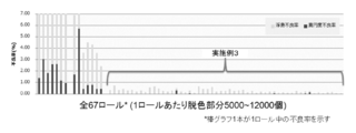
- FIG. 3 shows the defect rate when 53 rolls (long polarizing film laminate) are continuously produced under the same conditions together with the result of Comparative Example 2. A roundness of 0.040 mm or more or a minimum relative transmittance of less than 60.0% was judged as defective.
- Example 1 A polarizer having a non-polarizing part was obtained in the same manner as in Example 1 except that the surface modification treatment was not performed on the exposed part.
- the contact angle between the untreated exposed portion and water was 62 degrees.
- the roundness and the minimum relative transmittance of the non-polarizing part of the obtained polarizer were measured. The results are shown in Table 1. Furthermore, an image showing the state of the non-polarizing portion is shown in FIG.
- Example 2 A polarizer having a non-polarizing portion was obtained in the same manner as in Example 3 except that the exposed portion was not subjected to surface modification treatment. The contact angle between the untreated exposed part and water was 63 degrees. The roundness and the minimum relative transmittance of the non-polarizing part of the obtained polarizer were measured. The results are shown in Table 1. Furthermore, an image showing the state of the non-polarizing portion is shown in FIG. Moreover, the defect rate when continuously producing 14 rolls (long polarizing film laminate) under the same conditions is shown in FIG. 3 together with the results of Example 3.
- a polarizer having a non-polarizing part excellent in both roundness and minimum relative transmittance can be obtained.
- Examples 1 and 2 where the exposed portion was subjected to a surface modification treatment and a contact step with a basic solution was performed, although the non-polarizing portion was 1.9 mm in diameter and small in size, The desired non-polarizing part was formed with high accuracy.
- Comparative Example 1 in which the surface modification treatment was not performed and the contact step with the basic solution was performed, the shape of the non-polarizing portion became irregular and there was room for improvement. Further, as apparent from a comparison between Example 3 and Comparative Example 2, it was found that by performing the surface modification treatment, floating island defects were suppressed and the defect rate was significantly reduced.
- the polarizer of the present invention is suitably used for a mobile phone such as a smartphone, an image display device with a camera (liquid crystal display device, organic EL device) such as a notebook PC or tablet PC.
- a mobile phone such as a smartphone
- an image display device with a camera liquid crystal display device, organic EL device
- a notebook PC or tablet PC such as a notebook PC or tablet PC.
Landscapes
- Physics & Mathematics (AREA)
- Chemical & Material Sciences (AREA)
- Optics & Photonics (AREA)
- General Physics & Mathematics (AREA)
- Polymers & Plastics (AREA)
- Organic Chemistry (AREA)
- Health & Medical Sciences (AREA)
- Medicinal Chemistry (AREA)
- Chemical Kinetics & Catalysis (AREA)
- General Chemical & Material Sciences (AREA)
- Engineering & Computer Science (AREA)
- Plasma & Fusion (AREA)
- Thermal Sciences (AREA)
- Nonlinear Science (AREA)
- Mathematical Physics (AREA)
- Crystallography & Structural Chemistry (AREA)
- Polarising Elements (AREA)
Abstract
Description
1つの実施形態においては、本発明の偏光子の製造方法は、上記表面保護フィルムで被覆された樹脂フィルムに、表面改質処理を施すことを含む。
1つの実施形態においては、上記表面改質処理はコロナ処理である。
1つの実施形態においては、上記表面改質処理は表面改質剤の塗布である。
1つの実施形態においては、上記表面改質剤はオルガノシラン化合物である。
1つの実施形態においては、上記露出部と上記塩基性溶液との接触角は50度以下である。
本発明の偏光子の別の製造方法は、二色性物質を含む樹脂フィルムの少なくとも一部が露出するよう表面保護フィルムで被覆された状態で、該露出部に塩基性溶液を接触させることを含み、該露出部と該塩基性溶液との接触角が50度以下である。
1つの実施形態においては、上記塩基性溶液は添加剤をさらに含む。
1つの実施形態においては、上記接触は、上記樹脂フィルムの上記表面保護フィルムと反対側の面が別の表面保護フィルムで被覆された状態で、該樹脂フィルムを搬送しながら上記塩基性溶液に浸漬することにより行われる。
本発明の別の局面によれば、偏光子が提供される。この偏光子は、円形で、かつ、直径が2.9mm以下である非偏光部を有する。
1つの実施形態においては、上記非偏光部の真円度は0.060mm以下である。 The manufacturing method of the polarizer of this invention includes making a basic solution contact this exposed part in the state coat | covered with the surface protection film so that at least one part of the resin film containing a dichroic substance might be exposed. At the time of the contact, the exposed portion is subjected to a surface modification treatment.
In one embodiment, the method for producing a polarizer of the present invention includes subjecting a resin film covered with the surface protective film to a surface modification treatment.
In one embodiment, the surface modification treatment is a corona treatment.
In one embodiment, the surface modification treatment is application of a surface modifier.
In one embodiment, the surface modifier is an organosilane compound.
In one embodiment, the contact angle between the exposed portion and the basic solution is 50 degrees or less.
Another manufacturing method of the polarizer of the present invention is to bring a basic solution into contact with the exposed portion in a state where at least a part of the resin film containing the dichroic material is covered with a surface protective film. And the contact angle between the exposed portion and the basic solution is 50 degrees or less.
In one embodiment, the basic solution further comprises an additive.
In one embodiment, the contact is immersed in the basic solution while transporting the resin film in a state where the surface of the resin film opposite to the surface protective film is covered with another surface protective film. Is done.
According to another aspect of the present invention, a polarizer is provided. This polarizer has a non-polarizing part which is circular and has a diameter of 2.9 mm or less.
In one embodiment, the roundness of the non-polarizing part is 0.060 mm or less.
本発明の製造方法は、二色性物質を含む樹脂フィルムの少なくとも一部が露出するよう表面保護フィルムで被覆された状態で、露出部に塩基性溶液を接触させることを含む。露出部に塩基性溶液を接触させることにより、非偏光部が形成される。1つの実施形態では、二色性物質を含む樹脂フィルムと該樹脂フィルムの一方面側に配置された表面保護フィルムとを備え、該一方面側に二色性物質を含む樹脂フィルムが露出した露出部を有する偏光フィルム積層体が用いられる。 A. Manufacturing method of polarizer The manufacturing method of this invention includes making a basic solution contact an exposed part in the state coat | covered with the surface protection film so that at least one part of the resin film containing a dichroic substance might be exposed. . By bringing a basic solution into contact with the exposed portion, a non-polarizing portion is formed. In one embodiment, it is provided with a resin film containing a dichroic substance and a surface protective film disposed on one side of the resin film, and the exposed resin film containing the dichroic substance is exposed on the one side. A polarizing film laminate having a part is used.
上記二色性物質を含む樹脂フィルムは、偏光子として使用し得るフィルムである。上記二色性物質としては、例えば、ヨウ素、有機染料等が挙げられる。これらは、単独で用いてもよく、2種以上組み合わせて用いてもよい。好ましくはヨウ素が用いられる。後述するように塩基性溶液に接触させることにより、ヨウ素錯体が還元されてヨウ素の含有量が低減され、その結果、カメラに対応する部分として使用するのに適切な特性を有する非偏光部を形成することができるからである。 (Resin film containing dichroic material)
The resin film containing the dichroic substance is a film that can be used as a polarizer. Examples of the dichroic substance include iodine and organic dyes. These may be used alone or in combination of two or more. Preferably iodine is used. By contacting with a basic solution as described below, the iodine complex is reduced and the content of iodine is reduced, resulting in the formation of a non-polarizing part with properties suitable for use as a part corresponding to a camera Because it can be done.
表面保護フィルムは、後述する塩基性溶液を接触させる工程で、上記樹脂フィルムを一時的に保護することを目的として用いられる。したがって、表面保護フィルムは、偏光子の保護フィルム(例えば、図示例の保護フィルム20)と明確に区別される。例えば、表面保護フィルムは、所望の非偏光部の形状に対応する部分(具体的には、露出部に相当する部分)に対応する貫通孔が形成される。1つの実施形態においては、表面保護フィルムは、任意の適切な樹脂からなる基材フィルムと該基材フィルムの一方の面に設けられた粘着剤層とを有する積層体であり、該基材フィルムと該粘着剤層とを貫通する貫通孔を有する。 (Surface protection film)
The surface protective film is used for the purpose of temporarily protecting the resin film in a step of contacting a basic solution described later. Accordingly, the surface protective film is clearly distinguished from a polarizer protective film (for example, the
樹脂フィルム(具体的には、露出部)に塩基性溶液を接触させることにより、樹脂フィルムが脱色され、該脱色により非偏光部が形成され得る。上述の通り、二色性物質を含む樹脂フィルムとしては、ヨウ素を含む樹脂フィルムが好ましく用いられる。二色性物質としてヨウ素を含む場合、露出部に塩基性溶液を接触させることにより、ヨウ素含有量を低減させ、結果として、露出部のみに選択的に非偏光部を形成することができる。そのため、複雑な操作を伴うことなく非常に高い製造効率で、樹脂フィルムの所望の部分に選択的に非偏光部を形成することができる。なお、非偏光部にヨウ素が残存している場合、ヨウ素錯体を破壊して非偏光部を形成したとしても、偏光子の使用に伴い再度ヨウ素錯体が形成され、非偏光部が所望の特性を有さなくなるおそれがある。本実施形態では、ヨウ素自体の含有量が低いので、レーザー光等によりヨウ素錯体を分解して非偏光部が形成されている場合に比べて、非偏光部の透明性が良好に維持される。 (Contact with basic solution)
By bringing the basic solution into contact with the resin film (specifically, the exposed portion), the resin film is decolored, and the depolarized portion can be formed by the decoloration. As described above, a resin film containing iodine is preferably used as the resin film containing a dichroic substance. When iodine is contained as a dichroic substance, the iodine content can be reduced by bringing a basic solution into contact with the exposed portion, and as a result, a non-polarized portion can be selectively formed only in the exposed portion. Therefore, a non-polarizing part can be selectively formed in a desired part of the resin film with very high production efficiency without complicated operation. When iodine remains in the non-polarizing part, even if the iodine complex is destroyed to form the non-polarizing part, the iodine complex is formed again with the use of the polarizer, and the non-polarizing part has the desired characteristics. There is a risk of not having it. In this embodiment, since the content of iodine itself is low, the transparency of the non-polarizing part is maintained better than when the non-polarizing part is formed by decomposing the iodine complex with laser light or the like.
本発明の偏光子の製造方法は、露出部に塩基性溶液を接触させる工程以外の任意の適切な工程をさらに含んでいてもよい。他の工程としては、例えば、酸性溶液に接触させる工程、洗浄工程等が挙げられる。 (Other processes)
The method for producing a polarizer of the present invention may further include any appropriate step other than the step of bringing the basic solution into contact with the exposed portion. Examples of other steps include a step of contacting with an acidic solution and a washing step.
本発明の方法により得られる偏光子は、高精度で形成された所望の形状およびサイズの非偏光部を有し得る。そのため、本発明の偏光子は、優れた機能性およびデザイン性を有し得る。 B. Polarizer Having Non-Polarizing Portion The polarizer obtained by the method of the present invention may have a non-polarizing portion having a desired shape and size formed with high accuracy. Therefore, the polarizer of the present invention can have excellent functionality and design.
偏光子は、実用的には偏光板として提供され得る。偏光板は、偏光子と偏光子の少なくとも一方の側に配置された保護フィルムとを有する。実用的には、偏光板は、最外層として粘着剤層を有する。粘着剤層は、代表的には画像表示装置側の最外層となる。粘着剤層には、セパレーターが剥離可能に仮着され得る。 C. Polarizing plate A polarizer can be provided practically as a polarizing plate. The polarizing plate has a polarizer and a protective film disposed on at least one side of the polarizer. Practically, the polarizing plate has an adhesive layer as the outermost layer. The pressure-sensitive adhesive layer is typically the outermost layer on the image display device side. A separator can be temporarily attached to the pressure-sensitive adhesive layer in a peelable manner.
本発明の画像表示装置は、上記偏光子を備える。画像表示装置としては、例えば、液晶表示装置、有機ELデバイスが挙げられる。具体的には、液晶表示装置は、液晶セルと、この液晶セルの片側もしくは両側に配置された上記偏光子とを含む液晶パネルを備える。有機ELデバイスは、視認側に上記偏光子が配置された有機ELパネルを備える。偏光子は、非偏光部が搭載される画像表示装置のカメラ部に対応するように配置され得る。 D. Image Display Device An image display device of the present invention includes the polarizer. Examples of the image display device include a liquid crystal display device and an organic EL device. Specifically, the liquid crystal display device includes a liquid crystal panel including a liquid crystal cell and the polarizer disposed on one side or both sides of the liquid crystal cell. The organic EL device includes an organic EL panel in which the polarizer is disposed on the viewing side. The polarizer may be disposed so as to correspond to the camera unit of the image display device on which the non-polarizing unit is mounted.
[真円度]
最小二乗中心法により、真円度を測定した。測定には、超高速フレキシブル画像処理システム(キーエンス社製、商品名:XG-7500)を用いた。偏光子の非偏光部をカメラ(測定距離:250mm、測定角:90°)で撮像した。撮像した画像からエッジ検出を行い、円(以下、非偏光部近似円ともいう)を描画した。次いで、最小二乗法を用いて、非偏光部近似円に接する真円(内接円および外接円)、ならびに、その中心を算出した。算出した各真円の中心から非偏光部近似円の周までの距離(具体的には、半径)を測定し、該距離が最大となる部分と最小となる部分との差(真円度)を算出した。真円度が0.060mm以下であれば、画像表示装置等の用途に好適に用いることができる。
[非偏光部における最小相対透過率(浮島状欠点の評価)]
上記真円度測定にて算出した円の中心・最小半径を用いて内接円を描画した。次いで、偏光子部分の平均輝度値を0%、内接円内における平均輝度値を100%と定義し、内接円内の輝度値を1画素 (約5μm×約5μm) ごとに求め、相対透過率を算出した。内接円内における最も低い相対透過率を最小相対透過率として定義した。代表的には最小透過率が60.0%未満である場合には、その部分が浮島状欠点として認識され得る。 EXAMPLES Hereinafter, although an Example demonstrates this invention concretely, this invention is not limited by these Examples. The evaluation method used in this example is as follows.
[Roundness]
Roundness was measured by the least square center method. For the measurement, an ultra-high speed flexible image processing system (manufactured by Keyence Corporation, trade name: XG-7500) was used. The non-polarizing part of the polarizer was imaged with a camera (measurement distance: 250 mm, measurement angle: 90 °). Edge detection was performed from the captured image, and a circle (hereinafter also referred to as a non-polarized portion approximate circle) was drawn. Next, a perfect circle (inscribed circle and circumscribed circle) in contact with the non-polarized portion approximate circle and its center were calculated using the least square method. Measure the distance (specifically, radius) from the calculated center of each perfect circle to the circumference of the approximate non-polarization part circle, and the difference between the part where the distance is the maximum and the part where the distance is the minimum (roundness) Was calculated. If the roundness is 0.060 mm or less, it can be suitably used for applications such as image display devices.
[Minimum relative transmittance in non-polarization part (evaluation of floating island defects)]
An inscribed circle was drawn using the center / minimum radius of the circle calculated by the roundness measurement. Next, the average luminance value of the polarizer is defined as 0%, the average luminance value in the inscribed circle is defined as 100%, and the luminance value in the inscribed circle is determined for each pixel (about 5 μm × about 5 μm) The transmittance was calculated. The lowest relative transmittance within the inscribed circle was defined as the minimum relative transmittance. Typically, when the minimum transmittance is less than 60.0%, the portion can be recognized as a floating island defect.
粘着剤付樹脂フィルム(PET樹脂フィルム、厚み38μm、粘着剤層の厚み:5μm)にピクナル刃を用いて、直径1.9mmの円形の貫通孔を設け、貫通孔を有する表面保護フィルムを得た。得られた表面保護フィルムを、総厚30μmの偏光板(偏光子(透過率42.3%、厚み5μm)/保護フィルム(厚み25μm))の偏光子側表面に粘着剤層を介して貼り合わせ、偏光フィルム積層体を得た。
得られた偏光フィルム積層体の露出部に、テーブル式コロナ処理装置(春日電気製)を用いてコロナ放電処理(コロナ放電電子照射量:100W/m2/min)を行った。コロナ放電処理後、露出部と水との接触角を液滴法により、接触角計(協和界面科学製)で測定した。測定した接触角の値は28度であった。
次いで、偏光フィルム積層体の露出部に常温の塩基性溶液(水酸化ナトリウム水溶液、0.1mol/L(0.1N))を滴下し、1分間放置した。次いで、滴下した水酸化ナトリウム水溶液をウエスで除去し、非偏光部を有する偏光子を得た。得られた偏光子の非偏光部の真円度および最小相対透過率を測定した。結果を表1に示す。さらに、非偏光部の状態を示す画像を図2に示す。 [Example 1]
Using a picnal blade on a resin film with an adhesive (PET resin film, thickness 38 μm, thickness of the adhesive layer: 5 μm), a circular through hole with a diameter of 1.9 mm was provided to obtain a surface protective film having a through hole. . The obtained surface protective film is bonded to the polarizer side surface of a polarizing plate (polarizer (transmittance 42.3%, thickness 5 μm) / protective film (thickness 25 μm)) with a total thickness of 30 μm via an adhesive layer. A polarizing film laminate was obtained.
The exposed part of the obtained polarizing film laminate was subjected to corona discharge treatment (corona discharge electron irradiation amount: 100 W / m 2 / min) using a table-type corona treatment apparatus (manufactured by Kasuga Electric). After the corona discharge treatment, the contact angle between the exposed portion and water was measured with a contact angle meter (manufactured by Kyowa Interface Science) by the droplet method. The measured contact angle value was 28 degrees.
Next, a basic solution at normal temperature (sodium hydroxide aqueous solution, 0.1 mol / L (0.1N)) was dropped onto the exposed portion of the polarizing film laminate, and left for 1 minute. Next, the dropped sodium hydroxide aqueous solution was removed with a waste cloth to obtain a polarizer having a non-polarizing portion. The roundness and the minimum relative transmittance of the non-polarizing part of the obtained polarizer were measured. The results are shown in Table 1. Furthermore, an image showing the state of the non-polarizing portion is shown in FIG.
シランカップリング剤(信越化学社製、商品名:KBM-303)1重量部を溶媒(エタノール)99重量部と混合し、希釈液を得た。コロナ処理に代えて、露出部に、得られた希釈液を塗布・乾燥した以外は実施例1と同様にして、非偏光部を有する偏光子を得た。希釈液の塗布・乾燥後、露出部と水との接触角を液滴法により、接触角計(協和界面科学製)で測定した。露出部と水との接触角は45度であった。
得られた偏光子の非偏光部の真円度および最小相対透過率を測定した。結果を表1に示す。さらに、非偏光部の状態を示す画像を図2に示す。 [Example 2]
1 part by weight of a silane coupling agent (trade name: KBM-303, manufactured by Shin-Etsu Chemical Co., Ltd.) was mixed with 99 parts by weight of a solvent (ethanol) to obtain a diluted solution. Instead of corona treatment, a polarizer having a non-polarizing part was obtained in the same manner as in Example 1 except that the obtained diluted solution was applied to the exposed part and dried. After application and drying of the diluted solution, the contact angle between the exposed portion and water was measured with a contact angle meter (manufactured by Kyowa Interface Science) by the droplet method. The contact angle between the exposed part and water was 45 degrees.
The roundness and the minimum relative transmittance of the non-polarizing part of the obtained polarizer were measured. The results are shown in Table 1. Furthermore, an image showing the state of the non-polarizing portion is shown in FIG.
長尺状の粘着剤付樹脂フィルム(PET樹脂フィルム、厚み38μm、粘着剤層の厚み:5μm)にピクナル刃を用いて、直径2.8mmの円形の貫通孔を設け、貫通孔を有する表面保護フィルムを得た。また、上記長尺状の粘着剤付樹脂フィルムをそのまま用い、他の表面保護フィルムとした。総厚30μmの長尺状の偏光板(偏光子(透過率42.3%、厚み5μm)/保護フィルム(厚み25μm))の偏光子側表面に上記表面保護フィルムを、および、偏光板の保護フィルム側表面に上記他の表面保護フィルムをロールトゥロールにより貼り合わせて、長尺状の偏光フィルム積層体を得た。
得られた長尺状の偏光フィルム積層体の露出部に、コロナ処理装置(春日電気製)を用いてコロナ放電処理(コロナ放電電子照射量:120W/m2/min)を搬送しながら行った。コロナ放電処理後、露出部と水との接触角を液滴法により、接触角計(協和界面科学製)で測定した。測定した接触角の値は32度であった。
次いで、粘着剤付樹脂フィルムを下側に向けた偏光フィルム積層体を,搬送しながら常温の塩基性溶液(水酸化ナトリウム水溶液、2mol/L(2N))に浸漬 (15秒)した。次いで、付着した水酸化ナトリウム水溶液を洗浄・乾燥し、非偏光部を有する偏光子を得た。得られた偏光子の非偏光部の真円度および最小相対透過率を測定した。結果を表1に示す。さらに、非偏光部の状態を示す画像を図2に示す。
また、53本のロール(長尺状の偏光フィルム積層体)について同条件で連続生産した時の不良率を、比較例2の結果とあわせて図3に示す。なお、真円度0.040mm以上または最小相対透過率60.0%未満のものを不良と判断した。 [Example 3]
Using a picnal blade on a long resin film with pressure-sensitive adhesive (PET resin film, thickness 38 μm, thickness of the pressure-sensitive adhesive layer: 5 μm), a circular through hole with a diameter of 2.8 mm is provided to protect the surface having the through hole. A film was obtained. Moreover, the said long resin film with an adhesive was used as it was, and it was set as the other surface protection film. The surface protective film on the polarizer side surface of a long polarizing plate (polarizer (transmittance: 42.3%, thickness: 5 μm) / protective film (thickness: 25 μm)) having a total thickness of 30 μm and protection of the polarizing plate The other surface protective film was bonded to the film side surface by roll-to-roll to obtain a long polarizing film laminate.
The exposed portion of the obtained long polarizing film laminate was subjected to corona discharge treatment (corona discharge electron irradiation amount: 120 W / m 2 / min) using a corona treatment device (Kasuga Denki). . After the corona discharge treatment, the contact angle between the exposed portion and water was measured with a contact angle meter (manufactured by Kyowa Interface Science) by the droplet method. The measured contact angle value was 32 degrees.
Next, the polarizing film laminate with the adhesive-attached resin film facing downward was immersed (15 seconds) in a basic solution at normal temperature (aqueous sodium hydroxide solution, 2 mol / L (2N)) while being conveyed. Next, the attached aqueous sodium hydroxide solution was washed and dried to obtain a polarizer having a non-polarizing part. The roundness and the minimum relative transmittance of the non-polarizing part of the obtained polarizer were measured. The results are shown in Table 1. Furthermore, an image showing the state of the non-polarizing portion is shown in FIG.
3 shows the defect rate when 53 rolls (long polarizing film laminate) are continuously produced under the same conditions together with the result of Comparative Example 2. A roundness of 0.040 mm or more or a minimum relative transmittance of less than 60.0% was judged as defective.
露出部に対し、表面改質処理を行わなかった以外は実施例1と同様にして、非偏光部を有する偏光子を得た。未処理の露出部と水との接触角は62度であった。
得られた偏光子の非偏光部の真円度および最小相対透過率を測定した。結果を表1に示す。さらに、非偏光部の状態を示す画像を図2に示す。 [Comparative Example 1]
A polarizer having a non-polarizing part was obtained in the same manner as in Example 1 except that the surface modification treatment was not performed on the exposed part. The contact angle between the untreated exposed portion and water was 62 degrees.
The roundness and the minimum relative transmittance of the non-polarizing part of the obtained polarizer were measured. The results are shown in Table 1. Furthermore, an image showing the state of the non-polarizing portion is shown in FIG.
露出部に対し、表面改質処理を行わなかった以外は実施例3と同様にして、非偏光部を有する偏光子を得た。未処理の露出部と水との接触角は63度であった。
得られた偏光子の非偏光部の真円度および最小相対透過率を測定した。結果を表1に示す。さらに、非偏光部の状態を示す画像を図2に示す。
また,14本のロール(長尺状の偏光フィルム積層体)について同条件で連続生産した時の不良率を、実施例3の結果とあわせて図3に示す。 [Comparative Example 2]
A polarizer having a non-polarizing portion was obtained in the same manner as in Example 3 except that the exposed portion was not subjected to surface modification treatment. The contact angle between the untreated exposed part and water was 63 degrees.
The roundness and the minimum relative transmittance of the non-polarizing part of the obtained polarizer were measured. The results are shown in Table 1. Furthermore, an image showing the state of the non-polarizing portion is shown in FIG.
Moreover, the defect rate when continuously producing 14 rolls (long polarizing film laminate) under the same conditions is shown in FIG. 3 together with the results of Example 3.

20 保護フィルム
30 表面保護フィルム
50 表面保護フィルム
51 露出部
61 貫通孔
100 偏光フィルム積層体 DESCRIPTION OF
Claims (11)
- 二色性物質を含む樹脂フィルムの少なくとも一部が露出するよう表面保護フィルムで被覆された状態で、該露出部に塩基性溶液を接触させることを含み、
該接触の際に、該露出部に表面改質処理が施されている、偏光子の製造方法。 Contacting the exposed portion with a basic solution in a state where at least a part of the resin film containing the dichroic material is covered with a surface protective film so as to be exposed,
A method for producing a polarizer, wherein the exposed portion is subjected to a surface modification treatment during the contact. - 前記表面保護フィルムで被覆された樹脂フィルムに、表面改質処理を施すことを含む、請求項1に記載の偏光子の製造方法。 The method for producing a polarizer according to claim 1, comprising subjecting the resin film coated with the surface protective film to a surface modification treatment.
- 前記表面改質処理がコロナ処理である、請求項1または2に記載の偏光子の製造方法。 The method for producing a polarizer according to claim 1 or 2, wherein the surface modification treatment is a corona treatment.
- 前記表面改質処理が表面改質剤の塗布である、請求項1から3のいずれかに記載の偏光子の製造方法。 The method for producing a polarizer according to any one of claims 1 to 3, wherein the surface modification treatment is application of a surface modifier.
- 前記表面改質剤がオルガノシラン化合物である、請求項4に記載の偏光子の製造方法。 The method for producing a polarizer according to claim 4, wherein the surface modifier is an organosilane compound.
- 前記露出部と前記塩基性溶液との接触角が50度以下である、請求項1から5のいずれかに記載の偏光子の製造方法。 The method for producing a polarizer according to any one of claims 1 to 5, wherein a contact angle between the exposed portion and the basic solution is 50 degrees or less.
- 二色性物質を含む樹脂フィルムの少なくとも一部が露出するよう表面保護フィルムで被覆された状態で、該露出部に塩基性溶液を接触させることを含み、
該露出部と該塩基性溶液との接触角が50度以下である、偏光子の製造方法。 Contacting the exposed portion with a basic solution in a state where at least a part of the resin film containing the dichroic material is covered with a surface protective film so as to be exposed,
The manufacturing method of a polarizer whose contact angle of this exposed part and this basic solution is 50 degrees or less. - 前記塩基性溶液が添加剤をさらに含む、請求項6または7に記載の偏光子の製造方法。 The method for producing a polarizer according to claim 6 or 7, wherein the basic solution further contains an additive.
- 前記接触が、前記樹脂フィルムの前記表面保護フィルムと反対側の面が別の表面保護フィルムで被覆された状態で、該樹脂フィルムを搬送しながら前記塩基性溶液に浸漬することにより行われる、請求項1から8のいずれかに記載の偏光子の製造方法。 The contact is performed by immersing the resin film in the basic solution while transporting the resin film in a state where the surface of the resin film opposite to the surface protective film is covered with another surface protective film. Item 9. A method for producing a polarizer according to any one of Items 1 to 8.
- 円形で、かつ、直径が2.9mm以下である非偏光部を有する、偏光子。 A polarizer having a circular shape and a non-polarizing portion having a diameter of 2.9 mm or less.
- 前記非偏光部の真円度が0.060mm以下である、請求項10に記載の偏光子。
The polarizer of Claim 10 whose roundness of the said non-polarizing part is 0.060 mm or less.
Priority Applications (3)
| Application Number | Priority Date | Filing Date | Title |
|---|---|---|---|
| CN201680027791.4A CN107533182B (en) | 2015-05-13 | 2016-05-12 | Method for manufacturing polarizing plate |
| KR1020177032728A KR101980035B1 (en) | 2015-05-13 | 2016-05-12 | Polarizer production method |
| US15/572,252 US20180120489A1 (en) | 2015-05-13 | 2016-05-12 | Polarizer production method |
Applications Claiming Priority (6)
| Application Number | Priority Date | Filing Date | Title |
|---|---|---|---|
| JP2015-098237 | 2015-05-13 | ||
| JP2015098236 | 2015-05-13 | ||
| JP2015098237 | 2015-05-13 | ||
| JP2015-098236 | 2015-05-13 | ||
| JP2016095739A JP6153642B2 (en) | 2015-05-13 | 2016-05-12 | Manufacturing method of polarizer |
| JP2016-095739 | 2016-05-12 |
Publications (1)
| Publication Number | Publication Date |
|---|---|
| WO2016182017A1 true WO2016182017A1 (en) | 2016-11-17 |
Family
ID=57248873
Family Applications (1)
| Application Number | Title | Priority Date | Filing Date |
|---|---|---|---|
| PCT/JP2016/064124 WO2016182017A1 (en) | 2015-05-13 | 2016-05-12 | Polarizer production method |
Country Status (2)
| Country | Link |
|---|---|
| TW (1) | TWI753462B (en) |
| WO (1) | WO2016182017A1 (en) |
Cited By (2)
| Publication number | Priority date | Publication date | Assignee | Title |
|---|---|---|---|---|
| CN112423971A (en) * | 2018-08-22 | 2021-02-26 | 株式会社Lg化学 | Method for manufacturing polarizing plate using mask film and polarizing plate manufactured thereby |
| JP2021530001A (en) * | 2018-08-22 | 2021-11-04 | エルジー・ケム・リミテッド | Mask film and method for manufacturing a polarizing plate using the mask film |
Citations (7)
| Publication number | Priority date | Publication date | Assignee | Title |
|---|---|---|---|---|
| US4466704A (en) * | 1981-07-20 | 1984-08-21 | Polaroid Corporation | Patterned polarizer having differently dyed areas |
| JPS6036563B2 (en) * | 1982-03-29 | 1985-08-21 | 日東電工株式会社 | Manufacturing method of partially polarized film |
| JP2006199880A (en) * | 2005-01-24 | 2006-08-03 | Kuraray Co Ltd | Surface modification method of resin moldings and resin moldings |
| JP2008122921A (en) * | 2006-10-20 | 2008-05-29 | Nitto Denko Corp | Surface modification method for polarizer, method of manufacturing the polarizer, polarizer, polarizing plate, image display apparatus, liquid crystal panel and liquid crystal display |
| JP4702955B2 (en) * | 2006-08-11 | 2011-06-15 | 日東電工株式会社 | Polarizing plate and manufacturing method of polarizing plate, optical film and image display device |
| JP2012137738A (en) * | 2010-10-29 | 2012-07-19 | Apple Inc | Displays with polarizer windows and opaque masking layers for electronic devices |
| JP2014081482A (en) * | 2012-10-16 | 2014-05-08 | Nitto Denko Corp | Polarizer and image display device |
-
2016
- 2016-05-12 WO PCT/JP2016/064124 patent/WO2016182017A1/en active Application Filing
- 2016-05-13 TW TW109120769A patent/TWI753462B/en active
Patent Citations (7)
| Publication number | Priority date | Publication date | Assignee | Title |
|---|---|---|---|---|
| US4466704A (en) * | 1981-07-20 | 1984-08-21 | Polaroid Corporation | Patterned polarizer having differently dyed areas |
| JPS6036563B2 (en) * | 1982-03-29 | 1985-08-21 | 日東電工株式会社 | Manufacturing method of partially polarized film |
| JP2006199880A (en) * | 2005-01-24 | 2006-08-03 | Kuraray Co Ltd | Surface modification method of resin moldings and resin moldings |
| JP4702955B2 (en) * | 2006-08-11 | 2011-06-15 | 日東電工株式会社 | Polarizing plate and manufacturing method of polarizing plate, optical film and image display device |
| JP2008122921A (en) * | 2006-10-20 | 2008-05-29 | Nitto Denko Corp | Surface modification method for polarizer, method of manufacturing the polarizer, polarizer, polarizing plate, image display apparatus, liquid crystal panel and liquid crystal display |
| JP2012137738A (en) * | 2010-10-29 | 2012-07-19 | Apple Inc | Displays with polarizer windows and opaque masking layers for electronic devices |
| JP2014081482A (en) * | 2012-10-16 | 2014-05-08 | Nitto Denko Corp | Polarizer and image display device |
Cited By (5)
| Publication number | Priority date | Publication date | Assignee | Title |
|---|---|---|---|---|
| CN112423971A (en) * | 2018-08-22 | 2021-02-26 | 株式会社Lg化学 | Method for manufacturing polarizing plate using mask film and polarizing plate manufactured thereby |
| JP2021530001A (en) * | 2018-08-22 | 2021-11-04 | エルジー・ケム・リミテッド | Mask film and method for manufacturing a polarizing plate using the mask film |
| CN112423971B (en) * | 2018-08-22 | 2022-08-09 | 株式会社Lg化学 | Method for manufacturing polarizing plate using mask film and polarizing plate manufactured thereby |
| JP7170828B2 (en) | 2018-08-22 | 2022-11-14 | エルジー・ケム・リミテッド | Mask film and method for producing polarizing plate using the same |
| US11623420B2 (en) | 2018-08-22 | 2023-04-11 | Lg Chem, Ltd. | Method for manufacturing polarizing plate using mask film and polarizing plate manufactured by same |
Also Published As
| Publication number | Publication date |
|---|---|
| TWI753462B (en) | 2022-01-21 |
| TW202037945A (en) | 2020-10-16 |
Similar Documents
| Publication | Publication Date | Title |
|---|---|---|
| TWI669542B (en) | Method for manufacturing long strip polarizer | |
| TWI686627B (en) | Polarizer, polarizer and image display device | |
| TWI697700B (en) | Polarizer and its manufacturing method, polarizer and image display device | |
| TWI703355B (en) | Polarizer | |
| JP6422415B2 (en) | Polarizer, polarizing plate and image display device | |
| TWI663047B (en) | Polarizer and manufacturing method of polarizer | |
| JP6215864B2 (en) | Polarizer, polarizing plate and image display device | |
| TWI694917B (en) | Manufacturing method of polarizer | |
| JP6153642B2 (en) | Manufacturing method of polarizer | |
| JP2021144223A (en) | Polarizing plate, method of manufacturing the same, and image display device having the same | |
| JP2016027393A (en) | Long polarizing film laminate | |
| TW201721195A (en) | Polarizer, polarizing plate, and image display apparatus | |
| WO2016182017A1 (en) | Polarizer production method | |
| TW201625997A (en) | Method for producing polarizer having non-polarizing part | |
| JP2022105743A (en) | Method for manufacturing polarizing plate |
Legal Events
| Date | Code | Title | Description |
|---|---|---|---|
| 121 | Ep: the epo has been informed by wipo that ep was designated in this application |
Ref document number: 16792742 Country of ref document: EP Kind code of ref document: A1 |
|
| WWE | Wipo information: entry into national phase |
Ref document number: 15572252 Country of ref document: US |
|
| ENP | Entry into the national phase |
Ref document number: 20177032728 Country of ref document: KR Kind code of ref document: A |
|
| NENP | Non-entry into the national phase |
Ref country code: DE |
|
| 122 | Ep: pct application non-entry in european phase |
Ref document number: 16792742 Country of ref document: EP Kind code of ref document: A1 |