WO2016181999A1 - Fuel injection device and engine - Google Patents
Fuel injection device and engine Download PDFInfo
- Publication number
- WO2016181999A1 WO2016181999A1 PCT/JP2016/064043 JP2016064043W WO2016181999A1 WO 2016181999 A1 WO2016181999 A1 WO 2016181999A1 JP 2016064043 W JP2016064043 W JP 2016064043W WO 2016181999 A1 WO2016181999 A1 WO 2016181999A1
- Authority
- WO
- WIPO (PCT)
- Prior art keywords
- hydraulic
- fuel injection
- hydraulic chamber
- piston
- fuel
- Prior art date
Links
Images


Classifications
-
- F—MECHANICAL ENGINEERING; LIGHTING; HEATING; WEAPONS; BLASTING
- F02—COMBUSTION ENGINES; HOT-GAS OR COMBUSTION-PRODUCT ENGINE PLANTS
- F02M—SUPPLYING COMBUSTION ENGINES IN GENERAL WITH COMBUSTIBLE MIXTURES OR CONSTITUENTS THEREOF
- F02M47/00—Fuel-injection apparatus operated cyclically with fuel-injection valves actuated by fluid pressure
- F02M47/04—Fuel-injection apparatus operated cyclically with fuel-injection valves actuated by fluid pressure using fluid, other than fuel, for injection-valve actuation
-
- F—MECHANICAL ENGINEERING; LIGHTING; HEATING; WEAPONS; BLASTING
- F02—COMBUSTION ENGINES; HOT-GAS OR COMBUSTION-PRODUCT ENGINE PLANTS
- F02M—SUPPLYING COMBUSTION ENGINES IN GENERAL WITH COMBUSTIBLE MIXTURES OR CONSTITUENTS THEREOF
- F02M37/00—Apparatus or systems for feeding liquid fuel from storage containers to carburettors or fuel-injection apparatus; Arrangements for purifying liquid fuel specially adapted for, or arranged on, internal-combustion engines
-
- F—MECHANICAL ENGINEERING; LIGHTING; HEATING; WEAPONS; BLASTING
- F02—COMBUSTION ENGINES; HOT-GAS OR COMBUSTION-PRODUCT ENGINE PLANTS
- F02B—INTERNAL-COMBUSTION PISTON ENGINES; COMBUSTION ENGINES IN GENERAL
- F02B25/00—Engines characterised by using fresh charge for scavenging cylinders
- F02B25/02—Engines characterised by using fresh charge for scavenging cylinders using unidirectional scavenging
- F02B25/04—Engines having ports both in cylinder head and in cylinder wall near bottom of piston stroke
-
- F—MECHANICAL ENGINEERING; LIGHTING; HEATING; WEAPONS; BLASTING
- F02—COMBUSTION ENGINES; HOT-GAS OR COMBUSTION-PRODUCT ENGINE PLANTS
- F02M—SUPPLYING COMBUSTION ENGINES IN GENERAL WITH COMBUSTIBLE MIXTURES OR CONSTITUENTS THEREOF
- F02M21/00—Apparatus for supplying engines with non-liquid fuels, e.g. gaseous fuels stored in liquid form
- F02M21/02—Apparatus for supplying engines with non-liquid fuels, e.g. gaseous fuels stored in liquid form for gaseous fuels
- F02M21/0218—Details on the gaseous fuel supply system, e.g. tanks, valves, pipes, pumps, rails, injectors or mixers
- F02M21/0248—Injectors
- F02M21/0251—Details of actuators therefor
-
- F—MECHANICAL ENGINEERING; LIGHTING; HEATING; WEAPONS; BLASTING
- F02—COMBUSTION ENGINES; HOT-GAS OR COMBUSTION-PRODUCT ENGINE PLANTS
- F02M—SUPPLYING COMBUSTION ENGINES IN GENERAL WITH COMBUSTIBLE MIXTURES OR CONSTITUENTS THEREOF
- F02M43/00—Fuel-injection apparatus operating simultaneously on two or more fuels, or on a liquid fuel and another liquid, e.g. the other liquid being an anti-knock additive
-
- F—MECHANICAL ENGINEERING; LIGHTING; HEATING; WEAPONS; BLASTING
- F02—COMBUSTION ENGINES; HOT-GAS OR COMBUSTION-PRODUCT ENGINE PLANTS
- F02M—SUPPLYING COMBUSTION ENGINES IN GENERAL WITH COMBUSTIBLE MIXTURES OR CONSTITUENTS THEREOF
- F02M47/00—Fuel-injection apparatus operated cyclically with fuel-injection valves actuated by fluid pressure
- F02M47/04—Fuel-injection apparatus operated cyclically with fuel-injection valves actuated by fluid pressure using fluid, other than fuel, for injection-valve actuation
- F02M47/046—Fluid pressure acting on injection-valve in the period of injection to open it
-
- F—MECHANICAL ENGINEERING; LIGHTING; HEATING; WEAPONS; BLASTING
- F16—ENGINEERING ELEMENTS AND UNITS; GENERAL MEASURES FOR PRODUCING AND MAINTAINING EFFECTIVE FUNCTIONING OF MACHINES OR INSTALLATIONS; THERMAL INSULATION IN GENERAL
- F16K—VALVES; TAPS; COCKS; ACTUATING-FLOATS; DEVICES FOR VENTING OR AERATING
- F16K31/00—Actuating devices; Operating means; Releasing devices
- F16K31/12—Actuating devices; Operating means; Releasing devices actuated by fluid
- F16K31/122—Actuating devices; Operating means; Releasing devices actuated by fluid the fluid acting on a piston
- F16K31/1221—Actuating devices; Operating means; Releasing devices actuated by fluid the fluid acting on a piston one side of the piston being spring-loaded
-
- F—MECHANICAL ENGINEERING; LIGHTING; HEATING; WEAPONS; BLASTING
- F16—ENGINEERING ELEMENTS AND UNITS; GENERAL MEASURES FOR PRODUCING AND MAINTAINING EFFECTIVE FUNCTIONING OF MACHINES OR INSTALLATIONS; THERMAL INSULATION IN GENERAL
- F16K—VALVES; TAPS; COCKS; ACTUATING-FLOATS; DEVICES FOR VENTING OR AERATING
- F16K31/00—Actuating devices; Operating means; Releasing devices
- F16K31/12—Actuating devices; Operating means; Releasing devices actuated by fluid
- F16K31/122—Actuating devices; Operating means; Releasing devices actuated by fluid the fluid acting on a piston
- F16K31/1226—Actuating devices; Operating means; Releasing devices actuated by fluid the fluid acting on a piston the fluid circulating through the piston
-
- F—MECHANICAL ENGINEERING; LIGHTING; HEATING; WEAPONS; BLASTING
- F02—COMBUSTION ENGINES; HOT-GAS OR COMBUSTION-PRODUCT ENGINE PLANTS
- F02M—SUPPLYING COMBUSTION ENGINES IN GENERAL WITH COMBUSTIBLE MIXTURES OR CONSTITUENTS THEREOF
- F02M63/00—Other fuel-injection apparatus having pertinent characteristics not provided for in groups F02M39/00 - F02M57/00 or F02M67/00; Details, component parts, or accessories of fuel-injection apparatus, not provided for in, or of interest apart from, the apparatus of groups F02M39/00 - F02M61/00 or F02M67/00; Combination of fuel pump with other devices, e.g. lubricating oil pump
- F02M63/0012—Valves
- F02M63/0014—Valves characterised by the valve actuating means
- F02M63/0028—Valves characterised by the valve actuating means hydraulic
-
- F—MECHANICAL ENGINEERING; LIGHTING; HEATING; WEAPONS; BLASTING
- F02—COMBUSTION ENGINES; HOT-GAS OR COMBUSTION-PRODUCT ENGINE PLANTS
- F02M—SUPPLYING COMBUSTION ENGINES IN GENERAL WITH COMBUSTIBLE MIXTURES OR CONSTITUENTS THEREOF
- F02M63/00—Other fuel-injection apparatus having pertinent characteristics not provided for in groups F02M39/00 - F02M57/00 or F02M67/00; Details, component parts, or accessories of fuel-injection apparatus, not provided for in, or of interest apart from, the apparatus of groups F02M39/00 - F02M61/00 or F02M67/00; Combination of fuel pump with other devices, e.g. lubricating oil pump
- F02M63/0012—Valves
- F02M63/0031—Valves characterized by the type of valves, e.g. special valve member details, valve seat details, valve housing details
- F02M63/0033—Lift valves, i.e. having a valve member that moves perpendicularly to the plane of the valve seat
-
- F—MECHANICAL ENGINEERING; LIGHTING; HEATING; WEAPONS; BLASTING
- F02—COMBUSTION ENGINES; HOT-GAS OR COMBUSTION-PRODUCT ENGINE PLANTS
- F02M—SUPPLYING COMBUSTION ENGINES IN GENERAL WITH COMBUSTIBLE MIXTURES OR CONSTITUENTS THEREOF
- F02M63/00—Other fuel-injection apparatus having pertinent characteristics not provided for in groups F02M39/00 - F02M57/00 or F02M67/00; Details, component parts, or accessories of fuel-injection apparatus, not provided for in, or of interest apart from, the apparatus of groups F02M39/00 - F02M61/00 or F02M67/00; Combination of fuel pump with other devices, e.g. lubricating oil pump
- F02M63/0012—Valves
- F02M63/007—Details not provided for in, or of interest apart from, the apparatus of the groups F02M63/0014 - F02M63/0059
- F02M63/0078—Valve member details, e.g. special shape, hollow or fuel passages in the valve member
-
- Y—GENERAL TAGGING OF NEW TECHNOLOGICAL DEVELOPMENTS; GENERAL TAGGING OF CROSS-SECTIONAL TECHNOLOGIES SPANNING OVER SEVERAL SECTIONS OF THE IPC; TECHNICAL SUBJECTS COVERED BY FORMER USPC CROSS-REFERENCE ART COLLECTIONS [XRACs] AND DIGESTS
- Y02—TECHNOLOGIES OR APPLICATIONS FOR MITIGATION OR ADAPTATION AGAINST CLIMATE CHANGE
- Y02T—CLIMATE CHANGE MITIGATION TECHNOLOGIES RELATED TO TRANSPORTATION
- Y02T10/00—Road transport of goods or passengers
- Y02T10/10—Internal combustion engine [ICE] based vehicles
- Y02T10/30—Use of alternative fuels, e.g. biofuels
Definitions
- FIG. 1 is a diagram illustrating the overall configuration of a uniflow scavenging two-cycle engine 100.
- the uniflow scavenging two-cycle engine 100 (engine) of the present embodiment is used for, for example, ships.
- the uniflow scavenging two-cycle engine 100 includes a cylinder 110, a piston 112, an exhaust port 114, an exhaust valve 116, a scavenging port 118, a scavenging reservoir 120, a scavenging chamber 122, and a combustion chamber 124.
- the exhaust port 114 is an opening provided in the cylinder head 11 ⁇ / b> O a above the top dead center of the piston 112, and is opened and closed to exhaust the exhaust gas after combustion generated in the cylinder 110.
- the exhaust valve 116 is moved up and down at a predetermined timing by the exhaust valve driving device 116 a to open and close the exhaust port 114. When the exhaust port 114 is open, the exhaust gas is exhausted from the cylinder 110 through the exhaust port 114.
- the scavenging port 118 is a hole penetrating from the inner peripheral surface (the inner peripheral surface of the cylinder liner 11 ⁇ / b> 0 b) on the lower end side of the cylinder 110 to the outer surface, and a plurality of scavenging ports 118 are provided over the entire periphery of the cylinder 110.
- the scavenging port 118 sucks the active gas into the cylinder 110 according to the sliding motion of the piston 112.
- This active gas contains an oxidizing agent such as oxygen and ozone, or a mixture thereof (for example, air).
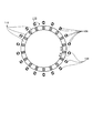
- FIG. 2 is a view for explaining the fuel injection port 126 and shows a cross section taken along line II-II in FIG.
- the fuel injection port 126 is provided on the radially outer side of the cylinder 110 with respect to the scavenging port 118. Specifically, the fuel injection port 126 is provided to face the outer surface of the cylinder 110 between the adjacent scavenging ports 118. Further, the fuel injection port 126 is positioned within the stroke direction range of the piston 112 at the scavenging port 118.
- the fuel injection ports 126 also extend in the circumferential direction of the cylinder 110 in accordance with the scavenging ports 118.
- a plurality are provided. Specifically, one fuel pipe 136 through which fuel gas is guided to each scavenging port 118 extends in the stroke direction of the piston 112.
- the fuel pipe 136 is disposed on the radially outer side of the outer surface of the cylinder 110 between the adjacent scavenging ports 118, and the flow of the active gas is not easily inhibited by the fuel pipe 136.
- the fuel injection port 126 is an opening formed on the side of the adjacent fuel pipe 136 in the fuel pipe 136.
- An annular pipe 138 is disposed on the exhaust port 114 side (the upper side in FIG. 1) of the fuel pipe 136.
- the annular pipe 138 is a pipe that annularly surrounds the radially outer side of the cylinder 110 in the circumferential direction of the cylinder 110 and communicates with the fuel pipe 136.
- Fuel gas is led to the annular pipe 138 from the fuel gas main pipe 140 in which the fuel gas is stored.
- the fuel injection port 126 sucks the injected fuel gas into the scavenging port 118 together with the active gas.
- the fuel injection port 126 may be provided at any location such as opening toward the scavenging port 118.
- a pilot injection valve 142 is provided in the cylinder head 110a.
- An appropriate amount of fuel oil is injected from the pilot injection valve 142 at a desired point in the engine cycle.
- This fuel oil is vaporized by the heat of the combustion chamber 124 formed inside the cylinder 110 surrounded by the cylinder head 110a, the cylinder liner 110b, and the piston 112. Then, the fuel oil is vaporized, spontaneously ignited and burned in a short time, and the temperature of the combustion chamber 124 is extremely increased. As a result, the fuel gas guided to the combustion chamber 124 can be reliably burned at a desired timing.
- the piston 112 reciprocates mainly by the expansion pressure due to the combustion of fuel gas.
- the fuel injection device 128 is provided upstream of the fuel pipe 136 and the annular pipe 138 in the fuel supply path 144 that communicates from the fuel gas main pipe 140 to the fuel injection port 126.
- the fuel injection device 128 opens and closes the fuel supply path 144 and controls the injection of fuel gas from the fuel injection port 126.
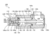
- the casing 146 of the fuel injection device 128 is constituted by two outer wall members 146a and 146b.
- the outer wall member 146a is located on the right side (cylinder 110 side) in FIGS. 3A and B with respect to the outer wall member 146b, and a gas flow path 148 through which fuel gas flows is formed.
- the first end 148a that opens to the right side in FIG. 3A communicates with the annular pipe 138, and the second end 148b that opens to the upper side in FIGS. 3A and 3B is connected to the flange member 150.
- the fuel gas main pipe 140 communicates with the other pipe.
- the outer wall member 146a is provided with a protruding portion 154 on the facing surface 152 that faces the outer wall member 146b.
- the protruding portion 154 protrudes from the facing surface 152 toward the outer wall member 146b.
- An annular recess 156 is formed on the outer periphery of the protruding portion 154 on the proximal end side.
- a through hole 158 that penetrates from the outer wall member 146b side to the gas flow path 148 is formed in the protruding portion 154.
- the first end 160a of the fuel injection valve 160 is inserted into the through hole 158 from the gas flow path 148 side.
- a valve body 160 b is formed on the second end side of the fuel injection valve 160.
- the first end 148a of the gas flow path 148 is opened and closed by the valve body 160b. That is, the fuel injection valve 160 changes between a closed state (FIG. 3A) in which the fuel supply is stopped and an open state (FIG. 3B) in which the fuel is supplied.
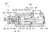
- the outer wall member 146b is provided with an opposing hole 164 having the same inner diameter as the recess 156 on the outer wall member 146a side on the opposing surface 162 of the outer wall member 146a.
- a small-diameter hole 166 having a smaller diameter than the counter hole 164 is formed on the bottom surface of the counter hole 164.
- An elastic spring 168 is disposed inside the counter hole 164, and the first end 168 a extends to the recess 156 and is fixed. The second end 168 b of the elastic spring 168 is fixed to the spring receiver 170.
- the first end 160 a of the fuel injection valve 160 passes through the spring receiver 170, and the first end 160 a protrudes from the spring receiver 170 to the inside of the small diameter hole 166.
- the spring receiver 170 is fixed to the fuel injection valve 160.
- the fuel injection valve 160 is urged to the left in the drawing by the urging force of the elastic spring 168, so that the valve body 160b is gas flow path.
- the first end 148a of 148 is closed.
- the first end 160 a of the fuel injection valve 160 is located inside the small diameter hole 166.
- the operating piston 172 is in contact with the first end 160 a of the fuel injection valve 160.
- the operating piston 172 is inserted into the small-diameter hole 166 and is slidable in the left-right direction in FIGS. 3A and 3B.
- the first end 172a of the fuel injection valve 160 contacts the first end 172a of the working piston 172, while the second end 172b located on the opposite side faces the bottom surface 166a of the small diameter hole 166.
- the hydraulic chamber 174 is formed by being surrounded by the small diameter hole 166 and the working piston 172. That is, the second end 172 b of the working piston 172 is a pressure receiving surface facing the hydraulic chamber 174.
- the outer wall member 146 b has an oil introduction hole 176 communicating with the hydraulic chamber 174, and hydraulic oil is introduced into the hydraulic chamber 174 through the oil introduction hole 176.
- hydraulic pressure in the hydraulic chamber 174 is increased by the hydraulic oil introduced into the hydraulic chamber 174 and the pressing force by the hydraulic pressure becomes larger than the urging force of the elastic spring 168, as shown in FIG.
- the first end 148a of the gas flow path 148 is opened by being pressed to the right side.
- the threshold value of the hydraulic pressure in the hydraulic chamber 174 is set by the biasing force of the elastic spring 168, and the operating piston 172 closes the fuel injection valve 160 when the pressure in the hydraulic chamber 174 is less than the threshold value. It is held at the standby position to be maintained (FIG. 3A). Then, when the pressure in the hydraulic chamber 174 becomes equal to or higher than the threshold value, the operating piston 172 moves to an operating position where the fuel injection valve 160 is opened (FIG. 3B).
- the discharge port 178 is a hole that penetrates from the small diameter hole 166 into which the operating piston 172 is inserted to the outside of the outer wall member 146b, and leaks from the hydraulic chamber 174 to the opposing hole 164 side as the operating piston 172 slides.
- the hydraulic oil is discharged out of the outer wall member 146b.
- the working piston 172 is provided with a bypass hole 180.
- the first end 180 a of the bypass hole 180 opens to the second end 172 b (pressure receiving surface) of the operating piston 172, and the second end 180 b of the bypass hole 180 slides with the inner wall of the small diameter hole 166. Open to.
- the flow of the bypass hole 180 and the hydraulic oil will be described in detail.
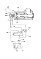
- FIG. 4 and 5 are diagrams for explaining the flow of the fuel injection device 128 and the hydraulic oil.
- FIG. 4 shows a state in which the fuel injection valve 160 is closed
- FIG. 5 shows the fuel injection valve. 160 shows an open state.
- the working oil is circulated by discharging the working oil guided from the hydraulic pump 186 to the hydraulic chamber 174 from the hydraulic chamber 174. Yes.
- the hydraulic oil warmed in the hydraulic oil tank 184 circulates, and it is possible to improve the operating accuracy of the fuel injection valve 160 by suppressing the temperature drop of the hydraulic oil in the circulation path.
- the bypass hole 180 is provided in the working piston 172, the temperature drop of the working piston 172 can be suppressed by the circulating working oil.
- the hydraulic oil tank 184 is included in the hydraulic oil circulation path, it is possible to eliminate bubbles in the hydraulic oil tank 184 by the plate member 184a.
- the switching valve 188 when the switching valve 188 is in the switching position shown in FIG. 5, the T port of the switching valve 188 is shut off, the P port and the A port are communicated, and the hydraulic chamber 174 includes the hydraulic oil inlet pipe 196 and the first The hydraulic pump 186 communicates with the supply pipe 190. Therefore, hydraulic pressure acts on the hydraulic chamber 174, and the fuel injection valve 160 is pressed and opened by the hydraulic pressure.
- the switching valve 188 guides the hydraulic oil discharged from the hydraulic pump 186 to the hydraulic chamber 174 (FIG. 5) and the hydraulic oil discharged from the hydraulic pump 186 to the discharge port 178.
- the second switching position (FIG. 4) is switched to.
- bypass hole 180 since the flow path cross section of the bypass hole 180 is sufficiently small with respect to the pressure receiving surface of the working piston 172, when the fuel injection valve 160 is changed from the closed state to the open state, the bypass hole 180 and the exhaust hole are discharged from the hydraulic chamber 174. The amount of hydraulic oil discharged through the outlet 178 is suppressed. For this reason, it is possible to suppress a decrease in responsiveness when the fuel injection valve 160 is opened.
- the bypass hole 180 guides the hydraulic oil discharged from the hydraulic pump 186 to the hydraulic chamber 174 while the operating piston 172 is held at the standby position.
- the hydraulic fluid discharged from the hydraulic pump 186 may be discharged from the hydraulic chamber 174 while the bypass hole 180 is held at the standby position of the operating piston 172.
- the discharge pressure is reduced by using the hydraulic pump 186 as a variable displacement type, and control is performed so that the hydraulic pressure in the hydraulic chamber 174 does not exceed the above threshold.
- the hydraulic fluid flows through the bypass hole 180, it is possible to suppress the temperature drop of the hydraulic fluid and improve the operational accuracy of the fuel injection valve 160.
- the casing 146 is provided with the discharge port 178, and the discharge port 178 is opposed to the second end 180b of the bypass hole 180 in a state where the operation piston 172 is held at the standby position.
- the second end 180b of the bypass hole 180 is not opposed.
- the hydraulic chamber 174 and the discharge port 178 communicate with each other so that the working oil flows through the bypass hole 180 and the working piston 172 moves to the working position. And the outlet 178 are blocked from communicating with each other.
- the fuel injection device 128 is provided in the fuel supply path 144 that communicates from the fuel gas main pipe 140 to the fuel injection port 126.
- the fuel injection device 128 may perform the fuel oil injection processing by opening and closing the pilot injection valve 142, for example.
- the fuel injection valve 160 becomes the pilot injection valve 142. That is, the fuel injected by the fuel injection device 128 may be a fuel gas or a liquid fuel.
Landscapes
- Engineering & Computer Science (AREA)
- General Engineering & Computer Science (AREA)
- Chemical & Material Sciences (AREA)
- Mechanical Engineering (AREA)
- Combustion & Propulsion (AREA)
- Physics & Mathematics (AREA)
- Fluid Mechanics (AREA)
- Analytical Chemistry (AREA)
- Chemical Kinetics & Catalysis (AREA)
- General Chemical & Material Sciences (AREA)
- Oil, Petroleum & Natural Gas (AREA)
- Fuel-Injection Apparatus (AREA)
Abstract
A fuel injection device (128) is provided with: a hydraulic pump that discharges a hydraulic oil; a casing (146) to which a hydraulic chamber (174) connected to the hydraulic pump is provided; an operating piston (172) that is slidably provided inside the casing such that if the pressure inside the hydraulic chamber is below a preset threshold value, the operating piston is held in a standby position that maintains a fuel injection valve (160) in an open state, and if the pressure inside the hydraulic chamber is greater than or equal to the threshold value, the operating piston moves to an operating position that sets the fuel injection valve to the open state; and a bypass hole (180) that is formed in the operating piston and that, while the operating piston is held in the standby position, leads, to the hydraulic chamber, the hydraulic oil discharged from the hydraulic pipe, or drains, from the hydraulic chamber, the hydraulic oil led into the hydraulic chamber from the hydraulic pump.
Description
本開示は、油圧で作動する作動ピストンを備えた油圧駆動式の燃料噴射装置、および、エンジンに関する。
本願は、2015年5月11日に日本に出願された特願2015-96718号に基づき優先権を主張し、その内容をここに援用する。 The present disclosure relates to a hydraulically driven fuel injection device including an operating piston that is hydraulically operated, and an engine.
This application claims priority based on Japanese Patent Application No. 2015-96718 filed in Japan on May 11, 2015, the contents of which are incorporated herein by reference.
エンジンには、燃焼室に燃料を供給するための燃料噴射装置が設けられる。例えば、特許文献1に記載されているように、油圧駆動式の燃料噴射装置では、作動油の油圧が油圧室に作用することでピストンが押圧される。そして、ピストンの変移によって燃料噴射弁が開閉することで、燃料の供給または停止が制御される。
The engine is provided with a fuel injection device for supplying fuel to the combustion chamber. For example, as described in Patent Document 1, in a hydraulically driven fuel injection device, a piston is pressed by the hydraulic pressure of hydraulic oil acting on a hydraulic chamber. Then, the fuel injection valve is opened and closed by the displacement of the piston, whereby the supply or stop of the fuel is controlled.
ところで、油圧駆動式の燃料噴射装置では、油圧室には作動油が充満しており、燃料噴射弁を開閉するだけでは、作動油の流動があまりないため、時間経過に伴って油圧室や油圧室近傍の油路の作動油の温度が上昇したり、逆に低下したりする。その結果、作動油の粘度が変化し、燃料噴射弁の開閉のタイミングや期間にばらつきが生じ、その作動精度が低下する場合がある。
By the way, in a hydraulically driven fuel injection device, the hydraulic chamber is filled with hydraulic oil, and there is not much flow of hydraulic oil just by opening and closing the fuel injection valve. The temperature of the hydraulic oil in the oil passage in the vicinity of the chamber increases or decreases. As a result, the viscosity of the hydraulic oil changes, and the timing and period of opening and closing of the fuel injection valve vary, which may reduce the operating accuracy.
本開示は、このような課題に鑑み、作動油の温度変化を抑制することで燃料噴射弁の作動精度を向上することが可能な燃料噴射装置、および、エンジンを提供することを目的としている。
In view of such a problem, an object of the present disclosure is to provide a fuel injection device and an engine that can improve the operation accuracy of the fuel injection valve by suppressing the temperature change of the hydraulic oil.
本開示の第一の態様は、燃料の供給を停止する閉弁状態と、燃料を供給する開弁状態とに変移する燃料噴射弁を備えた燃料噴射装置に関する。この燃料噴射装置は、作動油を吐出する油圧ポンプと、油圧ポンプに接続される油圧室が設けられたケーシングと、ケーシング内に摺動自在に設けられ、油圧室内の圧力が予め設定された閾値未満の場合に、燃料噴射弁を閉弁状態に維持する待機位置に保持され、油圧室内の圧力が閾値以上になると、燃料噴射弁を開弁状態とする作動位置に移動する作動ピストンと、作動ピストンに形成され、作動ピストンが待機位置に保持されている間、油圧ポンプから吐出された作動油を油圧室に導くか、もしくは、油圧ポンプから油圧室に導かれた作動油を油圧室から排出するバイパス孔と、を備える。
A first aspect of the present disclosure relates to a fuel injection device including a fuel injection valve that changes between a valve closing state in which fuel supply is stopped and a valve opening state in which fuel is supplied. This fuel injection device includes a hydraulic pump that discharges hydraulic oil, a casing provided with a hydraulic chamber connected to the hydraulic pump, a slidably provided in the casing, and a pressure in which the pressure in the hydraulic chamber is set in advance. If the pressure is less than the operating piston, the operating piston is held in a standby position for keeping the fuel injection valve closed, and when the pressure in the hydraulic chamber exceeds a threshold value, the operating piston moves to the operating position for opening the fuel injection valve. While the piston is formed and the working piston is held at the standby position, the hydraulic oil discharged from the hydraulic pump is guided to the hydraulic chamber, or the hydraulic oil led from the hydraulic pump to the hydraulic chamber is discharged from the hydraulic chamber. And a bypass hole.
また、本開示のエンジンは、上記の燃料噴射装置を備える。
Moreover, the engine of this indication is equipped with said fuel-injection apparatus.
本開示によれば、作動油の温度変化を抑制することで燃料噴射弁の作動精度を向上することが可能となる。
According to the present disclosure, it is possible to improve the operation accuracy of the fuel injection valve by suppressing the temperature change of the hydraulic oil.
以下に添付図面を参照しながら、本開示の好適な実施形態について詳細に説明する。本実施形態に示す寸法、材料、その他具体的な数値等は、開示の理解を容易とするための例示にすぎず、特に断る場合を除き、本開示を限定するものではない。なお、本明細書および図面において、実質的に同一の機能、構成を有する要素については、同一の符号を付することにより重複説明を省略し、また本開示に直接関係のない要素は図示を省略する。
Hereinafter, preferred embodiments of the present disclosure will be described in detail with reference to the appended drawings. The dimensions, materials, and other specific numerical values shown in this embodiment are merely examples for facilitating understanding of the disclosure, and do not limit the present disclosure unless otherwise specified. In the present specification and drawings, elements having substantially the same functions and configurations are denoted by the same reference numerals, and redundant description is omitted, and elements not directly related to the present disclosure are not illustrated. To do.
図1は、ユニフロー掃気式2サイクルエンジン100の全体構成を説明する図である。本実施形態のユニフロー掃気式2サイクルエンジン100(エンジン)は、例えば、船舶等に用いられる。具体的に、ユニフロー掃気式2サイクルエンジン100は、シリンダ110と、ピストン112と、排気ポート114と、排気弁116と、掃気ポート118と、掃気溜120と、掃気室122と、燃焼室124と、燃料噴射口126と、燃料噴射装置128と、冷却器130と、整流板132と、ドレインセパレータ134と、燃料配管136と、環状配管138と、燃料ガス主管140と、パイロット噴射弁142と、燃料供給路144とを含んで構成される。
FIG. 1 is a diagram illustrating the overall configuration of a uniflow scavenging two-cycle engine 100. The uniflow scavenging two-cycle engine 100 (engine) of the present embodiment is used for, for example, ships. Specifically, the uniflow scavenging two-cycle engine 100 includes a cylinder 110, a piston 112, an exhaust port 114, an exhaust valve 116, a scavenging port 118, a scavenging reservoir 120, a scavenging chamber 122, and a combustion chamber 124. The fuel injection port 126, the fuel injection device 128, the cooler 130, the rectifying plate 132, the drain separator 134, the fuel pipe 136, the annular pipe 138, the fuel gas main pipe 140, the pilot injection valve 142, And a fuel supply path 144.
ユニフロー掃気式2サイクルエンジン100では、ピストン112の上昇行程および下降行程の2行程の間に、排気、吸気、圧縮、燃焼、膨張が行われて、ピストン112がシリンダ110内を摺動する。ピストン112には、ピストンロッド112aの第1端が固定されている。また、ピストンロッド112aの第2端には、不図示のクロスヘッドが連結されており、クロスヘッドは、ピストン112とともに往復移動する。ピストン112の往復移動に伴いクロスヘッドが往復移動すると、その往復移動に連動して、不図示のクランクシャフトが回転する。
In the uniflow scavenging two-cycle engine 100, exhaust, intake, compression, combustion, and expansion are performed during the two strokes of the upward stroke and the downward stroke of the piston 112, and the piston 112 slides in the cylinder 110. A first end of a piston rod 112a is fixed to the piston 112. Further, a cross head (not shown) is connected to the second end of the piston rod 112 a, and the cross head reciprocates together with the piston 112. When the crosshead reciprocates as the piston 112 reciprocates, a crankshaft (not shown) rotates in conjunction with the reciprocation.
排気ポート114は、ピストン112の上死点より上方のシリンダヘッド11 0aに設けられた開口部であり、シリンダ110内で生じた燃焼後の排気ガスを排気するために開閉される。排気弁116は、排気弁駆動装置116aによって所定のタイミングで上下に移動され、排気ポート114を開閉する。排気ポート114が開いているとき、排気ポート114を介して排ガスがシリンダ110から排気される。
The exhaust port 114 is an opening provided in the cylinder head 11 </ b> O a above the top dead center of the piston 112, and is opened and closed to exhaust the exhaust gas after combustion generated in the cylinder 110. The exhaust valve 116 is moved up and down at a predetermined timing by the exhaust valve driving device 116 a to open and close the exhaust port 114. When the exhaust port 114 is open, the exhaust gas is exhausted from the cylinder 110 through the exhaust port 114.
掃気ポート118は、シリンダ110の下端側の内周面(シリンダライナ11 0bの内周面)から外局面まで貫通する孔であり、シリンダ110の全周囲に亘って、複数設けられている。そして、掃気ポート118は、ピストン112の摺動動作に応じてシリンダ110内に活性ガスを吸入する。この活性ガスは、酸素、オゾン等の酸化剤、または、その混合気(例えば空気)を含む。
The scavenging port 118 is a hole penetrating from the inner peripheral surface (the inner peripheral surface of the cylinder liner 11 </ b> 0 b) on the lower end side of the cylinder 110 to the outer surface, and a plurality of scavenging ports 118 are provided over the entire periphery of the cylinder 110. The scavenging port 118 sucks the active gas into the cylinder 110 according to the sliding motion of the piston 112. This active gas contains an oxidizing agent such as oxygen and ozone, or a mixture thereof (for example, air).
掃気溜120には、不図示のブロワーによって圧縮された活性ガス(例えば空気)が、冷却器130によって冷却されて封入されている。圧縮および冷却された活性ガスは、掃気溜120内に配置された整流板132によって整流された後、ドレインセパレータ134で水分が除去される。
In the scavenging reservoir 120, an active gas (for example, air) compressed by a blower (not shown) is cooled by a cooler 130 and enclosed. The compressed and cooled active gas is rectified by the rectifying plate 132 disposed in the scavenging reservoir 120, and then the moisture is removed by the drain separator 134.
掃気室122は、掃気溜120と連通するとともに、シリンダ110のうち、ピストン112のストローク方向の第2端側(図1中、下側)を囲んでおり、圧縮、冷却、および、水分の除去が為された活性ガスが導かれる。
The scavenging chamber 122 communicates with the scavenging reservoir 120 and surrounds the second end side (lower side in FIG. 1) of the piston 112 in the cylinder 110, and compresses, cools, and removes moisture. The active gas having been subjected to is guided.
掃気ポート118は、シリンダ110(シリンダライナ110b)のうち掃気室122内に位置する部分に設けられており、ピストン112の摺動動作に応じ、掃気室122とシリンダ110内の差圧により、掃気室122からシリンダ110内に活性ガスを吸入する。シリンダ110に吸入された活性ガスは、ピストン112によって燃焼室124に導かれる。
The scavenging port 118 is provided in a portion of the cylinder 110 (cylinder liner 110 b) located in the scavenging chamber 122, and scavenging is performed by the differential pressure between the scavenging chamber 122 and the cylinder 110 according to the sliding operation of the piston 112. Active gas is sucked into the cylinder 110 from the chamber 122. The active gas sucked into the cylinder 110 is guided to the combustion chamber 124 by the piston 112.
図2は、燃料噴射口126を説明する図であり、図1のII-II線に沿った断面を示す。図2に示すように、燃料噴射口126は、掃気ポート118よりもシリンダ110の径方向外側に設けられる。詳細には、燃料噴射口126は、隣り合う掃気ポート118の間におけるシリンダ110の外表面に対向して設けられる。また、燃料噴射口126は、掃気ポート118におけるピストン112のストローク方向の範囲内に位置している。
FIG. 2 is a view for explaining the fuel injection port 126 and shows a cross section taken along line II-II in FIG. As shown in FIG. 2, the fuel injection port 126 is provided on the radially outer side of the cylinder 110 with respect to the scavenging port 118. Specifically, the fuel injection port 126 is provided to face the outer surface of the cylinder 110 between the adjacent scavenging ports 118. Further, the fuel injection port 126 is positioned within the stroke direction range of the piston 112 at the scavenging port 118.
本実施形態では、掃気ポート118がユニフロー掃気式2サイクルエンジン100の全周囲に亘って複数設けられていることから、掃気ポート118に合わせて燃料噴射口126も、シリンダ110の周方向に亘って複数設けられている。詳細には、それぞれの掃気ポート118に対し燃料ガスが導かれる燃料配管136が1つずつ、ピストン112のストローク方向に延びて存在している。しかも、燃料配管136は、隣り合う掃気ポート118の間におけるシリンダ110の外表面の径方向外側に配置されており、燃料配管136によって活性ガスの流れが阻害され難い。また、燃料噴射口126は、燃料配管136のうち、隣り合う燃料配管136側に形成された開口となっている。
In the present embodiment, since a plurality of scavenging ports 118 are provided over the entire circumference of the uniflow scavenging two-cycle engine 100, the fuel injection ports 126 also extend in the circumferential direction of the cylinder 110 in accordance with the scavenging ports 118. A plurality are provided. Specifically, one fuel pipe 136 through which fuel gas is guided to each scavenging port 118 extends in the stroke direction of the piston 112. Moreover, the fuel pipe 136 is disposed on the radially outer side of the outer surface of the cylinder 110 between the adjacent scavenging ports 118, and the flow of the active gas is not easily inhibited by the fuel pipe 136. Further, the fuel injection port 126 is an opening formed on the side of the adjacent fuel pipe 136 in the fuel pipe 136.
燃料配管136の排気ポート114側(図1中、上側)には、環状配管138が配置されている。環状配管138は、シリンダ110の径方向外側をシリンダ110の周方向に環状に囲む配管であって、燃料配管136と連通している。環状配管138には、燃料ガスが貯留された燃料ガス主管140から燃料ガスが導かれる。
An annular pipe 138 is disposed on the exhaust port 114 side (the upper side in FIG. 1) of the fuel pipe 136. The annular pipe 138 is a pipe that annularly surrounds the radially outer side of the cylinder 110 in the circumferential direction of the cylinder 110 and communicates with the fuel pipe 136. Fuel gas is led to the annular pipe 138 from the fuel gas main pipe 140 in which the fuel gas is stored.
燃料噴射口126は、燃料ガス主管140から環状配管138を介して供給された燃料ガスを、掃気ポート118に吸入される活性ガスに噴射する。その結果、燃料ガスは、図2中、破線の矢印で示すように、活性ガスの流れに合流して活性ガスとともに掃気ポート118からシリンダ110内に吸入され、燃焼室124に導かれる。
The fuel injection port 126 injects the fuel gas supplied from the fuel gas main pipe 140 through the annular pipe 138 into the active gas sucked into the scavenging port 118. As a result, as shown by the broken arrow in FIG. 2, the fuel gas merges with the flow of the active gas, is sucked into the cylinder 110 from the scavenging port 118 together with the active gas, and is guided to the combustion chamber 124.
図2の例では、燃料噴射口126が、隣り合う燃料配管136側に向けて開口される場合について説明したが、燃料噴射口126は、噴射された燃料ガスが活性ガスとともに掃気ポート118に吸入されればよく、例えば、掃気ポート118側に向けて開口させる等、燃料噴射口126をいずれの箇所に設けてもよい。
In the example of FIG. 2, the case where the fuel injection port 126 is opened toward the adjacent fuel pipe 136 side has been described. However, the fuel injection port 126 sucks the injected fuel gas into the scavenging port 118 together with the active gas. For example, the fuel injection port 126 may be provided at any location such as opening toward the scavenging port 118.
また、図2の例では、燃料配管136と掃気ポート118が同数、配置されている場合について説明したが、燃料配管136と掃気ポート118の配置数が異なっていてもよく、例えば、2つの掃気ポート118ごとに1つの燃料配管136が設けられていてもよい。
In the example of FIG. 2, the case where the same number of the fuel pipes 136 and the scavenging ports 118 are arranged has been described. However, the number of the fuel pipes 136 and the scavenging ports 118 may be different. One fuel pipe 136 may be provided for each port 118.
また、図1に示すように、シリンダヘッド110aには、パイロット噴射弁142が設けられる。そして、エンジンサイクルにおける所望の時点で、適量の燃料油がパイロット噴射弁142から噴射される。この燃料油は、シリンダヘッド110aと、シリンダライナ110bと、ピストン112とに囲まれてシリンダ110の内部に形成された燃焼室124の熱で気化する。そして、燃料油が気化して自然着火し僅かな時間で燃焼して、燃焼室124の温度を極めて高くする。その結果、燃焼室124に導かれた燃料ガスを、所望のタイミングで確実に燃焼させることができる。ピストン112は、主に燃料ガスの燃焼による膨張圧によって往復移動する。
Further, as shown in FIG. 1, a pilot injection valve 142 is provided in the cylinder head 110a. An appropriate amount of fuel oil is injected from the pilot injection valve 142 at a desired point in the engine cycle. This fuel oil is vaporized by the heat of the combustion chamber 124 formed inside the cylinder 110 surrounded by the cylinder head 110a, the cylinder liner 110b, and the piston 112. Then, the fuel oil is vaporized, spontaneously ignited and burned in a short time, and the temperature of the combustion chamber 124 is extremely increased. As a result, the fuel gas guided to the combustion chamber 124 can be reliably burned at a desired timing. The piston 112 reciprocates mainly by the expansion pressure due to the combustion of fuel gas.
ここで、燃料ガスは、例えば、LNG(液化天然ガス)をガス化して生成される。また、燃料ガスには、LNGに限らず、例えば、LPG(液化石油ガス)、軽油、重油等をガス化して適用することもできる。
Here, the fuel gas is generated, for example, by gasifying LNG (liquefied natural gas). Further, the fuel gas is not limited to LNG, and for example, LPG (liquefied petroleum gas), light oil, heavy oil, etc. can be gasified and applied.
燃料噴射装置128は、燃料ガス主管140から燃料噴射口126まで連通する燃料供給路144のうち、燃料配管136や環状配管138よりも上流側に設けられる。そして、燃料噴射装置128は、燃料供給路144を開閉し、燃料噴射口126からの燃料ガスの噴射を制御する。
The fuel injection device 128 is provided upstream of the fuel pipe 136 and the annular pipe 138 in the fuel supply path 144 that communicates from the fuel gas main pipe 140 to the fuel injection port 126. The fuel injection device 128 opens and closes the fuel supply path 144 and controls the injection of fuel gas from the fuel injection port 126.
図3AおよびBは、燃料噴射装置128を説明する図であり、図1中、シリンダ110の左側に配された燃料噴射装置128の概略断面を示す。図1中、シリンダ110の右側に配された燃料噴射装置128については、構造が実質的に同等であるため詳細な説明を省略する。
3A and 3B are views for explaining the fuel injection device 128, and show a schematic cross section of the fuel injection device 128 arranged on the left side of the cylinder 110 in FIG. In FIG. 1, the fuel injection device 128 disposed on the right side of the cylinder 110 is substantially the same in structure, and detailed description thereof is omitted.
図3AおよびBに示すように、燃料噴射装置128のケーシング146は、2つの外壁部材146a、146bによって構成されている。外壁部材146aは、外壁部材146bよりも、図3AおよびB中、右側(シリンダ110側)に位置しており、内部に燃料ガスが流通するガス流路148が形成される。
As shown in FIGS. 3A and 3B, the casing 146 of the fuel injection device 128 is constituted by two outer wall members 146a and 146b. The outer wall member 146a is located on the right side (cylinder 110 side) in FIGS. 3A and B with respect to the outer wall member 146b, and a gas flow path 148 through which fuel gas flows is formed.
ガス流路148のうち、図3AおよびB中、右側に開口する第1端148aは環状配管138と連通し、図3AおよびB中、上側に開口する第2端148bはフランジ部材150に連結された配管を介して燃料ガス主管140と連通する。
3A and B, the first end 148a that opens to the right side in FIG. 3A communicates with the annular pipe 138, and the second end 148b that opens to the upper side in FIGS. 3A and 3B is connected to the flange member 150. The fuel gas main pipe 140 communicates with the other pipe.
また、外壁部材146aには、外壁部材146bに対向する対向面152に突出部154が設けられている。突出部154は、対向面152から外壁部材146b側に突出している。突出部154の基端側の外周には、環状の窪み156が形成されている。
Further, the outer wall member 146a is provided with a protruding portion 154 on the facing surface 152 that faces the outer wall member 146b. The protruding portion 154 protrudes from the facing surface 152 toward the outer wall member 146b. An annular recess 156 is formed on the outer periphery of the protruding portion 154 on the proximal end side.
そして、突出部154には、外壁部材146b側からガス流路148まで貫通する貫通孔158が形成されている。貫通孔158には、ガス流路148側から燃料噴射弁160の第1端160aが挿通される。燃料噴射弁160の第2端側には弁体160bが形成されている。弁体160bによってガス流路148の第1端148aが開閉される。すなわち、燃料噴射弁160は、燃料の供給を停止する閉弁状態(図3A)と、燃料を供給する開弁状態(図3B)とに変移する。
A through hole 158 that penetrates from the outer wall member 146b side to the gas flow path 148 is formed in the protruding portion 154. The first end 160a of the fuel injection valve 160 is inserted into the through hole 158 from the gas flow path 148 side. A valve body 160 b is formed on the second end side of the fuel injection valve 160. The first end 148a of the gas flow path 148 is opened and closed by the valve body 160b. That is, the fuel injection valve 160 changes between a closed state (FIG. 3A) in which the fuel supply is stopped and an open state (FIG. 3B) in which the fuel is supplied.
外壁部材146bには、外壁部材146aとの対向面162に、外壁部材146a側の窪み156と同じ内径の対向孔164が設けられている。対向孔164の底面には、対向孔164よりも小径な小径孔166が形成されている。そして、対向孔164の内部には弾性バネ168が配置され、その第1端168aが窪み156まで延びて固定される。また、弾性バネ168の第2端168bは、スプリング受け170に固定されている。
The outer wall member 146b is provided with an opposing hole 164 having the same inner diameter as the recess 156 on the outer wall member 146a side on the opposing surface 162 of the outer wall member 146a. A small-diameter hole 166 having a smaller diameter than the counter hole 164 is formed on the bottom surface of the counter hole 164. An elastic spring 168 is disposed inside the counter hole 164, and the first end 168 a extends to the recess 156 and is fixed. The second end 168 b of the elastic spring 168 is fixed to the spring receiver 170.
燃料噴射弁160の第1端160aは、スプリング受け170を貫通し、スプリング受け170から第1端160aが、小径孔166の内部まで突出している。スプリング受け170は、燃料噴射弁160に固定されており、図3Aでは、弾性バネ168の付勢力によって燃料噴射弁160が、図中、左側に付勢されることで弁体160bがガス流路148の第1端148aを閉じている。
The first end 160 a of the fuel injection valve 160 passes through the spring receiver 170, and the first end 160 a protrudes from the spring receiver 170 to the inside of the small diameter hole 166. The spring receiver 170 is fixed to the fuel injection valve 160. In FIG. 3A, the fuel injection valve 160 is urged to the left in the drawing by the urging force of the elastic spring 168, so that the valve body 160b is gas flow path. The first end 148a of 148 is closed.
上記のように、小径孔166の内部には、燃料噴射弁160の第1端160aが位置している。また、燃料噴射弁160の第1端160aには、作動ピストン172が接触している。作動ピストン172は、小径孔166に挿入されるとともに、小径孔166内を、図3AおよびB中、左右方向に摺動自在なサイズとなっている。また、作動ピストン172の第1端172aには燃料噴射弁160の第1端160aが接触するのに対し、反対側に位置する第2端172bは、小径孔166の底面166aに対向する。
As described above, the first end 160 a of the fuel injection valve 160 is located inside the small diameter hole 166. In addition, the operating piston 172 is in contact with the first end 160 a of the fuel injection valve 160. The operating piston 172 is inserted into the small-diameter hole 166 and is slidable in the left-right direction in FIGS. 3A and 3B. The first end 172a of the fuel injection valve 160 contacts the first end 172a of the working piston 172, while the second end 172b located on the opposite side faces the bottom surface 166a of the small diameter hole 166.
油圧室174は、小径孔166と作動ピストン172とで囲まれて形成される。すなわち、作動ピストン172の第2端172bは、油圧室174に対向する受圧面となっている。
The hydraulic chamber 174 is formed by being surrounded by the small diameter hole 166 and the working piston 172. That is, the second end 172 b of the working piston 172 is a pressure receiving surface facing the hydraulic chamber 174.
また、外壁部材146bには、油圧室174に連通する導油孔176が形成されており、導油孔176を介して油圧室174に作動油が導入される。油圧室174に導入された作動油によって油圧室174内の油圧が昇圧され、弾性バネ168の付勢力よりも油圧による押圧力が大きくなると、図3Bに示すように、燃料噴射弁160が、図中、右側に押圧されて、ガス流路148の第1端148aが開く。
The outer wall member 146 b has an oil introduction hole 176 communicating with the hydraulic chamber 174, and hydraulic oil is introduced into the hydraulic chamber 174 through the oil introduction hole 176. When the hydraulic pressure in the hydraulic chamber 174 is increased by the hydraulic oil introduced into the hydraulic chamber 174 and the pressing force by the hydraulic pressure becomes larger than the urging force of the elastic spring 168, as shown in FIG. The first end 148a of the gas flow path 148 is opened by being pressed to the right side.
逆に、油圧室174内の油圧が降下し、弾性バネ168の付勢力より油圧による押圧力が小さくなると、図3Aに示すように、燃料噴射弁160が、図中、左側に押圧されて、ガス流路148の第1端148aが閉じる。
Conversely, when the hydraulic pressure in the hydraulic chamber 174 drops and the pressing force by the hydraulic pressure becomes smaller than the urging force of the elastic spring 168, as shown in FIG. 3A, the fuel injection valve 160 is pressed to the left in the figure, The first end 148a of the gas flow path 148 is closed.
すなわち、弾性バネ168の付勢力によって油圧室174内の油圧の閾値が設定されており、作動ピストン172は、油圧室174内の圧力が閾値未満の場合に、燃料噴射弁160を閉弁状態に維持する待機位置に保持される(図3A)。そして、作動ピストン172は、油圧室174内の圧力が閾値以上になると、燃料噴射弁160を開弁状態とする作動位置に移動する(図3B)。
That is, the threshold value of the hydraulic pressure in the hydraulic chamber 174 is set by the biasing force of the elastic spring 168, and the operating piston 172 closes the fuel injection valve 160 when the pressure in the hydraulic chamber 174 is less than the threshold value. It is held at the standby position to be maintained (FIG. 3A). Then, when the pressure in the hydraulic chamber 174 becomes equal to or higher than the threshold value, the operating piston 172 moves to an operating position where the fuel injection valve 160 is opened (FIG. 3B).
排出口178は、作動ピストン172が挿入された小径孔166から、外壁部材146bの外部まで貫通する孔であって、作動ピストン172の摺動に伴って油圧室174から対向孔164側に漏出する作動油を外壁部材146b外に排出する。
The discharge port 178 is a hole that penetrates from the small diameter hole 166 into which the operating piston 172 is inserted to the outside of the outer wall member 146b, and leaks from the hydraulic chamber 174 to the opposing hole 164 side as the operating piston 172 slides. The hydraulic oil is discharged out of the outer wall member 146b.
また、作動ピストン172にはバイパス孔180が設けられる。バイパス孔180の第1端180aは、作動ピストン172の第2端172b(受圧面)に開口するとともに、バイパス孔180の第2端180bは、小径孔166の内壁と摺動する摺動面172cに開口する。以下、バイパス孔180および作動油の流れについて詳述する。
The working piston 172 is provided with a bypass hole 180. The first end 180 a of the bypass hole 180 opens to the second end 172 b (pressure receiving surface) of the operating piston 172, and the second end 180 b of the bypass hole 180 slides with the inner wall of the small diameter hole 166. Open to. Hereinafter, the flow of the bypass hole 180 and the hydraulic oil will be described in detail.
図4および図5は、燃料噴射装置128および作動油の流れを説明するための図であり、図4には、燃料噴射弁160が閉じている状態を示し、図5には、燃料噴射弁160が開いている状態を示す。
4 and 5 are diagrams for explaining the flow of the fuel injection device 128 and the hydraulic oil. FIG. 4 shows a state in which the fuel injection valve 160 is closed, and FIG. 5 shows the fuel injection valve. 160 shows an open state.
図4および図5に示すように、作動油タンク184には、作動油を吐出する油圧ポンプ186が接続されている。そして、油圧ポンプ186の吐出口には第1供給管190が接続されており、この第1供給管190に、2位置3ポートを備える切換バルブ188のPポートが接続されている。第1供給管190からは、排出口178まで延びる循環用管192が分岐しており、循環用管192には絞り弁194が設けられている。
As shown in FIGS. 4 and 5, the hydraulic oil tank 184 is connected to a hydraulic pump 186 that discharges the hydraulic oil. A first supply pipe 190 is connected to the discharge port of the hydraulic pump 186, and a P port of a switching valve 188 having two positions and three ports is connected to the first supply pipe 190. A circulation pipe 192 extending to the discharge port 178 branches from the first supply pipe 190, and a throttle valve 194 is provided in the circulation pipe 192.
また、切換バルブ188のAポートと、導油孔176は、作動油入口管196によって連通され、切換バルブ188のTポートと、作動油タンク184は、戻り管198によって連通される。作動油タンク184内には、気泡除去用の板部材184aが複数配置されるとともに、不図示のヒータによって作動油タンク184内の作動油が温められている。
Further, the A port of the switching valve 188 and the oil introduction hole 176 are communicated by a hydraulic oil inlet pipe 196, and the T port of the switching valve 188 and the hydraulic oil tank 184 are communicated by a return pipe 198. A plurality of plate members 184a for removing bubbles are arranged in the hydraulic oil tank 184, and the hydraulic oil in the hydraulic oil tank 184 is warmed by a heater (not shown).
切換バルブ188が図4に示す切換位置にあるとき、切換バルブ188のPポートが遮断され、AポートとTポートが連通されており、油圧室174は、作動油入口管196、戻り管198を介して作動油タンク184と連通する。そのため、油圧室174に油圧が作用せず、燃料噴射弁160は弾性バネ168の付勢力によって閉じられている。
When the switching valve 188 is in the switching position shown in FIG. 4, the P port of the switching valve 188 is shut off and the A port and T port are in communication, and the hydraulic chamber 174 includes a hydraulic oil inlet pipe 196 and a return pipe 198. Via the hydraulic oil tank 184. Therefore, no hydraulic pressure acts on the hydraulic chamber 174, and the fuel injection valve 160 is closed by the biasing force of the elastic spring 168.
このとき、油圧ポンプ186で昇圧された作動油は、絞り弁194を通って排出口178に流入する。排出口178は、作動ピストン172が図4に示す待機位置に保持された状態で、バイパス孔180の第2端180bに対向しており、作動油は、排出口178からバイパス孔180を介して油圧室174に流入する。
At this time, the hydraulic oil whose pressure has been increased by the hydraulic pump 186 flows into the discharge port 178 through the throttle valve 194. The discharge port 178 is opposed to the second end 180b of the bypass hole 180 in a state where the operating piston 172 is held at the standby position shown in FIG. 4, and the hydraulic oil passes through the bypass port 180 from the discharge port 178. It flows into the hydraulic chamber 174.
そして、油圧室174に流入した作動油は、導油孔176および作動油入口管196を介して切換バルブ188のAポートに流れる。切換バルブ188のAポートは、Tポートと連通しており、作動油は、Aポート、Tポート、戻り管198を介して作動油タンク184に環流する。
The hydraulic oil that has flowed into the hydraulic chamber 174 flows to the A port of the switching valve 188 via the oil guide hole 176 and the hydraulic oil inlet pipe 196. The A port of the switching valve 188 communicates with the T port, and the hydraulic oil circulates to the hydraulic oil tank 184 via the A port, the T port, and the return pipe 198.
このように、作動ピストン172が待機位置に保持された状態では、油圧ポンプ186から油圧室174に導かれた作動油を導油孔176が油圧室174から排出することで作動油を循環させている。これにより、作動油タンク184で温められた作動油が循環することとなり、循環経路の作動油の温度低下を抑制して燃料噴射弁160の作動精度を向上することが可能となる。また、バイパス孔180が作動ピストン172に設けられているため、循環する作動油によって作動ピストン172の温度低下も抑制可能となる。さらに、作動油の循環経路に作動油タンク184が含まれることから、作動油タンク184内において板部材184aによる気泡の消泡を図ることが可能となる。
Thus, in a state where the working piston 172 is held at the standby position, the working oil is circulated by discharging the working oil guided from the hydraulic pump 186 to the hydraulic chamber 174 from the hydraulic chamber 174. Yes. As a result, the hydraulic oil warmed in the hydraulic oil tank 184 circulates, and it is possible to improve the operating accuracy of the fuel injection valve 160 by suppressing the temperature drop of the hydraulic oil in the circulation path. Moreover, since the bypass hole 180 is provided in the working piston 172, the temperature drop of the working piston 172 can be suppressed by the circulating working oil. Furthermore, since the hydraulic oil tank 184 is included in the hydraulic oil circulation path, it is possible to eliminate bubbles in the hydraulic oil tank 184 by the plate member 184a.
一方、切換バルブ188が図5に示す切換位置にあるとき、切換バルブ188のTポートが遮断され、PポートとAポートが連通されており、油圧室174は、作動油入口管196および第1供給管190を介して油圧ポンプ186と連通する。そのため、油圧室174に油圧が作用し、燃料噴射弁160は油圧によって押圧されて開く。
On the other hand, when the switching valve 188 is in the switching position shown in FIG. 5, the T port of the switching valve 188 is shut off, the P port and the A port are communicated, and the hydraulic chamber 174 includes the hydraulic oil inlet pipe 196 and the first The hydraulic pump 186 communicates with the supply pipe 190. Therefore, hydraulic pressure acts on the hydraulic chamber 174, and the fuel injection valve 160 is pressed and opened by the hydraulic pressure.
このように、切換バルブ188は、油圧ポンプ186から吐出された作動油を油圧室174に導く第1切換位置(図5)、および、油圧ポンプ186から吐出された作動油を排出口178に導く第2切換位置(図4) に切り換えられる。
As described above, the switching valve 188 guides the hydraulic oil discharged from the hydraulic pump 186 to the hydraulic chamber 174 (FIG. 5) and the hydraulic oil discharged from the hydraulic pump 186 to the discharge port 178. The second switching position (FIG. 4) is switched to.
作動ピストン172が図5に示す作動位置に移動すると、排出口178は、バイパス孔180の第2端180bと非対向となり、バイパス孔180の第2端180bは、小径孔166の内壁によって閉塞される。その結果、油圧ポンプ186で昇圧された作動油は、循環用管192側に流入するが、絞り弁194によって作動油流量が制限される ことから、作動ピストン172の動作には影響しない。
When the operating piston 172 moves to the operating position shown in FIG. 5, the discharge port 178 is not opposed to the second end 180 b of the bypass hole 180, and the second end 180 b of the bypass hole 180 is blocked by the inner wall of the small diameter hole 166. The As a result, the hydraulic oil whose pressure has been increased by the hydraulic pump 186 flows into the circulation pipe 192 side, but since the flow rate of the hydraulic oil is limited by the throttle valve 194, the operation of the operating piston 172 is not affected.
また、バイパス孔180の流路断面は、作動ピストン172の受圧面に対して十分に小さいため、燃料噴射弁160が閉じた状態から開いた状態になるとき、油圧室174からバイパス孔180および排出口178を介して排出される作動油の排出量が抑制される。そのため、燃料噴射弁160を開くときの応答性の低下を抑制することが可能となる。
Further, since the flow path cross section of the bypass hole 180 is sufficiently small with respect to the pressure receiving surface of the working piston 172, when the fuel injection valve 160 is changed from the closed state to the open state, the bypass hole 180 and the exhaust hole are discharged from the hydraulic chamber 174. The amount of hydraulic oil discharged through the outlet 178 is suppressed. For this reason, it is possible to suppress a decrease in responsiveness when the fuel injection valve 160 is opened.
上述した実施形態では、バイパス孔180が、作動ピストン172が待機位置に保持されている間、油圧ポンプ186から吐出された作動油を油圧室174に導いている。しかし、バイパス孔180が、作動ピストン172が待機位置に保持されている間、油圧ポンプ186から吐出された作動油を、油圧室174から排出してもよい。この場合、例えば、油圧ポンプ186を可変容量型として吐出圧を下げ、油圧室174の油圧が上記の閾値以上とならないように制御する。いずれにしても、バイパス孔180を介して作動油が流動すれば、作動油の温度低下を抑制して燃料噴射弁160の作動精度を向上することが可能となる。
In the embodiment described above, the bypass hole 180 guides the hydraulic oil discharged from the hydraulic pump 186 to the hydraulic chamber 174 while the operating piston 172 is held at the standby position. However, the hydraulic fluid discharged from the hydraulic pump 186 may be discharged from the hydraulic chamber 174 while the bypass hole 180 is held at the standby position of the operating piston 172. In this case, for example, the discharge pressure is reduced by using the hydraulic pump 186 as a variable displacement type, and control is performed so that the hydraulic pressure in the hydraulic chamber 174 does not exceed the above threshold. In any case, if the hydraulic fluid flows through the bypass hole 180, it is possible to suppress the temperature drop of the hydraulic fluid and improve the operational accuracy of the fuel injection valve 160.
また、上述した実施形態では、ケーシング146に排出口178が設けられ、排出口178は、作動ピストン172が待機位置に保持された状態で、バイパス孔180の第2端180bに対向し、作動ピストン172が作動位置に移動すると、バイパス孔180の第2端180bと非対向となる。そして、作動ピストン172が待機位置に保持されている間、油圧室174と排出口178とが連通してバイパス孔180を作動油が流通し、作動ピストン172が作動位置に移動すると、油圧室174と排出口178との連通が遮断される。しかし、排出口178は必須の構成ではなく、排出口178とバイパス孔180が対向するか否かによって、油圧室174と排出口178との連通状態が変わる構成でなくてもよい。ただし、排出口178とバイパス孔180を上記の位置関係とすることで、作動ピストン172が待機位置から作動位置側に動けば、バイパス孔180の第2端180bが閉塞され、燃料噴射弁160を開くときの応答性の低下を抑制することが可能となる。また、上述した実施形態では、作動ピストン172が待機位置から作動位置側に僅かに動けば、作動位置に到る前に、バイパス孔180の第2端180bが閉塞されるため、燃料噴射弁160を開くときの応答性の低下を一層抑制することができる。
In the above-described embodiment, the casing 146 is provided with the discharge port 178, and the discharge port 178 is opposed to the second end 180b of the bypass hole 180 in a state where the operation piston 172 is held at the standby position. When 172 moves to the operating position, the second end 180b of the bypass hole 180 is not opposed. When the working piston 172 is held at the standby position, the hydraulic chamber 174 and the discharge port 178 communicate with each other so that the working oil flows through the bypass hole 180 and the working piston 172 moves to the working position. And the outlet 178 are blocked from communicating with each other. However, the discharge port 178 is not an essential configuration, and the communication state between the hydraulic chamber 174 and the discharge port 178 may not be changed depending on whether the discharge port 178 and the bypass hole 180 face each other. However, by setting the discharge port 178 and the bypass hole 180 in the above positional relationship, if the operating piston 172 moves from the standby position to the operating position side, the second end 180b of the bypass hole 180 is closed, and the fuel injection valve 160 is blocked. It is possible to suppress a decrease in responsiveness when opening. In the above-described embodiment, if the operating piston 172 slightly moves from the standby position to the operating position side, the second end 180b of the bypass hole 180 is closed before reaching the operating position. It is possible to further suppress a decrease in responsiveness when opening.
また、上述した実施形態では、第1切換位置、および、第2切換位置に切り換えられる切換バルブ188を備えている。しかし、上記のように、油圧ポンプ186を可変容量型として吐出圧を下げ、油圧室174の油圧が閾値以上とならないように制御すれば、切換バルブ188は必須の構成ではない。ただし、切換バルブ188を設けることで、油圧ポンプ186を可変容量型とせずに一定の出力で動作させていても、燃料噴射弁160の開閉を切り換えることが可能となる。
In the above-described embodiment, the switching valve 188 that is switched to the first switching position and the second switching position is provided. However, as described above, the switching valve 188 is not indispensable if the hydraulic pump 186 is of a variable displacement type and the discharge pressure is reduced so that the hydraulic pressure in the hydraulic chamber 174 does not exceed the threshold value. However, by providing the switching valve 188, it is possible to switch the opening and closing of the fuel injection valve 160 even when the hydraulic pump 186 is not operated as a variable displacement type and is operated at a constant output.
また、上述した実施形態では、作動油を作動油タンク184に循環させて昇温することで作動油の温度低下を抑制している。しかし、例えば、作動油タンク184の作動油を冷却する冷却器を設け、作動油を作動油タンク184に循環させて冷却することで作動油の温度上昇を抑制してもよい。
Further, in the above-described embodiment, the hydraulic oil is circulated through the hydraulic oil tank 184 and the temperature is raised to suppress the temperature drop of the hydraulic oil. However, for example, a cooler that cools the hydraulic oil in the hydraulic oil tank 184 may be provided, and the hydraulic oil may be circulated through the hydraulic oil tank 184 to be cooled, thereby suppressing the temperature rise of the hydraulic oil.
また、上述した実施形態では、燃料噴射装置128が、燃料ガス主管140から燃料噴射口126まで連通する燃料供給路144に設けられている。しかし、燃料噴射装置128が、例えば、パイロット噴射弁142を開閉して燃料油の噴射処理を遂行してもよい。この場合、燃料噴射弁160は、パイロット噴射弁142となる。すなわち、燃料噴射装置128が噴射する燃料は、燃料ガスであっても液体燃料であってもよい。
In the above-described embodiment, the fuel injection device 128 is provided in the fuel supply path 144 that communicates from the fuel gas main pipe 140 to the fuel injection port 126. However, the fuel injection device 128 may perform the fuel oil injection processing by opening and closing the pilot injection valve 142, for example. In this case, the fuel injection valve 160 becomes the pilot injection valve 142. That is, the fuel injected by the fuel injection device 128 may be a fuel gas or a liquid fuel.
以上、添付図面を参照しながら本開示の好適な実施形態について説明したが、本開示は上記実施形態に限定されないことは言うまでもない。当業者であれば、請求の範囲に記載された範疇において、各種の変更例または修正例に想到し得ることは明らかであり、それらについても当然に本開示の技術的範囲に属するものと了解される。
As mentioned above, although preferred embodiment of this indication was described referring an accompanying drawing, it cannot be overemphasized that this indication is not limited to the above-mentioned embodiment. It will be apparent to those skilled in the art that various changes and modifications can be made within the scope of the claims, and these are naturally within the technical scope of the present disclosure. The
本開示は、油圧で作動する作動ピストンを備えた油圧駆動式の燃料噴射装置、および、エンジンに利用することができる。
The present disclosure can be used for a hydraulically driven fuel injection device including an operation piston that is hydraulically operated, and an engine.
100 ユニフロー掃気式2サイクルエンジン(エンジン)
128 燃料噴射装置
146 ケーシング
160 燃料噴射弁
172 作動ピストン
172b 第2端(受圧面)
172c 摺動面(受圧面と異なる面)
174 油圧室
178 排出口
180 バイパス孔
180a 第1端
180b 第2端
186 油圧ポンプ
188 切換バルブ 100 Uniflow scavenging two-cycle engine (engine)
128Fuel injection device 146 Casing 160 Fuel injection valve 172 Operating piston 172b Second end (pressure receiving surface)
172c Sliding surface (surface different from pressure receiving surface)
174Hydraulic chamber 178 Discharge port 180 Bypass hole 180a First end 180b Second end 186 Hydraulic pump 188 Switching valve
128 燃料噴射装置
146 ケーシング
160 燃料噴射弁
172 作動ピストン
172b 第2端(受圧面)
172c 摺動面(受圧面と異なる面)
174 油圧室
178 排出口
180 バイパス孔
180a 第1端
180b 第2端
186 油圧ポンプ
188 切換バルブ 100 Uniflow scavenging two-cycle engine (engine)
128
172c Sliding surface (surface different from pressure receiving surface)
174
Claims (4)
- 燃料の供給を停止する閉弁状態と、燃料を供給する開弁状態とに変移する燃料噴射弁を備えた燃料噴射装置であって、
作動油を吐出する油圧ポンプと、
前記油圧ポンプに接続される油圧室が設けられたケーシングと、
前記ケーシング内に摺動自在に設けられ、前記油圧室内の圧力が予め設定された閾値未満の場合に、前記燃料噴射弁を閉弁状態に維持する待機位置に保持され、前記油圧室内の圧力が闘値以上になると、前記燃料噴射弁を開弁状態とする作動位置に移動する作動ピストンと、
前記作動ピストンに形成され、前記作動ピストンが前記待機位置に保持されている間、前記油圧ポンプから吐出された作動油を前記油圧室に導くか、もしくは、前記油圧ポンプから前記油圧室に導かれた作動油を前記油圧室から排出するバイパス孔と、
を備える燃料噴射装置。 A fuel injection device including a fuel injection valve that changes between a closed state in which fuel supply is stopped and an open state in which fuel is supplied,
A hydraulic pump that discharges hydraulic oil;
A casing provided with a hydraulic chamber connected to the hydraulic pump;
When slidably provided in the casing and the pressure in the hydraulic chamber is less than a preset threshold, the fuel injection valve is held at a standby position to keep the valve closed, and the pressure in the hydraulic chamber is An operating piston that moves to an operating position that opens the fuel injection valve when the threshold value is exceeded,
The hydraulic oil discharged from the hydraulic pump is guided to the hydraulic chamber or formed from the hydraulic pump to the hydraulic chamber while the hydraulic piston is formed in the operating piston and held at the standby position. A bypass hole for discharging the hydraulic fluid from the hydraulic chamber;
A fuel injection device comprising: - 前記作動ピストンが、前記油圧室に面する受圧面を有するとともに、前記バイパス孔の第1端が前記受圧面に開口し、前記バイパス孔の第2端が前記受圧面と異なる面に開口し、
前記ケーシングには、前記作動ピストンが前記待機位置に保持された状態で、前記バイパス孔の第2端に対向し、前記作動ピストンが前記作動位置に移動すると、前記バイパス孔の第2端と非対向となる排出口が設けられ、
前記作動ピストンが前記待機位置に保持されている間、前記油圧室と前記排出口とが連通して前記バイパス孔を作動油が流通し、前記作動ピストンが前記作動位置に移動すると、前記油圧室と前記排出口との連通が遮断される請求項1に記載の燃料噴射装置。 The operating piston has a pressure receiving surface facing the hydraulic chamber, the first end of the bypass hole opens to the pressure receiving surface, and the second end of the bypass hole opens to a surface different from the pressure receiving surface,
The casing faces the second end of the bypass hole in a state where the operating piston is held at the standby position. When the operating piston moves to the operating position, the casing is not connected to the second end of the bypass hole. There is an opposite outlet,
While the working piston is held at the standby position, the hydraulic chamber and the discharge port communicate with each other, the working oil flows through the bypass hole, and the working piston moves to the working position. The fuel injection device according to claim 1, wherein communication between the exhaust port and the exhaust port is blocked. - 前記油圧ポンプから吐出された作動油を前記油圧室に導く第1切換位置、および、前記油圧ポンプから吐出された作動油を前記排出口に導く第2切換位置に切り換えられる切換バルプを備える請求項2に記載の燃料噴射装置。 A switching valve that is switched to a first switching position that guides hydraulic oil discharged from the hydraulic pump to the hydraulic chamber and a second switching position that guides hydraulic oil discharged from the hydraulic pump to the discharge port. 2. The fuel injection device according to 2.
- 前記請求項1から3のいずれか1項に記載の燃料噴射装置を備えるエンジン。 An engine comprising the fuel injection device according to any one of claims 1 to 3.
Priority Applications (4)
| Application Number | Priority Date | Filing Date | Title |
|---|---|---|---|
| EP16792724.3A EP3296557B1 (en) | 2015-05-11 | 2016-05-11 | Fuel injection device and engine |
| KR1020177017269A KR101905803B1 (en) | 2015-05-11 | 2016-05-11 | Fuel injection device and engine |
| CN201680022626.XA CN107429646B (en) | 2015-05-11 | 2016-05-11 | Fuel injection device and engine |
| DK16792724.3T DK3296557T3 (en) | 2015-05-11 | 2016-05-11 | FUEL INJECTION DEVICE AND ENGINE |
Applications Claiming Priority (2)
| Application Number | Priority Date | Filing Date | Title |
|---|---|---|---|
| JP2015096718A JP6524788B2 (en) | 2015-05-11 | 2015-05-11 | Fuel injection device and engine |
| JP2015-096718 | 2015-05-11 |
Publications (1)
| Publication Number | Publication Date |
|---|---|
| WO2016181999A1 true WO2016181999A1 (en) | 2016-11-17 |
Family
ID=57248891
Family Applications (1)
| Application Number | Title | Priority Date | Filing Date |
|---|---|---|---|
| PCT/JP2016/064043 WO2016181999A1 (en) | 2015-05-11 | 2016-05-11 | Fuel injection device and engine |
Country Status (6)
| Country | Link |
|---|---|
| EP (1) | EP3296557B1 (en) |
| JP (1) | JP6524788B2 (en) |
| KR (1) | KR101905803B1 (en) |
| CN (1) | CN107429646B (en) |
| DK (1) | DK3296557T3 (en) |
| WO (1) | WO2016181999A1 (en) |
Families Citing this family (3)
| Publication number | Priority date | Publication date | Assignee | Title |
|---|---|---|---|---|
| CN110284977A (en) * | 2019-06-12 | 2019-09-27 | 拓尔普科技有限公司 | A kind of high low grade Full-automatic cutting changes fuel supply method |
| DE102021000617A1 (en) * | 2021-02-02 | 2022-08-04 | Bernd Niethammer | Injector for blowing a gas into a combustion chamber or into an intake manifold of a motor vehicle |
| EP4187067A1 (en) | 2021-11-24 | 2023-05-31 | Winterthur Gas & Diesel Ltd. | Internal combustion engine |
Citations (8)
| Publication number | Priority date | Publication date | Assignee | Title |
|---|---|---|---|---|
| JPS55125968U (en) * | 1979-03-02 | 1980-09-06 | ||
| JPS59183066A (en) * | 1983-04-04 | 1984-10-18 | Nissan Motor Co Ltd | Fuel injection nozzle for diesel engine |
| JPH03129767U (en) * | 1990-04-13 | 1991-12-26 | ||
| JPH0466768A (en) * | 1990-07-05 | 1992-03-03 | Yamaha Motor Co Ltd | High-pressure fuel injection device of engine |
| JPH08246980A (en) * | 1995-03-07 | 1996-09-24 | Nippondenso Co Ltd | Safety device for accumulator fuel injection system |
| JPH09317593A (en) * | 1996-05-28 | 1997-12-09 | Mitsubishi Motors Corp | Fuel injection controller |
| JP2000240534A (en) * | 1999-02-23 | 2000-09-05 | Yanmar Diesel Engine Co Ltd | High close valve pressure fuel injection device |
| JP2000249016A (en) * | 1999-03-01 | 2000-09-12 | Isuzu Motors Ltd | Injector |
Family Cites Families (10)
| Publication number | Priority date | Publication date | Assignee | Title |
|---|---|---|---|---|
| JPH01141311U (en) * | 1988-03-23 | 1989-09-28 | ||
| JPH07332043A (en) * | 1994-06-13 | 1995-12-19 | Toyota Motor Corp | Hydraulic valve system of internal combustion engine |
| AT2854U1 (en) * | 1995-06-06 | 1999-05-25 | Avl Verbrennungskraft Messtech | STORAGE INJECTION SYSTEM FOR DIESEL INTERNAL COMBUSTION ENGINES |
| US5992387A (en) * | 1996-04-04 | 1999-11-30 | Caterpillar, Inc. | Fuel system having priming actuating fluid reservoir |
| JPH11236864A (en) * | 1998-02-20 | 1999-08-31 | Isuzu Motors Ltd | Fuel injection device for internal combustion engine |
| DE10118276A1 (en) * | 2001-04-12 | 2002-10-17 | Bosch Gmbh Robert | Fuel injection valve has helical element in receiving part with input channels for each inlet end of helical channel |
| DE102011080346A1 (en) * | 2011-08-03 | 2013-02-07 | Robert Bosch Gmbh | Injection device, internal combustion engine and method for operating an internal combustion engine |
| JP5820185B2 (en) | 2011-08-12 | 2015-11-24 | 株式会社Ihi | 2-cycle engine |
| DE102012204248A1 (en) * | 2012-03-19 | 2013-09-19 | Robert Bosch Gmbh | High-pressure fuel pump for fuel injection system of self-igniting internal combustion engine, comprises hydraulic chambers arranged on both sides of spring plate, which are hydraulically interconnected by throttle formed in throttle gap |
| JP6036128B2 (en) * | 2012-10-03 | 2016-11-30 | 株式会社Ihi | Uniflow scavenging 2-cycle engine |
-
2015
- 2015-05-11 JP JP2015096718A patent/JP6524788B2/en active Active
-
2016
- 2016-05-11 CN CN201680022626.XA patent/CN107429646B/en active Active
- 2016-05-11 WO PCT/JP2016/064043 patent/WO2016181999A1/en unknown
- 2016-05-11 DK DK16792724.3T patent/DK3296557T3/en active
- 2016-05-11 EP EP16792724.3A patent/EP3296557B1/en active Active
- 2016-05-11 KR KR1020177017269A patent/KR101905803B1/en active IP Right Grant
Patent Citations (8)
| Publication number | Priority date | Publication date | Assignee | Title |
|---|---|---|---|---|
| JPS55125968U (en) * | 1979-03-02 | 1980-09-06 | ||
| JPS59183066A (en) * | 1983-04-04 | 1984-10-18 | Nissan Motor Co Ltd | Fuel injection nozzle for diesel engine |
| JPH03129767U (en) * | 1990-04-13 | 1991-12-26 | ||
| JPH0466768A (en) * | 1990-07-05 | 1992-03-03 | Yamaha Motor Co Ltd | High-pressure fuel injection device of engine |
| JPH08246980A (en) * | 1995-03-07 | 1996-09-24 | Nippondenso Co Ltd | Safety device for accumulator fuel injection system |
| JPH09317593A (en) * | 1996-05-28 | 1997-12-09 | Mitsubishi Motors Corp | Fuel injection controller |
| JP2000240534A (en) * | 1999-02-23 | 2000-09-05 | Yanmar Diesel Engine Co Ltd | High close valve pressure fuel injection device |
| JP2000249016A (en) * | 1999-03-01 | 2000-09-12 | Isuzu Motors Ltd | Injector |
Non-Patent Citations (1)
| Title |
|---|
| See also references of EP3296557A4 * |
Also Published As
| Publication number | Publication date |
|---|---|
| CN107429646A (en) | 2017-12-01 |
| JP2016211463A (en) | 2016-12-15 |
| KR20170083149A (en) | 2017-07-17 |
| CN107429646B (en) | 2019-09-20 |
| JP6524788B2 (en) | 2019-06-05 |
| EP3296557B1 (en) | 2020-11-25 |
| KR101905803B1 (en) | 2018-11-28 |
| EP3296557A1 (en) | 2018-03-21 |
| DK3296557T3 (en) | 2021-02-08 |
| EP3296557A4 (en) | 2018-10-03 |
Similar Documents
| Publication | Publication Date | Title |
|---|---|---|
| US10087831B2 (en) | Engine | |
| US9605590B2 (en) | Crosshead engine | |
| WO2016181999A1 (en) | Fuel injection device and engine | |
| CN107002549B (en) | Direct-current scavenging type double-cycle engine | |
| EP3296539B1 (en) | Oil pressure generating device and crosshead engine | |
| JP7173200B2 (en) | Uniflow scavenging 2-cycle engine | |
| FI123386B (en) | Fuel injection device, piston engine and method of operating a piston engine | |
| US11156172B2 (en) | Compression ratio varying mechanism | |
| KR102279170B1 (en) | Variable Compression Units and Engine Systems | |
| KR102259352B1 (en) | Variable Compression Units and Engine Systems | |
| KR102274364B1 (en) | Variable Compression Units and Engine Systems | |
| JP6432285B2 (en) | Uniflow scavenging 2-cycle engine | |
| JP2019190403A (en) | Engine system |
Legal Events
| Date | Code | Title | Description |
|---|---|---|---|
| 121 | Ep: the epo has been informed by wipo that ep was designated in this application |
Ref document number: 16792724 Country of ref document: EP Kind code of ref document: A1 |
|
| ENP | Entry into the national phase |
Ref document number: 20177017269 Country of ref document: KR Kind code of ref document: A |
|
| NENP | Non-entry into the national phase |
Ref country code: DE |