EP3296557A1 - Fuel injection device and engine - Google Patents
Fuel injection device and engine Download PDFInfo
- Publication number
- EP3296557A1 EP3296557A1 EP16792724.3A EP16792724A EP3296557A1 EP 3296557 A1 EP3296557 A1 EP 3296557A1 EP 16792724 A EP16792724 A EP 16792724A EP 3296557 A1 EP3296557 A1 EP 3296557A1
- Authority
- EP
- European Patent Office
- Prior art keywords
- hydraulic
- fuel injection
- operating piston
- hydraulic chamber
- hydraulic oil
- Prior art date
- Legal status (The legal status is an assumption and is not a legal conclusion. Google has not performed a legal analysis and makes no representation as to the accuracy of the status listed.)
- Granted
Links
- 239000000446 fuel Substances 0.000 title claims abstract description 112
- 238000002347 injection Methods 0.000 title claims abstract description 92
- 239000007924 injection Substances 0.000 title claims abstract description 92
- 239000010720 hydraulic oil Substances 0.000 claims abstract description 68
- 230000002000 scavenging effect Effects 0.000 description 35
- 239000007789 gas Substances 0.000 description 23
- 239000002737 fuel gas Substances 0.000 description 20
- 238000002485 combustion reaction Methods 0.000 description 10
- 239000003921 oil Substances 0.000 description 7
- 239000000295 fuel oil Substances 0.000 description 5
- 230000006866 deterioration Effects 0.000 description 3
- 239000003949 liquefied natural gas Substances 0.000 description 3
- 230000004043 responsiveness Effects 0.000 description 3
- 239000003915 liquefied petroleum gas Substances 0.000 description 2
- 238000012986 modification Methods 0.000 description 2
- 230000004048 modification Effects 0.000 description 2
- CBENFWSGALASAD-UHFFFAOYSA-N Ozone Chemical compound [O-][O+]=O CBENFWSGALASAD-UHFFFAOYSA-N 0.000 description 1
- QVGXLLKOCUKJST-UHFFFAOYSA-N atomic oxygen Chemical compound [O] QVGXLLKOCUKJST-UHFFFAOYSA-N 0.000 description 1
- 230000006835 compression Effects 0.000 description 1
- 238000007906 compression Methods 0.000 description 1
- 238000001816 cooling Methods 0.000 description 1
- 238000007599 discharging Methods 0.000 description 1
- 238000006073 displacement reaction Methods 0.000 description 1
- 230000000694 effects Effects 0.000 description 1
- 239000012530 fluid Substances 0.000 description 1
- 238000010438 heat treatment Methods 0.000 description 1
- 239000007788 liquid Substances 0.000 description 1
- 239000000463 material Substances 0.000 description 1
- 238000000034 method Methods 0.000 description 1
- 239000000203 mixture Substances 0.000 description 1
- 239000007800 oxidant agent Substances 0.000 description 1
- 239000001301 oxygen Substances 0.000 description 1
- 229910052760 oxygen Inorganic materials 0.000 description 1
- 239000000243 solution Substances 0.000 description 1
- 238000011144 upstream manufacturing Methods 0.000 description 1
Images


Classifications
-
- F—MECHANICAL ENGINEERING; LIGHTING; HEATING; WEAPONS; BLASTING
- F02—COMBUSTION ENGINES; HOT-GAS OR COMBUSTION-PRODUCT ENGINE PLANTS
- F02M—SUPPLYING COMBUSTION ENGINES IN GENERAL WITH COMBUSTIBLE MIXTURES OR CONSTITUENTS THEREOF
- F02M47/00—Fuel-injection apparatus operated cyclically with fuel-injection valves actuated by fluid pressure
- F02M47/04—Fuel-injection apparatus operated cyclically with fuel-injection valves actuated by fluid pressure using fluid, other than fuel, for injection-valve actuation
-
- F—MECHANICAL ENGINEERING; LIGHTING; HEATING; WEAPONS; BLASTING
- F02—COMBUSTION ENGINES; HOT-GAS OR COMBUSTION-PRODUCT ENGINE PLANTS
- F02B—INTERNAL-COMBUSTION PISTON ENGINES; COMBUSTION ENGINES IN GENERAL
- F02B25/00—Engines characterised by using fresh charge for scavenging cylinders
- F02B25/02—Engines characterised by using fresh charge for scavenging cylinders using unidirectional scavenging
- F02B25/04—Engines having ports both in cylinder head and in cylinder wall near bottom of piston stroke
-
- F—MECHANICAL ENGINEERING; LIGHTING; HEATING; WEAPONS; BLASTING
- F02—COMBUSTION ENGINES; HOT-GAS OR COMBUSTION-PRODUCT ENGINE PLANTS
- F02M—SUPPLYING COMBUSTION ENGINES IN GENERAL WITH COMBUSTIBLE MIXTURES OR CONSTITUENTS THEREOF
- F02M21/00—Apparatus for supplying engines with non-liquid fuels, e.g. gaseous fuels stored in liquid form
- F02M21/02—Apparatus for supplying engines with non-liquid fuels, e.g. gaseous fuels stored in liquid form for gaseous fuels
- F02M21/0218—Details on the gaseous fuel supply system, e.g. tanks, valves, pipes, pumps, rails, injectors or mixers
- F02M21/0248—Injectors
- F02M21/0251—Details of actuators therefor
-
- F—MECHANICAL ENGINEERING; LIGHTING; HEATING; WEAPONS; BLASTING
- F02—COMBUSTION ENGINES; HOT-GAS OR COMBUSTION-PRODUCT ENGINE PLANTS
- F02M—SUPPLYING COMBUSTION ENGINES IN GENERAL WITH COMBUSTIBLE MIXTURES OR CONSTITUENTS THEREOF
- F02M37/00—Apparatus or systems for feeding liquid fuel from storage containers to carburettors or fuel-injection apparatus; Arrangements for purifying liquid fuel specially adapted for, or arranged on, internal-combustion engines
-
- F—MECHANICAL ENGINEERING; LIGHTING; HEATING; WEAPONS; BLASTING
- F02—COMBUSTION ENGINES; HOT-GAS OR COMBUSTION-PRODUCT ENGINE PLANTS
- F02M—SUPPLYING COMBUSTION ENGINES IN GENERAL WITH COMBUSTIBLE MIXTURES OR CONSTITUENTS THEREOF
- F02M43/00—Fuel-injection apparatus operating simultaneously on two or more fuels, or on a liquid fuel and another liquid, e.g. the other liquid being an anti-knock additive
-
- F—MECHANICAL ENGINEERING; LIGHTING; HEATING; WEAPONS; BLASTING
- F02—COMBUSTION ENGINES; HOT-GAS OR COMBUSTION-PRODUCT ENGINE PLANTS
- F02M—SUPPLYING COMBUSTION ENGINES IN GENERAL WITH COMBUSTIBLE MIXTURES OR CONSTITUENTS THEREOF
- F02M47/00—Fuel-injection apparatus operated cyclically with fuel-injection valves actuated by fluid pressure
- F02M47/04—Fuel-injection apparatus operated cyclically with fuel-injection valves actuated by fluid pressure using fluid, other than fuel, for injection-valve actuation
- F02M47/046—Fluid pressure acting on injection-valve in the period of injection to open it
-
- F—MECHANICAL ENGINEERING; LIGHTING; HEATING; WEAPONS; BLASTING
- F16—ENGINEERING ELEMENTS AND UNITS; GENERAL MEASURES FOR PRODUCING AND MAINTAINING EFFECTIVE FUNCTIONING OF MACHINES OR INSTALLATIONS; THERMAL INSULATION IN GENERAL
- F16K—VALVES; TAPS; COCKS; ACTUATING-FLOATS; DEVICES FOR VENTING OR AERATING
- F16K31/00—Actuating devices; Operating means; Releasing devices
- F16K31/12—Actuating devices; Operating means; Releasing devices actuated by fluid
- F16K31/122—Actuating devices; Operating means; Releasing devices actuated by fluid the fluid acting on a piston
- F16K31/1221—Actuating devices; Operating means; Releasing devices actuated by fluid the fluid acting on a piston one side of the piston being spring-loaded
-
- F—MECHANICAL ENGINEERING; LIGHTING; HEATING; WEAPONS; BLASTING
- F16—ENGINEERING ELEMENTS AND UNITS; GENERAL MEASURES FOR PRODUCING AND MAINTAINING EFFECTIVE FUNCTIONING OF MACHINES OR INSTALLATIONS; THERMAL INSULATION IN GENERAL
- F16K—VALVES; TAPS; COCKS; ACTUATING-FLOATS; DEVICES FOR VENTING OR AERATING
- F16K31/00—Actuating devices; Operating means; Releasing devices
- F16K31/12—Actuating devices; Operating means; Releasing devices actuated by fluid
- F16K31/122—Actuating devices; Operating means; Releasing devices actuated by fluid the fluid acting on a piston
- F16K31/1226—Actuating devices; Operating means; Releasing devices actuated by fluid the fluid acting on a piston the fluid circulating through the piston
-
- F—MECHANICAL ENGINEERING; LIGHTING; HEATING; WEAPONS; BLASTING
- F02—COMBUSTION ENGINES; HOT-GAS OR COMBUSTION-PRODUCT ENGINE PLANTS
- F02M—SUPPLYING COMBUSTION ENGINES IN GENERAL WITH COMBUSTIBLE MIXTURES OR CONSTITUENTS THEREOF
- F02M63/00—Other fuel-injection apparatus having pertinent characteristics not provided for in groups F02M39/00 - F02M57/00 or F02M67/00; Details, component parts, or accessories of fuel-injection apparatus, not provided for in, or of interest apart from, the apparatus of groups F02M39/00 - F02M61/00 or F02M67/00; Combination of fuel pump with other devices, e.g. lubricating oil pump
- F02M63/0012—Valves
- F02M63/0014—Valves characterised by the valve actuating means
- F02M63/0028—Valves characterised by the valve actuating means hydraulic
-
- F—MECHANICAL ENGINEERING; LIGHTING; HEATING; WEAPONS; BLASTING
- F02—COMBUSTION ENGINES; HOT-GAS OR COMBUSTION-PRODUCT ENGINE PLANTS
- F02M—SUPPLYING COMBUSTION ENGINES IN GENERAL WITH COMBUSTIBLE MIXTURES OR CONSTITUENTS THEREOF
- F02M63/00—Other fuel-injection apparatus having pertinent characteristics not provided for in groups F02M39/00 - F02M57/00 or F02M67/00; Details, component parts, or accessories of fuel-injection apparatus, not provided for in, or of interest apart from, the apparatus of groups F02M39/00 - F02M61/00 or F02M67/00; Combination of fuel pump with other devices, e.g. lubricating oil pump
- F02M63/0012—Valves
- F02M63/0031—Valves characterized by the type of valves, e.g. special valve member details, valve seat details, valve housing details
- F02M63/0033—Lift valves, i.e. having a valve member that moves perpendicularly to the plane of the valve seat
-
- F—MECHANICAL ENGINEERING; LIGHTING; HEATING; WEAPONS; BLASTING
- F02—COMBUSTION ENGINES; HOT-GAS OR COMBUSTION-PRODUCT ENGINE PLANTS
- F02M—SUPPLYING COMBUSTION ENGINES IN GENERAL WITH COMBUSTIBLE MIXTURES OR CONSTITUENTS THEREOF
- F02M63/00—Other fuel-injection apparatus having pertinent characteristics not provided for in groups F02M39/00 - F02M57/00 or F02M67/00; Details, component parts, or accessories of fuel-injection apparatus, not provided for in, or of interest apart from, the apparatus of groups F02M39/00 - F02M61/00 or F02M67/00; Combination of fuel pump with other devices, e.g. lubricating oil pump
- F02M63/0012—Valves
- F02M63/007—Details not provided for in, or of interest apart from, the apparatus of the groups F02M63/0014 - F02M63/0059
- F02M63/0078—Valve member details, e.g. special shape, hollow or fuel passages in the valve member
-
- Y—GENERAL TAGGING OF NEW TECHNOLOGICAL DEVELOPMENTS; GENERAL TAGGING OF CROSS-SECTIONAL TECHNOLOGIES SPANNING OVER SEVERAL SECTIONS OF THE IPC; TECHNICAL SUBJECTS COVERED BY FORMER USPC CROSS-REFERENCE ART COLLECTIONS [XRACs] AND DIGESTS
- Y02—TECHNOLOGIES OR APPLICATIONS FOR MITIGATION OR ADAPTATION AGAINST CLIMATE CHANGE
- Y02T—CLIMATE CHANGE MITIGATION TECHNOLOGIES RELATED TO TRANSPORTATION
- Y02T10/00—Road transport of goods or passengers
- Y02T10/10—Internal combustion engine [ICE] based vehicles
- Y02T10/30—Use of alternative fuels, e.g. biofuels
Definitions
- the present disclosure relates to a hydraulically driven fuel injection device having an operating piston operated by a hydraulic pressure, and an engine.
- a fuel injection device for supplying fuel to a combustion chamber is provided in an engine.
- a hydraulic pressure of a hydraulic oil acts on the hydraulic chamber, and thus a piston is pressed.
- a fuel injection valve is opened and closed by displacement of the piston, and thus supply or stop of the fuel is controlled.
- the present disclosure is made in view of such problems, and an object of the present disclosure is to provide a hydraulically driven fuel injection device in which operation accuracy of a fuel injection valve is enhanced by suppressing a temperature change in a hydraulic oil, and an engine.
- a first aspect of the present disclosure provides a fuel injection device having a fuel injection valve which is changed between a closed state in which supply of a fuel is stopped and an open state in which the fuel is supplied.
- the fuel injection device includes a hydraulic pump configured to discharge a hydraulic oil, a casing in which a hydraulic chamber connected to the hydraulic pump is provided, an operating piston slidably provided inside the casing such that, when a pressure in the hydraulic chamber is less than a preset threshold value, the operating piston is held in a standby position in which the fuel injection valve is maintained in the closed state, and when the pressure in the hydraulic chamber is more than or equal to the threshold value, the operating piston moves to an operating position in which the fuel injection valve is set to the open state, and a bypass hole formed in the operating piston and configured to guide the hydraulic oil discharged from the hydraulic pump into the hydraulic chamber or to discharge, from the hydraulic chamber, the hydraulic oil guided into the hydraulic chamber from the hydraulic pump, while the operating piston is held in the standby position.
- an engine of the present disclosure includes the fuel injection device.
- FIG. 1 is a view showing an entire constitution of a uniflow scavenging two-cycle engine 100.
- the uniflow scavenging two-cycle engine 100 of the embodiment is used in, for example, a ship.
- the uniflow scavenging two-cycle engine 100 includes a cylinder 110, a piston 112, an exhaust port 114, an exhaust valve 116, a scavenging port 118, a scavenging reservoir 120, a scavenging chamber 122, a combustion chamber 124, a fuel injection port 126, a fuel injection device 128, a cooler 130, a guide vane 132, a drain separator 134, a fuel pipe 136, an annular pipe 138, a fuel gas main pipe 140, a pilot injection valve 142 and a fuel supply passage 144.
- the exhaust port 114 is an opening provided at a cylinder head 110a located above a top dead center of the piston 112 and is opened and closed to exhaust an exhaust gas generated in the cylinder 110 after combustion.
- the exhaust valve 116 is moved up and down at a predetermined timing by an exhaust valve drive unit 116a to open and close the exhaust port 114.
- the exhaust port 114 is opened, the exhaust gas is exhausted from the cylinder 110 through the exhaust port 114.
- the scavenging port 118 is a hole which passes through from an inner circumferential surface (an inner circumferential surface of a cylinder liner 110b) on a lower end side of the cylinder 110 to an outer circumferential surface thereof, and a plurality of scavenging ports 118 are provided all around the cylinder 110. Additionally, the scavenging port 118 sucks an active gas into the cylinder 110 according to a sliding motion of the piston 112.
- the active gas includes an oxidizer such as oxygen, ozone or the like, or a mixture thereof (e.g., air).
- the active gas (e.g., air) compressed by a blower which is not shown is cooled by the cooler 130 and sealed in the scavenging reservoir 120.
- the compressed and cooled active gas is distributed by the guide vane 132 disposed in the scavenging reservoir 120, and then moisture is removed by the drain separator 134.
- the scavenging chamber 122 is in communication with the scavenging reservoir 120 and also surrounds a second end side (a lower side in FIG. 1 ) of the cylinder 110 in a stroke direction of the piston 112, and the compressed, cooled and dehydrated active gas is introduced therein.
- the scavenging port 118 is provided at a portion of the cylinder 110 (the cylinder liner 110b) which is located inside the scavenging chamber 122 and sucks the active gas from the scavenging chamber 122 into the cylinder 110 due to a differential pressure between the scavenging chamber 122 and the cylinder 110 according to the sliding motion of the piston 112.
- the active gas sucked into the cylinder 110 is guided to the combustion chamber 124 by the piston 112.
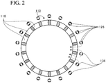
- FIG. 2 is a view showing the fuel injection port 126 and shows a cross-sectional view taken along line II-II of FIG. 1 .
- the fuel injection port 126 is provided radially outside the cylinder 110 with respect to the scavenging port 118. Specifically, the fuel injection port 126 is provided to face an outer surface of the cylinder 110 between the adjacent scavenging ports 118. Also, the fuel injection port 126 is located within a range of the scavenging port 118 in the stroke direction of the piston 112.
- a plurality of fuel injection ports 126 are also provided in a circumferential direction of the cylinder 110 in accordance with the scavenging ports 118.
- one fuel pipe 136 through which a fuel gas is guided to each of the scavenging ports 118 extends in the stroke direction of the piston 112.
- the fuel pipe 136 is disposed radially outside the outer surface of the cylinder 110 between the adjacent scavenging ports 118, and a flow of the active gas is hardly obstructed by the fuel pipe 136.
- the fuel injection port 126 is an opening formed on an adjacent fuel pipe 136 side of the fuel pipes 136.
- the annular pipe 138 is disposed on an exhaust port 114 side (an upper side of FIG. 1 ) of the fuel pipe 136.
- the annular pipe 138 is a pipe which annularly surrounds a radial outside of the cylinder 110 in a circumferential direction of the cylinder 110 and is in communication with the fuel pipe 136.
- the fuel gas is guided from the fuel gas main pipe 140, in which the fuel gas is stored, to the annular pipe 138.
- the fuel injection port 126 injects the fuel gas, which is supplied from the fuel gas main pipe 140 through the annular pipe 138, to the active gas sucked into the scavenging port 118.
- the fuel gas is added to the flow of the active gas, as indicated by an arrow of a broken line in FIG. 2 , sucked from the scavenging port 118 into the cylinder 110 together with the active gas and then guided to the combustion chamber 124.
- FIG. 2 has described the case in which the fuel injection port 126 is opened toward the adjacent fuel pipe 136.
- the fuel injection port 126 is preferably formed so that the injected fuel gas is sucked into the scavenging port 118 together with the active gas.
- the fuel injection port 126 may be opened toward the scavenging port 118 and may be provided at any place.
- FIG. 2 has described the case in which the fuel pipes 136 and the scavenging ports 118 are disposed in the same number.
- the number of fuel pipes 136 that are arranged may be different from that of the scavenging ports 118.
- one fuel pipe 136 may be provided at every two scavenging ports 118.
- the pilot injection valve 142 is provided at the cylinder head 110a. Additionally, an appropriate amount of fuel oil is injected from the pilot injection valve 142 at a predetermined point of time in an engine cycle.
- the fuel oil is vaporized by heat of the combustion chamber 124 which is formed inside the cylinder 110 to be surrounded by the cylinder head 110a, the cylinder liner 110b, and the piston 112. Additionally, the fuel oil is vaporized, spontaneously ignited, and burned in a short time, and thus a temperature of the combustion chamber 124 is increased extremely. As a result, the fuel gas guided into the combustion chamber 124 can be reliably burned at a predetermined timing.
- the piston 112 reciprocates mainly due to an expansion pressure caused by the combustion of the fuel gas.
- the fuel gas is produced, for example, by gasifying liquefied natural gas (LNG).
- LNG liquefied natural gas
- the fuel gas is not limited to LNG, and, for example, liquefied petroleum gas (LPG), gas oil, heavy oil or the like may be gasified and applied as the fuel gas.
- LPG liquefied petroleum gas
- the fuel injection device 128 is provided on an upstream side of the fuel pipe 136 and the annular pipe 138 in the fuel supply passage 144 which communicates from the fuel gas main pipe 140 to the fuel injection port 126. Additionally, the fuel injection device 128 opens and closes the fuel supply passage 144 and controls injection of the fuel gas from the fuel injection port 126.
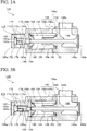
- FIGS. 3A and 3B are views showing the fuel injection device 128 and show schematic cross-sectional views of the fuel injection device 128 disposed on a left side of the cylinder 110 in FIG. 1 .
- the fuel injection device 128 disposed on a right side of the cylinder 110 in FIG. 1 has the same structure as that disposed on the left side, and thus a description thereof will be omitted.
- a casing 146 of the fuel injection device 128 is formed by two outer wall members 146a and 146b.
- the outer wall member 146a is located on a right side (the cylinder 110 side) in FIGS. 3A and 3B with respect to the outer wall member 146b, and a gas passage 148 through which the fuel gas flows is formed therein.
- a first end 148a of the gas passage 148 which is opened toward a right side of FIGS. 3A and 3B is in communication with the annular pipe 138, and a second end 148b thereof which is opened toward an upper side in FIGS. 3A and 3B is in communication with the fuel gas main pipe 140 through a pipe connected to a flange member 150.
- a protruding portion 154 is provided at a facing surface 152 which faces the outer wall member 146b.
- the protruding portion 154 protrudes from the facing surface 152 toward the outer wall member 146b.
- An annular groove 156 is formed at an outer circumference of a base side of the protruding portion 154.
- a through-hole 158 which passes through from an outer wall member 146b side to the gas passage 148 is formed in the protruding portion 154.
- a first end 160a of a fuel injection valve 160 is inserted into the through-hole 158 from a gas passage 148 side.
- a valve body 160b is formed at a second end side of the fuel injection valve 160.
- the first end 148a of the gas passage 148 is opened and closed by the valve body 160b. That is, the fuel injection valve 160 is shifted to a closed state ( FIG. 3A ) in which fuel supply is stopped and an open state ( FIG. 3B ) in which fuel is supplied.
- a facing hole 164 having the same inner diameter as the groove 156 on the outer wall member 146a side is provided at a facing surface 162 thereof which faces the outer wall member 146a.
- a small diameter hole 166 having a diameter smaller than that of the facing hole 164 is formed at a bottom surface of the facing hole 164.
- an elastic spring 168 is disposed inside the facing hole 164, and a first end 168a thereof extends to the groove 156 and is fixed thereto. Further, a second end 168b of the elastic spring 168 is fixed to a valve spring retainer 170.
- the first end 160a of the fuel injection valve 160 passes through the valve spring retainer 170 and protrudes from the valve spring retainer 170 to the inside of the small diameter hole 166.
- the valve spring retainer 170 is fixed to the fuel injection valve 160, and in FIG. 3A , the fuel injection valve 160 is biased toward a left side of the drawing by a biasing force of the elastic spring 168, and thus the valve body 160b closes the first end 148a of the gas passage 148.
- the first end 160a of the fuel injection valve 160 is located inside the small diameter hole 166. Also, the first end 160a of the fuel injection valve 160 is in contact with an operating piston 172.
- the operating piston 172 is inserted into the small diameter hole 166 and also has a size at which it can slide in the small diameter hole 166 in a left and right direction of FIGS. 3A and 3B . Also, a first end 172a of the operating piston 172 is in contact with the first end 160a of the fuel injection valve 160, and a second end 172b thereof which is located on an opposite side faces a bottom surface 166a of the small diameter hole 166.
- a hydraulic chamber 174 is formed to be surrounded by the small diameter hole 166 and the operating piston 172. That is, the second end 172b of the operating piston 172 serves as a pressure receiving surface facing the hydraulic chamber 174.
- an oil guide hole 176 which is in communication with the hydraulic chamber 174 is formed at the outer wall member 146b, and the hydraulic oil is introduced into the hydraulic chamber 174 through the oil guide hole 176.
- a hydraulic pressure in the hydraulic chamber 174 is boosted by the hydraulic oil introduced into the hydraulic chamber 174, and when a pressing force due to the hydraulic pressure is increased higher than the biasing force of the elastic spring 168, the fuel injection valve 160 is pressed to a right side of the drawing, as shown in FIG. 3B , and the first end 148a of the gas passage 148 is opened.
- a threshold value of the hydraulic pressure in the hydraulic chamber 174 due to the biasing force of the elastic spring 168 is set, and when the pressure in the hydraulic chamber 174 is less than the threshold value, the operating piston 172 is held in a standby position in which the fuel injection valve 160 is maintained in the closed state ( FIG. 3A ). Additionally, when the pressure in the hydraulic chamber 174 is more than or equal to the threshold value, the operating piston 172 moves to an operating position in which the fuel injection valve 160 is maintained in the open state ( FIG. 3B ).
- a discharge port 178 is a hole which passes through from the small diameter hole 166, in which the operating piston 172 is inserted, to the outside of the outer wall member 146b and discharges the hydraulic oil leaking from the hydraulic chamber 174 to the facing hole 164 side according to sliding of the operating piston 172 to the outside of the outer wall member 146b.
- bypass hole 180 is provided in the operating piston 172.
- a first end 180a of the bypass hole 180 is opened to the second end 172b (the pressure receiving surface) of the operating piston 172, and a second end 180b of the bypass hole 180 is opened to a sliding surface 172c which slides along an inner wall of the small diameter hole 166.
- the bypass hole 180 and the flow of the hydraulic oil will be described in detail.
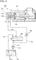
- FIGS. 4 and 5 are views showing the fuel injection device 128 and the flow of the hydraulic oil.
- FIG. 4 shows a state in which the fuel injection valve 160 is closed
- FIG. 5 shows a state in which the fuel injection valve 160 is open.
- a hydraulic pump 186 for discharging the hydraulic oil is connected to a hydraulic oil tank 184. Additionally, a first supply pipe 190 is connected to an outlet port of the hydraulic pump 186, and a P port of a switching valve 188 having two positions and three ports is connected to the first supply pipe 190. A circulation pipe 192 which extends to the discharge port 178 is branched from the first supply pipe 190, and a throttle valve 194 is provided at the circulation pipe 192.
- an A port of the switching valve 188 and the oil guide hole 176 are in communication with each other through a hydraulic oil inlet pipe 196, and a T port of the switching valve 188 and the hydraulic oil tank 184 are in communication with each other through a return pipe 198.
- a plurality of plate members 184a for removing bubbles are disposed in the hydraulic oil tank 184, and the hydraulic oil in the hydraulic oil tank 184 is warmed by a heater which is not shown.
- the switching valve 188 When the switching valve 188 is located at a switching position shown in FIG. 4 , the P port of the switching valve 188 is cut off, the A port and the T port are in communication with each other, and the hydraulic chamber 174 is in communication with the hydraulic oil tank 184 through the hydraulic oil inlet pipe 196 and the return pipe 198. Therefore, the hydraulic pressure is not applied to the hydraulic chamber 174, and the fuel injection valve 160 is closed by the biasing force of the elastic spring 168.
- the hydraulic oil pressurized by the hydraulic pump 186 passes through the throttle valve 194 and is introduced into the discharge port 178.
- the discharge port 178 faces the second end 180b of the bypass hole 180 in a state in which the operating piston 172 is held in the standby position shown in FIG. 4 , and the hydraulic oil is introduced from the discharge port 178 to the hydraulic chamber 174 through the bypass hole 180.
- the hydraulic oil introduced into the hydraulic chamber 174 flows to the A port of the switching valve 188 through the oil guide hole 176 and the hydraulic oil inlet pipe 196.
- the A port of the switching valve 188 is in communication with the T port, and the hydraulic oil circulates to the hydraulic oil tank 184 through the A port, the T port and the return pipe 198.
- the hydraulic oil guided from the hydraulic pump 186 to the hydraulic chamber 174 is discharged from the hydraulic chamber 174 through the oil guide hole 176, and thus the hydraulic oil is circulated. Accordingly, the hydraulic oil warmed in the hydraulic oil tank 184 is circulated to minimize a temperature drop of the hydraulic fluid in a circulation route, and thus operation accuracy of the fuel injection valve 160 can be enhanced. Also, since the bypass hole 180 is provided in the operating piston 172, a temperature drop of the operating piston 172 can also be minimized by the circulated hydraulic oil. Further, since the hydraulic oil tank 184 is included in the circulation route of the hydraulic oil, defoaming of bubbles can be enabled by the plate members 184a inside the hydraulic oil tank 184.
- the switching valve 188 when the switching valve 188 is located at the switching position shown in FIG. 5 , the T port of the switching valve 188 is cut off, the P port and the A port are in communication with each other, and the hydraulic chamber 174 is in communication with the hydraulic pump 186 through the hydraulic oil inlet pipe 196 and the first supply pipe 190. Therefore, the hydraulic pressure is applied to the hydraulic chamber 174, and the fuel injection valve 160 is pressed and opened by the hydraulic pressure.
- the switching valve 188 is switched to a first switching position ( FIG. 5 ) in which the hydraulic oil discharged from the hydraulic pump 186 is guided to the hydraulic chamber 174 and a second switching position ( FIG. 4 ) in which the hydraulic oil discharged from the hydraulic pump 186 is guided to the discharge port 178.
- a passage cross section of the bypass hole 180 is sufficiently small with respect to the pressure receiving surface of the operating piston 172, a discharge amount of the hydraulic oil discharged from the hydraulic chamber 174 through the bypass hole 180 and the discharge port 178 is minimized when the fuel injection valve 160 is switched from the closed state to the open state. Accordingly, it is possible to suppress deterioration in responsiveness when the fuel injection valve 160 is opened.
- the bypass hole 180 guides the hydraulic oil discharged from the hydraulic pump 186 to the hydraulic chamber 174.
- the bypass hole 180 may discharge the hydraulic oil discharged from the hydraulic pump 186 from the hydraulic chamber 174.
- the hydraulic pump 186 may be constituted in a variable capacity type to lower a discharge pressure and may control the hydraulic pressure in the hydraulic chamber 174 not to be the above-described threshold value or more. In either case, when the hydraulic oil flows through the bypass hole 180, the temperature drop of the hydraulic oil can be minimized, and thus the operation accuracy of the fuel injection valve 160 can be enhanced.
- the discharge port 178 is provided at the casing 146, and the discharge port 178 faces the second end 180b of the bypass hole 180 while the operating piston 172 is held in the standby position and does not face the second end 180b of the bypass hole 180 when the operating piston 172 moves to the operating position. Additionally, while the operating piston 172 is held in the standby position, the hydraulic chamber 174 and the discharge port 178 are in communication with each other, and the hydraulic oil flows through the bypass hole 180, and when the operating piston 172 moves to the operating position, the communication between the hydraulic chamber 174 and the discharge port 178 is cut off.
- the discharge port 178 is not indispensable, and it may not be a constitution in which the communication state between the hydraulic chamber 174 and the discharge port 178 is changed depending on whether or not the discharge port 178 and the bypass hole 180 face each other.
- the discharge port 178 and the bypass hole 180 in the above-described positional relationship, the second end 180b of the bypass hole 180 is closed when the operating piston 172 moves from the standby position toward the operating position, and the deterioration of the responsiveness when the fuel injection valve 160 is opened can be suppressed.
- the switching valve 188 which is switched to the first switching position and the second switching position is provided.
- the hydraulic pump 186 is constituted in the variable capacity type to lower the discharge pressure and controls the hydraulic pressure in the hydraulic chamber 174 not to be the above-described threshold value or more
- the switching valve 188 is not indispensable.
- the opening and closing of the fuel injection valve 160 can be switched by providing the switching valve 188.
- the temperature drop of the hydraulic oil is minimized by circulating the hydraulic oil to the hydraulic oil tank 184 and heating the hydraulic oil.
- a cooler for cooling the hydraulic oil in the hydraulic oil tank 184 may be provided, and the hydraulic oil may be circulated to the hydraulic oil tank 184 to be cooled, and thus a temperature rise of the hydraulic oil may be minimized.
- the fuel injection device 128 is provided at the fuel supply passage 144 which communicates from the fuel gas main pipe 140 to the fuel injection port 126.
- the fuel injection device 128 may perform a fuel oil injection process by opening and closing, for example, the pilot injection valve 142.
- the fuel injection valve 160 is the pilot injection valve 142. That is, the fuel injected by the fuel injection device 128 may be a fuel gas or a liquid fuel.
- the present disclosure can be applied to a hydraulically driven fuel injection device having an operating piston operated by a hydraulic pressure, and an engine.
Landscapes
- Engineering & Computer Science (AREA)
- General Engineering & Computer Science (AREA)
- Chemical & Material Sciences (AREA)
- Mechanical Engineering (AREA)
- Combustion & Propulsion (AREA)
- Physics & Mathematics (AREA)
- Fluid Mechanics (AREA)
- Analytical Chemistry (AREA)
- Chemical Kinetics & Catalysis (AREA)
- General Chemical & Material Sciences (AREA)
- Oil, Petroleum & Natural Gas (AREA)
- Fuel-Injection Apparatus (AREA)
Abstract
Description
- The present disclosure relates to a hydraulically driven fuel injection device having an operating piston operated by a hydraulic pressure, and an engine.
- Priority is claimed on Japanese Patent Application No.
2015-96718, filed May 11, 2015 - A fuel injection device for supplying fuel to a combustion chamber is provided in an engine. For example, as described in Patent Document 1, in the hydraulically driven fuel injection device, a hydraulic pressure of a hydraulic oil acts on the hydraulic chamber, and thus a piston is pressed. A fuel injection valve is opened and closed by displacement of the piston, and thus supply or stop of the fuel is controlled.
- Japanese Unexamined Patent Application, First Publication No.
2001-527614 - However, in the hydraulically driven fuel injection device, since the hydraulic chamber is fully filled with the hydraulic oil and the hydraulic oil does not flow much when only the fuel injection valve is opened and closed, a temperature of the hydraulic oil in the hydraulic chamber or an oil passage near the hydraulic chamber is increased or conversely reduced as time elapses. As a result, the viscosity of the hydraulic oil is changed, and a deviation in timing and duration of the opening and closing of the fuel injection valve is generated, and thus the operation accuracy thereof may be reduced.
- The present disclosure is made in view of such problems, and an object of the present disclosure is to provide a hydraulically driven fuel injection device in which operation accuracy of a fuel injection valve is enhanced by suppressing a temperature change in a hydraulic oil, and an engine.
- In order to achieve the aforementioned objects, a first aspect of the present disclosure provides a fuel injection device having a fuel injection valve which is changed between a closed state in which supply of a fuel is stopped and an open state in which the fuel is supplied. The fuel injection device includes a hydraulic pump configured to discharge a hydraulic oil, a casing in which a hydraulic chamber connected to the hydraulic pump is provided, an operating piston slidably provided inside the casing such that, when a pressure in the hydraulic chamber is less than a preset threshold value, the operating piston is held in a standby position in which the fuel injection valve is maintained in the closed state, and when the pressure in the hydraulic chamber is more than or equal to the threshold value, the operating piston moves to an operating position in which the fuel injection valve is set to the open state, and a bypass hole formed in the operating piston and configured to guide the hydraulic oil discharged from the hydraulic pump into the hydraulic chamber or to discharge, from the hydraulic chamber, the hydraulic oil guided into the hydraulic chamber from the hydraulic pump, while the operating piston is held in the standby position.
- Also, an engine of the present disclosure includes the fuel injection device.
- According to the present disclosure, it is possible to enhance operation accuracy of a fuel injection valve by suppressing a temperature change of a hydraulic oil.
-
-
FIG. 1 is a view showing an entire constitution of a uniflow scavenging two-cycle engine. -
FIG. 2 is a view showing a fuel injection port -
FIG. 3A is a view showing a fuel injection device. -
FIG. 3B is a view showing the fuel injection device. -
FIG. 4 is a view showing the fuel injection device and a flow of a hydraulic oil. -
FIG. 5 is a view showing the fuel injection device and the flow of the hydraulic oil. - Hereinafter, preferred embodiments of the present disclosure will be described in detail with reference to the accompanying drawings. Dimensions, materials, other specific numerical values, and so on indicated in these embodiments are merely examples for facilitating comprehension of the disclosure, and unless indicated otherwise, the present disclosure is not limited thereto. Note that in the specification and drawings, elements having substantially the same functions and constitutions will be given the same reference numerals, and a duplicate description thereof will be omitted. Further, elements not directly related to the present disclosure are not shown in the drawings.
-
FIG. 1 is a view showing an entire constitution of a uniflow scavenging two-cycle engine 100. The uniflow scavenging two-cycle engine 100 of the embodiment is used in, for example, a ship. Specifically, the uniflow scavenging two-cycle engine 100 includes acylinder 110, apiston 112, anexhaust port 114, anexhaust valve 116, ascavenging port 118, ascavenging reservoir 120, ascavenging chamber 122, acombustion chamber 124, afuel injection port 126, afuel injection device 128, acooler 130, aguide vane 132, adrain separator 134, afuel pipe 136, anannular pipe 138, a fuel gasmain pipe 140, apilot injection valve 142 and afuel supply passage 144. - In the uniflow scavenging two-
cycle engine 100, exhaust, intake, compression, combustion and expansion are performed between two strokes, an up-stroke and a down-stroke, of thepiston 112, and thepiston 112 is slid in thecylinder 110. A first end of apiston rod 112a is fixed to thepiston 112. Also, a crosshead which is not shown is connected to a second end of thepiston rod 112a, and the crosshead reciprocates together with thepiston 112. When the crosshead reciprocates according to reciprocating movement of thepiston 112, a crankshaft which is not shown is rotated in conjunction with the reciprocating movement thereof. - The
exhaust port 114 is an opening provided at acylinder head 110a located above a top dead center of thepiston 112 and is opened and closed to exhaust an exhaust gas generated in thecylinder 110 after combustion. Theexhaust valve 116 is moved up and down at a predetermined timing by an exhaust valve drive unit 116a to open and close theexhaust port 114. When theexhaust port 114 is opened, the exhaust gas is exhausted from thecylinder 110 through theexhaust port 114. - The
scavenging port 118 is a hole which passes through from an inner circumferential surface (an inner circumferential surface of acylinder liner 110b) on a lower end side of thecylinder 110 to an outer circumferential surface thereof, and a plurality ofscavenging ports 118 are provided all around thecylinder 110. Additionally, thescavenging port 118 sucks an active gas into thecylinder 110 according to a sliding motion of thepiston 112. The active gas includes an oxidizer such as oxygen, ozone or the like, or a mixture thereof (e.g., air). - The active gas (e.g., air) compressed by a blower which is not shown is cooled by the cooler 130 and sealed in the
scavenging reservoir 120. The compressed and cooled active gas is distributed by theguide vane 132 disposed in thescavenging reservoir 120, and then moisture is removed by thedrain separator 134. - The
scavenging chamber 122 is in communication with thescavenging reservoir 120 and also surrounds a second end side (a lower side inFIG. 1 ) of thecylinder 110 in a stroke direction of thepiston 112, and the compressed, cooled and dehydrated active gas is introduced therein. - The
scavenging port 118 is provided at a portion of the cylinder 110 (thecylinder liner 110b) which is located inside thescavenging chamber 122 and sucks the active gas from thescavenging chamber 122 into thecylinder 110 due to a differential pressure between thescavenging chamber 122 and thecylinder 110 according to the sliding motion of thepiston 112. The active gas sucked into thecylinder 110 is guided to thecombustion chamber 124 by thepiston 112. -
FIG. 2 is a view showing thefuel injection port 126 and shows a cross-sectional view taken along line II-II ofFIG. 1 . As shown inFIG. 2 , thefuel injection port 126 is provided radially outside thecylinder 110 with respect to thescavenging port 118. Specifically, thefuel injection port 126 is provided to face an outer surface of thecylinder 110 between theadjacent scavenging ports 118. Also, thefuel injection port 126 is located within a range of thescavenging port 118 in the stroke direction of thepiston 112. - In the embodiment, since the plurality of
scavenging ports 118 are provided all around the uniflow scavenging two-cycle engine 100, a plurality offuel injection ports 126 are also provided in a circumferential direction of thecylinder 110 in accordance with thescavenging ports 118. Specifically, onefuel pipe 136 through which a fuel gas is guided to each of thescavenging ports 118 extends in the stroke direction of thepiston 112. Further, thefuel pipe 136 is disposed radially outside the outer surface of thecylinder 110 between theadjacent scavenging ports 118, and a flow of the active gas is hardly obstructed by thefuel pipe 136. Also, thefuel injection port 126 is an opening formed on anadjacent fuel pipe 136 side of thefuel pipes 136. - The
annular pipe 138 is disposed on anexhaust port 114 side (an upper side ofFIG. 1 ) of thefuel pipe 136. Theannular pipe 138 is a pipe which annularly surrounds a radial outside of thecylinder 110 in a circumferential direction of thecylinder 110 and is in communication with thefuel pipe 136. The fuel gas is guided from the fuel gasmain pipe 140, in which the fuel gas is stored, to theannular pipe 138. - The
fuel injection port 126 injects the fuel gas, which is supplied from the fuel gasmain pipe 140 through theannular pipe 138, to the active gas sucked into thescavenging port 118. As a result, the fuel gas is added to the flow of the active gas, as indicated by an arrow of a broken line inFIG. 2 , sucked from thescavenging port 118 into thecylinder 110 together with the active gas and then guided to thecombustion chamber 124. - The example of
FIG. 2 has described the case in which thefuel injection port 126 is opened toward theadjacent fuel pipe 136. However, thefuel injection port 126 is preferably formed so that the injected fuel gas is sucked into the scavengingport 118 together with the active gas. For example, thefuel injection port 126 may be opened toward the scavengingport 118 and may be provided at any place. - Further, the example of
FIG. 2 has described the case in which thefuel pipes 136 and the scavengingports 118 are disposed in the same number. However, the number offuel pipes 136 that are arranged may be different from that of the scavengingports 118. For example, onefuel pipe 136 may be provided at every two scavengingports 118. - Further, as shown in
FIG. 1 , thepilot injection valve 142 is provided at thecylinder head 110a. Additionally, an appropriate amount of fuel oil is injected from thepilot injection valve 142 at a predetermined point of time in an engine cycle. The fuel oil is vaporized by heat of thecombustion chamber 124 which is formed inside thecylinder 110 to be surrounded by thecylinder head 110a, thecylinder liner 110b, and thepiston 112. Additionally, the fuel oil is vaporized, spontaneously ignited, and burned in a short time, and thus a temperature of thecombustion chamber 124 is increased extremely. As a result, the fuel gas guided into thecombustion chamber 124 can be reliably burned at a predetermined timing. Thepiston 112 reciprocates mainly due to an expansion pressure caused by the combustion of the fuel gas. - Here, the fuel gas is produced, for example, by gasifying liquefied natural gas (LNG). Also, the fuel gas is not limited to LNG, and, for example, liquefied petroleum gas (LPG), gas oil, heavy oil or the like may be gasified and applied as the fuel gas.
- The
fuel injection device 128 is provided on an upstream side of thefuel pipe 136 and theannular pipe 138 in thefuel supply passage 144 which communicates from the fuel gasmain pipe 140 to thefuel injection port 126. Additionally, thefuel injection device 128 opens and closes thefuel supply passage 144 and controls injection of the fuel gas from thefuel injection port 126. -
FIGS. 3A and 3B are views showing thefuel injection device 128 and show schematic cross-sectional views of thefuel injection device 128 disposed on a left side of thecylinder 110 inFIG. 1 . Thefuel injection device 128 disposed on a right side of thecylinder 110 inFIG. 1 has the same structure as that disposed on the left side, and thus a description thereof will be omitted. - As shown in
FIGS. 3A and 3B , acasing 146 of thefuel injection device 128 is formed by twoouter wall members outer wall member 146a is located on a right side (thecylinder 110 side) inFIGS. 3A and 3B with respect to theouter wall member 146b, and agas passage 148 through which the fuel gas flows is formed therein. - A
first end 148a of thegas passage 148 which is opened toward a right side ofFIGS. 3A and 3B is in communication with theannular pipe 138, and asecond end 148b thereof which is opened toward an upper side inFIGS. 3A and 3B is in communication with the fuel gasmain pipe 140 through a pipe connected to aflange member 150. - Also, in the
outer wall member 146a, a protrudingportion 154 is provided at a facingsurface 152 which faces theouter wall member 146b. The protrudingportion 154 protrudes from the facingsurface 152 toward theouter wall member 146b. Anannular groove 156 is formed at an outer circumference of a base side of the protrudingportion 154. - Additionally, a through-
hole 158 which passes through from anouter wall member 146b side to thegas passage 148 is formed in the protrudingportion 154. Afirst end 160a of afuel injection valve 160 is inserted into the through-hole 158 from agas passage 148 side. Avalve body 160b is formed at a second end side of thefuel injection valve 160. Thefirst end 148a of thegas passage 148 is opened and closed by thevalve body 160b. That is, thefuel injection valve 160 is shifted to a closed state (FIG. 3A ) in which fuel supply is stopped and an open state (FIG. 3B ) in which fuel is supplied. - In the
outer wall member 146b, a facinghole 164 having the same inner diameter as thegroove 156 on theouter wall member 146a side is provided at a facingsurface 162 thereof which faces theouter wall member 146a. Asmall diameter hole 166 having a diameter smaller than that of the facinghole 164 is formed at a bottom surface of the facinghole 164. Additionally, anelastic spring 168 is disposed inside the facinghole 164, and a first end 168a thereof extends to thegroove 156 and is fixed thereto. Further, asecond end 168b of theelastic spring 168 is fixed to avalve spring retainer 170. - The
first end 160a of thefuel injection valve 160 passes through thevalve spring retainer 170 and protrudes from thevalve spring retainer 170 to the inside of thesmall diameter hole 166. Thevalve spring retainer 170 is fixed to thefuel injection valve 160, and inFIG. 3A , thefuel injection valve 160 is biased toward a left side of the drawing by a biasing force of theelastic spring 168, and thus thevalve body 160b closes thefirst end 148a of thegas passage 148. - As described above, the
first end 160a of thefuel injection valve 160 is located inside thesmall diameter hole 166. Also, thefirst end 160a of thefuel injection valve 160 is in contact with anoperating piston 172. Theoperating piston 172 is inserted into thesmall diameter hole 166 and also has a size at which it can slide in thesmall diameter hole 166 in a left and right direction ofFIGS. 3A and 3B . Also, afirst end 172a of theoperating piston 172 is in contact with thefirst end 160a of thefuel injection valve 160, and asecond end 172b thereof which is located on an opposite side faces abottom surface 166a of thesmall diameter hole 166. - A
hydraulic chamber 174 is formed to be surrounded by thesmall diameter hole 166 and theoperating piston 172. That is, thesecond end 172b of theoperating piston 172 serves as a pressure receiving surface facing thehydraulic chamber 174. - Also, an
oil guide hole 176 which is in communication with thehydraulic chamber 174 is formed at theouter wall member 146b, and the hydraulic oil is introduced into thehydraulic chamber 174 through theoil guide hole 176. A hydraulic pressure in thehydraulic chamber 174 is boosted by the hydraulic oil introduced into thehydraulic chamber 174, and when a pressing force due to the hydraulic pressure is increased higher than the biasing force of theelastic spring 168, thefuel injection valve 160 is pressed to a right side of the drawing, as shown inFIG. 3B , and thefirst end 148a of thegas passage 148 is opened. - Conversely, when the hydraulic pressure in the
hydraulic chamber 174 drops and the pressing force due to the hydraulic pressure becomes smaller than the biasing force of theelastic spring 168, thefuel injection valve 160 is pressed to a left side of the drawing, as shown inFIG. 3A , and thefirst end 148a of thegas passage 148 is closed. - That is, a threshold value of the hydraulic pressure in the
hydraulic chamber 174 due to the biasing force of theelastic spring 168 is set, and when the pressure in thehydraulic chamber 174 is less than the threshold value, theoperating piston 172 is held in a standby position in which thefuel injection valve 160 is maintained in the closed state (FIG. 3A ). Additionally, when the pressure in thehydraulic chamber 174 is more than or equal to the threshold value, theoperating piston 172 moves to an operating position in which thefuel injection valve 160 is maintained in the open state (FIG. 3B ). - A
discharge port 178 is a hole which passes through from thesmall diameter hole 166, in which theoperating piston 172 is inserted, to the outside of theouter wall member 146b and discharges the hydraulic oil leaking from thehydraulic chamber 174 to the facinghole 164 side according to sliding of theoperating piston 172 to the outside of theouter wall member 146b. - Furthermore, a
bypass hole 180 is provided in theoperating piston 172. Afirst end 180a of thebypass hole 180 is opened to thesecond end 172b (the pressure receiving surface) of theoperating piston 172, and asecond end 180b of thebypass hole 180 is opened to a slidingsurface 172c which slides along an inner wall of thesmall diameter hole 166. Hereinafter, thebypass hole 180 and the flow of the hydraulic oil will be described in detail. -
FIGS. 4 and5 are views showing thefuel injection device 128 and the flow of the hydraulic oil.FIG. 4 shows a state in which thefuel injection valve 160 is closed, andFIG. 5 shows a state in which thefuel injection valve 160 is open. - As shown in
FIGS. 4 and5 , ahydraulic pump 186 for discharging the hydraulic oil is connected to ahydraulic oil tank 184. Additionally, afirst supply pipe 190 is connected to an outlet port of thehydraulic pump 186, and a P port of a switchingvalve 188 having two positions and three ports is connected to thefirst supply pipe 190. Acirculation pipe 192 which extends to thedischarge port 178 is branched from thefirst supply pipe 190, and athrottle valve 194 is provided at thecirculation pipe 192. - Also, an A port of the switching
valve 188 and theoil guide hole 176 are in communication with each other through a hydraulicoil inlet pipe 196, and a T port of the switchingvalve 188 and thehydraulic oil tank 184 are in communication with each other through areturn pipe 198. A plurality ofplate members 184a for removing bubbles are disposed in thehydraulic oil tank 184, and the hydraulic oil in thehydraulic oil tank 184 is warmed by a heater which is not shown. - When the switching
valve 188 is located at a switching position shown inFIG. 4 , the P port of the switchingvalve 188 is cut off, the A port and the T port are in communication with each other, and thehydraulic chamber 174 is in communication with thehydraulic oil tank 184 through the hydraulicoil inlet pipe 196 and thereturn pipe 198. Therefore, the hydraulic pressure is not applied to thehydraulic chamber 174, and thefuel injection valve 160 is closed by the biasing force of theelastic spring 168. - At this point, the hydraulic oil pressurized by the
hydraulic pump 186 passes through thethrottle valve 194 and is introduced into thedischarge port 178. Thedischarge port 178 faces thesecond end 180b of thebypass hole 180 in a state in which theoperating piston 172 is held in the standby position shown inFIG. 4 , and the hydraulic oil is introduced from thedischarge port 178 to thehydraulic chamber 174 through thebypass hole 180. - Additionally, the hydraulic oil introduced into the
hydraulic chamber 174 flows to the A port of the switchingvalve 188 through theoil guide hole 176 and the hydraulicoil inlet pipe 196. The A port of the switchingvalve 188 is in communication with the T port, and the hydraulic oil circulates to thehydraulic oil tank 184 through the A port, the T port and thereturn pipe 198. - As described above, while the
operating piston 172 is held in the standby position, the hydraulic oil guided from thehydraulic pump 186 to thehydraulic chamber 174 is discharged from thehydraulic chamber 174 through theoil guide hole 176, and thus the hydraulic oil is circulated. Accordingly, the hydraulic oil warmed in thehydraulic oil tank 184 is circulated to minimize a temperature drop of the hydraulic fluid in a circulation route, and thus operation accuracy of thefuel injection valve 160 can be enhanced. Also, since thebypass hole 180 is provided in theoperating piston 172, a temperature drop of theoperating piston 172 can also be minimized by the circulated hydraulic oil. Further, since thehydraulic oil tank 184 is included in the circulation route of the hydraulic oil, defoaming of bubbles can be enabled by theplate members 184a inside thehydraulic oil tank 184. - Meanwhile, when the switching
valve 188 is located at the switching position shown inFIG. 5 , the T port of the switchingvalve 188 is cut off, the P port and the A port are in communication with each other, and thehydraulic chamber 174 is in communication with thehydraulic pump 186 through the hydraulicoil inlet pipe 196 and thefirst supply pipe 190. Therefore, the hydraulic pressure is applied to thehydraulic chamber 174, and thefuel injection valve 160 is pressed and opened by the hydraulic pressure. - In this way, the switching
valve 188 is switched to a first switching position (FIG. 5 ) in which the hydraulic oil discharged from thehydraulic pump 186 is guided to thehydraulic chamber 174 and a second switching position (FIG. 4 ) in which the hydraulic oil discharged from thehydraulic pump 186 is guided to thedischarge port 178. - When the
operating piston 172 moves to an operating position shown inFIG. 5 , thedischarge port 178 does not face thesecond end 180b of thebypass hole 180, and thesecond end 180b of thebypass hole 180 is closed by the inner wall of thesmall diameter hole 166. As a result, the hydraulic oil pressurized in thehydraulic pump 186 flows to acirculation pipe 192 side, but a flow rate of the hydraulic oil is restricted by thethrottle valve 194, and thus an operation of theoperating piston 172 is not affected. - Further, since a passage cross section of the
bypass hole 180 is sufficiently small with respect to the pressure receiving surface of theoperating piston 172, a discharge amount of the hydraulic oil discharged from thehydraulic chamber 174 through thebypass hole 180 and thedischarge port 178 is minimized when thefuel injection valve 160 is switched from the closed state to the open state. Accordingly, it is possible to suppress deterioration in responsiveness when thefuel injection valve 160 is opened. - In the above-described embodiment, while the
operating piston 172 is maintained in the standby position, thebypass hole 180 guides the hydraulic oil discharged from thehydraulic pump 186 to thehydraulic chamber 174. However, while theoperating piston 172 is maintained in the standby position, thebypass hole 180 may discharge the hydraulic oil discharged from thehydraulic pump 186 from thehydraulic chamber 174. In this case, for example, thehydraulic pump 186 may be constituted in a variable capacity type to lower a discharge pressure and may control the hydraulic pressure in thehydraulic chamber 174 not to be the above-described threshold value or more. In either case, when the hydraulic oil flows through thebypass hole 180, the temperature drop of the hydraulic oil can be minimized, and thus the operation accuracy of thefuel injection valve 160 can be enhanced. - Also, in the above-described embodiment, the
discharge port 178 is provided at thecasing 146, and thedischarge port 178 faces thesecond end 180b of thebypass hole 180 while theoperating piston 172 is held in the standby position and does not face thesecond end 180b of thebypass hole 180 when theoperating piston 172 moves to the operating position. Additionally, while theoperating piston 172 is held in the standby position, thehydraulic chamber 174 and thedischarge port 178 are in communication with each other, and the hydraulic oil flows through thebypass hole 180, and when theoperating piston 172 moves to the operating position, the communication between thehydraulic chamber 174 and thedischarge port 178 is cut off. However, thedischarge port 178 is not indispensable, and it may not be a constitution in which the communication state between thehydraulic chamber 174 and thedischarge port 178 is changed depending on whether or not thedischarge port 178 and thebypass hole 180 face each other. However, by setting thedischarge port 178 and thebypass hole 180 in the above-described positional relationship, thesecond end 180b of thebypass hole 180 is closed when theoperating piston 172 moves from the standby position toward the operating position, and the deterioration of the responsiveness when thefuel injection valve 160 is opened can be suppressed. Further, in the above-described embodiment, when theoperating piston 172 moves slightly from the standby position toward the operating position, thesecond end 180b of thebypass hole 180 is closed before theoperating piston 172 reaches the operating position, and thus the deterioration of the responsiveness when thefuel injection valve 160 is opened can be further suppressed. - Also, in the above-described embodiment, the switching
valve 188 which is switched to the first switching position and the second switching position is provided. However, as described above, as long as thehydraulic pump 186 is constituted in the variable capacity type to lower the discharge pressure and controls the hydraulic pressure in thehydraulic chamber 174 not to be the above-described threshold value or more, the switchingvalve 188 is not indispensable. However, even if thehydraulic pump 186 is not constituted in the variable capacity type and is operated at a predetermined output, the opening and closing of thefuel injection valve 160 can be switched by providing the switchingvalve 188. - Also, in the above-described embodiment, the temperature drop of the hydraulic oil is minimized by circulating the hydraulic oil to the
hydraulic oil tank 184 and heating the hydraulic oil. However, for example, a cooler for cooling the hydraulic oil in thehydraulic oil tank 184 may be provided, and the hydraulic oil may be circulated to thehydraulic oil tank 184 to be cooled, and thus a temperature rise of the hydraulic oil may be minimized. - Also, in the above-described embodiment, the
fuel injection device 128 is provided at thefuel supply passage 144 which communicates from the fuel gasmain pipe 140 to thefuel injection port 126. However, thefuel injection device 128 may perform a fuel oil injection process by opening and closing, for example, thepilot injection valve 142. In this case, thefuel injection valve 160 is thepilot injection valve 142. That is, the fuel injected by thefuel injection device 128 may be a fuel gas or a liquid fuel. - While preferred embodiments of the present disclosure have been described above with reference to the accompanying drawings, the present disclosure is not limited to those examples. It is apparent that those who have ordinary skills in the art can make various changes or modifications within the scope of the technical spirit claimed herein, and it should be understood that those changes or modifications are within the technical scope of the present disclosure.
- The present disclosure can be applied to a hydraulically driven fuel injection device having an operating piston operated by a hydraulic pressure, and an engine.
-
- 100
- Uniflow scavenging two-cycle engine (engine)
- 128
- Fuel injection device
- 146
- Casing
- 160
- Fuel injection valve
- 172
- Operating piston
- 172b
- Second end (pressure receiving surface)
- 172c
- Sliding surface (surface different from pressure receiving surface)
- 174
- Hydraulic chamber
- 178
- Discharge port
- 180
- Bypass hole
- 180a
- First end
- 180b
- Second end
- 186
- Hydraulic pump
- 188
- Switching valve
Claims (4)
- A fuel injection device having a fuel injection valve which is changed between a closed state in which supply of a fuel is stopped and an open state in which the fuel is supplied, comprising:a hydraulic pump configured to discharge a hydraulic oil,a casing in which a hydraulic chamber connected to the hydraulic pump is provided,an operating piston slidably provided inside the casing such that, when a pressure in the hydraulic chamber is less than a preset threshold value, the operating piston is held in a standby position in which the fuel injection valve is maintained in the closed state, and when the pressure in the hydraulic chamber is more than or equal to the threshold value, the operating piston moves to an operating position in which the fuel injection valve is set to the open state, anda bypass hole formed in the operating piston and configured to guide the hydraulic oil discharged from the hydraulic pump into the hydraulic chamber or to discharge, from the hydraulic chamber, the hydraulic oil guided into the hydraulic chamber from the hydraulic pump, while the operating piston is held in the standby position.
- The fuel injection device according to claim 1, wherein the operating piston has a pressure receiving surface which faces the hydraulic chamber, a first end of the bypass hole is opened to the pressure receiving surface, and a second end of the bypass hole is opened to a surface different from the pressure receiving surface, and
a discharge port which faces the second end of the bypass hole while the operating piston is held in the standby position and does not face the second end of the bypass hole when the operating piston moves the operating position is provided at the casing, the hydraulic chamber and the discharge port are in communication with each other while the operating piston is held in the standby position, and the communication between the hydraulic chamber and the discharge port is cut off when the operating piston moves to the operating position. - The fuel injection device according to claim 2, comprising a switching valve which is switched to a first switching position in which the hydraulic oil discharged from the hydraulic pump is guided to the hydraulic chamber and a second switching position in which the hydraulic oil discharged from the hydraulic pump is guided to the discharge port.
- An engine having the fuel injection device according to any one of claims 1 to 3.
Applications Claiming Priority (2)
| Application Number | Priority Date | Filing Date | Title |
|---|---|---|---|
| JP2015096718A JP6524788B2 (en) | 2015-05-11 | 2015-05-11 | Fuel injection device and engine |
| PCT/JP2016/064043 WO2016181999A1 (en) | 2015-05-11 | 2016-05-11 | Fuel injection device and engine |
Publications (3)
| Publication Number | Publication Date |
|---|---|
| EP3296557A1 true EP3296557A1 (en) | 2018-03-21 |
| EP3296557A4 EP3296557A4 (en) | 2018-10-03 |
| EP3296557B1 EP3296557B1 (en) | 2020-11-25 |
Family
ID=57248891
Family Applications (1)
| Application Number | Title | Priority Date | Filing Date |
|---|---|---|---|
| EP16792724.3A Active EP3296557B1 (en) | 2015-05-11 | 2016-05-11 | Fuel injection device and engine |
Country Status (6)
| Country | Link |
|---|---|
| EP (1) | EP3296557B1 (en) |
| JP (1) | JP6524788B2 (en) |
| KR (1) | KR101905803B1 (en) |
| CN (1) | CN107429646B (en) |
| DK (1) | DK3296557T3 (en) |
| WO (1) | WO2016181999A1 (en) |
Cited By (1)
| Publication number | Priority date | Publication date | Assignee | Title |
|---|---|---|---|---|
| WO2022167145A1 (en) * | 2021-02-02 | 2022-08-11 | Bernd Niethammer | Injector for blowing a gas into a combustion chamber or into an intake manifold of a motor vehicle |
Families Citing this family (2)
| Publication number | Priority date | Publication date | Assignee | Title |
|---|---|---|---|---|
| CN110284977A (en) * | 2019-06-12 | 2019-09-27 | 拓尔普科技有限公司 | A kind of high low grade Full-automatic cutting changes fuel supply method |
| EP4187067A1 (en) | 2021-11-24 | 2023-05-31 | Winterthur Gas & Diesel Ltd. | Internal combustion engine |
Family Cites Families (18)
| Publication number | Priority date | Publication date | Assignee | Title |
|---|---|---|---|---|
| JPS599091Y2 (en) * | 1979-03-02 | 1984-03-22 | 株式会社デンソー | Fuel injection valve for internal combustion engine |
| JPS59183066A (en) * | 1983-04-04 | 1984-10-18 | Nissan Motor Co Ltd | Fuel injection nozzle for diesel engine |
| JPH01141311U (en) * | 1988-03-23 | 1989-09-28 | ||
| JPH087090Y2 (en) * | 1990-04-13 | 1996-02-28 | 三菱自動車工業株式会社 | Fuel injection device for diesel engine |
| JPH0466768A (en) * | 1990-07-05 | 1992-03-03 | Yamaha Motor Co Ltd | High-pressure fuel injection device of engine |
| JPH07332043A (en) * | 1994-06-13 | 1995-12-19 | Toyota Motor Corp | Hydraulic valve system of internal combustion engine |
| JPH08246980A (en) * | 1995-03-07 | 1996-09-24 | Nippondenso Co Ltd | Safety device for accumulator fuel injection system |
| AT2854U1 (en) * | 1995-06-06 | 1999-05-25 | Avl Verbrennungskraft Messtech | STORAGE INJECTION SYSTEM FOR DIESEL INTERNAL COMBUSTION ENGINES |
| US5992387A (en) * | 1996-04-04 | 1999-11-30 | Caterpillar, Inc. | Fuel system having priming actuating fluid reservoir |
| JP2828033B2 (en) * | 1996-05-28 | 1998-11-25 | 三菱自動車工業株式会社 | Fuel injection device |
| JPH11236864A (en) * | 1998-02-20 | 1999-08-31 | Isuzu Motors Ltd | Fuel injection device for internal combustion engine |
| JP2000240534A (en) * | 1999-02-23 | 2000-09-05 | Yanmar Diesel Engine Co Ltd | High close valve pressure fuel injection device |
| JP2000249016A (en) * | 1999-03-01 | 2000-09-12 | Isuzu Motors Ltd | Injector |
| DE10118276A1 (en) * | 2001-04-12 | 2002-10-17 | Bosch Gmbh Robert | Fuel injection valve has helical element in receiving part with input channels for each inlet end of helical channel |
| DE102011080346A1 (en) * | 2011-08-03 | 2013-02-07 | Robert Bosch Gmbh | Injection device, internal combustion engine and method for operating an internal combustion engine |
| JP5820185B2 (en) | 2011-08-12 | 2015-11-24 | 株式会社Ihi | 2-cycle engine |
| DE102012204248A1 (en) * | 2012-03-19 | 2013-09-19 | Robert Bosch Gmbh | High-pressure fuel pump for fuel injection system of self-igniting internal combustion engine, comprises hydraulic chambers arranged on both sides of spring plate, which are hydraulically interconnected by throttle formed in throttle gap |
| JP6036128B2 (en) * | 2012-10-03 | 2016-11-30 | 株式会社Ihi | Uniflow scavenging 2-cycle engine |
-
2015
- 2015-05-11 JP JP2015096718A patent/JP6524788B2/en active Active
-
2016
- 2016-05-11 CN CN201680022626.XA patent/CN107429646B/en active Active
- 2016-05-11 WO PCT/JP2016/064043 patent/WO2016181999A1/en unknown
- 2016-05-11 DK DK16792724.3T patent/DK3296557T3/en active
- 2016-05-11 EP EP16792724.3A patent/EP3296557B1/en active Active
- 2016-05-11 KR KR1020177017269A patent/KR101905803B1/en active IP Right Grant
Cited By (1)
| Publication number | Priority date | Publication date | Assignee | Title |
|---|---|---|---|---|
| WO2022167145A1 (en) * | 2021-02-02 | 2022-08-11 | Bernd Niethammer | Injector for blowing a gas into a combustion chamber or into an intake manifold of a motor vehicle |
Also Published As
| Publication number | Publication date |
|---|---|
| CN107429646A (en) | 2017-12-01 |
| JP2016211463A (en) | 2016-12-15 |
| KR20170083149A (en) | 2017-07-17 |
| CN107429646B (en) | 2019-09-20 |
| JP6524788B2 (en) | 2019-06-05 |
| WO2016181999A1 (en) | 2016-11-17 |
| EP3296557B1 (en) | 2020-11-25 |
| KR101905803B1 (en) | 2018-11-28 |
| DK3296557T3 (en) | 2021-02-08 |
| EP3296557A4 (en) | 2018-10-03 |
Similar Documents
| Publication | Publication Date | Title |
|---|---|---|
| US9605590B2 (en) | Crosshead engine | |
| US10087831B2 (en) | Engine | |
| EP3296539B1 (en) | Oil pressure generating device and crosshead engine | |
| EP3296557B1 (en) | Fuel injection device and engine | |
| US20210071550A1 (en) | Variable compression ratio mechanism | |
| JP7173200B2 (en) | Uniflow scavenging 2-cycle engine | |
| US11156172B2 (en) | Compression ratio varying mechanism | |
| EP3088727B1 (en) | Uniflow scavenging 2-cycle engine | |
| KR102279170B1 (en) | Variable Compression Units and Engine Systems | |
| KR102274364B1 (en) | Variable Compression Units and Engine Systems | |
| JP2019120165A (en) | Variable compression apparatus and engine system |
Legal Events
| Date | Code | Title | Description |
|---|---|---|---|
| STAA | Information on the status of an ep patent application or granted ep patent |
Free format text: STATUS: THE INTERNATIONAL PUBLICATION HAS BEEN MADE |
|
| PUAI | Public reference made under article 153(3) epc to a published international application that has entered the european phase |
Free format text: ORIGINAL CODE: 0009012 |
|
| STAA | Information on the status of an ep patent application or granted ep patent |
Free format text: STATUS: REQUEST FOR EXAMINATION WAS MADE |
|
| 17P | Request for examination filed |
Effective date: 20171025 |
|
| AK | Designated contracting states |
Kind code of ref document: A1 Designated state(s): AL AT BE BG CH CY CZ DE DK EE ES FI FR GB GR HR HU IE IS IT LI LT LU LV MC MK MT NL NO PL PT RO RS SE SI SK SM TR |
|
| AX | Request for extension of the european patent |
Extension state: BA ME |
|
| DAV | Request for validation of the european patent (deleted) | ||
| DAX | Request for extension of the european patent (deleted) | ||
| A4 | Supplementary search report drawn up and despatched |
Effective date: 20180904 |
|
| RIC1 | Information provided on ipc code assigned before grant |
Ipc: F02M 21/02 20060101ALI20180829BHEP Ipc: F02B 25/04 20060101ALI20180829BHEP Ipc: F16K 31/122 20060101ALI20180829BHEP Ipc: F02M 37/00 20060101ALI20180829BHEP Ipc: F02M 43/00 20060101ALI20180829BHEP Ipc: F02M 63/00 20060101ALI20180829BHEP Ipc: F02M 47/04 20060101AFI20180829BHEP |
|
| STAA | Information on the status of an ep patent application or granted ep patent |
Free format text: STATUS: EXAMINATION IS IN PROGRESS |
|
| 17Q | First examination report despatched |
Effective date: 20190411 |
|
| GRAP | Despatch of communication of intention to grant a patent |
Free format text: ORIGINAL CODE: EPIDOSNIGR1 |
|
| STAA | Information on the status of an ep patent application or granted ep patent |
Free format text: STATUS: GRANT OF PATENT IS INTENDED |
|
| INTG | Intention to grant announced |
Effective date: 20200610 |
|
| GRAS | Grant fee paid |
Free format text: ORIGINAL CODE: EPIDOSNIGR3 |
|
| GRAA | (expected) grant |
Free format text: ORIGINAL CODE: 0009210 |
|
| STAA | Information on the status of an ep patent application or granted ep patent |
Free format text: STATUS: THE PATENT HAS BEEN GRANTED |
|
| AK | Designated contracting states |
Kind code of ref document: B1 Designated state(s): AL AT BE BG CH CY CZ DE DK EE ES FI FR GB GR HR HU IE IS IT LI LT LU LV MC MK MT NL NO PL PT RO RS SE SI SK SM TR |
|
| REG | Reference to a national code |
Ref country code: GB Ref legal event code: FG4D |
|
| REG | Reference to a national code |
Ref country code: CH Ref legal event code: EP |
|
| REG | Reference to a national code |
Ref country code: CH Ref legal event code: NV Representative=s name: NOVAGRAAF INTERNATIONAL SA, CH Ref country code: AT Ref legal event code: REF Ref document number: 1338609 Country of ref document: AT Kind code of ref document: T Effective date: 20201215 |
|
| REG | Reference to a national code |
Ref country code: DE Ref legal event code: R096 Ref document number: 602016048674 Country of ref document: DE |
|
| REG | Reference to a national code |
Ref country code: IE Ref legal event code: FG4D |
|
| REG | Reference to a national code |
Ref country code: DK Ref legal event code: T3 Effective date: 20210204 |
|
| REG | Reference to a national code |
Ref country code: AT Ref legal event code: MK05 Ref document number: 1338609 Country of ref document: AT Kind code of ref document: T Effective date: 20201125 |
|
| REG | Reference to a national code |
Ref country code: NL Ref legal event code: MP Effective date: 20201125 |
|
| PG25 | Lapsed in a contracting state [announced via postgrant information from national office to epo] |
Ref country code: GR Free format text: LAPSE BECAUSE OF FAILURE TO SUBMIT A TRANSLATION OF THE DESCRIPTION OR TO PAY THE FEE WITHIN THE PRESCRIBED TIME-LIMIT Effective date: 20210226 Ref country code: FI Free format text: LAPSE BECAUSE OF FAILURE TO SUBMIT A TRANSLATION OF THE DESCRIPTION OR TO PAY THE FEE WITHIN THE PRESCRIBED TIME-LIMIT Effective date: 20201125 Ref country code: NO Free format text: LAPSE BECAUSE OF FAILURE TO SUBMIT A TRANSLATION OF THE DESCRIPTION OR TO PAY THE FEE WITHIN THE PRESCRIBED TIME-LIMIT Effective date: 20210225 Ref country code: RS Free format text: LAPSE BECAUSE OF FAILURE TO SUBMIT A TRANSLATION OF THE DESCRIPTION OR TO PAY THE FEE WITHIN THE PRESCRIBED TIME-LIMIT Effective date: 20201125 Ref country code: PT Free format text: LAPSE BECAUSE OF FAILURE TO SUBMIT A TRANSLATION OF THE DESCRIPTION OR TO PAY THE FEE WITHIN THE PRESCRIBED TIME-LIMIT Effective date: 20210325 |
|
| PG25 | Lapsed in a contracting state [announced via postgrant information from national office to epo] |
Ref country code: AT Free format text: LAPSE BECAUSE OF FAILURE TO SUBMIT A TRANSLATION OF THE DESCRIPTION OR TO PAY THE FEE WITHIN THE PRESCRIBED TIME-LIMIT Effective date: 20201125 Ref country code: BG Free format text: LAPSE BECAUSE OF FAILURE TO SUBMIT A TRANSLATION OF THE DESCRIPTION OR TO PAY THE FEE WITHIN THE PRESCRIBED TIME-LIMIT Effective date: 20210225 Ref country code: PL Free format text: LAPSE BECAUSE OF FAILURE TO SUBMIT A TRANSLATION OF THE DESCRIPTION OR TO PAY THE FEE WITHIN THE PRESCRIBED TIME-LIMIT Effective date: 20201125 Ref country code: LV Free format text: LAPSE BECAUSE OF FAILURE TO SUBMIT A TRANSLATION OF THE DESCRIPTION OR TO PAY THE FEE WITHIN THE PRESCRIBED TIME-LIMIT Effective date: 20201125 Ref country code: IS Free format text: LAPSE BECAUSE OF FAILURE TO SUBMIT A TRANSLATION OF THE DESCRIPTION OR TO PAY THE FEE WITHIN THE PRESCRIBED TIME-LIMIT Effective date: 20210325 Ref country code: SE Free format text: LAPSE BECAUSE OF FAILURE TO SUBMIT A TRANSLATION OF THE DESCRIPTION OR TO PAY THE FEE WITHIN THE PRESCRIBED TIME-LIMIT Effective date: 20201125 |
|
| REG | Reference to a national code |
Ref country code: LT Ref legal event code: MG9D |
|
| PG25 | Lapsed in a contracting state [announced via postgrant information from national office to epo] |
Ref country code: HR Free format text: LAPSE BECAUSE OF FAILURE TO SUBMIT A TRANSLATION OF THE DESCRIPTION OR TO PAY THE FEE WITHIN THE PRESCRIBED TIME-LIMIT Effective date: 20201125 |
|
| PG25 | Lapsed in a contracting state [announced via postgrant information from national office to epo] |
Ref country code: CZ Free format text: LAPSE BECAUSE OF FAILURE TO SUBMIT A TRANSLATION OF THE DESCRIPTION OR TO PAY THE FEE WITHIN THE PRESCRIBED TIME-LIMIT Effective date: 20201125 Ref country code: EE Free format text: LAPSE BECAUSE OF FAILURE TO SUBMIT A TRANSLATION OF THE DESCRIPTION OR TO PAY THE FEE WITHIN THE PRESCRIBED TIME-LIMIT Effective date: 20201125 Ref country code: LT Free format text: LAPSE BECAUSE OF FAILURE TO SUBMIT A TRANSLATION OF THE DESCRIPTION OR TO PAY THE FEE WITHIN THE PRESCRIBED TIME-LIMIT Effective date: 20201125 Ref country code: SM Free format text: LAPSE BECAUSE OF FAILURE TO SUBMIT A TRANSLATION OF THE DESCRIPTION OR TO PAY THE FEE WITHIN THE PRESCRIBED TIME-LIMIT Effective date: 20201125 Ref country code: RO Free format text: LAPSE BECAUSE OF FAILURE TO SUBMIT A TRANSLATION OF THE DESCRIPTION OR TO PAY THE FEE WITHIN THE PRESCRIBED TIME-LIMIT Effective date: 20201125 Ref country code: SK Free format text: LAPSE BECAUSE OF FAILURE TO SUBMIT A TRANSLATION OF THE DESCRIPTION OR TO PAY THE FEE WITHIN THE PRESCRIBED TIME-LIMIT Effective date: 20201125 |
|
| REG | Reference to a national code |
Ref country code: DE Ref legal event code: R097 Ref document number: 602016048674 Country of ref document: DE |
|
| PLBE | No opposition filed within time limit |
Free format text: ORIGINAL CODE: 0009261 |
|
| STAA | Information on the status of an ep patent application or granted ep patent |
Free format text: STATUS: NO OPPOSITION FILED WITHIN TIME LIMIT |
|
| PG25 | Lapsed in a contracting state [announced via postgrant information from national office to epo] |
Ref country code: IT Free format text: LAPSE BECAUSE OF FAILURE TO SUBMIT A TRANSLATION OF THE DESCRIPTION OR TO PAY THE FEE WITHIN THE PRESCRIBED TIME-LIMIT Effective date: 20201125 Ref country code: AL Free format text: LAPSE BECAUSE OF FAILURE TO SUBMIT A TRANSLATION OF THE DESCRIPTION OR TO PAY THE FEE WITHIN THE PRESCRIBED TIME-LIMIT Effective date: 20201125 Ref country code: NL Free format text: LAPSE BECAUSE OF FAILURE TO SUBMIT A TRANSLATION OF THE DESCRIPTION OR TO PAY THE FEE WITHIN THE PRESCRIBED TIME-LIMIT Effective date: 20201125 |
|
| 26N | No opposition filed |
Effective date: 20210826 |
|
| PG25 | Lapsed in a contracting state [announced via postgrant information from national office to epo] |
Ref country code: SI Free format text: LAPSE BECAUSE OF FAILURE TO SUBMIT A TRANSLATION OF THE DESCRIPTION OR TO PAY THE FEE WITHIN THE PRESCRIBED TIME-LIMIT Effective date: 20201125 |
|
| GBPC | Gb: european patent ceased through non-payment of renewal fee |
Effective date: 20210511 |
|
| PG25 | Lapsed in a contracting state [announced via postgrant information from national office to epo] |
Ref country code: ES Free format text: LAPSE BECAUSE OF FAILURE TO SUBMIT A TRANSLATION OF THE DESCRIPTION OR TO PAY THE FEE WITHIN THE PRESCRIBED TIME-LIMIT Effective date: 20201125 Ref country code: LU Free format text: LAPSE BECAUSE OF NON-PAYMENT OF DUE FEES Effective date: 20210511 Ref country code: MC Free format text: LAPSE BECAUSE OF FAILURE TO SUBMIT A TRANSLATION OF THE DESCRIPTION OR TO PAY THE FEE WITHIN THE PRESCRIBED TIME-LIMIT Effective date: 20201125 |
|
| REG | Reference to a national code |
Ref country code: BE Ref legal event code: MM Effective date: 20210531 |
|
| PG25 | Lapsed in a contracting state [announced via postgrant information from national office to epo] |
Ref country code: IE Free format text: LAPSE BECAUSE OF NON-PAYMENT OF DUE FEES Effective date: 20210511 Ref country code: GB Free format text: LAPSE BECAUSE OF NON-PAYMENT OF DUE FEES Effective date: 20210511 |
|
| PG25 | Lapsed in a contracting state [announced via postgrant information from national office to epo] |
Ref country code: IS Free format text: LAPSE BECAUSE OF FAILURE TO SUBMIT A TRANSLATION OF THE DESCRIPTION OR TO PAY THE FEE WITHIN THE PRESCRIBED TIME-LIMIT Effective date: 20210325 Ref country code: FR Free format text: LAPSE BECAUSE OF NON-PAYMENT OF DUE FEES Effective date: 20210531 |
|
| PG25 | Lapsed in a contracting state [announced via postgrant information from national office to epo] |
Ref country code: BE Free format text: LAPSE BECAUSE OF NON-PAYMENT OF DUE FEES Effective date: 20210531 |
|
| PG25 | Lapsed in a contracting state [announced via postgrant information from national office to epo] |
Ref country code: HU Free format text: LAPSE BECAUSE OF FAILURE TO SUBMIT A TRANSLATION OF THE DESCRIPTION OR TO PAY THE FEE WITHIN THE PRESCRIBED TIME-LIMIT; INVALID AB INITIO Effective date: 20160511 |
|
| PG25 | Lapsed in a contracting state [announced via postgrant information from national office to epo] |
Ref country code: CY Free format text: LAPSE BECAUSE OF FAILURE TO SUBMIT A TRANSLATION OF THE DESCRIPTION OR TO PAY THE FEE WITHIN THE PRESCRIBED TIME-LIMIT Effective date: 20201125 |
|
| PGFP | Annual fee paid to national office [announced via postgrant information from national office to epo] |
Ref country code: DK Payment date: 20230419 Year of fee payment: 8 Ref country code: DE Payment date: 20230419 Year of fee payment: 8 Ref country code: CH Payment date: 20230602 Year of fee payment: 8 |
|
| REG | Reference to a national code |
Ref country code: DE Ref legal event code: R081 Ref document number: 602016048674 Country of ref document: DE Owner name: MITSUI E&S DU CO., LTD., AIOI-SHI, JP Free format text: FORMER OWNER: IHI CORPORATION, TOKYO, JP |
|
| PG25 | Lapsed in a contracting state [announced via postgrant information from national office to epo] |
Ref country code: MK Free format text: LAPSE BECAUSE OF FAILURE TO SUBMIT A TRANSLATION OF THE DESCRIPTION OR TO PAY THE FEE WITHIN THE PRESCRIBED TIME-LIMIT Effective date: 20201125 |