従来から、患者等に投与する薬剤を調製するに際して、乾燥薬剤が収容されたバイアル等の薬剤容器内に、プレフィルドシリンジ等の医療容器内に充填された蒸留水、生理食塩水、ブドウ糖液等の溶解液(液剤)を注入して、溶解液に乾燥薬剤を溶解させている。
Conventionally, when preparing a drug to be administered to a patient or the like, in a drug container such as a vial containing a dry drug, a medical container such as a prefilled syringe filled with distilled water, physiological saline, glucose solution, etc. A solution (solution) is injected to dissolve the dry drug in the solution.
薬剤容器内とプレフィルドシリンジ内とを連結させるために連結具が使用される。薬剤容器内で調製された薬剤は、連結器具を介してプレフィルドシリンジ内に充填される。当該薬剤が充填されたプレフィルドシリンジに注射針を挿着することにより、薬剤を患者等に投与可能となる。
連結 A connector is used to connect the inside of the drug container and the prefilled syringe. The medicine prepared in the medicine container is filled into the prefilled syringe through the connecting device. By inserting an injection needle into a prefilled syringe filled with the drug, the drug can be administered to a patient or the like.
プレフィルドシリンジ内と薬剤容器内とを連通させる連結器具が開示された文献として、たとえば特開2011-19704号公報(特許文献1)および特開2014-79331号公報(特許文献2)等が挙げられる。
Examples of documents disclosing connecting devices that allow the inside of a prefilled syringe to communicate with the inside of a drug container include Japanese Patent Application Laid-Open No. 2011-19704 (Patent Document 1) and Japanese Patent Application Laid-Open No. 2014-79331 (Patent Document 2). .
特許文献1,2に開示の連結器具は、一端側に設けられ、薬剤容器の口部が挿着される薬剤容器挿着部と、他端側に設けられ、プレフィルドシリンジ(注射器)の先端が挿着されるシリンジ挿着部と、薬剤容器の口部を封止する封止部材およびプレフィルドシリンジの先端開口部を塞ぐ蓋部材を貫通させる両頭針と、を備える。
The connecting devices disclosed in Patent Literatures 1 and 2 are provided on one end side, a medicine container insertion portion into which a mouth portion of the medicine container is inserted, and provided on the other end side, and a tip of a prefilled syringe (syringe) is provided. A syringe insertion portion to be inserted; a sealing member that seals the mouth portion of the medicine container; and a double-ended needle that penetrates the lid member that closes the distal end opening of the prefilled syringe.
薬剤容器挿着部に薬剤容器を挿入するとともに、シリンジ挿着部にプレフィルドシリンジを挿入した状態で、プレフィルドシリンジを薬剤容器側に向けて押し進めることにより、両頭針のうち他端側の針にて蓋部材を貫通させる。続いて、プレフィルドシリンジと連結器具を薬剤容器側に向けて押し進めることにより、両頭針のうち一端側の針で封止部材を貫通させる。これにより、薬剤容器挿着部に薬剤容器が挿着された状態となるとともに、シリンジ挿着部にプレフィルドシリンジが挿着された状態となり、薬剤容器の内部とプレフィルドシリンジの内部とが連通する。
While inserting the drug container into the drug container insertion part and pushing the prefilled syringe toward the drug container side with the prefilled syringe inserted into the syringe insertion part, the needle on the other end of the double-ended needles The lid member is penetrated. Subsequently, the sealing member is penetrated by the needle on one end side of the double-ended needles by pushing the prefilled syringe and the connecting device toward the drug container side. Thereby, it will be in the state where the medicine container was inserted in the medicine container insertion part, and it will be in the state where the prefilled syringe was inserted in the syringe insertion part, and the inside of a medicine container and the inside of a prefilled syringe will communicate.
シリンジ挿着部には、プレフィルドシリンジの蓋部材に係止する係止部が設けられており、係止部は、シリンジ挿着部からプレフィルドシリンジを取り外す際に蓋部材を係止する。薬剤調製後においては、蓋部材が外れた状態でプレフィルドシリンジが連結器具から取り外されることにより、プレフィルドシリンジの先端に注射針を取付け可能となる。
The syringe insertion portion is provided with a locking portion that locks the lid member of the prefilled syringe, and the locking portion locks the lid member when the prefilled syringe is removed from the syringe insertion portion. After the preparation of the medicine, the injection needle can be attached to the tip of the prefilled syringe by removing the prefilled syringe from the connecting device with the lid member removed.
このように連結器具を用いてプレフィルドシリンジと薬剤容器とを連結させた後に、注射針を取付け可能な状態とすることにより、調製前のプレフィルドシリンジに誤って注射針を取付けることを防止することができる。
After connecting the prefilled syringe and the drug container using the connecting device in this way, it is possible to prevent the injection needle from being erroneously attached to the prefilled syringe before preparation by making the injection needle attachable. it can.
特許文献1,2の構成とは異なる連結器具を用いて注射針の誤接続を防止可能な薬剤投与具が開発されている。このような薬剤投与具が開示された文献として、たとえば特開2011-72440号公報(特許文献3)が挙げられる。
[Patent Documents 1 and 2] Drug administration devices have been developed that can prevent erroneous connection of the injection needle using a connecting device different from the configuration of Patent Documents 1 and 2. As a document disclosing such a drug administration device, for example, JP 2011-72440 A (Patent Document 3) can be cited.
特許文献3に開示の薬剤投与具は、プレフィルドシリンジと、連結器具と、薬剤容器とを備える。プレフィルドシリンジの先端は、注射針を取付け不能に構成されている。
The drug administration device disclosed in Patent Document 3 includes a prefilled syringe, a connecting device, and a drug container. The tip of the prefilled syringe is configured so that an injection needle cannot be attached.
連結器具は、内側がプレフィルドシリンジの先端を挿入可能に構成され、かつ、外側が注射針を取付け可能に構成されたコネクタ部材と、一端側に設けられ、当該コネクタ部材を着脱可能に接続するコネクタ部材挿着部および他端側に設けられ、薬剤容器の封止部材を貫通可能な穿刺針を有する穿刺部材と、一端側から穿刺部材が挿着されるとともに薬剤容器側への穿刺部材の移動を案内する筒状部および他端側に設けられ、薬剤容器の口部が挿着される薬剤容器挿着部を有するガイド部材と、を含む。
The connector is configured such that the inner side is configured so that the tip of a prefilled syringe can be inserted, and the outer side is configured so that an injection needle can be attached, and the connector is provided on one end side, and the connector member is detachably connected. A puncture member having a puncture needle provided on the member insertion portion and the other end side and capable of penetrating the sealing member of the drug container, and the puncture member is inserted from one end side and the puncture member moves to the drug container side And a guide member provided on the other end side and having a drug container insertion portion into which a mouth portion of the drug container is inserted.
コネクタ部材挿着部に挿着されたコネクタ部材にプレフィルドシリンジの先端を接続し、プレフィルドシリンジを薬剤容器に向けて押し込むことにより、穿刺部材がガイド部材内を移動する。穿刺部材を移動させることにより、薬剤容器の口部を封止する封止部材に穿刺針を貫通させることができる。
The tip of the prefilled syringe is connected to the connector member inserted in the connector member insertion portion, and the prefilled syringe is pushed toward the drug container, whereby the puncture member moves in the guide member. By moving the puncture member, the puncture needle can be passed through the sealing member that seals the mouth of the drug container.
穿刺針が封止部材を貫通した状態で穿刺部材とガイド部材とは係合し、穿刺部材のガイド部材からの離脱が抑制される。一方で、コネクタ部材は、穿刺部材に着脱可能に嵌り込んでいる。これにより、薬剤調製後においては、プレフィルドシリンジの先端にコネクタ部材が接続された状態で、プレフィルドシリンジが連結器具から取り外される。
The puncture member and the guide member are engaged in a state where the puncture needle penetrates the sealing member, and the detachment of the puncture member from the guide member is suppressed. On the other hand, the connector member is detachably fitted to the puncture member. Thereby, after a chemical | medical agent preparation, a prefilled syringe is removed from a connection instrument in the state in which the connector member was connected to the front-end | tip of a prefilled syringe.
プレフィルドシリンジと薬剤容器とを連結させた後に、注射針を取付け可能な状態とすることにより、調製前のプレフィルドシリンジに誤って注射針を取付けることを防止することができる。
After connecting the prefilled syringe and the drug container, it is possible to prevent the prefilled syringe from being erroneously attached to the prefilled syringe by making the injection needle attachable.
以下、本発明の実施の形態について、図を参照して詳細に説明する。なお、以下に示す実施の形態においては、同一のまたは共通する部分について図中同一の符号を付し、その説明は繰り返さない。
Hereinafter, embodiments of the present invention will be described in detail with reference to the drawings. In the following embodiments, the same or common parts are denoted by the same reference numerals in the drawings, and description thereof will not be repeated.
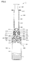
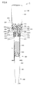
図1は、本発明の実施の形態に係る薬剤投与具の構成要素を示す断面図である。図1を参照して、本実施の形態に係る薬剤投与具について説明する。
FIG. 1 is a cross-sectional view showing components of a drug administration device according to an embodiment of the present invention. With reference to FIG. 1, the drug administration device according to the present embodiment will be described.
図1に示すように、本実施の形態に係る薬剤投与具1は、薬剤容器100、連結器具200、およびプレフィルドシリンジ300を備える。
As shown in FIG. 1, the drug administration device 1 according to the present embodiment includes a drug container 100, a connecting device 200, and a prefilled syringe 300.
薬剤容器100は、内部に薬剤としての乾燥薬剤または液状薬剤を収容する。薬剤容器100は、口部101aを有する容器本体101と、口部101aを封鎖する封鎖部材110とを含む。封鎖部材110は、リング状部材120によって薬剤容器100の先端に固定される。封鎖部材110は、ゴム部材や熱可塑性エラストマー樹脂を採用することができる。
The drug container 100 contains a dry drug or a liquid drug as a drug inside. The medicine container 100 includes a container main body 101 having a mouth portion 101a and a sealing member 110 that seals the mouth portion 101a. The sealing member 110 is fixed to the tip of the drug container 100 by the ring-shaped member 120. The sealing member 110 can employ a rubber member or a thermoplastic elastomer resin.
封鎖部材110の中央部は、薄肉状に形成されている。封鎖部材110の中央部には、後述する連結器具200の穿刺針250を刺通することができる。
The central part of the sealing member 110 is formed in a thin shape. A puncture needle 250 of the connecting device 200 described later can be pierced through the central portion of the sealing member 110.
リング状部材120は、容器本体101の先端部および封鎖部材110を外周側から囲みこれらを一体に締結する。リング状部材120は、封鎖部材110の中央部を露出させる開口部121を有する。
The ring-shaped member 120 surrounds the distal end portion of the container main body 101 and the sealing member 110 from the outer peripheral side, and fastens them together. The ring-shaped member 120 has an opening 121 that exposes the central portion of the sealing member 110.
連結器具200は、薬剤容器100の内部と、プレフィルドシリンジ300の内部とを連通させるためのものである。連結器具200は、筒体201、仕切部230、ノズル挿入部240および穿刺針250を含む。
The connecting device 200 is for communicating the inside of the medicine container 100 with the inside of the prefilled syringe 300. The connecting device 200 includes a cylindrical body 201, a partition part 230, a nozzle insertion part 240 and a puncture needle 250.
筒体201は、後述するプレフィルドシリンジ300のノズル部311および注射針取付部313を受け入れる受入部200aを一端201a側に有するとともに、薬剤容器100に装着可能な挿着部200bを他端201b側に有する。
The cylindrical body 201 has a receiving portion 200a for receiving a nozzle portion 311 and an injection needle mounting portion 313 of a prefilled syringe 300, which will be described later, on one end 201a side, and an insertion portion 200b that can be attached to the drug container 100 on the other end 201b side. Have.
筒体201は、第1筒部210および第2筒部220によって構成されている。第1筒部210および第2筒部220は、共通の中心軸を有する。第1筒部210および第2筒部220は、たとえば射出成形等によって一体に成形されている。
The cylindrical body 201 is composed of a first cylindrical portion 210 and a second cylindrical portion 220. The 1st cylinder part 210 and the 2nd cylinder part 220 have a common central axis. The 1st cylinder part 210 and the 2nd cylinder part 220 are integrally shape | molded by injection molding etc., for example.
第1筒部210の一端側には、突起部213および係止片215が設けられている。突起部213は、第1筒部210の外周面212に設けられている。突起部213は、第1筒部210の外周面から径方向外側に突出する。突起部213は、後述するプレフィルドシリンジ300に設けられた連結器具取付部315の螺旋溝316に係合する。
A protruding portion 213 and a locking piece 215 are provided on one end side of the first tube portion 210. The protruding portion 213 is provided on the outer peripheral surface 212 of the first tube portion 210. The protruding portion 213 protrudes radially outward from the outer peripheral surface of the first tube portion 210. The protruding portion 213 engages with a spiral groove 316 of a connecting device mounting portion 315 provided in a prefilled syringe 300 described later.
係止片215は、第1筒部210の内周面211に設けられている。係止片215は、仕切部230に近づくにつれて筒体201の径方向内側に向かう。係止片215は、たとえば、周方向に90°ピッチで複数設けられている。係止片215の個数および設置位置については、適宜変更することができる。
The locking piece 215 is provided on the inner peripheral surface 211 of the first cylindrical portion 210. The locking piece 215 is directed radially inward of the cylindrical body 201 as it approaches the partition portion 230. For example, a plurality of locking pieces 215 are provided at a 90 ° pitch in the circumferential direction. About the number and the installation position of the locking piece 215, it can change suitably.
係止片215は、プレフィルドシリンジ300を連結器具200から取り外す際に、後述するキャップ部材330を係止し、これを取り外すための部位である。
The locking piece 215 is a part for locking and removing a cap member 330 described later when the prefilled syringe 300 is removed from the connecting device 200.
第2筒部220は、薬剤容器100の口部101aに挿着可能に設けられている。第2筒部220の内径は、口部101aよりもわずかに小さく設けられている。第2筒部220が口部101aに挿入された状態においては、第2筒部220が外側に広げられ、第2筒部220の内周面221が口部101aの外周部を挟み込む。
The second cylinder part 220 is provided so as to be insertable into the mouth part 101a of the medicine container 100. The internal diameter of the 2nd cylinder part 220 is provided slightly smaller than the opening part 101a. In a state where the second cylinder part 220 is inserted into the mouth part 101a, the second cylinder part 220 is spread outward, and the inner peripheral surface 221 of the second cylinder part 220 sandwiches the outer periphery part of the mouth part 101a.
第2筒部220には切欠き部224が設けられている。切欠き部224を設けることにより、第2筒部220が撓み変形しやすくなり、口部101aへの挿着が容易になる。
The notch part 224 is provided in the 2nd cylinder part 220. FIG. By providing the notch portion 224, the second tube portion 220 is easily bent and deformed, and is easily inserted into the mouth portion 101a.
第2筒部220の内周面221は、口部101aの外周に摺動可能に設けられている。第2筒部220が口部101aに挿入された状態において、筒体201を薬剤容器100側へ押し込むことができる。
The inner peripheral surface 221 of the second cylindrical portion 220 is slidably provided on the outer periphery of the mouth portion 101a. In a state where the second cylinder part 220 is inserted into the mouth part 101a, the cylinder body 201 can be pushed into the medicine container 100 side.
仕切部230は、筒体201内部を受入部200a側と挿着部200b側とに仕切る。仕切部230は、円板形状を有する。仕切部230は、中央部に貫通孔230aを有する。
The partition part 230 partitions the inside of the cylinder 201 into the receiving part 200a side and the insertion part 200b side. The partition part 230 has a disk shape. The partition part 230 has the through-hole 230a in the center part.
ノズル挿入部240は、一端201a側に位置する仕切部230の主面230bに設けられている。ノズル挿入部240は、主面230bから筒体201の一端201a側に向けて延在する。ノズル挿入部240は、筒状形状を有する。ノズル挿入部240の内部は貫通孔230aに連通する。ノズル挿入部240には、プレフィルドシリンジ300のノズル部311が液密に挿入される。
The nozzle insertion part 240 is provided in the main surface 230b of the partition part 230 located in the one end 201a side. The nozzle insertion portion 240 extends from the main surface 230b toward the one end 201a of the cylindrical body 201. The nozzle insertion part 240 has a cylindrical shape. The inside of the nozzle insertion portion 240 communicates with the through hole 230a. The nozzle portion 311 of the prefilled syringe 300 is inserted into the nozzle insertion portion 240 in a liquid-tight manner.
穿刺針250は、他端201b側に位置する仕切部230の主面230cに設けられている。穿刺針250は、主面230cから筒体201の他端201b側に向けて延在する。穿刺針250は、貫通孔230aに連通する中空管路250aを有する。穿刺針250は、上述の封鎖部材110を貫通可能に設けられている。
The puncture needle 250 is provided in the main surface 230c of the partition part 230 located in the other end 201b side. The puncture needle 250 extends from the main surface 230c toward the other end 201b of the cylindrical body 201. The puncture needle 250 has a hollow duct 250a communicating with the through hole 230a. The puncture needle 250 is provided so as to be able to penetrate the sealing member 110 described above.
上述の第1筒部210,仕切部230およびノズル挿入部240によって、ノズル部311および注射針取付部313を受け入れる受入部200aが構成されている。ノズル挿入部240の内部にノズル部311が挿入され、ノズル挿入部240と第1筒部210との間の隙間に注射針取付部313が挿入される。
The receiving portion 200a for receiving the nozzle portion 311 and the injection needle mounting portion 313 is constituted by the first tubular portion 210, the partition portion 230, and the nozzle insertion portion 240 described above. The nozzle portion 311 is inserted into the nozzle insertion portion 240, and the injection needle attachment portion 313 is inserted into the gap between the nozzle insertion portion 240 and the first tube portion 210.
ノズル部311がノズル挿入部240に嵌り込み、ノズル部311と注射針取付部313が仕切部230側に向けて押し進めることが困難となることにより、受入部200aにノズル部311および注射針取付部313が受け入れられた状態となる。
The nozzle portion 311 fits into the nozzle insertion portion 240, and it becomes difficult for the nozzle portion 311 and the injection needle attachment portion 313 to be pushed toward the partition portion 230 side, so that the nozzle portion 311 and the injection needle attachment portion are inserted into the receiving portion 200a. 313 is accepted.
上述の第2筒部220によって、薬剤容器100に装着可能な挿着部200bが構成されている。第2筒部220が薬剤容器100に嵌り込み、薬剤容器100側に向けて押し進めることが困難となることにより、挿着部200bに薬剤容器100が挿着された状態となる。
The above-mentioned second cylinder part 220 constitutes an insertion part 200b that can be attached to the medicine container 100. When the second cylinder 220 is fitted into the drug container 100 and it is difficult to push the drug toward the drug container 100, the drug container 100 is inserted into the insertion part 200b.
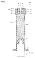
プレフィルドシリンジ300は、筒状容器310、プランジャ320、キャップ部材330、および栓部材340を含む。
The prefilled syringe 300 includes a cylindrical container 310, a plunger 320, a cap member 330, and a plug member 340.
筒状容器310は、先端側に設けられたノズル部311、基端側に設けられたフランジ部312、ノズル部311の外側に設けられた注射針取付部313、当該注射針取付部313の外側に設けられた連結器具取付部315を有する。
The cylindrical container 310 includes a nozzle portion 311 provided on the distal end side, a flange portion 312 provided on the proximal end side, an injection needle attachment portion 313 provided outside the nozzle portion 311, and an outer side of the injection needle attachment portion 313. And a connecting device mounting portion 315 provided in the housing.
ノズル部311は、筒状容器310内に収容された液剤を吐出可能に設けられている。液剤としては、生理食塩水、ブトウ糖液のような溶解液又は薬液を採用することができる。
The nozzle part 311 is provided so that the liquid agent accommodated in the cylindrical container 310 can be discharged. As the liquid agent, a solution or a chemical solution such as physiological saline or butter sugar solution can be adopted.
フランジ部312は、筒状容器310の基端からその径方向外側に向けて突出する。フランジ部312は、人指し指および中指等の指先を引っ掛け可能に構成されている。
The flange portion 312 protrudes from the proximal end of the cylindrical container 310 outward in the radial direction. The flange portion 312 is configured to be able to hook a fingertip such as an index finger and a middle finger.
注射針取付部313は、ノズル部311を取り囲むように設けられている。注射針取付部313は、後述する注射針400(図8参照)を取付けるための部位である。注射針取付部313は、略筒状形状を有する。注射針取付部313の内周面には、案内溝としての螺旋溝314が設けられている。
The injection needle mounting portion 313 is provided so as to surround the nozzle portion 311. The injection needle attachment portion 313 is a part for attaching an injection needle 400 (see FIG. 8) described later. The injection needle mounting portion 313 has a substantially cylindrical shape. A spiral groove 314 as a guide groove is provided on the inner peripheral surface of the injection needle mounting portion 313.
螺旋溝314は、注射針400の基端に設けられた係合突起421(図8参照)に係合する。すなわち、後述する螺旋溝314の谷径L2(図2参照)は、係合突起421の外径よりもわずかに大きい。ここで、螺旋溝314の谷径L2とは、螺旋溝314の底部間の距離である。螺旋溝314は、注射針400を注射針取付部313に取付ける際に注射針400の移動を案内する。
The spiral groove 314 engages with an engagement protrusion 421 (see FIG. 8) provided at the proximal end of the injection needle 400. That is, a valley diameter L2 (see FIG. 2) of a spiral groove 314 described later is slightly larger than the outer diameter of the engagement protrusion 421. Here, the valley diameter L2 of the spiral groove 314 is the distance between the bottoms of the spiral groove 314. The spiral groove 314 guides the movement of the injection needle 400 when the injection needle 400 is attached to the injection needle attachment portion 313.
連結器具取付部315は、注射針取付部313を取り囲むように設けられている。連結器具取付部315は、連結器具200の一端側を取付けるための部位である。連結器具取付部315は、略筒状形状を有する。連結器具取付部315の内周面には、螺旋溝316が設けられている。
The connecting instrument mounting portion 315 is provided so as to surround the injection needle mounting portion 313. The connection tool attachment portion 315 is a part for attaching one end side of the connection tool 200. The connecting instrument mounting portion 315 has a substantially cylindrical shape. A spiral groove 316 is provided on the inner peripheral surface of the connecting device mounting portion 315.
螺旋溝316は、連結器具200の一端部側に設けられた突起部213に係合する。螺旋溝316は、連結器具200を連結器具取付部315に取付ける際に、連結器具200の移動を案内する。
The spiral groove 316 engages with a protrusion 213 provided on one end side of the connecting device 200. The spiral groove 316 guides the movement of the connecting device 200 when the connecting device 200 is attached to the connecting device attaching portion 315.
プランジャ320は、筒状容器310の基端側から挿入される。プランジャ320は、プランジャロッド321と、当該プランジャロッド321の先端に取り付けられたガスケット322を有する。ガスケット322は、筒状容器310の内周面に摺動可能に設けられている。ガスケット322によって、筒状容器310の内部が液密に維持される。
The plunger 320 is inserted from the proximal end side of the cylindrical container 310. The plunger 320 has a plunger rod 321 and a gasket 322 attached to the tip of the plunger rod 321. The gasket 322 is slidably provided on the inner peripheral surface of the cylindrical container 310. The gasket 322 maintains the inside of the cylindrical container 310 liquid-tight.
キャップ部材330は、注射針取付部313の外周側に着脱可能に嵌り込む。キャップ部材330は、天板部331および周壁部332を有する。天板部331は、円板形状を有する。天板部331の略中央部には、円形形状の開口部331aが設けられている。ノズル部311の軸方向から見た場合に、開口部331aは、ノズル部311を露出させる。周壁部332は、筒状に構成され、天板部331の周縁に接続するように設けられている。
The cap member 330 is detachably fitted to the outer peripheral side of the injection needle mounting portion 313. The cap member 330 has a top plate portion 331 and a peripheral wall portion 332. The top plate portion 331 has a disc shape. A circular opening 331a is provided at a substantially central portion of the top plate portion 331. When viewed from the axial direction of the nozzle portion 311, the opening 331 a exposes the nozzle portion 311. The peripheral wall portion 332 is formed in a cylindrical shape and is provided so as to be connected to the peripheral edge of the top plate portion 331.
開口部331aは、注射針400の基端部側を挿入不能に設けられている。具体的には、開口部331aの口径L1(図2参照)は、注射針400の係合突起421の外径よりも小さい。また、開口部331aの口径L1は、螺旋溝314の谷径L2よりも小さい。
The opening 331a is provided so that the proximal end side of the injection needle 400 cannot be inserted. Specifically, the diameter L1 (see FIG. 2) of the opening 331a is smaller than the outer diameter of the engagement protrusion 421 of the injection needle 400. The aperture L1 of the opening 331a is smaller than the valley diameter L2 of the spiral groove 314.
開口部331aの口径L1を係合突起421の外径よりも小さくしつつ、開口部331aの口径L1を螺旋溝314の谷径L2より小さくすることにより、キャップ部材330は、注射針取付部313に嵌り込んだ状態においては、注射針取付部313への注射針400の取付けを不能とする。なお、開口部331aの口径L1を螺旋溝314の内径(山部間の距離)よりも小さくすることにより、注射針取付部313への注射針400の取付けをより確実に不能とすることができる。
By making the diameter L1 of the opening 331a smaller than the outer diameter of the engaging protrusion 421 and making the diameter L1 of the opening 331a smaller than the valley diameter L2 of the spiral groove 314, the cap member 330 can be attached to the injection needle mounting portion 313. In the state where the needle 400 is fitted, the attachment of the injection needle 400 to the injection needle attachment portion 313 is disabled. In addition, by making the diameter L1 of the opening 331a smaller than the inner diameter (distance between the crests) of the spiral groove 314, the attachment of the injection needle 400 to the injection needle attachment portion 313 can be more reliably disabled. .
栓部材340は、ノズル部311に着脱可能に取付けられる。栓部材340は、有底筒状に設けられている。栓部材340は、ノズル部311に取付けられた状態で、ノズル部311を液密に封止する。
The plug member 340 is detachably attached to the nozzle portion 311. The plug member 340 is provided in a bottomed cylindrical shape. The plug member 340 is liquid-tightly sealed with the nozzle portion 311 while being attached to the nozzle portion 311.
ノズル部311の先端に対向する底部と反対側に位置する栓部材340の一端側は、キャップ部材330の開口部331aに挿入可能に設けられている。また、栓部材340の一端側は、ノズル部311の外周面と注射針取付部313の内周面との間の隙間に入り込む。
One end side of the plug member 340 located on the opposite side of the bottom portion facing the tip of the nozzle portion 311 is provided so as to be inserted into the opening 331a of the cap member 330. One end side of the plug member 340 enters a gap between the outer peripheral surface of the nozzle portion 311 and the inner peripheral surface of the injection needle attachment portion 313.
具体的には、栓部材340の一端側の外径は、開口部331aの口径よりも小さくなっている。また、栓部材340の一端側の外径は、螺旋溝314の内径よりも小さくなっている。
Specifically, the outer diameter on one end side of the plug member 340 is smaller than the diameter of the opening 331a. Further, the outer diameter on one end side of the plug member 340 is smaller than the inner diameter of the spiral groove 314.
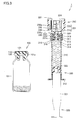
図2は、図1に示す薬剤投与具を使用する際の第1工程を示す断面図であり、プレフィルドシリンジの先端側の拡大図である。図3から図8は、図1に示す薬剤投与具を使用する際の第2工程から第7工程を示す断面図である。図2から図8を参照して、本実施の形態に係る薬剤投与具1を使用する際の動作について説明する。
FIG. 2 is a cross-sectional view showing a first step when using the drug administration device shown in FIG. 1, and is an enlarged view of the front end side of the prefilled syringe. 3 to 8 are cross-sectional views showing the second to seventh steps when using the drug administration device shown in FIG. With reference to FIG. 2 to FIG. 8, the operation when using the drug administration device 1 according to the present embodiment will be described.
薬剤投与具1を使用する際には、まず、内部に薬剤が密閉された薬剤容器100、連結器具200、および内部に液剤が収容されたプレフィルドシリンジ300を個別に準備する。プレフィルドシリンジ300については、キャップ部材330が注射針取付部313の外周側に嵌り込んでいるとともに、ノズル部311が栓部材340によって封止されているものを準備する。
When using the drug administration device 1, first, the drug container 100 in which the drug is sealed, the connecting device 200, and the prefilled syringe 300 in which the liquid drug is stored are prepared separately. About the prefilled syringe 300, while the cap member 330 is fitted in the outer peripheral side of the injection needle attaching part 313, what the nozzle part 311 is sealed with the stopper member 340 is prepared.
次に、図2に示すように、第1工程において、栓部材340をプレフィルドシリンジ300から取り外す。この際、ノズル部311から液剤が外部に漏れないように、ノズル部311を上方に向けた状態で栓部材340を取り外すことが好ましい。
Next, as shown in FIG. 2, the plug member 340 is removed from the prefilled syringe 300 in the first step. At this time, it is preferable to remove the plug member 340 with the nozzle portion 311 facing upward so that the liquid agent does not leak outside from the nozzle portion 311.
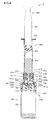
続いて、図3に示すように、第2工程において、ノズル部311を上方に向けた状態で、プレフィルドシリンジ300の先端に連結器具200を取り付ける。具体的には、第1筒部210の外周面に設けられた突起部213を連結器具取付部315の螺旋溝316に噛み合わせて、連結器具200を筒体201の軸周りに回転させる。
Subsequently, as shown in FIG. 3, in the second step, the connecting device 200 is attached to the tip of the prefilled syringe 300 with the nozzle portion 311 facing upward. Specifically, the projection 213 provided on the outer peripheral surface of the first tube portion 210 is engaged with the spiral groove 316 of the connection device mounting portion 315, and the connection device 200 is rotated around the axis of the tube body 201.
螺旋溝316に沿って突起部213を相対的に移動させることにより、ノズル挿入部240が、キャップ部材330の開口部331aを通過して、ノズル部311と注射針取付部313との間の隙間に入り込む。
By relatively moving the protrusion 213 along the spiral groove 316, the nozzle insertion portion 240 passes through the opening 331 a of the cap member 330 and the gap between the nozzle portion 311 and the injection needle attachment portion 313. Get in.
螺旋溝316に沿って突起部213を相対的に前進させながら、筒体201の軸方向に沿ってプレフィルドシリンジ300側に向けて連結器具200を所定の距離進行させることにより、ノズル挿入部240にノズル部311が液密に挿着される。
While the protrusion 213 is relatively advanced along the spiral groove 316, the connecting tool 200 is advanced by a predetermined distance toward the prefilled syringe 300 along the axial direction of the cylindrical body 201. The nozzle portion 311 is inserted in a liquid-tight manner.
互いに対向する係止片215の先端部間の距離は、キャップ部材330の周壁部332の外径よりも小さい。このため、筒体201の軸方向に沿ってプレフィルドシリンジ300側に向けて連結器具200を進行させて行く際には、係止片215は、キャップ部材330によって押し広げられる。キャップ部材330全体が相対的に係止片215を通過した後には、係止片215は、元の形状に戻る。これにより、係止片215はキャップ部材330の基端側に係止可能となる。
The distance between the tip portions of the locking pieces 215 facing each other is smaller than the outer diameter of the peripheral wall portion 332 of the cap member 330. For this reason, when the connecting device 200 is advanced toward the prefilled syringe 300 along the axial direction of the cylindrical body 201, the locking piece 215 is pushed and spread by the cap member 330. After the entire cap member 330 has relatively passed through the locking piece 215, the locking piece 215 returns to its original shape. Thereby, the locking piece 215 can be locked to the proximal end side of the cap member 330.
続いて、図4に示すように、第3工程において、連結器具200の第2筒部220を薬剤容器100の口部101aに嵌め込み、連結器具200を薬剤容器100側に向けて押し込むことにより、穿刺針250を薬剤容器100の封鎖部材110に刺通させる。これにより、穿刺針250の中空管路250aを介してプレフィルドシリンジ300の内部と薬剤容器100の内部とが連通する。このように連結器具200は、受入部200aにノズル部311および注射針取付部313が受け入れられた状態かつ挿着部200bに薬剤容器100が挿着された状態で筒状容器310の内部と薬剤容器100の内部とを連通させる。
Subsequently, as shown in FIG. 4, in the third step, by fitting the second cylindrical portion 220 of the connecting device 200 into the mouth portion 101a of the drug container 100 and pushing the connecting device 200 toward the drug container 100 side, The puncture needle 250 is pierced through the sealing member 110 of the drug container 100. As a result, the inside of the prefilled syringe 300 and the inside of the drug container 100 communicate with each other through the hollow conduit 250 a of the puncture needle 250. As described above, the connecting device 200 includes the inside of the cylindrical container 310 and the medicine in a state where the nozzle part 311 and the injection needle attachment part 313 are received in the receiving part 200a and the medicine container 100 is inserted in the insertion part 200b. The inside of the container 100 is communicated.
なお、連結器具200を安定して押し込むために、プレフィルドシリンジ300のノズル部311を下方に向け、第2筒部220の下方に薬剤容器100が位置する状態で、連結器具200を下方に向けて押し込むことが好ましい。
In addition, in order to push the connecting instrument 200 stably, the nozzle part 311 of the prefilled syringe 300 is directed downward, and the connecting instrument 200 is directed downward in a state where the drug container 100 is positioned below the second cylindrical part 220. It is preferable to push in.
次に、図5に示すように、第4工程において、プランジャ320を薬剤容器100側に向けて押し込むことにより、プレフィルドシリンジ300内に収容された液剤を、ノズル部311、貫通孔230aおよび穿刺針250の中空管路250aを介して、薬剤容器100の内部に移動させる。薬剤容器100の内部にて、薬剤と液剤とを混合して、薬剤Lを調製する。
Next, as shown in FIG. 5, in the fourth step, the plunger 320 is pushed toward the drug container 100, so that the liquid stored in the prefilled syringe 300 is discharged into the nozzle portion 311, the through-hole 230 a and the puncture needle. It moves to the inside of the medicine container 100 through the 250 hollow pipes 250a. The drug L is prepared by mixing the drug and the liquid in the drug container 100.
続いて、図6に示すように、第5工程において、薬剤容器100とプレフィルドシリンジ300とが連結器具200によって連結された状態で、ノズル部311を上方に向けてプランジャ320を筒状容器310の基端部側へ後退させる。プランジャ320を後退させることにより、薬剤容器100内で調製された薬剤Lをプレフィルドシリンジ300内に吸引する。
Subsequently, as shown in FIG. 6, in the fifth step, in the state where the drug container 100 and the prefilled syringe 300 are connected by the connecting device 200, the plunger 320 is moved upward of the cylindrical container 310 with the nozzle portion 311 facing upward. Retreat to the base end side. By retracting the plunger 320, the drug L prepared in the drug container 100 is sucked into the prefilled syringe 300.
次に、図7に示すように、第6工程において、連結器具200からプレフィルドシリンジ300を取り外す。具体的には、ノズル部311を上方に向けた状態で連結器具200を筒体201の軸周りに回転させる。この際、第2工程における回転方向とは逆方向に連結器具200を回転させる。
Next, as shown in FIG. 7, in the sixth step, the prefilled syringe 300 is removed from the connecting device 200. Specifically, the connecting device 200 is rotated around the axis of the cylinder 201 with the nozzle portion 311 facing upward. At this time, the connecting device 200 is rotated in the direction opposite to the rotation direction in the second step.
螺旋溝316に沿って突起部213を相対的に後退させることにより、連結器具200がプレフィルドシリンジ300から離れる方向に移動する。この際、ノズル挿入部240がキャップ部材330の開口部331aを通ってノズル部311から離間する。これにより、ノズル挿入部240からノズル部311が抜去される。
The connecting device 200 moves in a direction away from the prefilled syringe 300 by relatively retracting the protrusion 213 along the spiral groove 316. At this time, the nozzle insertion portion 240 is separated from the nozzle portion 311 through the opening 331 a of the cap member 330. Thereby, the nozzle part 311 is extracted from the nozzle insertion part 240.
連結器具200がプレフィルドシリンジ300から離れる方向に移動する際には、係止片215はキャップ部材330の基端側の端部に係止する。このため、連結器具200が移動する際に、注射針取付部313は、キャップ部材330に対して相対的に後退することとなる。注射針取付部313が、キャップ部材330に対して所定の距離相対的に後退することにより、キャップ部材330が注射針取付部313から取り外される。取り外されたキャップ部材330は、ノズル挿入部240と第1筒部210との間の隙間に収容される。
When the connecting device 200 moves in a direction away from the prefilled syringe 300, the locking piece 215 is locked to the proximal end of the cap member 330. For this reason, when the connecting device 200 moves, the injection needle mounting portion 313 moves backward relative to the cap member 330. The cap member 330 is removed from the syringe needle mounting portion 313 by the syringe needle mounting portion 313 moving backward relative to the cap member 330 by a predetermined distance. The removed cap member 330 is accommodated in a gap between the nozzle insertion portion 240 and the first tube portion 210.
このように、キャップ部材330が注射針取付部313から取り外された状態で、連結器具200からプレフィルドシリンジ300が取り外される。キャップ部材330が外されることにより、注射針取付部313に注射針400が取り付け可能となる。
In this way, the prefilled syringe 300 is removed from the connecting device 200 in a state where the cap member 330 is removed from the injection needle mounting portion 313. By removing the cap member 330, the injection needle 400 can be attached to the injection needle attachment portion 313.
続いて、図8に示すように、第7工程において、注射針400を注射針取付部313に取付ける。注射針400は、針管410と針基420とを含む。針基420の基端には、径方向外側に突出する係合突起421を有する。係合突起421は、注射針取付部313の螺旋溝314に係合可能に設けられている。
Subsequently, as shown in FIG. 8, in the seventh step, the injection needle 400 is attached to the injection needle attachment portion 313. The injection needle 400 includes a needle tube 410 and a needle base 420. The proximal end of the needle base 420 has an engaging protrusion 421 that protrudes radially outward. The engagement protrusion 421 is provided so as to be engageable with the spiral groove 314 of the injection needle mounting portion 313.
係合突起421を螺旋溝314に噛み合わせて、注射針400を軸周りに回転させることにより、注射針400を注射針取付部313に取付けることができる。
By engaging the engagement protrusion 421 with the spiral groove 314 and rotating the injection needle 400 around the axis, the injection needle 400 can be attached to the injection needle attachment portion 313.
上述のように、本実施の形態に係る薬剤投与具1にあっては、プレフィルドシリンジ300の注射針取付部313にキャップ部材330を取付けることにより、注射針取付部313への注射針400の取付けを不能とすることができる。キャップ部材330は、中央部に開口部331aを有する天板部331と、当該天板部331の周縁に接続される筒状の周壁部332とによって構成されている。このため、キャップ部材330の構成を簡素化することができ、ひいては薬剤投与具1の構成を簡素化することができる。
As described above, in the drug administration device 1 according to the present embodiment, by attaching the cap member 330 to the injection needle attachment portion 313 of the prefilled syringe 300, the injection needle 400 is attached to the injection needle attachment portion 313. Can be disabled. The cap member 330 includes a top plate portion 331 having an opening 331 a at the center portion, and a cylindrical peripheral wall portion 332 connected to the periphery of the top plate portion 331. For this reason, the configuration of the cap member 330 can be simplified, and as a result, the configuration of the drug administration device 1 can be simplified.
また、薬剤投与具1にあっては、連結器具200を用いて薬剤容器100の内部とプレフィルドシリンジ300の内部とを連結させ、薬剤容器100内の薬剤とプレフィルドシリンジ300内の液剤とを混合して薬剤Lの調製が完了するまでは、キャップ部材330が注射針取付部313に取付けられた状態が維持される。
Moreover, in the medicine administration tool 1, the inside of the medicine container 100 and the inside of the prefilled syringe 300 are connected using the connecting device 200, and the medicine in the medicine container 100 and the liquid medicine in the prefilled syringe 300 are mixed. Until the preparation of the medicine L is completed, the state where the cap member 330 is attached to the injection needle attaching portion 313 is maintained.
薬剤Lの調製完了後に、注射針取付部313からキャップ部材330を取り外し可能な状態となるため、使用者が、薬剤の調製前に誤って注射針400を注射針取付部313に取り付けることを防止することができる。
After the preparation of the medicine L is completed, the cap member 330 can be removed from the injection needle mounting portion 313, so that the user is prevented from accidentally attaching the injection needle 400 to the injection needle mounting portion 313 before the preparation of the medicine. can do.
また、使用者は、キャップ部材330が取り外されるまでに、上述の第1工程から第6工程の動作を順次実施しなければならず、手順を意識しながら注射針の取付けを行なうようになる。この点によっても薬剤Lの調製前に誤って注射針400を注射針取付部313に取り付けることを防止することができる。
Also, the user must sequentially perform the operations from the first step to the sixth step until the cap member 330 is removed, and attaches the injection needle while being aware of the procedure. This can also prevent the injection needle 400 from being erroneously attached to the injection needle attachment portion 313 before the preparation of the medicine L.
さらに、係止片215によってキャップ部材330を係止し、連結器具200からプレフィルドシリンジ300を取り外す際に、キャップ部材330が注射針取付部313から取り外されることにより、使用者がキャップ部材330を直接取り外すことが不要となる。これにより、使用者の手間を省くことが可能となる。
Further, when the cap member 330 is locked by the locking piece 215 and the prefilled syringe 300 is removed from the connecting device 200, the cap member 330 is removed from the injection needle mounting portion 313, so that the user directly holds the cap member 330. It becomes unnecessary to remove. Thereby, it becomes possible to save a user's effort.
連結器具200は、第1筒部210と第2筒部220とによって構成される筒体201を仕切部230によって軸方向に2つに分割した構成である。また、連結器具200は、第1筒部210側に筒状のノズル挿入部240を設けるとともに、第2筒部220側に穿刺針を設けた構成である。
The connecting device 200 has a configuration in which a cylindrical body 201 constituted by a first cylindrical portion 210 and a second cylindrical portion 220 is divided into two in the axial direction by a partitioning portion 230. The connecting device 200 has a configuration in which a cylindrical nozzle insertion portion 240 is provided on the first cylindrical portion 210 side and a puncture needle is provided on the second cylindrical portion 220 side.
このように連結器具200を構成することにより、第1筒部210側にプレフィルドシリンジ300を挿入するとともに、第2筒部220側に薬剤容器100を挿入した後に、筒体201を薬剤容器100に向けて押し込むことにより、穿刺針を薬剤容器100の封鎖部材110に刺通させることができる。このため、第1筒部210と第2筒部220を相対的に移動させるようなスライド機構を設ける必要がなく、連結器具200の構成を簡素化することができ、ひいては薬剤投与具1の構成を簡素化することができる。
By configuring the connecting device 200 in this manner, the prefilled syringe 300 is inserted into the first tube portion 210 side, and the drug container 100 is inserted into the second tube portion 220 side, and then the tube body 201 is inserted into the drug container 100. By pushing inward, the puncture needle can be pierced through the sealing member 110 of the drug container 100. For this reason, it is not necessary to provide a slide mechanism that relatively moves the first tube portion 210 and the second tube portion 220, the configuration of the connecting device 200 can be simplified, and consequently the configuration of the drug administration device 1 Can be simplified.
以上のように、本実施の形態に係る薬剤投与具1およびプレフィルドシリンジ300は、簡素な構成を有し、これらを用いることにより、薬剤調製前のプレフィルドシリンジ300に注射針400が誤って取付けられることを防止することができる。
As described above, the drug administration device 1 and the prefilled syringe 300 according to the present embodiment have a simple configuration, and by using these, the injection needle 400 is erroneously attached to the prefilled syringe 300 before drug preparation. This can be prevented.
上述した実施の形態においては、筒体201に係止片215が設けられる場合を例示して説明したが、これに限定されず、係止片215が設けられていなくてもよい。
In the above-described embodiment, the case where the locking piece 215 is provided on the cylinder 201 has been described as an example. However, the present invention is not limited to this, and the locking piece 215 may not be provided.
この場合においては、薬剤を調製後に連結器具200からプレフィルドシリンジ300を取り外した際には、キャップ部材330は注射針取付部313に嵌り込んだままである。このため、キャップ部材330を使用者が注射針取付部313から取り外した後に、注射針400を注射針取付部313に取り付ける。
In this case, when the prefilled syringe 300 is removed from the coupling device 200 after the preparation of the medicine, the cap member 330 remains fitted in the injection needle mounting portion 313. For this reason, after the user removes the cap member 330 from the injection needle attachment portion 313, the injection needle 400 is attached to the injection needle attachment portion 313.
上述した実施の形態においては、キャップ部材330の開口部331aが円形形状である場合を例示して説明したが、これに限定されず、ノズル挿入部240を挿入可能に構成され、注射針400の基端側を挿入不能に構成される限り、多角形形状、楕円形状等であってもよい。
In the above-described embodiment, the case where the opening 331a of the cap member 330 has a circular shape has been described as an example. However, the present invention is not limited thereto, and the nozzle insertion portion 240 can be inserted. A polygonal shape, an elliptical shape, or the like may be used as long as the base end side is configured so as not to be inserted.
また、上述した実施の形態においては、キャップ部材330が注射針取付部313の外周側に嵌り込んだ状態において、ノズル部311の軸方向から見た場合に、キャップ部材330の開口部331aの縁の全てが、注射針取付部313の内周面に設けられた螺旋溝314の谷径よりも内側に位置する場合を例示して説明したがこれに限定されず、ノズル挿入部240を挿入可能に構成され、注射針400の基端側を挿入不能に構成される限り、開口部331aの縁の少なくとも一部が螺旋溝314の谷径よりも内側に位置していればよい。たとえば、開口部331aの縁の少なくとも一部から径方向内側に向けて突出する突出部がキャップ部材330に設けられていてもよい。
In the above-described embodiment, the edge of the opening 331a of the cap member 330 is seen when viewed from the axial direction of the nozzle portion 311 in a state where the cap member 330 is fitted on the outer peripheral side of the injection needle mounting portion 313. In the above description, the case where all of these are located inside the valley diameter of the spiral groove 314 provided on the inner peripheral surface of the injection needle mounting portion 313 is illustrated, but the present invention is not limited thereto, and the nozzle insertion portion 240 can be inserted. As long as the base end side of the injection needle 400 is configured so as not to be inserted, at least a part of the edge of the opening 331a only needs to be located inside the valley diameter of the spiral groove 314. For example, the cap member 330 may be provided with a protruding portion that protrudes radially inward from at least a part of the edge of the opening 331a.
また、上述した実施の形態においては、注射針取付部313の内周面に設けられた案内溝が螺旋溝314である場合を例示して説明したが、これに限定されず、注射針を取付け可能に構成される限り適宜変更することができる。
In the above-described embodiment, the case where the guide groove provided on the inner peripheral surface of the injection needle attachment portion 313 is the spiral groove 314 has been described as an example. However, the present invention is not limited thereto, and the injection needle is attached. As long as it can be configured, it can be changed as appropriate.
以上、本発明の実施の形態について説明したが、今回開示された実施の形態はすべての点で例示であって制限的なものではない。本発明の範囲は請求の範囲によって示され、請求の範囲と均等の意味および範囲内でのすべての変更が含まれる。
As mentioned above, although embodiment of this invention was described, embodiment disclosed this time is an illustration and restrictive at no points. The scope of the present invention is defined by the terms of the claims, and includes meanings equivalent to the terms of the claims and all changes within the scope.