WO2016181693A1 - 電力量演算システム - Google Patents
電力量演算システム Download PDFInfo
- Publication number
- WO2016181693A1 WO2016181693A1 PCT/JP2016/056869 JP2016056869W WO2016181693A1 WO 2016181693 A1 WO2016181693 A1 WO 2016181693A1 JP 2016056869 W JP2016056869 W JP 2016056869W WO 2016181693 A1 WO2016181693 A1 WO 2016181693A1
- Authority
- WO
- WIPO (PCT)
- Prior art keywords
- watt
- power
- hour meter
- electric energy
- meter
- Prior art date
- Legal status (The legal status is an assumption and is not a legal conclusion. Google has not performed a legal analysis and makes no representation as to the accuracy of the status listed.)
- Ceased
Links
Images



Classifications
-
- G—PHYSICS
- G01—MEASURING; TESTING
- G01R—MEASURING ELECTRIC VARIABLES; MEASURING MAGNETIC VARIABLES
- G01R11/00—Electromechanical arrangements for measuring time integral of electric power or current, e.g. of consumption
- G01R11/02—Constructional details
- G01R11/24—Arrangements for avoiding or indicating fraudulent use
-
- G—PHYSICS
- G01—MEASURING; TESTING
- G01R—MEASURING ELECTRIC VARIABLES; MEASURING MAGNETIC VARIABLES
- G01R21/00—Arrangements for measuring electric power or power factor
-
- G—PHYSICS
- G01—MEASURING; TESTING
- G01R—MEASURING ELECTRIC VARIABLES; MEASURING MAGNETIC VARIABLES
- G01R35/00—Testing or calibrating of apparatus covered by the other groups of this subclass
Definitions
- the present invention relates to a power amount calculation system that calculates a statistical value (for example, sum) of power consumption in the distribution area using each watt hour meter installed in the distribution area to which power is supplied by an electric power company.
- Patent Document 1 there has been an unauthorized person who steals power (steals power) by performing an illegal act on a watt-hour meter.
- a smart meter is a device that measures and outputs (displays or transmits) the amount of power used in a digital manner, and includes at least a current sensor, a display unit, and a processor.
- the processor measures the amount of power supplied to the supply target (the amount of power used) based on the output of the current sensor, and displays (outputs) the amount of power used by controlling the display unit. It has become.
- the current sensor stops outputting the amount of current, and the processor In some cases, the amount of power used cannot be measured (however, when the generation of magnetism is stopped, the current sensor returns to a normal state and outputs the amount of current, allowing the processor to measure the amount of power used).
- an unauthorized person may perform power theft by temporarily stopping the measurement of electric energy by generating magnetism temporarily with a magnetic generator in the vicinity of the smart meter.
- Such power theft due to magnetism does not involve destruction or remodeling, so it is often not revealed if it is performed temporarily or intermittently rather than constantly.
- the evidence of fraud can be collected.
- a sensor for detecting fraud without destruction / modification is attached to a watt-hour meter (smart meter)
- the evidence of fraud can be collected.
- a magnetic sensor for detecting magnetism is attached to a watt hour meter and threshold processing is performed on the sensor value of the magnetic sensor, it is possible to determine whether or not there is an illegal act due to magnetism, and the log of the determination result can be the evidence described above.
- the electric power company that manages the watt-hour meter sums up the total amount of power used collected from each watt-hour meter in the distribution area (total sum) in order to adjust the power generation amount of the power plant appropriately (power generation amount ⁇ used power amount). ) Determines the appropriate power generation amount.
- the present invention has been made in view of the above problems, and an object thereof is to provide an electric energy calculation system capable of reducing energy loss in power generation of an electric power company.
- the present invention provides a power amount calculation including a group consisting of a plurality of watt-hour meters and a terminal device for obtaining a statistical value of power consumption measured in each watt-hour meter belonging to the group.
- the watt-hour meter includes a watt-hour meter that measures the amount of power used, and a sensor that outputs a sensor value used to detect fraud, and the electric power in which the fraud is detected.
- the terminal device uses the watt hour meter used for the unauthorized watt hour meter.
- an arithmetic processing unit for obtaining the statistical value by correcting the amount of power used.
- the present invention makes it possible to reduce the amount of extra power generation for suppressing power outages as compared with the conventional case, and has the effect of reducing the energy loss of power generation by an electric power company.
- FIG. 1 It is a block diagram which shows schematic structure of the watt-hour meter which concerns on one Embodiment of this invention. It is a block diagram which shows schematic structure of the security sensor shown in FIG. It is a figure which shows the external appearance of the security sensor shown in FIG. It is a flowchart which shows the flow of a process of the watt-hour meter shown in FIG. It is a figure which shows schematic structure of the electric energy calculation system of this embodiment. It is the figure which showed the sum total of the measured value when there is no theft and the total sum of the actual usage, and the sum of the measurement value when there is theft and the total of the actual usage. It is the flowchart which showed the flow of the process which calculates
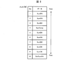
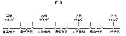
- FIG. 6 is a diagram schematically showing a table stored in a third storage unit shown in FIG. 5 and accumulating the sum of used electric energy A (SumEN, SumTemp). It is the figure which showed typically the period when a fraudulent person makes an electricity meter into an abnormal state by cheating.
- the watt-hour meter of the present embodiment is a so-called smart meter, and the main forms of theft are (1) stealing that reduces the function of the current sensor of the watt-hour meter by magnetic emission, and (2) radio wave emission or electrostatic discharge. There is power theft that causes the processor to hang by (ESD).
- ⁇ Theft by magnetic discharge is as described in the background art. That is, in the watt-hour meter, the processor measures the amount of power used by using the sensor value of the current sensor, but an unauthorized person can generate powerful magnetism in the vicinity of the watt-hour meter, By degrading the function of the current sensor and making it impossible to output the amount of current, it is impossible to measure the amount of power used and steal power (However, if the generation of magnetism is stopped, the current sensor returns to the normal state and the amount of current is And the processor can measure the amount of power used).
- Thefts due to radio wave emission or electrostatic discharge are as follows.
- the processor of the watt hour meter is configured to display (output) the used electric energy by controlling the display unit in addition to measuring the used electric energy based on the current sensor. Therefore, the processor transmits / receives a signal to / from the display unit.
- the display unit since the display unit needs to be visible from the outside, it is not protected by an electromagnetic shield. Therefore, although the watt-hour processor itself is protected by an electromagnetic shield, it emits radio waves or discharges electrostatically due to the fact that it transmits and receives signals to and from a display unit that has a large surface area and is not protected by an electromagnetic shield. Low resistance to (ESD).
- the unauthorized person temporarily emits radio waves or discharges electrostatically to hang up the watt-hour processor temporarily.
- the amount of power used is not measured even if power is supplied, so it is possible to steal power (when the emission of radio waves or electrostatic discharge is stopped, the processor The power consumption can be measured after returning to the normal state).
- the watt-hour meter is connected to a terminal device of an electric power company via a communication network, and periodically transmits data indicating the amount of power used to the terminal device (for example, every 15 minutes).
- the processor In addition, if the processor continues to hang up due to radio wave emission (or electrostatic discharge) for at least a long period exceeding the length of the transmission cycle, the processor itself that controls the communication process cannot control the communication process in the first place. Even if it becomes the transmission timing of the data to show, the said data are not transmitted to the terminal device of an electric power company, and a power theft will be exposed immediately.
- an unauthorized person does not always set the watt-hour meter in an abnormal state (function deterioration of the current sensor or hang-up of the processor), but transmits data indicating the amount of power used as shown in FIG.
- the watt hour meter is normally operated in the other periods. Specifically, an unauthorized person steals power as follows.
- An unauthorized person installs a magnetic generator, a radio wave generator, or an electrostatic discharge device used for theft in the vicinity of the watt-hour meter that is the target of theft.
- the magnetism generator includes an antenna, a processor, and a magnetism generator (for example, an electromagnet) that generates magnetism by being controlled by the processor.
- the antenna detects the radio wave generated by the transmission process when the watt-hour meter performs the transmission process via the communication network. (If the communication network is a wireless communication network, the antenna detects the radio wave generated by the wireless communication. When the network is wired (for example, PLC), leaked radio waves from the wired are detected).
- the processor determines a transmission cycle of transmission processing (transmission of data indicating the amount of power) that is periodically performed with reference to the detection result of the antenna.
- the processor applies magnetism to the magnetism generation unit only during a part of the period between the transmission timing of the data indicating the amount of power used and the next transmission timing and spaced from both transmission timings. In other periods, the generation of magnetism is stopped in the magnetism generation unit. As a result, the function of the current sensor is reduced by magnetism during the abnormal state period shown in FIG. 9 to make it impossible to measure the electric energy, while the electric energy is measured because no magnetism is generated during the normal period. Become. Therefore, the amount of power used for data transmitted in the transmission process is unlikely to be zero, and it is difficult to expose theft.
- the radio wave generator includes an antenna, a processor, and a radio wave generator that generates radio waves under the control of the processor.
- the antenna of the radio wave generator has the same function as the antenna of the magnetic generator.
- the processor of the radio wave generator determines the transmission cycle in the same manner as the processor of the magnetic generator. Then, the processor of the radio wave generator generates radio waves only during a part of the period between the transmission timing and the next transmission timing of the data indicating the power consumption based on the transmission cycle.
- the radio wave is generated in the unit, and in other periods, the radio wave generation unit stops generating the radio wave. Accordingly, the watt-hour processor is hung up by radio waves during the abnormal state period shown in FIG.
- the electrostatic discharge device includes an antenna, a processor, and an electrostatic discharge unit that discharges static electricity by being controlled by the processor.
- the antenna of the electrostatic discharge device has the same function as the antenna of the magnetic generator.
- the processor of the electrostatic discharge device determines the transmission cycle in the same manner as the processor of the magnetic generator. Then, the processor of the electrostatic discharge device performs electrostatic discharge only during a part of the period between the transmission timing and the next transmission timing of the data indicating the power consumption based on the transmission cycle. Static electricity is generated in the part, and electrostatic discharge is stopped in the electrostatic discharge part in other periods. As a result, during the abnormal state shown in FIG.
- the watt-hour processor is hung up by electrostatic discharge to disable the measurement of the electric energy, while during the normal state, the electric energy is measured to stop the electrostatic discharge. Will be. Further, the transmission timing is included in the normal period. Therefore, the amount of power used for the data transmitted in the transmission process is unlikely to become zero, and the periodic transmission process is also performed normally, so that it is difficult to reveal theft.
- Unauthorized persons use the magnetic generators, radio wave generators, or electrostatic discharge devices as described above to display data that shows less power consumption (but not zero) than actual usage. Can be transmitted periodically to the power company, and while revealing theft, the exposure of theft is suppressed.
- the watt-hour meter of one embodiment of the present invention a fraudulent act using the above magnetic generator, radio wave generator, or electrostatic discharge device (fraud for stealing) is detected. It has a function of transmitting a fraud log indicating that a fraudulent act for stealing has been performed to a terminal device of a power company.
- the watt-hour meter of this embodiment will be described.
- a watt-hour meter 100 is a smart meter that measures the amount of power supplied to a measurement target (for example, a house) via a three-phase AC transmission line P1 to P3 by a digital method. is there.
- the watt-hour meter 100 includes current sensors CT1 and CT3, a voltage dividing circuit 102, a power supply circuit 103, a display unit 104, an external communication unit 105, an RTC 106, and a first storage unit. 107, a first control device 108, and a security sensor 109.
- the current sensor CT1 is a sensor that detects the current value IP1 of the power transmission line P1
- the current sensor CT3 is a sensor that detects the current value IP3 of the power transmission line P3.
- the voltage dividing circuit 102 is a sensor that detects a voltage value VP1 of the transmission line P1 and a voltage value VP3 of P3 of the transmission line.
- the power supply circuit 103 is a power supply that supplies power to each hardware included in the watt-hour meter 100.
- the display unit 104 is a display device that is electrically connected directly to the first control device 108 and displays and outputs the amount of power used by being controlled by the first control device 108.
- a liquid crystal display device is used as the display unit 104.
- the display unit 104 is attached to the watt hour meter 100 so as to be visible from the outside of the watt hour meter 100. This is to make the power user visually recognize the content displayed on the display unit 104.
- the external communication unit 105 is a communication port for communicating with the power company terminal device 600 via the communication network 500 shown in FIG.
- Communication network 500 may be a wireless communication network (for example, wireless LAN) or a wired communication network (for example, PLC (power line carrier)).
- the first storage unit 107 is a storage area for storing information.
- an EEPROM registered trademark; Electrically Erasable Programmable Read-Only Memory
- storage part 107 is performed by the 1st control apparatus 108.
- FIG. 1st control apparatus 108 FIG.
- the first control device 108 is a control circuit board that controls each hardware of the watt-hour meter 100. Specifically, a processor (for example, a CPU (Central Processing Unit)) that executes processing according to a program is used.
- a processor for example, a CPU (Central Processing Unit)
- CPU Central Processing Unit
- the first control device 108 includes a watt-hour meter side unit 111, a display control unit 112, an unauthorized log acquisition unit 113, and an external communication control unit 114.
- the first control device 108 is hardware, but the blocks 111 to 114 included in the first control device 108 are functional blocks that indicate software functions executed by the first control device 108.
- the watt-hour meter side unit 111 uses the detection values of the current sensors CT1 and CT3 and the voltage dividing circuit 102 to supply the amount of power supplied to the power supply target via the transmission lines P1 to P3 (the power supply target It is a block that performs processing for calculating (measuring power consumption).
- the watt-hour meter side unit 111 multiplies the current value IP1 and the voltage value VP1 to obtain the instantaneous power value of the transmission line P1, and multiplies the current value IP3 and the voltage value VP3 to instantaneously transmit the transmission line P3.
- the power value is obtained, and the sum of the instantaneous power value of the transmission line P1 and the instantaneous power value of the transmission line P3 is integrated over time, so that the power consumption for the first predetermined time (for example, several seconds) (referred to as power consumption B). Seeking.
- the watt-hour meter side unit 111 uses the power consumption for the second predetermined time (referred to as power consumption A) every time a second predetermined time (15 minutes in the present embodiment) longer than the first predetermined time passes. And the power consumption A is stored in the first storage unit 107. Specifically, when the second predetermined time has elapsed since the last storage of the data indicating the power consumption A, the watt-hour meter side unit 111 obtains between the current time and a time point that is a second predetermined time back from the current time. The integrated value of the used electric energy B is obtained as the used electric energy A, and the obtained used electric energy A is stored in the first storage unit 107.
- the watt-hour meter side unit 111 may obtain the daily power consumption and the monthly power consumption and store them in the first storage unit 107.
- the display control unit 112 is a block that controls the display unit 104.
- the display control unit 112 acquires the power consumption B from the power meter side 111 each time the power meter side unit 111 calculates the power consumption B, and causes the display unit 104 to display the power consumption B.
- the display control unit 112 uses the power consumption A (15 minutes of power consumption) and the daily power stored in the first storage unit 107 in accordance with an externally input command (operator command). Either the amount or the amount of electric power per month may be displayed on the display unit 104.
- the fraud log acquisition unit 113 acquires a fraud log (described in detail later) generated by the security sensor 109 from the security sensor 109, and performs processing to save the fraud log in the first storage unit 107. Specifically, the fraud log acquisition unit 113, when the watt-hour meter side unit 111 performs the calculation process of the power consumption A, within the power usage period in which the fraud time corresponds to the power consumption A (this embodiment) Then, a request command for an unauthorized log that is between the calculation time of the power consumption A and a point that is a second predetermined time after the calculation time) is transmitted to the security sensor 109.
- a fraud log (described in detail later) generated by the security sensor 109 from the security sensor 109, and performs processing to save the fraud log in the first storage unit 107.
- the fraud log acquisition unit 113 when the watt-hour meter side unit 111 performs the calculation process of the power consumption A, within the power usage period in which the fraud time corresponds to the power consumption A (this embodiment) Then
- the security sensor 109 transmits the unauthorized log to the unauthorized log acquisition unit 113, and the unauthorized log acquisition unit 113. Stores the fraud log sent from the security sensor 109 in the first storage unit 107.
- the external communication control unit (communication processing unit) 114 controls the external communication unit 105 every time the watt-hour meter side unit 111 obtains the used power amount A, and displays the power amount information indicating the used power amount A. Processing to transmit to the company terminal device 600 (see FIG. 5) is performed.
- the external communication control unit 114 acquires the fraud log whose fraud time is within the power usage period corresponding to the power consumption A to be transmitted to the fraud log acquisition unit 113 and stores it in the first storage unit 107. If stored, the power amount information indicating the used power amount A and the fraud log is transmitted to the terminal device 600 of the power company.
- the RTC 106 is a real-time clock that outputs time information indicating the current time including the date and time and the hour, minute, and second. Note that the RTC 106 is always connected with a backup battery (not shown), and therefore does not stop due to a power failure or the like, and always outputs accurate time information.
- the first controller 108 recognizes the current time based on the time information of the RTC 106.
- a second control device 207 (see FIG. 2) of the security sensor 109, which will be described later, acquires time information of the RTC 106 from the first control device 108 when the security sensor 109 is activated, and the acquired current time is a timer (not shown). The current time is recognized based on this timer.
- FIG. 2 is a block diagram showing hardware included in the security sensor 109 shown in FIG.
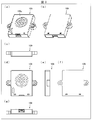
- FIG. 3 is an external view of the security sensor 109.
- FIG. 3A is a perspective view showing the front of the security sensor 109.
- FIG. 3B is a perspective view showing the back surface of the security sensor 109.
- FIG. 3C is a top view of the security sensor 109.
- FIG. 3D is a front view of the security sensor 109.
- FIG. 3E is a side view of the security sensor 109.
- FIG. 3F is a rear view of the security sensor 109.
- FIG. 3G is a bottom view of the security sensor 109.
- the security sensor 109 is a detection device for detecting fraudulent acts on the watt-hour meter 100 (fraud for stealing electric power), and is installed inside the watt-hour meter 100.
- the security sensor 109 is detachable from the watt hour meter 100.
- the security sensor 109 includes a radio wave sensor 201, an electrostatic sensor (sensor) 202, a magnetic sensor 203, a second storage unit 206, and a second control device 207.
- the security sensor 109 has a resin package (housing) 109a shown in FIG. 3A, and the package 109a accommodates the members 201 to 203, 206, and 207 shown in FIG. .
- the radio wave sensor (sensor) 201 is a sensor that outputs a sensor value AD1 that correlates with the amount of radio waves in a frequency band that causes radio wave interference (EMI) to an electronic device. Specifically, when radio wave emission is performed to hang up the processor that measures the amount of power used (the first control device 108 in the present embodiment), the sensor value AD1 output from the radio wave sensor 201 increases. If the first control device 108 hangs up due to radio wave emission, the first control device 108 cannot measure the amount of power used, resulting in theft of power.
- EMI radio wave interference
- the electrostatic sensor (ESD Surge sensor) 202 is a sensor that outputs a sensor value AD2 corresponding to an increase in charge when a charge surge phenomenon occurs in the watt-hour meter 100. Specifically, when electrostatic discharge is performed to hang up a processor (first control device 108 in the present embodiment) that measures electric energy, a charge surge phenomenon occurs in the watt-hour meter 100, and the sensor value AD2 increases. Note that if the first control device 108 hangs up due to electrostatic discharge, the first control device 108 cannot measure the amount of electric power, resulting in theft of electricity.
- the magnetic sensor (sensor) 203 is a sensor that outputs a sensor value AD3 correlated with the magnitude of the magnetic field. Specifically, when magnetism is emitted to the watt-hour meter 100 for the purpose of reducing the functions of the current sensors CT1 and CT3, the sensor value AD3 output from the magnetic sensor 203 increases. Note that when the functions of the current sensors CT1 and CT3 are deteriorated, the current amount is not normally output. Therefore, the watt-hour meter side unit 111 cannot measure the power amount, and theft occurs.
- the second storage unit 206 is a storage area for storing information, and a flash memory is used in this embodiment. Reading and writing of information with respect to the second storage unit 206 is executed by the second control device 207.
- the second control device 207 is a control circuit board separate from the first control device 108, and is a processor (for example, CPU) that controls each hardware of the security sensor 109.
- the second control device 207 receives the sensor values of the sensors 201 to 203 and performs threshold processing on the sensor values, thereby obtaining an unauthorized log indicating that an unauthorized act for theft has occurred. Generated and stored in the second storage unit 206. Further, when the second control device 207 receives from the first control device 108 an illegal log request command belonging to the power usage period corresponding to the power usage amount A, the illegal control time, if there is such an illegal log, Send fraud log.
- the display unit is not protected by an electromagnetic shield because it must be designed so that an operator can visually recognize the display unit from the outside. Since the display unit is hardware with a large surface area, when radio wave emission or electrostatic discharge is performed on the watt hour meter, the display unit displays a signal on the control circuit (processor) that transmits and receives signals to and from the display unit. Radio waves or static electricity can be easily transmitted through the wiring between the unit and the external communication unit. Therefore, a control circuit that transmits and receives signals to and from the display unit is likely to hang up and has low resistance to radio waves or static electricity.
- the first control device 108 that transmits and receives signals to and from the display unit 104 of the watt hour meter 100 has low resistance to radio wave emission or electrostatic discharge. If discharge is performed, hang-up is likely to occur.
- the second control device 207 of the present embodiment does not transmit / receive signals to / from the display unit 104, and does not transmit / receive signals to / from the first control device 108, the second storage unit 206, and the sensors 201 to 203. Designed to send and receive signals. Therefore, the second control device 207 is highly resistant to radio wave emission or electrostatic discharge (at least higher than the first control device 108) and hangs even if radio wave emission or electrostatic discharge is performed on the watt-hour meter 100. It is hard for an up. The reason is as follows.
- the wiring that connects circuit boards such as control devices and storage devices is designed to suppress the transmission of radio waves and static electricity, and the wiring that connects the display unit without protection by the electromagnetic shield and the circuit board. Rather, transmission of radio waves and static electricity can be suppressed. Therefore, even if radio wave emission or electrostatic discharge is performed on the watt-hour meter 100, radio waves or static electricity is easily transmitted from the display unit 104 to the first control device 108. 2 Radio waves or static electricity are not easily transmitted to the control device 207.
- the second control device 207 transmits and receives signals to and from the sensors 201 to 203. However, the sensors 201 to 203 are extremely small in size and have a very small surface area compared to the display unit 104.
- the second control device 207 is highly resistant to radio wave emission or electrostatic discharge (at least higher than the first control device 108) and hangs even if radio wave emission or electrostatic discharge is performed on the watt-hour meter 100. It is hard for an increase to occur.
- the second control device 207 can continue normal operation. During this period, the first control device 108 cannot measure the amount of electric power, and thus power theft occurs. However, the second control device 207 can operate normally and record an unauthorized log.
- the second control device 207 includes at least an unauthorized log generation unit 301 and a communication control unit 302. Note that although the second control device 207 is hardware (CPU), each of the blocks 301 and 302 included in the second control device 207 is a functional block indicating a function of software executed by the second control device 207.
- the fraud log generation unit 301 monitors each sensor value output from each of the sensors 201 to 203, detects that a fraudulent act has been performed when each sensor value changes from less than a threshold value to a threshold value or more, This is a block for generating an illegal log indicating. The process performed by the fraud log generation unit 301 will be described in detail as follows.
- a threshold value used exclusively by each sensor is set in advance for each of the sensors 201 to 203.
- the fraud log generation unit 301 continues to compare the output sensor value and the threshold value for each of the sensors 201 to 203.
- the fraud log generation unit 301 detects fraud when the sensor value has changed from less than the threshold to greater than or equal to the threshold, generates an fraud log indicating the fraud, and stores the fraud log in the second storage unit 206.
- the fraud log includes information indicating the time when the sensor value is changed from less than the threshold value to the threshold value (fault time) and the type of fraud corresponding to the sensor that outputs the sensor value. Indicated.
- the fraud log generation unit 301 when the sensor value AD1 of the radio wave sensor 201 changes from less than a threshold value to a threshold value or more, the fraud log generation unit 301 generates a fraud log in which the fraud time is indicated and radio wave emission is indicated as fraud. To do. Further, when the sensor value AD2 of the electrostatic sensor 202 changes from less than the threshold value to the threshold value or more, the fraud log generation unit 301 generates a fraud log that indicates the fraud time and also indicates electrostatic discharge as the fraud. In addition, when the sensor value AD3 of the magnetic sensor 203 changes from less than the threshold value to the threshold value or more, the fraud log generation unit 301 generates a fraud log that indicates the fraud time and indicates the magnetic emission as the fraud.
- the communication control unit 302 is a block that performs communication with the first control device 108. Specifically, the communication control unit 302 obtains a fraudulent log request command for a fraud log to which the fraud time belongs within the power usage period corresponding to the power consumption A obtained by the wattmeter side unit 111. When acquired from the unit 113, if the fraud log whose fraudulent act time belongs to the power usage period is stored in the second storage unit 206, the fraud log is transmitted to the fraud log acquisition unit 113.
- the fraud log acquisition unit 113 sends a request command indicating the power usage period of the power consumption A (between the calculation time of the power consumption A and a point that is a second predetermined time back from the calculation time) to the communication control unit. 302.
- the communication control unit 302 searches the second storage unit 206 for a fraud log in which the fraud time is included within the power usage period indicated in the request command. If the unauthorized log is in the second storage unit 206, the communication control unit 302 transmits the unauthorized log to the unauthorized log acquisition unit 113 (first control device 108), and the unauthorized log is not stored in the second storage unit 206. For example, information indicating that the unauthorized log does not exist is transmitted to the unauthorized log acquisition unit 113 (first control device 108).
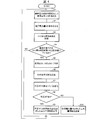
- FIG. 4 is a flowchart showing a process flow of the watt-hour meter 100.
- the first control device 108 obtains the power consumption B by time-integrating the sum of the instantaneous power value of the transmission line P1 and the instantaneous power value of the transmission line P3 (S1). After S1, the first controller 108 causes the display unit 104 to display the power consumption B obtained in S1 (S2).
- the first control device 108 acquires the current time from the RTC 106 (S3), compares the current time with the latest storage time of the power consumption A, and starts the second predetermined time (15 minutes) from the storage time. ) Is determined (S4).
- the first control device 108 repeats the processing after S1 when the second predetermined time has not elapsed since the latest storage time (NO in S4). On the other hand, when the second predetermined time has elapsed from the latest storage time (YES in S4), first control device 108 obtains power consumption A and stores it in first storage unit 107 (S5). After S5, the first controller 108 records the storage time of S5 in a memory (not shown) (S6). The storage time recorded in S6 is used when S4 is executed next.
- the first control device 108 transmits to the security sensor 109 an unauthorized log request command belonging to the power usage period corresponding to the used electric energy A obtained at S5 in the unauthorized act time (S7).
- the fraud log (the fraud log belonging to the power usage period corresponding to the power consumption A obtained in S5) is stored on the security sensor 109 side (YES in S8)
- the security sensor 109 transmits the fraud log to the first control device 108.
- the first control device 108 that has received the fraud log temporarily saves the fraud log in the first storage unit 107, and the power amount information indicating the fraud log and the power consumption A stored in S5. Is transmitted to the terminal device 600 of the electric power company (S9).
- the security log 109 does not store the fraud log (the fraud log belonging to the power usage period corresponding to the power consumption A obtained in S5) (NO in S8).
- the security sensor 109 transmits information indicating that the fraud log does not exist to the first control device 108.
- the first control device 108 that has received the information indicating that the unauthorized log does not exist indicates the power amount information indicating the used electric energy A stored in S5 without indicating the unauthorized log. It transmits to the terminal device 600 (S10).
- the first control device 108 repeats the processes after S1.
- the watt-hour meter 100 displays the power amount information indicating the used power amount A (used power amount for the second predetermined time) every second predetermined time (every 15 minutes) of the power company.
- the data is transmitted to the terminal device 600.
- the watt-hour meter 100 includes not only the used electric energy A but also an illegal log in the electric energy information.
- the power amount information is transmitted to the terminal device 600.
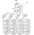
- FIG. 5 is a diagram illustrating a schematic configuration of an electric energy calculation system 800 of the present embodiment.
- the power amount calculation system 800 shown in FIG. 5 receives the power amount information indicating the used power amount A (measured value) from each watt hour meter in the distribution area of a certain power station of the power company, and uses the used power amount. It is a system which calculates
- an electric energy calculation system 800 connects a terminal device (center) 600, electric energy meters 100a to 100p, and the terminal device 600 and electric energy meters 100a to 100p so that they can communicate with each other. And a communication network 500.
- FIG. 5 shows only watt-hour meters 100a to 100p among the watt-hour meters installed in the distribution area, and omits the other watt-hour meters. .
- the communication network 500 may be a wireless communication network (for example, a wireless LAN) or a wired communication network (for example, a PLC (power line carrier)).
- a wireless communication network for example, a wireless LAN
- a wired communication network for example, a PLC (power line carrier)
- the energy meters 100a to 100d included in the energy calculation system 800 are grouped, and a repeater that relays between the terminal devices 600 is installed for each group. Specifically, as shown in FIG. 5, watt hour meters 100a to 100d are classified into group 1, watt hour meters 100e to 100h are classified into group 2, and watt hour meters 100i to 100l are classified into group 3. The watt hour meters 100m to 100p are classified into group 4.
- the communication network 500 includes a relay 150A that relays between each watt-hour meter in the group 1 and the terminal device 600, and a relay 150B that relays between each watt-hour meter in the group 2 and the terminal device 600.
- a relay 150C that relays between each watt-hour meter of group 3 and the terminal device 600
- a relay 150D that relays between each watt-hour meter of group 4 and the terminal device 600.
- all watt-hour meters transmit power amount information in a predetermined cycle (every second predetermined time (every 15 minutes)).
- the power amount information sent from the watt-hour meter of the group to which the device belongs is collected, and the collected power amount information is transmitted to the terminal device 600.
- the communication load in the power amount calculation system 800 is reduced.
- the terminal device 600 is a computer owned by an electric power company.
- the terminal device 600 receives the used electric energy A from each watt hour meter, and uses the used electric energy A of each watt hour meter to obtain the sum of the used electric energy in the distribution area.
- the sum of the power consumption A sent from each watt hour meter is simply calculated, the sum is calculated based on the power theft. Will be significantly less.
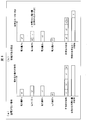
- FIG. 6A when there is no power theft in the watt-hour meters a to d, the total sum of the measured power consumption is equal to the total sum of the actual power consumption (FIG. 6). Are the measured values of the electric energy used by the electric energy meters a to d).
- FIG. 6 (b) when a power theft is performed by the watt-hour meter b, the total sum of the measured power consumption is greater than the sum of the actual power consumption.
- the amount of theft of electricity in the meter b is reduced (the amounts of power a2 to d2 are measured values of the amount of power used by the energy meters a to d, respectively).
- the terminal device 600 when there is a watt-hour meter that has been stolen, does not simply calculate the total amount of power consumption A, but a watt-hour meter that is not stealing (normal power amount) The total sum is obtained by correcting the used electric energy A of the watt-hour meter (illegal electric energy meter) for which theft is performed using the used electric energy A.
- the process of the terminal device 600 is demonstrated in detail.
- the terminal device 600 includes an arithmetic processing unit 601 and a third storage unit 602 as shown in FIG.
- the arithmetic processing unit 601 is a processor (for example, a CPU) that executes processing according to a program.
- the third storage unit 602 is a storage device in which information processed by the arithmetic processing unit 601 is stored. For example, a semiconductor memory or a hard disk is used.
- the arithmetic processing unit 601 receives power amount information from each watt hour meter at every second predetermined time (every 15 minutes), and uses the used power amount A indicated in the received power amount information to use power in the distribution area. Find the sum of quantities. However, in the present embodiment, the calculation processing unit 601 first obtains the sum (statistical value) of the power consumption A for each group, because the power amount information is transmitted collectively for each group. A value obtained by accumulating the sum total obtained every time is output as the sum total of the amount of power used in the distribution area.
- the third storage unit 602 stores a table AryA1 [M] in which data indicating the total amount of power consumption A is accumulated for each group.
- FIG. 8 is a diagram illustrating an example of the table AryA1 [M]. That is, in the third storage unit 602, a table AryA1 [M] as shown in FIG. 8 is stored for each group.
- the table AryA1 [M] in FIG. 8 is a last-in first-out stack. That is, at the time of reading data, the data is read in the order from when the writing time is closest to the current time. In FIG. 8, data having a larger number is data written earlier, and data having a smaller number is data written later. Data is read out in ascending order of numbers.
- FIG. 7 is a flowchart showing a flow of processing for obtaining the total amount of power consumption A in one group.
- the process for group 1 shown in FIG. 5 will be described as an example.
- the arithmetic processing unit 601 sets the initial value DefSumEN of the total sum of the power consumption A of group 1 and writes the initial value DefSumEN in the table AryA1 [M] of the third storage unit 602 ( S11). Specifically, it is as follows.
- the arithmetic processing unit 601 sets an initial value DefSumEN of the sum total of the power consumption A of the group 1 at a stage where the power amount information of the watt hour meters 100a to 100d of the group 1 has not yet been received.
- the initial value DefSumEN is the sum of the contracted capacities of the energy meters 100a to 100d belonging to the group 1. That is, the initial value DefSumEN is the sum of the contracted capacity of the watt-hour meter 100a, the contracted capacity of the watt-hour meter 100b, the contracted capacity of the watt-hour meter 100c, and the contracted capacity of the watt-hour meter 100d.
- the arithmetic processing unit 601 writes the initial value DefSumEN into the table AryA1 [M]. Since the initial value DefSumEN is a value that is obtained first, as shown in FIG. 8, the initial value DefSumEN is the oldest data (data written first) in the table AryA1 [M].
- the arithmetic processing unit 601 acquires the power amount information (information indicating the used power amount A) of each of the power meters 100a to 100d in the group 1 (S12).
- the arithmetic processing unit 601 determines whether there is a watt-hour meter (illegal watt-hour meter) in the group 1 that has been subjected to the power theft (S13). Specifically, the arithmetic processing unit 601 searches the power amount information indicating the unauthorized log in all the energy amount information acquired in S12, and the power amount information indicating the unauthorized log is one. If it is, however, it is determined that there is an unauthorized energy meter, and if there is no energy information indicating an unauthorized log, it is determined that there is no unauthorized energy meter.
- the arithmetic processing unit 601 obtains the sum SumEN of the used electric energy A of group 1 (S14).
- the sum SumEN is the power consumption A of the power meter 100a, the power consumption A of the power meter 100b, the power consumption A of the power meter 100c, and the power meter 100d used in the latest S12. It is the total with the electric energy A. That is, when there is no illegal power meter, the power consumption A acquired from each of the power meters 100a to 100d is added together.
- the arithmetic processing unit 601 writes the sum SumEN obtained in S14 to the table AryA1 [M] (S15).
- the watt-hour meter that has sent the watt-hour information for which the unauthorized log is not shown in S12 is a normal watt-hour meter
- the watt-hour meter that has sent the watt-hour information for which the unauthorized log is shown in S12 is illegal. It is a watt-hour meter.
- the arithmetic processing unit 601 obtains the number BadCnt of unauthorized power meters (S17).
- the number BadCnt of illegal watt-hour meters is a value obtained by subtracting the number of normal watt-hour meters GoodCnt from the number of watt-hour meters belonging to group 1.
- the arithmetic processing unit 601 obtains the total GoodEn of the used electric energy A of the normal watt-hour meter (S18). For example, if the watt hour meters 100a, 100c, and 100d are normal watt hour meters and the watt hour meter 100b is an illegal watt hour meter among the group 1 watt hour meters 100a to 100d, the total GoodEn is the watt hour meter 100a. This is the sum of the power consumption A, the power consumption A of the power meter 100c, and the power consumption A of the power meter 100d.
- the arithmetic processing unit 601 obtains a temporary sum SumTemp of the used electric energy A of the group 1 (S19). Specifically, the temporary sum (corrected sum) SumTemp is obtained by the following equation 1.
- (GoodEn / GoodCnt) in Equation 1 is an average value of the power consumption A of the normal watt hour meter of the group 1, and this average value is a value of the power consumption A of each of the illegal power meters of the group 1. It can be regarded as a correction value. This is because the average value of the actual power consumption of the illegal power meter of group 1 is measured from the normal power meter of group 1 rather than the average value of the power consumption A measured from the illegal power meter of group 1 The average value of the used electric energy A of the normal watt hour meters of the group 1 can be treated as the correction value of the used electric energy A of each illegal electric energy meter. Because it is possible.
- Equation 1 corresponds to the correction value for power consumption A of each unauthorized watt-hour meter
- [(GoodEn / GoodCnt) x BadCnt] in Equation 1 is the usage of unauthorized energy meter.
- This is a product of the correction value of the electric energy A and the number of illegal electric energy meters, and corresponds to the sum of the correction values of the used electric energy A of the illegal electric energy meter.
- the temporary sum SumTemp in Equation 1 is a value obtained by adding the sum of the used electric energy A of the normal watt hour meter and the sum of the correction values of the used electric energy A of the illegal watt hour meter. That is, the provisional sum SumTemp corresponds to the sum of the power consumption A of the group 1 power meters obtained by correcting the power consumption A of the illegal power meter using the power consumption A of the normal power meter. To do.
- the arithmetic processing unit 601 acquires the latest sum (SumPast) from AryA1 [M] (S20). That is, among the DefSumEN, SumEN, and SumTemp data listed in AryA1 [M] in FIG. 8, the data with the smallest associated number (No. 1 data) is extracted as SumPast.
- the arithmetic processing unit 601 determines whether or not the latest (previous) sum SumPast is equal to or greater than the provisional sum SumTemp (S21).
- the arithmetic processing unit 601 uses the latest sum SumPast as the current sum (sum of the power consumption A used by each watt-hour meter in group 1). Is written into the table AryA1 [M] (S22). In contrast, when the latest sum SumPast is not equal to or larger than the provisional sum SumTemp (NO in S21), the arithmetic processing unit 601 writes the provisional sum SumTemp to the table AryA1 [M] as the current sum (S23).
- the total amount of power consumption A of the watt-hour meter in group 1 is obtained by the third storage unit 602 through S15, S22, or S23. Will be written to the table AryA1 [M].
- the used electric energy A of each watt hour meter of group 1 is acquired again (S12), and the processes after S13 are performed. That is, a series of processes including the process of transmitting the used electric energy A from each watt-hour meter to the terminal device 600 and the process of calculating the sum of the used electric energy A by the arithmetic processing unit 601 are periodically performed. . As a result, the sum of the power consumption A of the watt-hour meter of group 1 is accumulated in the table AryA1 [M] every second predetermined time.
- the arithmetic processing unit 601 performs the above processing not only for the group 1 but also for other groups in the distribution area. Then, the arithmetic processing unit 601 outputs a value obtained by accumulating the sum obtained for each group as the sum of the power consumption in the distribution area. Then, the arithmetic processing unit 601 determines an appropriate distribution amount in the distribution area based on the total amount of power used in the distribution area thus output (the more appropriate distribution amount is determined as the total amount of power consumption increases). The smaller the total amount of power used, the smaller the appropriate power distribution).
- the power amount calculation system 800 includes a group (for example, group 1) composed of a plurality of watt-hour meters and the power consumption amount A measured in each watt-hour meter belonging to the group. And a terminal device 600 for obtaining the sum.
- Each watt-hour meter includes a watt-hour meter side unit 111 that measures the amount of power used, and sensors 201 to 203 that output sensor values used to detect fraud.
- the arithmetic processing unit 601 of the terminal device 600 causes the normal power
- the power consumption A of the unauthorized power meter is corrected using the power consumption A of the meter, and the sum of the power consumption A of each power meter belonging to the group is obtained.
- the unauthorized power meter exists in calculating the sum of the used power amounts measured by the watt-hour meters belonging to the group, the used power amount A of the normal watt-hour meter. Is used to correct the power consumption A of the unauthorized power meter, and the sum of the power consumption A of the power meters belonging to the group is obtained. Therefore, the calculated sum can be brought close to the actual value (the sum when there is no fraud) (can be suppressed from being significantly smaller than the actual value). Therefore, if the total sum is obtained for each group as described above and the appropriate power generation amount is determined from the sum for each group, the appropriate power generation amount approaches the actual value. This makes it possible to reduce the energy loss of power generation by an electric power company.
- the provisional sum obtained by Equation 1 is a value that is different from the actual sum.
- the temporary sum is a value that is far from the actual sum
- a value (SumPast) closer to the actual sum than the provisional sum can be adopted by S21 to S23. Have.
- the provisional sum obtained by Equation 1 has a smaller error (difference from the actual value) as the number of samples (the number of watt-hour meters in the group) increases, so the communication load on the communication network 500 becomes excessive. It is preferable that the number of watt-hour meters in the group is as large as possible.
- a plurality of groups are set in the distribution area of a certain power plant, and the processing of FIG. 7 is performed for each group to obtain the total amount of power used.
- the entire distribution area of a certain power plant may be regarded as one group, and the process shown in FIG. 7 may be performed on the group to obtain the total amount of power used by the group. In this case, the total amount of power used for one group becomes the total amount of power used in the distribution area of a certain power plant.
- the watt-hour meter 100 performs threshold processing on the output values of the sensors 201 to 203 to detect fraud, and generates a log when fraud is detected.
- fraud detection may not be performed on the watt-hour meter 100 side, and the presence or absence of a fraudulent act of each watt-hour meter 100 may be detected on the terminal device 600 side.
- the watt-hour meter 100 periodically transmits power amount information indicating the amount of power used and the output values of the sensors 201 to 203 to the terminal device 600.
- the terminal device 600 refers to the output value.
- the radio wave sensor 201, the electrostatic sensor 202, and the magnetic sensor 203 are used.
- the sensor is of course limited to these sensors as long as it is a sensor that can detect an illegal act leading to theft. Is not to be done.
- an acceleration sensor that detects an impact applied to the watt hour meter 100 or a temperature sensor that detects that the watt hour meter 100 has been lit may be used. This is because imparting (breaking) impact and arson to the watt-hour meter 100 are also actions related to the theft of electricity.
- the number of sensors is not limited.
- the security sensor 109 of the watt-hour meter 100 may of course be equipped with five of the radio wave sensor 201, the electrostatic sensor 202, the magnetic sensor 203, the acceleration sensor, and the temperature sensor.
- a single sensor is used such that radio wave emission is detected from the output value (sensor value) of the radio wave sensor 201 and magnetic emission is detected from the output value of the magnetic sensor 203.
- the presence or absence of a single fraudulent act is determined from the output of, but the fraudulent act may be determined by combining the output values of a plurality of sensors. For example, from the combination of the output of the radio wave sensor 201 and the output of the electrostatic sensor 202, it is possible to determine whether radio wave emission, electrostatic discharge, or interference wave emission has been performed.
- the watt-hour meter 100 of the present embodiment can periodically transmit to the terminal device 600 an unauthorized log (or output value of each sensor) indicating the presence or absence of an unauthorized act that leads to theft of electricity and the used electric energy.
- 1 is not limited to the structure of FIG. 1, and the types of detectable frauds are not limited, and are limited to fraud log generation methods and fraud determination methods. It is not a thing.
- S21 of FIG. 7 it is determined whether or not the most recent sum SumPast is greater than or equal to the provisional sum SumTemp, but it is determined whether or not the most recent sum SumPast is greater than the provisional sum SumTemp. (SumTemp ⁇ SumPast may be determined).
- S22 is executed if SumPast is larger than SumTemp, and S23 only needs to be executed if SumTemp is larger than SumPast.
- the power amount calculation system includes a terminal device that obtains a group of a plurality of watt-hour meters and a statistical value of power consumption measured in each watt-hour meter belonging to the group.
- the watt-hour meter includes a watt-hour meter that measures the amount of power used, and a sensor that outputs a sensor value used for detecting fraud.
- the terminal device uses the amount of power used by the normal watt-hour meter.
- an arithmetic processing unit for correcting the power consumption of the unauthorized power meter to obtain the statistical value.
- the said normal watt-hour meter is obtained by correcting the power consumption amount of the unauthorized power meter using the power consumption amount. Therefore, the calculated statistical value can be brought close to the actual value (the statistical value when there is no fraud) (can be suppressed from being significantly smaller than the actual value). Therefore, if the appropriate power generation amount is determined using the statistical value, the appropriate power generation amount approaches the actual value, so that it is possible to suppress the excess power generation amount for suppressing power outages compared to the conventional power generation. There is an effect that energy loss of the company's power generation can be reduced.
- the average value of the actual power consumption of the illegal power meter is closer to the average value of the power consumption measured from the normal power meter than the average value of the power consumption measured from the illegal power meter. Since there is a tendency, the average value of the electric energy used by the normal electric energy meter can be regarded as a correction value for the electric energy used by each unauthorized electric energy meter.
- the arithmetic processing unit when the sum of used electric energy of electric energy meters belonging to the group is set as the statistical value, the arithmetic processing unit is configured to output the unauthorized power.
- the arithmetic processing unit When there is a meter, it is obtained by adding the product of the average value of the amount of power used by the normal power meter and the number of illegal power meters and the sum of the amount of power used by the normal power meter The corrected sum is used as the value, and the corrected sum is used as the statistical value.
- the average value of the power consumption of the normal watt hour meter corresponds to the correction value of the power consumption of each illegal power meter
- the multiplication value is the sum of the correction values of the power consumption of the illegal power meter.
- the correction sum is a value obtained by adding the sum of the power consumption of the normal power meter and the sum of the correction values of the power consumption of the illegal power meter. Therefore, according to the above configuration, the statistical value is obtained by correcting the power consumption of the unauthorized power meter using the power consumption of the normal power meter.
- the required correction sum may be a value that is far from the actual sum.
- the power amount calculation system includes a step of transmitting the used power amount from the watt hour meter to the terminal device, and the calculation processing unit of the terminal device includes the calculation processing unit.
- a series of processes including the step of obtaining the statistical value using the used electric energy is periodically performed, and the arithmetic processing unit is configured to correct the correction when there is the illegal electric energy meter when obtaining the current statistical value. If the corrected total is greater than the previous statistical value, the corrected total is the current statistical value. If the corrected total is smaller than the previous statistical value, the current statistical value is the same as the previous statistical value. It is characterized by doing.
- the present invention can be used in an electric energy calculation system that receives and aggregates the amount of electric power used from each watt-hour meter (so-called smart meter) that is widely used in the distribution areas of electric power companies.
Landscapes
- Physics & Mathematics (AREA)
- General Physics & Mathematics (AREA)
- Engineering & Computer Science (AREA)
- Power Engineering (AREA)
- Remote Monitoring And Control Of Power-Distribution Networks (AREA)
- Management, Administration, Business Operations System, And Electronic Commerce (AREA)
Abstract
電力量計(100a~100d)からなるグループ1のうち、不正行為が行われてない電力量計を正常電力量計とし、不正行為が行われている電力量計を不正電力量計とすると、演算処理部(601)は、正常電力量計の使用電力量を用いて不正行為が行われた不正電力量計の使用電力量を補正してグループ1の使用電力量の総和を求める。
Description
本発明は、電力会社によって電力が供給される配電地域に設置されている各電力量計を利用して前記配電地域における使用電力量の統計値(例えば総和)を演算する電力量演算システムに関する。
特許文献1に示されるように、電力量計に不正行為を施すことによって盗電(電力を盗む)を行う不正者が従来から存在する。
特に、スマートメータ(デジタル方式の電力量計)について、破壊・改造行為を伴う盗電(例えば扉を壊して不正なバイパス配線の形成を行う等)ではなく、破壊・改造行為を伴わない盗電が問題視されている。破壊・改造行為を伴わない盗電は、外観上盗電の形跡が残らないため、常時行うのではなく一時的または間欠的に行うようにすれば、露見しないことが多いためである。以下、破壊・改造行為を伴わない盗電の一例を説明する。
スマートメータは、デジタル方式で使用電力量を計測して出力(表示または送信)する装置であり、少なくとも、電流センサ、表示部、プロセッサを備えている。スマートメータでは、プロセッサが、供給対象へ供給される電力量(使用電力量)を電流センサの出力に基づいて計測し、表示部を制御することによって当該使用電力量を表示(出力)するようになっている。
ここで、スマートメータの近傍にて強力な磁気を発生させると、当該磁気が発生している間、磁気の影響で電流センサの機能が低下し、電流センサが電流量を出力しなくなり、プロセッサが使用電力量を計測できなくなることがある(但し、磁気の発生を止めると、電流センサは正常状態に戻って電流量を出力するようになり、プロセッサが使用電力量を計測可能になる)。
それゆえ、不正者は、スマートメータの近傍において磁気発生器にて一時的に磁気を発生させることで一時的に電力量計測を停止させるという盗電を行うことがある。このような磁気発生行為による盗電は、破壊・改造行為を伴わないため、常時行うのではなく一時的または間欠的に行うようにすれば、露見しないことが多い。
これに対し、破壊・改造行為を伴わない不正行為を検出するためのセンサを電力量計(スマートメータ)に取り付ければ、不正行為が行われたエビデンスを収集できる。例えば、磁気を検出する磁気センサを電力量計に取り付け、磁気センサのセンサ値に対して閾値処理を行えば磁気による不正行為の有無を判定でき、判定結果のログは前記のエビデンスとなり得る。
ところで、電力量計を管理する電力会社は、発電所の発電量を適正(発電量≒使用電力量)に調整するために、配電地域の各電力量計から収集した使用電力量の合計(総和)から適正発電量を定めている。
ここで、盗電行為が頻繁に行われるような国では、前記の使用電力量の合計は盗電行為によって実際値よりも大幅に少ない値になる。それゆえ、盗電行為を考慮せずに前記の使用電力量の合計に基づいて定めた適正発電量の発電を行うだけでは、配電地域において供給電力量不足が生じて停電が生じることがある。
そこで、このような国の電力会社では、前記適正発電量(前記の使用電力量の合計に基づいて定められる発電量)よりも余分に発電を行うことによって停電を抑制している。しかし、余分に発電させる量(余分発電量)をどの程度に設定するべきか不明であることから、停電を抑制するためには余分発電量を過剰に設定しなければならず、エネルギーロスが生じるという問題がある。
本発明は、以上の問題に鑑みてなされたものであり、電力会社の発電におけるエネルギーロスを低減することの可能な電力量演算システムを提供することを目的とする。
前記目的を達成するために、本発明は、複数の電力量計からなるグループと、前記グループに属する各電力量計において計測される使用電力量の統計値を求める端末装置とを含む電力量演算システムであって、前記電力量計は、前記使用電力量を計測する電力量計側部と、不正行為の検出に用いられるセンサ値を出力するセンサとを備え、前記不正行為が検出された電力量計を不正電力量計とし、前記不正行為が検出されなかった電力量計を正常電力量計とすると、前記端末装置は、前記正常電力量計の使用電力量を用いて前記不正電力量計の使用電力量を補正して前記統計値を求める演算処理部を備えたことを特徴とする。
本発明は、停電を抑制するための余分発電量を従来よりも抑えることが可能になり、電力会社の発電のエネルギーロスを低減できるという効果を奏する。
〔盗電行為の態様〕
本実施形態の電力量計、および、当該電力量計を備えた電力量演算システムを説明する前に、前提事項となる盗電行為の態様について説明する。
本実施形態の電力量計、および、当該電力量計を備えた電力量演算システムを説明する前に、前提事項となる盗電行為の態様について説明する。
本実施形態の電力量計は、所謂スマートメータであり、主な盗電態様としては、(1)磁気放出によって電力量計の電流センサの機能を低下させる盗電と、(2)電波放出または静電気放電(ESD)によってプロセッサをハングアップさせる盗電とがある。
磁気放出による盗電は、背景技術にて説明した通りである。すなわち、電力量計では、プロセッサが電流センサのセンサ値を用いて使用電力量を計測するようになっているが、不正者は、電力量計の近傍にて強力な磁気を発生させることにより、電流センサの機能を低下させて電流量を出力できなくすることで、使用電力量の計測をできなくして盗電を行う(ただし、磁気の発生を止めると、電流センサは正常状態に戻って電流量を出力するようになり、プロセッサが使用電力量を計測可能になる)。
電波放出または静電気放電による盗電は、以下の通りである。電力量計のプロセッサは、電流センサに基づいて使用電力量を計測する他、表示部を制御することによって当該使用電力量を表示(出力)するようになっている。それゆえ、当該プロセッサは、表示部との間で信号の送受信を行うようになっている。ここで、電力量計において、表示部は、外部から視認可能にする必要があるため、電磁シールドで保護されていない。それゆえ、電力量計のプロセッサ自体は、電磁シールドで保護されているものの、表面積が広く且つ電磁シールドで保護されていない表示部との間で信号の送受信を行う関係上、電波放出または静電気放電(ESD)に対する耐性が低い。そこで、不正者は、一時的に電波放出または静電気放電を起こして電力量計のプロセッサを一時的にハングアップさせる。つまり、スマートメータのプロセッサがハングアップされている間、電力供給が行われても使用電力量が計測されないため、盗電が可能になるのである(電波放出または静電気放電の発生を止めると、プロセッサは正常状態に戻って使用電力量を計測可能になる)。
盗電行為の態様としては以上のようなものが挙げられるが、以上の盗電行為を常時行い続けると盗電行為が露見してしまう。この理由は以下の通りである。電力量計は、通信網を介して電力会社の端末装置と接続されており、周期的に(例えば15分間ごとに)、使用電力量を示すデータを端末装置に送信するようになっている。
それゆえ、少なくとも送信周期の長さを超える長期間において連続して磁気を発生させて盗電を行うと、送信されるデータに示される使用電力量が常にゼロになってしまい、すぐに盗電が露見してしまう。
また、少なくとも送信周期の長さを超える長期間において電波放出(または静電気放電)によってプロセッサをハングアップさせ続けると、そもそも通信処理を制御するプロセッサ自体が通信処理を制御できなくなるため、使用電力量を示すデータの送信タイミングになっても当該データが電力会社の端末装置へ送信されず、すぐに盗電が露見してしまう。
そこで、通常、不正者は、電力量計を常に異常状態(電流センサの機能低下、または、プロセッサのハングアップ)にするのではなく、図9に示すように、使用電力量を示すデータの送信タイミングと次の送信タイミングとの間の期間うち、両送信タイミングから間隔をもった一部期間のみ異常状態にし、他の期間では電力量計を正常に作動させるようになっている。具体的には、不正者は以下のようにして盗電を行う。
不正者は、盗電に使用する磁気発生装置、電波発生装置、または、静電気放電装置を、盗電対象となる電力量計の近傍に設置する。
磁気発生装置は、アンテナと、プロセッサと、プロセッサに制御されることにより磁気を発生する磁気発生部(例えば電磁石)とを備える。アンテナは、電力量計が通信網を介した送信処理を行う場合に当該送信処理によって発生する電波を検出する(通信網が無線通信網の場合は無線通信により発生する電波を検出するが、通信網が有線(例えばPLC)の場合は当該有線からの漏洩電波を検出する)。プロセッサは、当該アンテナの検出結果を参照して周期的に行われている送信処理(電力量を示すデータの送信)の送信周期を判断する。そして、プロセッサは、当該送信周期に基づき、使用電力量を示すデータの送信タイミングと次の送信タイミングとの間の期間うち、両送信タイミングから間隔をもった一部期間のみ磁気発生部に磁気を発生させ、他の期間では磁気発生部に磁気の発生を停止させる。これにより、図9に示す異常状態の期間は磁気によって電流センサの機能が低下して電力量の計測を不能にする一方、正常状態の期間は磁気を発生させないため電力量が計測されることになる。それゆえ、送信処理にて送信されるデータの使用電力量はゼロになり難く、盗電が露見され難い。
電波発生装置は、アンテナと、プロセッサと、プロセッサに制御されることにより電波を発生する電波発生部とを備える。電波発生装置のアンテナは、磁気発生装置のアンテナと同じ機能を有するものである。電波発生装置のプロセッサは、磁気発生装置のプロセッサと同様に送信周期を判断する。そして、電波発生装置のプロセッサは、当該送信周期に基づき、使用電力量を示すデータの送信タイミングと次の送信タイミングとの間の期間うち、両送信タイミングから間隔をもった一部期間のみ電波発生部に電波を発生させ、他の期間では電波発生部に電波の発生を停止させる。これにより、図9に示す異常状態の期間は電波によって電力量計のプロセッサをハングアップさせて電力量の計測を不能にする一方、正常状態の期間は電波を発生させないため電力量が計測されることになる。また、送信タイミングは正常状態の期間に含まれる。それゆえ、送信処理にて送信されるデータの使用電力量はゼロになり難く、且つ、周期的な送信処理も正常に行われるため、盗電が露見され難い。
静電気放電装置は、アンテナと、プロセッサと、プロセッサに制御されることにより静電気を放電する静電気放電部とを備える。静電気放電装置のアンテナは、磁気発生装置のアンテナと同じ機能を有するものである。静電気放電装置のプロセッサは、磁気発生装置のプロセッサと同様に送信周期を判断する。そして、静電気放電装置のプロセッサは、当該送信周期に基づき、使用電力量を示すデータの送信タイミングと次の送信タイミングとの間の期間うち、両送信タイミングから間隔をもった一部期間のみ静電気放電部に静電気を発生させ、他の期間では静電気放電部に静電気の放電を停止させる。これにより、図9に示す異常状態の期間は静電気放電によって電力量計のプロセッサをハングアップさせて電力量の計測を不能にする一方、正常状態の期間は静電気放電を中止するため電力量が計測されることになる。また、送信タイミングは正常状態の期間に含まれる。それゆえ、送信処理にて送信されるデータの使用電力量はゼロになり難く、且つ、周期的な送信処理も正常に行われるため、盗電が露見され難い。
不正者は、以上のような磁気発生装置、電波発生装置、または、静電気放電装置を使用することにより、実際の使用量よりも少ない使用電力量(但しゼロでない)が示されるデータを電力量計から電力会社へ周期的に送信させることができ、盗電を行いつつも、盗電の露見を抑制しているのである。
これに対し、本発明の一実施形態の電力量計では、以上のような磁気発生装置、電波発生装置、または、静電気放電装置を使用する不正行為(盗電のための不正行為)を検出し、盗電のための不正行為が行われた事を示す不正ログを電力会社の端末装置へ送信する機能を備えている。以下、本実施形態の電力量計を説明する。
〔電力量計の全体構成〕
電力量計100は、図1に示すように、三相交流方式の送電線P1~P3を介して計測対象(例えば家屋等)へ供給される電力の電力量をデジタル方式によって計測するスマートメータである。
電力量計100は、図1に示すように、三相交流方式の送電線P1~P3を介して計測対象(例えば家屋等)へ供給される電力の電力量をデジタル方式によって計測するスマートメータである。
電力量計100は、同図に示されるように、電流センサCT1・CT3と、分圧回路102と、電源回路103と、表示部104と、外部通信部105と、RTC106と、第1記憶部107と、第1制御装置108と、セキュリティセンサ109とを備えている。
電流センサCT1は、送電線P1の電流値IP1を検出するセンサであり、電流センサCT3は、送電線P3の電流値IP3を検出するセンサである。分圧回路102は、送電線P1の電圧値VP1と、送電線のP3の電圧値VP3とを検出するセンサである。電源回路103は、電力量計100が備える各ハードウェアに対して電力を供給する電源である。
表示部104は、第1制御装置108と電気的に直接接続されており、第1制御装置108に制御されることによって使用電力量を表示出力する表示装置である。表示部104としては例えば液晶表示装置が用いられる。なお、表示部104は、電力量計100の外部から視認可能なように電力量計100に取り付けられている。これは、表示部104に表示される内容を電力使用者に視認させるためである。
外部通信部105は、図5に示される通信網500を介して電力会社の端末装置600との間で通信を行うための通信ポートである。なお、通信網500は、無線通信網(例えば無線LAN)であってもよいし、有線通信網(例えばPLC(電力線搬送))であってもよい。
第1記憶部107は、情報の保存を行う記憶領域であり、本実施形態ではEEPROM(登録商標;Electrically Erasable Programmable Read-Only Memory)が用いられる。なお、第1記憶部107に対する情報の読み書きは、第1制御装置108によって実行される。
第1制御装置108は、電力量計100の各ハードウェアを制御する制御回路基板であり、具体的にはプログラムによって処理を実行するプロセッサ(例えばCPU(Central Processing Unit))が用いられる。
第1制御装置108は、図1に示すように、電力量計側部111、表示制御部112、不正ログ取得部113、および外部通信制御部114を備えている。なお、第1制御装置108はハードウェアであるが、第1制御装置108に含まれる各ブロック111~114は、第1制御装置108が実行するソフトウェアの機能を示す機能ブロックである。
電力量計側部111は、電流センサCT1、CT3、および分圧回路102の検出値を用いて、送電線P1~P3を介して電力供給対象へ供給される電力の電力量(電力供給対象の使用電力量)を演算(計測)する処理を行うブロックである。
具体的には、電力量計側部111は、電流値IP1と電圧値VP1とを乗じて送電線P1の瞬時電力値を求め、電流値IP3と電圧値VP3とを乗じて送電線P3の瞬時電力値を求め、送電線P1の瞬時電力値と送電線P3の瞬時電力値との和を時間積分することによって、第1所定時間(例えば数秒)の使用電力量(使用電力量Bと称す)を求めている。
また、電力量計側部111は、第1所定時間よりも長い第2所定時間(本実施形態では15分)が経つ度に、第2所定時間の使用電力量(使用電力量Aと称す)を求め、当該使用電力量Aを第1記憶部107に保存する。具体的には、使用電力量Aを示すデータの前回の保存時から第2所定時間が経つと、電力量計側部111は、現時点と現時点から第2所定時間遡った時点との間に求められた使用電力量Bの積算値を使用電力量Aとして求め、求めた使用電力量Aを第1記憶部107に保存する。
また、電力量計側部111は、日毎の使用電力量や月毎の使用電力量を求めて第1記憶部107に保存するようになっていてもよい。
表示制御部112は、表示部104を制御するブロックである。表示制御部112は、電力量計側部111が使用電力量Bを求める度に当該使用電力量Bを電力量計側部111から取得し、当該使用電力量Bを表示部104に表示させる。
なお、表示制御部112は、外部から入力されるコマンド(オペレータのコマンド)に応じて、第1記憶部107に保存されている、使用電力量A(15分間の使用電力量)、日毎の電力量、月毎の電力量のいずれかを表示部104に表示させるようになっていてもよい。
不正ログ取得部113は、セキュリティセンサ109が生成する不正ログ(後に詳述する)をセキュリティセンサ109から取得し、この不正ログを第1記憶部107に保存する処理を行う。具体的には、不正ログ取得部113は、電力量計側部111によって使用電力量Aの演算処理が行われると、不正行為時刻が使用電力量Aに対応する電力使用期間内(本実施形態では使用電力量Aの算出時刻と当該算出時刻から第2所定時間遡った時点との間)になっている不正ログの要求コマンドをセキュリティセンサ109に送信する。ここで、セキュリティセンサ109は、不正行為時刻が前記電力使用期間内(所定計測期間内)になっている不正ログがあれば当該不正ログを不正ログ取得部113に送信し、不正ログ取得部113は、セキュリティセンサ109から送られてくる不正ログを第1記憶部107に保存する。
外部通信制御部(通信処理部)114は、電力量計側部111に使用電力量Aが求められる度に、外部通信部105を制御して、使用電力量Aを示す電力量情報を、電力会社の端末装置600(図5参照)へ送信する処理を行う。
また、外部通信制御部114は、不正行為時刻が送信対象となる使用電力量Aに対応する電力使用期間内になっている不正ログが不正ログ取得部113に取得されて第1記憶部107に保存されている場合、使用電力量Aと当該不正ログとを示す電力量情報を、電力会社の端末装置600に送信するようになっている。
RTC106は、年月日および時分秒を含めた現在時刻を示す時刻情報を出力するリアルタイムクロックである。なお、RTC106は、バックアップ電池(不図示)が接続されているため、停電等によって停止せず、常に正確な時刻情報を出力する。第1制御装置108は、RTC106の時刻情報に基づいて現在時刻を認識するようになっている。また、後述するセキュリティセンサ109の第2制御装置207(図2参照)は、セキュリティセンサ109の起動時に、RTC106の時刻情報を第1制御装置108から取得し、取得した現在時刻を不図示のタイマに設定し、このタイマに基づいて現在時刻を認識するようになっている。
つぎに、セキュリティセンサ109について説明する。図2は、図1に示されるセキュリティセンサ109が備える各ハードウェアを示すブロック図である。図3は、セキュリティセンサ109の外観図である。図3の(a)は、セキュリティセンサ109の正面を示す斜視図である。図3の(b)は、セキュリティセンサ109の裏面を示す斜視図である。図3の(c)は、セキュリティセンサ109の上面図である。図3の(d)は、セキュリティセンサ109の正面図である。図3の(e)は、セキュリティセンサ109の側面図である。図3の(f)は、セキュリティセンサ109の裏面図である。図3の(g)は、セキュリティセンサ109の下面図である。
セキュリティセンサ109は、電力量計100に対する不正行為(盗電のための不正行為)を検出するための検出装置であり、電力量計100の内部に取り付けられる。なお、セキュリティセンサ109は、電力量計100に対して着脱可能である。
セキュリティセンサ109は、図2に示すように、電波センサ201、静電気センサ(センサ)202、磁気センサ203、第2記憶部206、および、第2制御装置207を備えている。なお、セキュリティセンサ109は、図3(a)に示す樹脂製のパッケージ(筐体)109aを有し、パッケージ109aが図2に示される各部材201~203、206、および207を収容している。
電波センサ(センサ)201は、電子機器に対する電波障害(EMI)の要因となる周波数帯域の電波の量に相関するセンサ値AD1を出力するセンサである。具体的には、使用電力量を計測するプロセッサ(本実施形態では第1制御装置108)をハングアップさせるための電波放出が行われると、電波センサ201から出力されるセンサ値AD1が高くなる。なお、電波放出によって第1制御装置108がハングアップすると、第1制御装置108は使用電力量を計測できず、盗電が生じることになる。
静電気センサ(ESD Surge sensor)202は、電力量計100において電荷のサージ現象が生じた場合の電荷の増加量に相当するセンサ値AD2を出力するセンサである。具体的には、電力量を計測するプロセッサ(本実施形態では第1制御装置108)をハングアップさせるための静電気放電が行われると、電力量計100にて電荷のサージ現象が生じ、センサ値AD2が高くなる。なお、静電気放電によって第1制御装置108がハングアップすると、第1制御装置108は電力量を計測できず、盗電が生じることになる。
磁気センサ(センサ)203は、磁場の大きさに相関するセンサ値AD3を出力するセンサである。具体的には、電流センサCT1・CT3の機能低下を目的として電力量計100に磁気が放たれると、磁気センサ203から出力されるセンサ値AD3は高くなる。なお、電流センサCT1・CT3が機能低下すると、電流量が正常に出力されないため、電力量計側部111は電力量を計測できず、盗電が生じることになる。
第2記憶部206は、情報の保存を行う記憶領域であり、本実施形態ではフラッシュメモリが用いられる。第2記憶部206に対する情報の読み書きは、第2制御装置207によって実行される。
第2制御装置207は、第1制御装置108とは別体の制御回路基板であり、セキュリティセンサ109の各ハードウェアを制御するプロセッサ(例えばCPU)である。第2制御装置207は、各センサ201~203のセンサ値を受信し、当該センサ値に対して閾値処理を行うことにより、盗電のための不正行為が生じた事が示されている不正ログを生成して第2記憶部206に保存する。また、第2制御装置207は、不正行為時刻が使用電力量Aに対応する電力使用期間内に属している不正ログの要求コマンドを第1制御装置108から受け取ると、当該不正ログがあれば当該不正ログを送信する。
〔電波放出または静電気放電に対する耐性について〕
つぎに、第1制御装置108および第2制御装置207の電波放出または静電気放電に対する耐性について説明する。
つぎに、第1制御装置108および第2制御装置207の電波放出または静電気放電に対する耐性について説明する。
一般的に、電力量計においては、外部からオペレータが表示部を視認可能になるように設計しなければならない関係上、表示部は電磁シールドに保護されていない。そして、表示部は、表面積が広いハードウェアであるため、電力量計に対して電波放出または静電気放電が行われた場合、当該表示部と信号の送受信を行う制御回路(プロセッサ)には、表示部または外部通信部との間の配線を介して電波または静電気が容易に伝わってしまう。それゆえ、表示部と信号の送受信を行う制御回路は、ハングアップが生じやすく、電波または静電気に対する耐性が低い。
すなわち、本実施形態においても、電力量計100の表示部104と信号の送受信を行う第1制御装置108は、電波放出または静電気放電に対する耐性が低く、電力量計100に対して電波放出または静電気放電が行われると、ハングアップが生じやすい。
これに対し、本実施形態の第2制御装置207は、表示部104との間で信号の送受信を行わず、第1制御装置108、第2記憶部206、各センサ201~203との間で信号の送受信を行うように設計されている。それゆえ、第2制御装置207は、電波放出または静電気放電に対する耐性が高く(少なくとも第1制御装置108よりは高い)、電力量計100に対して電波放出または静電気放電が行われても、ハングアップが生じ難い。その理由は以下の通りである。
一般的に、制御装置や記憶装置等の回路基板同士を繋ぐ配線は、電波および静電気の伝達が抑制されるように設計されており、電磁シールドによる保護の無い表示部と回路基板とを繋ぐ配線よりも、電波および静電気の伝達が抑えられるのである。それゆえ、電力量計100に対して電波放出や静電気放電が行われても、表示部104から第1制御装置108までは電波または静電気が容易に伝わってしまうが、第1制御装置108から第2制御装置207へは電波または静電気は伝わり難い。また、第2制御装置207は、センサ201~203と信号の送受信を行うようになっているが、センサ201~203は、表示部104と比べ、極めてサイズが小さく、表面積も極めて小さい。それゆえ、電力量計100に対して電波放出や静電気放電が行われても、表面積の大きい表示部104から第1制御装置108へは電波または静電気が容易に伝わってしまうが、表面積の小さい各センサ201~203から第2制御装置207へは電波または静電気は伝わり難い。それゆえ、第2制御装置207は、電波放出または静電気放電に対する耐性が高く(少なくとも第1制御装置108よりは高い)、電力量計100に対して電波放出または静電気放電が行われても、ハングアップが生じ難いのである。
つまり、電力量計100に対して電波放出または静電気放電が行われて第1制御装置108がハングアップしている期間が生じても、第2制御装置207は正常動作を続けることができる。この期間において、第1制御装置108は電力量を計測できないため、盗電が生じることになるが、第2制御装置207は、正常に動作して不正ログを記録できるようになっている。
〔第2制御装置207について〕
つぎに、第2制御装置207の詳細について説明する。図2に示すように、第2制御装置207は、少なくとも不正ログ生成部301および通信制御部302を備えている。なお、第2制御装置207はハードウェア(CPU)であるが、第2制御装置207に含まれる各ブロック301、302は、第2制御装置207が実行するソフトウェアの機能を示す機能ブロックである。
つぎに、第2制御装置207の詳細について説明する。図2に示すように、第2制御装置207は、少なくとも不正ログ生成部301および通信制御部302を備えている。なお、第2制御装置207はハードウェア(CPU)であるが、第2制御装置207に含まれる各ブロック301、302は、第2制御装置207が実行するソフトウェアの機能を示す機能ブロックである。
不正ログ生成部301は、センサ201~203の各々から出力される各センサ値を監視し、各センサ値が閾値未満から閾値以上に変化した場合に不正行為がなされた事を検出し、不正行為を示す不正ログを生成するブロックである。不正ログ生成部301による処理を詳細に説明すると、以下の通りである。
本実施形態では、センサ201~203毎に、各々のセンサにて専ら使用される閾値が予め設定されている。不正ログ生成部301は、センサ201~203毎に、出力されるセンサ値と閾値とを対比し続ける。不正ログ生成部301は、センサ値が閾値未満から閾値以上に変化した事をもって不正行為を検出し、不正行為を示した不正ログを生成して第2記憶部206に保存するようになっている。不正ログには、センサ値が閾値未満から閾値以上に変化した事が検出された時刻(不正行為時刻)と、当該センサ値を出力するセンサに応じた不正行為の種類とを示した情報とが示される。
具体的には、不正ログ生成部301は、電波センサ201のセンサ値AD1が閾値未満から閾値以上に変化すると、不正行為時刻が示され、且つ、不正行為として電波放出が示される不正ログを生成する。また、不正ログ生成部301は、静電気センサ202のセンサ値AD2が閾値未満から閾値以上に変化すると、不正行為時刻が示され、且つ、不正行為として静電気放電が示される不正ログを生成する。また、不正ログ生成部301は、磁気センサ203のセンサ値AD3が閾値未満から閾値以上に変化すると、不正行為時刻が示され、且つ不正行為として磁気放出が示される不正ログを生成する。
つぎに、図2に示す通信制御部302を説明する。通信制御部302は、第1制御装置108との間で通信を行うブロックである。具体的には、通信制御部302は、電力量計側部111にて求められた使用電力量Aに対応する電力使用期間内に不正行為時刻が属している不正ログの要求コマンドを不正ログ取得部113から取得すると、不正行為時刻が前記電力使用期間に属している不正ログが第2記憶部206に保存されていれば当該不正ログを不正ログ取得部113に送信するようになっている。
つまり、不正ログ取得部113は、使用電力量Aの電力使用期間(使用電力量Aの算出時刻と当該算出時刻から第2所定時間遡った時点との間)を示した要求コマンドを通信制御部302に送信する。この要求コマンドを受信した通信制御部302は、第2記憶部206において、前記要求コマンドに示されている電力使用期間内に不正行為時刻が含まれている不正ログを検索する。通信制御部302は、当該不正ログが第2記憶部206にあれば、当該不正ログを不正ログ取得部113(第1制御装置108)へ送信し、当該不正ログが第2記憶部206に無ければ、当該不正ログが存在しない事を示す情報を不正ログ取得部113(第1制御装置108)へ送信する。
〔電力量計100の処理フロー〕
つぎに、電力量計100にて行われる処理の流れをフローチャートに基づいて説明する。図4は、電力量計100の処理の流れを示すフローチャートである。
つぎに、電力量計100にて行われる処理の流れをフローチャートに基づいて説明する。図4は、電力量計100の処理の流れを示すフローチャートである。
図4に示すように、まず、第1制御装置108は、送電線P1の瞬時電力値と送電線P3の瞬時電力値との和を時間積分することによって使用電力量Bを求める(S1)。S1の後、第1制御装置108は、S1で求められた使用電力量Bを表示部104に表示させる(S2)。
S2の後、第1制御装置108は、RTC106から現在時刻を取得し(S3)、現在時刻と使用電力量Aの直近の保存時刻とを対比し、当該保存時刻から第2所定時間(15分間)が経っているか否かを判定する(S4)。
第1制御装置108は、直近の保存時刻から第2所定時間経過していない場合(S4にてNO)、S1以降の処理を繰り返す。これに対し、第1制御装置108は、直近の保存時刻から第2所定時間経っている場合(S4にてYES)、使用電力量Aを求めて第1記憶部107に保存する(S5)。S5の後、第1制御装置108は、S5の保存時刻をメモリ(不図示)に記録する(S6)。S6にて記録される保存時刻は、次にS4が実行される際に使用されるものである。
つぎに、第1制御装置108は、不正行為時刻がS5にて求めた使用電力量Aに対応する電力使用期間内に属する不正ログの要求コマンドをセキュリティセンサ109に送信する(S7)。
ここで、セキュリティセンサ109側に当該不正ログ(不正行為時刻がS5にて求めた使用電力量Aに対応する電力使用期間内に属する不正ログ)が保存されている場合(S8にてYES)、セキュリティセンサ109は、当該不正ログを第1制御装置108へ送信する。そして、当該不正ログを受信した第1制御装置108は、当該不正ログを一旦第1記憶部107に保存し、当該不正ログとS5にて保存された使用電力量Aとを示した電力量情報を、電力会社の端末装置600へ送信する(S9)。
これに対し、セキュリティセンサ109側に当該不正ログ(不正行為時刻がS5にて求めた使用電力量Aに対応する電力使用期間内に属する不正ログ)が保存されていない場合(S8にてNO)、セキュリティセンサ109は、当該不正ログが存在しない事を示す情報を第1制御装置108へ送信する。そして、当該不正ログが存在しない事を示す情報を受信した第1制御装置108は、当該不正ログを示さずにS5にて保存された使用電力量Aを示した電力量情報を、電力会社の端末装置600へ送信する(S10)。
S9またはS10の後、第1制御装置108は、S1以降の処理を繰り返す。
以上のフローによれば、電力量計100は、第2所定時間毎に(15分毎に)、使用電力量A(第2所定時間の使用電力量)を示した電力量情報を電力会社の端末装置600へ送信するようになっている。また、不正行為時刻が送信対象となる使用電力量Aに対応する電力使用期間内に属する不正ログがある場合、電力量計100は、前記電力量情報に使用電力量Aのみならず不正ログをも示した上で前記電力量情報を端末装置600へ送信するようになっている。
〔電力量演算システムについて〕
続いて、本実施形態の電力量演算システム800について説明する。図5は、本実施形態の電力量演算システム800の概略構成を示す図である。
続いて、本実施形態の電力量演算システム800について説明する。図5は、本実施形態の電力量演算システム800の概略構成を示す図である。
図5に示す電力量演算システム800は、電力会社の或る発電所の配電地域の各電力量計から使用電力量A(計測値)が示される電力量情報を受信して、この使用電力量Aを用いて配電地域の使用電力量の総和(総計値)を求めるシステムである。
同図に示されるように、電力量演算システム800は、端末装置(センタ)600と、電力量計100a~100pと、端末装置600と電力量計100a~100pの各々とを通信可能に接続する通信網500とを備えている。なお、説明の便宜上、図5では、配電地域に設置される電力量計のうち、電力量計100a~100pが示されているだけであり、他の電力量計は省略されているものとする。
電力量計100a~100pを含む、配線地域に設置される全ての電力量計は、図1に示した電力量計100と同じ装置である。通信網500は、既に説明したように、無線通信網(例えば無線LAN)であってもよいし、有線通信網(例えばPLC(電力線搬送))であってもよい。
なお、本実施形態では、電力量演算システム800に含まれる電力量計100a~100dはグループ分けされており、端末装置600との間を中継する中継器がグループ毎に設置される。具体的には、図5に示すように、電力量計100a~100dはグループ1に分類され、電力量計100e~100hはグループ2に分類され、電力量計100i~100lはグループ3に分類され、電力量計100m~100pはグループ4に分類される。そして、通信網500は、グループ1の各電力量計と端末装置600との間を中継する中継器150Aと、グループ2の各電力量計と端末装置600との間を中継する中継器150Bと、グループ3の各電力量計と端末装置600との間を中継する中継器150Cと、グループ4の各電力量計と端末装置600との間を中継する中継器150Dとを含んでいる。そして、本実施形態では、予め定められる周期(第2所定時間毎(15分毎))で全ての電力量計が電力量情報を送信するようになっているが、各中継器は、各中継器の属するグループの電力量計から送られてきた電力量情報を纏め、纏めた電力量情報を端末装置600へ送信する。このように、電力量計の電力量情報をグループ毎に纏めた上で端末装置600へ送信することにより、電力量演算システム800における通信負荷が軽減される。
端末装置600は、電力会社が保有するコンピュータである。端末装置600は、各電力量計から使用電力量Aを受信し、各電力量計の使用電力量Aを用いて前記配電地域の使用電力量の総和を求める。
ここで、配電地域内にて盗電行為が頻繁に行われていると、単純に各電力量計から送られてくる使用電力量Aの総和を求めた場合、当該総和は盗電行為によって実際値よりも大幅に少ない値になる。例えば、図6の(a)に示すように、電力量計a~dにて盗電行為が無い場合、計測された使用電力量の総和は、実際の使用電力量の総和と等しくなる(図6の電力量a1~d4は、各々、電力量計a~dの使用電力量の計測値である)。これに対し、図6の(b)に示すように、電力量計bにて盗電行為が行われた場合、計測された使用電力量の総和は、実際の使用電力量の総和よりも、電力量計bにおける盗電量zだけ少なくなる(電力量a2~d2は、各々、電力量計a~dの使用電力量の計測値である)。
つまり、盗電を加味せずに単純に各電力量計から送られてくる使用電力量Aの総和を求めるだけでは、盗電が生じた場合、前記総和が実際値から大幅に少なくなってしまうとい問題が生じる。
そこで、本実施形態の端末装置600は、盗電が行われた電力量計が有る場合、単純に使用電力量Aの総和を求めるのではなく、盗電が行われていない電力量計(正常電力量計)の使用電力量Aを用いて盗電が行われている電力量計(不正電力量計)の使用電力量Aを補正して前記総和を求めるようになっている。以下では、端末装置600の処理をより詳細に説明する。
端末装置600は、図5に示すように、演算処理部601および第3記憶部602を備えている。演算処理部601は、プログラムによって処理を実行するプロセッサ(例えばCPU)である。第3記憶部602は、演算処理部601にて処理された情報が記憶される記憶装置であり、例えば半導体メモリまたはハードディスクが用いられる。
演算処理部601は、第2所定時間毎(15分毎)に、各電力量計から電力量情報を受信し、受信した電力量情報に示される使用電力量Aを用いて配電地域の使用電力量の総和を求める。但し、本実施形態では、グループ毎に電力量情報が纏めて送信されてくることとの関係上、演算処理部601は、まずはグループ毎に使用電力量Aの総和(統計値)を求め、グループ毎に求められる総和を累計して得られる値を、配電地域の使用電力量の総和として出力するようになっている。
第3記憶部602は、グループ毎に、使用電力量Aの総和を示すデータが蓄積されるテーブルAryA1[M]を保存する。図8は、テーブルAryA1[M]の一例を示す図である。つまり、第3記憶部602においては、図8のようなテーブルAryA1[M]がグループ毎に保存されているのである。なお、図8のテーブルAryA1[M]は、後入れ先出し方式のスタックである。つまり、データの読み出し時においては、書き込まれた時が現時点から近い順にデータが読み出される。図8において、番号が大きいデータほど先に書き込まれたデータであり、番号が小さいデータほど後で書き込まれたデータである。そして、データの読み出しは番号の小さい順に行われる。
つぎに、グループ毎に使用電力量Aの総和を求める処理を図に基づいて説明する。図7は、一つのグループにおける使用電力量Aの総和を求める処理の流れを示したフローチャートである。以下では、図5に示すグループ1に対する処理を例にして説明する。
端末装置600の起動後、まず、演算処理部601は、グループ1の使用電力量Aの総和の初期値DefSumENを設定し、第3記憶部602のテーブルAryA1[M]に初期値DefSumENを書き込む(S11)。具体的には、以下の通りである。
演算処理部601は、グループ1の各電力量計100a~100dの電力量情報を未だ受信していない段階で、グループ1の使用電力量Aの総和の初期値DefSumENを設定するようになっている。初期値DefSumENは、グループ1に属する各電力量計100a~100dの契約容量の総和とする。つまり、電力量計100aの契約容量と電力量計100bの契約容量と電力量計100cの契約容量と電力量計100dの契約容量との合計が初期値DefSumENとなる。そして、演算処理部601は、初期値DefSumENをテーブルAryA1[M]に書き込む。なお、初期値DefSumENは最先に求められる値であるため、図8に示すように、テーブルAryA1[M]において初期値DefSumENは最も過去のデータ(最先に書き込まれたデータ)となる。
S11の後、演算処理部601は、グループ1の各電力量計100a~100dの電力量情報(使用電力量Aを示す情報)を取得する(S12)。
続いて、演算処理部601は、グループ1のうち、盗電行為のなされた電力量計(不正電力量計)が存在するか否かを判定する(S13)。具体的には、演算処理部601は、S12にて取得した全ての電力量情報において、不正ログが示されている電力量情報を検索し、不正ログが示されている電力量情報が一つでもあれば不正電力量計が存在すると判定し、不正ログが示されている電力量情報が全くなければ不正電力量計が存在しないと判定する。
不正電力量計が存在しないと判定された場合(S13でNO)、演算処理部601は、グループ1の使用電力量Aの総和SumENを求める(S14)。つまり、総和SumENは、直近のS12にて取得された電力量計100aの使用電力量Aと電力量計100bの使用電力量Aと電力量計100cの使用電力量Aと電力量計100dの使用電力量Aとの合計である。つまり、不正電力量計が存在しない場合、各電力量計100a~100dから取得した使用電力量Aをそのまま合算しているのである。
S14の後、演算処理部601は、S14にて求めた総和SumENをテーブルAryA1[M]に書き込む(S15)。
つぎに、S13において不正電力量計が存在すると判定された場合について説明する。不正電力量計が存在すると判定されると(S13にてYES)、演算処理部601は、グループ1のうち、S12にて不正ログが示されていない電力量情報を送ってきた正常電力量計の数GoodCntを求める(S16)。なお、それぞれの電力量計100a~100dが正常電力量計か不正電力量計かの特定は、それぞれの電力量計100a~100dから送られてきた電力量情報に基づいて行われる。つまり、S12において不正ログの示されていない電力量情報を送ってきた電力量計は正常電力量計であり、S12において不正ログが示されている電力量情報を送ってきた電力量計は不正電力量計である。
続いて、演算処理部601は、不正電力量計の数BadCntを求める(S17)。不正電力量計の数BadCntは、グループ1に属する電力量計の数から正常電力量計の数GoodCntを引いて得られる値である。
続いて、演算処理部601は、正常電力量計の使用電力量Aの総和GoodEnを求める(S18)。例えば、グループ1の電力量計100a~100dのうち、電力量計100a、100c、100dが正常電力量計で、電力量計100bが不正電力量計の場合、総和GoodEnは、電力量計100aの使用電力量Aと電力量計100cの使用電力量Aと電力量計100dの使用電力量Aとの合計である。
つぎに、演算処理部601は、グループ1の使用電力量Aの仮総和SumTempを求める(S19)。具体的には、以下の式1によって仮総和(補正総和)SumTempを求める。

ここで、式1の(GoodEn/GoodCnt)は、グループ1の正常電力量計の使用電力量Aの平均値であるが、この平均値はグループ1の各不正電力量計の使用電力量Aの補正値とみなすことができる。なぜなら、グループ1の不正電力量計の実際の使用電力量の平均値は、グループ1の不正電力量計から計測された使用電力量Aの平均値よりも、グループ1の正常電力量計から計測された使用電力量Aの平均値に近い傾向にあるため、グループ1の正常電力量計の使用電力量Aの平均値を、各不正電力量計の使用電力量Aの補正値と扱うことが可能だからである。
それゆえ、式1の(GoodEn/GoodCnt)は、各不正電力量計の使用電力量Aの補正値に相当し、式1の〔(GoodEn/GoodCnt)×BadCnt〕は、不正電力量計の使用電力量Aの補正値と不正電力量計の数との乗算値であって、不正電力量計の使用電力量Aの補正値の総和に相当することになる。つまり、式1の仮総和SumTempは、前記正常電力量計の使用電力量Aの総和と、不正電力量計の使用電力量Aの補正値の総和とを加算した値である。つまり、仮総和SumTempは、正常電力量計の使用電力量Aを用いて不正電力量計の使用電力量Aを補正した上で得られるグループ1の電力量計の使用電力量Aの総和に相当する。
S19の後、演算処理部601は、AryA1[M]から直近の総和(SumPast)を取得する(S20)。つまり、図8のAryA1[M]にて列挙されているDefSumEN、SumEN、SumTempの各データのうち、対応付けられている番号が最も小さいデータ(No.1のデータ)がSumPastとして抽出される。
S20の後、演算処理部601は、直近(前回)の総和SumPastが仮総和SumTemp以上であるか否かを判定する(S21)。
直近の総和SumPastが仮総和SumTemp以上である場合(S21にてYES)、演算処理部601は、直近の総和SumPastを、今回の総和(グループ1の各電力量計の使用電力量Aの総和)としてテーブルAryA1[M]に書き込む(S22)。これに対し、直近の総和SumPastが仮総和SumTemp以上でない場合(S21にてNO)、演算処理部601は、仮総和SumTempを今回の総和としてテーブルAryA1[M]に書き込む(S23)。
以上のように、S12においてグループ1の各電力量計の使用電力量Aを取得すると、S15、S22、またはS23によって、グループ1の電力量計の使用電力量Aの総和が第3記憶部602のテーブルAryA1[M]に書き込まれることになる。
そして、第2所定時間が経過すると(S24においてYES)、再度、グループ1の各電力量計の使用電力量Aを取得することになり(S12)、S13以降の工程が行われる。つまり、各電力量計から端末装置600へ使用電力量Aが送信される工程と、演算処理部601が使用電力量Aの総和を求める工程とを含む一連の処理が周期的に行われるのである。これにより、グループ1の電力量計の使用電力量Aの総和が、第2所定時間毎に、テーブルAryA1[M]に蓄積されていくことになる。
演算処理部601は、以上のような処理を、グループ1のみならず、配電地域内の他のグループについても同様に行う。そして、演算処理部601は、グループ毎に求められる総和を累計して得られる値を、配電地域の使用電力量の総和として出力する。そして、演算処理部601は、このように出力された配電地域の使用電力量の総和に基づいて、配電地域の適正配電量を定める(使用電力量の総和が多いほど適正配電量が多く定められ、使用電力量の総和が少ないほど適正配電量が少なく定められる)。
以上にて示した実施形態によれば、電力量演算システム800は、複数の電力量計からなるグループ(例えばグループ1)と、当該グループに属する各電力量計において計測される使用電力量Aの総和を求める端末装置600とを含んでいる。各電力量計は、前記使用電力量を計測する電力量計側部111と、不正行為の検出に用いられるセンサ値を出力するセンサ201~203とを備えている。そして、不正行為が検出された電力量計を不正電力量計とし、前記不正行為が検出されなかった電力量計を正常電力量計とすると、端末装置600の演算処理部601は、前記正常電力量計の使用電力量Aを用いて前記不正電力量計の使用電力量Aを補正して、グループに属する各電力量計の使用電力量Aの総和を求めている。
このような形態によれば、グループに属する電力量計にて計測される使用電力量の総和を求める上で、前記不正電力量計が存在したとしても、前記正常電力量計の使用電力量Aを用いて前記不正電力量計の使用電力量Aを補正して、グループに属する電力量計の使用電力量Aの総和が求められる。それゆえ、求められる総和を実際値(不正行為がない場合の総和)に近づけることができる(実際値よりも大幅に少なくなることを抑制できる)。よって、以上のようにしてグループ毎に総和を求め、グループ毎の総和から適正発電量を定めれば、適正発電量も実際に即した値に近づくため、停電を抑制するための余分発電量を従来よりも抑えることが可能になり、電力会社の発電のエネルギーロスを低減できるという効果を奏する。
また、各正常電力量計の使用電力量Aが然程多くなく、各不正電力量計による盗電量が多いような場合、式1にて求められる仮総和が実際の総和から離れた値になることがある。この点、本実施形態によれば、仮総和が実際の総和から離れた値になるような場合、S21~S23によって、仮総和よりも実際の総和により近い値(SumPast)を採用できるというメリットを有する。
また、式1にて得られる仮総和は、標本数(グループ内の電力量計の数)が多くなるほど誤差(実際の値との差)が小さくなるため、通信網500における通信負荷が過大にならない程度であれば、グループ内の電力量計が可能な限り多い方が好ましい。
〔変形例〕
以上示した実施形態では、或る発電所の配電地域において複数のグループを設定し、グループ毎に図7の処理を行って使用電力量の総和を求めているが、配電地域内のグループは複数ではなく一つであってもよい。すなわち、或る発電所の配電地域全体を一つのグループとして、当該グループに対して図7の処理を行って当該グループの使用電力量の総和を求めてもよい。この場合、一つのグループについて求めた使用電力量の総和が、そのまま、或る発電所の配電地域における使用電力量の総和になる。
以上示した実施形態では、或る発電所の配電地域において複数のグループを設定し、グループ毎に図7の処理を行って使用電力量の総和を求めているが、配電地域内のグループは複数ではなく一つであってもよい。すなわち、或る発電所の配電地域全体を一つのグループとして、当該グループに対して図7の処理を行って当該グループの使用電力量の総和を求めてもよい。この場合、一つのグループについて求めた使用電力量の総和が、そのまま、或る発電所の配電地域における使用電力量の総和になる。
以上示した実施形態では、電力量計100側にて、センサ201~203の出力値に対して閾値処理を行って不正行為を検出し、不正行為が検出された場合はログを生成しているが、電力量計100側にて不正検出を行わず、端末装置600側にて、各電力量計100の不正行為の有無を検出するようになっていてもよい。例えば、電力量計100は、定期的に、使用電力量とセンサ201~203の出力値とを示した電力量情報を端末装置600へ送信し、端末装置600は、前記出力値を参照して各電力量計における不正行為を検出するようになっていても勿論構わない。
また、本実施形態の電力量計100においては、電波センサ201、静電気センサ202、磁気センサ203が用いられたが、盗電に繋がる不正行為を検出可能なセンサであれば、勿論、これらセンサに限定されるものではない。例えば、電力量計100に与えられる衝撃を検出する加速度センサや、電力量計100に対して放火されたことを検出する温度センサが用いられてもよい。電力量計100に対する衝撃付与(破壊)や放火も盗電行為に関連する行為だからである。また、センサの数も限定されるものではない。例えば、電力量計100のセキュリティセンサ109は、電波センサ201、静電気センサ202、磁気センサ203、加速度センサ、および、温度センサの5つを搭載するようになっていても、勿論構わない。
また、本実施形態の電力量計100においては、電波センサ201の出力値(センサ値)から電波放出を検出し、磁気センサ203の出力値から磁気放出を検出するというように、単一のセンサの出力から単一の不正行為の有無を判定するようになっているが、複数センサの出力値を組み合わせて不正行為を判定するようになっていてもよい。例えば、電波センサ201の出力と静電気センサ202の出力との組み合わせから、電波放出、静電気放電、妨害波放出のいずれが行われたかを判定することが可能である。
要は、本実施形態の電力量計100は、定期的に、盗電に繋がる不正行為の有無を示した不正ログ(または各センサの出力値)と使用電力量とを端末装置600へ送信可能になっていればよく、図1の構造に限定されるものではないし、検出可能な不正行為の種類が限定されるものではないし、不正ログの生成方法や不正行為の有無の判定方法まで限定されるものではない。
また、図7のS21では、直近の総和SumPastが仮総和SumTemp以上であるか否かを判定するようになっているが、直近の総和SumPastが仮総和SumTempより大きいか否かを判定するようになっていてもよい(SumTemp<SumPastか否かを判定するようになっていてもよい)。要は、SumPastがSumTempよりも大きければS22が実行され、SumTempがSumPastよりも大きければS23が実行されるようになっていればよいのである。
以上のように、本発明の実施形態に係る電力量演算システムは、複数の電力量計からなるグループと、前記グループに属する各電力量計において計測される使用電力量の統計値を求める端末装置とを含む電力量演算システムであって、前記電力量計は、前記使用電力量を計測する電力量計側部と、不正行為の検出に用いられるセンサ値を出力するセンサとを備え、前記不正行為が検出された電力量計を不正電力量計とし、前記不正行為が検出されなかった電力量計を正常電力量計とすると、前記端末装置は、前記正常電力量計の使用電力量を用いて前記不正電力量計の使用電力量を補正して前記統計値を求める演算処理部を備えたことを特徴とする。
上記の構成によれば、前記グループに属する電力量計にて計測される使用電力量の統計値(例えば総和)を求める上で、前記不正電力量計が存在したとしても、前記正常電力量計の使用電力量を用いて前記不正電力量計の使用電力量を補正して前記統計値が求められる。それゆえ、求められる統計値を実際値(不正行為がない場合の統計値)に近づけることができる(実際値よりも大幅に少なくなることを抑制できる)。よって、当該統計値を用いて適正発電量を定めれば、適正発電量も実際に即した値に近づくため、停電を抑制するための余分発電量を従来よりも抑えることが可能になり、電力会社の発電のエネルギーロスを低減できるという効果を奏する。
また、不正電力量計の実際の使用電力量の平均値は、不正電力量計から計測された使用電力量の平均値よりも、正常電力量計から計測された使用電力量の平均値に近い傾向にあるため、正常電力量計の使用電力量の平均値を、各不正電力量計の使用電力量の補正値とみなすことができる。
そこで、本発明の実施形態に係る電力量演算システムでは、前記構成に加え、前記グループに属する電力量計の使用電力量の総和を前記統計値とするとき、前記演算処理部は、前記不正電力量計がある場合、前記正常電力量計の使用電力量の平均値と前記不正電力量計の数との乗算値と、前記正常電力量計の使用電力量の総和とを加算して得られる値を補正総和とし、当該補正総和を前記統計値としている。すなわち、前記正常電力量計の使用電力量の平均値は、各不正電力量計の使用電力量の補正値に相当し、前記乗算値は、不正電力量計の使用電力量の補正値の総和に相当し、前記補正総和は、前記正常電力量計の使用電力量の総和と、不正電力量計の使用電力量の補正値の総和とを加算した値になる。よって、前記構成によれば、前記正常電力量計の使用電力量を用いて前記不正電力量計の使用電力量を補正して前記統計値を求めていることになる。
また、各正常電力量計の使用電力量が然程多くなく、各不正電力量計による盗電量が多いような場合、求められる補正総和は実際の総和から離れた値になることがある。
そこで、本発明の実施形態に係る電力量演算システムは、前記構成に加え、前記電力量計から前記端末装置へ前記使用電力量が送信される工程と、前記端末装置の前記演算処理部が前記使用電力量を用いて前記統計値を求める工程とを含む一連の処理が周期的に行われ、前記演算処理部は、今回の統計値を求める際に前記不正電力量計がある場合、前記補正総和を求め、前記補正総和が前回の統計値より大きい場合は前記補正総和を今回の統計値とし、前記補正総和が前回の統計値より小さい場合は今回の統計値を前回の統計値と同値とすることを特徴とする。
これにより、今回求められた補正総和が実際の総和から離れているような場合、今回求められた補正総和を採用せずに、今回求められた補正総和よりも実際の総和により近い値(前回の統計値)を採用できるというメリットがある。
本発明は上述した各実施形態に限定されるものではなく、請求項に示した範囲で種々の変更が可能であり、異なる実施形態にそれぞれ開示された技術的手段を適宜組み合わせて得られる実施形態についても本発明の技術的範囲に含まれる。
本発明は、電力会社の配電地域に普及されている各電力量計(所謂スマートメータ)から使用電力量を受信して集計する電力量演算システムに利用できる。
100、100a~100d 電力量計
111 電力量計側部
201 電波センサ(センサ)
202 静電気センサ(センサ)
203 磁気センサ(センサ)
600 端末装置
601 演算処理部
800 電力量演算システム
111 電力量計側部
201 電波センサ(センサ)
202 静電気センサ(センサ)
203 磁気センサ(センサ)
600 端末装置
601 演算処理部
800 電力量演算システム
Claims (3)
- 複数の電力量計からなるグループと、前記グループに属する各電力量計において計測される使用電力量の統計値を求める端末装置とを含む電力量演算システムであって、
前記電力量計は、前記使用電力量を計測する電力量計側部と、不正行為の検出に用いられるセンサ値を出力するセンサとを備え、
前記不正行為が検出された電力量計を不正電力量計とし、前記不正行為が検出されなかった電力量計を正常電力量計とすると、前記端末装置は、前記正常電力量計の使用電力量を用いて前記不正電力量計の使用電力量を補正して前記統計値を求める演算処理部を備えたことを特徴とする電力量演算システム。 - 前記統計値は、前記グループに属する電力量計の使用電力量の総和であり、
前記演算処理部は、前記不正電力量計がある場合、前記正常電力量計の使用電力量の平均値と前記不正電力量計の数との乗算値と、前記正常電力量計の使用電力量の総和とを加算して得られる値を補正総和とし、当該補正総和を前記統計値とすることを特徴とする請求項1に記載の電力量演算システム。 - 前記電力量計から前記端末装置へ前記使用電力量が送信される工程と、前記端末装置の前記演算処理部が前記使用電力量を用いて前記統計値を求める工程とを含む一連の処理が周期的に行われ、
前記演算処理部は、今回の統計値を求める際に前記不正電力量計がある場合、前記補正総和を求め、前記補正総和が前回の統計値より大きい場合は前記補正総和を今回の統計値とし、前記補正総和が前回の統計値より小さい場合は今回の統計値を前回の統計値と同値とすることを特徴とする請求項2に記載の電力量演算システム。
Priority Applications (1)
| Application Number | Priority Date | Filing Date | Title |
|---|---|---|---|
| MYPI2017703616A MY185501A (en) | 2015-05-14 | 2016-03-04 | Electrical energy calculation system |
Applications Claiming Priority (2)
| Application Number | Priority Date | Filing Date | Title |
|---|---|---|---|
| JP2015-099285 | 2015-05-14 | ||
| JP2015099285A JP6365405B2 (ja) | 2015-05-14 | 2015-05-14 | 電力量演算システム |
Publications (1)
| Publication Number | Publication Date |
|---|---|
| WO2016181693A1 true WO2016181693A1 (ja) | 2016-11-17 |
Family
ID=57248799
Family Applications (1)
| Application Number | Title | Priority Date | Filing Date |
|---|---|---|---|
| PCT/JP2016/056869 Ceased WO2016181693A1 (ja) | 2015-05-14 | 2016-03-04 | 電力量演算システム |
Country Status (3)
| Country | Link |
|---|---|
| JP (1) | JP6365405B2 (ja) |
| MY (1) | MY185501A (ja) |
| WO (1) | WO2016181693A1 (ja) |
Cited By (3)
| Publication number | Priority date | Publication date | Assignee | Title |
|---|---|---|---|---|
| JP2018072249A (ja) * | 2016-11-01 | 2018-05-10 | オムロン株式会社 | 電力量計及び電力量計出火箇所特定方法 |
| JP2018072248A (ja) * | 2016-11-01 | 2018-05-10 | オムロン株式会社 | 電力量計及び電力量計出火箇所特定方法 |
| CN115534700A (zh) * | 2021-06-30 | 2022-12-30 | 丰田自动车株式会社 | 服务器 |
Families Citing this family (5)
| Publication number | Priority date | Publication date | Assignee | Title |
|---|---|---|---|---|
| CN110045165B (zh) * | 2018-01-15 | 2021-03-30 | 国网江苏省电力公司常州供电公司 | 反专变用户连续型窃电方法 |
| CN109061253A (zh) * | 2018-07-10 | 2018-12-21 | 山东华特电气有限公司 | 一种防窃电智能电表箱 |
| JP2020051951A (ja) * | 2018-09-27 | 2020-04-02 | 大崎電気工業株式会社 | 単相三線式電子式電力量計 |
| CN110988423B (zh) * | 2019-12-27 | 2021-09-21 | 宁波三星智能电气有限公司 | 窃电检测方法及装置 |
| CN119619982B (zh) * | 2025-02-13 | 2025-05-30 | 浙江松夏仪表有限公司 | 一种单相费控智能电能表及其智能计量系统 |
Citations (2)
| Publication number | Priority date | Publication date | Assignee | Title |
|---|---|---|---|---|
| JP2006317166A (ja) * | 2005-05-10 | 2006-11-24 | Mitsubishi Electric Corp | 電子式電力量計 |
| JP2012058233A (ja) * | 2010-09-03 | 2012-03-22 | Ls Industrial Systems Co Ltd | 電気エネルギー管理システム |
Family Cites Families (4)
| Publication number | Priority date | Publication date | Assignee | Title |
|---|---|---|---|---|
| JP2002174649A (ja) * | 2000-12-08 | 2002-06-21 | Toyota Motor Corp | 異常報知機能を持つ電力使用量計量システム |
| JP3733910B2 (ja) * | 2002-01-15 | 2006-01-11 | 横河電機株式会社 | 電力監視システム |
| JP2008135815A (ja) * | 2006-11-27 | 2008-06-12 | Murata Mach Ltd | 通信システム及び通信端末装置 |
| JP2014079138A (ja) * | 2012-10-12 | 2014-05-01 | Toshiba Corp | 配電系統の監視システム及び監視装置 |
-
2015
- 2015-05-14 JP JP2015099285A patent/JP6365405B2/ja active Active
-
2016
- 2016-03-04 WO PCT/JP2016/056869 patent/WO2016181693A1/ja not_active Ceased
- 2016-03-04 MY MYPI2017703616A patent/MY185501A/en unknown
Patent Citations (2)
| Publication number | Priority date | Publication date | Assignee | Title |
|---|---|---|---|---|
| JP2006317166A (ja) * | 2005-05-10 | 2006-11-24 | Mitsubishi Electric Corp | 電子式電力量計 |
| JP2012058233A (ja) * | 2010-09-03 | 2012-03-22 | Ls Industrial Systems Co Ltd | 電気エネルギー管理システム |
Cited By (5)
| Publication number | Priority date | Publication date | Assignee | Title |
|---|---|---|---|---|
| JP2018072249A (ja) * | 2016-11-01 | 2018-05-10 | オムロン株式会社 | 電力量計及び電力量計出火箇所特定方法 |
| JP2018072248A (ja) * | 2016-11-01 | 2018-05-10 | オムロン株式会社 | 電力量計及び電力量計出火箇所特定方法 |
| WO2018083902A1 (ja) * | 2016-11-01 | 2018-05-11 | オムロン株式会社 | 電力量計及び電力量計出火箇所特定方法 |
| WO2018083901A1 (ja) * | 2016-11-01 | 2018-05-11 | オムロン株式会社 | 電力量計及び電力量計出火箇所特定方法 |
| CN115534700A (zh) * | 2021-06-30 | 2022-12-30 | 丰田自动车株式会社 | 服务器 |
Also Published As
| Publication number | Publication date |
|---|---|
| JP2016217742A (ja) | 2016-12-22 |
| MY185501A (en) | 2021-05-19 |
| JP6365405B2 (ja) | 2018-08-01 |
Similar Documents
| Publication | Publication Date | Title |
|---|---|---|
| JP6365405B2 (ja) | 電力量演算システム | |
| Depuru et al. | Electricity theft: Overview, issues, prevention and a smart meter based approach to control theft | |
| US7106044B1 (en) | Systems, methods, and apparatuses for detecting residential electricity theft in firmware | |
| CN106251599A (zh) | 费控电能表的远程控制功能测试方法和系统 | |
| CA2916888C (en) | Magnetic tampering detection in a utility meter | |
| JP6614166B2 (ja) | 要因判定装置及び電力量管理システム | |
| US9506950B2 (en) | Tampering detection for an electric meter | |
| KR20160086321A (ko) | 부정조작 검출 입력을 가지며 부정조작 검출 입력의 실시간 클록 및 캘린더 로깅 기능을 갖는 집적회로 디바이스 | |
| WO2018083902A1 (ja) | 電力量計及び電力量計出火箇所特定方法 | |
| CN105092918A (zh) | 针对高危窃电用户的防窃电系统及防窃电方法 | |
| CN104252147A (zh) | 用于估计周期信号的系统和方法 | |
| US8973602B2 (en) | Gas shutoff device | |
| CN107103258A (zh) | 一种终端保护方法及装置 | |
| JPWO2018096969A1 (ja) | 監視システム、サーバ、端末装置、監視方法、及び、記憶媒体 | |
| EP3578936A1 (en) | Seismic device and safety device employing same | |
| CN103530566A (zh) | 一种检测诱导错误攻击下安全芯片安全性能的系统 | |
| JP4663377B2 (ja) | 電子式電力量計 | |
| KR101207493B1 (ko) | 부분방전 감시기능을 갖는 가스절연차단기 예방진단 시스템 | |
| US8457835B2 (en) | System and method for use in evaluating an operation of a combustion machine | |
| CN202929078U (zh) | 高频信号监测装置 | |
| CN115760480A (zh) | 用户欠费限时保电的方法、装置、设备及存储介质 | |
| KR20200103932A (ko) | Ami 시스템에서의 전자식 전력량계의 고장 감지장치 및 그 방법 | |
| CN105137776B (zh) | 计量自动化终端控制辅助系统 | |
| WO2016143043A1 (ja) | 検出装置、電力量計 | |
| Abbood et al. | Theft Control Based Master Meter Using Different Network Technologies |
Legal Events
| Date | Code | Title | Description |
|---|---|---|---|
| 121 | Ep: the epo has been informed by wipo that ep was designated in this application |
Ref document number: 16792418 Country of ref document: EP Kind code of ref document: A1 |
|
| NENP | Non-entry into the national phase |
Ref country code: DE |
|
| 122 | Ep: pct application non-entry in european phase |
Ref document number: 16792418 Country of ref document: EP Kind code of ref document: A1 |