WO2016181666A1 - Pon通信システムにおける局側装置及び故障端末特定方法 - Google Patents
Pon通信システムにおける局側装置及び故障端末特定方法 Download PDFInfo
- Publication number
- WO2016181666A1 WO2016181666A1 PCT/JP2016/051109 JP2016051109W WO2016181666A1 WO 2016181666 A1 WO2016181666 A1 WO 2016181666A1 JP 2016051109 W JP2016051109 W JP 2016051109W WO 2016181666 A1 WO2016181666 A1 WO 2016181666A1
- Authority
- WO
- WIPO (PCT)
- Prior art keywords
- home
- side device
- onu
- light intensity
- optical signal
- Prior art date
- Legal status (The legal status is an assumption and is not a legal conclusion. Google has not performed a legal analysis and makes no representation as to the accuracy of the status listed.)
- Ceased
Links
Images

Classifications
-
- H—ELECTRICITY
- H04—ELECTRIC COMMUNICATION TECHNIQUE
- H04B—TRANSMISSION
- H04B10/00—Transmission systems employing electromagnetic waves other than radio-waves, e.g. infrared, visible or ultraviolet light, or employing corpuscular radiation, e.g. quantum communication
- H04B10/07—Arrangements for monitoring or testing transmission systems; Arrangements for fault measurement of transmission systems
- H04B10/075—Arrangements for monitoring or testing transmission systems; Arrangements for fault measurement of transmission systems using an in-service signal
- H04B10/079—Arrangements for monitoring or testing transmission systems; Arrangements for fault measurement of transmission systems using an in-service signal using measurements of the data signal
- H04B10/0791—Fault location on the transmission path
-
- H—ELECTRICITY
- H04—ELECTRIC COMMUNICATION TECHNIQUE
- H04B—TRANSMISSION
- H04B10/00—Transmission systems employing electromagnetic waves other than radio-waves, e.g. infrared, visible or ultraviolet light, or employing corpuscular radiation, e.g. quantum communication
- H04B10/07—Arrangements for monitoring or testing transmission systems; Arrangements for fault measurement of transmission systems
- H04B10/075—Arrangements for monitoring or testing transmission systems; Arrangements for fault measurement of transmission systems using an in-service signal
- H04B10/079—Arrangements for monitoring or testing transmission systems; Arrangements for fault measurement of transmission systems using an in-service signal using measurements of the data signal
- H04B10/0795—Performance monitoring; Measurement of transmission parameters
- H04B10/07955—Monitoring or measuring power
-
- H—ELECTRICITY
- H04—ELECTRIC COMMUNICATION TECHNIQUE
- H04B—TRANSMISSION
- H04B10/00—Transmission systems employing electromagnetic waves other than radio-waves, e.g. infrared, visible or ultraviolet light, or employing corpuscular radiation, e.g. quantum communication
- H04B10/27—Arrangements for networking
-
- H—ELECTRICITY
- H04—ELECTRIC COMMUNICATION TECHNIQUE
- H04B—TRANSMISSION
- H04B10/00—Transmission systems employing electromagnetic waves other than radio-waves, e.g. infrared, visible or ultraviolet light, or employing corpuscular radiation, e.g. quantum communication
- H04B10/27—Arrangements for networking
- H04B10/272—Star-type networks or tree-type networks
Definitions
- the present invention relates to a technique for identifying a failure of a home-side device in an optical data communication network connecting a station-side device and a plurality of home-side devices, particularly a PON (Passive Optical Network) communication system.
- PON Passive Optical Network
- optical data communication network between the station side equipment OLT (Optical Line Terminal: optical subscriber line terminal equipment) and multiple home side devices ONU (Optical Network Unit: optical subscriber line terminal equipment)
- OLT Optical Line Terminal
- ONU Optical Network Unit
- This network configuration simplifies the system and equipment configuration, but if one home-side device ONU occupies one optical fiber and there are N home-side device ONUs, it is directly connected from the station-side device OLT. N optical fibers are required, making it difficult to reduce the cost of the system.
- a PON communication system in which a single optical fiber drawn from the station side apparatus OLT is shared by a plurality of home side apparatuses ONU has been put into practical use.
- a single station is connected via a passive optical branching device (optical coupler; OC) that splits and multiplexes a signal passively from an input signal without requiring an external power supply.
- the side device OLT and a plurality of home side devices ONU are connected by an optical transmission line.
- the station side device OLT and the N-side home-side device ONU are based on 1-to-N transmission connected via an optical fiber and an optical coupler OC.
- the station side apparatus OLT controls the optical signal transmission timing of each home side apparatus ONU by the time division access control system.
- each home-side apparatus ONU transmits an optical signal at a predetermined time specified by the station-side apparatus OLT.
- An optical signal transmitted from each home-side apparatus ONU in this way is called a “burst optical signal”.
- the station side device OLT detects the upstream burst optical signal strength of each home side device ONU in advance, and when a failure occurs, the upstream side burst optical signal strength of each home side device ONU is re-established. Detect and compare the light intensity before and after the failure between the same home-side devices ONU, and the home-side device ONU with the smallest change in light intensity before and after the failure occurs Judge that there is.
- the failure determination unit 14 measures the optical signal intensity from each home-side apparatus ONU, stores the measurement results, and sequentially determines the failure home-side apparatus ONU in ascending order of change in light intensity before and after the occurrence of the failure. Determine candidates. As a result, it is possible to identify a faulty home-side apparatus ONU that continuously outputs a continuous signal.
- Patent Document 1 when the number of home-side devices ONU connected to the station-side device OLT is large, it is necessary to perform a confirmation procedure one by one until the faulty home-side device ONU is isolated and restored. Takes time. Moreover, in patent document 2, the optical signal intensity
- the present invention in a PON communication system including a station-side device and a plurality of home-side devices connected to the station-side device via an optical coupler, only performs simpler processing than the prior art. It is an object of the present invention to provide a station side device and a faulty terminal specifying method that can specify a faulty home side device that continuously outputs a continuous signal.
- the station side device in the PON communication system of the present invention includes a light intensity detection unit for detecting the intensity of the upstream burst optical signal transmitted from each home side device, and the detected light intensity is written for each home side device.
- a light intensity storage unit that recognizes the intensity of an optical signal detected at a time when transmission of an upstream burst optical signal is not designated for any home-side device as an abnormal light intensity, Compared with the intensity of the upstream burst optical signal of each home-side device written in the light intensity storage unit, as a result of the comparison, one or a plurality of home-side devices whose light intensity difference is smaller than a threshold
- a failure estimation unit that estimates that a failure occurs in a home-side device that continues to output a signal or a candidate thereof.
- the timing of uplink burst optical signal transmission is specified for the plurality of home-side devices, and the upstream burst optical signal intensity transmitted from each home-side device is detected and stored in advance.
- the intensity of the optical signal detected at the time when the transmission of the upstream burst optical signal is not designated for any home-side apparatus is recognized as the abnormal light intensity, and the recognized abnormal light intensity is stored in each stored Comparing with the upstream burst optical signal intensity of each home side device, as a result of the comparison, the home side device whose difference in light intensity is smaller than a threshold is a home device that has failed and continues to output a continuous signal. Can be estimated.
- the failure estimation unit is a home device in which a failure has occurred in the home device ONU that constantly detects a light emission state by issuing a quenching / light emission command only to the estimated one or more home devices. And can be specified in a short time.
- the faulty terminal identifying method in the PON communication system of the present invention is a method according to the substantially same invention as the invention of the station side device in the PON communication system.
- the station-side device can estimate the failed home-side device that continuously outputs a continuous signal, and can immediately enter the specific work of the failed home-side device. can get.
- FIG. 1 is a schematic diagram illustrating a configuration example of a PON communication system.
- each home-side device ONU provided in a plurality of subscriber homes communicates with the station-side device OLT provided in the station via the trunk optical fiber F1, optical couplers OC1 and OC2, and branch optical fiber F2.
- the trunk optical fiber F1, optical couplers OC1 and OC2, and branch optical fiber F2. are connected in a tree shape.
- the station side device OLT is connected to the optical coupler OC1 through the trunk optical fiber F1, and the optical coupler OC1 is connected to one or a plurality of home side devices ONU and one or a plurality of second optical couplers OC2. Connected with.
- the second optical coupler OC2 is connected to a plurality of home-side apparatuses ONU via a branch optical fiber F2.
- the number of optical couplers OC serving as branch points of the network tree is shown in FIG. 1, it is not limited to “2”. As long as the number of optical couplers OC is one or more, it does not matter.
- the number of home-side devices ONU to be connected is not limited.
- the optical coupler OC is composed of a star coupler that passively branches and multiplexes a signal from an input signal without requiring an external power supply.
- the home-side apparatus ONU includes a network interface for connecting a terminal device for receiving optical network services such as a personal computer and a television set installed in the subscriber's home.
- the uplink and downlink use light of different wavelengths, so that there is no signal collision between the upper and lower sides. Therefore, the signal transmitted by the station side device OLT is distributed to the plurality of home side devices ONU through the optical coupler OC1 and the second optical coupler OC2, and the signal transmitted by each home side device ONU is the station side device OLT. To be collected.
- the downlink frame included in the signal that enters the station side apparatus OLT from the higher level network is subjected to predetermined processing in the station side apparatus OLT, and the logical link to be relayed is specified. Then, it is transmitted to the trunk optical fiber F1 as an optical signal through the station side device OLT.
- the optical signal transmitted to the trunk optical fiber F1 is branched by the optical coupler OC and transmitted to the home-side apparatus ONU connected to the optical coupler OC, but only the home-side apparatus ONU constituting the logical link has a predetermined optical signal. And relay the frame to the home network interface.
- the upstream optical signal includes an upstream frame from each home-side apparatus ONU.
- the upstream frame needs to be transmitted so that the upstream frames from the respective home-side apparatuses ONU do not compete with each other in time.
- the station side apparatus OLT sequentially assigns window periods (hereinafter also referred to as windows or timings) in which an upstream optical signal may be transmitted to each home side apparatus ONU.
- the station side device OLT notifies the allocation information as a control frame.
- the home-side apparatus ONU to which the window is assigned transmits an upstream optical signal to the window assigned to itself.
- This method is a kind of time division multiplexing, and an upstream optical signal transmitted from each home-side apparatus ONU is referred to as a “burst optical signal”.
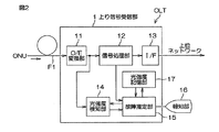
- FIG. 2 shows a configuration of the uplink signal receiving unit 1 of the station side apparatus OLT.
- the upstream signal reception unit 1 includes an O / E conversion unit 11 that converts an optical signal input from the home-side apparatus ONU through the optical fiber F1 into an electrical signal, and a signal processing unit 12 that decodes and processes the converted electrical signal. It has. Furthermore, an interface unit 13 is provided for sending the signal processed by the signal processing unit 12 to a higher-level network.
- the upstream signal receiving unit 1 includes a light intensity detection unit 14 that detects the level of the optical signal from each home-side device ONU, a failure estimation unit 15 that estimates a failure of any home-side device ONU, A notification unit 16 for notifying the system administrator of information on the home-side device ONU in which the failure is estimated with an indicator such as an LED or a liquid crystal display, and further calculating an average value of light intensity received from each home-side device ONU A light intensity storage unit 17 that holds a numerical value is provided.
- a light intensity detection unit 14 that detects the level of the optical signal from each home-side device ONU
- a failure estimation unit 15 that estimates a failure of any home-side device ONU
- a notification unit 16 for notifying the system administrator of information on the home-side device ONU in which the failure is estimated with an indicator such as an LED or a liquid crystal display, and further calculating an average value of light intensity received from each home-side device ONU
- a light intensity storage unit 17 that holds a numerical value is provided.
- the signal processing unit 12 and the failure estimation unit 15 include a processor that performs logical operation processing such as a CPU (Central Processing Unit), an MPU (Micro-Processing Unit), or an FPGA (Field-Programmable Gate Array).
- the signal processing unit 12 and the failure processing unit 15 may be configured by one processor or may be configured by another processor.
- the light intensity detection unit 14 for example, a light measurement circuit (see JP 2011-252716A) including a current mirror circuit, a DC-DC converter, an MPU, and the like can be employed.
- the light intensity storage unit 17 is formed of a memory such as a RAM (Random Access Memory) or a flash memory, for example.
- the O / E conversion unit 11 includes a photoelectric conversion element such as a photodiode, and converts the burst optical signal that has entered from the optical fiber F1 into an electrical signal.
- the received data converted into the electrical signal is synchronized in the signal processing unit 12 and error correction is performed using parity.
- the error-corrected received data is subjected to decoding processing and passed to the upper network through the interface unit.
- the signal processing unit 12 also includes information on the window period of each home-side device ONU (information on which burst optical signal from which home-side device ONU comes in at which time) and information on idle periods (described later) (at which time Information indicating whether or not the idle period is set to the failure estimation unit 15 in advance.
- the signal processing unit 12 and the failure estimation unit 15 need to be moved by a common clock.
- the electric signal converted by the O / E converter 11 is also distributed and supplied to the light intensity detector 14.
- the light intensity detector 14 detects the level of the optical signal from the home device ONU based on the magnitude of the electrical signal.
- the failure estimation unit 15 instructs the light intensity detection unit 14 to start detecting the light intensity from each home-side apparatus ONU at a predetermined time.
- the time at which this instruction is given may be a point in time when the communication of the PON system is normally performed, and can be arbitrarily set by the failure estimation unit 15. For example, immediately after the start-up of the PON system, immediately after a new home-side device ONU joins, a fixed time of the day, or a time determined by the system administrator as appropriate, there is an abnormality in optical communication in the PON system. The time is not found.
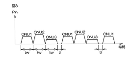
- 5 is a graph showing a waveform of received light intensity Pin of a series of burst optical signals from.
- the number of home-side devices ONU is three, but is not limited to this number (in practice, more home-side devices ONU are connected). However, for the sake of convenience, the description will be given below assuming that the number of home-side devices ONU is three.
- the light intensity detector 14 receives a burst optical signal from the home-side device ONU1, subsequently receives a burst optical signal from the home-side device ONU2, and then receives from the home-side device ONU3. Burst optical signals are received.
- the reception strength from the home side device ONU2 is the strongest, and the reception strength decreases as the home side devices ONU1, 3 are reached. This is seen from the station side device OLT. This is because the characteristics of the light emitting elements of the ONUs 1 to 3 and the characteristics of the optical transmission line such as the length of the optical fiber are different.
- each window period is indicated by “tw”. Between the window period tw and the window period tw, an idle period in which light emission of any home-side apparatus ONU is prohibited is provided. This idle period is indicated by “ti”.
- the original meaning of providing this idle period ti is to take a margin so that the burst optical signals from each home-side apparatus ONU do not overlap.
- the idle period ti is not necessarily provided between adjacent home-side devices ONU and may not be provided (in FIG. 3, between the home-side device ONU1 and the home-side device ONU2, between the home-side device ONU2 and the home-side It is not provided between the devices ONU3 but is provided between the home device ONU3 and the home device ONU1).
- the window period tw is normally about 15 ⁇ sec, while the idle period ti is set within the range of 0 seconds to about 1 ⁇ sec.
- the light intensity detection unit 14 detects during the idle period ti, as can be seen from the definition of the idle period ti that “any home-side device ONU emits light”.
- the intensity of the optical signal should be zero.
- some home-side devices ONU always emit light due to a failure, it is impossible to decode the upstream burst optical signal from other normal home-side devices ONU. In such a case, the intensity of the optical signal detected by the light intensity detector 14 is not zero even during the idle period ti.
- a faulty home-side apparatus ONU is estimated using an optical signal that appears during this idle period.
- a method for estimating a malfunctioning home device will be described.
- the light intensity detection unit 14 detects the intensity of each optical signal through a predetermined low-pass filter built-in at each window period tw in accordance with the light intensity detection start instruction from the failure estimation unit 15. Information on the detected light intensity is passed to the failure estimation unit 15.
- the failure estimation unit 15 digitizes the light intensity.
- the light intensity can be digitized by obtaining, for example, an amplitude envelope of the signal passed from the light intensity detector 14 and A / D converting it.
- the time constant of the low-pass filter of the light intensity detector 14 is preferably selected so that the average level of the optical signal in each window period and idle period can be detected.
- the failure estimation unit 15 writes the light intensity value of the window period tw in the light intensity storage unit 17.
- the light intensity storage unit 17 writes the value of the light intensity in each window period tw together with the time when the light intensity detection unit 14 detects the light intensity by writing from the failure estimation unit 15 in the storage element.
- the handling of the storage history is not limited. For example, when a value is stored at a new time, the old value stored for the window period tw may be deleted, or the window period may be deleted without being deleted. A plurality of values stored for tw may be stored in time series.
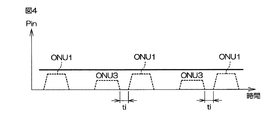
- FIG. 4 shows a waveform of received light intensity Pin of a series of burst optical signals from each home device ONU when any home device ONU always emits light and cannot perform upstream optical communication of the PON communication system. It is a graph which shows. Since the home-side device ONU2 always emits light, as can be seen from the graph of FIG. 4, the light of the faulty home-side device ONU2 is added to the burst optical signal of the other home-side device ONU, and the home-side device The burst optical signals from the ONUs 1 and 3 are hidden by the light of the home-side apparatus ONU2, and are difficult to decipher.
- the failure estimating unit 15 refers to the stored value of the light intensity storage unit 17 when a failure occurs, and executes the following procedure in order to identify the home-side apparatus ONU estimated to be a failure. (1) The failure estimation unit 15 instructs the light intensity detection unit 14 to measure the optical signal intensity during the idle period ti. (2) The failure estimation unit 15 digitizes the light intensity measured by the light intensity detection unit 14 and temporarily stores it in a buffer area in the failure estimation unit 15.
- the failure estimation unit 15 compares the optical signal intensity in the idle period ti with the value of the optical intensity of each home device ONU stored in the optical intensity storage unit 17 when the PON system is normal. (4) The difference between the optical signal intensity value of each home-side apparatus ONU stored in the light intensity storage unit 17 and the value of the light intensity in the idle period ti is taken, and either difference is greater than a predetermined threshold value. When it becomes small, the home side apparatus ONU is estimated to be a home side apparatus ONU that seems to emit light constantly.
- each home-side device ONU is listed as a candidate for a faulty home-side device ONU.
- the station-side apparatus OLT takes measures to increase the accuracy of failure determination for one or more home-side apparatuses ONU that are estimated to be always emitting light. Specifically, a DPoE OAM message (referred to as extinction / emission command) for controlling the extinction / emission of light output is transmitted to the one or more candidate home-side devices ONU to stop the emission.
- DPoE Docsis Providing of EPON
- OAM Operaation Administration and Maintenance
- This extinction / light emission command is also effective for a home-side device ONU that is always emitting light due to a failure.
- the signal processing unit 12 can decode a signal from the home side device ONU other than the one or more candidate home side devices ONU, the one home side device ONU fails. It can be determined that Alternatively, any of the plurality of candidate home-side devices ONUs can be determined to be a faulty ONU.
- a DPoE OAM message (0xD9 / 0x0605) is transmitted to the plurality of candidate home-side devices ONU Relight one by one.
- the first home-side device ONU is re-emitted, when the signal processing unit 12 can normally read the contents of the optical signal for the other home-side device ONU, the first home-side device ONU emits abnormal light. It can be determined that the failure is not a failure ONU. In this way, the second, third,...
- a certain home-side device ONU is caused to emit light again, if the contents of the optical signal cannot be read normally for another home-side device ONU, it can be determined that the home-side device ONU is a faulty ONU that emits abnormal light.
- the home-side apparatus ONU that seems to emit light constantly can be estimated by the procedures (1) to (5). Since the extinction / emission command is transmitted only to the estimated home-side apparatus ONU as shown in (6) and (7), everything in the PON system as in the conventional method described in Patent Document 1 Compared with the method of transmitting the extinction / light emission command to the home-side device ONU, the time required to find the home-side device ONU that emits abnormal light is shortened. This is because it is not necessary to issue an extinction / emission command to the normal home side device ONU that is not always emitting light in the procedures (1) to (5), so that the search time can be saved. is there.
- the specified home device ONU is displayed on the notification unit 16 and notified to the system administrator by an alarm function such as SNMP Trap or e-mail. It can be urged to go to the site of the device ONU for inspection.
Landscapes
- Engineering & Computer Science (AREA)
- Physics & Mathematics (AREA)
- Electromagnetism (AREA)
- Computer Networks & Wireless Communication (AREA)
- Signal Processing (AREA)
- Computing Systems (AREA)
- Small-Scale Networks (AREA)
- Optical Communication System (AREA)
Abstract
本発明の実施形態に係る方法は、連続信号を出し続ける故障の発生した宅側装置ONUを特定できる故障端末特定方法に関する。この方法では、PON通信システムに接続されている複数の宅側装置ONUに対して上りバースト光信号送信のタイミングを指定し、各宅側装置ONUから送信されてくる上りバースト光信号の強度をあらかじめ検知して記憶し、どの宅側装置ONUに対しても上りバースト光信号の送信を指定していない時間tiに検知される光信号の強度を異常光強度として認識し、前記異常光強度を、前記記憶した各宅側装置ONUの上りバースト光信号強度とそれぞれ比較し、前記比較の結果、光強度の差がしきい値よりも小さな1又は複数の宅側装置ONUを、連続信号を出し続ける故障の発生した宅側装置ONU又はその候補であると推定する。
Description
本発明は、局側装置と複数の宅側装置との間を結ぶ光データ通信ネットワーク、特にPON(Passive Optical Network)通信システムにおいて、宅側装置の故障を特定する技術に関するものである。
局側装置OLT(Optical Line Terminal:光加入者線端局装置)と、複数の宅側装置ONU(Optical Network Unit:光加入者線終端装置)との間を、光データ通信ネットワークを使って双方向通信するシステムがあり、特に、局側装置OLTと各宅側装置ONUとの間を、それぞれ1本の光ファイバで放射状に結ぶ(Single Star)ネットワーク構成が古くから実用化されている。このネットワーク構成では、システム及び機器構成は簡単になるが、1つの宅側装置ONUが一本の光ファイバを占有し、宅側装置ONU数がN局あれば、局側装置OLTから直接接続される光ファイバがN本必要となり、システムの低価格化を図るのが困難である。
そこで、局側装置OLTから引かれる1本の光ファイバを、複数の宅側装置ONUで共有するPON通信システムが実用化されている。
PON通信システムでは、特に外部からの電源供給を必要とせず入力された信号から受動的(Passive)に信号を分岐・多重する受動型光分岐器(光カプラ;OC)を介して、一つの局側装置OLTと複数の宅側装置ONUが光伝送路で接続される。局側装置OLTとN局の宅側装置ONUとは、光ファイバ及び光カプラOCを介して接続された1対Nの伝送を基本としている。これにより、1つの局側装置OLTに対して、多くの宅側装置ONUを割り当てることができ、全体的な設備コストを抑えることができる。
PON通信システムでは、特に外部からの電源供給を必要とせず入力された信号から受動的(Passive)に信号を分岐・多重する受動型光分岐器(光カプラ;OC)を介して、一つの局側装置OLTと複数の宅側装置ONUが光伝送路で接続される。局側装置OLTとN局の宅側装置ONUとは、光ファイバ及び光カプラOCを介して接続された1対Nの伝送を基本としている。これにより、1つの局側装置OLTに対して、多くの宅側装置ONUを割り当てることができ、全体的な設備コストを抑えることができる。
PON通信システムでは、局側装置OLTと光分岐器間の光伝送路を複数の宅側装置ONUで共有するため、宅側装置ONUから局側装置OLTに向かう方向(以下、上り方向と称する)において、各宅側装置ONUが送出する光信号の衝突回避対策が必要である。このため、局側装置OLTが時分割アクセス制御方式により各宅側装置ONUの光信号送出タイミングを制御している。
この時分割アクセス制御方式により、各宅側装置ONUは、局側装置OLTにより指定されたある区切られた時間に光信号を送出する。このように各宅側装置ONUから送出される光信号を「バースト光信号」と呼ぶ。
このように、PON通信システム上で1台の局側装置OLTに複数の宅側装置ONUがつながっているため、いずれかの宅側装置ONUが常時点灯状態になる故障を起こすと、他の宅側装置ONUからの光信号に重なってしまい、他の残りの宅側装置ONUとも通信を行うことが困難になるという障害が発生する。この場合、局側装置OLTのシステム管理者が点灯状態の宅側装置ONUを何らかの手段で特定して、常時点灯の故障が発生した宅側装置ONUを修理又は交換する必要がある。
このように、PON通信システム上で1台の局側装置OLTに複数の宅側装置ONUがつながっているため、いずれかの宅側装置ONUが常時点灯状態になる故障を起こすと、他の宅側装置ONUからの光信号に重なってしまい、他の残りの宅側装置ONUとも通信を行うことが困難になるという障害が発生する。この場合、局側装置OLTのシステム管理者が点灯状態の宅側装置ONUを何らかの手段で特定して、常時点灯の故障が発生した宅側装置ONUを修理又は交換する必要がある。
しかし常時点灯状態では、局側装置OLTは、各宅側装置ONUからの上りパケットの識別ができないので、点灯状態の宅側装置ONUを特定するのに工夫が必要である。
特許文献1においては、局側装置OLTが順次宅側装置ONUに消光命令を出すことで宅側装置ONUの発光を停止させ、故障のある宅側装置ONUを特定するという、障害復旧手順を定めている。
特許文献1においては、局側装置OLTが順次宅側装置ONUに消光命令を出すことで宅側装置ONUの発光を停止させ、故障のある宅側装置ONUを特定するという、障害復旧手順を定めている。
特許文献2においては、局側装置OLTにおいて、各宅側装置ONUの上りバースト光信号強度をあらかじめ検知しておき、障害が発生した時に、各宅側装置ONUの上りバースト光信号強度をそれぞれ再検知し、同じ宅側装置ONU同士で故障前後の光強度を比較し、障害発生前後で光強度の変化が最も小さい宅側装置ONUを、連続信号を出し続ける故障の発生した宅側装置ONUであると判定する。
この特許文献2においては、いずれかの宅側装置ONUが常時点灯すると、その故障以外の宅側装置ONUからの光信号強度は、当該の宅側装置ONUの光信号強度に前記故障の宅側装置ONUの光信号強度が上乗せされたものとなり、光信号強度が増大する。しかし故障の宅側装置ONUの光信号強度はそのままである。したがって、故障判定部14は、各宅側装置ONUからの光信号強度を測定して、それらの測定結果を記憶しておき、障害発生前後で光強度の変化が小さい順に、故障宅側装置ONUの候補を決定する。これにより、連続信号を出し続ける故障宅側装置ONUを特定することができる。
ところが、特許文献1においては、局側装置OLTに接続されている宅側装置ONUの台数が多い場合、故障している宅側装置ONUを切り分けるまでひとつずつ確認の手順を行う必要があり、復旧に時間がかかる。
また、特許文献2においては、各故障宅側装置ONUからの光信号強度を測定して、現在(故障時)の光信号強度と過去(正常時)に測定した光信号強度とを、宅側装置ONUごとに比較しなければならない。このため、宅側装置ONUの数だけ比較を行う必要があり、宅側装置ONUの台数に応じて、時間あるいはコストがかかる。
また、特許文献2においては、各故障宅側装置ONUからの光信号強度を測定して、現在(故障時)の光信号強度と過去(正常時)に測定した光信号強度とを、宅側装置ONUごとに比較しなければならない。このため、宅側装置ONUの数だけ比較を行う必要があり、宅側装置ONUの台数に応じて、時間あるいはコストがかかる。
そこで本発明は、局側装置と、前記局側装置と光カプラを介して接続される複数の宅側装置とを含むPON通信システムにおいて、先行技術よりも、より簡単な処理を行うだけで、連続信号を出し続ける故障の発生した宅側装置を特定できる局側装置及び故障端末特定方法を提供することを目的とする。
本発明のPON通信システムにおける局側装置は、各宅側装置から送信されてくる上りバースト光信号の強度をそれぞれ検知する光強度検知部と、前記検知された光強度が宅側装置ごとに書き込まれる光強度記憶部と、どの宅側装置に対しても上りバースト光信号の送信を指定していない時間に検知された光信号の強度を異常光強度として認識し、前記異常光強度を、前記光強度記憶部に書き込まれた各宅側装置の上りバースト光信号の強度とそれぞれ比較し、前記比較の結果、光強度の差がしきい値よりも小さい1若しくは複数の宅側装置を、連続信号を出し続ける故障の発生した宅側装置又はその候補であると推定する故障推定部とを備えるものである。
この局側装置であれば、前記複数の宅側装置に対して上りバースト光信号送信のタイミングを指定して、各宅側装置から送信されてくる上りバースト光信号強度をあらかじめ検知して記憶しておき、どの宅側装置に対しても上りバースト光信号の送信を指定していない時間に検知される光信号の強度を異常光強度として認識し、前記認識した異常光強度を、記憶した各宅側装置の上りバースト光信号強度とそれぞれ比較し、前記比較の結果、光強度の差がしきい値よりも小さい宅側装置を、連続信号を出し続ける故障の発生した宅側装置であると推定することができる。
また前記比較の結果、光強度の差の小さな宅側装置が複数あり、故障の発生した宅側装置を明確に決定し難い場合は、光強度の差がしきい値よりも小さいものを複数の故障宅側装置の候補とする。これにより、PON通信システムに接続されたすべての宅側装置の中から、故障の発生が疑われる宅側装置を絞ることができる。
前記光強度検知部が、各宅側装置からの上りバースト光信号の強度をあらかじめ検知しておくタイミングは、すべての宅側装置と正常に通信している時であることが望ましい。
前記光強度検知部が、各宅側装置からの上りバースト光信号の強度をあらかじめ検知しておくタイミングは、すべての宅側装置と正常に通信している時であることが望ましい。
前記故障推定部は、前記推定された1又は複数の宅側装置に対してのみ消光/発光コマンドを出すことによって、常時発光状態を検知する宅側装置ONUを故障の発生した宅側装置であると、短時間で特定することができる。
また本発明のPON通信システムにおける故障端末特定方法は、前記PON通信システムにおける局側装置の発明と実質同一発明に係る方法である。
また本発明のPON通信システムにおける故障端末特定方法は、前記PON通信システムにおける局側装置の発明と実質同一発明に係る方法である。
以上のように本発明によれば、局側装置において、連続信号を出し続ける故障した宅側装置を推定することができ、すみやかに故障した宅側装置の特定作業に入ることができるという効果が得られる。
以下、本発明の実施の形態について、添付図面を参照して説明する。
図1は、PON通信システムの構成例を示す概略図である。
PON通信システムは、複数の加入者宅に備えられる各宅側装置ONUが、局舎に備えられる局側装置OLTに対して、幹線光ファイバF1、光カプラOC1,OC2、支線光ファイバF2を介してツリー状に接続されている。
図1は、PON通信システムの構成例を示す概略図である。
PON通信システムは、複数の加入者宅に備えられる各宅側装置ONUが、局舎に備えられる局側装置OLTに対して、幹線光ファイバF1、光カプラOC1,OC2、支線光ファイバF2を介してツリー状に接続されている。
すなわち局側装置OLTは、幹線光ファイバF1を通して光カプラOC1に接続され、光カプラOC1は、1又は複数台の宅側装置ONUと接続されるとともに、1又は複数台の第2の光カプラOC2と接続されている。第2の光カプラOC2は、複数台の宅側装置ONUに、支線光ファイバF2で接続されている。
なお、ネットワークのツリーの分岐点となる光カプラOCの数は、図1では2つ示しているが、”2”に限られるものではない。光カプラOCの数は1以上であれば、いくらであっても良い。接続される宅側装置ONUの数も限定されない。
なお、ネットワークのツリーの分岐点となる光カプラOCの数は、図1では2つ示しているが、”2”に限られるものではない。光カプラOCの数は1以上であれば、いくらであっても良い。接続される宅側装置ONUの数も限定されない。
幹線光ファイバF1と、支線光ファイバF2とは、それぞれ1本のシングルモードファイバを用いている。光カプラOCは、特に外部からの電源供給を必要とせず入力された信号から受動的に信号を分岐・多重するスターカプラで構成されている。
宅側装置ONUは、加入者宅内に設置されるパーソナルコンピュータやテレビなどの光ネットワークサービスを享受するための端末機器を接続するネットワークインタフェースを備えている。
宅側装置ONUは、加入者宅内に設置されるパーソナルコンピュータやテレビなどの光ネットワークサービスを享受するための端末機器を接続するネットワークインタフェースを備えている。
上り回線と下り回線とは異なる波長の光を用いており、上下での信号の衝突は起きない仕組みとなっている。よって、局側装置OLTが送信する信号は、光カプラOC1、第2の光カプラOC2を通して、複数台の宅側装置ONUに分配され、各宅側装置ONUが送信する信号は、局側装置OLTに集められる。
上位のネットワークから局側装置OLTに入ってくる信号に含まれる下りフレームは、局側装置OLTにおいて所定の処理が行われ、中継されるべき論理リンクが特定される。そして、局側装置OLTを通して、光信号として幹線光ファイバF1に送信される。幹線光ファイバF1に送信された光信号は、光カプラOCで分岐され、光カプラOCにつながる宅側装置ONUに送信されるが、当該論理リンクを構成する宅側装置ONUのみが所定の光信号を取り込むことができ、フレームを宅内ネットワークインタフェースに中継する。
上位のネットワークから局側装置OLTに入ってくる信号に含まれる下りフレームは、局側装置OLTにおいて所定の処理が行われ、中継されるべき論理リンクが特定される。そして、局側装置OLTを通して、光信号として幹線光ファイバF1に送信される。幹線光ファイバF1に送信された光信号は、光カプラOCで分岐され、光カプラOCにつながる宅側装置ONUに送信されるが、当該論理リンクを構成する宅側装置ONUのみが所定の光信号を取り込むことができ、フレームを宅内ネットワークインタフェースに中継する。
一方、上り光信号には、それぞれの宅側装置ONUからの上りフレームが含まれている。上りフレームは、それぞれの宅側装置ONUからの上りフレームどうしが互いに時間的に競合しないように送信される必要がある。そのために、局側装置OLTは、各宅側装置ONUに対して上り光信号を送信してもよいウィンドウ期間(以下、ウィンドウあるいはタイミングということがある)を順番に割り当てる。局側装置OLTは、その割当て情報を制御フレームとして通知する。ウィンドウを割り当てられた宅側装置ONUは、自己に割り当てられたウィンドウに上り光信号を送信する。この方法は一種の時分割多重方式であり、各宅側装置ONUから送出される上り光信号を「バースト光信号」という。
このようにして、各宅側装置ONU間の上り光信号の競合は回避される。各宅側装置ONUはあるウィンドウが与えられたとき、そのウィンドウに収まる限り複数のフレームを連続して送信してもよい。
図2に、局側装置OLTの上り信号受信部1の構成を示す。上り信号受信部1は、光ファイバF1を通して宅側装置ONUから入ってくる光信号を電気信号に変換するO/E変換部11と、変換された電気信号を解読し処理する信号処理部12とを備えている。さらに信号処理部12によって処理された信号を上位のネットワークに送り出すためのインターフェイス部13を備えている。
図2に、局側装置OLTの上り信号受信部1の構成を示す。上り信号受信部1は、光ファイバF1を通して宅側装置ONUから入ってくる光信号を電気信号に変換するO/E変換部11と、変換された電気信号を解読し処理する信号処理部12とを備えている。さらに信号処理部12によって処理された信号を上位のネットワークに送り出すためのインターフェイス部13を備えている。
上り信号受信部1はこれに加えて、各宅側装置ONUからの光信号のレベルを検知する光強度検知部14と、いずれかの宅側装置ONUの故障を推定する故障推定部15と、故障が推定された宅側装置ONUの情報をLED、液晶表示器などのインジケータでシステム管理者に報知する報知部16とを備え、さらに各宅側装置ONUから受信される光強度の平均値を数値化した値を保持する光強度記憶部17を備えている。
信号処理部12及び故障推定部15は、例えば、CPU(Central Processing Unit)、MPU(Micro-Processing Unit)又はFPGA(Field-Programmable Gate Array)などの、論理演算処理を行うプロセッサを含む。信号処理部12及び故障処理部15は、1つのプロセッサで構成されていてもよいし、別のプロセッサで構成されていてもよい。
光強度検知部14としては、例えば、電流ミラー回路、DC-DCコンバータ及びMPUなどを備えた光測定回路(特開2011-252716号公報参照)を採用することができる。
光強度記憶部17は、例えば、RAM(Random Access Memory)又はフラッシュメモリなどのメモリよりなる。
光強度記憶部17は、例えば、RAM(Random Access Memory)又はフラッシュメモリなどのメモリよりなる。
前記O/E変換部11は、フォトダイオードなどの光電変換素子を備え、光ファイバF1から入ってきたバースト光信号を電気信号に変換する。電気信号に変換された受信データは、信号処理部12において同期をとられ、パリティを用いて誤り訂正が行われる。誤り訂正された受信データは、復号処理が行われ、インターフェイス部を通して上位ネットワークへ渡される。
また信号処理部12は、各宅側装置ONUのウィンドウ期間の情報(どの時刻にどの宅側装置ONUからのバースト光信号が入ってくるかという情報)及びアイドル期間(後述)の情報(どの時刻にアイドル期間が設定されているかという情報)を、故障推定部15に通知しておく。その前提として信号処理部12と故障推定部15とは共通の時計で動いている必要がある。
前記O/E変換部11によって変換された電気信号は、光強度検知部14にも分配供給される。光強度検知部14は、電気信号の大きさに基づいて、宅側装置ONUからの光信号のレベルを検知する。
故障推定部15は、光強度検知部14に、所定の時刻になれば各宅側装置ONUからの光強度の検知を開始するように指示を与える。この指示を与える時刻は、PONシステムの通信が正常に行われている時点であればよく、故障推定部15が任意に設定することができる。例えば、PONシステムの立ち上げ直後、宅側装置ONUが新規に加入した直後、一日のうち決まった時刻、あるいはシステム管理者が適宜判断した時刻などであり、PONシステム内の光通信に異常が発見されない時刻である。
故障推定部15は、光強度検知部14に、所定の時刻になれば各宅側装置ONUからの光強度の検知を開始するように指示を与える。この指示を与える時刻は、PONシステムの通信が正常に行われている時点であればよく、故障推定部15が任意に設定することができる。例えば、PONシステムの立ち上げ直後、宅側装置ONUが新規に加入した直後、一日のうち決まった時刻、あるいはシステム管理者が適宜判断した時刻などであり、PONシステム内の光通信に異常が発見されない時刻である。
図3は、故障推定部15から光強度の検知を開始するように指示が与えられた時刻(時刻t=0とする)から始まる、光強度検知部14によって検知される、各宅側装置ONUからの一連のバースト光信号の受信光強度Pinの波形を示すグラフである。図3では宅側装置ONUの数を3つ示しているが、この数に限られない(実際には、もっと多くの宅側装置ONUが接続される)。しかし以下では便宜上、宅側装置ONUの数を3つとして説明を進める。
図3に示すように、光強度検知部14には、宅側装置ONU1からのバースト光信号が受信され、続いて宅側装置ONU2からのバースト光信号が受信され、続いて宅側装置ONU3からのバースト光信号が受信される。図3では、宅側装置ONU2からの受信強度が一番強く、宅側装置ONU1,3となるに連れて受信強度が弱くなっているが、これは局側装置OLTから見て、宅側装置ONU1~3の発光素子の特性や、光ファイバの長さなどの光伝送路の特性が異なるからである。
局側装置OLTが宅側装置ONUにウィンドウ期間を割り当てるとき、局側装置OLTは、どの宅側装置ONUも発光してはいけないという「アイドル期間」を設定し、各宅側装置ONUに通知するようにしている。
図3に、各ウィンドウ期間を”tw”で示す。ウィンドウ期間twとウィンドウ期間twとの間に、どの宅側装置ONUの発光も禁止するアイドル期間が設けられている。このアイドル期間を、”ti”で示す。
図3に、各ウィンドウ期間を”tw”で示す。ウィンドウ期間twとウィンドウ期間twとの間に、どの宅側装置ONUの発光も禁止するアイドル期間が設けられている。このアイドル期間を、”ti”で示す。
このアイドル期間tiを設ける本来の意味は、各宅側装置ONUからのバースト光信号が重複しないようにマージンをとることである。アイドル期間tiは隣接する宅側装置ONUの間に絶対設ける必要があるものではなく、設けない場合もある(図3では宅側装置ONU1と宅側装置ONU2の間、宅側装置ONU2と宅側装置ONU3の間には設けられていないが、宅側装置ONU3と宅側装置ONU1の間には設けられている)。ウィンドウ期間twが通常、約15μ秒であるのに対して、アイドル期間tiは、0秒から約1μ秒の範囲内で設定される。
PONシステムの通信が正常に行われていれば、「どの宅側装置ONUの発光も禁止する」というアイドル期間tiの定義からわかるように、アイドル期間tiの間、光強度検知部14が検知する光信号の強度はゼロであるはずである。
しかし故障により、一部の宅側装置ONUが常時発光するようになれば、他の正常な宅側装置ONUからの上りバースト光信号を解読することができなくなる。このような場合、アイドル期間tiの間でも、光強度検知部14が検知する光信号の強度はゼロでなくなる。本発明では、このアイドル期間に現れる光信号を利用して、故障している宅側装置ONUを推定する。以下、故障している宅側装置を推定する方法を説明する。
しかし故障により、一部の宅側装置ONUが常時発光するようになれば、他の正常な宅側装置ONUからの上りバースト光信号を解読することができなくなる。このような場合、アイドル期間tiの間でも、光強度検知部14が検知する光信号の強度はゼロでなくなる。本発明では、このアイドル期間に現れる光信号を利用して、故障している宅側装置ONUを推定する。以下、故障している宅側装置を推定する方法を説明する。
光強度検知部14では、故障推定部15からの光強度検知開始の指示に従って、各ウィンドウ期間twの時点において、内蔵する所定のローパスフィルタを通して、各光信号強度を検知する。検知した光強度の情報は故障推定部15に渡される。故障推定部15は光強度の数値化を行う。前記光強度の数値化は、光強度検知部14から渡される信号の、例えば振幅の包絡線を求め、それをA/D変換することで実施できる。
なお、光強度検知部14の前記ローパスフィルタの時定数は、各ウィンドウ期間及びアイドル期間における光信号の平均レベルが検知できるように、最適のものを選択しておくとよい。
故障推定部15は、ウィンドウ期間twの光強度の値を光強度記憶部17に書き込む。 光強度記憶部17は故障推定部15からの書き込みにより、各ウィンドウ期間twにおける光強度の値を、光強度検知部14が光強度を検知した時刻とともに記憶素子に書き込む。記憶の履歴の扱いについては限定されないが、例えば新しい時刻に値が記憶されると、そのウィンドウ期間twについて記憶された古い値を消去するようにしてもよいし、消去せずに、そのウィンドウ期間twについて記憶された複数の値を時系列に記憶するようにしてもよい。
故障推定部15は、ウィンドウ期間twの光強度の値を光強度記憶部17に書き込む。 光強度記憶部17は故障推定部15からの書き込みにより、各ウィンドウ期間twにおける光強度の値を、光強度検知部14が光強度を検知した時刻とともに記憶素子に書き込む。記憶の履歴の扱いについては限定されないが、例えば新しい時刻に値が記憶されると、そのウィンドウ期間twについて記憶された古い値を消去するようにしてもよいし、消去せずに、そのウィンドウ期間twについて記憶された複数の値を時系列に記憶するようにしてもよい。
図4は、いずれかの宅側装置ONUが常時発光して、PON通信システムの上り光通信が行えなくなった場合の、各宅側装置ONUからの一連のバースト光信号の受信光強度Pinの波形を示すグラフである。
宅側装置ONU2が常時発光しているので、図4のグラフからわかるように、その故障している宅側装置ONU2の光が他の宅側装置ONUのバースト光信号に上乗せされ、宅側装置ONU1,3からのバースト光信号は宅側装置ONU2の光に隠れてしまい、解読が困難な状態になっている。
宅側装置ONU2が常時発光しているので、図4のグラフからわかるように、その故障している宅側装置ONU2の光が他の宅側装置ONUのバースト光信号に上乗せされ、宅側装置ONU1,3からのバースト光信号は宅側装置ONU2の光に隠れてしまい、解読が困難な状態になっている。
そこで、故障推定部15は、障害発生時に光強度記憶部17の記憶値を参照して、故障と推定される宅側装置ONUを特定するため、次のような手順を実行する。
(1)故障推定部15は、光強度検知部14に、アイドル期間tiにおいて光信号強度を測定するように指示する。
(2)故障推定部15は、光強度検知部14で測定された光強度の数値化を行い、故障推定部15内のバッファ領域に一時的に蓄える。
(1)故障推定部15は、光強度検知部14に、アイドル期間tiにおいて光信号強度を測定するように指示する。
(2)故障推定部15は、光強度検知部14で測定された光強度の数値化を行い、故障推定部15内のバッファ領域に一時的に蓄える。
(3)故障推定部15は、アイドル期間tiにおける光信号強度について、光強度記憶部17に記憶されたPONシステム正常時の各宅側装置ONUの光強度の値と比較する。
(4)光強度記憶部17に記憶された各宅側装置ONUの光信号強度値と、アイドル期間tiにおける光強度の値との差をとり、いずれかの差が所定のしきい値よりも小さくなった場合、その宅側装置ONUを、常時発光しているらしい宅側装置ONUであると推定する。
(4)光強度記憶部17に記憶された各宅側装置ONUの光信号強度値と、アイドル期間tiにおける光強度の値との差をとり、いずれかの差が所定のしきい値よりも小さくなった場合、その宅側装置ONUを、常時発光しているらしい宅側装置ONUであると推定する。
(5)ただしアイドル期間tiにおける光強度の値と、光強度記憶部17に記憶された各宅側装置ONUの光信号強度との差がしきい値よりも小さくなる宅側装置ONUが複数ある場合、それぞれの宅側装置ONUを、故障した宅側装置ONUの候補としてあげておく。
(6)局側装置OLTは、常時発光しているらしいと推定された1又は複数の宅側装置ONUについて、故障判定の精度を高める措置をとる。具体的には、当該1又は複数の候補の宅側装置ONUに、光出力の消光/発光を制御するDPoE OAMメッセージ(消光/発光コマンドという)を送信し、発光を停止させる。ここでDPoE(Docsis Providing of EPON)とは、ケーブルテレビ事業者が伝送路を従来の同軸ケーブルから光ファイバに置き換えた高速通信サービスを提供するために標準化した規格を意味する。OAM(Operation Administration and Maintenance)とは、局側装置OLTが宅側装置ONUを制御するメッセージを意味する。
(6)局側装置OLTは、常時発光しているらしいと推定された1又は複数の宅側装置ONUについて、故障判定の精度を高める措置をとる。具体的には、当該1又は複数の候補の宅側装置ONUに、光出力の消光/発光を制御するDPoE OAMメッセージ(消光/発光コマンドという)を送信し、発光を停止させる。ここでDPoE(Docsis Providing of EPON)とは、ケーブルテレビ事業者が伝送路を従来の同軸ケーブルから光ファイバに置き換えた高速通信サービスを提供するために標準化した規格を意味する。OAM(Operation Administration and Maintenance)とは、局側装置OLTが宅側装置ONUを制御するメッセージを意味する。
この消光/発光コマンドは、故障して常時発光している宅側装置ONUに対しても有効である。この発光を停止させたとき、当該1又は複数の候補の宅側装置ONU以外の宅側装置ONUからの信号が信号処理部12によって解読できるようになれば、当該1の宅側装置ONUが故障であると判定することができる。または、当該複数の候補の宅側装置ONUのいずれかが故障ONUであると判定することができる。
(7)当該複数の候補の宅側装置ONUのいずれかが故障ONUであると判定された場合、そのあと、当該複数の候補の宅側装置ONUにDPoE OAMメッセージ(0xD9/0x0605)を送信し、1つずつ再発光させる。まず一番目の宅側装置ONUを再発光させたとき、他の宅側装置ONUについて信号処理部12によって光信号の内容が正常に読めるときは、当該第一番目の宅側装置ONUは異常発光する故障ONUでないと判定することができる。このようにして二番目、三番目・・・の宅側装置ONUを再発光させていく。ある宅側装置ONUを再発光させたとき、他の宅側装置ONUについて光信号の内容が正常に読めなくなれば、当該宅側装置ONUは異常発光する故障ONUであると判定することができる。
このように、前記(1)~(5)の手順によって、常時発光しているらしい宅側装置ONUを推定できる。
その推定された宅側装置ONUに対してのみ、(6)(7)のように消光/発光コマンドを送信するので、特許文献1に記載された従来の手法のように、PONシステムにあるすべての宅側装置ONUに対して消光/発光コマンドを送信する手法と比べて、異常発光している宅側装置ONUを発見するのに要する時間が短くなる。これは、(1)~(5)の手順で常時発光していないとされた正常宅側装置ONUに対しては、消光/発光コマンドを出さなくて済むので、それだけ探索時間が節約できるからである。
その推定された宅側装置ONUに対してのみ、(6)(7)のように消光/発光コマンドを送信するので、特許文献1に記載された従来の手法のように、PONシステムにあるすべての宅側装置ONUに対して消光/発光コマンドを送信する手法と比べて、異常発光している宅側装置ONUを発見するのに要する時間が短くなる。これは、(1)~(5)の手順で常時発光していないとされた正常宅側装置ONUに対しては、消光/発光コマンドを出さなくて済むので、それだけ探索時間が節約できるからである。
(8)故障の宅側装置ONUを特定したあと、特定された宅側装置ONUを報知部16に表示させ、SNMP Trap等の警報機能、電子メールなどでシステム管理者に通知して、宅側装置ONUの現場に行き点検をするように促すことができる。
以上で、本発明の実施の形態の説明をしたが、本発明の実施は、前記の形態に限定されるものではなく、本発明の範囲内で種々の変更を施すことが可能である。
以上で、本発明の実施の形態の説明をしたが、本発明の実施は、前記の形態に限定されるものではなく、本発明の範囲内で種々の変更を施すことが可能である。
1 上り信号受信部
11 O/E変換部
12 信号処理部
13 インターフェイス部
14 光強度検知部
15 故障推定部
16 報知部
17 光強度記憶部
11 O/E変換部
12 信号処理部
13 インターフェイス部
14 光強度検知部
15 故障推定部
16 報知部
17 光強度記憶部
Claims (4)
- 局側装置と、前記局側装置と光カプラを介して接続される複数の宅側装置とを含むPON(Passive Optical Network)通信システムに用いられる局側装置であって、
各宅側装置から送信されてくる上りバースト光信号の強度をそれぞれ検知する光強度検知部と、
前記検知された光強度が宅側装置ごとに書き込まれる光強度記憶部と、
どの宅側装置に対しても上りバースト光信号の送信を指定していない時間に検知された光信号の強度を異常光強度として認識し、前記異常光強度を、前記光強度記憶部に書き込まれた各宅側装置の上りバースト光信号の強度とそれぞれ比較し、前記比較の結果、光強度の差がしきい値よりも小さい1若しくは複数の宅側装置を、連続信号を出し続ける故障の発生した宅側装置又はその候補であると推定する故障推定部とを備える、局側装置。 - 前記光強度記憶部に書き込まれる光強度は、すべての宅側装置と正常に通信している時に前記光強度検知部があらかじめ検知する、各宅側装置からの上りバースト光信号の強度である、請求項1に記載の局側装置。
- 前記故障推定部は、前記推定された1又は複数の宅側装置に対して、消光/発光コマンドを出すことによって、常時発光状態を検知した宅側装置を故障の発生した宅側装置であると特定する、請求項1又は請求項2に記載の局側装置。
- 局側装置と、前記局側装置と光カプラを介して接続される複数の宅側装置とを含むPON(Passive Optical Network)通信システムに用いられる局側装置において、故障している宅側装置を推定する方法であって、
前記複数の宅側装置に対して上りバースト光信号送信のタイミングを指定し、
各宅側装置から送信されてくる上りバースト光信号強度をあらかじめ検知して記憶し、
どの宅側装置に対しても上りバースト光信号の送信を指定していない時間に検知される光信号の強度を異常光強度として認識し、
前記異常光強度を、前記記憶した各宅側装置の上りバースト光信号強度とそれぞれ比較し、
前記比較の結果、光強度の差がしきい値よりも小さな1又は複数の宅側装置を、連続信号を出し続ける故障の発生した宅側装置又はその候補であると推定する、故障端末特定方法。
Priority Applications (2)
| Application Number | Priority Date | Filing Date | Title |
|---|---|---|---|
| US15/571,281 US20180359028A1 (en) | 2015-05-08 | 2016-01-15 | Optical line terminal and failed terminal identification method for pon communication system |
| CA2985162A CA2985162A1 (en) | 2015-05-08 | 2016-01-15 | Optical line terminal and failed terminal identification method for pon communication system |
Applications Claiming Priority (2)
| Application Number | Priority Date | Filing Date | Title |
|---|---|---|---|
| JP2015095913A JP6376404B2 (ja) | 2015-05-08 | 2015-05-08 | Pon通信システムにおける局側装置及び故障端末特定方法 |
| JP2015-095913 | 2015-05-08 |
Publications (1)
| Publication Number | Publication Date |
|---|---|
| WO2016181666A1 true WO2016181666A1 (ja) | 2016-11-17 |
Family
ID=57248769
Family Applications (1)
| Application Number | Title | Priority Date | Filing Date |
|---|---|---|---|
| PCT/JP2016/051109 Ceased WO2016181666A1 (ja) | 2015-05-08 | 2016-01-15 | Pon通信システムにおける局側装置及び故障端末特定方法 |
Country Status (4)
| Country | Link |
|---|---|
| US (1) | US20180359028A1 (ja) |
| JP (1) | JP6376404B2 (ja) |
| CA (1) | CA2985162A1 (ja) |
| WO (1) | WO2016181666A1 (ja) |
Families Citing this family (7)
| Publication number | Priority date | Publication date | Assignee | Title |
|---|---|---|---|---|
| CN106549706B (zh) * | 2015-09-16 | 2019-04-26 | 青岛海信宽带多媒体技术有限公司 | 一种电口模块 |
| CN112118499B (zh) * | 2019-06-19 | 2023-07-21 | 中兴通讯股份有限公司 | 光网络单元onu掉电告警方法、装置、设备及存储介质 |
| US11184692B2 (en) * | 2020-03-13 | 2021-11-23 | Verizon Patent And Licensing Inc. | Systems and methods for measurement of optical parameters in an optical network |
| CN113794957B (zh) * | 2021-08-15 | 2023-12-26 | 新华三信息安全技术有限公司 | 一种实现光网络单元地理显示的方法、系统及设备 |
| CN113727223B (zh) * | 2021-08-18 | 2023-11-03 | 烽火通信科技股份有限公司 | 一种上行数据发送方法、异常发光检测方法、设备及系统 |
| CN115733545A (zh) * | 2021-08-31 | 2023-03-03 | 中国移动通信集团吉林有限公司 | 一种分光器性能异常检测方法及装置 |
| CN119450265A (zh) * | 2023-07-31 | 2025-02-14 | 中兴通讯股份有限公司 | 光网络冲突检测方法、装置及存储介质 |
Citations (4)
| Publication number | Priority date | Publication date | Assignee | Title |
|---|---|---|---|---|
| JP2002359596A (ja) * | 2001-05-30 | 2002-12-13 | Mitsubishi Electric Corp | バースト光出力監視方法および装置 |
| JP2006303673A (ja) * | 2005-04-18 | 2006-11-02 | Matsushita Electric Ind Co Ltd | 光加入者システム及び該光加入者システムにおける妨害光源推定方法 |
| JP2008104028A (ja) * | 2006-10-19 | 2008-05-01 | Fujitsu Ltd | 異常onu特定装置、異常onu特定プログラムおよび異常onu特定方法 |
| JP2013135288A (ja) * | 2011-12-26 | 2013-07-08 | Fujitsu Telecom Networks Ltd | Ponシステム、親局装置および子局装置 |
Family Cites Families (9)
| Publication number | Priority date | Publication date | Assignee | Title |
|---|---|---|---|---|
| US7468958B2 (en) * | 2005-05-06 | 2008-12-23 | Tellabs Petaluma, Inc. | Optical line terminal that detects and identifies a rogue ONT |
| US7818648B2 (en) * | 2005-12-18 | 2010-10-19 | Pmc-Sierra Israel Ltd. | GPON rogue-ONU detection based on error counts |
| US20110056108A1 (en) * | 2007-05-31 | 2011-03-10 | Mccord Jonas | Retrofitted and new weapons with biometric sensors for multiple users using flexible semiconductors |
| US8842990B2 (en) * | 2010-08-13 | 2014-09-23 | Telefonaktiebolaget L M Ericsson (Publ) | Method and apparatus for detecting rogue optical network unit in passive optical network |
| CN102142897B (zh) * | 2011-03-29 | 2014-08-20 | 华为技术有限公司 | 一种光网络单元的检测方法、装置和无源光网络系统 |
| CN104660329B (zh) * | 2013-11-21 | 2019-12-13 | 上海诺基亚贝尔股份有限公司 | 一种在无源光网络中识别长发光流氓onu的方法 |
| US9496952B2 (en) * | 2014-05-08 | 2016-11-15 | Calix, Inc. | Rogue optical network interface device detection |
| TWI530126B (zh) * | 2014-06-04 | 2016-04-11 | 動聯國際股份有限公司 | 位基型網路系統 |
| US9806807B1 (en) * | 2016-07-12 | 2017-10-31 | Adtran, Inc. | Automatic rogue ONU detection |
-
2015
- 2015-05-08 JP JP2015095913A patent/JP6376404B2/ja active Active
-
2016
- 2016-01-15 WO PCT/JP2016/051109 patent/WO2016181666A1/ja not_active Ceased
- 2016-01-15 CA CA2985162A patent/CA2985162A1/en not_active Abandoned
- 2016-01-15 US US15/571,281 patent/US20180359028A1/en not_active Abandoned
Patent Citations (4)
| Publication number | Priority date | Publication date | Assignee | Title |
|---|---|---|---|---|
| JP2002359596A (ja) * | 2001-05-30 | 2002-12-13 | Mitsubishi Electric Corp | バースト光出力監視方法および装置 |
| JP2006303673A (ja) * | 2005-04-18 | 2006-11-02 | Matsushita Electric Ind Co Ltd | 光加入者システム及び該光加入者システムにおける妨害光源推定方法 |
| JP2008104028A (ja) * | 2006-10-19 | 2008-05-01 | Fujitsu Ltd | 異常onu特定装置、異常onu特定プログラムおよび異常onu特定方法 |
| JP2013135288A (ja) * | 2011-12-26 | 2013-07-08 | Fujitsu Telecom Networks Ltd | Ponシステム、親局装置および子局装置 |
Also Published As
| Publication number | Publication date |
|---|---|
| JP6376404B2 (ja) | 2018-08-22 |
| US20180359028A1 (en) | 2018-12-13 |
| CA2985162A1 (en) | 2016-11-17 |
| JP2016213678A (ja) | 2016-12-15 |
Similar Documents
| Publication | Publication Date | Title |
|---|---|---|
| JP6376404B2 (ja) | Pon通信システムにおける局側装置及び故障端末特定方法 | |
| CN106464356B (zh) | 一种流氓光网络单元的检测方法、装置及系统 | |
| US20140056582A1 (en) | Detecting and communicating potential optical fiber issues in optical networks | |
| US8774623B2 (en) | Passive optical network system and method for detecting fault in optical network terminal | |
| CN101291176A (zh) | 一种光分布网络的故障检测方法、系统及装置 | |
| US20120039602A1 (en) | Method and Apparatus for Detecting Rogue Optical Network Unit in Passive Optical Network | |
| JP5434461B2 (ja) | 障害onu特定方法及び障害onu特定装置 | |
| US20140369676A1 (en) | Pon system, olt, and onu | |
| JP4699234B2 (ja) | Ponシステム | |
| CN102045105A (zh) | 一种故障主动检测隔离方法和光线路单元 | |
| US20090104878A1 (en) | Signal monitoring device, communication system, signal monitoring method, and recording medium for recording program of signal monitoring device | |
| CN101018090B (zh) | 在光通信网络中检测光接收功率的装置和方法 | |
| KR101088630B1 (ko) | 광 망 종단장치 및 광 망 종단장치가 광 송신 오류를 검출하는 방법 | |
| JP2010212778A (ja) | Ponシステム | |
| JP4798457B2 (ja) | Pon光通信システムにおける局側装置及び故障判定方法 | |
| CN107078793B (zh) | 一种光纤故障诊断方法、装置及系统 | |
| JP2005175599A (ja) | Ponシステム | |
| JP2011035738A (ja) | 障害onu特定方法及び装置 | |
| JP5064352B2 (ja) | 光通信ネットワークシステムおよびその通信方法 | |
| KR101586076B1 (ko) | 수동형 광네트워크의 이상 복구 시스템 및 방법 | |
| CN118101051A (zh) | 一种故障检测方法、装置和终端 | |
| KR101251302B1 (ko) | Pon 시스템 및 그에 대한 ont 이상 검출 방법 | |
| JP5661199B2 (ja) | 通信障害検出装置 | |
| JP2013172404A (ja) | 光通信システム | |
| JP5965427B2 (ja) | 光信号中継装置、監視制御装置、通信制御方法および通信制御プログラム |
Legal Events
| Date | Code | Title | Description |
|---|---|---|---|
| 121 | Ep: the epo has been informed by wipo that ep was designated in this application |
Ref document number: 16792392 Country of ref document: EP Kind code of ref document: A1 |
|
| ENP | Entry into the national phase |
Ref document number: 2985162 Country of ref document: CA |
|
| NENP | Non-entry into the national phase |
Ref country code: DE |
|
| 122 | Ep: pct application non-entry in european phase |
Ref document number: 16792392 Country of ref document: EP Kind code of ref document: A1 |