WO2016175072A1 - 圧縮機ロータ、圧縮機、及びガスタービン - Google Patents
圧縮機ロータ、圧縮機、及びガスタービン Download PDFInfo
- Publication number
- WO2016175072A1 WO2016175072A1 PCT/JP2016/062236 JP2016062236W WO2016175072A1 WO 2016175072 A1 WO2016175072 A1 WO 2016175072A1 JP 2016062236 W JP2016062236 W JP 2016062236W WO 2016175072 A1 WO2016175072 A1 WO 2016175072A1
- Authority
- WO
- WIPO (PCT)
- Prior art keywords
- cavity
- flow passage
- axial
- air
- upstream
- Prior art date
- Legal status (The legal status is an assumption and is not a legal conclusion. Google has not performed a legal analysis and makes no representation as to the accuracy of the status listed.)
- Ceased
Links
Images








Classifications
-
- F—MECHANICAL ENGINEERING; LIGHTING; HEATING; WEAPONS; BLASTING
- F04—POSITIVE - DISPLACEMENT MACHINES FOR LIQUIDS; PUMPS FOR LIQUIDS OR ELASTIC FLUIDS
- F04D—NON-POSITIVE-DISPLACEMENT PUMPS
- F04D29/00—Details, component parts, or accessories
- F04D29/26—Rotors specially for elastic fluids
- F04D29/32—Rotors specially for elastic fluids for axial flow pumps
-
- F—MECHANICAL ENGINEERING; LIGHTING; HEATING; WEAPONS; BLASTING
- F02—COMBUSTION ENGINES; HOT-GAS OR COMBUSTION-PRODUCT ENGINE PLANTS
- F02C—GAS-TURBINE PLANTS; AIR INTAKES FOR JET-PROPULSION PLANTS; CONTROLLING FUEL SUPPLY IN AIR-BREATHING JET-PROPULSION PLANTS
- F02C7/00—Features, components parts, details or accessories, not provided for in, or of interest apart form groups F02C1/00 - F02C6/00; Air intakes for jet-propulsion plants
- F02C7/12—Cooling of plants
- F02C7/16—Cooling of plants characterised by cooling medium
- F02C7/18—Cooling of plants characterised by cooling medium the medium being gaseous, e.g. air
-
- F—MECHANICAL ENGINEERING; LIGHTING; HEATING; WEAPONS; BLASTING
- F04—POSITIVE - DISPLACEMENT MACHINES FOR LIQUIDS; PUMPS FOR LIQUIDS OR ELASTIC FLUIDS
- F04D—NON-POSITIVE-DISPLACEMENT PUMPS
- F04D29/00—Details, component parts, or accessories
- F04D29/26—Rotors specially for elastic fluids
- F04D29/32—Rotors specially for elastic fluids for axial flow pumps
- F04D29/321—Rotors specially for elastic fluids for axial flow pumps for axial flow compressors
- F04D29/324—Blades
-
- F—MECHANICAL ENGINEERING; LIGHTING; HEATING; WEAPONS; BLASTING
- F04—POSITIVE - DISPLACEMENT MACHINES FOR LIQUIDS; PUMPS FOR LIQUIDS OR ELASTIC FLUIDS
- F04D—NON-POSITIVE-DISPLACEMENT PUMPS
- F04D29/00—Details, component parts, or accessories
- F04D29/26—Rotors specially for elastic fluids
- F04D29/32—Rotors specially for elastic fluids for axial flow pumps
- F04D29/321—Rotors specially for elastic fluids for axial flow pumps for axial flow compressors
-
- F—MECHANICAL ENGINEERING; LIGHTING; HEATING; WEAPONS; BLASTING
- F04—POSITIVE - DISPLACEMENT MACHINES FOR LIQUIDS; PUMPS FOR LIQUIDS OR ELASTIC FLUIDS
- F04D—NON-POSITIVE-DISPLACEMENT PUMPS
- F04D29/00—Details, component parts, or accessories
- F04D29/58—Cooling; Heating; Diminishing heat transfer
-
- F—MECHANICAL ENGINEERING; LIGHTING; HEATING; WEAPONS; BLASTING
- F04—POSITIVE - DISPLACEMENT MACHINES FOR LIQUIDS; PUMPS FOR LIQUIDS OR ELASTIC FLUIDS
- F04D—NON-POSITIVE-DISPLACEMENT PUMPS
- F04D29/00—Details, component parts, or accessories
- F04D29/58—Cooling; Heating; Diminishing heat transfer
- F04D29/582—Cooling; Heating; Diminishing heat transfer specially adapted for elastic fluid pumps
-
- F—MECHANICAL ENGINEERING; LIGHTING; HEATING; WEAPONS; BLASTING
- F04—POSITIVE - DISPLACEMENT MACHINES FOR LIQUIDS; PUMPS FOR LIQUIDS OR ELASTIC FLUIDS
- F04D—NON-POSITIVE-DISPLACEMENT PUMPS
- F04D29/00—Details, component parts, or accessories
- F04D29/58—Cooling; Heating; Diminishing heat transfer
- F04D29/582—Cooling; Heating; Diminishing heat transfer specially adapted for elastic fluid pumps
- F04D29/584—Cooling; Heating; Diminishing heat transfer specially adapted for elastic fluid pumps cooling or heating the machine
-
- F—MECHANICAL ENGINEERING; LIGHTING; HEATING; WEAPONS; BLASTING
- F02—COMBUSTION ENGINES; HOT-GAS OR COMBUSTION-PRODUCT ENGINE PLANTS
- F02C—GAS-TURBINE PLANTS; AIR INTAKES FOR JET-PROPULSION PLANTS; CONTROLLING FUEL SUPPLY IN AIR-BREATHING JET-PROPULSION PLANTS
- F02C3/00—Gas-turbine plants characterised by the use of combustion products as the working fluid
- F02C3/04—Gas-turbine plants characterised by the use of combustion products as the working fluid having a turbine driving a compressor
-
- F—MECHANICAL ENGINEERING; LIGHTING; HEATING; WEAPONS; BLASTING
- F04—POSITIVE - DISPLACEMENT MACHINES FOR LIQUIDS; PUMPS FOR LIQUIDS OR ELASTIC FLUIDS
- F04D—NON-POSITIVE-DISPLACEMENT PUMPS
- F04D19/00—Axial-flow pumps
- F04D19/02—Multi-stage pumps
-
- F—MECHANICAL ENGINEERING; LIGHTING; HEATING; WEAPONS; BLASTING
- F05—INDEXING SCHEMES RELATING TO ENGINES OR PUMPS IN VARIOUS SUBCLASSES OF CLASSES F01-F04
- F05D—INDEXING SCHEME FOR ASPECTS RELATING TO NON-POSITIVE-DISPLACEMENT MACHINES OR ENGINES, GAS-TURBINES OR JET-PROPULSION PLANTS
- F05D2220/00—Application
- F05D2220/30—Application in turbines
- F05D2220/32—Application in turbines in gas turbines
-
- F—MECHANICAL ENGINEERING; LIGHTING; HEATING; WEAPONS; BLASTING
- F05—INDEXING SCHEMES RELATING TO ENGINES OR PUMPS IN VARIOUS SUBCLASSES OF CLASSES F01-F04
- F05D—INDEXING SCHEME FOR ASPECTS RELATING TO NON-POSITIVE-DISPLACEMENT MACHINES OR ENGINES, GAS-TURBINES OR JET-PROPULSION PLANTS
- F05D2240/00—Components
- F05D2240/35—Combustors or associated equipment
Definitions
- the present invention relates to a compressor rotor, a compressor, and a gas turbine that rotate around an axis in a compressor casing.
- the compressor includes a casing and a rotor that rotates about an axis in the casing.
- the rotor of the axial flow compressor has a rotor shaft extending in the axial direction about the axis, and a plurality of moving blade rows fixed to the outer periphery of the rotor shaft and aligned in the axial direction.
- Patent Document 1 As a rotor of such an axial flow compressor, there is one disclosed in Patent Document 1 below.
- a plurality of chambers are formed to reduce the weight and the like of the rotor.
- the first chamber and the second chamber have the same radial position and are axially aligned.
- the second chamber is located axially upstream of the first chamber.
- the third chamber is formed at a position between the first chamber and the second chamber in the axial direction and radially inward of the first chamber and the second chamber.
- the first chamber and the second chamber are both in communication with an air compression flow passage formed by an annular space between the outer peripheral side of the rotor shaft and the inner peripheral side of the casing.
- the third chamber is in communication with the first chamber and also in communication with the second chamber.
- a portion of the air in the air compression channel flows into a first chamber located downstream of the second chamber.
- the air flows from the first chamber into the third chamber, then passes through the second chamber and returns to the air compression flow path.
- the present invention provides a compressor rotor that can further improve the thermal responsiveness of the rotor shaft to temperature changes of gas flowing in the gas compression flow passage, a compressor including the compressor rotor, and a gas turbine including the compressor.
- the purpose is to
- a compressor rotor as a first aspect according to the invention for achieving the above object is: A compressor rotor that rotates around an axis in a compressor casing, the rotor shaft extending in the axial direction centering on the axis, and a plurality of the rotor shafts fixed to the outer periphery of the rotor shaft and aligned in the axial direction And a moving blade row.
- the rotor shaft is formed of a plurality of cavities formed in an annular shape about the axis at respective positions in the axial direction between the plurality of moving blade rows, and spaced apart from each other in the radial direction with respect to the axis. Cavity groups are formed.
- the lower side of the pressure at which the gas flows in the gas compression flow path in which the plurality of moving blade rows are present in the axial direction is the outer peripheral side of the rotor shaft, and the lower side forms the upstream side in the axial direction.
- the side on which the pressure of the gas is increased on the opposite side of the side forms the downstream side in the axial direction.
- the outermost radially outer cavity forms an outer cavity, and any cavity radially inner than the outer cavity forms an axial communication cavity.
- one or more upstream cavity groups form an upstream cavity group, and the remaining cavity groups located downstream with respect to the upstream cavity group form a downstream cavity group.
- an inlet channel for letting the gas in the gas compression channel flow into the outer cavity of the downstream cavity group, and a gas that has flowed in the outer cavity of the downstream cavity group The two cavities adjacent in the radial direction are a plurality of cavities extending from the outer cavity to the axial communication cavity, extending in a direction including the radial direction to reach the axial communication cavity of the downstream side cavity group
- the radially outer edge of the inlet opening which is the opening to the axial communication cavity of the downstream side cavity group in the axial flow passage, has a radially outer inside of the inner circumferential surface defining the annular axial communication cavity. Located radially inward of the circumferential surface.
- the radially outer edge of the outlet opening which is the opening to the axial communication cavity of the upstream cavity group in the axial flow passage, has a radially outer inside of the inner circumferential surface defining the annular axial communication cavity. Located radially inward of the circumferential surface.
- part of the gas in the gas compression flow channel flows into the outer cavity of the downstream cavity group through the inlet flow channel.
- the gas that has flowed into the outer cavity flows into the axial communication cavity of the downstream cavity group through the radial flow path and possibly through one or more other cavities.
- the gas flowing into the axial communication cavity of the downstream cavity group passes through the axial flow path and flows into the axial communication cavity of the upstream cavity group.
- the gas that has flowed into the axial communication cavity of the upstream cavity group flows into the outer cavity of the upstream cavity group through the radial flow path and possibly through one or more further cavities.
- the gas flowing into the outer cavity of the upstream cavity group returns to the gas compression flow path via the outlet flow path.
- the pressure difference in the axial direction in the air compression flow path is the driving force, and the cavity between the outer cavity of the downstream cavity group, the outer cavity of the downstream cavity group and the axial communication cavity, Furthermore, the inside of the cavity between the outer cavity of the upstream cavity group, the outer cavity of the upstream cavity group, and the axial communication cavity can be efficiently ventilated with a part of the gas in the gas compression flow channel.
- the compressor rotor from the radially outer edge of the downstream cavity group in the axial communication cavity to the position where the axial flow passage is opened in the radial direction, further, the axial direction of the upstream cavity group It is possible to efficiently ventilate the gas in the gas compression channel from the radially outer edge in the communication cavity to the position where the axial channel is opened in the radial direction. Furthermore, in the compressor rotor, the heat transfer coefficient of the wall surface defining the cavity can be enhanced by the circumferential velocity difference between the air flowing in the cavity and the cavity.
- the thermal responsiveness of the compressor rotor to temperature change of the gas flowing through the gas compression flow path can be enhanced.
- a compressor rotor comprising: In the compressor rotor of the first aspect, a radially outer edge of the inlet opening in the axial flow passage is radially inward of a central position in a radial direction of the axially communicating cavity of the downstream side cavity group The radial outer edge of the outlet opening in the axial flow passage is positioned radially inward of a central position in the radial direction of the axial communication cavity of the upstream cavity group.
- the inside of the axial communication cavity of the downstream cavity group and the axial communication cavity of the upstream cavity group can be efficiently ventilated with the gas in the gas compression flow path over a wide range. Furthermore, in the compressor rotor, the heat transfer coefficient of the walls defining the cavity can be increased by the difference in peripheral velocity between the air flowing in the cavities and the cavity. Therefore, in the compressor rotor, the thermal responsiveness of the compressor rotor to temperature change of the gas flowing through the gas compression flow path can be further improved.
- a compressor rotor as a third aspect according to the invention for achieving the above object is:
- the rotor shaft is formed with a plurality of the axial flow paths which are separated from each other in the circumferential direction with respect to the axis.
- the circumferential velocity of the gas flowing in the axial flow passage is constrained to the circumferential velocity of the rotor shaft, and is substantially the same as the circumferential velocity of the rotor shaft.
- the gas flowing in the axial communication cavity is basically at the peripheral speed of the rotor shaft. Not bound For this reason, the gas flowing through each axial communication cavity has a circumferential speed difference with respect to the circumferential speed of the rotor shaft.
- the peripheral speed difference with respect to the peripheral speed of the rotor shaft becomes larger than the inner side in the radial direction.
- the heat transfer coefficient between the air and the surface of the rotor shaft component that defines the cavity can be increased.
- the thermal responsiveness of the compressor rotor to temperature change of the gas flowing through the gas compression flow path can be further improved.
- an inlet opening which is a radial inner opening in the radial flow passage of the upstream cavity group, is inclined toward the rotational direction of the rotor shaft.
- the inlet side portion of the radial flow passage including the inlet opening, and the axial flow passage including the inlet opening in which the inlet opening in the axial flow passage is inclined to the side opposite to the rotational direction of the rotor shaft An inlet side portion, and at least one inlet side portion is provided.
- a radially outer opening in the radial flow passage that causes the outer cavity of the downstream cavity group and the cavity radially adjacent to the outer cavity to communicate with each other.
- the inlet side portion of the radial flow passage including a certain inlet opening, and the inlet side portion of the radial flow passage including an inlet opening which is a radial inner opening in the radial flow passage of the upstream cavity
- the at least one inlet side portion may be inclined toward the rotational direction side of the rotor shaft.
- the inlet side portion of the axial flow passage including the inlet opening in the axial flow passage is inclined to be opposite to the rotational direction side of the rotor shaft It may be
- a compressor rotor comprising:
- the downstream cavity group has three or more cavities, and two or more of the three or more cavities excluding the outer cavity.
- the inlet side portion of the radial flow passage including the inlet opening, which is the radially outer opening in the radial flow passage communicating the cavities, is inclined toward the opposite side to the rotational direction side of the rotor shaft .
- this gas can be received oppositely at the inlet opening of the flow path, so that this gas can smoothly flow into the flow path.
- an outlet side portion of the radial flow passage including an outlet opening which is a radial inner opening in the radial flow passage of the downstream side cavity group
- the outlet side portion of the passage and any one of the outlet side portions may be inclined to the rotational direction side of the rotor shaft or to the opposite side to the rotational direction side of the rotor shaft.
- the inlet side portion of the flow path including the inlet opening is from the inlet opening to the outlet opening side opposite to the inlet opening of the flow path
- the flow path inner diameter gradually becomes smaller as it goes to the side.
- a compressor rotor comprising: In the compressor rotor according to any one of the first to seventh aspects, the rotor shaft extends in the radial direction and is adjacent to the plurality of rotor disks stacked in the axial direction. And a torque pin engaged with each of the rotor disks to restrict relative rotation between adjacent rotor disks, wherein the torque pins are arranged in the radial direction among the plurality of cavities constituting the downstream cavity group.
- a through hole penetrating in a direction is formed, and the through hole forms the radial channel.
- a compressor rotor comprising:
- the rotor shaft includes a plurality of rotor disks stacked in the axial direction, and the plurality of rotor disks extending in the axial direction;
- a bolt through hole formed in the rotor disk present between the group and the axial communication cavity and through which the spindle bolt passes has a gap extending in the axial direction between the bolt through hole and the spindle bolt;
- the gap of the hole forms the axial flow path.
- a compressor rotor comprising: In the compressor rotor of the ninth aspect, of the bolt through holes, the gap forming the axial passage is located radially inward with respect to the spindle bolt.
- a compressor rotor comprising: In the compressor rotor according to any one of the first to tenth aspects, the radially inner cavity of the plurality of cavities constituting the cavity group constitutes the axial communication cavity.
- all of the plurality of cavities constituting the cavity group can be efficiently ventilated with the gas in the gas compression flow path. Therefore, in the compressor rotor, the thermal responsiveness of the compressor rotor to temperature change of the gas flowing through the gas compression flow path can be further improved.
- a compressor rotor comprising: In the compressor rotor according to any one of the first to eleventh aspects, of the two axially adjacent cavity groups, the upstream cavity group forms an upstream cavity group, and the downstream side The cavities in the group form the downstream cavities.
- a compressor comprising: The compressor rotor according to any one of the first to twelfth aspects, and the compressor casing.
- a gas turbine comprising: The compressor according to the thirteenth aspect, a combustor that burns a fuel in air compressed by the compressor to generate a combustion gas, and a turbine driven by the combustion gas.
- the thermal responsiveness of the rotor shaft to temperature change of the gas flowing through the gas compression flow path can be further enhanced.
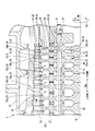
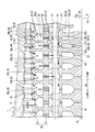
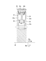
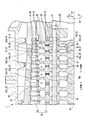
- FIG. 1 It is a principal part notch side view of a gas turbine in one embodiment concerning the present invention. It is an important section sectional view of a compressor in a first embodiment concerning the present invention.
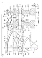
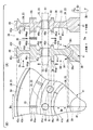
- the rotor disk in 1st embodiment which concerns on this invention is shown, the same figure (A) is sectional drawing of a rotor disk, the same figure (B) is B arrow line view in the same figure (A).
- 15 is a detailed schematic view around a position P3 in FIG. 14; 15 is a detailed schematic view around a position P4 in FIG.
- FIG. 16 is a detailed schematic view around a position P5 in FIG. 15;
- FIG. 17 is a detailed schematic view around a position P6 in FIG. 16;
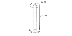
- It is a perspective view of the torque pin of the downstream cavity group in the 1st modification of a second embodiment concerning the present invention.
- 2nd modification of 2nd embodiment which concerns on this invention, Comprising: It is a detailed schematic diagram around position P7 in FIG. 14, or P8.
- the gas turbine includes a compressor 1, a combustor 2, and a turbine 3.
- the compressor 1 compresses external air to generate compressed air.
- the combustor 2 mixes the fuel from the fuel supply source with the compressed air and burns it to generate a combustion gas.
- the turbine 3 is driven by the combustion gas.
- the compressor 1 includes a compressor rotor 20 that rotates around an axis Ar and a cylindrical compressor casing 10 that covers the compressor rotor 20.
- the direction in which the axis Ar extends is referred to as an axial direction Da.
- one side of the axial direction Da is referred to as the upstream side
- the other side of the axial direction is referred to as the downstream side.
- the radial direction based on the axis Ar is simply referred to as the radial direction Dr.
- the side away from the axis Ar in the radial direction Dr is taken as the radially outer side
- the side approaching the axis Ar in the radial direction Dr is taken as the radially inner side.
- An opening is formed on the upstream side of the compressor casing 10. This opening forms an inlet 11i through which the compressor 1 takes in air from the outside.
- the turbine 3 is disposed downstream of the compressor 1.
- the turbine 3 has a turbine rotor 4 that rotates around an axis Ar and a cylindrical turbine casing 5 that covers the turbine rotor 4.
- the compressor rotor 20 and the turbine rotor 4 rotate around the same axis Ar and are connected to each other to form a gas turbine rotor 8.
- the compressor casing 10 and the turbine casing 5 are connected to each other to form a gas turbine casing 9.
- the combustor 2 is fixed to the gas turbine casing 9.
- the compressor of this embodiment is the compressor 1 of the gas turbine described above. Therefore, the compressor 1 of the present embodiment includes the compressor rotor 20 that rotates around the axis Ar, and the cylindrical compressor casing 10 that covers the compressor rotor 20.
- the compressor 1 is an axial flow compressor as shown in FIG.
- the compressor rotor 20 has a rotor shaft 21 and a plurality of moving blade arrays 81.
- the rotor shaft 21 extends in the axial direction Da around the axis Ar.
- the plurality of moving blade arrays 81 are fixed to the outer periphery of the rotor shaft 21 and aligned in the axial direction Da.
- the stationary blade row 11 is fixed at a position downstream of each moving blade row 81.
- One stationary blade row 11 has a plurality of stationary blades 12.
- the plurality of stator blades 12 are arranged in the circumferential direction Dc around the axis Ar to constitute one stator blade row 11.
- one moving blade row 81 has a plurality of moving blades 82.
- the plurality of moving blades 82 are arranged in the circumferential direction Dc around the axis Ar to form one moving blade row 81.
- the vanes 12 are provided inside the radial direction Dr of the wing 13, the outer shroud 14 provided outside the radial direction Dr of the wing 13, and the wing 13 extending in the radial direction Dr. And an inner shroud 15.
- the outer shroud 14 is attached to the inner circumferential side of the compressor casing 10.
- the inner shroud 15 is provided with a seal ring 16 inside the radial direction Dr.
- the moving blade 82 includes a blade 83 extending in the radial direction Dr, a platform 84 provided in the radial direction Dr of the blade 83, and a blade root 85 provided in the radial direction Dr of the platform 84. Have.
- the blade roots 85 are embedded in the rotor shaft 21.
- the air compression flow path 19 through which the air in the compression process passes in the compressor 1 has an annular shape around the axis Ar.
- the outer peripheral side of the air compression flow passage 19 is defined by the compressor casing 10 and the outer shroud 14 of the vane 12. Further, the inner peripheral side of the air compression flow passage 19 is defined by the platform 84 of the moving blade 82 and the inner shroud 15 of the stationary blade 12. The air flows from the upstream side to the downstream side while being compressed in the air compression flow path 19 by the rotation of the compressor rotor 20.
- a plurality of rotor shafts 21 are provided at each position in the axial direction Da between the plurality of moving blade rows 81, in other words, at each position in the axial direction Da of the plurality of stator blade rows 11.
- Cavity 23 is formed.
- the plurality of cavities 23 form an annular shape about the axis Ar and are separated from each other in the radial direction Dr.
- the plurality of cavities 23 formed at positions in the axial direction Da between two adjacent moving blade cascades 81 in the axial direction Da constitute one cavity group 22.
- a plurality of cavity groups 22 are formed in the rotor shaft 21 in the axial direction Da.
- One cavity group 22 is composed of three cavities of an outer cavity 24, an intermediate cavity 25 and an inner cavity 26.
- the outer cavity 24 is formed on the most radially outward side in the rotor shaft 21 among the plurality of cavities.
- the intermediate cavity 25 is formed radially inward of the outer cavity 24 in the radial direction Dr.
- the inner cavity 26 is formed at the innermost radial direction Dr in the rotor shaft 21 among the plurality of cavities.
- the rotor shaft 21 further includes a radially outer flow passage 34 communicating the outer cavity 24 and the air compression flow passage 19, and a plurality of radial intermediate flow passages 35 communicating the outer cavity 24 and the intermediate cavity 25. Is formed.
- the radially outer flow passage 34 is a flow passage that annularly spreads around the axis Ar.
- the plurality of radial intermediate flow paths 35 are separated from each other in the circumferential direction Dc.
- the rotor shaft 21 has a plurality of rotor disks 41, spindle bolts 51, and torque pins 55.
- the plurality of rotor disks 41 are stacked on one another in the axial direction Da.
- the spindle bolt 51 penetrates the plurality of rotor disks 41 and the plurality of intermediate cavities 25 in the axial direction Da.
- the torque pin 55 regulates the relative rotation of the adjacent rotor disks 41.
- One rotor blade row 81 is attached to one rotor disk 41.
- the rotor disk 41 is present for each of the plurality of moving blade arrays 81.
- each of the radially intermediate flow passages 35 communicating the outer cavity 24 and the intermediate cavity 25 is formed between two adjacent rotor disks 41 in the axial direction Da.
- the same figure (A) is a sectional view of the rotor disk 41, and the same figure (B) is a view on arrow B in the same figure (A).
- an upstream first recess 43u On the upstream side of one rotor disk 41, an upstream first recess 43u, an upstream second recess 45u, and an upstream third recess 47u are formed.
- the upstream first recess 43 u is recessed toward the downstream side to form the upstream outer cavity 24 of the rotor disk 41.
- the upstream second recess 45 u is recessed toward the downstream side to form an intermediate cavity 25 on the upstream side of the rotor disk 41.
- the upstream third recess 47 u is recessed toward the downstream side to form the inner cavity 26 on the upstream side of the rotor disk 41.
- annular upstream first arm portion 42u which protrudes toward the upstream side of the axial direction Da relative to the bottom surface of the upstream first recess 43u on the outside in the radial direction Dr of the upstream first recess 43u Is formed. Further, between the upstream first recess 43 u and the upstream second recess 45 u, the axial direction Da is relatively upstream with respect to the bottom surface of the upstream first recess 43 u and the bottom surface of the upstream second recess 45 u.
- An annular upstream second arm portion 44u is formed to project toward the Also, between the upstream second recess 45 u and the upstream third recess 47 u, the axial direction Da is relatively upstream with respect to the bottom surface of the upstream second recess 45 u and the bottom surface of the upstream third recess 47 u.
- An annular upstream third arm 46 u is formed to project toward the
- the annular upstream second arm portion 44 u is formed with a plurality of upstream pin grooves 44 up which are recessed toward the downstream side to connect the upstream first concave portion 43 u and the upstream second concave portion 45 u.
- a downstream first recess 43d is recessed toward the upstream side to form the downstream outer cavity 24 of the rotor disk 41.
- the downstream second recess 45 d is recessed toward the upstream side to form an intermediate cavity 25 on the downstream side of the rotor disk 41.
- the downstream third recess 47 d is recessed toward the upstream side to form the inner cavity 26 on the downstream side of the rotor disk 41.
- annular downstream first arm portion 42d that protrudes toward the downstream in the axial direction Da relative to the bottom surface of the downstream first recessed portion 43d. Is formed. Also, between the downstream first recess 43 d and the downstream second recess 45 d, the axial direction Da is relatively downstream with respect to the bottom surface of the downstream first recess 43 d and the bottom surface of the downstream second recess 45 d.
- An annular downstream second arm portion 44d is formed to project toward the Further, between the downstream second recess 45 d and the downstream third recess 47 d, the axial direction Da is relatively downstream with respect to the bottom surface of the downstream second recess 45 d and the bottom surface of the downstream third recess 47 d.
- An annular downstream third arm portion 46d is formed to project toward the
- the annular downstream second arm portion 44 d is formed with a plurality of downstream pin grooves 44 dp which are recessed toward the upstream side to communicate the downstream first concave portion 43 d and the downstream second concave portion 45 d.
- the outer cavity 24 is defined by the downstream first recess 43 d in the upstream rotor disk 41 of the two rotor disks 41 adjacent in the axial direction Da and the upstream first recess 43 u in the downstream rotor disk 41. Be done.
- the intermediate cavity 25 is defined by the downstream second recess 45 d in the upstream rotor disk 41 of the two rotor disks 41 adjacent in the axial direction Da and the upstream second recess in the downstream rotor disk 41. Be done.
- the inner cavity 26 is defined by the downstream third recess 47 d in the upstream rotor disk 41 of the two rotor disks 41 adjacent in the axial direction Da and the upstream third recess 47 u in the downstream rotor disk 41. Be done.
- the downstream first arm portion 42d of the upstream rotor disk 41 of the two rotor disks 41 adjacent in the axial direction Da and the upstream first arm portion 42u of the downstream rotor disk 41 are in the axial direction with each other. Opposite and separated by Da.
- the radially outer flow passage 34 includes the downstream first arm portion 42 d of the upstream rotor disk 41 and the upstream first arm of the downstream rotor disk 41 of the two rotor disks 41 adjacent in the axial direction Da. It is defined by the part 42u.
- the plurality of downstream pin grooves 44dp in the upstream rotor disk 41 of the two rotor disks 41 adjacent in the axial direction Da and the plurality of upstream pin grooves 44up in the downstream rotor disk 41 are the axial direction Da Are facing each other.
- the pin hole in which the torque pin 55 is mounted is defined by the downstream pin groove 44dp and the upstream pin groove 44up.
- the pin hole in which the torque pin 55 is mounted has a cylindrical shape corresponding to the shape of the cylindrical torque pin 55.
- the rotor disk 41 is formed with a bolt through hole 48 through which the spindle bolt 51 is inserted, penetrating from the bottom surface of the upstream second recess 45 u to the bottom surface of the downstream second recess 45 d. Further, a blade root 85 (see FIG. 4) of the moving blade 82 is mounted between the upstream first arm portion 42 u and the downstream second arm portion 44 d on the outer side of the rotor disk 41 in the radial direction Dr. A moving blade mounting portion 49 is formed.
- a through hole 56 is formed so as to penetrate from one end surface of the cylinder to the other end surface.
- the through hole 56 forms a radial intermediate flow passage 35.
- the first cavity group 22 on the most downstream side of the rotor shaft 21 and the second cavity group 22 on the upstream side adjacent to the first cavity group 22 in the axial direction Da form one set.
- the first cavity group 22 constitutes the downstream cavity group 22d
- the second cavity group 22 constitutes the upstream cavity group 22u.
- the upstream third cavity group 22 adjacent to the second cavity group 22 in the axial direction Da and the upstream fourth cavity group 22 adjacent to the third cavity group 22 in the axial direction Da form one set.
- the third cavity group 22 constitutes the downstream cavity group 22d
- the fourth cavity group 22 constitutes the upstream cavity group 22u.
- the upstream fifth cavity group 22 adjacent to the fourth cavity group 22 in the axial direction Da and the upstream sixth cavity group 22 adjacent to the fifth cavity group 22 in the axial direction Da form one set.
- the fifth cavity group 22 constitutes the downstream cavity group 22d
- the sixth cavity group 22 constitutes the upstream cavity group 22u.
- the radially outer flow passage 34 communicating the outer cavity 24 of the downstream side cavity group 22 d with the air compression flow passage 19 constitutes an inlet flow passage 34 d allowing the air in the air compression flow passage 19 to flow into the outer cavity 24. Further, the radially outer flow passage 34 for communicating the outer cavity 24 of the upstream side cavity group 22 u with the air compression flow passage 19 has an outlet flow passage 34 u for letting the air in the outer cavity 24 flow out into the air compression flow passage 19. I will.
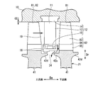
- the bolt through holes 48 of the rotor disk 41 form a gap 48s extending in the axial direction Da with the surface on the inner side in the radial direction Dr of the spindle bolt 51 inserted therein, as shown in FIG.
- the gap 48 s forms an axial flow passage 37.
- the opening for the intermediate cavity 25 of the downstream cavity group 22 d in the axial flow passage 37 constitutes an inlet opening 37 i.
- the opening for the intermediate cavity 25 of the upstream side cavity group 22 u in the axial flow passage 37 constitutes an outlet opening 37 o.
- the radial direction Dr outer edge of the inlet opening 37i in the axial flow passage 37 is located radially inward of the central position in the radial direction Dr of the intermediate cavity 25 of the downstream side cavity group 22d.
- the radial direction Dr outer edge of the outlet opening 37o in the axial flow passage 37 is also positioned radially inward of the central position in the radial direction Dr of the intermediate cavity 25 of the upstream side cavity group 22u.
- the middle position of the intermediate cavity 25 in the radial direction Dr means the height of the radial direction Dr from the radially inner inner circumferential surface to the radially outer inner circumferential surface of the inner circumferential surfaces defining the annular intermediate cavity 25. Indicates a half position of.
- the axial flow path 37 is provided that causes the intermediate cavity 25 of the downstream side cavity group 22 d to communicate with the intermediate cavity 25 of the upstream side cavity group 22 u. Therefore, in the present embodiment, both the intermediate cavity 25 of the downstream side cavity group 22d and the intermediate cavity 25 of the upstream side cavity group 22u form an axial communication cavity.
- a plurality of bolt through holes 48 through which the spindle bolts 51 are inserted are formed in line in the circumferential direction Dc around the axis Ar. Accordingly, a plurality of axial flow paths 37 are also formed in the circumferential direction Dc around the axis Ar in the rotor disk 41.
- the pressure in the air compression flow path 19 is higher on the downstream side.
- the pressure in the radially outer flow passage 34 of the downstream side cavity group 22 d in communication with the downstream air compression flow passage 19 with reference to one moving blade row 81 is based on the one moving blade row 81
- the air flowing into the inlet channel 34d flows into the outer cavity 24 of the downstream side cavity group 22d.
- the air flows into the intermediate cavity 25 through the radial intermediate flow passage 35 formed in the torque pin 55.
- the air that has flowed into the intermediate cavity 25 flows into the intermediate cavity 25 of the upstream cavity group 22 u via the axial flow path 37 formed by the gap 48 s between the bolt through hole 48 of the rotor disk 41 and the spindle bolt 51. Do.
- This air flows into the outer cavity 24 of the upstream cavity group 22 u through the radial intermediate flow passage 35 formed in the torque pin 55.
- the air that has flowed into the outer cavity 24 flows out from the radially outer flow passage 34 that brings the outer cavity 24 of the upstream cavity group 22 u into communication with the air compression flow passage 19 into the air compression flow passage 19. Therefore, as described above, the radially outer flow passage 34 functions as the outlet flow passage 34 u.
- part of the air in the air compression flow channel 19 is from here on the downstream side cavity group 22d and the upstream side cavity group 22u.
- This circulating flow promotes ventilation in each cavity in the rotor shaft 21.
- the compressor rotor 20 in particular, the rotor shaft 21, the dimension in the radial direction Dr is larger than the thickness dimension in the radial direction Dr of the compressor casing 10. For this reason, the compressor rotor 20 has a large heat capacity with respect to the compressor casing 10, and has a thermal responsiveness to a temperature change of the air flowing through the air compression flow passage 19 lower than that of the compressor casing 10. Therefore, when the temperature of the air flowing through the air compression flow path 19 changes, the tip clearance CC changes due to the difference in thermal responsiveness between the compressor rotor 20 and the compressor casing 10.
- the steady-state clearance is the tip clearance CC when the stable operation of the gas turbine continues and both the compressor rotor 20 and the compressor casing 10 continue to have the same temperature. If this steady-state clearance is large, the amount of air passing between the radially outer end of the moving blade 82 and the inner circumferential surface of the compressor casing 10 will increase during steady-state operation of the gas turbine. For this reason, when the steady-state clearance is large, not only the compressor performance at the time of steady-state operation of the gas turbine is lowered, but also the gas turbine performance is lowered.
- the change in tip clearance CC is reduced.
- the steady state clearance can be reduced. Therefore, in the present embodiment, the compressor performance at the time of steady operation of the gas turbine can be enhanced, and as a result, the gas turbine performance can be enhanced.
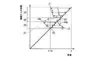
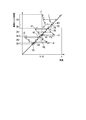
- the horizontal axis represents the circumferential velocity of air
- the vertical axis represents the distance from the axis Ar in the radial direction Dr.
- a thick broken line indicates the circumferential speed of the rotor shaft 21
- a thin solid line indicates the circumferential speed of the air in the rotor shaft 21.
- FIG. 7 shows a circumferential velocity change of air in the rotor shaft 21 in the present embodiment.
- the peripheral speed of the rotor shaft 21 at the position on the axis Ar is zero.
- the peripheral speed increases in proportion to the distance from the axis Ar. For this reason, the rotor shaft 21 has the maximum circumferential velocity V on its outer peripheral surface.
- the air in the air compression flow path 19 flows into the outer cavity 24 of the downstream side cavity group 22 d through the inlet flow path 34 d as described above with reference to FIG.
- the circumferential velocity v1 of air immediately after flowing into the outer cavity 24 can be 0.5 V, which is approximately half of the circumferential velocity V on the outer peripheral surface of the rotor shaft 21.
- the circumferential velocity v1 of air immediately after flowing into the outer cavity 24 is 0.5 V, this is an example, and the circumferential velocity v1 can be changed by clearance adjustment or the like.
- the air flowing into the outer cavity 24 flows in the outer cavity 24 in the circumferential direction Dc relative to the outer cavity 24 and in the radial direction Dr while flowing in the circumferential direction Dc.
- the circumferential velocity of the air increases in inverse proportion to the distance from the axis Ar according to the law of conservation of angular momentum. For this reason, as air flows in the outer cavity 24 in the radial direction Dr, the circumferential velocity of the air increases. When the air reaches the radial direction Dr inner end of the outer cavity 24, the circumferential velocity of the air becomes v2.
- the circumferential velocity v2 is larger than the circumferential velocity v1 of air immediately after flowing into the outer cavity 24. This air flows into any one of the plurality of radial intermediate flow channels 35 opened here.
- the air that has flowed into the radial intermediate flow passage 35 flows radially inward in the radial intermediate flow passage 35 and flows into the intermediate cavity 25.
- the air flows upstream in the axial flow path 37 and flows into the intermediate cavity 25 of the upstream cavity group 22 u. Since the air in the axial passage 37 rotates integrally with the rotor shaft 21 about the axis Ar, the circumferential velocity of the air in the axial passage 37 is substantially the same as the circumferential velocity V3 of the axial passage 37. become.
- a circumferential velocity difference (a circumferential velocity V3 between the circumferential velocity v3 of the air immediately before reaching the inlet opening 37i (see FIG. 6) of the axial channel 37 and the circumferential velocity V3 of the inlet opening 37i of the axial channel 37 v3-V3).
- the air flows radially outward in the radial intermediate flow passage 35 and flows into the outer cavity 24 of the upstream cavity group 22 u. Since the air in the radial intermediate flow passage 35 rotates integrally with the rotor shaft 21 about the axis Ar, the circumferential velocity of the air in the radial intermediate flow passage 35 is equal to the circumferential velocity V 4 a of the radial intermediate flow passage 35. It will be almost the same as
- the air flows in the outer cavity 24 in the circumferential direction Dc relative to the outer cavity 24 and flows outward in the radial direction Dr.
- the circumferential velocity of the air decreases according to the law of conservation of angular momentum. Therefore, as the air flows in the outer cavity 24 in the radial direction Dr, the circumferential speed difference with respect to the outer cavity 24 increases.
- This air returns to the air compression flow path 19 through the outlet flow path 34 u.
- part of the air in the air compression flow channel 19 is the downstream cavity group from here 22d and an upstream cavity group 22u to generate a circulating flow returning to the air compression flow passage 19. That is, in the present embodiment, part of the air in the air compression flow path 19 is the outer cavity 24 of the downstream cavity group 22 d, the intermediate cavity 25 of the downstream cavity group 22 d, the intermediate cavity 25 of the upstream cavity group 22 u, The air flows in the outer cavity 24 of the upstream cavity group 22 u in the above order and returns to the air compression flow path 19.
- the outer cavity 24 of the downstream cavity group 22d, the intermediate cavity 25 of the downstream cavity group 22d, the intermediate cavity 25 of the upstream cavity group 22u, and the upstream side The circulating flow of the air flowing in the outer cavity 24 of the group of cavities 22 u can ventilate the inside of these cavities.
- each cavity 23 can be ventilated by the air flowing in the air compression flow path 19. And in this embodiment, the heat transfer coefficient in the wall surface of the rotor disc 41 can be raised. Therefore, in the present embodiment, the thermal responsiveness of the compressor rotor 20 to the temperature change of the air flowing through the air compression flow path 19 can be enhanced.
- the plurality of axial channels 37 are communicated with each other at an intermediate position in the axial direction Da of the plurality of axial channels 37 formed in a row in the circumferential direction Dc around the axis Ar.
- a circumferential flow passage may be formed.
- the circumferential flow passage is annularly formed about the axis Ar.
- the air flowing into the inlet opening 37i of the axial flow passage 37 flows in the axial flow passage 37 toward the upstream side of the axial direction Da to reach the circumferential flow passage.
- the fluid flows in the circumferential flow channel in the circumferential direction, and flows from any one of the axial flow channels 37 into the upstream intermediate cavity 25. Even if such a form is adopted, the effect of enhancing the thermal responsiveness of the compressor rotor 20 can be obtained as in the present embodiment.
- the intermediate cavity 25 of the downstream side cavity group 22 d and the intermediate cavity 25 of the upstream side cavity group 22 u in the above embodiment are integrated to form one cavity 23. It is.
- a cavity in which the intermediate cavity 25 of the downstream side cavity group 22 d and the intermediate cavity 25 of the upstream side cavity group 22 u are integrated is referred to as a shared cavity 25 x.
- the air in the air compression flow path 19 is the inlet flow path 34 d in the rotor shaft 21, the outer cavity 24 of the downstream cavity group 22 d, the radial intermediate flow path 35 of the downstream cavity group 22 d, and the shared cavity 25x, the radial direction intermediate flow path 35 of the upstream cavity group 22 u, the outer cavity 24 of the upstream cavity group 22 u, and the outlet flow path 34 u flow in the above order and return to the air compression flow path 19.
- the circumferential velocity change of the air until immediately before the air in the air compression flow path 19 reaches the shared cavity 25x is the same as that of the above embodiment. Therefore, the peripheral speed of the air immediately before reaching the shared cavity 25x, that is, the air at the radial direction Dr inner end of the radial direction intermediate flow path 35 of the downstream side cavity group 22d is substantially the same as the peripheral speed of the rotor shaft 21 at this position. It is.
- the outlet opening of the radial intermediate flow passage 35 of the downstream cavity group 22d is formed in the radial direction Dr outer edge of the downstream side portion, and the upstream cavity in the radial direction Dr outer edge of the upstream side portion An inlet opening of the radial intermediate flow passage 35 of the group 22 u is formed.
- no opening of the flow path is formed at all in the region inside the radial direction Dr of the shared cavity 25x.
- the circumferential velocity change of the air that has flowed into the radial intermediate flow passage 35 of the upstream-side cavity group 22 u is the same as that of the above-described embodiment.
- the position of the outlet opening 37o is formed at the above-mentioned position. That is, in the above embodiment, as shown in FIG. 6, the radial direction Dr outer edge of the inlet opening 37i in the axial flow passage 37 is larger in diameter than the central position in the radial direction Dr of the intermediate cavity 25 of the downstream side cavity group 22d.
- the radial direction Dr outer edge of the outlet opening 37o in the axial flow passage 37 is also positioned in the radial direction Dr than the central position in the radial direction Dr of the intermediate cavity 25 of the upstream cavity group 22u. I am doing it.
- the intermediate cavity 25 of the downstream side cavity group 22 d and the intermediate cavity 25 of the upstream side cavity group 22 u are communicated with each other by the axial flow passage 37.
- the inner cavity 26 of the downstream cavity group 22 d and the inner cavity 26 of the upstream cavity group 22 u are communicated with each other by the axial flow passage 39.
- the inner cavity 26 of the downstream side cavity group 22 d and the inner cavity 26 of the upstream side cavity group 22 u form an axial communication cavity.
- a plurality of radially inner flow passages 38 are formed.
- the radially outer flow passage 34 communicates the outer cavity 24 with the air compression flow passage 19.
- the plurality of radially intermediate flow passages 35 communicate the outer cavity 24 with the intermediate cavity 25.
- the plurality of radially inner flow passages 38 communicate the intermediate cavity 25 with the inner cavity 26.
- the plurality of radial intermediate flow channels 35 in the present embodiment are separated from each other in the circumferential direction Dc, similarly to the plurality of radial intermediate flow channels 35 in the first embodiment.
- the plurality of radially inner flow passages 38 in the present embodiment are also separated from each other in the circumferential direction Dc, similarly to the plurality of radially intermediate flow passages 35 in the first embodiment.
- the radially intermediate flow passage 35 communicating with the inner cavity 26 and the radially inner flow passage 38 communicating the intermediate cavity 25 of the cavity group 22 with the inner cavity 26 are all in the axial direction Da.
- the same figure (A) is a sectional view of the rotor disk 41, and the same figure (B) is a view on arrow B in the same figure (A).
- the upstream first arm portion 42u, the upstream first recess 43u, the upstream second arm 44u, the upstream second recess 45u, and the upstream A side third arm portion 46u and an upstream side third concave portion 47u are formed on the upstream side of one rotor disk 41.
- the annular upstream second arm portion 44 u is recessed toward the downstream side to allow the upstream first recess 43 u and the upstream second recess 45 u to communicate with each other.
- the groove 44up is formed.
- a plurality of upstream channel grooves 46up are formed which are recessed toward the downstream side to connect the upstream second recess 45u and the upstream third recess 47u. ing.
- downstream first arm portion 42d On the downstream side of one rotor disk 41, the downstream first arm portion 42d, the downstream first recess 43d, the downstream second arm 44d, the downstream second recess 45d, and the downstream third arm 46d
- the downstream third recess 47d is formed.
- a plurality of downstream pins are recessed toward the upstream side to connect the downstream first recess 43d and the downstream second recess 45d.
- a groove 44dp is formed.
- annular downstream third arm portion 46d there are formed a plurality of downstream channel grooves 46dp which are recessed toward the upstream side to communicate the downstream second concave portion 45d with the downstream third concave portion 47d. ing.
- the outer cavity 24 includes the downstream first recess 43 d in the upstream rotor disk 41 of the two rotor disks 41 adjacent in the axial direction Da, and the downstream cavity It is defined by the upstream first recess 43 u in the rotor disk 41.
- the intermediate cavity 25 is defined by the downstream second recess 45 d in the upstream rotor disk 41 of the two rotor disks 41 adjacent in the axial direction Da and the upstream second recess 45 u in the downstream rotor disk 41. Be done.
- the inner cavity 26 is defined by the downstream third recess 47 d in the upstream rotor disk 41 of the two rotor disks 41 adjacent in the axial direction Da and the upstream third recess 47 u in the downstream rotor disk 41. Be done.
- the radially outer flow passage 34 includes the downstream first arm portion 42 d of the upstream rotor disk 41 of the two rotor disks 41 adjacent in the axial direction Da and the upstream first blade portion 42 d of the downstream rotor disk 41. It is defined by one arm part 42u.
- the pin hole in which the torque pin 55 is mounted is defined by the downstream pin groove 44dp and the upstream pin groove 44up.
- the torque pin 55 is formed with a through hole 56 that forms a radial intermediate flow passage 35.
- the radially outer flow passage 34 communicating the outer cavity 24 of the downstream side cavity group 22 d with the air compression flow passage 19 in the cavity group 22 forming a pair by the rotor shaft 21 is configured to outside the air in the air compression flow passage 19.
- An inlet channel 34d which flows into the cavity 24 is formed.
- the radially outer flow passage 34 for communicating the outer cavity 24 of the upstream side cavity group 22 u with the air compression flow passage 19 has an outlet flow passage 34 u for letting the air in the outer cavity 24 flow out into the air compression flow passage 19. I will.
- the above-mentioned axial flow path which causes the inner cavity 26 of the downstream side cavity group 22d and the inner cavity 26 of the upstream side cavity group 22u to communicate 39 are formed. Therefore, in the rotor disk 41 between the downstream cavity group 22d and the upstream cavity group 22u, as in the first embodiment, the intermediate cavity 25 of the downstream cavity group 22d and the intermediate cavity of the upstream cavity group 22u.
- the axial flow passage 37 communicating with 25 is not formed.
- the opening for the inner cavity 26 of the downstream cavity group 22 d in the axial flow passage 39 constitutes an inlet opening 39 i.
- the radial direction Dr outer edge of the inlet opening 39i in the axial flow passage 39 is located radially inward of the central position in the radial direction Dr of the inner cavity 26 of the downstream side cavity group 22d.
- the opening for the inner cavity 26 of the upstream cavity group 22 u in the axial flow passage 39 constitutes an outlet opening 39 o.
- the radial direction Dr outer edge of the outlet opening 39o in the axial flow passage 39 is also located radially inward of the central position in the radial direction Dr of the inner cavity 26 of the upstream side cavity group 22u.
- the central position of the inner cavity 26 in the radial direction Dr means the height of the radial direction Dr from the radially inner inner circumferential surface to the radially outer inner circumferential surface of the inner circumferential surfaces defining the annular inner cavity 26. Indicates a half position of.
- the radially outer flow passage 34 that causes the outer cavity 24 of the downstream cavity group 22 d to communicate with the air compression flow passage 19 functions as the inlet flow passage 34 d. Air in the air compression flow path 19 flows in.
- the air in the air compression flow passage 19 is the middle in the radial direction of the inlet flow passage 34d in the rotor shaft 21, the outer cavity 24 of the downstream cavity group 22d, and the downstream cavity group 22d. It flows through the flow path 35 and the intermediate cavity 25 of the downstream side cavity group 22d in the above order. Thereafter, the air that has flowed into the intermediate cavity 25 of the downstream cavity group 22 d flows through the radially inner flow passage 38 of the downstream cavity group 22 d and the inner cavity 26 of the downstream cavity group 22 d in the above order. The air that has flowed into the inner cavity 26 of the downstream cavity group 22 d flows into the inner cavity 26 of the upstream cavity group 22 u via the axial flow path 39.
- the air flowing into the inner cavity 26 of the upstream cavity group 22 u passes through the radially inner flow path 38 of the upstream cavity group 22 u and flows into the intermediate cavity 25 of the upstream cavity group 22 u.
- the air that has flowed into the intermediate cavity 25 of the upstream cavity group 22 u passes through the radial intermediate passage 35 of the upstream cavity group 22 u, the outer cavity 24 of the upstream cavity group 22 u, and the outlet passage 34 u as in the above embodiment. It flows in the above order and returns to the air compression flow path 19.
- the circumferential velocity change of the air in the air compression flow path 19 until the air in the air compression flow path 19 reaches the intermediate cavity 25 of the downstream side cavity group 22d is the same as that in the above embodiment.
- air flows into the intermediate cavity 25 of the downstream side cavity group 22d it flows in the intermediate cavity 25 in the circumferential direction Dc relative to the intermediate cavity 25 and flows outward in the radial direction Dr.
- the circumferential velocity of the air increases according to the law of conservation of angular momentum. Therefore, as air flows in the intermediate cavity 25 in the radial direction Dr, the circumferential speed difference with respect to the intermediate cavity 25 increases.
- the air When the air reaches the radial direction Dr inner edge of the intermediate cavity 25, the air flows into any one of the plurality of radially inner flow passages 38 opened here.
- the air flows radially inward in the radially inner flow passage 38 and flows into the inner cavity 26 of the downstream cavity group 22 d. Since the air in the radially inner flow passage 38 rotates integrally with the rotor shaft 21 about the axis Ar, the circumferential velocity of the air in the radially inner flow passage 38 is equal to the circumferential velocity of the radial intermediate flow passage 35 It will be almost the same.
- the air flows radially outward in the radially inner flow passage 38 and flows into the intermediate cavity 25 of the upstream cavity group 22 u. Since the air in the radially inner flow passage 38 rotates integrally with the rotor shaft 21 about the axis Ar, the circumferential velocity of the air in the radially inner flow passage 38 corresponds to the circumferential velocity of the radially inner flow passage 38 It will be almost the same.
- part of the air in the air compression flow channel 19 is downstream from here A circulating flow is generated which returns to the air compression flow path 19 through the cavity group 22d and the upstream cavity group 22u.
- part of the air in the air compression flow path 19 is the outer cavity 24 of the downstream cavity group 22 d, the intermediate cavity 25 of the downstream cavity group 22 d, and the inner cavity 26 of the downstream cavity group 22 d
- the inner cavity 26 of the upstream cavity group 22 u, the intermediate cavity 25 of the upstream cavity group 22 u, and the outer cavity 24 of the upstream cavity group 22 u flow in the above order and return into the air compression channel 19.
- the circulation flow of the air flowing in each cavity of the downstream cavity group 22d and in each cavity of the upstream cavity group 22u It can be ventilated.
- the thermal responsiveness of the compressor rotor 20 to the temperature change of the air flowing through the air compression flow passage 19 can be enhanced more than the first embodiment.
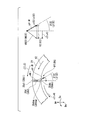
- the inlet side portion including the inlet opening in the flow passage is, as it approaches the inlet opening, the relative direction of the flow of air in the circumferential direction Dc flowing into the inlet opening relative to the inlet opening and It is formed to go to the opposite side.
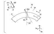
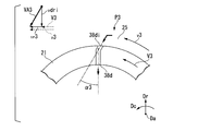
- FIGS. 14 and 16 are schematic views around the position P2 of the inlet opening 35di of the radial intermediate flow passage 35d in FIG.
- the circumferential velocity v1 of the air immediately after flowing from the air compression flow passage 19 through the inlet flow passage 34d into the outer cavity 24 of the downstream side cavity group 22d is the velocity on the outer peripheral surface of the rotor shaft 21. It can be 0.5 V which is approximately half of the circumferential velocity V.
- the air flows in the radial direction Dr while flowing in the circumferential direction Dc relative to the outer cavity 24 in the outer cavity 24.
- the circumferential velocity of the air increases as the air flows in the outer cavity 24 in the radial direction Dr according to the law of conservation of angular momentum.
- the circumferential speed of the air approaches the circumferential speed of the inlet opening 35di of the radial intermediate flow passage 35d.
- the circumferential velocity v2 of this air is the circumferential velocity of the inlet opening 35di of the radial intermediate flow passage 35d. It is slower than V2.
- the inlet side portion including the inlet opening 35di in order to allow air flowing to the opposite side in the circumferential direction Dc relative to the inlet opening 35di to be received by the inlet opening 35di, As the inlet side opening is approached, it is formed to turn to the rotation side in the circumferential direction Dc. That is, the inlet portion of the radial intermediate flow passage 35d is inclined at the inclination angle ⁇ 2 to the rotation side (rotation direction side) with respect to the remaining portion.
- the relative velocity of air near the inlet opening 35di in the outer cavity 24 is VA2
- the relative velocity of the radial component Dc of the radial component is vdri
- tan -1 ⁇ 2 vr2 / It is preferable to set it as vdri.
- the inclination angle ⁇ 2 coincides with the direction of the vector of the relative flow velocity VA2. If such an inclination angle ⁇ 2 is selected, the pressure loss in the process of the air flowing from the outer cavity 24 into the radial intermediate flow passage 35d can be made smaller than by simply inclining the inlet side portion.
- the radial intermediate flow passage 35d is formed in the torque pin 55d. Therefore, as shown in FIG. 21, in the through hole 56d of the torque pin 55d forming the radial intermediate flow passage 35d, the inlet side portion including the inlet opening 35di which is an opening on the outer side of the radial direction Dr approaches the inlet opening 35di. Along the circumferential direction Dc.
- the inlet which is an opening on the outside in the radial direction Dr in the radially inner flow passage 38d that brings the intermediate cavity 25 of the downstream side cavity group 22d into communication with the inner cavity 26.
- the inlet side portion including the opening 38di is formed to face the counter-rotation side in the circumferential direction Dc as the inlet opening 38di is approached.
- the inlet side portion including the inlet opening 39i which is an opening to the inner cavity 26 of the downstream side cavity group 22d in the axial flow passage 39 approaches the inlet opening 39i, In the circumferential direction Dc, it is formed so as to turn to the opposite rotation side.
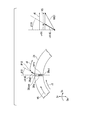
- FIG. 17 is a detailed schematic view around the position P3 of the inlet opening 38di of the radially inner flow passage 38d in FIG.
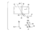
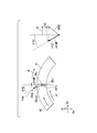
- FIG. 18 is a detailed schematic view around the position P4 of the inlet opening 39i of the axial passage 39 in FIG.
- this inlet opening 38di in order to allow air flowing on the rotational side in the circumferential direction Dc relative to the inlet opening 38di of the radially inner flow passage 38d to be received by the inlet opening 38di, this inlet opening 38di
- the inlet side portion including the is formed so as to face the counter-rotation side in the circumferential direction Dc as it approaches the inlet opening 38di. That is, the inlet portion of the radially inner flow passage 38d is inclined at the inclination angle ⁇ 3 to the opposite rotation side (the opposite rotation direction) with respect to the remaining portion.
- tan -1 ⁇ 3 vr3 / It is preferable to set it as vdri.
- the inclination angle ⁇ 3 coincides with the direction of the vector of the relative flow velocity VA3. If such an inclination angle ⁇ 3 is selected, pressure loss in the process of air flowing from the intermediate cavity 25 into the radially inner flow passage 38d can be made smaller than simply inclining the inlet side portion.
- the inlet side portion including the is formed so as to face the counter-rotation side in the circumferential direction Dc as it approaches the inlet opening 39i. That is, the inlet portion of the axial flow passage 39 is inclined at the inclination angle ⁇ 4 to the opposite rotation side (anti-rotation direction side) with respect to the remaining portion.
- tan -1 ⁇ 4 vr4 / It is preferable to set it as vda.
- the inclination angle ⁇ 4 coincides with the direction of the vector of the relative flow velocity VA4. If such an inclination angle ⁇ 4 is selected, the pressure loss in the process of the air flowing into the axial flow path 39 from the inner cavity 26 can be made smaller than by simply inclining the inlet side portion.
- the inlet which is the opening in the radial direction Dr inner side in the radially inner flow passage 38 u communicating the inner cavity 26 of the upstream cavity group 22 u and the intermediate cavity 25.
- the inlet side portion including the opening 38ui is formed to face the rotation side in the circumferential direction Dc as the inlet opening 38ui is approached.
- an inlet including an inlet opening 35ui which is an opening in the radial direction Dr in the radial intermediate flow passage 35u that brings the intermediate cavity 25 of the upstream cavity group 22u into communication with the outer cavity 24.
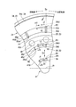
- FIG. 15 is a fragmentary arrow view of a rotor disk 41 of the present modified example in which the XV arrow view in FIG. 11 is modified. That is, FIG. 15 is a view of the rotor disk 41 of the present modification viewed from the upstream side to the downstream side of the axial direction Da. Therefore, the rotation side in the circumferential direction Dc depicted in FIG. 15 is opposite to the rotation side in the circumferential direction Dc depicted in FIG. 14.
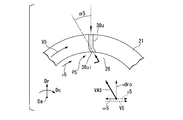
- FIG. 19 is a detailed schematic view around the position P5 of the inlet opening 38ui of the radially inner flow passage 38u in FIG.
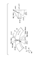
- FIG. 20 is a detailed schematic diagram around the position P6 of the inlet opening 35ui of the radial intermediate flow passage 35u in FIG.
- the direction is the anti-rotation side in the circumferential direction Dc.
- the inlet side portion including the opening 38ui is formed to face the rotational side in the circumferential direction Dc as the inlet opening 38ui is approached. That is, the inlet portion of the radially inner flow passage 38u is inclined to the rotation portion (rotation direction side) with respect to the remaining portion by the inclination angle ⁇ 5.
- the inclination angle ⁇ 5 coincides with the direction of the vector of the relative flow velocity VA5. If such an inclination angle ⁇ 5 is selected, the pressure loss in the process of air flowing from the inner cavity 26 into the radially inner flow passage 38u can be made smaller than by simply inclining the inlet side portion.
- the inlet-side portion including 35 ui is formed to face the rotational side in the circumferential direction Dc as it approaches the inlet opening 35 ui. That is, the inlet portion of the radial intermediate flow passage 35u is inclined to the rotation portion (rotation direction side) with respect to the remaining portion by the inclination angle ⁇ 6.
- the inclination angle ⁇ 6 coincides with the direction of the vector of the relative flow velocity VA6. If such an inclination angle ⁇ 6 is selected, the pressure loss in the process of air flowing from the intermediate cavity 25 into the radial intermediate flow passage 35u can be made smaller than by simply inclining the inlet side portion.
- the radial intermediate flow passage 35u is formed in the torque pin 55u. Therefore, as shown in FIG. 22, in the through hole 56u of the torque pin 55u forming the radial intermediate flow passage 35u, the inlet side portion including the inlet opening 35ui which is an opening on the inner side in the radial direction Dr approaches the inlet opening 35ui Along the circumferential direction Dc.
- This modification is an example in which the outlet portion of the radial flow passage or the axial flow passage is inclined toward the rotation direction side of the rotor shaft 21 or to the opposite rotation side opposite to the rotation direction side. .
- the radial flow path of the downstream cavity group 22d and the radial flow path of the upstream cavity group 22u and the outlet portion of each flow path of the axial flow path shown in the first modification described above are inclined with respect to the rotation direction It is an example which does not open in the direction which corresponds to radial direction Dr or axial direction Da.
- these outlet portions may be inclined in the rotational direction or in the opposite side (anti-rotational side) with respect to the rotational direction.
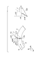
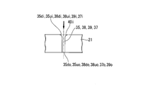
- FIG. 23 shows an example in which the outlet side portion 35 dop including the radially inner outlet opening 35 do of the radial direction intermediate flow path 35 d of the downstream side cavity group 22 d is inclined in the rotational direction.
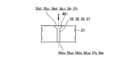
- FIG. 24 shows an example in which the outlet side portion 35dop including the outlet opening 35do of the radial intermediate flow passage 35d is inclined to the opposite side to the opposite side with respect to the rotational direction side. 23 and 24 are detailed schematic views around the position P7 of the outlet opening 35do of the radial intermediate flow passage 35d in FIG.
- a velocity component (relative circumferential velocity) vr21 in the circumferential direction Dc of the axial velocity vdriL of the outlet side portion 35dop is added to the circumferential velocity V2 of air. That is, in the outlet-side portion 35dop of the radial intermediate flow passage 35d, the circumferential velocity V3 of air is (V2 + vr21). That is, the air immediately after flowing into the intermediate cavity 25 (axial communication cavity) from the outlet side portion 35 dop flows inward in the radial direction Dr at the peripheral speed V3 which is faster by the relative peripheral speed difference vr21 with the intermediate cavity 25.
- the circumferential velocity of the air increases as the air flows in the intermediate cavity 25 in the radial direction Dr according to the law of conservation of angular momentum. That is, as air flows radially inward in the radial direction Dr, the circumferential speed difference between the intermediate cavity 25 and the pressure increases as the air flows into the radially inner flow passage 38d.
- the heat transfer coefficient between the air and the intermediate cavity 25 is increased to promote heat transfer.
- the circumferential velocity of air decreases by the velocity component (relative circumferential velocity) vr22 of the circumferential direction Dc of the axial velocity vdriM of the outlet side portion 35dop. That is, in the outlet side portion 35dop of the radial intermediate flow passage 35d, the circumferential velocity V3 of the air is (V2-vr22). That is, the air immediately after flowing into the intermediate cavity 25 (axial communication cavity) from the outlet side portion 35 dop has a relative peripheral speed difference vr22 with the intermediate cavity 25 with respect to the peripheral speed V2 of the air in the radial intermediate flow path 35d. It flows toward the inner side of the radial direction Dr at a small circumferential speed.
- the circumferential velocity of air increases as it flows through the intermediate cavity 25 in the radial direction Dr according to the law of conservation of angular momentum.
- the circumferential speed of the intermediate cavity 25 decreases as it goes inward in the radial direction Dr. Therefore, in the process of air flowing in the intermediate cavity 25 in the radial direction Dr, the circumferential speed difference between the air and the intermediate cavity 25 gradually decreases. The circumferential speed difference between the air and the intermediate cavity 25 is reduced, and the heat transfer coefficient with the intermediate cavity 25 is reduced.
- FIG. 23 also shows an example in which the outlet side portion 38dop including the outlet opening 38do of the radially inner flow passage 38d is inclined toward the rotational direction with respect to the remaining portion of the radially inner flow passage 38d at an inclination angle ⁇ 31.
- reference numerals relating to the radially inner flow passage 38 d are indicated in parentheses.
- the portion in () of FIG. 23 is a detailed schematic view around the position P8 of the outlet opening 35 do of the radial intermediate flow passage 35 d in FIG.
- the concept of the circumferential velocity of air flowing into the inner cavity 26 from the radially inner flow passage 38 d is the same as the air flow flowing through the radial intermediate flow passage 35 d.
- the circumferential speed difference between the air and the inner cavity 26 is enlarged, and the heat transfer coefficient is enhanced. Is also similar to the air flow flowing into the intermediate cavity 25 from the radial intermediate flow passage 35d.
- FIG. 24 also shows an example in which the outlet side portion 38dop of the radially inner flow passage 38d is inclined toward the rotational direction with respect to the remaining portion of the radially inner flow passage 38d at an inclination angle ⁇ 32.
- a portion in () of FIG. 24 is a detailed schematic view around the position P8 of the outlet opening 35 do of the radial intermediate flow passage 35 d in FIG.
- the concept of the peripheral velocity of the air flowing into the inner cavity 26 from the radially inner flow passage 38d in this case is the same as the air flow flowing through the radial intermediate flow passage 35d.
- the effect of reducing pressure loss due to changes in circumferential velocity when air flows into the axial flow passage 39 is also similar to the air flow flowing into the intermediate cavity 25 from the radial intermediate flow passage 35d.
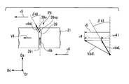
- FIG. 25 shows the outlet side portion 39 op including the outlet opening 39 o on the upstream side (upstream side of the axial direction Da) of the axial flow passage 39 of the downstream side cavity group 22 d with respect to the remaining portion of the axial flow passage 39.
- the example which inclined to the rotation direction side is shown.
- FIG. 26 shows an example in which the outlet side portion 39op of the axial flow passage 39 is inclined to the opposite rotation side to the rotation direction side.
- 25 and 26 are detailed schematic views around the position P9 of the outlet opening 39o of the axial passage 39 in FIG.
- a velocity component (relative circumferential velocity) vr41 in the circumferential direction Dc of the axial velocity vdaL of the outlet side portion 39op is added to the circumferential velocity V4 of air. That is, in the outlet side portion 39 op of the axial flow passage 39, the circumferential velocity V5 of the air is [V4 + vr41]. That is, the air immediately after flowing into the inner cavity 26 from the outlet side portion 39op flows in the inner cavity 26 in the radial direction Dr at the peripheral velocity V5 which is faster by the relative peripheral velocity difference vr41 with the inner cavity 26.
- the circumferential velocity of the air gradually decreases as the air flows from the inner cavity 26 outward in the radial direction Dr according to the law of conservation of angular momentum.
- the circumferential speed of the inner cavity 26 increases as it goes outward in the radial direction Dr. Accordingly, in the process of air flowing outward in the inner cavity 26 in the radial direction Dr, the circumferential speed difference between the air and the inner cavity 26 gradually decreases. As the circumferential velocity difference between the air and the inner cavity 26 decreases, the heat transfer coefficient with the inner cavity 26 decreases.
- the circumferential velocity of the air decreases by the velocity component (relative circumferential velocity) vr42 of the circumferential direction Dc of the axial velocity vdaM of the outlet side portion 35op. That is, in the outlet-side portion 39 op of the axial flow passage 39, the circumferential velocity V5 of air is (V4-vr42). That is, the air immediately after flowing into the inner cavity 26 from the outlet-side portion 39op of the axial passage 39 has a relative circumferential velocity difference vr42 with respect to the inner cavity 26 with respect to the circumferential velocity V4 of the air in the axial passage 39 It flows in the inner cavity 26 radially outward at a small circumferential speed.
- the circumferential velocity of the air decreases as the air flows in the inner cavity 26 and radially outward according to the law of conservation of angular momentum.
- the circumferential speed of the inner cavity 26 increases as it goes outward in the radial direction Dr. That is, as the air flows through the inner cavity 26 in the radial direction Dr, the circumferential speed difference between the air and the inner cavity 26 increases. That is, as the air flows outward in the radial direction Dr, the peripheral speed difference between the air and the inner cavity 26 increases, and the pressure loss when the air flows into the radial inner flow passage 38 u increases. The heat transfer rate with the inner cavity 26 is increased, and heat transfer is promoted.
- FIG. 27 shows an example in which the outlet side portion 38 uop including the outlet opening 38 uo of the radially inner flow passage 38 u in the upstream cavity group 22 u is inclined in the rotational direction with respect to the remaining portion of the radially inner flow passage 38 u .
- FIG. 28 shows an example in which the outlet side portion 38 uop of the radially inner flow passage 38 u is inclined to the opposite rotation side opposite to the rotational direction with respect to the remaining portion of the radially inner flow passage 38 u.
- 27 and 28 are detailed schematic views around the position P10 of the outlet opening 38uo of the radially inner flow passage 38u in FIG.
- a velocity component (relative circumferential velocity) vr51 in the circumferential direction Dc of the axial velocity vdroM of the outlet side portion 38uop is added to the circumferential velocity V5 of air. That is, in the outlet side portion 38 uop of the radially inner flow passage 38 u, the circumferential velocity V 6 of air is (V 5 + vr 51). That is, the air immediately after flowing into the intermediate cavity 25 (axial communication cavity) from the outlet side portion 38 uop flows outward in the radial direction Dr at the peripheral speed V6 which is faster by the relative peripheral speed difference vr51 with the intermediate cavity 25.
- the circumferential velocity of air decreases as the air flows in the intermediate cavity 25 to the outside in the radial direction Dr according to the law of conservation of angular momentum.
- the circumferential speed of the intermediate cavity 25 increases as it goes outward in the radial direction Dr. Accordingly, in the process of air flowing outward in the intermediate cavity 25 in the radial direction Dr, the circumferential speed difference between the air and the intermediate cavity 25 gradually decreases. As the circumferential speed difference between the air and the intermediate cavity 25 decreases, the heat transfer coefficient with the intermediate cavity 25 decreases.
- the circumferential velocity of the air decreases by the velocity component (relative circumferential velocity) vr52 of the circumferential direction Dc of the axial velocity vdroM of the outlet side portion 38 uop. That is, in the outlet side portion 38 uop of the radially inner flow passage 38 u, the circumferential velocity V 6 of air is (V 5 -vr 52).
- the air immediately after flowing into the intermediate cavity 25 from the outlet side portion 38 uop of the radially inner flow passage 38 u has a relative circumferential speed difference with the intermediate cavity 25 with respect to the circumferential velocity V5 of the air in the radially inner flow passage 38 u It flows in the inner cavity 26 toward the radial direction Dr at a peripheral speed V6 which is smaller by vr52.
- the circumferential velocity of air decreases as the air flows in the intermediate cavity 25 to the outside in the radial direction Dr according to the law of conservation of angular momentum.
- the circumferential speed of the intermediate cavity 25 increases as it goes outward in the radial direction Dr.
- the circumferential speed difference between the air and the intermediate cavity 25 increases. That is, as the air flows in the intermediate cavity 25 to the outside in the radial direction Dr, the circumferential velocity difference between the air and the intermediate cavity 25 is expanded, and the pressure when the air flows into the radial intermediate flow passage 35 u Although the loss is increased, the heat transfer coefficient with the intermediate cavity 25 is increased and heat transfer is promoted.
- FIG. 29 shows an example in which the outlet side portion 35uop including the outlet opening 35uo of the radial intermediate flow passage 35u in the upstream cavity group 22u is inclined in the rotational direction with respect to the remaining portion of the radial inner flow passage 38u. .
- FIG. 29 is a detailed schematic view around the position P11 of the outlet opening 35uo of the radial intermediate flow passage 35u in FIG.
- the circumferential velocity of the air decreases by the velocity component (relative circumferential velocity) vr 62 in the circumferential direction Dc of the axial velocity vdroM of the outlet side portion 35 uop. That is, in the outlet-side portion 35uop of the radial intermediate flow passage 35u, the circumferential velocity V7 of air is (V6-vr62).
- the air immediately after flowing into the outer cavity 24 from the outlet side portion 35 uop of the radial intermediate flow passage 35 u has a relative circumferential velocity difference with the outer cavity 24 with respect to the circumferential velocity V6 of the air in the radial intermediate flow passage 35 u It flows in the outer cavity 24 in the radial direction Dr at a peripheral speed V7 which is smaller by vr62.
- the circumferential velocity of the air decreases as the air flows in the outer cavity 24 and radially outward according to the law of conservation of angular momentum.
- the circumferential speed of the outer cavity 24 increases as it goes outward in the radial direction Dr.
- the circumferential speed difference between the air and the outer cavity 24 increases. That is, as air flows in the outer cavity 24 in the radial direction Dr, the circumferential velocity difference between the air and the outer cavity 24 is increased, and the heat transfer coefficient with the outer cavity 24 is increased, and the heat is increased. Transmission is facilitated.
- the upstream cavity group 22 u and the downstream cavity group 22 d have different effects caused by the direction (rotation direction side or anti-rotation direction side) in which the outlet portion of the radial flow passage is inclined with respect to the rotation direction. . That is, when the outlet side portion 35dop of the radially intermediate flow passage 35d of the downstream side cavity group 22d or the outlet side portion 38dop of the radially inner flow passage 38d is inclined in the rotational direction, the air and the intermediate cavity 25 or the inner cavity 26 Circumferential speed difference with the Therefore, in this case, heat transfer can be promoted between the air and the intermediate cavity 25 or the inner cavity 26, and the thermal responsiveness of the intermediate cavity 25 or the inner cavity 26 can be improved.
- outlet side portion 35 uop of the radial intermediate flow passage 35 u of the upstream cavity group 22 u or the outlet side portion 38 u op of the radial inner flow passage 38 u or the outlet side portion 39 op of the axial flow passage 39 is inclined in the opposite direction.
- the circumferential velocity difference between the air and the outer cavity 24 or between the air and the intermediate cavity 25 or between the air and the inner cavity 26 is increased. Therefore, in this case, heat transfer is promoted between the air and the outer cavity 24 or the intermediate cavity 25 or the inner cavity 26 to improve the thermal responsiveness of the outer cavity 24 or the intermediate cavity 25 or the inner cavity 26. be able to.
- the selection of the direction and inclination angle with respect to the rotational direction can be appropriately selected in combination in which the thermal responsiveness is the highest in consideration of the performance and structure of the compressor.
- this modification is a 2nd modification of 2nd embodiment, you may deform
- the first modification and the second modification may be combined as appropriate.
- “Third Modification of Second Embodiment” 30 and 31 show the inlet side portion of the radial flow path (radial intermediate flow paths 35d and 35u, radial inner flow paths 38d and 38u) or axial flow paths 37 and 39 from the inlet opening to the outlet opening
- the inner diameter of the flow passage may be formed to be smaller as it progresses.
- the sloped surface 40i when the inlet shape is in the shape of a bell mouth and viewed in a cross section parallel to the longitudinal direction of these channels, the sloped surface 40i having a curved surface defining the inlet channel. It is. Further, FIG.
- the inlet shape has a funnel shape and the surface defining the inlet shape is formed with a linear inclination when viewed in a cross section parallel to the longitudinal direction of these flow paths .
- this modification is a 3rd modification of 2nd embodiment, you may deform
- the first modification, the second modification and the third modification may be combined as appropriate.
- two cavity groups 22 adjacent in the axial direction Da are combined.
- three or more cavity groups 22 adjacent in the axial direction Da may be a set.
- the most upstream cavity group 22 of the three cavity groups 22 constituting this group is the upstream side.
- the cavity group 22 u may be used, and the remaining two cavity groups 22 may be used as the downstream cavity group 22 d.
- the intermediate cavities (axially communicating cavities) 25 in the downstream first cavity group 22d1 and the upstream second cavity group 22d2 are axially flowed with each other.
- the passage 37 communicates with each other, and the intermediate cavities (axially communicating cavities) 25 in the second downstream cavity group 22 d 2 and the upstream cavity group 22 u communicate with each other in the axial passage 37.
- the most upstream cavity group 22 of the four cavity groups 22 constituting this set is the upstream cavity group, and the remaining The three cavity groups 22 may be used as the downstream cavity group. Further, among the four cavity groups 22 constituting this set, the two upstream cavity groups 22 may be used as the upstream cavity, and the remaining two cavity groups 22 may be used as the downstream cavity group.
- the present invention is applicable to the cavity group 22 from the first cavity group 22 on the most downstream side to the sixth cavity group 22 on the upstream side of the rotor shaft 21.
- the cavity group 22 from the first cavity group 22 on the most downstream side of the rotor shaft 21 to, for example, the eighth cavity group 22 on the upstream side may be the application object of the present invention.
- the entire cavity group 22 on the upstream side from the cavity group 22 may be subjected to the present invention.
- the cavity group 22 from the first cavity group 22 on the most downstream side to the fourth cavity group 22 on the upstream side of the rotor shaft 21 may be an application target of the present invention.
- the cavity group 22 from the first cavity group 22 to the upstream second cavity group 22 may be the application object of the present invention.
- the present invention is applicable to a plurality of cavity groups 22 adjacent to each other in the axial direction Da and including the first cavity group 22 most downstream in the rotor shaft 21.
- the first cavity group 22 is included most downstream in the rotor shaft 21 as an application target of the present invention. This is because the pressure at the position in the axial direction Da where the first cavity group 22 is present in the air compression flow passage 19 is higher than that at other positions, and the temperature at this position in the rotor shaft 21 This is because the change is larger than other positions.
- each of the above each embodiment and each modification is a compressor of a gas turbine, this invention is not limited to this.
- the gas flowing into the compressor is not limited to air.
- the energy to be generated is larger than that in each of the above-described embodiments and modifications. Moreover, since the temperature of the air used for ventilation is higher than the temperature of the portion of the rotor shaft 21 where the stationary blade row 11 is provided, the ventilation effect is smaller than in the above-described embodiments and modifications. Therefore, as described in each of the embodiments and the modifications described above, a portion of the air in the compression process flowing through the air compression flow path 19 of the compressor 1 is guided into the rotor shaft 21 as in the above-described embodiments and modifications. It is preferable to ventilate the inside of each cavity with this air.
- the thermal responsiveness of the rotor shaft to temperature changes of the gas flowing through the gas compression flow path can be further enhanced.
Landscapes
- Engineering & Computer Science (AREA)
- Mechanical Engineering (AREA)
- General Engineering & Computer Science (AREA)
- Chemical & Material Sciences (AREA)
- Combustion & Propulsion (AREA)
- Physics & Mathematics (AREA)
- Thermal Sciences (AREA)
- Structures Of Non-Positive Displacement Pumps (AREA)
- Turbine Rotor Nozzle Sealing (AREA)
Abstract
Description
本願は、2015年4月27日に、日本国に出願された特願2015-090289号に基づき優先権を主張し、この内容をここに援用する。
圧縮機ケーシング内で軸線を中心として回転する圧縮機ロータにおいて、前記軸線を中心として、軸方向に延びているロータ軸と、前記ロータ軸の外周に固定され、前記軸方向に並んでいる複数の動翼列と、を備える。前記ロータ軸には、複数の前記動翼列の相互間の軸方向における各位置に、前記軸線を中心として環状を成し、前記軸線に対する径方向で互いに離間している複数のキャビティで構成されるキャビティ群が形成されている。前記ロータ軸の外周側であって前記軸方向で複数の前記動翼列が存在する気体圧縮流路中を気体が流れてくる圧力の低い側が前記軸方向における上流側を成し、前記上流側の反対側で気体の圧力が高くなる側が前記軸方向における下流側を成す。前記キャビティ群を構成する複数の前記キャビティのうちで、最も径方向外側のキャビティが外側キャビティを成し、前記外側キャビティよりも径方向内側のいずれかのキャビティが軸方向連通キャビティを成す。少なくとも二つの前記キャビティ群のうち、上流側の一以上のキャビティ群が上流側キャビティ群を成し、前記上流側キャビティ群に対して下流側に位置する残りのキャビティ群が下流側キャビティ群を成す。前記ロータ軸には、さらに、前記気体圧縮流路中の気体を、前記下流側キャビティ群の前記外側キャビティに流入させる入口流路と、前記下流側キャビティ群の前記外側キャビティ内に流入した気体が前記下流側キャビティ群の前記軸方向連通キャビティに至るよう、前記径方向を含む方向に延びて、該外側キャビティから該軸方向連通キャビティまでの複数のキャビティで、前記径方向で隣り合う二つのキャビティ相互を連通させる径方向流路と、前記軸方向を含む方向に延びて、前記下流側キャビティ群の前記軸方向連通キャビティと前記上流側キャビティ群の前記軸方向連通キャビティとを連通させる軸方向流路と、前記上流側キャビティ群の前記軸方向連通キャビティ内の気体が前記上流側キャビティ群の前記外側キャビティに至るよう、前記径方向を含む方向に延びて、該軸方向連通キャビティから該外側キャビティまでの複数のキャビティで、前記径方向で隣り合う二つのキャビティ相互を連通させる径方向流路と、前記上流側キャビティ群の前記外側キャビティ内の気体を前記気体圧縮流路中に流出させる出口流路と、が形成されている。前記軸方向流路における前記下流側キャビティ群の前記軸方向連通キャビティに対する開口である入口開口の径方向外側縁は、環状の該軸方向連通キャビティを画定する内周面のうちの径方向外側内周面よりも径方向内側に位置する。前記軸方向流路における前記上流側キャビティ群の前記軸方向連通キャビティに対する開口である出口開口の径方向外側縁は、環状の該軸方向連通キャビティを画定する内周面のうちの径方向外側内周面よりも径方向内側に位置する。
前記第一態様の前記圧縮機ロータにおいて、前記軸方向流路における前記入口開口の径方向外側縁は、前記下流側キャビティ群の前記軸方向連通キャビティの径方向における中央位置よりも径方向内側に位置し、前記軸方向流路における前記出口開口の径方向外側縁は、前記上流側キャビティ群の前記軸方向連通キャビティの径方向における中央位置よりも径方向内側に位置する。
前記第一又は第二態様の前記圧縮機ロータにおいて、前記ロータ軸には、前記軸線に対する周方向で互いに離間している複数の前記軸方向流路が形成されている。
前記第一から第三態様のいずれかの前記圧縮機ロータにおいて、前記上流側キャビティ群の前記径方向流路における径方向内側の開口である入口開口が、前記ロータ軸の回転方向側に傾く前記入口開口を含む前記径方向流路の入口側部分と、前記軸方向流路における前記入口開口が、前記ロータ軸の回転方向側とは反対側に傾く前記入口開口を含む前記軸方向流路の入口側部分と、のうち、少なくともいずれか一つの入口側部分を備える。
前記第一から第四態様のいずれかの前記圧縮機ロータにおいて、前記下流側キャビティ群は、3以上の前記キャビティを有し、前記3以上のキャビティのうち、前記外側キャビティを除く2以上の前記キャビティ相互を連通させる前記径方向流路における径方向外側の開口である入口開口を含む該径方向流路の入口側部分は、前記ロータ軸の回転方向側とは反対側に向かうよう傾いている。
前記第一から第五態様のいずれかの前記圧縮機ロータにおいて、前記下流側キャビティ群の前記径方向流路における径方向内側の開口である出口開口を含む前記径方向流路の出口側部分と、前記上流側キャビティ群の前記径方向流路における径方向外側の開口である出口開口を含む前記径方向流路の出口側部分と、前記軸方向流路における前記出口開口を含む前記軸方向流路の出口側部分と、のうちいずれか一つの出口側部分は、前記ロータ軸の回転方向側又は前記ロータ軸の回転方向側とは反対側に傾いていてもよい。
前記第一から第六態様のいずれかの前記圧縮機ロータにおいて、前記入口開口を含む流路の入口側部分は、前記入口開口から前記流路の前記入口開口とは反対側の出口開口側に向かうに連れて次第に、流路内径が小さくなる。
前記第一から第七態様のいずれかの前記圧縮機ロータにおいて、前記ロータ軸は、前記軸方向で互いに積層されている複数のロータディスクと、前記径方向に延びて、前記軸方向で隣接する前記ロータディスクのそれぞれに係合して、隣接するロータディスク相互の相対回転を規制するトルクピンと、を有し、前記トルクピンは、前記下流側キャビティ群を構成する複数のキャビティのうちで前記径方向で隣り合うキャビティの相互間の位置と、前記上流側キャビティ群を構成する複数のキャビティのうちで前記径方向で隣り合うキャビティの相互間の位置と、に配置され、前記トルクピンには、前記径方向に貫通する貫通孔が形成され、前記貫通孔が前記径方向流路を形成する。
前記第一から第八態様のいずれかの前記圧縮機ロータにおいて、前記ロータ軸は、前記軸方向で互いに積層されている複数のロータディスクと、前記軸方向に延びて、複数の前記ロータディスク、前記下流側キャビティ群の前記軸方向連通キャビティ及び前記上流側キャビティ群の前記軸方向連通キャビティを貫通するスピンドルボルトと、を有し、前記下流側キャビティ群の前記軸方向連通キャビティと前記上流側キャビティ群の前記軸方向連通キャビティとの間に存在するロータディスクに形成され、前記スピンドルボルトが貫通するボルト貫通孔は、前記スピンドルボルトとの間に前記軸方向に延びる隙間を有し、前記ボルト貫通孔の前記隙間は、前記軸方向流路を形成する。
前記第九態様の前記圧縮機ロータにおいて、前記ボルト貫通孔のうちで前記軸方向流路を形成する前記隙間は、前記スピンドルボルトに対する径方向内側に位置する。
前記第一から第十態様のずれかの前記圧縮機ロータにおいて、前記キャビティ群を構成する複数の前記キャビティのうち、最も径方向内側のキャビティが前記軸方向連通キャビティを成す。
前記第一から第十一態様のいずれかの前記圧縮機ロータにおいて、前記軸方向で隣り合う二つの前記キャビティ群のうち、前記上流側のキャビティ群が上流側キャビティ群を成し、前記下流側のキャビティ群が下流側キャビティ群を成す。
前記第一から第十二態様のいずれかの前記圧縮機ロータと、前記圧縮機ケーシングと、を備える。
前記第十三態様の前記圧縮機と、前記圧縮機で圧縮された空気中で燃料を燃焼させて燃焼ガスを生成する燃焼器と、前記燃焼ガスで駆動するタービンと、を備える。
ガスタービンの一実施形態について、図1を参照して説明する。
圧縮機の第一実施形態について、図2~図9を参照して説明する。
圧縮機の第二実施形態について、図10~図13を参照して説明する。
空気は、径方向内側流路38内を径方向Dr外側に向かって流れて、上流側キャビティ群22uの中間キャビティ25に流入する。径方向内側流路38内の空気は、軸線Arを中心としてロータ軸21と一体に回転するため、径方向内側流路38内の空気の周速は、径方向内側流路38の周速とほぼ同じになる。
上記第二実施形態の第一変形例について、図14~図22を参照して説明する。
次に、上記第二実施形態の第二変形例について、図23~図29を参照して説明する。
図30及び図31は、径方向流路(径方向中間流路35d,35u、径方向内側流路38d,38u)又は軸方向流路37,39の入口側部分を、入口開口から出口開口に進むに連れて流路内径が小さくように形成してもよい。具体的に、図30は、入口形状がベルマウス状を成し、これらの流路の長手方向に平行な断面で見た場合、入口流路を画定する面が曲面状に形成された斜面40iである。また、図31は、入口形状が漏斗状を成し、これらの流路の長手方向に平行な断面で見た場合、入口形状を画定する面が直線状の傾きで形成された斜面40iである。このような入口形状であれば、空気が流路に流入する際、空気流の乱れが発生せず、圧力損失の低減ができる。
上記第一実施形態の他の変形例について、図32を参照して説明する。
以上の各実施形態及び各変形例では、いずれも、ロータ軸21で最も下流側の第一キャビティ群22から上流側の第六キャビティ群22までのキャビティ群22を本発明の適用対象にしている。しかしながら、ロータ軸21で最も下流側の第一キャビティ群22から、例えば、上流側の第八キャビティ群22までのキャビティ群22を本発明の適用対象にしてもよいし、最も下流側の第一キャビティ群22から上流側の全キャビティ群22を本発明の適用対象にしてもよい。また、例えば、ロータ軸21で最も下流側の第一キャビティ群22から上流側の第四キャビティ群22までのキャビティ群22を本発明の適用対象にしてもよいし、ロータ軸21で最も下流側の第一キャビティ群22から上流側の第二キャビティ群22までのキャビティ群22を本発明の適用対象にしてもよい。
Claims (14)
- 圧縮機ケーシング内で軸線を中心として回転する圧縮機ロータにおいて、
前記軸線を中心として、軸方向に延びているロータ軸と、
前記ロータ軸の外周に固定され、前記軸方向に並んでいる複数の動翼列と、
を備え、
前記ロータ軸には、複数の前記動翼列の相互間の軸方向における各位置に、前記軸線を中心として環状を成し、前記軸線に対する径方向で互いに離間している複数のキャビティで構成されるキャビティ群が形成され、
前記ロータ軸の外周側であって前記軸方向で複数の前記動翼列が存在する気体圧縮流路中を気体が流れてくる圧力の低い側が前記軸方向における上流側を成し、前記上流側の反対側で気体の圧力が高くなる側が前記軸方向における下流側を成し、
前記キャビティ群を構成する複数の前記キャビティのうちで、最も径方向外側のキャビティが外側キャビティを成し、前記外側キャビティよりも径方向内側のいずれかのキャビティが軸方向連通キャビティを成し、
少なくとも二つの前記キャビティ群のうち、上流側の一以上のキャビティ群が上流側キャビティ群を成し、前記上流側キャビティ群に対して下流側に位置する残りのキャビティ群が下流側キャビティ群を成し、
前記ロータ軸には、さらに、
前記気体圧縮流路中の気体を、前記下流側キャビティ群の前記外側キャビティに流入させる入口流路と、
前記下流側キャビティ群の前記外側キャビティ内に流入した気体が前記下流側キャビティ群の前記軸方向連通キャビティに至るよう、前記径方向を含む方向に延びて、該外側キャビティから該軸方向連通キャビティまでの複数のキャビティで、前記径方向で隣り合う二つのキャビティ相互を連通させる径方向流路と、
前記軸方向を含む方向に延びて、前記下流側キャビティ群の前記軸方向連通キャビティと前記上流側キャビティ群の前記軸方向連通キャビティとを連通させる軸方向流路と、
前記上流側キャビティ群の前記軸方向連通キャビティ内の気体が前記上流側キャビティ群の前記外側キャビティに至るよう、前記径方向を含む方向に延びて、該軸方向連通キャビティから該外側キャビティまでの複数のキャビティで、前記径方向で隣り合う二つのキャビティ相互を連通させる径方向流路と、
前記上流側キャビティ群の前記外側キャビティ内の気体を前記気体圧縮流路中に流出させる出口流路と、
が形成され、
前記軸方向流路における前記下流側キャビティ群の前記軸方向連通キャビティに対する開口である入口開口の径方向外側縁は、環状の該軸方向連通キャビティを画定する内周面のうちの径方向外側内周面よりも径方向内側に位置し、
前記軸方向流路における前記上流側キャビティ群の前記軸方向連通キャビティに対する開口である出口開口の径方向外側縁は、環状の該軸方向連通キャビティを画定する内周面のうちの径方向外側内周面よりも径方向内側に位置する、
圧縮機ロータ。 - 請求項1に記載の圧縮機ロータにおいて、
前記軸方向流路における前記入口開口の径方向外側縁は、前記下流側キャビティ群の前記軸方向連通キャビティの径方向における中央位置よりも径方向内側に位置し、
前記軸方向流路における前記出口開口の径方向外側縁は、前記上流側キャビティ群の前記軸方向連通キャビティの径方向における中央位置よりも径方向内側に位置する、
圧縮機ロータ。 - 請求項1又は2に記載の圧縮機ロータにおいて、
前記ロータ軸には、前記軸線に対する周方向で互いに離間している複数の前記軸方向流路が形成されている、
圧縮機ロータ。 - 請求項1から3のいずれか一項に記載の圧縮機ロータにおいて、
前記上流側キャビティ群の前記径方向流路における径方向内側の開口である入口開口が、前記ロータ軸の回転方向側に傾く前記入口開口を含む前記径方向流路の入口側部分と、前記軸方向流路における前記入口開口が、前記ロータ軸の回転方向側とは反対側に傾く前記入口開口を含む前記軸方向流路の入口側部分と、
のうち、少なくともいずれか一つの入口側部分を備える、
圧縮機ロータ。 - 請求項1から4のいずれか一項に記載の圧縮機ロータにおいて、
前記下流側キャビティ群は、3以上の前記キャビティを有し、
前記3以上のキャビティのうち、前記外側キャビティを除く2以上の前記キャビティ相互を連通させる前記径方向流路における径方向外側の開口である入口開口を含む該径方向流路の入口側部分は、前記ロータ軸の回転方向側とは反対側に向かうよう傾いている、
圧縮機ロータ。 - 請求項1から5のいずれか一項に記載の圧縮機ロータにおいて、
前記下流側キャビティ群の前記径方向流路における径方向内側の開口である出口開口を含む前記径方向流路の出口側部分と、
前記上流側キャビティ群の前記径方向流路における径方向外側の開口である出口開口を含む前記径方向流路の出口側部分と、
前記軸方向流路における前記出口開口を含む前記軸方向流路の出口側部分と、
のうちいずれか一つの出口側部分は、前記ロータ軸の回転方向側又は前記ロータ軸の回転方向側とは反対側に傾いている、
圧縮機ロータ。 - 請求項1から6のいずれか一項に記載の圧縮機ロータにおいて、
前記入口開口を含む流路の入口側部分は、前記入口開口から前記流路の前記入口開口とは反対側の出口開口側に向かうに連れて次第に、流路内径が小さくなる、
圧縮機ロータ。 - 請求項1から7のいずれか一項に記載の圧縮機ロータにおいて、
前記ロータ軸は、前記軸方向で互いに積層されている複数のロータディスクと、前記径方向に延びて、前記軸方向で隣接する前記ロータディスクのそれぞれに係合して、隣接するロータディスク相互の相対回転を規制するトルクピンと、を有し、
前記トルクピンは、前記下流側キャビティ群を構成する複数のキャビティのうちで前記径方向で隣り合うキャビティの相互間の位置と、前記上流側キャビティ群を構成する複数のキャビティのうちで前記径方向で隣り合うキャビティの相互間の位置と、に配置され、
前記トルクピンには、前記径方向に貫通する貫通孔が形成され、前記貫通孔が前記径方向流路を形成する、
圧縮機ロータ。 - 請求項1から8のいずれか一項に記載の圧縮機ロータにおいて、
前記ロータ軸は、前記軸方向で互いに積層されている複数のロータディスクと、前記軸方向に延びて、複数の前記ロータディスク、前記下流側キャビティ群の前記軸方向連通キャビティ及び前記上流側キャビティ群の前記軸方向連通キャビティを貫通するスピンドルボルトと、を有し、
前記下流側キャビティ群の前記軸方向連通キャビティと前記上流側キャビティ群の前記軸方向連通キャビティとの間に存在するロータディスクに形成され、前記スピンドルボルトが貫通するボルト貫通孔は、前記スピンドルボルトとの間に前記軸方向に延びる隙間を有し、
前記ボルト貫通孔の前記隙間は、前記軸方向流路を形成する、
圧縮機ロータ。 - 請求項9に記載の圧縮機ロータにおいて、
前記ボルト貫通孔のうちで前記軸方向流路を形成する前記隙間は、前記スピンドルボルトに対する径方向内側に位置している、
圧縮機ロータ。 - 請求項1から10のいずれか一項に記載の圧縮機ロータにおいて、
前記キャビティ群を構成する複数の前記キャビティのうち、最も径方向内側のキャビティが前記軸方向連通キャビティを成す、
圧縮機ロータ。 - 請求項1から11のいずれか一項に記載の圧縮機ロータにおいて、
前記軸方向で隣り合う二つの前記キャビティ群のうち、前記上流側のキャビティ群が上流側キャビティ群を成し、前記下流側のキャビティ群が下流側キャビティ群を成す、
圧縮機ロータ。 - 請求項1から12のいずれか一項に記載の圧縮機ロータと、
前記圧縮機ケーシングと、
を備える圧縮機。 - 請求項13に記載の圧縮機と、
前記圧縮機で圧縮された空気中で燃料を燃焼させて燃焼ガスを生成する燃焼器と、
前記燃焼ガスで駆動するタービンと、
を備えるガスタービン。
Priority Applications (4)
| Application Number | Priority Date | Filing Date | Title |
|---|---|---|---|
| KR1020177030583A KR102015718B1 (ko) | 2015-04-27 | 2016-04-18 | 압축기 로터, 압축기, 및 가스 터빈 |
| US15/567,788 US10670039B2 (en) | 2015-04-27 | 2016-04-18 | Compressor rotor, compressor, and gas turbine |
| CN201680023467.5A CN107532611B (zh) | 2015-04-27 | 2016-04-18 | 压缩机转子、压缩机以及燃气涡轮 |
| DE112016001926.2T DE112016001926B4 (de) | 2015-04-27 | 2016-04-18 | Verdichterrotor, Verdichter und Gasturbine |
Applications Claiming Priority (2)
| Application Number | Priority Date | Filing Date | Title |
|---|---|---|---|
| JP2015-090289 | 2015-04-27 | ||
| JP2015090289A JP6468532B2 (ja) | 2015-04-27 | 2015-04-27 | 圧縮機ロータ、圧縮機、及びガスタービン |
Publications (1)
| Publication Number | Publication Date |
|---|---|
| WO2016175072A1 true WO2016175072A1 (ja) | 2016-11-03 |
Family
ID=57199179
Family Applications (1)
| Application Number | Title | Priority Date | Filing Date |
|---|---|---|---|
| PCT/JP2016/062236 Ceased WO2016175072A1 (ja) | 2015-04-27 | 2016-04-18 | 圧縮機ロータ、圧縮機、及びガスタービン |
Country Status (6)
| Country | Link |
|---|---|
| US (1) | US10670039B2 (ja) |
| JP (1) | JP6468532B2 (ja) |
| KR (1) | KR102015718B1 (ja) |
| CN (1) | CN107532611B (ja) |
| DE (1) | DE112016001926B4 (ja) |
| WO (1) | WO2016175072A1 (ja) |
Cited By (1)
| Publication number | Priority date | Publication date | Assignee | Title |
|---|---|---|---|---|
| JP2017150489A (ja) * | 2016-02-25 | 2017-08-31 | ゼネラル・エレクトリック・カンパニイ | ロータホイール及びインペラインサート |
Families Citing this family (19)
| Publication number | Priority date | Publication date | Assignee | Title |
|---|---|---|---|---|
| KR101675269B1 (ko) * | 2015-10-02 | 2016-11-11 | 두산중공업 주식회사 | 가스터빈 디스크 |
| JP6554736B2 (ja) * | 2015-10-23 | 2019-08-07 | 三菱日立パワーシステムズ株式会社 | ガスタービンロータ、ガスタービン、及びガスタービン設備 |
| JP6598174B2 (ja) | 2016-03-30 | 2019-10-30 | 三菱重工業株式会社 | 圧縮機ロータ、圧縮機、及びガスタービン |
| JP6895291B2 (ja) * | 2017-03-30 | 2021-06-30 | 三菱重工業株式会社 | 圧縮機ロータ、圧縮機及びガスタービン |
| US10954796B2 (en) * | 2018-08-13 | 2021-03-23 | Raytheon Technologies Corporation | Rotor bore conditioning for a gas turbine engine |
| KR102375303B1 (ko) * | 2020-09-10 | 2022-03-15 | 두산중공업 주식회사 | 압축기 로터 디스크 조립체 및 이를 포함하는 가스 터빈 |
| US11473505B2 (en) | 2020-11-04 | 2022-10-18 | Delavan Inc. | Torch igniter cooling system |
| US11692488B2 (en) | 2020-11-04 | 2023-07-04 | Delavan Inc. | Torch igniter cooling system |
| US11608783B2 (en) | 2020-11-04 | 2023-03-21 | Delavan, Inc. | Surface igniter cooling system |
| US11635027B2 (en) | 2020-11-18 | 2023-04-25 | Collins Engine Nozzles, Inc. | Fuel systems for torch ignition devices |
| US11421602B2 (en) | 2020-12-16 | 2022-08-23 | Delavan Inc. | Continuous ignition device exhaust manifold |
| US12092333B2 (en) * | 2020-12-17 | 2024-09-17 | Collins Engine Nozzles, Inc. | Radially oriented internally mounted continuous ignition device |
| US20220195933A1 (en) * | 2020-12-17 | 2022-06-23 | Delavan Inc. | Radially oriented internally mounted continuous ignition device |
| US11635210B2 (en) | 2020-12-17 | 2023-04-25 | Collins Engine Nozzles, Inc. | Conformal and flexible woven heat shields for gas turbine engine components |
| US11486309B2 (en) | 2020-12-17 | 2022-11-01 | Delavan Inc. | Axially oriented internally mounted continuous ignition device: removable hot surface igniter |
| US11754289B2 (en) | 2020-12-17 | 2023-09-12 | Delavan, Inc. | Axially oriented internally mounted continuous ignition device: removable nozzle |
| US11209164B1 (en) | 2020-12-18 | 2021-12-28 | Delavan Inc. | Fuel injector systems for torch igniters |
| US11680528B2 (en) | 2020-12-18 | 2023-06-20 | Delavan Inc. | Internally-mounted torch igniters with removable igniter heads |
| KR102566891B1 (ko) * | 2021-08-23 | 2023-08-14 | 두산에너빌리티 주식회사 | 압축기 로터 조립체와 이를 포함하는 압축기 및 가스터빈 |
Citations (6)
| Publication number | Priority date | Publication date | Assignee | Title |
|---|---|---|---|---|
| JPS5847199A (ja) * | 1981-09-14 | 1983-03-18 | Hitachi Ltd | 軸流圧縮機 |
| JPS6229701A (ja) * | 1985-07-30 | 1987-02-07 | Toshiba Corp | ガスタ−ビン |
| JPH022208B2 (ja) * | 1982-06-17 | 1990-01-17 | Matsushita Electric Ind Co Ltd | |
| JPH11311128A (ja) * | 1998-04-28 | 1999-11-09 | Hitachi Ltd | 圧縮機ロータ内部抽気構造 |
| JP2001214891A (ja) * | 2000-01-24 | 2001-08-10 | General Electric Co <Ge> | 空気流を圧縮機ボアに導く方法と装置 |
| JP2004060544A (ja) * | 2002-07-29 | 2004-02-26 | Mitsubishi Heavy Ind Ltd | ガスタービン圧縮機のクリアランス低減方法及びガスタービンプラント |
Family Cites Families (9)
| Publication number | Priority date | Publication date | Assignee | Title |
|---|---|---|---|---|
| US6053701A (en) | 1997-01-23 | 2000-04-25 | Mitsubishi Heavy Industries, Ltd. | Gas turbine rotor for steam cooling |
| JPH11117767A (ja) * | 1997-10-21 | 1999-04-27 | Mitsubishi Heavy Ind Ltd | ガスタービン圧縮機のクリアランス制御方法 |
| JP2001003702A (ja) | 1999-06-16 | 2001-01-09 | Mitsubishi Heavy Ind Ltd | ガスタービンロータ |
| US20070122280A1 (en) * | 2005-11-30 | 2007-05-31 | General Electric Company | Method and apparatus for reducing axial compressor blade tip flow |
| JP4929217B2 (ja) * | 2008-03-28 | 2012-05-09 | 三菱重工業株式会社 | ガスタービンおよびガスタービンの中間軸ならびにガスタービン圧縮機の冷却方法 |
| FR2933458B1 (fr) * | 2008-07-01 | 2010-09-03 | Snecma | Compresseur axialo-centrifuge a systeme de pilotage |
| JP5147886B2 (ja) * | 2010-03-29 | 2013-02-20 | 株式会社日立製作所 | 圧縮機 |
| US20120183398A1 (en) | 2011-01-13 | 2012-07-19 | General Electric Company | System and method for controlling flow through a rotor |
| US9085983B2 (en) | 2012-03-29 | 2015-07-21 | General Electric Company | Apparatus and method for purging a gas turbine rotor |
-
2015
- 2015-04-27 JP JP2015090289A patent/JP6468532B2/ja active Active
-
2016
- 2016-04-18 WO PCT/JP2016/062236 patent/WO2016175072A1/ja not_active Ceased
- 2016-04-18 CN CN201680023467.5A patent/CN107532611B/zh active Active
- 2016-04-18 KR KR1020177030583A patent/KR102015718B1/ko active Active
- 2016-04-18 DE DE112016001926.2T patent/DE112016001926B4/de active Active
- 2016-04-18 US US15/567,788 patent/US10670039B2/en active Active
Patent Citations (6)
| Publication number | Priority date | Publication date | Assignee | Title |
|---|---|---|---|---|
| JPS5847199A (ja) * | 1981-09-14 | 1983-03-18 | Hitachi Ltd | 軸流圧縮機 |
| JPH022208B2 (ja) * | 1982-06-17 | 1990-01-17 | Matsushita Electric Ind Co Ltd | |
| JPS6229701A (ja) * | 1985-07-30 | 1987-02-07 | Toshiba Corp | ガスタ−ビン |
| JPH11311128A (ja) * | 1998-04-28 | 1999-11-09 | Hitachi Ltd | 圧縮機ロータ内部抽気構造 |
| JP2001214891A (ja) * | 2000-01-24 | 2001-08-10 | General Electric Co <Ge> | 空気流を圧縮機ボアに導く方法と装置 |
| JP2004060544A (ja) * | 2002-07-29 | 2004-02-26 | Mitsubishi Heavy Ind Ltd | ガスタービン圧縮機のクリアランス低減方法及びガスタービンプラント |
Cited By (1)
| Publication number | Priority date | Publication date | Assignee | Title |
|---|---|---|---|---|
| JP2017150489A (ja) * | 2016-02-25 | 2017-08-31 | ゼネラル・エレクトリック・カンパニイ | ロータホイール及びインペラインサート |
Also Published As
| Publication number | Publication date |
|---|---|
| KR20170131564A (ko) | 2017-11-29 |
| JP6468532B2 (ja) | 2019-02-13 |
| JP2016205308A (ja) | 2016-12-08 |
| DE112016001926B4 (de) | 2022-12-22 |
| DE112016001926T5 (de) | 2018-01-18 |
| CN107532611B (zh) | 2019-06-07 |
| CN107532611A (zh) | 2018-01-02 |
| US10670039B2 (en) | 2020-06-02 |
| KR102015718B1 (ko) | 2019-08-28 |
| US20180051710A1 (en) | 2018-02-22 |
Similar Documents
| Publication | Publication Date | Title |
|---|---|---|
| KR102015718B1 (ko) | 압축기 로터, 압축기, 및 가스 터빈 | |
| JP2016205308A5 (ja) | ||
| CN102562174B (zh) | 轴向流类型的燃气轮机 | |
| KR101245094B1 (ko) | 터빈 디스크 및 가스 터빈 | |
| JP6485658B2 (ja) | 回転体の冷却構造とこれを含むロータおよびターボマシン | |
| JP6554736B2 (ja) | ガスタービンロータ、ガスタービン、及びガスタービン設備 | |
| EP3293353A1 (en) | A technique for balancing of a rotor of a compressor for a gas turbine | |
| JP7407544B2 (ja) | 半径方向に変位可能なブラシシール | |
| WO2017069201A1 (ja) | 圧縮機ロータ、これを備えるガスタービンロータ、及びガスタービン | |
| JP6584617B2 (ja) | 回転機械 | |
| CN108779783B (zh) | 压缩机转子、压缩机及燃气轮机 | |
| JP6571813B2 (ja) | ガスタービン圧縮機のディスク組立体 | |
| JP2018514685A (ja) | タービン翼の二圧力冷却 | |
| US3867063A (en) | Stator of multistage turbomachine | |
| JP2015178832A (ja) | 冷却孔入口を備えるロータ軸 | |
| JP6895291B2 (ja) | 圧縮機ロータ、圧縮機及びガスタービン | |
| CN114667385A (zh) | 用于涡轮增压器护罩的防旋转销构件 |
Legal Events
| Date | Code | Title | Description |
|---|---|---|---|
| 121 | Ep: the epo has been informed by wipo that ep was designated in this application |
Ref document number: 16786349 Country of ref document: EP Kind code of ref document: A1 |
|
| WWE | Wipo information: entry into national phase |
Ref document number: 15567788 Country of ref document: US |
|
| ENP | Entry into the national phase |
Ref document number: 20177030583 Country of ref document: KR Kind code of ref document: A |
|
| WWE | Wipo information: entry into national phase |
Ref document number: 112016001926 Country of ref document: DE |
|
| 122 | Ep: pct application non-entry in european phase |
Ref document number: 16786349 Country of ref document: EP Kind code of ref document: A1 |