WO2016174305A1 - Methods and apparatus for mitigation of i/q imbalance in wireless communication network - Google Patents
Methods and apparatus for mitigation of i/q imbalance in wireless communication network Download PDFInfo
- Publication number
- WO2016174305A1 WO2016174305A1 PCT/FI2016/050267 FI2016050267W WO2016174305A1 WO 2016174305 A1 WO2016174305 A1 WO 2016174305A1 FI 2016050267 W FI2016050267 W FI 2016050267W WO 2016174305 A1 WO2016174305 A1 WO 2016174305A1
- Authority
- WO
- WIPO (PCT)
- Prior art keywords
- receiver
- imbalance
- reference signals
- transmitter
- branch
- Prior art date
- Legal status (The legal status is an assumption and is not a legal conclusion. Google has not performed a legal analysis and makes no representation as to the accuracy of the status listed.)
- Ceased
Links
Classifications
-
- H—ELECTRICITY
- H04—ELECTRIC COMMUNICATION TECHNIQUE
- H04B—TRANSMISSION
- H04B1/00—Details of transmission systems, not covered by a single one of groups H04B3/00 - H04B13/00; Details of transmission systems not characterised by the medium used for transmission
- H04B1/38—Transceivers, i.e. devices in which transmitter and receiver form a structural unit and in which at least one part is used for functions of transmitting and receiving
- H04B1/40—Circuits
- H04B1/44—Transmit/receive switching
-
- H—ELECTRICITY
- H04—ELECTRIC COMMUNICATION TECHNIQUE
- H04L—TRANSMISSION OF DIGITAL INFORMATION, e.g. TELEGRAPHIC COMMUNICATION
- H04L27/00—Modulated-carrier systems
- H04L27/18—Phase-modulated carrier systems, i.e. using phase-shift keying
- H04L27/20—Modulator circuits; Transmitter circuits
- H04L27/2032—Modulator circuits; Transmitter circuits for discrete phase modulation, e.g. in which the phase of the carrier is modulated in a nominally instantaneous manner
- H04L27/2053—Modulator circuits; Transmitter circuits for discrete phase modulation, e.g. in which the phase of the carrier is modulated in a nominally instantaneous manner using more than one carrier, e.g. carriers with different phases
- H04L27/206—Modulator circuits; Transmitter circuits for discrete phase modulation, e.g. in which the phase of the carrier is modulated in a nominally instantaneous manner using more than one carrier, e.g. carriers with different phases using a pair of orthogonal carriers, e.g. quadrature carriers
- H04L27/2067—Modulator circuits; Transmitter circuits for discrete phase modulation, e.g. in which the phase of the carrier is modulated in a nominally instantaneous manner using more than one carrier, e.g. carriers with different phases using a pair of orthogonal carriers, e.g. quadrature carriers with more than two phase states
- H04L27/2089—Modulator circuits; Transmitter circuits for discrete phase modulation, e.g. in which the phase of the carrier is modulated in a nominally instantaneous manner using more than one carrier, e.g. carriers with different phases using a pair of orthogonal carriers, e.g. quadrature carriers with more than two phase states with unbalanced quadrature channels
-
- H—ELECTRICITY
- H04—ELECTRIC COMMUNICATION TECHNIQUE
- H04L—TRANSMISSION OF DIGITAL INFORMATION, e.g. TELEGRAPHIC COMMUNICATION
- H04L25/00—Baseband systems
- H04L25/02—Details ; arrangements for supplying electrical power along data transmission lines
- H04L25/0202—Channel estimation
- H04L25/0204—Channel estimation of multiple channels
-
- H—ELECTRICITY
- H04—ELECTRIC COMMUNICATION TECHNIQUE
- H04L—TRANSMISSION OF DIGITAL INFORMATION, e.g. TELEGRAPHIC COMMUNICATION
- H04L27/00—Modulated-carrier systems
- H04L27/32—Carrier systems characterised by combinations of two or more of the types covered by groups H04L27/02, H04L27/10, H04L27/18 or H04L27/26
- H04L27/34—Amplitude- and phase-modulated carrier systems, e.g. quadrature-amplitude modulated carrier systems
- H04L27/36—Modulator circuits; Transmitter circuits
- H04L27/362—Modulation using more than one carrier, e.g. with quadrature carriers, separately amplitude modulated
- H04L27/364—Arrangements for overcoming imperfections in the modulator, e.g. quadrature error or unbalanced I and Q levels
-
- H—ELECTRICITY
- H04—ELECTRIC COMMUNICATION TECHNIQUE
- H04L—TRANSMISSION OF DIGITAL INFORMATION, e.g. TELEGRAPHIC COMMUNICATION
- H04L27/00—Modulated-carrier systems
- H04L27/32—Carrier systems characterised by combinations of two or more of the types covered by groups H04L27/02, H04L27/10, H04L27/18 or H04L27/26
- H04L27/34—Amplitude- and phase-modulated carrier systems, e.g. quadrature-amplitude modulated carrier systems
- H04L27/38—Demodulator circuits; Receiver circuits
- H04L27/3845—Demodulator circuits; Receiver circuits using non - coherent demodulation, i.e. not using a phase synchronous carrier
- H04L27/3854—Demodulator circuits; Receiver circuits using non - coherent demodulation, i.e. not using a phase synchronous carrier using a non - coherent carrier, including systems with baseband correction for phase or frequency offset
- H04L27/3863—Compensation for quadrature error in the received signal
-
- H—ELECTRICITY
- H04—ELECTRIC COMMUNICATION TECHNIQUE
- H04B—TRANSMISSION
- H04B1/00—Details of transmission systems, not covered by a single one of groups H04B3/00 - H04B13/00; Details of transmission systems not characterised by the medium used for transmission
- H04B1/38—Transceivers, i.e. devices in which transmitter and receiver form a structural unit and in which at least one part is used for functions of transmitting and receiving
- H04B1/40—Circuits
- H04B1/44—Transmit/receive switching
- H04B1/48—Transmit/receive switching in circuits for connecting transmitter and receiver to a common transmission path, e.g. by energy of transmitter
- H04B2001/485—Transmit/receive switching in circuits for connecting transmitter and receiver to a common transmission path, e.g. by energy of transmitter inhibiting unwanted transmission
Definitions
- the present invention relates generally wireless communication. More particularly, the invention relates to improved systems and techniques for improved mitigation or elimination of radio-frequency impairments in wireless network communication.
- Wireless local area networking (often referred to as WLAN or Wifi) applications based on the IEEE 802.11 standard have become increasingly widespread, and serve as an important communications portal.
- Wireless local area networks may serve home and business users of networks established for a specific group of users and other wireless local area networks users of publicly accessible networks that may be open to all users or through paid or no-cost subscriptions.
- the number of Wifi users continues to increase and the data needs of such users also continues to increase. Increases in the efficiency and capacity of Wifi networks and devices benefit large numbers of operators and users.
- an apparatus comprises at least one processor and memory storing a program of instructions.
- the memory storing the program of instructions is configured to, with the at least one processor, cause the apparatus to at least estimate I/Q imbalance for a transmitter of a transceiver based on specified reference signals for transmitter estimation, with reference signals being sequentially received via only the I-branch of the receiver and only the Q-branch of the receiver; compensate the I/Q imbalance of the transmitter; estimate I/Q imbalance for a receiver of the transceiver based on specified reference signals for receiver estimation with reference signals being received by both the I-branch and Q-branch of the receiver; wherein estimating the I/Q imbalance for the receiver comprises transmitting the receiver reference signals using a transmitter output produced when the I/Q imbalance of the transmitter has been fully compensated; and compensate the I/Q imbalance of the receiver.
- a method comprises estimating I/Q imbalance for a transmitter of a transceiver based on specified reference signals for transmitter estimation, with reference signals being sequentially received via only the I- branch of the receiver and only the Q-branch of the receiver; compensating the I/Q imbalance of the transmitter; estimating I/Q imbalance for a receiver of the transceiver based on specified reference signals for receiver estimation with reference signals being received by both the I-branch and Q-branch of the receiver; wherein estimating the I/Q imbalance for the receiver comprises transmitting the receiver reference signals using a transmitter output produced when the I/Q imbalance of the transmitter has been fully compensated; and compensating the I/Q imbalance of the receiver.
- a non-transitory computer-readable medium stores a program of instructions. Execution of the program of instructions by at least one processor configures an apparatus to at least estimate I/Q imbalance for a transmitter of a transceiver based on specified reference signals for transmitter estimation, with reference signals being sequentially received via only the I-branch of the receiver and only the Q-branch of the receiver; compensate the I/Q imbalance of the transmitter;
- estimate I/Q imbalance for a receiver of the transceiver based on specified reference signals for receiver estimation with reference signals being received by both the I-branch and Q-branch of the receiver; wherein estimating the I/Q imbalance for the receiver comprises transmitting the receiver reference signals using a transmitter output produced when the I/Q imbalance of the transmitter has been fully compensated; and compensate the I/Q imbalance of the receiver.
- Fig. 1 illustrates a receiver according to an embodiment of the present invention
- Fig. 2 illustrates a process of in-phase/quadrature imbalance estimation and compensation according to an embodiment of the present invention
- Figs. 3-5 illustrate transceiver configurations according to an embodiment of the present invention.
- Fig. 6 illustrates computational elements according to an embodiment of the present invention.
- a WLAN receiver or transmitter typically consists of an RF front-end implemented in the analog domain and a baseband (BB) implemented in the digital domain.
- BB baseband
- Analog domain implementations are more sensitive to variations in fabrication process technology, supply voltage, and temperature. Such variations (called RF impairments) have detrimental effects on system performance.
- RF impairments can be mitigated or eliminated using signal processing in the digital baseband domain.
- I/Q in- phase/Quadrature
- a typical direct down-conversion receiver converts an RF signal to a baseband signal in the analog domain
- a typical direct up-conversion transmitter converts a baseband signal to an RF signal in the analog domain.
- a baseband signal consists of two quadrature branches - the in-phase (I) and the quadrature (Q) signal.
- I/Q imbalances degrade the effective signal-to-interference-and-noise (SINR) ratio by introducing cross-talk (self- noise) between the image subcarriers of a typical multi-carrier communication system, such as OFDM. Due to the nature of this impairment, it cannot be mitigated by increasing the transmit power.
- SINR signal-to-interference-and-noise
- the impact of I/Q imbalance is more severe for a system operating at a high SINR region and employing high-order modulation and coding scheme, such as 256-QAM. Therefore, estimation and compensation of I/Q imbalances are crucial for the design and operation of high data-rate wideband systems employing direct- conversion architecture.
- the I/Q imbalance is present both in a transmitter and a receiver using the direct conversion architecture.
- I/Q imbalances There are two types of I/Q imbalances.
- An I/Q imbalance that does not vary with the subcarrier frequencies defined as frequency-independent I/Q imbalance, is generated mostly as a result of the loss of orthogonality and the gain mismatch in the cosine and the sine signals generated in a phase-splitter and used in a mixer (up- or down- converter).
- the analog filters used the I-branches and Q-branches of transceivers have mismatched frequency responses. This introduces an I/Q imbalance that varies with the subcarrier frequencies, and is defined as frequency dependent I/Q imbalance.
- These filters employ higher order design involving multiple poles and zeros, and thus, have sharp frequency response around the cut-off frequencies. The resulting frequency-selective I/Q imbalance more severely affects subcarrier frequencies around the cut-off frequencies.
- a transceiver using direct conversion architecture may have I/Q imbalances on both its transmitter and receiver. At the power-on, it does not know the parameters of its own I/Q imbalance since these I/Q imbalances can arise out of variations in fabrication process, supply voltage and ambient temperature, and might have changed since their last measurements.
- One or more embodiments of the invention therefore address mechanisms for separately estimating the I/Q imbalances attributable to a transmitter and to a receiver.
- Embodiments of the invention provide for the use of specimen reference signals and for one or more non-iterative (direct) methods of I/Q imbalance estimation based on these reference signals. Estimations may be performed for a particular transceiver using its transmitter and receiver of a transceiver in a loopback mode.
- Fig. 1 illustrates a transceiver 100 according to an embodiment of the present invention.
- the transceiver 100 is presented in block diagram form, and comprises transmitter 102 and receiver 104.
- elements directed to I/Q estimation include an internal loopback element, comprising a 2-position switch 106.
- the switch 106 may be set to position 1 to activate internal loopback, in which case the output of the summer 108 at the transmitter 102 is connected to the mixers 110 and 112 of the receiver 104.
- the switch 106 may be set to position 2 to disable external loopback.
- the receiver 104 includes an I/Q branch selector 114 and an I/Q imbalances estimation element 116.
- the I/Q branch selector selects the I- or Q- branch, or both, to form a complex receives signal for baseband processing, and the I/Q imbalances estimation element 116 processes received reference signals at the frequency domain of the receiver, and estimate I/Q balances of the transmitter and receiver.
- the transmitter 102 and the receiver 104 include I/Q imbalances compensation elements 118 and 120, respectively.
- the elements 118 and 120 are controlled by the I/Q imbalances estimation element 116. Compensation may be performed in either the time or the frequency domain, and may be accomplished using any suitable approach.
- Fig. 2 illustrates a process 200 of I/Q imbalance estimation during the power-on stage of a direct-conversion receiver.
- the process may be thought of as taking place in two stages - the first stage estimating and compensating the transmitter I/Q imbalance, and the second stage estimating and compensating the receiver I/Q imbalance.
- preliminary operations are carried out.
- the process begins at block 202.
- a determination is made as to whether the transceiver is in a power-on stage. If no, the process proceeds to block 206 and data transmission is stopped. The process then proceeds to block 208. If yes, the process skips to block 208.
- the first stage can be thought of as beginning at block 208.
- the switch 106 is set to position 1.
- the I-branch of the receiver element 104 is selected.
- first and second reference signals are received.
- the Q-branch of the receiver element 104 is selected and at block 216, third and fourth reference signals are received.
- the transmitter I/Q imbalance is estimated and at block 220, the transmitter I/Q imbalance is compensated.
- the second stage, transmitter I/Q imbalance estimation and compensation can be thought of as beginning at block 222.
- both the I- and Q- branch of the receiver are selected.
- reference signals 5 and 6 are received.
- receiver I/Q imbalance is estimated and at block 228, receiver I/Q imbalance is compensated.
- the switch is set to position 2 and transmission begins. The process then terminates at block 232.
- the estimation process can estimate the transmitter's impairments despite receiver impairments.
- the I/Q compensation elements at the transmitter and the receiver can be internally bypassed.
- the input of mixers of the receiver are selected from the output of the phase splitter at the transmitter. Denote by the magnitude of the cosine wave, ⁇ ⁇ the phase error of the LO
- the frequency response of the low-pass filter on the transmitter's I- and Q- branch be and respectively.
- the LPFs have real impulse response, so where refers to the conjugate of a complex
- the transceiver 100 selects the Q-branch of the receiver 104.
- the received signal is thus received only by the Q-branch.
- the effective signal path is illustrated by the configuration 300 shown in Fig. 3.
- the following two reference signals may be designed as follows, and are suitably transmitted in two disjoint time intervals:
- Reference signal 2 The corresponding received signal on subcarrier k is given by
- the transceiver 100 deselects the I-branch of the receiver 104 so that the received signal is received only by the Q-branch.
- the effective signal path is shown by the configuration 400 of Fig. 4.
- the estimation can be a least squares estimation.
- the least squares estimator is found by solving the following optimization problem:
- the estimates can be used to compensate the I/Q imbalance. Compensation may be performed in the frequency domain or the time domain at the baseband of the transmitter.
- the receiver I/Q imbalance is then estimated.
- the compensated transmitter can be used to estimate I/Q imbalance of the receiver.
- the I/Q imbalance of the transmitter is completely compensated, so the composite transfer function of the transmitter's Q-branch is substantially (or exactly) the same as the I-branch. Therefore, the lowpass equivalent of the transmitter symbol is given by
- the I/Q compensation block at the receiver 104 can be internally bypassed.
- the input of the mixers of the receiver can be selected from the output of the phase splitter at the transmitter.
- the effective signal path is shown by the configuration 500 of Fig. 5.
- the magnitude of the cosine wave is denoted by the phase error of the phase splitter by
- the frequency response of the lowpass filter on the transmitter's I- and Q- branch be respectively.
- the LPFs have real impulse response, so
- Reference signals may be designed as follows, and transmitted in two disjoint time intervals:
- the estimation method may, for example, be least squares estimation, given by
- I/Q imbalance of the receiver may then be compensated in the frequency domain or the time domain at the digital baseband of the receiver.
- Fig. 6 presents a data processing element 600 that may be used in a transceiver such as the transceiver 100 to perform I/Q imbalance estimation and compensation.
- Multiple data processing elements such as the element 600 may be employed, or a single element may independently serve different components of the transceiver 100, such as the transmitter 102 or the receiver 104.
- the data processing element 600 may include a processor 608 and memory 610.
- the data processing element 600 may employ data 612 and programs (PROGS) 614, residing in memory 610.
- PROGS programs
- At least one of the PROGs 614 in the data processing element 600 is assumed to include a set of program instructions that, when executed by the associated processor 608, enable the data processing element to operate in accordance with embodiments of this invention.
- embodiments of this invention may be implemented at least in part by computer software stored on the MEM 610, which is executable by the processor 608 of the data processing element 600, or by hardware, or by a combination of tangibly stored software and hardware (and tangibly stored firmware).
- Electronic devices implementing these aspects of the invention need not be the entire devices as depicted at Figure 1 or Fig. 6 or may be one or more components of same such as the above described tangibly stored software, hardware, firmware and processor, or a system on a chip SOC or an application specific integrated circuit ASIC.
- Various embodiments of the computer readable MEM 610 include any data storage technology type which is suitable to the local technical environment, including but not limited to semiconductor based memory devices, magnetic memory devices and systems, optical memory devices and systems, fixed memory, removable memory, disc memory, flash memory, DRAM, SRAM, EEPROM and the like.
- Various embodiments of the processor 408 include but are not limited to general purpose computers, special purpose computers, microprocessors, digital signal processors (DSPs) and multi-core processors.
Landscapes
- Engineering & Computer Science (AREA)
- Computer Networks & Wireless Communication (AREA)
- Signal Processing (AREA)
- Power Engineering (AREA)
- Transmitters (AREA)
Abstract
Systems and techniques for in-phase/quadrature estimation are described. Reference signals are configured and used to perform in-phase and quadrature estimation of a transmitter of a transceiver. Compensation is then performed on the transmitter and the fully-compensated transmitter is used to provide reference signals for in-phase and quadrature estimation of the receiver, and receiver compensation is performed.
Description
METHODS AND APPARATUS FOR MITIGATION OF RADIO-FREQUENCY IMPAIRMENTS IN WIRELESS
NETWORK COMMUNICATION
FIELD OF THE INVENTION
The present invention relates generally wireless communication. More particularly, the invention relates to improved systems and techniques for improved mitigation or elimination of radio-frequency impairments in wireless network communication. BACKGROUND
Wireless local area networking (often referred to as WLAN or Wifi) applications based on the IEEE 802.11 standard have become increasingly widespread, and serve as an important communications portal. Wireless local area networks may serve home and business users of networks established for a specific group of users and other wireless local area networks users of publicly accessible networks that may be open to all users or through paid or no-cost subscriptions. The number of Wifi users continues to increase and the data needs of such users also continues to increase. Increases in the efficiency and capacity of Wifi networks and devices benefit large numbers of operators and users. SUMMARY OF THE INVENTION
In one embodiment of the invention, an apparatus comprises at least one processor and memory storing a program of instructions. The memory storing the program of instructions is configured to, with the at least one processor, cause the apparatus to at least estimate I/Q imbalance for a transmitter of a transceiver based on specified reference signals for transmitter estimation, with reference signals being sequentially received via only the I-branch of the receiver and only the Q-branch of the receiver; compensate the I/Q imbalance of the transmitter; estimate I/Q imbalance for a receiver of the transceiver based on specified reference signals for receiver estimation with reference signals being received by both the I-branch and Q-branch of the receiver; wherein estimating the I/Q imbalance for the receiver comprises transmitting the receiver reference signals using a transmitter output produced when the I/Q imbalance of the transmitter has been fully compensated; and compensate the I/Q imbalance of the receiver.
In another embodiment of the invention, a method comprises estimating I/Q imbalance for a transmitter of a transceiver based on specified reference signals for transmitter estimation, with reference signals being sequentially received via only the I- branch of the receiver and only the Q-branch of the receiver; compensating the I/Q imbalance of the transmitter; estimating I/Q imbalance for a receiver of the transceiver based on specified reference signals for receiver estimation with reference signals being received by both the I-branch and Q-branch of the receiver; wherein estimating the I/Q imbalance for the receiver comprises transmitting the receiver reference signals using a transmitter output produced when the I/Q imbalance of the transmitter has been fully compensated; and compensating the I/Q imbalance of the receiver.
In another embodiment of the invention, a non-transitory computer-readable medium stores a program of instructions. Execution of the program of instructions by at least one processor configures an apparatus to at least estimate I/Q imbalance for a transmitter of a transceiver based on specified reference signals for transmitter estimation, with reference signals being sequentially received via only the I-branch of the receiver and only the Q-branch of the receiver; compensate the I/Q imbalance of the transmitter;
estimate I/Q imbalance for a receiver of the transceiver based on specified reference signals for receiver estimation with reference signals being received by both the I-branch and Q-branch of the receiver; wherein estimating the I/Q imbalance for the receiver comprises transmitting the receiver reference signals using a transmitter output produced when the I/Q imbalance of the transmitter has been fully compensated; and compensate the I/Q imbalance of the receiver.
BRIEF DESCRIPTION OF THE DRAWINGS
Fig. 1 illustrates a receiver according to an embodiment of the present invention;
Fig. 2 illustrates a process of in-phase/quadrature imbalance estimation and compensation according to an embodiment of the present invention;
Figs. 3-5 illustrate transceiver configurations according to an embodiment of the present invention; and
Fig. 6 illustrates computational elements according to an embodiment of the present invention.
DETAILED DESCRIPTION
One or more embodiments of the present invention address the mitigation or elimination of radio frequency (RF) impairments in WLAN transmitters or receivers using direct-conversion architecture. A WLAN receiver or transmitter typically consists of an RF front-end implemented in the analog domain and a baseband (BB) implemented in the digital domain. Analog domain implementations are more sensitive to variations in fabrication process technology, supply voltage, and temperature. Such variations (called RF impairments) have detrimental effects on system performance. RF impairments can be mitigated or eliminated using signal processing in the digital baseband domain. Many current consumer-electronics radio transceivers, including those generally used in WLAN, use direct-conversion architecture (DCA). DCA suffers from an RF impairment called in- phase/Quadrature (I/Q) imbalance.
A typical direct down-conversion receiver converts an RF signal to a baseband signal in the analog domain, and a typical direct up-conversion transmitter converts a baseband signal to an RF signal in the analog domain. A baseband signal consists of two quadrature branches - the in-phase (I) and the quadrature (Q) signal.
It is difficult to match the characteristics of analog circuits used between the two quadrature branches. Any mismatch between the in-phase (I) and quadrature-phase (Q) branches manifests as an amplitude and/or phase imbalance. These I/Q imbalances degrade the effective signal-to-interference-and-noise (SINR) ratio by introducing cross-talk (self- noise) between the image subcarriers of a typical multi-carrier communication system, such as OFDM. Due to the nature of this impairment, it cannot be mitigated by increasing the transmit power. In addition, the impact of I/Q imbalance is more severe for a system operating at a high SINR region and employing high-order modulation and coding scheme, such as 256-QAM. Therefore, estimation and compensation of I/Q imbalances are crucial for the design and operation of high data-rate wideband systems employing direct- conversion architecture. The I/Q imbalance is present both in a transmitter and a receiver using the direct conversion architecture.
There are two types of I/Q imbalances. An I/Q imbalance that does not vary with the subcarrier frequencies, defined as frequency-independent I/Q imbalance, is generated mostly as a result of the loss of orthogonality and the gain mismatch in the cosine and the sine signals generated in a phase-splitter and used in a mixer (up- or down- converter).
In addition, the analog filters used the I-branches and Q-branches of transceivers have mismatched frequency responses. This introduces an I/Q imbalance that varies with the subcarrier frequencies, and is defined as frequency dependent I/Q imbalance. These filters employ higher order design involving multiple poles and zeros, and thus, have sharp frequency response around the cut-off frequencies. The resulting frequency-selective I/Q imbalance more severely affects subcarrier frequencies around the cut-off frequencies.
A transceiver using direct conversion architecture may have I/Q imbalances on both its transmitter and receiver. At the power-on, it does not know the parameters of its own I/Q imbalance since these I/Q imbalances can arise out of variations in fabrication process, supply voltage and ambient temperature, and might have changed since their last measurements.
One or more embodiments of the invention therefore address mechanisms for separately estimating the I/Q imbalances attributable to a transmitter and to a receiver. Embodiments of the invention provide for the use of specimen reference signals and for one or more non-iterative (direct) methods of I/Q imbalance estimation based on these reference signals. Estimations may be performed for a particular transceiver using its transmitter and receiver of a transceiver in a loopback mode.
As noted above, embodiments of the present invention provide mechanisms for the design of reference signals and I/Q imbalance estimation using these signals. Estimation may be performed by selection of either the I- branch or the Q- branch at the receiver, combined with use of the internal loopback of the transceiver. Fig. 1 illustrates a transceiver 100 according to an embodiment of the present invention. The transceiver 100 is presented in block diagram form, and comprises transmitter 102 and receiver 104. Of particular interest are elements directed to I/Q estimation. These include an internal loopback element, comprising a 2-position switch 106. The switch 106 may be set to position 1 to activate internal loopback, in which case the output of the summer 108 at the transmitter 102 is connected to the mixers 110 and 112 of the receiver 104. For data transmission, the switch 106 may be set to position 2 to disable external loopback.
The receiver 104 includes an I/Q branch selector 114 and an I/Q imbalances estimation element 116. The I/Q branch selector selects the I- or Q- branch, or both, to form a complex receives signal for baseband processing, and the I/Q imbalances estimation
element 116 processes received reference signals at the frequency domain of the receiver, and estimate I/Q balances of the transmitter and receiver.
The transmitter 102 and the receiver 104 include I/Q imbalances compensation elements 118 and 120, respectively. The elements 118 and 120 are controlled by the I/Q imbalances estimation element 116. Compensation may be performed in either the time or the frequency domain, and may be accomplished using any suitable approach.
Fig. 2 illustrates a process 200 of I/Q imbalance estimation during the power-on stage of a direct-conversion receiver. The process may be thought of as taking place in two stages - the first stage estimating and compensating the transmitter I/Q imbalance, and the second stage estimating and compensating the receiver I/Q imbalance.
At first, preliminary operations are carried out. The process begins at block 202. At block 204, a determination is made as to whether the transceiver is in a power-on stage. If no, the process proceeds to block 206 and data transmission is stopped. The process then proceeds to block 208. If yes, the process skips to block 208.
The first stage can be thought of as beginning at block 208. At block 208, the switch 106 is set to position 1. At block 210, the I-branch of the receiver element 104 is selected. At block 212, first and second reference signals are received. At block 214, the Q-branch of the receiver element 104 is selected and at block 216, third and fourth reference signals are received. At block 218, the transmitter I/Q imbalance is estimated and at block 220, the transmitter I/Q imbalance is compensated.
The second stage, transmitter I/Q imbalance estimation and compensation, can be thought of as beginning at block 222. At block 222, both the I- and Q- branch of the receiver are selected. At block 224, reference signals 5 and 6 are received. At block 226, receiver I/Q imbalance is estimated and at block 228, receiver I/Q imbalance is compensated. At block 230, the switch is set to position 2 and transmission begins. The process then terminates at block 232.
The estimation process can estimate the transmitter's impairments despite receiver impairments. The I/Q compensation elements at the transmitter and the receiver can be internally bypassed. The input of mixers of the receiver are selected from the output of the phase splitter at the transmitter.
Denote by the magnitude of the cosine wave, φτ the phase error of the LO

signals, and wc the central angular frequency for up-conversion. Then the output of phase
Splitter is

Let the frequency response of the low-pass filter on the transmitter's I- and Q- branch be and respectively. The LPFs have real impulse response, so where refers to the conjugate of a complex


number.
Denote by S[k] and S[-k] the modulated data symbol in subcarrier k and -k, respectively. In the presence of I/Q imbalance, the baseband equivalent transmitter data symbol at the radio front end
 is given by

In an example, the transceiver 100 selects the Q-branch of the receiver 104. The received signal is thus received only by the Q-branch. The effective signal path is illustrated by the configuration 300 shown in Fig. 3.
The received symbol on subcarrier k at the output of the fast Fourier transform block is given by

where
 is the noise term.
The following two reference signals may be designed as follows, and are suitably transmitted in two disjoint time intervals:
1. Reference signal The corresponding received

signal on subcarrier k is given by

2. Reference signal 2:
 The corresponding received signal on subcarrier k is given by

wher are the noise terms.

Since the sine and cosine waves for down-conversion come from the transmitter, the received symbol on subcarrier k is given by

where is the noise term.

The following two reference signals are designed as follows and are transmitted in two disjoint time intervals:
1. Reference
 . The corresponding received symbol on subcarrier k is given by


on subcarrier k is given by

where are the noise terms.

The estimation can be a least squares estimation.


a matrix. The least squares estimator is found by solving the following optimization problem:

The optimal estimation of G, denoted by G, can be found by quadratic minimization
 refers o the conjugate transpose of a complex matrix Therefore after substituting G in the optimization problem, the variables are

Because reference signal goes through the internal loopback instead of the channel, the signal-to-noise ratio can be very high. At this high signal-to-noise ratio region, the estimation of
 can be approximated as follows:

Then an estimation of LO signal phase mismatch τ can be found by averaging across all subcarriers:

Once the I/Q transmitter imbalance has been estimated, the estimates can be used to compensate the I/Q imbalance. Compensation may be performed in the frequency domain or the time domain at the baseband of the transmitter.
The receiver I/Q imbalance is then estimated. The compensated transmitter can be used to estimate I/Q imbalance of the receiver. By this point, the I/Q imbalance of the transmitter is completely compensated, so the composite transfer function of the transmitter's Q-branch is substantially (or exactly) the same as the I-branch. Therefore, the lowpass equivalent of the transmitter symbol is given by

The I/Q compensation block at the receiver 104 can be internally bypassed. The input of the mixers of the receiver can be selected from the output of the phase splitter at the transmitter. The effective signal path is shown by the configuration 500 of Fig. 5. The magnitude of the cosine wave is denoted by the phase error of the phase splitter by

ΦR, and the central angular frequency for down-conversion by wc. Then the output of phase splitter at the receiver is given by

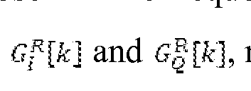
refers to the conjugate of a complex

number. Define

Reference signals may be designed as follows, and transmitted in two disjoint time intervals:
Reference
 The corresponding received symbols on subcarrier k and - k at the output of the fast Fourier transform block are given by

Reference
 The corresponding received symbols on subcarrier k and - k at the output of the fast Fourier transform block are given by

where are the noise terms.

I/Q imbalance estimation for the receiver is then performed. The estimation method may, for example, be least squares estimation, given by

I/Q imbalance of the receiver may then be compensated in the frequency domain or the time domain at the digital baseband of the receiver.
Fig. 6 presents a data processing element 600 that may be used in a transceiver such as the transceiver 100 to perform I/Q imbalance estimation and compensation. Multiple data processing elements such as the element 600 may be employed, or a single element
may independently serve different components of the transceiver 100, such as the transmitter 102 or the receiver 104.
The data processing element 600 may include a processor 608 and memory 610. The data processing element 600 may employ data 612 and programs (PROGS) 614, residing in memory 610.
At least one of the PROGs 614 in the data processing element 600 is assumed to include a set of program instructions that, when executed by the associated processor 608, enable the data processing element to operate in accordance with embodiments of this invention. In these regards, embodiments of this invention may be implemented at least in part by computer software stored on the MEM 610, which is executable by the processor 608 of the data processing element 600, or by hardware, or by a combination of tangibly stored software and hardware (and tangibly stored firmware). Electronic devices implementing these aspects of the invention need not be the entire devices as depicted at Figure 1 or Fig. 6 or may be one or more components of same such as the above described tangibly stored software, hardware, firmware and processor, or a system on a chip SOC or an application specific integrated circuit ASIC.
Various embodiments of the computer readable MEM 610 include any data storage technology type which is suitable to the local technical environment, including but not limited to semiconductor based memory devices, magnetic memory devices and systems, optical memory devices and systems, fixed memory, removable memory, disc memory, flash memory, DRAM, SRAM, EEPROM and the like. Various embodiments of the processor 408 include but are not limited to general purpose computers, special purpose computers, microprocessors, digital signal processors (DSPs) and multi-core processors.
Various modifications and adaptations to the foregoing exemplary embodiments of this invention may become apparent to those skilled in the relevant arts in view of the foregoing description. While various exemplary embodiments have been described above it should be appreciated that the practice of the invention is not limited to the exemplary embodiments shown and discussed here.
Further, some of the various features of the above non-limiting embodiments may be used to advantage without the corresponding use of other described features. The foregoing description should therefore be considered as merely illustrative of the
principles, teachings and exemplary embodiments of this invention, and not in limitation thereof.
Various modifications and adaptations to the foregoing exemplary embodiments of this invention may become apparent to those skilled in the relevant arts in view of the foregoing description. While various exemplary embodiments have been described above it should be appreciated that the practice of the invention is not limited to the exemplary embodiments shown and discussed here.
Further, some of the various features of the above non-limiting embodiments may be used to advantage without the corresponding use of other described features. The foregoing description should therefore be considered as merely illustrative of the principles, teachings and exemplary embodiments of this invention, and not in limitation thereof.
Claims
1. An apparatus comprising:
at least one processor;
memory storing a program of instructions;
wherein the memory storing the program of instructions is configured to, with the at least one processor, cause the apparatus to at least:
estimate in-phase/quadrature (I/Q) imbalance for a transmitter of a transceiver based on specified reference signals for transmitter estimation, with reference signals being sequentially received via only the I-branch of the receiver and only the Q-branch of the receiver;
compensate the I/Q imbalance of the transmitter;
estimate I/Q imbalance for a receiver of the transceiver based on specified reference signals for receiver estimation with reference signals being received by both the I-branch and Q-branch of the receiver;
wherein estimating the I/Q imbalance for the receiver comprises transmitting the receiver reference signals using a transmitter output produced when the I/Q imbalance of the transmitter has been fully compensated; and
compensating the I/Q imbalance of the receiver.
2. The apparatus of claim 1, wherein estimating I/Q imbalance of the transmitter comprises receiving a first set of reference signals at the I-branch of the receiver and a second set of reference signals at the Q-branch of the receiver, and wherein estimating I/Q imbalance of the receiver comprises receiving a third set of reference signals at both the I- and Q- branches of the receiver.
3. The apparatus of claim 1 or 2, wherein the transceiver is configured to enable internal loopback for I/Q imbalance estimation, and to disable internal loopback for data communication.
4. The apparatus of claim 1, 2, or 3, wherein each set of reference signals is a pair of reference signals, and wherein the reference signals of a pair are transmitted in two disjoint time intervals.
5. The apparatus of claim 1, 2, 3, or 4, wherein I/Q imbalance estimation is least squares estimation.
6. A method comprising:
estimating in-phase/quadrature (I/Q) imbalance for a transmitter of a transceiver based on specified reference signals for transmitter estimation, with reference signals being sequentially received via only the I-branch of the receiver and only the Q-branch of the receiver;
compensating the I/Q imbalance of the transmitter;
estimating I/Q imbalance for a receiver of the transceiver based on specified reference signals for receiver estimation with reference signals being received by both the I-branch and Q-branch of the receiver;
wherein estimating the I/Q imbalance for the receiver comprises transmitting the receiver reference signals using a transmitter output produced when the I/Q imbalance of the transmitter has been fully compensated; and
compensating the I/Q imbalance of the receiver.
7. The method of claim 6, wherein estimating I/Q imbalance of the transmitter comprises receiving a first set of reference signals at the I-branch of the receiver and a second set of reference signals at the Q-branch of the receiver, and wherein estimating I/Q imbalance of the receiver comprises receiving a third set of reference signals at both the I- and Q- branches of the receiver.
8. The method of claim 6 or 7, wherein the transceiver is configured to enable internal loopback for I/Q imbalance estimation, and to disable internal loopback for data communication.
9. The method of claim 6, 7, or 8, wherein each set of reference signals is a pair of reference signals, and wherein the reference signals of a pair are transmitted in two disjoint time intervals.
10. The method of claim 6, 7, 8, or 9, wherein I/Q imbalance estimation is least squares estimation.
11. A non-transitory computer-readable medium storing a program of instructions execution of which by at least one processor configures an apparatus to at least:
estimate in-phase/quadrature (I/Q) imbalance for a transmitter of a transceiver based on specified reference signals for transmitter estimation, with reference signals being
sequentially received via only the I-branch of the receiver and only the Q-branch of the receiver;
compensate the I/Q imbalance of the transmitter;
estimate I/Q imbalance for a receiver of the transceiver based on specified reference signals for receiver estimation with reference signals being received by both the I-branch and Q-branch of the receiver;
wherein estimating the I/Q imbalance for the receiver comprises transmitting the receiver reference signals using a transmitter output produced when the I/Q imbalance of the transmitter has been fully compensated; and
compensating the I/Q imbalance of the receiver.
12. The non-transitory computer-readable medium of claim 11 , wherein estimating I/Q imbalance of the transmitter comprises receiving a first set of reference signals at the I-branch of the receiver and a second set of reference signals at the Q-branch of the receiver, and wherein estimating I/Q imbalance of the receiver comprises receiving a third set of reference signals at both the I- and Q- branches of the receiver.
13. The non-transitory computer-readable medium of claim 11 or 12, wherein the transceiver is configured to enable internal loopback for I/Q imbalance estimation, and to disable internal loopback for data communication.
14. The non-transitory computer-readable medium of claim 11, 12, or 13, wherein each set of reference signals is a pair of reference signals, and wherein the reference signals of a pair are transmitted in two disjoint time intervals.
15. The non-transitory computer-readable medium of claim 11, 12, 13, or 14, wherein I/Q imbalance estimation is least squares estimation.
Applications Claiming Priority (2)
| Application Number | Priority Date | Filing Date | Title |
|---|---|---|---|
| US14/698,088 | 2015-04-28 | ||
| US14/698,088 US20160323010A1 (en) | 2015-04-28 | 2015-04-28 | Methods and apparatus for mitigation of radio-frequency impairments in wireless network communication |
Publications (1)
| Publication Number | Publication Date |
|---|---|
| WO2016174305A1 true WO2016174305A1 (en) | 2016-11-03 |
Family
ID=55948852
Family Applications (1)
| Application Number | Title | Priority Date | Filing Date |
|---|---|---|---|
| PCT/FI2016/050267 Ceased WO2016174305A1 (en) | 2015-04-28 | 2016-04-25 | Methods and apparatus for mitigation of i/q imbalance in wireless communication network |
Country Status (2)
| Country | Link |
|---|---|
| US (1) | US20160323010A1 (en) |
| WO (1) | WO2016174305A1 (en) |
Families Citing this family (11)
| Publication number | Priority date | Publication date | Assignee | Title |
|---|---|---|---|---|
| US9438178B1 (en) * | 2015-09-02 | 2016-09-06 | Intel IP Corporation | Mixer impairment correction based on volterra series |
| US10958217B2 (en) * | 2017-12-14 | 2021-03-23 | U-Blox Ag | Methods, circuits, and apparatus for calibrating an in-phase and quadrature imbalance |
| EP3503488B1 (en) * | 2017-12-19 | 2020-06-10 | National Chung Shan Institute of Science and Technology | I/q imbalance calibration apparatus, method and transmitter system using the same |
| TWI657670B (en) * | 2017-12-26 | 2019-04-21 | 國家中山科學研究院 | I/Q imbalance calibration device |
| TWI657671B (en) * | 2017-12-26 | 2019-04-21 | 國家中山科學研究院 | I/Q imbalance calibration device |
| US10778344B2 (en) | 2018-11-14 | 2020-09-15 | Texas Instruments Incorporated | Channel tracking method and module |
| US11374669B2 (en) | 2018-11-28 | 2022-06-28 | Texas Instruments Incorporated | Phase spectrum based delay estimation method and module |
| US11095485B2 (en) * | 2018-11-30 | 2021-08-17 | Texas Instruments Incorporated | Frequency-domain IQ mismatch estimation |
| JP7028295B1 (en) | 2020-09-23 | 2022-03-02 | 沖電気工業株式会社 | Transmission device, receiving side transmission device and transmission method |
| US11438122B2 (en) * | 2021-06-14 | 2022-09-06 | Ultralogic 6G, Llc | Custom downlink search-spaces for low-complexity 5G/6G messaging |
| CN113556303B (en) * | 2021-07-19 | 2023-09-05 | 上海擎昆信息科技有限公司 | IQ compensation method and device for single carrier transceiver and single carrier transceiver |
Citations (2)
| Publication number | Priority date | Publication date | Assignee | Title |
|---|---|---|---|---|
| US20040203472A1 (en) * | 2002-09-05 | 2004-10-14 | G-Plus, Inc. | Compensation of I-Q imbalance in digital transceivers |
| EP2568617A1 (en) * | 2011-09-06 | 2013-03-13 | Research In Motion Limited | Wireless communications device with performance monitoring and associated methods |
Family Cites Families (6)
| Publication number | Priority date | Publication date | Assignee | Title |
|---|---|---|---|---|
| EP1624636B1 (en) * | 2004-08-05 | 2008-07-09 | STMicroelectronics S.r.l. | Method and apparatus for receiving an OFDM signal and compensating IQ imbalance and frequency offset |
| US7620373B2 (en) * | 2006-06-23 | 2009-11-17 | Sierra Monolithics, Inc. | Apparatus and method for calibration of gain and/or phase imbalance and/or DC offset in a communication system |
| US7856048B1 (en) * | 2006-11-20 | 2010-12-21 | Marvell International, Ltd. | On-chip IQ imbalance and LO leakage calibration for transceivers |
| US8000382B2 (en) * | 2008-01-04 | 2011-08-16 | Qualcomm Incorporated | I/Q imbalance estimation and correction in a communication system |
| US20110013724A1 (en) * | 2009-04-24 | 2011-01-20 | Qualcomm Incorporated | I/q imbalance estimation and compensation for a transmitter and a receiver |
| US20120300818A1 (en) * | 2011-03-31 | 2012-11-29 | Qualcomm Incorporated | Self-calibration i/q imbalance reduction |
-
2015
- 2015-04-28 US US14/698,088 patent/US20160323010A1/en not_active Abandoned
-
2016
- 2016-04-25 WO PCT/FI2016/050267 patent/WO2016174305A1/en not_active Ceased
Patent Citations (2)
| Publication number | Priority date | Publication date | Assignee | Title |
|---|---|---|---|---|
| US20040203472A1 (en) * | 2002-09-05 | 2004-10-14 | G-Plus, Inc. | Compensation of I-Q imbalance in digital transceivers |
| EP2568617A1 (en) * | 2011-09-06 | 2013-03-13 | Research In Motion Limited | Wireless communications device with performance monitoring and associated methods |
Also Published As
| Publication number | Publication date |
|---|---|
| US20160323010A1 (en) | 2016-11-03 |
Similar Documents
| Publication | Publication Date | Title |
|---|---|---|
| US20160323010A1 (en) | Methods and apparatus for mitigation of radio-frequency impairments in wireless network communication | |
| US9621337B2 (en) | Adaptive I/O mismatch calibration | |
| US10116485B1 (en) | TX/RX imbalance and carrier leakage calibration | |
| RU2515282C1 (en) | Inter-carrier bandwidth control for mitigating iq imbalance | |
| US7248625B2 (en) | Compensation of I-Q imbalance in digital transceivers | |
| KR101455894B1 (en) | Imbalance compensation for direct conversion communication systems | |
| CN106664278B (en) | Phase noise estimation and compensation | |
| US10389561B2 (en) | Transmitter time-domain estimation and compensation of IQ imbalance | |
| US20130259173A1 (en) | Receiver-side estimation of and compensation for signal impairments | |
| US20180242269A1 (en) | System and method for iq mismatch calibration and compensation | |
| US11539570B2 (en) | I/Q imbalance compensation | |
| US20080273608A1 (en) | Method and Apparatus for Correcting IQ Imbalance in an OFDM Receiver | |
| US20150350000A1 (en) | Calibration method and calibration apparatus for calibrating mismatch between first signal path and second signal path of transmitter/receiver | |
| Samara et al. | Residual self-interference analysis for full-duplex OFDM transceivers under phase noise and I/Q imbalance | |
| US9237043B1 (en) | Method and apparatus to provide simultaneous sensing and transmission for dynamic spectrum access | |
| CN112887238A (en) | IQ imbalance correction method and device, and receiver | |
| US20140018014A1 (en) | Transceiver Device | |
| US8085863B2 (en) | Radio receiver or transmitter and method for reducing an IQ gain imbalance | |
| WO2013105538A1 (en) | Method for iq mismatch compensation, and rf transceiver device | |
| US9698917B2 (en) | Methods and apparatus for mitigation of radio-frequency impairments in wireless network communication | |
| US20070047672A1 (en) | Apparatus and method for compensating for I/Q mismatch in TDD system | |
| WO2015122098A1 (en) | ORTHOGONAL MODULATION AND DEMODULATION METHOD AND DEVICE USING COMPLEMENTARY Golay CODE | |
| EP3335391B1 (en) | Homodyne receiver calibration | |
| Abd Aziz et al. | A Comparative Study of In-phase and Quadrature (IQ) Imbalance Estimation and Compensation Algorithms for OFDM Receivers | |
| US20180248742A1 (en) | Non-Disruptive IQ Mismatch Calibration |
Legal Events
| Date | Code | Title | Description |
|---|---|---|---|
| 121 | Ep: the epo has been informed by wipo that ep was designated in this application |
Ref document number: 16721192 Country of ref document: EP Kind code of ref document: A1 |
|
| NENP | Non-entry into the national phase |
Ref country code: DE |
|
| 122 | Ep: pct application non-entry in european phase |
Ref document number: 16721192 Country of ref document: EP Kind code of ref document: A1 |