WO2016167138A1 - Programme, dispositif et procédé de traitement de signal - Google Patents
Programme, dispositif et procédé de traitement de signal Download PDFInfo
- Publication number
- WO2016167138A1 WO2016167138A1 PCT/JP2016/060895 JP2016060895W WO2016167138A1 WO 2016167138 A1 WO2016167138 A1 WO 2016167138A1 JP 2016060895 W JP2016060895 W JP 2016060895W WO 2016167138 A1 WO2016167138 A1 WO 2016167138A1
- Authority
- WO
- WIPO (PCT)
- Prior art keywords
- spatial
- transfer characteristic
- spatial correction
- characteristic matrix
- correction information
- Prior art date
Links
- 238000000034 method Methods 0.000 title claims abstract description 220
- 238000012545 processing Methods 0.000 title claims abstract description 110
- 239000011159 matrix material Substances 0.000 claims abstract description 328
- 238000012937 correction Methods 0.000 claims description 397
- 238000012546 transfer Methods 0.000 claims description 337
- 230000008569 process Effects 0.000 claims description 67
- 230000005236 sound signal Effects 0.000 claims description 65
- 238000003672 processing method Methods 0.000 claims description 19
- 238000005516 engineering process Methods 0.000 abstract description 24
- 230000005540 biological transmission Effects 0.000 abstract description 9
- 238000001228 spectrum Methods 0.000 description 56
- 238000004364 calculation method Methods 0.000 description 43
- 238000004458 analytical method Methods 0.000 description 31
- 230000015572 biosynthetic process Effects 0.000 description 24
- 238000003786 synthesis reaction Methods 0.000 description 24
- 238000004891 communication Methods 0.000 description 21
- 238000006243 chemical reaction Methods 0.000 description 20
- 230000007274 generation of a signal involved in cell-cell signaling Effects 0.000 description 15
- 230000002123 temporal effect Effects 0.000 description 15
- 230000006870 function Effects 0.000 description 9
- 238000005070 sampling Methods 0.000 description 7
- 238000005259 measurement Methods 0.000 description 6
- 239000000284 extract Substances 0.000 description 5
- 230000000694 effects Effects 0.000 description 4
- 230000007423 decrease Effects 0.000 description 3
- 230000001771 impaired effect Effects 0.000 description 3
- 230000006872 improvement Effects 0.000 description 3
- 238000013459 approach Methods 0.000 description 2
- 238000003491 array Methods 0.000 description 2
- 230000008901 benefit Effects 0.000 description 2
- 230000015556 catabolic process Effects 0.000 description 2
- 239000012141 concentrate Substances 0.000 description 2
- 238000006731 degradation reaction Methods 0.000 description 2
- 238000010586 diagram Methods 0.000 description 2
- 125000004122 cyclic group Chemical group 0.000 description 1
- 238000004519 manufacturing process Methods 0.000 description 1
- 238000012986 modification Methods 0.000 description 1
- 230000004048 modification Effects 0.000 description 1
- 230000003287 optical effect Effects 0.000 description 1
- 230000001151 other effect Effects 0.000 description 1
- 230000000717 retained effect Effects 0.000 description 1
- 239000004065 semiconductor Substances 0.000 description 1
- 230000003595 spectral effect Effects 0.000 description 1
- 239000013598 vector Substances 0.000 description 1
Images
Classifications
-
- G—PHYSICS
- G10—MUSICAL INSTRUMENTS; ACOUSTICS
- G10K—SOUND-PRODUCING DEVICES; METHODS OR DEVICES FOR PROTECTING AGAINST, OR FOR DAMPING, NOISE OR OTHER ACOUSTIC WAVES IN GENERAL; ACOUSTICS NOT OTHERWISE PROVIDED FOR
- G10K15/00—Acoustics not otherwise provided for
- G10K15/08—Arrangements for producing a reverberation or echo sound
- G10K15/12—Arrangements for producing a reverberation or echo sound using electronic time-delay networks
-
- G—PHYSICS
- G10—MUSICAL INSTRUMENTS; ACOUSTICS
- G10K—SOUND-PRODUCING DEVICES; METHODS OR DEVICES FOR PROTECTING AGAINST, OR FOR DAMPING, NOISE OR OTHER ACOUSTIC WAVES IN GENERAL; ACOUSTICS NOT OTHERWISE PROVIDED FOR
- G10K15/00—Acoustics not otherwise provided for
- G10K15/02—Synthesis of acoustic waves
-
- G—PHYSICS
- G10—MUSICAL INSTRUMENTS; ACOUSTICS
- G10K—SOUND-PRODUCING DEVICES; METHODS OR DEVICES FOR PROTECTING AGAINST, OR FOR DAMPING, NOISE OR OTHER ACOUSTIC WAVES IN GENERAL; ACOUSTICS NOT OTHERWISE PROVIDED FOR
- G10K15/00—Acoustics not otherwise provided for
- G10K15/08—Arrangements for producing a reverberation or echo sound
-
- H—ELECTRICITY
- H04—ELECTRIC COMMUNICATION TECHNIQUE
- H04R—LOUDSPEAKERS, MICROPHONES, GRAMOPHONE PICK-UPS OR LIKE ACOUSTIC ELECTROMECHANICAL TRANSDUCERS; DEAF-AID SETS; PUBLIC ADDRESS SYSTEMS
- H04R1/00—Details of transducers, loudspeakers or microphones
- H04R1/20—Arrangements for obtaining desired frequency or directional characteristics
- H04R1/32—Arrangements for obtaining desired frequency or directional characteristics for obtaining desired directional characteristic only
- H04R1/40—Arrangements for obtaining desired frequency or directional characteristics for obtaining desired directional characteristic only by combining a number of identical transducers
-
- H—ELECTRICITY
- H04—ELECTRIC COMMUNICATION TECHNIQUE
- H04R—LOUDSPEAKERS, MICROPHONES, GRAMOPHONE PICK-UPS OR LIKE ACOUSTIC ELECTROMECHANICAL TRANSDUCERS; DEAF-AID SETS; PUBLIC ADDRESS SYSTEMS
- H04R3/00—Circuits for transducers, loudspeakers or microphones
- H04R3/04—Circuits for transducers, loudspeakers or microphones for correcting frequency response
-
- H—ELECTRICITY
- H04—ELECTRIC COMMUNICATION TECHNIQUE
- H04S—STEREOPHONIC SYSTEMS
- H04S7/00—Indicating arrangements; Control arrangements, e.g. balance control
- H04S7/30—Control circuits for electronic adaptation of the sound field
- H04S7/307—Frequency adjustment, e.g. tone control
-
- G—PHYSICS
- G10—MUSICAL INSTRUMENTS; ACOUSTICS
- G10L—SPEECH ANALYSIS TECHNIQUES OR SPEECH SYNTHESIS; SPEECH RECOGNITION; SPEECH OR VOICE PROCESSING TECHNIQUES; SPEECH OR AUDIO CODING OR DECODING
- G10L19/00—Speech or audio signals analysis-synthesis techniques for redundancy reduction, e.g. in vocoders; Coding or decoding of speech or audio signals, using source filter models or psychoacoustic analysis
- G10L19/008—Multichannel audio signal coding or decoding using interchannel correlation to reduce redundancy, e.g. joint-stereo, intensity-coding or matrixing
-
- G—PHYSICS
- G10—MUSICAL INSTRUMENTS; ACOUSTICS
- G10L—SPEECH ANALYSIS TECHNIQUES OR SPEECH SYNTHESIS; SPEECH RECOGNITION; SPEECH OR VOICE PROCESSING TECHNIQUES; SPEECH OR AUDIO CODING OR DECODING
- G10L21/00—Speech or voice signal processing techniques to produce another audible or non-audible signal, e.g. visual or tactile, in order to modify its quality or its intelligibility
- G10L21/02—Speech enhancement, e.g. noise reduction or echo cancellation
- G10L21/0208—Noise filtering
- G10L21/0216—Noise filtering characterised by the method used for estimating noise
- G10L2021/02161—Number of inputs available containing the signal or the noise to be suppressed
- G10L2021/02166—Microphone arrays; Beamforming
-
- H—ELECTRICITY
- H04—ELECTRIC COMMUNICATION TECHNIQUE
- H04R—LOUDSPEAKERS, MICROPHONES, GRAMOPHONE PICK-UPS OR LIKE ACOUSTIC ELECTROMECHANICAL TRANSDUCERS; DEAF-AID SETS; PUBLIC ADDRESS SYSTEMS
- H04R1/00—Details of transducers, loudspeakers or microphones
- H04R1/20—Arrangements for obtaining desired frequency or directional characteristics
- H04R1/32—Arrangements for obtaining desired frequency or directional characteristics for obtaining desired directional characteristic only
- H04R1/40—Arrangements for obtaining desired frequency or directional characteristics for obtaining desired directional characteristic only by combining a number of identical transducers
- H04R1/406—Arrangements for obtaining desired frequency or directional characteristics for obtaining desired directional characteristic only by combining a number of identical transducers microphones
-
- H—ELECTRICITY
- H04—ELECTRIC COMMUNICATION TECHNIQUE
- H04R—LOUDSPEAKERS, MICROPHONES, GRAMOPHONE PICK-UPS OR LIKE ACOUSTIC ELECTROMECHANICAL TRANSDUCERS; DEAF-AID SETS; PUBLIC ADDRESS SYSTEMS
- H04R2201/00—Details of transducers, loudspeakers or microphones covered by H04R1/00 but not provided for in any of its subgroups
- H04R2201/40—Details of arrangements for obtaining desired directional characteristic by combining a number of identical transducers covered by H04R1/40 but not provided for in any of its subgroups
- H04R2201/403—Linear arrays of transducers
-
- H—ELECTRICITY
- H04—ELECTRIC COMMUNICATION TECHNIQUE
- H04R—LOUDSPEAKERS, MICROPHONES, GRAMOPHONE PICK-UPS OR LIKE ACOUSTIC ELECTROMECHANICAL TRANSDUCERS; DEAF-AID SETS; PUBLIC ADDRESS SYSTEMS
- H04R3/00—Circuits for transducers, loudspeakers or microphones
- H04R3/12—Circuits for transducers, loudspeakers or microphones for distributing signals to two or more loudspeakers
-
- H—ELECTRICITY
- H04—ELECTRIC COMMUNICATION TECHNIQUE
- H04S—STEREOPHONIC SYSTEMS
- H04S2420/00—Techniques used stereophonic systems covered by H04S but not provided for in its groups
- H04S2420/01—Enhancing the perception of the sound image or of the spatial distribution using head related transfer functions [HRTF's] or equivalents thereof, e.g. interaural time difference [ITD] or interaural level difference [ILD]
Definitions
- the present technology relates to a signal processing device, method, and program, and more particularly, to a signal processing device, method, and program that can reproduce a sound field more appropriately according to content.
- Non-Patent Document 1 As a technique related to such a sound field reproduction, there is a technique for reducing the amount of calculation at the time of calculating a speaker drive signal for outputting sound by a speaker array by performing spatial frequency conversion and diagonalizing a transfer function matrix. It has been proposed (see Non-Patent Document 1, for example).
- Non-Patent Document 1 assumes ideal spatial transfer characteristics in free space, so that the spatial reproducibility of the sound field may deteriorate depending on the reproduction environment.
- Such a decrease in the spatial reproducibility of the sound field can be suppressed by performing spatial correction processing by measuring the spatial transmission characteristics of the sound including reflection and reverberation in the reproduction space.
- Non-Patent Document 2 a technique using an actual spatial transfer characteristic for calculation of a speaker drive signal has been proposed (for example, see Non-Patent Document 2).
- the spatial transfer characteristics from each speaker to the observation point (control point) are time-frequency converted, and the pseudo-inverse matrix of the spatial transfer characteristic matrix is calculated for each time frequency. Calculated.
- Non-Patent Document 2 in order to obtain a speaker drive signal, it is necessary to always perform matrix calculation using all elements of the spatial transfer characteristic matrix for each time frequency, and the amount of calculation is large. It will increase. In particular, a large-scale system with a large number of channels requires more calculations.
- the present technology has been made in view of such a situation, and makes it possible to reproduce a sound field more appropriately according to content.
- the signal processing device includes an acquisition unit that acquires a multi-channel audio signal obtained by collecting sound with a microphone array, and a plurality of spatial transfer characteristics that are corrected based on the spatial correction information.
- a spatial correction method selection unit that selects one spatial correction method from the spatial correction method, and a spatial correction processing unit that performs spatial correction processing on the audio signal based on the spatial transfer characteristic matrix of the selected spatial correction method.
- the spatial correction information can be information indicating the priority of the spatial correction processing.
- the spatial correction method selection unit can select the spatial correction method based on the spatial correction information and the number of speakers constituting a speaker array that outputs sound based on the audio signal.
- the spatial correction method selection unit can select the spatial correction method based on the spatial correction information and the calculation capability of the signal processing device.
- the plurality of the spatial correction methods can be configured such that the calculation amount of the spatial correction processing is different from each other.
- the spatial transfer characteristic matrix can be obtained by extracting a part or all of the matrix indicating the spatial transfer characteristic of the space where the sound based on the audio signal is reproduced.
- the spatial transfer characteristic matrix of the plurality of spatial correction methods is obtained by extracting only the spatial transfer characteristic matrix obtained by extracting at least the diagonal component of the matrix and only the tridiagonal component of the matrix. At least one of the obtained spatial transfer characteristic matrix, the spatial transfer characteristic matrix obtained by extracting only a specific block of the matrix, and the spatial transfer characteristic matrix that is the matrix. Can do.
- the spatial correction information can be determined in a predetermined time unit for the audio signal.
- the acquisition unit can acquire the spatial correction information together with the audio signal.
- a signal processing method or program acquires a multi-channel audio signal obtained by collecting sound with a microphone array, and corrects spatial transfer characteristics based on spatial correction information. Selecting a spatial correction method from the correction methods, and performing a spatial correction process on the audio signal based on the spatial transfer characteristic matrix of the selected spatial correction method.
- a multi-channel audio signal obtained by sound collection by a microphone array is acquired, and one of a plurality of spatial correction methods for correcting spatial transfer characteristics based on spatial correction information is provided.
- a spatial correction method is selected, and a spatial correction process is performed on the audio signal based on the spatial transfer characteristic matrix of the selected spatial correction method.
- a signal processing device is for selecting a spatial correction processing method for correcting a spatial transfer characteristic performed on a multi-channel audio signal obtained by collecting sound with a microphone array.
- An acquisition unit that acquires spatial correction information, and an output unit that outputs the audio signal and the spatial correction information.
- the spatial correction information can be information indicating the priority of the spatial correction processing.
- the spatial correction information can be determined in a predetermined time unit for the audio signal.
- the signal processing method or program according to the second aspect of the present technology selects a spatial correction processing method that corrects spatial transfer characteristics performed on a multi-channel audio signal obtained by collecting sound with a microphone array. Obtaining the spatial correction information for outputting the audio signal and the spatial correction information.
- the sound field can be reproduced more appropriately according to the content.
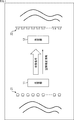
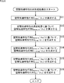
- the present technology records a sound field by a microphone array including a plurality of microphones in a real space (sound collection space), and a plurality of speakers arranged in a reproduction space based on a multichannel sound collection signal obtained as a result.
- the sound field is reproduced by a speaker array consisting of
- the present technology together with the sound collection signal obtained by collecting the sound field, a space indicating the degree of necessity of the spatial correction processing in the content to be reproduced, that is, the priority of the spatial correction processing.
- the correction information flg is also transmitted to the playback space side.
- a transmitter 11 that functions as an encoding device is disposed in the sound collection space
- a receiver 12 that functions as a decoding device is disposed in the reproduction space.
- the transmitter 11 has a linear microphone array 21 composed of a plurality of microphones arranged in a straight line, and the voice (sound field) in the sound collection space is collected as content by the linear microphone array 21.
- the transmitter 11 records the spatial correction information flg input by the content producer or the like for each content.
- the spatial correction information flg indicates the degree to which the calculation resources should be concentrated on the spatial correction processing, that is, the priority of the spatial correction processing in the entire processing for reproducing the content, and the value of the spatial correction information flg is large. It shows that the priority is high. In other words, as the value of the spatial correction information flg is larger, it is indicated that the spatial correction process of the spatial correction method with a larger amount of calculation should be performed to improve the spatial reproducibility of the content.
- the value of the spatial correction information flg given by the content producer or the like may be defined as a discrete value such as 4 levels of 0 to 3, or may be defined as a continuous value.
- the spatial correction information flg is defined as a discrete value
- the value of the spatial correction information flg is 0 when no spatial correction is required, and 1 when correction of speaker characteristics and direct sound spatial transfer characteristics is required. 2 when the initial reflection from the wall parallel to the speaker array such as the ceiling or floor is required, and 3 when the reflection from the left and right walls perpendicular to the speaker array is required. It can be.
- the spatial correction information flg may be defined based on the priority of sound quality reproducibility.
- the spatial correction information flg is a value indicating the priority of the spatial correction processing
- the spatial correction information flg is an index for selecting a spatial correction processing method, that is, a spatial correction method. Any information may be used as long as it is information.
- the spatial correction information flg may be the spatial transfer characteristic matrix itself used for the spatial correction processing.
- the transmitter 11 transmits the collected sound signal of the content obtained by collecting sound and the spatial correction information flg of the content to the receiver 12.
- the receiver 12 arranged in the reproduction space has a linear speaker array 22 composed of a plurality of speakers arranged in a straight line.
- the receiver 12 When the receiver 12 receives the collected sound signal and the spatial correction information flg transmitted from the transmitter 11, the receiver 12 performs spatial correction processing of the spatial correction method according to the spatial correction information flg on the collected signal, and obtains the result. Based on the obtained speaker drive signal, the linear speaker array 22 outputs sound. Thereby, the sound field of the sound collection space is reproduced. That is, the content is played back.
- the spatial correction information flg is transmitted together with the sound collection signal in this way, it is possible to select a spatial correction process of an optimum method step by step according to the content and adjust the amount of calculation of the spatial correction process.
- the spatial correction information flg is determined and transmitted with respect to the content (sound collecting signal) in a predetermined time unit, the amount of calculation can be adjusted by switching the spatial correction processing method in the predetermined time unit. . As a result, more appropriate sound field reproduction can be realized according to the content, the scene of the content, and the like.
- the predetermined time unit can be an arbitrary fixed or variable time interval such as for each content, for each scene of the content, or for each transmission frame of the collected sound signal.
- the spatial correction information flg is switched in units of content
- the spatial correction information flg is switched in accordance with the channel switching of the television program, so that the spatial correction processing of the optimal spatial correction method is performed for each television program.
- an advantage of the transmitter 11 is that the intention of the content creator in reproducing the sound field can be transmitted to the reproduction side by the spatial correction information flg. It is done.
- the sound field can be reproduced more appropriately by adjusting the calculation amount of the spatial correction processing in consideration of not only the contents but also the calculation resources of the receiver 12.
- the vertical axis indicates the venue where the sound field as the content is collected, that is, the size of the sound collection space, and indicates that the venue is larger toward the lower side in the figure.
- the horizontal axis indicates the magnitude of reflection and reverberation at the venue where the content is collected, and the reflection and reverberation increase toward the right side in the figure.
- the content producer specifies, as his intention, whether to emphasize sound quality during content reproduction or to emphasize spatial reproducibility such as reflection and reverberation.
- content creators may consider adding spatial correction information flg that emphasizes spatial reproducibility during content playback. It is done. By doing so, on the receiver 12 side, calculation resources can be concentrated on the spatial correction processing, and the content can be reproduced with high spatial reproducibility according to the intention of the content producer.
- the receiver 12 requires fewer calculation resources for the spatial correction process, and accordingly, the calculation resources are concentrated on the sound quality improvement process to improve the sound quality reproducibility. Arithmetic resources can be allocated.
- the content producer should give the spatial correction information flg in consideration of the balance between spatial reproducibility and sound quality reproducibility. .
- the content creator can transmit the spatial correction information flg indicating the priority of the spatial correction processing to the playback side, and emphasize sound quality reproducibility according to the content, or spatial reproduction. You can reflect your intentions such as emphasizing sex.
- the spatial correction information flg can be specified in a predetermined time unit, when the priority of the spatial correction processing is low in the receiver 12, a sound with a higher degree of freedom such as allocating computation resources to other processing. Field reproduction can be realized.
- the receiver 12 may select the spatial correction processing method based on the spatial correction information flg and its own computation resource.
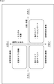
- FIG. 3 is a diagram illustrating a configuration example of an embodiment of a spatial correction controller to which the present technology is applied.
- the same reference numerals are given to the portions corresponding to those in FIG. 1, and the description thereof will be omitted as appropriate.
- the space correction controller 51 includes a transmitter 11 disposed in the sound collection space and a receiver 12 disposed in the reproduction space.
- the transmitter 11 is a signal processing device that functions as an encoding device
- the receiver 12 is a signal processing device that functions as a decoding device.
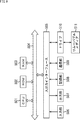
- the transmitter 11 includes a linear microphone array 21, a time frequency analysis unit 61, a spatial frequency analysis unit 62, an encoding unit 63, and a communication unit 64.
- the linear microphone array 21 collects sound in the sound collection space as content, and supplies a sound collection signal, which is a multi-channel sound signal obtained as a result, to the time-frequency analysis unit 61.
- the time frequency analysis unit 61 performs time frequency conversion on the collected sound signal supplied from the linear microphone array 21 and supplies the time frequency spectrum obtained as a result to the spatial frequency analysis unit 62.
- the spatial frequency analysis unit 62 performs spatial frequency conversion on the temporal frequency spectrum supplied from the temporal frequency analysis unit 61, and supplies the spatial frequency spectrum obtained as a result to the encoding unit 63.
- the encoding unit 63 encodes the spatial frequency spectrum supplied from the spatial frequency analysis unit 62 and the spatial correction information flg input by the content producer or the like, and sends the multiplexed signal obtained as a result to the communication unit 64. Supply.
- the communication unit 64 transmits the multiplexed signal supplied from the encoding unit 63 to the receiver 12 by wire or wireless.
- the receiver 12 includes a communication unit 65, a decoding unit 66, a spatial correction method selection unit 67, a spatial transfer characteristic matrix generation unit 68, a drive signal generation unit 69, a spatial frequency synthesis unit 70, a time frequency synthesis unit 71, and a straight line.
- a speaker array 22 is provided.
- the communication unit 65 receives the multiplexed signal transmitted from the communication unit 64 and supplies it to the decoding unit 66.
- the decoding unit 66 extracts the spatial frequency spectrum and the spatial correction information flg from the multiplexed signal by decoding the multiplexed signal supplied from the communication unit 65.
- the decoding unit 66 supplies the spatial correction information flg obtained by decoding to the spatial correction method selection unit 67 and supplies the spatial frequency spectrum obtained by decoding to the drive signal generation unit 69.
- the spatial correction method selection unit 67 calculates a speaker drive signal for reproducing sound by the linear speaker array 22 from the spatial frequency spectrum of the collected sound signal based on the spatial correction information flg supplied from the decoding unit 66.
- the method of spatial correction processing (spatial correction method) to be performed is selected, and the selection result is supplied to the spatial transfer characteristic matrix generation unit 68.
- the spatial transfer characteristic matrix generation unit 68 supplies the drive signal generation unit 69 with a spatial transfer characteristic matrix indicating the spatial transfer characteristic according to the selection result of the spatial correction method supplied from the spatial correction method selection unit 67.
- the drive signal generation unit 69 performs a spatial correction process based on the spatial frequency spectrum supplied from the decoding unit 66 and the spatial transfer characteristic matrix supplied from the spatial transfer characteristic matrix generation unit 68, and simultaneously collects sound.
- the speaker drive signal in the spatial frequency domain for reproducing the sound field generated is generated and supplied to the spatial frequency synthesis unit 70.
- the spatial frequency synthesis unit 70 performs spatial frequency synthesis on the spatial frequency spectrum that is the speaker drive signal in the spatial frequency domain supplied from the drive signal generation unit 69, and uses the resulting time frequency spectrum as the time frequency synthesis unit. 71.
- the time-frequency synthesizer 71 performs time-frequency synthesis on the time-frequency spectrum supplied from the spatial frequency synthesizer 70, and supplies the speaker drive signal, which is a time signal obtained as a result, to the linear speaker array 22.
- the linear speaker array 22 reproduces sound based on the speaker drive signal supplied from the time frequency synthesis unit 71. Thereby, the sound field in the sound collection space is reproduced.
- the linear microphone array 21 as a microphone array which picks up sound in sound collection space is demonstrated here, in addition, if it is a microphone array which consists of several microphones, such as a spherical microphone array and a cyclic
- any speaker array that reproduces sound may be any speaker array including a plurality of speakers such as a spherical speaker array and an annular speaker array. It may be.
- the time-frequency analysis unit 61 performs time-frequency conversion on a multi-channel sound pickup signal s (i, n t ) obtained by each microphone that forms the linear microphone array 21 collecting sound. That is, the time-frequency analysis unit 61 performs time-frequency conversion using DFT (Discrete Fourier Transform) by performing the calculation of the following equation (1), and the collected sound signal s (i, nt) ) To obtain a time-frequency spectrum S (i, n tf ).
- DFT Discrete Fourier Transform
- N m indicates the number of microphones constituting the linear microphone array 21, and
- n t indicates a time index.
- n tf represents a time frequency index
- M t represents the number of DFT samples
- j represents a pure imaginary number
- the time frequency analysis unit 61 supplies the time frequency spectrum S (i, ntf ) obtained by the time frequency conversion to the spatial frequency analysis unit 62.
- the spatial frequency analysis unit 62 performs spatial frequency conversion on the temporal frequency spectrum S (i, n tf ) supplied from the temporal frequency analysis unit 61. That is, the spatial frequency analysis unit 62 performs the spatial frequency conversion using IDFT (Inverse Discrete Fourier Transform) by performing the calculation of the following equation (2), and the temporal frequency spectrum S (i, n The spatial frequency spectrum S SP (n tf , n sf ) is obtained from tf ).
- IDFT Inverse Discrete Fourier Transform
- n sf represents a spatial frequency index
- M s represents the number of IDFT samples.
- J represents a pure imaginary number.
- the spatial frequency analysis unit 62 supplies the spatial frequency spectrum S SP (n tf , n sf ) obtained by the spatial frequency conversion to the encoding unit 63.
- the encoding unit 63 acquires the spatial correction information flg input by the content producer or the like. Then, the encoding unit 63 encodes the acquired spatial correction information flg and the spatial frequency spectrum S SP (n tf , n sf ) supplied from the spatial frequency analysis unit 62, so that those spatial frequency spectra are obtained. A multiplexed signal in which S SP (n tf , n sf ) and spatial correction information flg are multiplexed is generated. The multiplexed signal obtained by the encoding unit 63 is output by the communication unit 64 and acquired by the decoding unit 66 via the communication unit 65.
- the temporal frequency spectrum of the collected sound signal may be transmitted to the receiver 12.
- bits can be preferentially assigned to the temporal frequency band and spatial frequency band that are important for sound field reproduction, so that the information is compressed further than when transmitting the temporal frequency spectrum. Can do.
- the decoding unit 66 acquires a multiplexed signal from the encoding unit 63 via the communication unit 65 and the communication unit 64.
- the decoding unit 66 decodes the acquired multiplexed signal, and extracts the spatial frequency spectrum S SP (n tf , n sf ) and the spatial correction information flg from the multiplexed signal.
- the decoding unit 66 supplies the obtained spatial frequency spectrum S SP (n tf , n sf ) to the drive signal generation unit 69 and supplies the spatial correction information flg to the spatial correction method selection unit 67.
- the spatial transfer characteristic matrix generation unit 68 supplies the drive signal generation unit 69 with a spatial transfer characteristic matrix according to the selection result of the spatial correction method supplied from the spatial correction method selection unit 67.
- the spatial transfer characteristic matrix may be generated in advance and held in the spatial transfer characteristic matrix generation unit 68, or may be generated by the spatial transfer characteristic matrix generation unit 68 after the spatial correction method is selected. You may make it do.
- the spatial transfer characteristic matrix is generated in advance will be described.
- the spatial transfer characteristic matrix G ideal '(n tf ), the spatial transfer characteristic matrix G diag ' (n tf ), and the spatial transfer characteristic matrix are used as the spatial transfer characteristic matrix for performing the spatial correction processing.
- G tridiag '(n tf ), spatial transfer characteristic matrix G block ' (n tf ), and spatial transfer characteristic matrix G all '(n tf ) are generated.
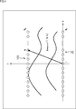
- a linear microphone for measuring spatial transfer characteristics is provided, in which a linear speaker array 22 is arranged in the reproduction space and the linear microphone array 21 is located at a predetermined distance from the linear speaker array 22. Assume that the array 101 is arranged.
- the linear speaker array in which the microphones constituting the linear microphone array 101 and the speakers constituting the linear speaker array 22 are linearly arranged is defined as an x-axis direction, and a direction perpendicular to the x-axis direction is defined as a y-axis direction. Assume that an xy coordinate system having the origin at the speaker position at the center of 22 is used.
- the spatial transfer characteristic from the speaker of each speaker index l to the microphone of each microphone index m is actually measured, and the resulting time signal g measure (l, m, n c ) indicating the spatial transfer characteristic obtained Is appropriately used for generating the spatial transfer characteristic matrix in the spatial transfer characteristic matrix generation unit 68.
- the time signal g its measure (l, m, n c) l in, m, and n c is the speaker index l respectively show the microphone index m, and time index n c.
- the spatial transfer characteristic matrix generation unit 68 calculates the following equation (3) to obtain the spatial transfer characteristic matrix G ideal ′ (n tf ) in the spatial frequency domain.
- Equation (3) j represents a pure imaginary number, k x represents a spatial frequency with respect to the x-axis direction, ⁇ represents a time angular frequency, and c represents a sound velocity.
- Y represents the distance between the linear microphone array 101 and the linear speaker array 22 in the y-axis direction
- H 0 (2) represents the second-order Hankel function of the 0th order
- K 0 represents the 0th-order
- the Bessel function of the second kind is shown.
- the spatial transfer characteristic matrix G ideal ′ (n tf ) calculated in this way is a space indicating ideal spatial transfer characteristics from each speaker constituting the linear speaker array 22 to each microphone constituting the linear microphone array 101. It is a matrix having a frequency spectrum as an element. Therefore, this spatial transfer characteristic matrix G ideal '(n tf ) is obtained when the spatial correction process is not substantially performed, in other words, when the spatial transfer characteristic is not substantially corrected in the spatial correction process. Used as a transfer characteristic matrix.
- the spatial transfer characteristic matrix generation unit 68 includes a spatial transfer characteristic matrix G diag '(n tf ), a spatial transfer characteristic matrix G tridiag ' (n tf ), a spatial transfer characteristic matrix G block '(n tf ), and a spatial transfer
- G diag '(n tf ) the spatial transfer characteristic matrix G diag '(n tf ) obtained by actual measurement is used.
- the spatial transfer characteristic matrix generation unit 68 performs time frequency conversion on the time signal g measure (l, m, n c ). Then, a time frequency spectrum G measure (l, m, n tf ) of the spatial transfer characteristic is obtained.
- the time frequency conversion performed by the spatial transfer characteristic matrix generation unit 68 is the same as the time frequency conversion performed by the time frequency analysis unit 61, and the time of the time signal g measure (l, m, n c ).
- the sampling rate is assumed to be equal to the time sampling rate of the collected sound signal s (i, n t ).
- n tf in the time-frequency spectrum G measure (l, m, n tf) shows a time-frequency index.
- the spatial transfer characteristic matrix generation unit 68 performs spatial frequency conversion on the time-frequency spectrum G measure (l, m, ntf ).
- IDFT Inverse Discrete Fourier Transform
- Equation (4) M is the number of IDFT samples.
- equation (7) is expressed by the following equation (8): It is expressed as shown in
- the spatial transfer characteristic matrix generation unit 68 is obtained by actual measurement from each speaker constituting the linear speaker array 22 to each microphone constituting the linear microphone array 101 by spatial frequency conversion using such an inverse discrete Fourier transform matrix F. A spatial transfer characteristic matrix indicating the obtained spatial transfer characteristic is obtained.
- the spatial transfer characteristic matrix generation unit 68 arranges the time frequency spectrum G measure (l, m, n tf ) of each speaker index l in the row direction, and the time frequency spectrum G measure (l of each microphone index m).
- m, n tf ) is a matrix G measure (n tf ).
- the spatial transfer characteristic matrix generation unit 68 performs the calculation shown in the following equation (9) from such a matrix G measure (n tf ) and the inverse discrete Fourier transform matrix F, and performs the spatial transfer characteristic matrix G by spatial frequency conversion. Get measure '(n tf ).
- Equation (9) F H represents a Hermitian transpose matrix of the inverse discrete Fourier transform matrix F.
- the spatial sampling rate is equal to that in the spatial frequency conversion by the spatial frequency analysis unit 62.
- the spatial transfer characteristic matrix G measure ′ (n tf ) obtained in this way is a spatial frequency spectrum indicating the actually measured spatial transfer characteristics from each speaker constituting the linear speaker array 22 to each microphone constituting the linear microphone array 101. Is a matrix.
- the inverse discrete Fourier transform matrix F and its Hermitian transpose matrix F H are matrices composed of eigenvectors of the matrix G measure (n tf ).
- the spatial transfer characteristic matrix G measure '(n tf ) is generally diagonalized and the eigenvalues appear on the diagonal components of the matrix.
- the spatial transfer characteristic matrix generation unit 68 extracts some or all components (elements) of the spatial transfer characteristic matrix G measure '(n tf ) to obtain the spatial transfer characteristic matrix G diag ' (n tf ) and the spatial transfer. Spatial transfer characteristics with different computational complexity of spatial correction processing by using characteristic matrix G tridiag '(n tf ), spatial transfer characteristic matrix G block ' (n tf ), and spatial transfer characteristic matrix G all '(n tf ) Get a matrix.
- the spatial transfer characteristic matrix generation unit 68 sets a matrix obtained by extracting only the diagonal component of the spatial transfer characteristic matrix G measure '(n tf ) as the spatial transfer characteristic matrix G diag ' (n tf ).
- the spatial transfer characteristic matrix generation unit 68 sets a matrix obtained by extracting only the tridiagonal component of the spatial transfer characteristic matrix G measure '(n tf ) as a spatial transfer characteristic matrix G tridiag ' (n tf ), A matrix obtained by extracting only a specific block of G measure '(n tf ) is defined as a spatial transfer characteristic matrix G block ' (n tf ).
- the specific block is an element group including a plurality of elements arranged adjacent to each other in the spatial transfer characteristic matrix G measure '(n tf ).
- the block extracted from the spatial transfer characteristic matrix G measure '(n tf ) may be one block or a plurality of blocks.
- a spatial transfer characteristic matrix G block ′ (n tf ) obtained by excluding such an evanescent region from the spatial transfer characteristic matrix G measure ′ (n tf ) may be used.
- the spatial transfer characteristic matrix generation unit 68 sets the spatial transfer characteristic matrix G measure '(n tf ) itself as the spatial transfer characteristic matrix G all ' (n tf ).
- the characteristics of the spatial transfer characteristic matrix G diag ′ (n tf ) to the spatial transfer characteristic matrix G all ′ (n tf ) will be described later.
- some elements of the spatial transfer characteristic matrix G measure '(n tf ) are extracted by a method other than the method described above. Also good.
- a spatial transfer characteristic matrix of 5 or more or 3 or less may be generated from the spatial transfer characteristic matrix G measure ′ (n tf ).
- the spatial transfer characteristic matrix generation unit 68 includes the spatial transfer characteristic matrix G ideal '(n tf ), the spatial transfer characteristic matrix G diag ' (n tf ), the spatial transfer characteristic matrix G tridiag '(n tf ), the space described above.
- a transfer characteristic matrix G block ′ (n tf ) and a spatial transfer characteristic matrix G all ′ (n tf ) are generated and held in advance.
- the spatial transfer characteristic matrix generation unit 68 selects one spatial transfer characteristic matrix specified by the selection result of the spatial correction method supplied from the spatial correction method selection unit 67 from the spatial transfer characteristic matrix. , And supplied to the drive signal generator 69.
- the spatial correction method selection unit 67 based on the spatial correction information flg supplied from the decoding unit 66, the spatial transfer characteristic matrix G ideal ′ (n tf ), the spatial transfer characteristic held in the spatial transfer characteristic matrix generation unit 68.
- One of the matrix G diag '(n tf ), the spatial transfer characteristic matrix G tridiag ' (n tf ), the spatial transfer characteristic matrix G block '(n tf ), and the spatial transfer characteristic matrix G all ' (n tf ) Are selected as the spatial transfer characteristic matrix used for the spatial correction process. Selecting the spatial transfer characteristic matrix used for the spatial correction processing in this way can be said to select a spatial correction method that is a spatial correction processing method.
- the spatial transfer characteristic matrix used for the spatial correction process selected by the spatial correction method selection unit 67 will be referred to as a spatial transfer characteristic matrix G ′ (n tf ).
- the spatial correction method selection unit 67 supplies information indicating the spatial transfer characteristic matrix G ′ (n tf ) thus selected to the spatial transfer characteristic matrix generation unit 68 as a selection result of the spatial correction method. Then, the spatial transfer characteristic matrix generation unit 68 supplies the drive signal generation unit 69 with the spatial transfer characteristic matrix G ′ (n tf ) indicated by the information supplied from the spatial correction method selection unit 67.
- the spatial transfer characteristic matrix G ′ (n tf ) is selected based on the spatial correction information flg received from the transmitter 11 .
- the spatial transfer characteristic matrix G ′ (n tf ) may be selected using an externally acquired one.
- spatial correction information flg input by a user or the like is supplied to the spatial correction method selection unit 67 from an input unit (not shown).
- the spatial correction method selection unit 67 selects an arbitrary spatial transfer characteristic matrix G ′ (n tf ) May be selected.
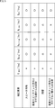
- each spatial transfer characteristic matrix held in the spatial transfer characteristic matrix generation unit 68 is a matrix capable of correcting each element shown in FIG.
- G ideal '(n tf ), G diag ' (n tf ), G tridiag '(n tf ), G block ' (n tf ), and G all '(n tf ) are respectively spatial transfer characteristics.
- correction factors for spatial correction processing include “speaker characteristics”, “reflection from a wall parallel to the linear speaker array direction”, “reverberation”, and “linear speaker array direction”. Reflection from non-parallel walls "is shown.
- peaker characteristic indicates the frequency characteristic of the linear speaker array 22 itself and the frequency characteristic of each speaker constituting the linear speaker array 22, and when this correction element is corrected, the frequency characteristic becomes flat. Become.
- “Reflection from a wall parallel to the direction of the linear speaker array” indicates a reflected sound from a wall having a surface parallel to the direction in which the speakers constituting the linear speaker array 22 are arranged in the reproduction space. Is corrected, it becomes difficult for the listener to hear such reflected sound.
- “Reverberation” indicates reverberation in the reproduction space.
- this correction factor is corrected, it becomes difficult for the listener to hear the reverberation sound generated in the reproduction space.
- “reflection from a wall not parallel to the linear speaker array direction” indicates a reflected sound from a wall having a surface that is not parallel to the direction in which the speakers constituting the linear speaker array 22 are arranged in the reproduction space.
- the element is corrected, it is difficult for the listener to hear such reflected sound.
- each column indicates the degree to which each correction element is corrected by the space correction process using each space transfer characteristic matrix. Specifically, “ ⁇ ” indicates that the correction element is sufficiently corrected, “ ⁇ ” indicates that the correction element is corrected to some extent, and “ ⁇ ” indicates that the correction element is hardly corrected. It is shown that.
- the amount of calculation during the spatial correction processing increases.
- the amount of computation during spatial correction processing is the smallest when the spatial transfer characteristic matrix G ideal '(n tf ) is used, and the largest when the spatial transfer characteristic matrix G all ' (n tf ) is used. .
- the spatial transfer characteristic matrix G ideal ′ (n tf ) shows the ideal spatial transfer characteristic, even if spatial correction processing is performed using this spatial transfer characteristic matrix G ideal ′ (n tf ), Specifically, no correction element is corrected. That is, when the spatial transfer characteristic matrix G ideal '(n tf ) is used, the amount of computation can be suppressed low, but high spatial reproducibility cannot be obtained.
- the spatial transfer characteristic matrix G diag '(n tf ), the spatial transfer characteristic matrix G tridiag ' (n tf ), the spatial transfer characteristic matrix G block '(n tf ), and the spatial transfer characteristic matrix G all ' (n tf ) Is obtained by extracting some or all of the elements of the spatial transfer characteristic matrix G measure '(n tf ).
- the inverse discrete Fourier transform matrix F and its Hermitian transpose matrix F H come closer to a matrix composed of eigenvectors, so that the energy of the spatial transfer characteristic matrix G measure '(n tf ) Concentrate on the diagonal component.
- the inverse discrete Fourier transform matrix F and its Hermitian transpose matrix F H are composed of eigenvectors of the matrix G measure (n tf ), “speaker characteristics”, “reflection from the wall parallel to the linear speaker array direction” , And components related to “reverberation” should be included in the diagonal components of the spatial transfer characteristic matrix G measure ′ (n tf ).
- a component related to reverberation in the reproduction space may appear in the inverse diagonal component of the spatial transfer characteristic matrix G measure ′ (n tf ). Therefore, in some cases, the reverberant sound may not be corrected sufficiently by the spatial transfer characteristic matrix G diag '(n tf ).
- the energy of the spatial transfer characteristic matrix G measure '(n tf ) leaks to the off-diagonal component.
- the spatial transfer characteristic matrix G tridiag '(n tf ) obtained by extracting only the tridiagonal component of the spatial transfer characteristic matrix G measure ' (n tf ) leaks to the non-diagonal component. To some extent.
- the spatial transfer characteristic matrix G block '(n tf ) obtained by extracting only a specific block of the spatial transfer characteristic matrix G measure ' (n tf ) includes the spatial transfer characteristic matrix G tridiag '( There should be more leaked components in non-diagonal components than n tf ).
- the spatial transfer processing matrix G all '(n tf ) is used to correct all the elements, and the highest Spatial reproducibility can be realized.
- the calculation amount of the spatial correction processing is between O (n) and O (n 2 ), and the calculation amount can be greatly reduced.
- the spatial correction method selection unit 67 selects the weight W sp related to the number of speakers constituting the linear speaker array 22 and the calculation capability of the receiver 12. That is, the spatial correction information flg is corrected based on the weight W power related to the total amount of computing resources. In other words, the spatial correction method selection unit 67 selects a spatial correction method based on the spatial correction information flg, the number of speakers of the linear speaker array 22, and the computing capability of the receiver 12.
- the spatial correction information flg supplied from the decoding unit 66 is stored in advance or multiplied by a weight W sp and a weight W power input by a user or the like, thereby obtaining a final result. Spatial correction information flg is obtained.
- the weight W sp is set to be smaller than 1 when the number of speakers constituting the linear speaker array 22 is relatively large, and to be larger than 1 when the number of speakers is small.
- the weight W power is set to be larger than 1 when the computing capability of the receiver 12 is relatively high, and is set to a value smaller than 1 when the computing capability is low.
- the space correction method selection unit 67 selects the space correction method by comparing the space correction information flg corrected as described above with some predetermined threshold values.
- the spatial transfer characteristic matrix G ideal '(n tf ), the spatial transfer characteristic matrix G diag ' (n tf ), the spatial transfer characteristic matrix G tridiag '(n tf ), and the spatial transfer characteristic A threshold ⁇ ideal , a threshold ⁇ diag , a threshold ⁇ tridiag , and a threshold ⁇ block are defined for the matrix G block ′ (n tf ).
- the spatial correction method selection unit 67 compares the spatial correction information flg with these threshold values ⁇ ideal to threshold value ⁇ block, and sets the threshold value having the smallest value among the threshold values larger than the spatial correction information flg.
- the corresponding spatial transfer characteristic matrix is selected as the spatial transfer characteristic matrix G ′ (n tf ).
- the spatial correction method selection unit 67 selects the spatial transfer characteristic matrix G all ′ (n tf ) as the spatial transfer characteristic matrix G ′ (n tf ). .
- the method for selecting the spatial transfer characteristic matrix G ′ (n tf ) is any other method such as selecting the spatial transfer characteristic matrix corresponding to the threshold value closest to the spatial correction information flg. May be.
- the drive signal generation unit 69 includes the spatial transfer characteristic matrix G ′ (n tf ) supplied from the spatial transfer characteristic matrix generation unit 68 and the spatial frequency spectrum S SP (n tf , n sf ) supplied from the decoding unit 66. Then, the following equation (10) is calculated to obtain the speaker drive signal D SP (n tf , n sf ) in the spatial frequency domain.
- the spatial correction process is a process for correcting the spatial transfer characteristic using the spatial transfer characteristic matrix G ′ (n tf ). That is, as the spatial transfer characteristic of the reproduction space used in the calculation of Expression (10) when calculating the speaker drive signal D SP (n tf , n sf ), the spatial transfer characteristic indicating the spatial transfer characteristic obtained from the actual measurement result By using the matrix G ′ (n tf ), the spatial transfer characteristic used in the calculation is corrected so as to be closer to the actual one. As a result, a speaker drive signal in which signal degradation during reproduction due to the spatial transfer characteristic of the actual reproduction space is corrected in advance, that is, the spatial transfer characteristic is corrected is calculated.
- G ′ + (n tf ) is a pseudo inverse matrix of the spatial transfer characteristic matrix G ′ (n tf ).
- J represents a pure imaginary number
- k x represents a spatial frequency in the x-axis direction
- ⁇ represents a time angular frequency
- c represents a sound velocity.
- Equation (10) y represents the distance between the linear microphone array 101 and the linear speaker array 22 in the y-axis direction.
- the spatial sampling rate of the spatial frequency spectrum S SP (n tf , n sf ) and the spatial transfer characteristic matrix G ′ (n tf ) are assumed to be equal here. However, if their spatial sampling rates are different, either the spatial frequency spectrum S SP (n tf , n sf ) or the spatial transfer characteristic matrix G ′ (n tf ) is aligned with the other spatial sampling rate, It is necessary to perform processing so that both of them have the same new spatial sampling rate.
- the number of spatial frequency spectrum samples of the spatial frequency spectrum S SP (n tf , n sf ) and the spatial transfer characteristic matrix G ′ (n tf ) are equal.
- the spatial frequency spectrum S SP (n tf , n sf ) or the spatial transfer characteristic matrix G ′ (n tf ) is aligned with the other sample number, or It is necessary to appropriately perform processing such as zero padding and high frequency removal so that both have the same new number of samples.
- the speaker drive signal may be calculated by other methods.
- SDM is described in detail in “Jens Adrens, Sascha Spors,“ Applying the Ambisonics Approach on Planar and Linear Arrays of Loudspeakers, ”in 2nd International Symposium on Ambisonics and Spherical Acoustics.”
- the drive signal generation unit 69 supplies the obtained speaker drive signal D SP (n tf , n sf ) to the spatial frequency synthesis unit 70.
- the spatial frequency synthesis unit 70 performs spatial frequency synthesis using DFT on the spatial frequency spectrum that is the speaker drive signal D SP (n tf , n sf ) supplied from the drive signal generation unit 69, and the temporal frequency spectrum D (l, n tf ) is obtained. That is, the calculation of the following equation (11) is performed, and the speaker drive signal D SP (n tf , n sf ) is synthesized with a spatial frequency.
- Equation (11) l indicates a speaker index that identifies the speakers constituting the linear speaker array 22, and M ds indicates the number of DFT samples.
- the spatial frequency synthesizer 70 supplies the temporal frequency spectrum D (l, ntf ) obtained by the spatial frequency synthesis to the temporal frequency synthesizer 71.
- the time frequency synthesizer 71 performs time frequency synthesis using IDFT on the time frequency spectrum D (l, n tf ) supplied from the spatial frequency synthesizer 70 by calculating the following equation (12):
- n d represents a time index
- M dt represents the number of IDFT samples.
- the time-frequency synthesizer 71 supplies the speaker drive signal d (l, n d ) thus obtained to each speaker constituting the linear speaker array 22 and reproduces sound.
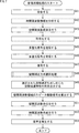
- the spatial correction controller 51 measures the spatial transfer characteristics using the linear speaker array 22 and the linear microphone array 101 in the reproduction space, for example, and the time signal g measure (l, m, n c ) obtained as a result is measured.
- the spatial transfer characteristic matrix generation unit 68 When supplied to the spatial transfer characteristic matrix generation unit 68, a spatial transfer characteristic matrix generation process is performed to generate a spatial transfer characteristic matrix used in each spatial correction method.
- step S11 the spatial transfer characteristic matrix generation unit 68 calculates a spatial transfer characteristic matrix G ideal ′ (n tf ) indicating ideal spatial transfer characteristics.
- G ideal ′ n tf
- the above-described equation (3) is calculated to calculate the spatial transfer characteristic matrix G ideal '(n tf ).
- step S12 the spatial transfer characteristic matrix generation unit 68 calculates the spatial transfer characteristic matrix G measure '(n tf ) based on the measurement result of the spatial transfer characteristic.
- the spatial transfer characteristic matrix generation unit 68 performs time-frequency conversion on the time signal g measure (l, m, n c ) that is the measurement result of the spatial transfer characteristic, and the time-frequency spectrum G measure (l , m, n tf ).
- the spatial transfer characteristic matrix generation unit 68 calculates the above-described formula (9) based on the obtained time-frequency spectrum G measure (l, m, n tf ), and the spatial transfer characteristic matrix G measure '(n tf ) is calculated.
- step S13 the spatial transfer characteristic matrix generator 68 generates a spatial transfer characteristic matrix G diag '(n tf ) based on the spatial transfer characteristic matrix G measure ' (n tf ).
- the spatial transfer characteristic matrix generation unit 68 extracts only the diagonal component of the spatial transfer characteristic matrix G measure '(n tf ) and sets it as the spatial transfer characteristic matrix G diag ' (n tf ).
- step S14 the spatial transfer characteristic matrix generator 68 'based on (n tf), space transfer characteristic matrix G tridiag' space transfer characteristic matrix G its measure to generate a (n tf).
- spatial transfer characteristic matrix generator 68 For example spatial transfer characteristic matrix generator 68, a space transfer characteristic matrix G measure '(n tf) of tridiagonal component only extracted and space transfer characteristic matrix G tridiag' (n tf).
- step S15 the spatial transfer characteristic matrix generation unit 68 generates a spatial transfer characteristic matrix G block ′ (n tf ) based on the spatial transfer characteristic matrix G measure ′ (n tf ).
- the spatial transfer characteristic matrix generation unit 68 extracts only a specific block of the spatial transfer characteristic matrix G measure '(n tf ) and sets it as the spatial transfer characteristic matrix G block ' (n tf ).
- step S16 the spatial transfer characteristic matrix generation unit 68 generates a spatial transfer characteristic matrix G all '(n tf ) based on the spatial transfer characteristic matrix G measure ' (n tf ).
- the spatial transfer characteristic matrix generation unit 68 sets the spatial transfer characteristic matrix G measure '(n tf ) itself as the spatial transfer characteristic matrix G all ' (n tf ).
- the spatial transfer characteristic matrix generation unit 68 includes a spatial transfer characteristic matrix G ideal '(n tf ), a spatial transfer characteristic matrix G diag ' (n tf ), a spatial transfer characteristic matrix G tridiag '(n tf ), and a spatial transfer characteristic matrix G block When '(n tf ) and the spatial transfer characteristic matrix G all ' (n tf ) are generated, these spatial transfer characteristic matrices are retained, and the spatial transfer characteristic matrix generation process ends.
- the space correction controller 51 generates and holds a plurality of space transfer characteristic matrices having different amounts of calculation during the space correction process based on the actually measured space transfer characteristics.
- the spatial correction controller 51 performs a sound field reproduction process for reproducing the sound field of the sound collection space in the reproduction space. Will be able to do.
- step S ⁇ b> 41 the linear microphone array 21 collects the sound of the content in the sound collection space, and supplies the multi-channel sound collection signal s (i, nt ) obtained as a result to the time frequency analysis unit 61.
- step S ⁇ b> 42 the time frequency analysis unit 61 analyzes time frequency information of the collected sound signal s (i, n t ) supplied from the linear microphone array 21.
- the time frequency analysis unit 61 performs time frequency conversion on the collected sound signal s (i, n t ) and supplies the resulting time frequency spectrum S (i, n tf ) to the spatial frequency analysis unit 62. To do. For example, in step S42, the calculation of the above-described equation (1) is performed.
- step S43 the spatial frequency analysis unit 62 performs spatial frequency conversion on the temporal frequency spectrum S (i, n tf ) supplied from the temporal frequency analysis unit 61, and the spatial frequency spectrum S SP ( n tf , n sf ) are supplied to the encoding unit 63.
- the above-described equation (2) is calculated.
- step S44 the encoding unit 63 encodes the spatial frequency spectrum S SP (n tf , n sf ) supplied from the spatial frequency analysis unit 62 and the spatial correction information flg input by the content producer or the like, The multiplexed signal obtained as a result is supplied to the communication unit 64.
- the spatial correction information flg stored in the multiplexed signal can be switched in arbitrary time units such as for each content or for each frame of the content.
- the encoding unit 63 acquires the spatial correction information flg at an appropriate timing when the switching is performed.
- step S45 the communication unit 64 transmits the multiplexed signal supplied from the encoding unit 63.
- step S46 the communication unit 65 receives the multiplexed signal transmitted by the communication unit 64 and supplies the multiplexed signal to the decoding unit 66.
- step S47 the decoding unit 66 decodes the multiplexed signal supplied from the communication unit 65, supplies the spatial correction information flg obtained as a result thereof to the spatial correction method selection unit 67, and obtains the space obtained by decoding.
- the frequency spectrum S SP (n tf , n sf ) is supplied to the drive signal generator 69.
- step S48 the spatial correction method selection unit 67 performs a spatial correction method selection process, selects a spatial correction method based on the spatial correction information flg supplied from the decoding unit 66, and displays the selection result as a spatial transfer characteristic. This is supplied to the matrix generation unit 68. Details of the spatial correction method selection processing will be described later.
- step S49 the spatial transfer characteristic matrix generation unit 68 generates a spatial transfer characteristic matrix corresponding to the selected spatial correction method based on the information indicating the selection result of the spatial correction method supplied from the spatial correction method selection unit 67. Output.
- the spatial transfer characteristic matrix generator 68 stores the spatial transfer characteristic matrix G ideal '(n tf ), the spatial transfer characteristic matrix G diag ' (n tf ), and the spatial transfer characteristic matrix G tridiag '(n tf ).
- the spatial transfer characteristic matrix G ′ (n tf ) is supplied to the drive signal generator 69.
- the spatial transfer characteristic matrix generation unit 68 may generate and output the spatial transfer characteristic matrix indicated by the selection result after the spatial correction method selection result is supplied from the spatial correction method selection unit 67. Good.
- step S50 the drive signal generation unit 69 and the spatial transfer characteristic matrix G ′ (n tf ) supplied from the spatial transfer characteristic matrix generation unit 68 and the spatial frequency spectrum S SP (n tf , supplied from the decoding unit 66). n sf ), the speaker drive signal D SP (n tf , n sf ) in the spatial frequency domain is calculated.
- the drive signal generation unit 69 calculates the above-described equation (10) to calculate the speaker drive signal D SP (n tf , n sf ) and supplies it to the spatial frequency synthesis unit 70.
- step S51 the spatial frequency synthesis unit 70 performs spatial frequency synthesis on the speaker drive signal D SP (n tf , n sf ) supplied from the drive signal generation unit 69, and the time frequency spectrum D obtained as a result thereof. (l, n tf ) is supplied to the time-frequency synthesis unit 71.
- the above equation (11) is calculated.
- step S52 the time-frequency synthesizer 71 performs time-frequency synthesis on the time-frequency spectrum D (l, n tf ) supplied from the spatial frequency synthesizer 70, and the resulting speaker drive signal d (l , n d ) are supplied to the linear speaker array 22.
- the above equation (12) is calculated.
- step S ⁇ b > 53 the linear speaker array 22 reproduces sound based on the speaker drive signal d (l, n d ) supplied from the time frequency synthesis unit 71. Thereby, the content, that is, the sound field of the sound collection space is reproduced.
- the spatial correction controller 51 selects a spatial correction method for correcting the spatial transfer characteristic based on the spatial correction information flg, and performs a spatial correction process according to the selection result. Thereby, a sound field can be reproduced more appropriately according to the content.
- the spatial correction method is selected based on the spatial correction information flg
- the calculation resource of the receiver 12 is set according to the reproduction environment such as the content itself, the calculation capability of the receiver 12, and the number of speakers of the linear speaker array 22.
- it can be appropriately assigned to the spatial correction processing and other processing such as sound quality improvement processing.
- sound quality improvement processing As a result, it is possible to achieve optimal sound field reproduction, such as emphasizing spatial reproducibility or emphasizing sound quality reproducibility.
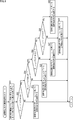
- step S ⁇ b> 81 the spatial correction method selection unit 67 multiplies the spatial correction information flg supplied from the decoding unit 66 by the weight W sp related to the number of speakers and the weight W power related to the computing ability to obtain the spatial correction information flg. to correct.
- step S82 the spatial correction method selection unit 67 compares the spatial correction information flg corrected in the process of step S81 with the threshold value ⁇ ideal to determine whether or not threshold value ⁇ ideal ⁇ spatial correction information flg. It is determined whether or not the spatial correction information flg is larger than a threshold value ⁇ ideal .
- step S82 If it is determined in step S82 that the threshold ⁇ ideal ⁇ the spatial correction information flg is not satisfied, that is, the spatial correction information flg is equal to or smaller than the threshold ⁇ ideal , the process proceeds to step S83.
- step S83 the spatial correction method selection unit 67 selects a spatial correction method that uses the spatial transfer characteristic matrix G ideal '(n tf ) for the spatial correction processing.
- the spatial correction method selection unit 67 selects the spatial transfer characteristic matrix G ideal ′ (n tf ) as the spatial transfer characteristic matrix G ′ (n tf ), and sends information indicating the selection result to the spatial transfer characteristic matrix generation unit 68. Supply.
- the spatial correction method selection process ends, and then the process proceeds to step S49 in FIG.
- the spatial correction method selection unit 67 selects a spatial correction method with the smallest amount of calculation so that calculation resources are allocated to other processes.
- the spatial correction information flg is corrected by the weight W sp regarding number of speakers. Therefore, for example, when the number of speakers is large and the energy of the spatial transfer characteristic matrix G measure '(n tf ) is concentrated on the diagonal component, a sufficiently high spatial reproducibility can be obtained even with a small amount of spatial correction processing. Therefore, the spatial correction information flg is corrected to be small. Thereby, sufficient space reproducibility can be obtained with a smaller amount of computation, and more appropriate sound field reproduction can be realized.
- the spatial correction method selection unit 67 corrects the spatial correction information flg with the weight W power related to the computing ability. Therefore, for example, when the calculation capability of the receiver 12 is high and sufficient calculation resources can be allocated for the spatial correction process, the correction is performed so that the spatial correction information flg becomes large. As a result, it is possible to secure sufficient computing resources for the correction space processing and realize more appropriate sound field reproduction.
- step S82 If it is determined in step S82 that the threshold ⁇ ideal ⁇ spatial correction information flg, that is, the spatial correction information flg is greater than the threshold ⁇ ideal , the process proceeds to step S84.
- step S84 the spatial correction method selection unit 67 compares the spatial correction information flg corrected in the process of step S81 with the threshold value ⁇ diag to determine whether or not threshold value ⁇ diag ⁇ spatial correction information flg. It is determined whether or not the spatial correction information flg is larger than the threshold value ⁇ diag .
- step S84 If it is determined in step S84 that the threshold ⁇ diag is not smaller than the spatial correction information flg, that is, the spatial correction information flg is equal to or smaller than the threshold ⁇ diag , the process proceeds to step S85.
- step S85 the spatial correction method selection unit 67 selects a spatial correction method that uses the spatial transfer characteristic matrix G diag '(n tf ) for the spatial correction processing.
- the spatial correction method selection unit 67 selects the spatial transfer characteristic matrix G diag '(n tf ) as the spatial transfer characteristic matrix G ′ (n tf ), and sends information indicating the selection result to the spatial transfer characteristic matrix generation unit 68. Supply.
- the spatial correction method selection process ends, and then the process proceeds to step S49 in FIG.
- step S84 If it is determined in step S84 that the threshold ⁇ diag ⁇ spatial correction information flg, that is, the spatial correction information flg is greater than the threshold ⁇ diag , the process proceeds to step S86.
- step S86 the spatial correction method selection unit 67 compares the spatial correction information flg corrected in the process of step S81 with the threshold ⁇ tridiag to determine whether or not threshold ⁇ tridiag ⁇ spatial correction information flg. It is determined whether or not the spatial correction information flg is larger than a threshold value ⁇ tridiag .
- step S86 If it is determined in step S86 that the threshold ⁇ tridiag is not smaller than the spatial correction information flg, that is, the spatial correction information flg is equal to or smaller than the threshold ⁇ tridiag , the process proceeds to step S87.
- step S87 the spatial correction method selection unit 67 selects a spatial correction method that uses the spatial transfer characteristic matrix G tridiag '(n tf ) for the spatial correction processing.
- the spatial correction method selection unit 67 selects the spatial transfer characteristic matrix G tridiag ′ (n tf ) as the spatial transfer characteristic matrix G ′ (n tf ), and sends information indicating the selection result to the spatial transfer characteristic matrix generation unit 68. Supply.
- the spatial correction method selection process ends, and then the process proceeds to step S49 in FIG.
- step S86 determines whether the threshold ⁇ tridiag ⁇ spatial correction information flg, that is, the spatial correction information flg is greater than the threshold ⁇ tridiag . If it is determined in step S86 that the threshold ⁇ tridiag ⁇ spatial correction information flg, that is, the spatial correction information flg is greater than the threshold ⁇ tridiag , the process proceeds to step S88.
- step S88 the spatial correction method selection unit 67 compares the spatial correction information flg corrected in the process of step S81 with the threshold ⁇ block to determine whether or not threshold ⁇ block ⁇ spatial correction information flg. It is determined whether or not the spatial correction information flg is larger than the threshold ⁇ block .
- step S88 If it is determined in step S88 that the threshold ⁇ block ⁇ the spatial correction information flg is not satisfied, that is, the spatial correction information flg is equal to or smaller than the threshold ⁇ block , the process proceeds to step S89.
- step S89 the spatial correction method selection unit 67 selects a spatial correction method that uses the spatial transfer characteristic matrix G block ′ (n tf ) for the spatial correction processing.
- the spatial correction method selection unit 67 selects the spatial transfer characteristic matrix G block ′ (n tf ) as the spatial transfer characteristic matrix G ′ (n tf ), and sends information indicating the selection result to the spatial transfer characteristic matrix generation unit 68. Supply.
- the spatial correction method selection process ends, and then the process proceeds to step S49 in FIG.
- step S88 if it is determined in step S88 that the threshold ⁇ block ⁇ spatial correction information flg, that is, the spatial correction information flg is greater than the threshold ⁇ block , the process proceeds to step S90.
- step S90 the spatial correction method selection unit 67 selects a spatial correction method that uses the spatial transfer characteristic matrix G all '(n tf ) for the spatial correction processing.
- the spatial correction method selection unit 67 selects the spatial transfer characteristic matrix G all ′ (n tf ) as the spatial transfer characteristic matrix G ′ (n tf ), and sends information indicating the selection result to the spatial transfer characteristic matrix generation unit 68. Supply.
- the spatial correction method selection process ends, and then the process proceeds to step S49 in FIG.
- the spatial correction controller 51 appropriately corrects the spatial correction information flg and compares the corrected spatial correction information flg with a predetermined threshold value to select a spatial correction method. As a result, it is possible to perform an optimal spatial correction process in consideration of the intention of the content producer, the content reproduction environment, the computing capability of the receiver 12, and the like. As a result, optimal sound field reproduction can be realized.
- the series of processes described above can be executed by hardware or can be executed by software.
- a program constituting the software is installed in the computer.
- the computer includes, for example, a general-purpose computer capable of executing various functions by installing a computer incorporated in dedicated hardware and various programs.
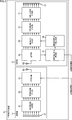
- FIG. 9 is a block diagram showing an example of the hardware configuration of a computer that executes the above-described series of processing by a program.
- a CPU Central Processing Unit
- ROM Read Only Memory
- RAM Random Access Memory
- An input / output interface 505 is further connected to the bus 504.
- An input unit 506, an output unit 507, a recording unit 508, a communication unit 509, and a drive 510 are connected to the input / output interface 505.
- the input unit 506 includes a keyboard, a mouse, a microphone, an image sensor, and the like.
- the output unit 507 includes a display, a speaker, and the like.
- the recording unit 508 includes a hard disk, a nonvolatile memory, and the like.
- the communication unit 509 includes a network interface or the like.
- the drive 510 drives a removable medium 511 such as a magnetic disk, an optical disk, a magneto-optical disk, or a semiconductor memory.
- the CPU 501 loads the program recorded in the recording unit 508 to the RAM 503 via the input / output interface 505 and the bus 504 and executes the program, for example. Is performed.
- the program executed by the computer (CPU 501) can be provided by being recorded in, for example, a removable medium 511 as a package medium or the like.
- the program can be provided via a wired or wireless transmission medium such as a local area network, the Internet, or digital satellite broadcasting.
- the program can be installed in the recording unit 508 via the input / output interface 505 by attaching the removable medium 511 to the drive 510. Further, the program can be received by the communication unit 509 via a wired or wireless transmission medium and installed in the recording unit 508. In addition, the program can be installed in advance in the ROM 502 or the recording unit 508.
- the program executed by the computer may be a program that is processed in time series in the order described in this specification, or in parallel or at a necessary timing such as when a call is made. It may be a program for processing.
- the present technology can take a cloud computing configuration in which one function is shared by a plurality of devices via a network and is jointly processed.
- each step described in the above flowchart can be executed by one device or can be shared by a plurality of devices.
- the plurality of processes included in the one step can be executed by being shared by a plurality of apparatuses in addition to being executed by one apparatus.
- the present technology can be configured as follows.
- the space correction method selection unit selects the space correction method based on the space correction information and the number of speakers constituting a speaker array that outputs sound based on the sound signal.
- a signal processing device 1.
- the signal processing device selects the spatial correction method based on the spatial correction information and the calculation capability of the signal processing device. .
- the spatial transfer characteristic matrix is obtained by extracting a part or all of a matrix indicating a spatial transfer characteristic of a space in which sound based on the audio signal is reproduced (1) to (5) The signal processing device according to one item.
- the spatial transfer characteristic matrix of the plurality of spatial correction methods is obtained by extracting only the spatial transfer characteristic matrix obtained by extracting at least the diagonal component of the matrix and only the tridiagonal component of the matrix.
- At least one of the obtained spatial transfer characteristic matrix, the spatial transfer characteristic matrix obtained by extracting only a specific block of the matrix, and the spatial transfer characteristic matrix that is the matrix (6) The signal processing apparatus as described.
- the acquisition unit acquires the spatial correction information together with the audio signal.
- one spatial correction method is selected from a plurality of spatial correction methods for correcting the spatial transfer characteristics, A signal processing method including a step of performing a spatial correction process on the audio signal based on the selected spatial transfer characteristic matrix of the spatial correction method.
- one spatial correction method is selected from a plurality of spatial correction methods for correcting the spatial transfer characteristics, A program for causing a computer to execute a process including a step of performing a spatial correction process on the audio signal based on a selected spatial transfer characteristic matrix of the spatial correction method.
- a signal processing apparatus comprising: an output unit that outputs the audio signal and the spatial correction information.
- the spatial correction information is information indicating a priority of the spatial correction processing.
- the spatial correction information is determined in a predetermined time unit with respect to the audio signal.
Landscapes
- Physics & Mathematics (AREA)
- Engineering & Computer Science (AREA)
- Acoustics & Sound (AREA)
- Signal Processing (AREA)
- Multimedia (AREA)
- Health & Medical Sciences (AREA)
- Otolaryngology (AREA)
- Audiology, Speech & Language Pathology (AREA)
- General Health & Medical Sciences (AREA)
- Circuit For Audible Band Transducer (AREA)
Abstract
La présente invention concerne un programme, ainsi qu'un dispositif et un procédé de traitement de signal, avec lesquels il est possible de reproduire de manière plus appropriée un champ sonore conformément à son contenu. Une unité de décodage décode un signal multiplexé afin d'obtenir un signal de capture sonore à multiples canaux en captant un son à l'aide d'un réseau de microphones linéaire, puis d'obtenir des informations de réglage spatial pour sélectionner un processus de réglage spatial afin d'ajuster des caractéristiques de transmission spatiale. Une unité de sélection de processus de réglage spatial sélectionne le processus de réglage spatial sur la base des informations de réglage spatial, puis une unité de production de matrice de caractéristique de transmission spatiale délivre une matrice de caractéristique de transmission spatiale, de la manière indiquée par le résultat de sélection de processus de réglage spatial. Une unité de production de signal d'entraînement produit un signal d'entraînement de haut-parleur de domaine de fréquence spatial sur la base du signal de capture sonore à multiples canaux et de la matrice de caractéristique de transmission spatiale. La présente invention peut être appliquée à des organes de commande de réglage spatial.
Priority Applications (1)
| Application Number | Priority Date | Filing Date | Title |
|---|---|---|---|
| US15/564,518 US10380991B2 (en) | 2015-04-13 | 2016-04-01 | Signal processing device, signal processing method, and program for selectable spatial correction of multichannel audio signal |
Applications Claiming Priority (2)
| Application Number | Priority Date | Filing Date | Title |
|---|---|---|---|
| JP2015081608 | 2015-04-13 | ||
| JP2015-081608 | 2015-04-13 |
Publications (1)
| Publication Number | Publication Date |
|---|---|
| WO2016167138A1 true WO2016167138A1 (fr) | 2016-10-20 |
Family
ID=57126142
Family Applications (1)
| Application Number | Title | Priority Date | Filing Date |
|---|---|---|---|
| PCT/JP2016/060895 WO2016167138A1 (fr) | 2015-04-13 | 2016-04-01 | Programme, dispositif et procédé de traitement de signal |
Country Status (2)
| Country | Link |
|---|---|
| US (1) | US10380991B2 (fr) |
| WO (1) | WO2016167138A1 (fr) |
Families Citing this family (6)
| Publication number | Priority date | Publication date | Assignee | Title |
|---|---|---|---|---|
| CN106165444B (zh) | 2014-04-16 | 2019-09-17 | 索尼公司 | 声场再现设备、方法和程序 |
| EP3346728A4 (fr) | 2015-09-03 | 2019-04-24 | Sony Corporation | Dispositif et procédé de traitement de son, et programme |
| JP6841229B2 (ja) | 2015-12-10 | 2021-03-10 | ソニー株式会社 | 音声処理装置および方法、並びにプログラム |
| WO2018042791A1 (fr) | 2016-09-01 | 2018-03-08 | ソニー株式会社 | Dispositif de traitement d'informations, procédé de traitement d'informations, et support d'enregistrement dispositif de traitement d'informations, procédé de traitement d'informations et support d'enregistrement |
| NL2018617B1 (en) * | 2017-03-30 | 2018-10-10 | Axign B V | Intra ear canal hearing aid |
| CN111210837B (zh) * | 2018-11-02 | 2022-12-06 | 北京微播视界科技有限公司 | 音频处理方法和装置 |
Citations (3)
| Publication number | Priority date | Publication date | Assignee | Title |
|---|---|---|---|---|
| JPH02503721A (ja) * | 1988-03-24 | 1990-11-01 | バーチ・ウッド・アクースティックス・ネーデルランド・ビー・ヴィー | 電気音響システム |
| JP2010062700A (ja) * | 2008-09-02 | 2010-03-18 | Yamaha Corp | 音場伝送システムおよび音場伝送方法 |
| JP2010193323A (ja) * | 2009-02-19 | 2010-09-02 | Casio Hitachi Mobile Communications Co Ltd | 録音装置、再生装置、録音方法、再生方法、及びコンピュータプログラム |
Family Cites Families (6)
| Publication number | Priority date | Publication date | Assignee | Title |
|---|---|---|---|---|
| EP1984913A4 (fr) * | 2006-02-07 | 2011-01-12 | Lg Electronics Inc | Appareil et procédé de codage/décodage de signal |
| US8770881B2 (en) * | 2009-06-23 | 2014-07-08 | Cleanint Llc | Sanitization apparatuses, kits, and methods |
| JP5330136B2 (ja) * | 2009-07-22 | 2013-10-30 | 株式会社東芝 | 半導体記憶装置 |
| US9036843B2 (en) * | 2010-02-05 | 2015-05-19 | 2236008 Ontario, Inc. | Enhanced spatialization system |
| EP2884489B1 (fr) * | 2013-12-16 | 2020-02-05 | Harman Becker Automotive Systems GmbH | Système acoustique comprenant un synthétiseur de son moteur |
| US9508335B2 (en) * | 2014-12-05 | 2016-11-29 | Stages Pcs, Llc | Active noise control and customized audio system |
-
2016
- 2016-04-01 WO PCT/JP2016/060895 patent/WO2016167138A1/fr active Application Filing
- 2016-04-01 US US15/564,518 patent/US10380991B2/en active Active
Patent Citations (3)
| Publication number | Priority date | Publication date | Assignee | Title |
|---|---|---|---|---|
| JPH02503721A (ja) * | 1988-03-24 | 1990-11-01 | バーチ・ウッド・アクースティックス・ネーデルランド・ビー・ヴィー | 電気音響システム |
| JP2010062700A (ja) * | 2008-09-02 | 2010-03-18 | Yamaha Corp | 音場伝送システムおよび音場伝送方法 |
| JP2010193323A (ja) * | 2009-02-19 | 2010-09-02 | Casio Hitachi Mobile Communications Co Ltd | 録音装置、再生装置、録音方法、再生方法、及びコンピュータプログラム |
Also Published As
| Publication number | Publication date |
|---|---|
| US10380991B2 (en) | 2019-08-13 |
| US20180075837A1 (en) | 2018-03-15 |
Similar Documents
| Publication | Publication Date | Title |
|---|---|---|
| WO2016167138A1 (fr) | Programme, dispositif et procédé de traitement de signal | |
| US10382849B2 (en) | Spatial audio processing apparatus | |
| US10674262B2 (en) | Merging audio signals with spatial metadata | |
| US11671781B2 (en) | Spatial audio signal format generation from a microphone array using adaptive capture | |
| TWI631553B (zh) | 將以<i>L</i><sub>1</sub>個頻道為基礎之輸入聲音訊號產生至<i>L</i><sub>2</sub>個揚聲器頻道之方法及裝置,以及得到一能量保留混音矩陣之方法及裝置,用以將以輸入頻道為基礎之聲音訊號混音以用於<i>L</i><sub>1</sub>個聲音頻道至<i>L</i><sub>2</sub>個揚聲器頻道 | |
| US11832080B2 (en) | Spatial audio parameters and associated spatial audio playback | |
| KR20160086831A (ko) | 음장 재현 장치 및 방법, 그리고 프로그램 | |
| CN101009952A (zh) | 基于扬声器和听者的位置的有源音频矩阵解码方法和装置 | |
| JP6508539B2 (ja) | 音場収音装置および方法、音場再生装置および方法、並びにプログラム | |
| CN112567765B (zh) | 空间音频捕获、传输和再现 | |
| KR100763919B1 (ko) | 멀티채널 신호를 모노 또는 스테레오 신호로 압축한 입력신호를 2 채널의 바이노럴 신호로 복호화하는 방법 및 장치 | |
| US10986456B2 (en) | Spatial relation coding using virtual higher order ambisonic coefficients | |
| CN113574596A (zh) | 音频信号编码方法、音频信号解码方法、程序、编码装置、音频系统及解码装置 | |
| US20230254655A1 (en) | Signal processing apparatus and method, and program | |
| CN113766396A (zh) | 扬声器控制 | |
| JP2023500631A (ja) | 方向メタデータを使用するマルチチャネルオーディオ符号化及び復号化 | |
| CN116547749A (zh) | 音频参数的量化 | |
| EP3987513B1 (fr) | Quantification de composantes spatiales sur la base d'attributions de bits déterminées pour un codage audio psychoacoustique | |
| KR20110103094A (ko) | 멀티 채널 오디오 디코딩 방법 및 멀티 채널 오디오 코덱 | |
| JP2011002574A (ja) | 3次元音響符号化装置、3次元音響復号装置、符号化プログラム及び復号プログラム | |
| JP2017143325A (ja) | 収音装置、収音方法、プログラム |
Legal Events
| Date | Code | Title | Description |
|---|---|---|---|
| 121 | Ep: the epo has been informed by wipo that ep was designated in this application |
Ref document number: 16779929 Country of ref document: EP Kind code of ref document: A1 |
|
| WWE | Wipo information: entry into national phase |
Ref document number: 15564518 Country of ref document: US |
|
| NENP | Non-entry into the national phase |
Ref country code: DE |
|
| 122 | Ep: pct application non-entry in european phase |
Ref document number: 16779929 Country of ref document: EP Kind code of ref document: A1 |
|
| NENP | Non-entry into the national phase |
Ref country code: JP |