WO2016166804A1 - 照明装置及び光学部材 - Google Patents
照明装置及び光学部材 Download PDFInfo
- Publication number
- WO2016166804A1 WO2016166804A1 PCT/JP2015/061401 JP2015061401W WO2016166804A1 WO 2016166804 A1 WO2016166804 A1 WO 2016166804A1 JP 2015061401 W JP2015061401 W JP 2015061401W WO 2016166804 A1 WO2016166804 A1 WO 2016166804A1
- Authority
- WO
- WIPO (PCT)
- Prior art keywords
- cover
- light
- outer cover
- inner cover
- optical member
- Prior art date
- Legal status (The legal status is an assumption and is not a legal conclusion. Google has not performed a legal analysis and makes no representation as to the accuracy of the status listed.)
- Ceased
Links
Images





Classifications
-
- F—MECHANICAL ENGINEERING; LIGHTING; HEATING; WEAPONS; BLASTING
- F21—LIGHTING
- F21V—FUNCTIONAL FEATURES OR DETAILS OF LIGHTING DEVICES OR SYSTEMS THEREOF; STRUCTURAL COMBINATIONS OF LIGHTING DEVICES WITH OTHER ARTICLES, NOT OTHERWISE PROVIDED FOR
- F21V3/00—Globes; Bowls; Cover glasses
- F21V3/02—Globes; Bowls; Cover glasses characterised by the shape
-
- F—MECHANICAL ENGINEERING; LIGHTING; HEATING; WEAPONS; BLASTING
- F21—LIGHTING
- F21S—NON-PORTABLE LIGHTING DEVICES; SYSTEMS THEREOF; VEHICLE LIGHTING DEVICES SPECIALLY ADAPTED FOR VEHICLE EXTERIORS
- F21S6/00—Lighting devices intended to be free-standing
-
- F—MECHANICAL ENGINEERING; LIGHTING; HEATING; WEAPONS; BLASTING
- F21—LIGHTING
- F21V—FUNCTIONAL FEATURES OR DETAILS OF LIGHTING DEVICES OR SYSTEMS THEREOF; STRUCTURAL COMBINATIONS OF LIGHTING DEVICES WITH OTHER ARTICLES, NOT OTHERWISE PROVIDED FOR
- F21V3/00—Globes; Bowls; Cover glasses
-
- F—MECHANICAL ENGINEERING; LIGHTING; HEATING; WEAPONS; BLASTING
- F21—LIGHTING
- F21W—INDEXING SCHEME ASSOCIATED WITH SUBCLASSES F21K, F21L, F21S and F21V, RELATING TO USES OR APPLICATIONS OF LIGHTING DEVICES OR SYSTEMS
- F21W2121/00—Use or application of lighting devices or systems for decorative purposes, not provided for in codes F21W2102/00 – F21W2107/00
-
- F—MECHANICAL ENGINEERING; LIGHTING; HEATING; WEAPONS; BLASTING
- F21—LIGHTING
- F21Y—INDEXING SCHEME ASSOCIATED WITH SUBCLASSES F21K, F21L, F21S and F21V, RELATING TO THE FORM OR THE KIND OF THE LIGHT SOURCES OR OF THE COLOUR OF THE LIGHT EMITTED
- F21Y2115/00—Light-generating elements of semiconductor light sources
- F21Y2115/10—Light-emitting diodes [LED]
Definitions
- the present invention relates to an illuminating device having a light distribution characteristic such as a candle flame, and more particularly to an illuminating device including a light source with high directivity and an optical member for making light with high directivity look like a candle flame. .
- Patent Document 1 discloses that an optical member formed in an outer diameter shape simulating a candle flame is disposed on the LED, so that the light emitted from the LED can be brought into a light emission state simulating a candle flame.
- Patent Document 2 discloses a lighting lamp in which a light diffusing cover and a light diffusing lamp case are arranged in a double manner at regular intervals, centering on LEDs.
- Patent Document 3 is not a lighting device for obtaining a light distribution characteristic such as a candle flame, but in order to ensure the flame retardancy and safety of the LED lighting device and to control the light distribution,
- a double structure of the first optical cover and the outer second optical cover it is disclosed that either one is made of a material having excellent flame retardancy and the other is made of a material having excellent safety. Has been.
- Patent Document 1 in order to resemble a flame of a candle, it is necessary that an optical member molded in an outer diameter shape imitating a flame be subjected to a scattering process in which light is scattered in a region near the apex.
- the scattering treatment include a rough surface treatment and a satin treatment for forming irregularities on the surface, and a treatment for including a scattering material having a light scattering effect in the optical member 5.
- the optical member of Patent Document 1 needs to be subjected to scattering treatment and needs to change the scattering coefficient from the bottom to the top of the optical member, a simpler manufacturing method has been demanded.
- the lamp described in Patent Document 2 is simply sandblasted to the entire light diffusion cover. Even if the light diffused by the light diffusion cover is diffused by the light diffusion lamp case, the flame of the candle is lost. It was very different from the light emission state.
- An object of the present invention is to provide an illumination device that exhibits light distribution characteristics like a candle flame by light from a light source with high directivity. Another object of the present invention is to provide an optical member that converts light having high directivity into light distribution characteristics such as a candle flame. Furthermore, an object of the present invention is to provide an illumination device or an optical member that can be manufactured more easily than before and can be manufactured at low cost.
- a lighting device includes a light source that emits highly directional light, and one or more light-transmitting inner covers that are disposed so that light from the light source passes therethrough.
- a translucent and hollow outer cover that covers the outer side of the inner cover, and a tip outer shape of the inner cover disposed inside one of the outer covers is a tapered shape toward the top,
- the outer cover extends from the top of the inner cover arranged on the inner side to the top of the outer cover than the inner dimension of the cross section perpendicular to the optical axis at the position of the top of the inner cover arranged on the inner side.
- the length of is characterized by being longer.
- the optical member of the present invention has one or a plurality of translucent inner covers, and a translucent and hollow outer cover that covers the outside of the inner cover.
- the tip outer shape of the arranged inner cover is tapered toward the top, and the outer cover is based on the inner dimension of the cross section perpendicular to the optical axis at the position of the top of the inner cover arranged on the one inner side. Also, the length from the top of the inner cover disposed on the inner side to the top of the outer cover is longer.
- each surface of the inner surface of the outer cover may have the one surface in a region closer to the top of the outer cover than the position of the top of the inner cover disposed on the inner side.
- the radius of curvature at the arbitrary point is longer than the length from the top of the inner cover arranged on the inner side to any point on the inner surface of the outer cover (excluding the boundary of each surface). Is preferred.
- the one or more inner covers have a haze value equal to or higher than a haze value of the outer cover.
- the inner cover disposed on the one inner side is hollow inside, and the thickness from the inner surface to the outer surface is thicker at the top than at the bottom.
- the outer shape of the inner cover disposed on the one inner side may be a shape simulating a candle flame.
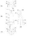
- FIGS. 5A to 5D are diagrams showing inner members of the optical member of Example 3.
- FIGS. 9A to 9D are diagrams showing an outer member of the optical member of Example 3.
- FIGS. (A) to (D) are illumination devices using the optical member of Example 3.
- the optical member of the present invention has one or a plurality of translucent inner covers and a translucent and hollow outer cover that covers the outside of the inner cover.
- a high-luminance inner flame region existing near the center of the candle flame is created by the inner cover, and the high-luminance
- the outer flame area of light brightness spreading around the high brightness area is overlaid, and the visual effect illumination close to that of the candle flame Can be provided.
- the number of the inner cover of the present invention may be one, or a plurality of inner covers may be stacked (see FIG. 2C).
- the inner cover adopts a tapered shape where the tip outer shape tapers toward the top, the light from the light source concentrates on the tip, and the tip part has a wide radiation angle The light was irradiated.
- the tip outer shape include a cone shape, a pyramid shape, and a semi-spindle shape.
- the entire inner cover may be conical, pyramidal, or semi-spindle, but it has a conical, pyramidal, or semi-spindle shape on the top side, and has a constant width on the bottom side. It is also possible to provide a region in which the width once widened is slightly narrowed on the bottom side so that the outer shape of the entire inner cover is similar to that of a candle flame.
- the inner cover of the present invention may be filled inside, but it is preferable to make the inside hollow in terms of cost and weight reduction. Furthermore, by making the interior hollow, light is reflected and refracted not only on the outer surface of the inner cover but also on the inner surface, so that a more complex light distribution state can be achieved, and in a high-intensity internal flame region You can also get closer.
- the inside it is preferable to increase the thickness from the inner surface to the outer surface of the inner cover at the top compared to the bottom, thereby concentrating light from the light source more at the tip to achieve high brightness.
- the outer cover of the present invention is hollow so that the inner cover is arranged inside, and the inner dimension of the cross section perpendicular to the optical axis at the top position of the inner cover arranged on the inner side (in FIG.
- the length from the top of the inner cover to the top of the outer cover (the length of A in FIG. 1) is longer than the length).
- Such a structure means that the outer cover is vertically long with respect to the front end of the inner cover, so that most of the light from the front end of the inner cover is incident on the outer cover at an angle, and enters the front end of the inner cover. Concentrated light is easily reflected by Fresnel.
- the outer surface and the inner surface of the outer cover of the present invention adopt a shape whose tip is narrowed toward the top, for example, a conical shape, a pyramid shape, or a semi-spindle shape.
- each surface of the inner surface of the outer cover is located outside from the top of the inner cover in a region on the top side of the outer cover (region A in FIG. 1) with respect to the position of the top of the inner cover arranged inside one. It is preferable that the radius of curvature at an arbitrary point on each surface is longer than the length to an arbitrary point on each surface of the inner surface of the cover (excluding the boundary between the surfaces).
- the inner surface of the outer cover makes it easy to reflect light emitted upward from the tip of the inner cover toward the viewer, and can increase the effect as an outer edge region. it can.
- the above conditions do not include the boundaries where the inner surfaces collide (for example, the boundary between the cylindrical portion and the cone portion, the apex of the tip).
- the vertex located at the tip of the inner surface is excluded from the above conditions.
- the boundary between the cylindrical portion and the conical portion is constituted by a smooth curved surface, it is compared with the curvature radius of such a phase.
- the radius of curvature is infinite. Therefore, it becomes longer than the length from the top of the inner cover to any point on the inner surface of the outer cover (excluding the vertex of the inner surface).
- the haze value (cloudiness) of the inner cover is preferably the same as or higher than that of the outer cover.
- a scattering agent may be mixed in the material of the inner cover, another material may be used, or after molding the inner cover using the same material, the surface may be sanded or sandblasted You may roughen.
- the inner cover has a light transmission performance that allows the hollow portion (inside the inner cover) to be visually recognized by adjusting the haze value and the thickness of the inner cover.
- the outer cover preferably has a light transmission performance that allows the inner cover to be visually recognized, and preferably has no scattering performance or is equal to or less than the haze value of the inner cover.
- the inner cover and the outer cover do not have to be completely transparent as long as the materials have translucency.
- the material may be plastic or glass, but is preferably plastic from the viewpoint of ease of molding, cost, and weight reduction.
- the plastic for example, PMMA (polymethyl methacrylate), PC (polycarbonate) or the like can be used.
- a scattering agent may be mixed into these materials, or a dye may be mixed or colored by coating.
- the inner cover and the outer cover have a relatively simple shape and can be mass-produced by injection molding.
- the inner cover and the outer cover may be configured separately as shown in FIGS. 1 and 2, but when manufactured from the same material, the inner cover and the outer cover may be integrally formed. For example, you may connect a part of outer periphery of the bottom part of an inner cover, and a part of inner periphery of the bottom part of an outer cover.
- the illuminating device of the present invention includes a light source that emits light with high directivity and the optical member as described above, and has a top portion with an optical axis centered from the bottom of the innermost inner cover of the optical member.
- Light with high directivity is emitted toward Between the light source and the optical member, the traveling direction of the light may be changed by a mirror, a prism, an optical fiber, etc., or it is divided into a plurality of lights by a beam splitter or the like, and the optical member is arranged for each light. You may do it.
- an LED light source can be used as the light source, but it is only necessary to irradiate light with high directivity other than the LED light source.
- FIG. 1 shows a cross-sectional shape along the optical axis of an embodiment of the optical member of the present invention.
- the optical member 1 shown in FIG. 1 has one inner cover 11 with an upwardly sharpened tip, and an outer cover 21 with an upwardly sharpened tip disposed outside the inner cover 11 so as to cover the inner cover 11. And.
- the inner cover 11 and the outer cover 21 are arranged so that the center is the optical axis.
- the light source is not shown, but the optical member 1 is arranged so that light having high directivity is irradiated from below to above with the optical axis c as the center.
- the inner cover 11 in FIG. 1 is hollow inside, has a top 12 at the tip, has a bottom 13 at the bottom, and has a circular cross-sectional shape perpendicular to the optical axis of the bottom 13.
- the inner cover 11 first extends vertically from the bottom 13 with a substantially uniform thickness and has a cylindrical shape, but then gradually becomes a semi-spindle shape toward the top 12.
- the spindle-shaped portion is configured such that the curvature of the inner surface is larger than the curvature of the outer surface and becomes thicker toward the top portion 12.
- the thickness a from the inner surface to the outer surface at the top portion 12 is made thicker than the thickness b from the inner surface to the outer surface at the bottom portion 13. Light can be easily guided.
- the outer cover 21 in FIG. 1 is hollow inside, has a top 22 at the tip, has a bottom 23 at the bottom, and has a circular cross-sectional shape perpendicular to the optical axis of the bottom 22.
- the outer cover 21 first extends vertically from the bottom 23 with a substantially uniform thickness and has a columnar shape, but then has a semi-spindle shape toward the top 22.
- the outer cover 21 in FIG. 1 has a substantially uniform thickness even in a semi-spindle portion, and the thickness at the bottom 23 and the thickness at the top 22 are substantially the same.
- the outer cover 21 has a top portion of the inner cover 11 that is more than the inner dimension B of the cross section perpendicular to the optical axis c at the position of the top portion 12 of the inner cover 11 in relation to the inner cover 11 disposed on the inner side.
- the length A from 12 to the top 22 of the outer cover 21 is longer. That is, the outer cover 21 has a vertically long shape in a region closer to the top portion 22 than the position of the top portion 12 of the inner cover 11 (region A in FIG. 1).
- the inner surface of the outer cover 21 in the region A has a gentle curved surface except for the apex (the inner surface of the top portion 22), and the outer surface from the top portion 12 of the inner cover 11. It is clear that the radius of curvature at any point on the inner surface is longer than the length to any point on the inner surface of the cover 21 (excluding the vertex of the inner surface).
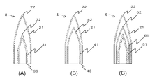
- 2 (A) to 2 (C) are modified examples of the optical member of the present invention, and all are modifications of the inner cover, and the shape of the outer cover 21 is the same.
- symbol similar to FIG. 1 is used, and description is abbreviate
- the optical member 3 in FIG. 2A is different in the shape of the inner cover 31 from that in FIG. 1, and is longer in length than the inner cover 11 in FIG. 1, and the tapered portion is a curve closer to a straight line. is there.
- the shape of the inner surface of the inner cover 31 in FIG. 2 (A) is substantially similar to the shape of the outer surface, but the inner surface to the outer surface at the top portion 32 rather than the thickness from the inner surface to the outer surface at the bottom portion 33.
- the thickness up to is slightly thicker.
- the outer cover 21 has an outer cover 21 that extends from the top 32 of the inner cover 31 more than the inner dimension of the cross section perpendicular to the optical axis at the position of the top 32 of the inner cover 31.
- the length to the top 22 is longer.
- the 2B has an even larger inner cover 41, and the distance between the outer surface of the inner cover 41 and the inner surface of the outer cover 21 is close.
- the thickness between the inner surface and the outer surface is substantially uniform at the bottom 43 and the top 42.
- the outer cover 21 is further separated from the outer cover 21 from the top 42 of the inner cover 41 than the inner dimension of the cross section perpendicular to the optical axis at the position of the top 42 of the inner cover 41. The length to the top 22 is longer.
- the optical member 5 in FIG. 2C has double inner covers 51 and 61.
- the first inner cover 51 is substantially the same as the inner cover 31 of FIG. 2A, and a light source is disposed inside or below the hollow.
- the second inner cover 61 is substantially the same as the inner cover 41 of FIG. 2C, and the first inner cover 51 is disposed inside the hollow.
- the outer cover 21 has a second inner cover that is larger than the inner dimension of the cross section perpendicular to the optical axis at the position of the top portion 62 of the second inner cover 61 on the inner side. The length from the top part 62 of 61 to the top part 22 of the outer cover 21 is longer.
- Example 1 As Example 1, an illumination device using the optical member 1 having the inner cover 11 and the outer cover 21 having the shape shown in FIG.
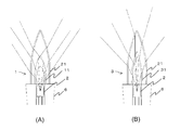
- FIG. 3A shows the result of calculating the ray path of the transmitted light in Example 1 by ray tracing.
- FIG. 4A shows the ray path of the reflected light by the outer cover in Example 1 calculated by ray tracing. It is the result.
- the lighting device includes an optical member 1 and an LED light source 2 as shown in FIG. 3A, and the LED light source 2 is embedded in the housing 6 so that light can be emitted upward.
- the inner cover 11 is disposed on the housing 6 so that the center thereof overlaps with the optical axis on the LED light source 2, and the outer cover 21 is disposed on the housing 6 so that the center overlaps with the optical axis on the outside of the inner cover 11. Has been.
- the outer cover 21 had a total height of about 35 mm and a bottom inner diameter of about 12 mm.
- the inner cover 11 had a height of about 20 mm, and the inner diameter of the bottom portion was about 8 mm.
- the inner cover 11 and the outer cover 21 are both molded using polycarbonate, but the inner cover 11 contains scattering particles as a scattering agent, and has a higher haze value than the outer cover 21. It has been.
- FIG. 5 (A) is a photograph of the lighting device of Example 1 in a state where it is turned on. There is a bright area at the tip of the inner cover 11, which is reflected by the outer cover and is observed as a line extending longitudinally from the top of the inner cover 11, and looks like a candle flame as a whole.
- FIG. 3A when the light emitted from the light source passes through the inner cover 11 and the outer cover 21, it is diffused and the radiation angle is expanded.
- FIG. 4A shows a path of reflected light reflected by the inner surface of the outer cover 21, but part of the light transmitted through the inner cover 11 is reflected by the inner surface of the outer cover 21 and observed. It is observed by a person.
- reflection by the inner surface of the inner cover 11, reflection by the outer surface of the inner cover 11, and reflection by the outer surface of the outer cover 21 also occur.
- the interaction results in a light distribution characteristic like a candle flame as a whole.
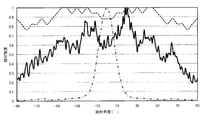
- FIG. 6 is a graph showing a light distribution state of the lighting device (solid line), the candle flame (dotted line), and the LED light source (one-dot chain line) of Example 1.
- FIG. 6 shows the result of measuring the light intensity at each emission angle up to the horizontal direction, which is ⁇ 90 ° centered on 0 ° directly above the light source.
- the vertical axis is the relative intensity (arbitrary unit) normalized with the maximum intensity being 1, and the horizontal axis is the radiation angle (°) around the light source.
- the dotted line in FIG. 6 shows the light distribution state of the candle flame measured as a reference, and emits light with a substantially uniform intensity at all radiation angles.
- the one-dot chain line in FIG. 6 shows the alignment state of the LED light source measured as a reference.
- the light source emits light almost directly from the light source and emits almost no light in the oblique direction. It is shown that.
- the solid line in FIG. 6 is the light distribution state of the illumination device of the first embodiment. Light from the LED light source with high directivity in the light distribution state of the alternate long and short dash line is reduced by the optical member in the vertical direction. It was confirmed that the light in the direction increased, the uniformity was improved as a whole, and it was changed to a light distribution state of the candle flame.
- Example 2 As Example 2, an illuminating device using the optical member 3 having the inner cover 31 and the outer cover 21 having the shape of FIG.
- FIG. 3B shows the optical path of the light beam transmitted in the second embodiment
- FIG. 4B shows the optical path of the light beam reflected by the outer cover in the second embodiment
- FIG. 5B is a photograph in a state where the lighting device of Example 2 is turned on.
- the lighting device includes an optical member 3 and an LED light source 2 as shown in FIG. 3B, and the LED light source 2 is embedded in the housing 6 so that light can be irradiated upward.
- the inner cover 31 is disposed on the housing 6 so that the center overlaps the optical axis on the LED light source 2
- the outer cover 21 is disposed on the housing 6 so that the center overlaps the optical axis outside the inner cover 11. Has been.
- the outer cover 21 had an overall height of about 35 mm and an inner diameter of the bottom of about 12 mm.
- the inner cover 31 had a height of about 23 mm and the bottom inner diameter was about 6 mm.
- the inner cover 31 and the outer cover 21 are both molded using polycarbonate, but the inner cover 31 contains scattering particles as a scattering agent, and has a higher haze value than the outer cover 21. It has been.
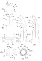
- Example 3 As Example 3, the optical member 7 having the shape shown in FIG. 7A to 7F are a top view, a side view, a bottom view, a DD line cross-sectional view, a EE line cross-sectional view, and a FF line cross-sectional view, respectively, of the optical member 7 of Example 3. (The pedestal 83 and the pedestal 93 are also described together).
- the optical member 7 includes an inner member 8 and an outer member 9.
- FIGS. 8A to 8D are a top view, a side view, a bottom view, and a cross-sectional view taken along the line DD, respectively, of the inner member 8.
- FIGS. 9A to 9D are a top view, a side view, a bottom view, and a cross-sectional view along the line DD, respectively, of the outer member 9.
- the inner member 8 includes an inner cover 81 and a pedestal 83 as shown in FIGS. 8 (A) to 8 (D).
- the inner cover 81 has substantially the same shape as that shown in FIG. 1, but a convex engaging portion 84 is provided at the position of the DD line on the outer periphery of the inner cover 81.
- the engaging portion 84 is configured to engage with a concave cutout portion 94 provided in the outer cover 91 of the outer member 9 shown in FIG. 9, and as shown in FIG. And the cutout portion 94 can be combined to prevent the outer cover 91 from rotating with respect to the inner cover 81.
- the pedestal 83 is made of a light-transmitting plastic, and includes a truncated cone having an outer diameter larger than the outer periphery of the inner cover 81 and the outer cover 91 (see FIG. 9) and decreasing in outer diameter.
- the upper surface of the pedestal 83 is joined to the lower surface of the pedestal 93 (see FIG. 9) of the outer member 9. Further, in the pedestal 83, a space for arranging the light source is provided around the optical axis c.
- a D-shaped cut portion 85 may be provided on a part of the outer edge of the pedestal 83, and a gate for injection molding the inner member 8 may be connected to the D-shaped cut portion 85.
- the gate residue formed by cutting off the excess resin after injection molding protrudes from the circular outer edge. And may interfere with other members (for example, a housing).
- a space generated by changing from a circular shape to a D-shape can be used as a region that allows the remaining gate to be formed after injection molding.
- the outer member 9 includes an outer cover 91 and a pedestal 93 as shown in FIGS. 9 (A) to 9 (D).
- the outer cover 91 has substantially the same shape as that shown in FIG. 1, but a concave notch 94 is provided at the position of the inner DD line of the outer cover 91 (and the pedestal 93).
- the notch 94 is configured to engage with an engaging portion 84 provided on the inner cover 81.
- the pedestal 93 is made of a light-transmitting plastic, has the same outer diameter as the upper surface of the pedestal 83 of the inner member 8, and the lower surface of the pedestal 93 is joined to the upper surface of the pedestal 83 (see FIG. 8).
- a space for arranging the inner member 8 is provided around the optical axis c.
- a D-shaped cut portion 95 may be provided at a part of the outer edge of the pedestal 93.
- a gate for injection molding the outer member 9 is connected to the D-shaped cut portion 95, and a space generated by the D-shaped cut portion 95 is formed. You may utilize as an area
- the D-shaped cut portion 95 may be used as a detent when the optical member 7 is attached to the housing 6 (see FIG. 10).
- the configurations of the D-shaped cut portion 85 of the pedestal 83 of the inner member 8 and the D-shaped cut portion 95 of the pedestal 93 of the outer member 9 shown in FIGS. 7 and 8 are merely examples, and the position, shape, and quantity are appropriately determined. Can be changed.
- the optical member 7 is configured in which the cylindrical portion and the cylindrical portion of the outer cover 91 are joined without leaving a gap.
- FIGS. 10A to 10D are a side view, a bottom view, a DD line cross-sectional view, and a EE line cross-sectional view, respectively, of an illuminating device that uses the optical member 7.
- the LED light source 2 is disposed in the space portion of the base 83 in the optical member 7.
- the optical member 7 is inserted from below the cylindrical housing 6 and arranged so that the D-shaped cut portion 95 of the pedestal 93 of the outer member 9 is engaged with the housing 6. 6 is fixed.
Landscapes
- Engineering & Computer Science (AREA)
- General Engineering & Computer Science (AREA)
- Non-Portable Lighting Devices Or Systems Thereof (AREA)
Abstract
【課題】指向性の高い光源からの光によってろうそくの炎のような配光特性を示す照明装置を提供する。 【解決手段】指向性の高い光を発する光源と、光源からの光が通過するように配置された一つまたは複数の透光性の内側カバーと、内側カバーの外側を覆う透光性で中空の外側カバーとを有し、外側カバーの一つ内側に配置された内側カバーの先端外形は、頂部に向かって先細りの形状であり、外側カバーは、一つ内側に配置された内側カバーの頂部の位置における光軸に垂直な断面の内寸法よりも、一つ内側に配置された内側カバーの頂部から外側カバーの頂部までの長さの方が長いことを特徴とする。
Description
本発明は、ろうそくの炎のような配光特性を示す照明装置に関し、特に、指向性の高い光源を備えた照明装置及び指向性の高い光をろうそくの炎のように見せるための光学部材に関する。
従来から、ろうそくの代わりに発光ダイオード(Light Emitting Diode:LED)を光源として利用した照明装置が提案されている。特許文献1は、LEDの上に、ろうそくの炎を模した外径形状に成形された光学部材を配置することで、LEDが発した光をろうそくの炎を模した発光状態とすることができることが開示されている。また、特許文献2には、LEDを中心に、光拡散カバーと、光拡散ランプケースを一定の間隔で二重に配設した燈明用ランプが開示されている。
また、特許文献3は、ろうそくの炎のような配光特性を得るための照明装置ではないが、LED照明装置の難燃性と安全性を確保し、かつ配光を制御するために、内側の第1の光学カバーと、外側の第2の光学カバーの2重構造として、いずれか一方を難燃性に優れる材料で構成し、他の一方を安全性に優れる材料で構成することが開示されている。
特許文献1では、ろうそくの炎に似せるため、炎を模した外径形状に成形された光学部材が、頂点付近の領域において光が散乱するような散乱処理を施す必要がある。散乱処理としては、例えば、表面に凹凸を形成させる粗面処理および梨地処理や、光散乱効果を有する散乱材を光学部材5内に含ませる処理等が挙げられている。しかし、特許文献1の光学部材は、散乱処理が必要である上に、光学部材の底部から頂点にかけて散乱係数を変化させる必要があることから、より簡易な製造方法のものが求められていた。
また、特許文献2に記載されているランプは、単に光拡散カバーの全体にサンドブラストを施しただけであり、光拡散カバーで拡散した光を光拡散ランプケースによって拡散させても、ろうそくの炎の発光状態とは大きく異なるものであった。
特許文献3のLED照明装置は、単に全周に配光範囲を広げるために、第1の光学カバー及び第2の光学カバーで光を拡散させているだけであり、ろうそくの炎のようには見えないし、見えるような配光とすることも困難であった。これは、特許文献3の第1の光学カバー及び第2の光学カバーの形状が、いずれも光軸に沿った断面において半円を描くだけであり、フレネル反射し難い形状であることから、ろうそくの炎のような複雑な配光状態にはならないためであると推測される。
本発明は、指向性の高い光源からの光によってろうそくの炎のような配光特性を示す照明装置を提供することを目的の一つとする。また、本発明は、指向性の高い光をろうそくの炎のような配光特性に変換する光学部材を提供することを目的とする。さらに、本発明においては、従来よりも簡単に製造可能であって、低コストで製造可能な照明装置または光学部材を提供することを目的とする。
前述した課題を解決するため、本発明の照明装置は、指向性の高い光を発する光源と、記光源からの光が通過するように配置された一つまたは複数の透光性の内側カバーと、 前記内側カバーの外側を覆う透光性で中空の外側カバーとを有し、前記外側カバーの一つ内側に配置された内側カバーの先端外形は、頂部に向かって先細りの形状であり、前記外側カバーは、前記一つ内側に配置された内側カバーの頂部の位置における光軸に垂直な断面の内寸法よりも、前記一つ内側に配置された内側カバーの頂部から前記外側カバーの頂部までの長さの方が長いことを特徴とする。
また、本発明の光学部材は、一つまたは複数の透光性の内側カバーと、前記内側カバーの外側を覆う透光性で中空の外側カバーとを有し、前記外側カバーの一つ内側に配置された内側カバーの先端外形は、頂部に向かって先細りの形状であり、前記外側カバーは、前記一つ内側に配置された内側カバーの頂部の位置における光軸に垂直な断面の内寸法よりも、前記一つ内側に配置された内側カバーの頂部から前記外側カバーの頂部までの長さの方が長いことを特徴とする。
さらに、上記照明装置及び光学部材において、前記外側カバーの内表面の各面は、前記一つ内側に配置された内側カバーの頂部の位置よりも前記外側カバーの頂部側の領域において、前記一つ内側に配置された内側カバーの頂部から前記外側カバーの内表面の各面の任意の点(ただし各面の境界は除く)までの長さよりも、前記任意の点における曲率半径の方が長いことが好ましい。
さらに、上記照明装置及び光学部材において、前記一つまたは複数の内側カバーは、前記外側カバーのヘーズ値と同じか、それよりも高いヘーズ値を有することが好ましい。さらに、前記一つ内側に配置された内側カバーは、内部が中空であり、内表面から外表面までの厚さが底部に比べて頂部で厚いことが好ましい。また、前記一つ内側に配置された内側カバーの外形は、ろうそくの炎を模した形状であってもよい。
本発明によれば、簡単な構造で指向性の高い光からろうそくの炎のような配光状態の照明装置を得ることができる。その他の効果については、発明を実施するための形態において述べる。
本発明の光学部材は、一つまたは複数の透光性の内側カバーと、内側カバーの外側を覆う透光性で中空の外側カバーとを有している。本発明の光学部材は、指向性の高い光をろうそくの炎の配光特性に類似させるため、まず内側カバーによってろうそくの炎の中心付近に存在する高輝度の内炎領域を作り、その高輝度の内炎領域の光を外側に配置された外側カバーによって反射、屈折させることで高輝度の領域の周囲に広がる淡い明るさの外炎領域を重ねることでろうそくの炎に近い視覚効果の照明を提供することができる。
本発明の内側カバーは、一つでもよいし、複数の内側カバーを重ねて配置してもよい(図2(C)参照)。内側カバーは、高輝度の内炎領域に似せるため、先端外形が頂部に向かって先が細くなる先細りの形状を採用し、光源からの光が先端に集中し、先端部分において、広い放射角度で光が照射するようにした。先端外形としては、例えば、円錐形、角錐形、半紡錘形などが挙げられる。また、内側カバー全体が円錐形、角錐形または半紡錘形であってもよいが、頂部側に円錐形、角錐形または半紡錘形を採用し、底部側においては幅が一定の円柱、角柱などの領域やいったん広がった幅を底部側で若干狭くする領域を設け、内側カバー全体の外形としてろうそくの炎を模した形状としてもよい。
本発明の内側カバーは、内部が充填されていてもよいが、内部を中空とすることがコスト及び軽量化の点で好ましい。さらに、内部を中空とすることで、光が内側カバーの外表面だけではなく、内表面においても反射、屈折するため、より複雑な配光状態とすることができ、高輝度の内炎領域に近づかせることもできる。内部を中空とした場合、内側カバーの内表面から外表面までの厚さを底部に比べて頂部で厚くすることにより、光源からの光をより先端に集中させて高輝度とすることが好ましい。
本発明の外側カバーは、内部に内側カバーが配置されるように中空であり、一つ内側に配置された内側カバーの頂部の位置における光軸に垂直な断面の内寸法(図1のBの長さ)よりも、内側カバーの頂部から外側カバーの頂部までの長さ(図1のAの長さ)の方が長い。かかる構造は、外側カバーが内側カバーの先端に対して縦長であることを意味し、これにより、内側カバーの先端からの光の多くが外側カバーに対して斜めに入射し、内側カバーの先端に集中した光をフレネル反射させ易く構成されている。また、本発明の外側カバーの外表面及び内表面は、先端が頂部に向かって細くなるような形状、例えば、円錐形、角錐形、半紡錘形を採用することが好ましい。さらに、外側カバーの内表面の各面は、一つ内側に配置された内側カバーの頂部の位置よりも外側カバーの頂部側の領域(図1のAの領域)において、内側カバーの頂部から外側カバーの内表面の各面の任意の点(ただし各面の境界は除く)までの長さよりも、各面の任意の点における曲率半径の方が長いことが好ましい。このように構成することで、外側カバーの内表面によって、内側カバーの先端から上方に向かって照射される光を観察者に向かって反射しやすくされており、外縁領域としての効果を高めることができる。内表面の各面が、ぶつかり合う境界(例えば、円柱部分と円錐部分との境界、先端の頂点)については、上記条件には含まれない。特に、内表面の先端に位置する頂点は、上記条件からは除かれる。円柱部分と円錐部分との境界が滑らかな曲面で構成されている場合は、かかる局面の曲率半径と比較される。なお、光軸を含む断面において、外側カバーの内表面の全部又は一部が曲面ではなく、平面であった場合(例えば外側カバーの先端外形が円錐形だった場合)は、曲率半径は無限大となるので、内側カバーの頂部から外側カバーの内表面の任意の点(ただし内表面の頂点は除く)までの長さよりも長くなる。
内側カバーのヘーズ値(曇り度)は、外側カバーと同じか、それよりも高いヘーズ値を有することが好ましい。ヘーズ値を高くすることで内側カバーで形成される高輝度の内炎領域の全体に光を広げ、よりろうそくの炎に近い配光特性を得ることができる。内側カバーと外側カバーとが、同じ材料を使用し、特に何らの散乱処理を施さないで製造された場合は同じヘーズ値となる。ヘーズ値を高くするため、内側カバーの材料中に散乱剤を混入させたり、別の材料を使用してもよいし、同じ材料を使用して内側カバーを成形した後、表面をやすりやサンドブラストによって粗面化してもよい。内側カバーはヘーズ値および内側カバーの厚みを調整することにより中空部(内側カバー内部)を視認できる程度の光透過性能とすることが好ましい。外側カバーは、内側カバーが視認可能な程度の光透過性能であることが好ましく、散乱性能を有していないか、内側カバーのヘーズ値以下であることが好ましい。
内側カバー及び外側カバーは、透光性を有する材料であれば、完全に透明なものでなくてもよい。材料としては、プラスチックであっても、ガラスであってもよいが、成形の容易性、コスト、軽量化の観点からプラスチックであることが好ましい。プラスチックとしては、例えば、PMMA(ポリメチルメタクリレート)、PC(ポリカーボネート)等を使用することができる。また、これらの材料に散乱剤を混入させてもよいし、染料を混在させたり、コーティングすることで着色してもよい。
内側カバー及び外側カバーは比較的簡単な形状であるので、射出成形することによって大量生産することが可能である。射出成形でカバーを成形する場合、内側カバー及び外側カバーを別々に設計することが好ましい。ただし、内側カバー及び外側カバーは、図1、図2のように、別々に構成されていてもよいが、同一材料で製造する場合は、内側カバーと外側カバーを一体として成形してもよい。例えば、内側カバーの底部の外周の一部と外側カバーの底部の内周の一部とを連結させてもよい。
本発明の照明装置は、指向性の高い光を照射する光源と、上記のような光学部材とを有し、光学部材の一番内側の内側カバーの底部から、中心に光軸を併せて頂部に向けて指向性の高い光が照射される。光源から光学部材までの間に、ミラー、プリズム、光ファイバー等によって光の進行方向を変化させてもよいし、ビームスプリッタ-等によって複数の光に分割して、それぞれの光に光学部材を配置するようにしてもよい。光源として、典型的には、LED光源を利用することができるが、LED光源以外であっても指向性の高い光を照射できればよい。
図1は、本発明の光学部材の一実施形態の光軸に沿った断面形状を示している。図1の光学部材1は、上向きに尖った先端が配置された一つの内側カバー11と、内側カバー11の外側に、内側カバー11を覆って、上向きに尖った先端が配置された外側カバー21とを備えている。内側カバー11と外側カバー21は、中心が光軸となるように配置されている。図1において、光源は図示されていないが、光学部材1は、中心を光軸cとして下方から上方に指向性の高い光が照射されるように配置される。
図1の内側カバー11は、内部が中空であり、先端に頂部12を有し、下端に底部13を有しており、底部13の光軸に垂直な断面形状は円形である。内側カバー11は、まず底部13からほぼ均一の厚さで垂直に延びて円柱状となっているが、その後、頂部12に向けて徐々に半紡錘形となっている。図1では、紡錘形の部分は、外表面の曲率に比べて、内表面の曲率の方が大きくなっており、頂部12に向かって肉厚となるように構成されている。図1に示すように、底部13における内表面から外表面までの厚さbよりも、頂部12における内表面から外表面までの厚さaの方を厚くすることで、内側カバー11の先端に光を導き易くすることができる。
図1の外側カバー21は、内部が中空であり、先端に頂部22を有し、下端に底部23を有しており、底部22の光軸に垂直な断面形状は円形である。外側カバー21は、まず底部23からほぼ均一の厚さで垂直に延びて円柱状となっているが、その後、頂部22に向けて半紡錘形となっている。図1の外側カバー21は、半紡錘形の部分でもほぼ均一の厚さであり、底部23における厚さも頂部22における厚さもほぼ同じである。
また、外側カバー21は、一つ内側に配置された内側カバー11との関係において、内側カバー11の頂部12の位置における光軸cに垂直な断面の内寸法Bよりも、内側カバー11の頂部12から外側カバー21の頂部22までの長さAの方が長い。つまり、外側カバー21は、内側カバー11の頂部12の位置よりも頂部22側の領域(図1のAの領域)において、縦長の形状である。さらに、その領域Aにおける外側カバー21の内表面は、図1から明らかなように、頂点(頂部22の内表面)を除く全体が緩やかな曲面となっており、内側カバー11の頂部12から外側カバー21の内表面の任意の点(ただし内表面の頂点は除く)までの長さよりも、内表面の任意の点における曲率半径の方が長いことは明らかである。
図2(A)~(C)は、本発明の光学部材の変形例であり、いずれも内側カバーの態様を変更したものであり、外側カバー21の形状については同じである。外側カバー21については、図1と同様の符号を使用し、ここでは説明を省略する。
図2(A)の光学部材3は、図1に比べて、内側カバー31の形状が異なり、図1の内側カバー11と比べると、より縦長であり、先細りの部分がより直線に近い曲線である。図2(A)の内側カバー31の内表面の形状は、外表面の形状とほぼ相似しているが、底部33における内表面から外表面までの厚さよりも、頂部32における内表面から外表面までの厚さの方が若干厚くなっている。また、図2(A)の光学部材3においても、外側カバー21は、内側カバー31の頂部32の位置における光軸に垂直な断面の内寸法よりも、内側カバー31の頂部32から外側カバー21の頂部22までの長さの方が長い。
図2(B)の光学部材4は、さらに大きな内側カバー41を有するものであり、内側カバー41の外表面と外側カバー21の内表面との距離が近接している。図2(B)の内側カバー41は、内表面と外表面との間の厚さは底部43でも頂部42でもほぼ均一である。また、図2(B)の光学部材4においても、外側カバー21は、内側カバー41の頂部42の位置における光軸に垂直な断面の内寸法よりも、内側カバー41の頂部42から外側カバー21の頂部22までの長さの方が長い。
図2(C)の光学部材5は、2重の内側カバー51、61を有している。第1の内側カバー51は、図2(A)の内側カバー31とほぼ同じであり、中空の内部又はその下に光源が配置される。第2の内側カバー61は、図2(C)の内側カバー41とほぼ同じであり、中空の内部に第1の内側カバー51が配置される。図2(C)の光学部材5において、外側カバー21は、その一つ内側の第2の内側カバー61の頂部62の位置における光軸に垂直な断面の内寸法よりも、第2の内側カバー61の頂部62から外側カバー21の頂部22までの長さの方が長い。
[実施例1] 実施例1として、図1の形状の内側カバー11及び外側カバー21を有する光学部材1を使用した照明装置を製造した。図3(A)は、実施例1における透過光の光線経路を光線追跡により算出した結果であり、図4(A)は、実施例1における外側カバーによる反射光の光線経路を光線追跡により算出した結果である。照明装置は、図3(A)に示すように、光学部材1とLED光源2とを有しており、筐体6内に上向きに光が照射できるようにLED光源2が埋設されており、LED光源2の上に中心が光軸と重なるように内側カバー11が筐体6上に配置され、内側カバー11の外側に中心が光軸と重なるように外側カバー21が筐体6上に配置されている。
実施例1では、外側カバー21は全体の高さが約35mmであり、底部の内径が約12mmであった。内側カバー11は高さが約20mmであり、底部の内径は約8mmであった。内側カバー11及び外側カバー21は、いずれもポリカーボネートを用いて成形されたものであるが、内側カバー11には、散乱剤として散乱粒子が混入されており、外側カバー21に比べてヘーズ値が高められている。
図5(A)は、実施例1の照明装置を点灯した状態の写真である。内側カバー11の先端部分において高輝度の領域があり、それが外側カバーによって反射され、内側カバー11の頂部から縦方向に延びる線のように観察され、全体としてろうそくの炎のように見える。この点、図3(A)に示すように、光源から射出された光は、内側カバー11及び外側カバー21を透過する際に、拡散し放射角度が広げられる。図4(A)には、外側カバー21の内表面で反射される反射光の経路を示しているが、内側カバー11を透過した光の一部が外側カバー21の内表面で反射され、観察者によって観察されるのである。ただし、図示していないが、本発明の光学部材では、その他に内側カバー11の内表面による反射、内側カバー11の外表面による反射、外側カバー21の外表面による反射も生じており、これらの相互作用によって全体としてろうそくの炎のような配光特性となっている。
図6は、実施例1の照明装置(実線)、ろうそくの炎(点線)及びLED光源(一点鎖線)の配光状態を示すグラフである。図6は、光源の真上を0°として、そこを中心として±90°となる水平方向までの各放射角度の光強度を1度ごとに測定した結果である。縦軸は、最大強度を1として規格化した相対強度(任意単位)であり、横軸は、光源を中心とした放射角度(°)である。図6の点線は、参考として測定したろうそくの炎の配光状態を示しており、全放射角度において略均一な強度の光を放射している。図6の一点鎖線は、参考として測定したLED光源の配向状態であり、ほぼ光源から真上に向かって光を放射しており、斜め方向には殆ど発光していない非常に指向性の高い光源であることを示している。図6の実線は、実施例1の照明装置の配光状態であり、一点鎖線の配光状態の指向性の高いLED光源からの光が、光学部材によって、垂直方向の光が減って、斜め方向の光が増加し、全体として均一性が高まり、ろうそくの炎の配光状態に近いものに変化していることが確認された。
[実施例2] 実施例2として、図2(A)の形状の内側カバー31及び外側カバー21を有する光学部材3を使用した照明装置を製造した。図3(B)は、実施例2における透過光の光線の光路を示し、図4(B)は、実施例2における外側カバーによる反射光の光線の光路を示す。また、図5(B)は、実施例2の照明装置を点灯した状態の写真である。照明装置は、図3(B)に示すように、光学部材3とLED光源2とを有しており、筐体6内に上向きに光が照射できるようにLED光源2が埋設されており、LED光源2の上に中心が光軸と重なるように内側カバー31が筐体6上に配置され、内側カバー11の外側に中心が光軸と重なるように外側カバー21が筐体6上に配置されている。
実施例2では、外側カバー21は全体の高さが約35mmであり、底部の内径が約12mmであった。内側カバー31は高さが約23mmであり、底部の内径は約6mmであった。内側カバー31及び外側カバー21は、いずれもポリカーボネートを用いて成形されたものであるが、内側カバー31には、散乱剤として散乱粒子が混入されており、外側カバー21に比べてヘーズ値が高められている。
[実施例3] 実施例3として、図7に示す形状の光学部材7を製造した。図7(A)~(F)は、各々、実施例3の光学部材7の上面図、側面図、底面図、D-D線断面図、E-E線断面図及びF-F線断面図(台座83及び台座93も合わせて記載)である。光学部材7は、内側部材8と外側部材9とから構成される。図8(A)~(D)は、各々、内側部材8の上面図、側面図、底面図及びD-D線断面図である。図9(A)~(D)は、各々、外側部材9の上面図、側面図、底面図及びD-D線断面図である。
内側部材8は、図8(A)~(D)などに示すように、内側カバー81と台座83とから構成される。内側カバー81は、図1に示すものとほぼ同様の形状であるが、内側カバー81の外周のD-D線の位置に凸状の係合部84が設けられる。係合部84は、図9に示す外側部材9の外側カバー91に設けられた凹状の切欠き部94と係合するように構成され、図7(D)に示すように、係合部84と切欠き部94とを組み合わせることによって、内側カバー81に対して外側カバー91が回動することを防止できる。
台座83は、透光性を有するプラスチックから構成され、内側カバー81及び外側カバー91(図9参照)の外周より大きな外径を有し、下方に向かって外径が小さくなる円錐台を含む。台座83の上面は、外側部材9の台座93(図9参照)の下面と接合される。また、台座83において、光軸cの周りには光源を配置するための空間が設けられる。台座83の外縁の一部にはD型カット部85が設けられてもよく、D型カット部85には、内側部材8を射出成形するためのゲートを接続してもよい。D型カット部85を設けずに、台座83の外縁を円形とし、その外縁にゲートを接続した場合は、射出成形後に余分な樹脂を切除したことによって形成されるゲート残りが円形の外縁から突出することがあり、他の部材(たとえば筐体等)と干渉する可能性があった。D型カット部85を設けた場合、円形からD型とすることによって生じる空間を、射出成形後に形成されるゲート残りの突出を許容する領域として使用することができる。
外側部材9は、図9(A)~(D)などに示すように、外側カバー91と台座93とから構成される。外側カバー91は、図1に示すものとほぼ同様の形状であるが、外側カバー91(及び台座93)の内周のD-D線の位置に凹状の切欠き部94が設けられる。切欠き部94は、内側カバー81に設けられた係合部84と係合するように構成される。
台座93は、透光性を有するプラスチックから構成され、内側部材8の台座83の上面と同一の外径を有し、台座93の下面が台座83(図8参照)の上面と接合される。また、台座93において、光軸cの周りには内側部材8を配置するための空間が設けられる。台座93の外縁の一部にはD型カット部95が設けられてもよく、D型カット部95に外側部材9を射出成形するためのゲートを接続し、D型カット部95によって生じる空間をゲート残りの突出を許容する領域として利用してもよい。さらに、D型カット部95は、光学部材7を筐体6(図10参照)に取り付けた際に、回り止めとして利用してもよい。なお、図7及び図8に示した内側部材8の台座83のD型カット部85及び外側部材9の台座93のD型カット部95の構成は単なる例示であり、位置、形状、数量は適宜変更することができる。
そして、図8に示した内側部材8と図9に示した外側部材9とを組み合わせると、図7に示すように、係合部84と切欠き部94とが係合し、内側カバー81の円筒部と外側カバー91の円筒部とが間隙を空けずに接合した光学部材7が構成される。
さらに、実施例3として、かかる光学部材7を使用した照明装置を製造した。図10(A)~(D)は、各々、光学部材7を使用した照明装置の側面図、底面図、D-D線断面図及びE-E線断面図である。光学部材7における台座83の空間部分にはLED光源2が配置される。かかる光学部材7は、円筒形の筐体6の下方から挿入され、外側部材9の台座93のD型カット部95が筐体6に係合するように配置し、図示しない固定部材によって筐体6に固定される。
1 光学部材
2 光源
11 内側カバー
21 外側カバー
2 光源
11 内側カバー
21 外側カバー
Claims (10)
- 指向性の高い光を発する光源と、
前記光源からの光が通過するように配置された一つまたは複数の透光性の内側カバーと、
前記内側カバーの外側を覆う透光性で中空の外側カバーとを有し、
前記外側カバーの一つ内側に配置された内側カバーの先端外形は、頂部に向かって先細りの形状であり、
前記外側カバーは、前記一つ内側に配置された内側カバーの頂部の位置における光軸に垂直な断面の内寸法よりも、前記一つ内側に配置された内側カバーの頂部から前記外側カバーの頂部までの長さの方が長いことを特徴とする照明装置。 - 前記外側カバーの内表面の各面は、前記一つ内側に配置された内側カバーの頂部の位置よりも前記外側カバーの頂部側の領域において、前記一つ内側に配置された内側カバーの頂部から前記外側カバーの内表面の各面の任意の点(ただし各面の境界は除く)までの長さよりも、前記任意の点における曲率半径の方が長いことを特徴とする請求項1に記載の照明装置。
- 前記一つ内側に配置された内側カバーの外形は、ろうそくの炎を模した形状であることを特徴とする請求項1または2に記載の照明装置。
- 前記一つまたは複数の内側カバーは、前記外側カバーのヘーズ値と同じか、それよりも高いヘーズ値を有することを特徴とする請求項1乃至3の何れか1項に記載の照明装置。
- 前記一つ内側に配置された内側カバーは、内部が中空であり、内表面から外表面までの厚さが底部に比べて頂部で厚いことを特徴とする請求項1乃至4の何れか1項に記載の照明装置。
- 一つまたは複数の透光性の内側カバーと、
前記内側カバーの外側を覆う透光性で中空の外側カバーとを有し、
前記外側カバーの一つ内側に配置された内側カバーの先端外形は、頂部に向かって先細りの形状であり、
前記外側カバーは、前記一つ内側に配置された内側カバーの頂部の位置における光軸に垂直な断面の内寸法よりも、前記一つ内側に配置された内側カバーの頂部から前記外側カバーの頂部までの長さの方が長いことを特徴とする光学部材。 - 前記外側カバーの内表面の各面は、前記一つ内側に配置された内側カバーの頂部の位置よりも前記外側カバーの頂部側の領域において、前記一つ内側に配置された内側カバーの頂部から前記外側カバーの内表面の各面の任意の点(ただし各面の境界は除く)までの長さよりも、前記任意の点における曲率半径の方が長いことを特徴とする請求項6に記載の光学部材。
- 前記一つ内側に配置された内側カバーの外形は、ろうそくの炎を模した形状であることを特徴とする請求項6または7に記載の光学部材。
- 前記一つまたは複数の内側カバーは、前記外側カバーのヘーズ値と同じか、それよりも高いヘーズ値を有することを特徴とする請求項6乃至8何れか1項に記載の光学部材。
- 前記一つ内側に配置された内側カバーは、内部が中空であり、内表面から外表面までの厚さが底部に比べて頂部で厚いことを特徴とする請求項6至9何れか1項に記載の光学部材。
Priority Applications (1)
| Application Number | Priority Date | Filing Date | Title |
|---|---|---|---|
| PCT/JP2015/061401 WO2016166804A1 (ja) | 2015-04-13 | 2015-04-13 | 照明装置及び光学部材 |
Applications Claiming Priority (1)
| Application Number | Priority Date | Filing Date | Title |
|---|---|---|---|
| PCT/JP2015/061401 WO2016166804A1 (ja) | 2015-04-13 | 2015-04-13 | 照明装置及び光学部材 |
Publications (1)
| Publication Number | Publication Date |
|---|---|
| WO2016166804A1 true WO2016166804A1 (ja) | 2016-10-20 |
Family
ID=57126600
Family Applications (1)
| Application Number | Title | Priority Date | Filing Date |
|---|---|---|---|
| PCT/JP2015/061401 Ceased WO2016166804A1 (ja) | 2015-04-13 | 2015-04-13 | 照明装置及び光学部材 |
Country Status (1)
| Country | Link |
|---|---|
| WO (1) | WO2016166804A1 (ja) |
Citations (5)
| Publication number | Priority date | Publication date | Assignee | Title |
|---|---|---|---|---|
| JPS53100689A (en) * | 1977-02-15 | 1978-09-02 | Moriyama Sangyo Kk | Light source cap for decorative lamp |
| JP2000251513A (ja) * | 1999-02-26 | 2000-09-14 | Keijiro Yamaoka | 省エネ燈明用ランプ |
| JP2002042519A (ja) * | 2000-07-24 | 2002-02-08 | Matsushita Electric Works Ltd | 照明装置 |
| JP2011076833A (ja) * | 2009-09-30 | 2011-04-14 | Sharp Corp | Led照明装置 |
| JP2012506125A (ja) * | 2008-10-16 | 2012-03-08 | オスラム・シルバニア・インコーポレイテッド | 体積散乱用要素を有する発光ダイオードベースのランプ |
-
2015
- 2015-04-13 WO PCT/JP2015/061401 patent/WO2016166804A1/ja not_active Ceased
Patent Citations (5)
| Publication number | Priority date | Publication date | Assignee | Title |
|---|---|---|---|---|
| JPS53100689A (en) * | 1977-02-15 | 1978-09-02 | Moriyama Sangyo Kk | Light source cap for decorative lamp |
| JP2000251513A (ja) * | 1999-02-26 | 2000-09-14 | Keijiro Yamaoka | 省エネ燈明用ランプ |
| JP2002042519A (ja) * | 2000-07-24 | 2002-02-08 | Matsushita Electric Works Ltd | 照明装置 |
| JP2012506125A (ja) * | 2008-10-16 | 2012-03-08 | オスラム・シルバニア・インコーポレイテッド | 体積散乱用要素を有する発光ダイオードベースのランプ |
| JP2011076833A (ja) * | 2009-09-30 | 2011-04-14 | Sharp Corp | Led照明装置 |
Similar Documents
| Publication | Publication Date | Title |
|---|---|---|
| US8382328B2 (en) | Lighting device having fully developed lighting effect | |
| TWI524030B (zh) | 發光裝置及照明器具 | |
| KR101114183B1 (ko) | 조명 조립체 | |
| CN104379992B (zh) | 光束控制部件、发光装置以及照明装置 | |
| RU2645250C2 (ru) | Световод для изменения паттерна распределения света | |
| JP5172592B2 (ja) | 光学素子および発光装置 | |
| JP5306799B2 (ja) | 光学素子および発光装置 | |
| US9297512B2 (en) | Light flux controlling member, light emitting device and illumination apparatus | |
| CN103836541B (zh) | 一种导光件及平行光源照明装置 | |
| CN102829437B (zh) | 光罩及具光罩的灯具 | |
| JP2012150274A (ja) | 光束制御部材、この光束制御部材を備えた発光装置およびこの発光装置を備えた照明装置 | |
| JP6290040B2 (ja) | 光束制御部材、発光装置および照明装置 | |
| JP2012209049A (ja) | Led照明装置およびレンズ | |
| US20170108193A1 (en) | Illuminating device | |
| US20160230952A1 (en) | Lighting unit | |
| WO2016009798A1 (ja) | 光束制御部材、発光装置および照明装置 | |
| CN104797880A (zh) | 具有三维效果的车辆信号装置 | |
| CN111886446B (zh) | 一种用于改变光分布的光学装置 | |
| CN108916811A (zh) | 光学组件与车灯 | |
| JP6012972B2 (ja) | 照明装置 | |
| JP2015156294A (ja) | 照明装置及び光学部材 | |
| RU2672051C2 (ru) | Оптический элемент, осветительное устройство и светильник | |
| JP5707159B2 (ja) | 照明用レンズおよびこれを備えた照明装置 | |
| TWM457135U (zh) | 具有微結構的燈具 | |
| JP5712271B2 (ja) | 光学素子および発光装置 |
Legal Events
| Date | Code | Title | Description |
|---|---|---|---|
| 121 | Ep: the epo has been informed by wipo that ep was designated in this application |
Ref document number: 15889142 Country of ref document: EP Kind code of ref document: A1 |
|
| NENP | Non-entry into the national phase |
Ref country code: DE |
|
| 122 | Ep: pct application non-entry in european phase |
Ref document number: 15889142 Country of ref document: EP Kind code of ref document: A1 |
|
| NENP | Non-entry into the national phase |
Ref country code: JP |