WO2016158408A1 - 懸架装置用ばねの製造方法及び懸架装置用ばね - Google Patents
懸架装置用ばねの製造方法及び懸架装置用ばね Download PDFInfo
- Publication number
- WO2016158408A1 WO2016158408A1 PCT/JP2016/058284 JP2016058284W WO2016158408A1 WO 2016158408 A1 WO2016158408 A1 WO 2016158408A1 JP 2016058284 W JP2016058284 W JP 2016058284W WO 2016158408 A1 WO2016158408 A1 WO 2016158408A1
- Authority
- WO
- WIPO (PCT)
- Prior art keywords
- spring
- quenching
- suspension
- steel material
- manufacturing
- Prior art date
- Legal status (The legal status is an assumption and is not a legal conclusion. Google has not performed a legal analysis and makes no representation as to the accuracy of the status listed.)
- Ceased
Links
Images




Classifications
-
- B—PERFORMING OPERATIONS; TRANSPORTING
- B60—VEHICLES IN GENERAL
- B60G—VEHICLE SUSPENSION ARRANGEMENTS
- B60G11/00—Resilient suspensions characterised by arrangement, location or kind of springs
- B60G11/02—Resilient suspensions characterised by arrangement, location or kind of springs having leaf springs only
- B60G11/04—Resilient suspensions characterised by arrangement, location or kind of springs having leaf springs only arranged substantially parallel to the longitudinal axis of the vehicle
-
- B—PERFORMING OPERATIONS; TRANSPORTING
- B60—VEHICLES IN GENERAL
- B60G—VEHICLE SUSPENSION ARRANGEMENTS
- B60G11/00—Resilient suspensions characterised by arrangement, location or kind of springs
- B60G11/14—Resilient suspensions characterised by arrangement, location or kind of springs having helical, spiral or coil springs only
-
- C—CHEMISTRY; METALLURGY
- C21—METALLURGY OF IRON
- C21D—MODIFYING THE PHYSICAL STRUCTURE OF FERROUS METALS; GENERAL DEVICES FOR HEAT TREATMENT OF FERROUS OR NON-FERROUS METALS OR ALLOYS; MAKING METAL MALLEABLE, e.g. BY DECARBURISATION OR TEMPERING
- C21D1/00—General methods or devices for heat treatment, e.g. annealing, hardening, quenching or tempering
- C21D1/56—General methods or devices for heat treatment, e.g. annealing, hardening, quenching or tempering characterised by the quenching agents
- C21D1/60—Aqueous agents
-
- C—CHEMISTRY; METALLURGY
- C21—METALLURGY OF IRON
- C21D—MODIFYING THE PHYSICAL STRUCTURE OF FERROUS METALS; GENERAL DEVICES FOR HEAT TREATMENT OF FERROUS OR NON-FERROUS METALS OR ALLOYS; MAKING METAL MALLEABLE, e.g. BY DECARBURISATION OR TEMPERING
- C21D9/00—Heat treatment, e.g. annealing, hardening, quenching or tempering, adapted for particular articles; Furnaces therefor
- C21D9/02—Heat treatment, e.g. annealing, hardening, quenching or tempering, adapted for particular articles; Furnaces therefor for springs
-
- C—CHEMISTRY; METALLURGY
- C22—METALLURGY; FERROUS OR NON-FERROUS ALLOYS; TREATMENT OF ALLOYS OR NON-FERROUS METALS
- C22C—ALLOYS
- C22C38/00—Ferrous alloys, e.g. steel alloys
-
- C—CHEMISTRY; METALLURGY
- C22—METALLURGY; FERROUS OR NON-FERROUS ALLOYS; TREATMENT OF ALLOYS OR NON-FERROUS METALS
- C22C—ALLOYS
- C22C38/00—Ferrous alloys, e.g. steel alloys
- C22C38/04—Ferrous alloys, e.g. steel alloys containing manganese
-
- C—CHEMISTRY; METALLURGY
- C22—METALLURGY; FERROUS OR NON-FERROUS ALLOYS; TREATMENT OF ALLOYS OR NON-FERROUS METALS
- C22C—ALLOYS
- C22C38/00—Ferrous alloys, e.g. steel alloys
- C22C38/60—Ferrous alloys, e.g. steel alloys containing lead, selenium, tellurium, or antimony, or more than 0.04% by weight of sulfur
-
- F—MECHANICAL ENGINEERING; LIGHTING; HEATING; WEAPONS; BLASTING
- F16—ENGINEERING ELEMENTS AND UNITS; GENERAL MEASURES FOR PRODUCING AND MAINTAINING EFFECTIVE FUNCTIONING OF MACHINES OR INSTALLATIONS; THERMAL INSULATION IN GENERAL
- F16F—SPRINGS; SHOCK-ABSORBERS; MEANS FOR DAMPING VIBRATION
- F16F1/00—Springs
- F16F1/02—Springs made of steel or other material having low internal friction; Wound, torsion, leaf, cup, ring or the like springs, the material of the spring not being relevant
Definitions
- the present invention relates to a method for manufacturing a suspension device spring and a suspension device spring.
- a suspension device spring such as a coil spring or a leaf spring (lap leaf spring) is provided in a suspension device for suspending an axle.
- the suspension device spring connects the vehicle body side and the wheel side to support the vehicle weight, and plays a role of buffering an impact applied to the vehicle body through the wheel.
- a suspension device spring that can cope with high stress and can realize weight reduction is desired.
- suspension device spring such as SUP9, SUP9A, and SUP11A (JIS standard) has been used as a material for the suspension spring.
- the suspension device spring is manufactured by heat-treating a steel wire or a steel plate processed into a predetermined shape and shape into a spring shape in a hot or cold state, and performing a heat treatment. As the heat treatment, oil quenching and tempering are often performed. Suspension device springs are commercialized after such heat treatment, through shot peening, setting, painting, and the like.
- Patent Document 1 describes weight percent (hereinafter the same), C: 0.30 to 0.75%, Si: 1.0. About 4.0%, Mn: 0.5-1.5%, Cr: 0.1-2.0% and Ni ⁇ 2.0%, with the balance being Fe and inevitable impurities, Disclosed is a method for producing a high strength spring steel with excellent fatigue strength and sag resistance by quenching and reducing the amount of retained austenite after oil quenching to less than 10%, followed by tempering. .
- the suspension spring has excellent toughness with mechanical strength and good toughness.
- high temperature tempering has often been performed after quenching in order to provide sufficient fatigue durability while supporting high stress design.
- high-temperature tempering usually involves heat treatment at a high temperature exceeding about 400 ° C., and such heat treatment may be repeated several times. Therefore, a large amount of heat is additionally added to steel that has already been quenched. It takes time to spend. Therefore, the manufacturing method of the suspension device spring that undergoes high temperature tempering does not meet the recent demand for downsizing of the production line.
- the present invention provides a method for manufacturing a suspension device spring that can manufacture a suspension device spring having good mechanical strength and toughness with high productivity in a compact production line, and a suspension device manufactured by the method.
- the object is to provide a spring.
- the suspension device spring manufacturing method is, in mass%, C: 0.10% or more and 0.39% or less, Mn: 1.00% or more and 1.50% or less.
- B a forming step of forming a steel material containing 0.0005% or more and 0.003% or less into a spring shape in hot or cold, and a heat transfer coefficient equivalent to or close to water in the formed steel material
- a quenching step of quenching with a medium having a medium and the suspension spring is manufactured without tempering the quenched steel material to 400 ° C. or higher.
- suspension device spring according to the present invention is manufactured by the above-described suspension device manufacturing method.
- the present invention it is possible to provide a method for manufacturing a suspension spring that can manufacture a suspension spring having good mechanical strength and toughness with high productivity on a compact production line. Since the suspension spring manufactured by the manufacturing method is provided with a compressive residual stress having a deep distribution in the surface layer, it is difficult to cause delayed fracture and has excellent fatigue durability.
- the suspension device spring manufacturing method includes a coil spring (suspension device coil spring) provided in a suspension device provided in a vehicle, a plate spring (suspension device leaf spring) constituting a laminated leaf spring, and the like.
- the present invention relates to a method of manufacturing a suspension device spring.
- the material is formed into a spring shape in the hot or cold state, subjected to quenching with a medium having a heat transfer coefficient equivalent to or close to that of water, and the quenched steel material is 400 ° C or higher after quenching. It is a method for manufacturing a suspension spring without tempering.
- the material for the spring for the suspension device manganese boron steel having a particularly low carbon content is employed.
- FIG. 1 is a diagram showing a coil spring for a suspension device manufactured by a method for manufacturing a spring for a suspension device according to an embodiment of the present invention.
- FIG. 1A is a perspective view showing a suspension device provided with a coil spring for a suspension device
- FIG. 1B is a longitudinal sectional view of the coil spring for the suspension device.
- the vehicle is provided with a suspension device 8A for suspending an axle to which wheels W are attached.
- left and right independent strut suspension devices 8A and 8A are shown as suspension devices.
- a pair of left and right suspension devices 8A and 8A includes a suspension device coil spring (coil spring) 1 manufactured by the suspension device manufacturing method according to the present embodiment, and a spring seat 2a. The spring seat 2b and the shock absorber 3 are provided.
- the shock absorber 3 has a damping force generating mechanism composed of a cylindrical cylinder, a rod inserted into the cylinder, an orifice, and the like.
- a piston is provided at one end of the rod, and the working fluid inside the cylinder flows by the expansion and contraction of the rod, and a damping force is generated by the resistance accompanying the flow.
- One end of the shock absorber 3 is supported by the knuckle 6 via the bracket 5 and the other end is connected to the vehicle body side (not shown).
- a spring seat 2a is fixed to the cylinder of the shock absorber 3
- a spring seat 2b is fixed to the other end.
- a coil spring 1 is interposed between the spring seat 2a and the spring seat 2b.
- the coil spring 1 is formed by forming a strand having a circular cross section into a spiral shape.
- the coil spring 1 elastically supports the vehicle weight in the suspension device 8A and generates a resistance force against a compressive load and a tensile load received in the axial direction. As a result, it plays a role of mitigating the impact applied to the vehicle body through the wheels and vibration during traveling.
- the coil average diameter, pitch, spring constant, winding direction, and the like of the coil spring 1 to be manufactured are not particularly limited.
- 1B shows a cylindrical coil
- the shape of the coil spring 1 may be an appropriate shape such as a barrel shape or a drum shape.
- the diameter of the wire of the coil spring 1 is appropriately set according to the product specifications, but as an example, it is in the range of about 8 mm to 21 mm.
- N shown in FIG. 1B indicates a torsional moment, and ⁇ 1 and ⁇ 2 indicate shear stress.
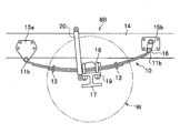
- FIG. 2 is a view showing a leaf spring for a suspension device manufactured by the method for manufacturing a spring for a suspension device according to an embodiment of the present invention.
- FIG. 2A is a side view showing a suspension device provided with a leaf spring for a suspension device
- FIG. 2B is a front view of the leaf spring for the suspension device.
- a vehicle such as a truck is provided with a suspension device 8B that suspends an axle to which wheels W are attached.
- the suspension device 8B includes a suspension leaf spring (lap leaf spring) 10 manufactured by the suspension device manufacturing method according to the present embodiment, an axle 17, and a U bolt 18. And a nut 19 and a shock absorber 20 are provided.
- the laminated leaf spring 10 is configured by a plurality of suspension device leaf springs (leaf springs) 11 being overlapped.
- the plurality of leaf springs 11 are fastened and fixed to each other by a center bolt 12 near the center of the leaf portion 11a. Further, near the end of the leaf portion 11a, the clip 13 is pinned and bundled.
- the uppermost plate spring 11 is formed with eyeballs 11b and 11b at both ends.
- a bush (not shown) having a metal outer cylinder and an inner cylinder and an elastic body that joins the outer cylinder and the inner cylinder is press-fitted into the eyeball portions 11b and 11b.
- the laminated leaf spring 10 is supported by the vehicle body frame 14 via a bush (not shown). That is, the eyeball portion 11b on one end side is pivotally attached to the bracket 15a fixed to the vehicle body frame 14, and the eyeball portion 11b on the other end side is supported by the bracket 15b fixed to the vehicle body frame 14 via the shackle 16.
- the laminated leaf spring 10 is fixed to an axle (axle beam) 17 by a U bolt 18 and a nut 19 in the leaf portion 11a.
- a shock absorber 20 is interposed between the axle 17 and the vehicle body frame 14.
- the leaf spring 11 is formed in a curved shape having a concave warp on the upper surface side.
- the leaf spring 11 elastically supports the vehicle weight in the suspension device 8B and generates a resistance force against a compressive load or a tensile load received by displacement in the direction of warpage. As a result, it plays a role of mitigating the impact applied to the vehicle body through the wheels and vibration during traveling, and also functions as a coupling mechanism.
- the overlap leaf spring 10 is a multi-leaf spring in which three leaf springs 11 having different lengths are overlapped. However, the suspension spring according to this embodiment is manufactured.
- the length, shape, number, and connection form of both ends of the leaf spring 11 to be manufactured are not particularly limited.
- the leaf spring 11 is not limited to the main spring, and may constitute an auxiliary spring.
- the width and thickness of the leaf spring 11 are appropriately set according to product specifications, but as an example, the width is about 60 mm to 100 mm and the thickness is 9 mm to 40 mm.
- suspension device spring (coil spring for suspension device, leaf spring for suspension device) according to the present embodiment.
- processes common to the suspension device coil spring and the suspension device leaf spring will be described collectively, and individual descriptions will be omitted.
- the suspension device spring according to the present embodiment is manufactured using manganese boron steel having a low carbon content as a material.
- manganese boron steel with low carbon content and excellent hardenability quenching with a medium having a heat transfer coefficient equivalent to or close to water can be adopted instead of oil quenching. Yes. That is, even if the steel material, which is a material, is quenched at a high cooling rate corresponding to water quenching, the occurrence of quenching cracks and distortion is prevented, so that the suspension spring can be manufactured with high productivity.
- a low carbon content manganese boron steel with excellent hardenability has formed a martensitic structure that has good strength (mechanical strength) and good toughness as it is quenched. .
- the manganese boron steel having a low carbon content is, in mass%, carbon (C): 0.10% to 0.39%, manganese (Mn): 1.00% to 1.50%, Boron (B): 0.0005% or more and 0.003% or less are included.
- the material for the suspension spring is obtained by subjecting the steel material obtained by hot rolling steel containing such a predetermined chemical component to wire drawing, oil tempering, patenting, etc. as necessary. Can do.
- a steel material shall be used by the meaning containing the steel materials (steel wire, steel plate, etc.) and semi-finished products in the state which processed and heat-processed.
- the carbon equivalent (Ceq) represented by: can be a chemical component composition satisfying 0.27% or more and 0.64% or less. However, in the formula, C, Mn, Cr, Mo, V, Cu, and Ni represent respective contents (mass%) when each element is included. If the carbon equivalent (Ceq) is 0.27% or more, the hardness generally required for a suspension spring can be realized.
- the carbon equivalent (Ceq) when the carbon equivalent (Ceq) is 0.64% or less, it is possible to reliably prevent the occurrence of quenching cracks even when quenching is performed at a high cooling rate corresponding to water quenching while ensuring quenching hardness. be able to. Moreover, the occurrence of delayed fracture can be significantly reduced even after quenching.
- the carbon equivalent (Ceq) is more preferably 0.36% or more and 0.41% or less.
- Manganese boron steel with a low carbon content is, by mass, C: 0.10% to 0.39%, Si: 0.05% to 0.40%, Mn: 1.00% to 1.50. % Or less, B: 0.0005% or more and 0.003% or less may be contained as an essential element, and the balance may be a chemical component composition composed of Fe, an optional additive element, or an unavoidable impurity.
- the optional additive element at least one element selected from the group consisting of Cr, Mo, V, Cu, Ni, Ti, Nb, Al, N, Ca, and Pb can be contained.
- an unavoidable impurity it is allowed to contain elements such as P and S in the range of 0.005% by mass or less.
- the manganese boron steel having a low carbon content may contain an essential element group composed of C, Si, Mn, and B, and the balance may have a chemical composition composed of Fe and inevitable impurities.
- the essential element group composed of C, Si, Mn, and B may be contained, and the balance may have a chemical composition composed of Fe, an optional additive element, and inevitable impurities. If the manganese boron steel having a low carbon content has a chemical composition that does not contain an optional additive element, the material cost of the suspension spring can be reduced.
- the chemical composition contains an arbitrarily added element, various characteristics can be modified according to the element type.
- Manganese boron steel with a low carbon content shall contain at least 1.20% of each optional additive element in the chemical composition including the optional additive element.
- Manganese boron steel having a low carbon content is a standard American Engineering standard 15B23 equivalent steel or 15B26 equivalent steel in a preferred form.
- each arbitrary addition element is contained by content with which a carbon equivalent (Ceq) satisfy
- each component element of the manganese boron steel having a low carbon content will be described.
- Carbon (C) is a component that contributes to improvement in strength and hardness.
- C Carbon (C) is a component that contributes to improvement in strength and hardness.
- C By setting C to 0.10% by mass or more, it is possible to ensure good strength and hardness required for the suspension device spring.
- C when C is 0.39% by mass or less, it is possible to prevent the occurrence of burning cracks and distortions due to transformation stress and the like, and delayed fracture. Moreover, the fall of the corrosion resistance by precipitation of a carbide
- the content of C is more preferably 0.20% by mass or more and 0.26% by mass or less.
- Silicon (Si) is a component that contributes to improvement in strength and hardness. Moreover, it is also a component added for the purpose of deoxidation at the time of steelmaking of steel materials. By setting Si to 0.05 mass% or more, good strength, hardness, corrosion resistance, and sag resistance can be ensured. On the other hand, when Si is 0.40 mass% or less, it is possible to avoid the deterioration of toughness and workability.
- the Si content is preferably 0.15% by mass or more and 0.30% by mass or less.
- Manganese (Mn) is a component that contributes to improving hardenability and strength. Moreover, it is also a component added for the purpose of deoxidation at the time of steelmaking of steel materials. By setting Mn to 1.00% by mass or more, good strength and hardenability can be ensured. On the other hand, when Mn is 1.50% by mass or less, it is possible to avoid deterioration of toughness and workability due to segregation and deterioration of corrosion resistance.
- B Boron
- B is a component that contributes to improving hardenability and strength.
- B 0.0005 mass% or more and 0.003 mass% or less good hardenability can be ensured.
- toughness and corrosion resistance can be improved by grain boundary strengthening.
- the content of B exceeds 0.003% by mass, the effect of improving the hardenability is saturated and the mechanical properties are deteriorated, so the upper limit of the content is limited.
- Phosphorus (P) is an unavoidable impurity that remains from the time of steelmaking. By making P into 0.040 mass% or less, it can avoid that toughness and corrosion resistance are impaired by segregation.
- the content of P is more preferably 0.030% by mass or less.
- S is an unavoidable impurity that remains from the time of steelmaking. By making S into 0.040 mass% or less, it can avoid that toughness and corrosion resistance are impaired by segregation or precipitation of MnS inclusions.
- the content of S is more preferably 0.030% by mass or less.
- Chromium (Cr) is a component that contributes to improving strength, corrosion resistance, and hardenability. By adding Cr, strength, corrosion resistance and hardenability can be improved. On the other hand, when Cr is excessively contained, toughness and corrosion resistance are impaired due to segregation of carbides, workability is reduced, and material costs are excessive, so the upper limit of the content is limited.
- the Cr content is preferably 1.20% by mass or less, may be 0.60% by mass or less, or a composition not intentionally added is also preferable.
- Molybdenum (Mo) is a component that contributes to improving hardenability, toughness, and corrosion resistance. By adding Mo, hardenability, toughness, and corrosion resistance can be improved. On the other hand, when Mo is excessively contained, the material cost becomes excessive, and thus the upper limit of the content is limited.
- the Mo content is preferably 0.08% by mass or less, more preferably 0.02% by mass or less, or a composition not intentionally added.
- Vanadium (V) is a component that contributes to improvements in toughness and hardness. Moreover, it has the effect
- the V content is preferably 0.30% by mass or less, or a composition not intentionally added is preferable.
- Copper (Cu) is a component that contributes to improving hardenability and corrosion resistance. By adding Cu, hardenability and corrosion resistance can be improved. However, when Cu is excessively contained, hot surface embrittlement may occur, so the upper limit of the content is limited.
- the Cu content is preferably 0.30% by mass or less, or a composition not intentionally added is preferable.
- Nickel (Ni) is a component that contributes to improving corrosion resistance and hardenability. By adding Ni, it is possible to ensure good corrosion resistance and hardenability, and it is possible to reduce corrosion deterioration and quench cracking. On the other hand, even if Ni is contained excessively, the effect of improving hardenability is saturated and the material cost also increases, so the upper limit of the content is limited.
- the Ni content is preferably 0.30% by mass or less, or a composition not intentionally added is also preferable.
- Titanium (Ti) is a component that contributes to improvement in strength and corrosion resistance. Moreover, it has the effect
- Ti when Ti is excessively contained, toughness and corrosion resistance are impaired by precipitation of carbonitrides, so the upper limit of the content is limited.
- the Ti content is preferably 0.05% by mass or less, or a composition not intentionally added is preferable.
- Niobium (Nb) is a component that contributes to improvement of strength and toughness. Moreover, it has the effect
- the Nb content is preferably 0.06% by mass or less, or a composition not intentionally added is also preferable.
- Aluminum (Al) is a component that contributes to improvement of toughness. Moreover, it has the effect
- the Al content is preferably 0.30% by mass or less, or a composition not intentionally added is preferable. Note that Al as an optional additive element corresponds to Soluble Al.
- N Nitrogen
- the N content is preferably 0.02% by mass or less.
- Calcium (Ca) is a component that contributes to improvement of machinability. By adding Ca, the machinability of the steel material can be further improved.
- the Al content is preferably 0.40% by mass or less, or a composition not intentionally added is preferable.
- Pb is a component that contributes to improvement of machinability. By adding Pb, the machinability of the steel material can be further improved.
- the Pb content is preferably 0.40% by mass or less, or a composition not intentionally added is preferable.
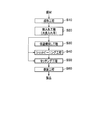
- FIG. 3 is a flowchart showing a manufacturing process of a method for manufacturing a spring for a suspension device according to an embodiment of the present invention.
- the suspension device spring manufacturing method includes a molding step S10, a quenching step S20, a low temperature tempering step S30, a shot peening step S40, a setting step S50, and a coating step S60 in this order. It can be a method comprising. In this manufacturing method, the low-temperature tempering step S30 and the shot peening step S40 are not essential steps and can be omitted as will be described later.
- the forming step S10 is a step of forming a steel material into a spring shape in a hot or cold state.
- the steel material used for forming the above-described low carbon content manganese boron steel material (steel wire, steel plate, etc.) cut into a predetermined shape according to the specifications of the suspension device spring is used.
- a steel material (steel wire) is formed in a spiral shape, and end winding portions supported by the spring seats 2a and 2b are formed at the ends.
- a steel material (steel plate) is formed into a curved shape, and the eyeball portions 11b and 11b are formed at the ends as necessary.
- the heating temperature in the hot forming is not particularly limited as long as it is an austenite region, but is preferably in the range of 850 ° C. or higher and 1100 ° C. or lower.
- the quenching step S20 is a heat treatment step in which the steel material is heat treated to austenite and then cooled at a lower critical cooling rate or higher to be quenched.
- the steel material formed into a spring shape is quenched with a medium having a heat transfer coefficient equal to or higher than that of water. It is preferable that the heat transfer coefficient of the quenching medium (coolant) is within a range of ⁇ 10% with respect to the heat transfer coefficient value of still water or water having flow with respect to the steel material.
- the heat treatment in the quenching step S20 is preferably performed at a heating temperature of 850 ° C. or higher and 1100 ° C. or lower. By suppressing the heating temperature to 1100 ° C. or less, coarsening of austenite crystal grains can be reduced. As a result, good toughness can be imparted, and the occurrence of fire cracking and distortion can also be prevented.
- a heating method for example, high frequency induction heating can be used.
- the cooling process in the quenching step S20 is performed with a medium having a heat transfer coefficient equivalent to or close to that of water. Specifically, it is preferable to perform water quenching, aqueous solution quenching or salt water quenching.
- Water quenching is a process that uses water as a coolant.
- the water temperature may be in the temperature range of 0 ° C. to 100 ° C., preferably 5 ° C. to 40 ° C.
- Aqueous solution quenching (polymer quenching) is a treatment using an aqueous solution to which a polymer is added as a coolant.
- the polymer for example, various polymers such as polyalkylene glycol and polyvinyl pyrrolidone can be used.
- Salt water quenching is a treatment using an aqueous solution to which salts such as sodium chloride are added as a coolant.
- the cooling process in the quenching step S20 may be performed by stirring the medium at an appropriate speed.
- the cooling process in the quenching step S20 may be performed in the form of restraint quenching, spray quenching, injection quenching, or the like.
- the suspension device coil spring 1 is constrained to a helical shape having a predetermined free height, and is rapidly cooled with a coolant to be martensite.
- the eyeball portions 11b and 11b at both ends are fixed and rapidly cooled with a coolant to be martensite.
- the metal structure in which the low carbon content manganese boron steel is martensitic has few precipitates and has good toughness as it is quenched. Therefore, in the manufacturing method of the suspension device spring according to the present embodiment, as shown in FIG. 3, the quenched steel material is tempered without tempering to 400 ° C. or higher, that is, the low temperature tempering step S30, shot. It shall be used for the peening process S40 or the setting process S50.
- the low temperature tempering step S30 is a heat treatment step in which the quenched steel material is soaked and tempered to 200 ° C. or higher and 350 ° C. or lower.
- the heating temperature in tempering is 200 ° C. or higher, the yield point is significantly improved by strain aging, and better strength can be imparted. Further, since dehydrogenation can be achieved, hydrogen embrittlement is reduced, and the occurrence of delayed fracture is more reliably prevented.
- the heating temperature in tempering is 350 ° C. or less, the hardness is not easily lost, and it is difficult to be affected by low temperature temper embrittlement in combination with the grain boundary strengthening by boron.
- the tempering temperature is preferably 200 ° C. or higher and 300 ° C. or lower.
- the tempering time is preferably 60 minutes or less at 300 ° C.
- the low-temperature tempering step S30 can be omitted.
- the shot peening step S40 is a step of performing shot peening on the surface of the heat-treated steel material. Shot peening may be performed in either warm or cold form, or may be performed in the form of stress peening. Further, it may be repeated a plurality of times while changing conditions such as particle diameter and projection speed. By applying shot peening, compressive residual stress can be applied to the surface of the steel material, and it is possible to prevent cracking and stress corrosion cracking, and to improve fatigue strength and wear resistance. However, the execution of the shot peening process S40 can be omitted.
- the setting step S50 is a step of applying an overload exceeding the elastic limit to the heat-treated steel material.
- the setting may be performed in either warm or cold form. As temperature conditions in warm, 200 degreeC or more and 300 degrees C or less are preferable. This is because if the temperature is 300 ° C. or lower, the compressive residual stress formed on the surface layer of the steel material is difficult to remove. By setting the working direction of the spring of the steel material formed into a spring shape, the yield point is increased and the permanent deformation is suppressed, so that the elastic limit and the sag resistance are improved.
- warm setting can be performed after the low temperature tempering step S30 and before the shot peening step S40.
- the coating step S60 is a step of coating the surface of the steel material that has been heat-treated.
- the surface of the steel material can be preliminarily subjected to a cleaning treatment or a base treatment. In the cleaning process, oil and fat on the surface and foreign matters are removed.
- a base treatment for example, a film of zinc phosphate, iron phosphate or the like is formed.
- a powder coating material such as an epoxy resin.
- the steel material to be used for coating may be preheated as necessary and then coated with a paint on the surface.
- the applied paint is then baked by furnace heating or infrared heating.
- the heating temperature in the preheating or baking is preferably in the range of 180 ° C. or more and 200 ° C. or less where normal coating can be applied.
- the suspension device spring is manufactured. Since the suspension spring is made of manganese boron steel with a low carbon content, it has both good strength and good toughness. Specifically, the metal structure of the suspension spring is a martensite structure with a main phase or a tempered martensite structure in which ⁇ carbides are precipitated, and has substantially no troostite or sorbite structure. It is also possible to manufacture a suspension spring in which 90% or more of the central portion of the cross section has a martensite structure. The as-quenched martensite structure can form a single phase extending to the center of the suspension coil spring 1 and the suspension plate spring 11 due to the hardenability of manganese boron steel having a low carbon content. Therefore, it is difficult to form a local battery between the precipitated carbide and the like, which is advantageous in that the suspension spring has excellent corrosion resistance.
- the suspension spring to be manufactured preferably has a grain size number G of more than 8 and more preferably 9 or more with respect to the grain size of the prior austenite grain boundaries.
- the refinement of the crystal grain size can be realized, for example, by lowering the quenching temperature or increasing the content of Mn or an optional additive element.
- the crystal grain size of the prior austenite grain boundaries can be measured in accordance with JIS G 0551.
- the particle size number G can be determined based on a microscope observation image of the as-quenched metal structure, and is preferably obtained as an average value of the particle size numbers of 5 to 10 fields of view.
- the quenched steel material is tempered to 400 ° C. or higher by adopting manganese boron steel having a low carbon content and excellent hardenability. It is possible to manufacture a spring for a suspension device that has both good strength and good toughness without being quenched. Therefore, there is an advantage that it is not necessary to perform high-temperature tempering in which a high amount of heat is consumed and heated to a high temperature exceeding 400 ° C. Therefore, it is possible to reduce the number of man-hours and operating costs related to the heat treatment during the manufacturing process, and the manufacturing method is suitable for downsizing the scale of the manufacturing equipment for the suspension device spring.
- the suspension device spring having both good strength and good toughness can be manufactured without being quenched, and thus the low temperature tempering step S30 is omitted. It is also possible. This is advantageous in that it is not necessary to install a long tempering furnace on the production line for the suspension device spring. Further, since tempering is not required, the number of man-hours and operating costs related to the heat treatment during the manufacturing process are reduced, and the scale of the manufacturing facility for the suspension device spring is more suitable for downsizing.
- the manufacturing method of the suspension device spring according to the present embodiment quenching with a medium having a heat transfer coefficient equal to or higher than that of water is used instead of conventional oil quenching.
- the suspension spring to be manufactured is subjected to quenching with a higher cooling rate compared to oil quenching, so that a deep distribution of compressive residual stress is applied to the surface layer as follows.
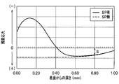
- FIG. 4 is a diagram showing the distribution of residual stress on the surface layer of the suspension spring.
- FIG. 4A is a diagram showing a distribution of residual stress in a suspension spring manufactured by water quenching
- FIG. 4B is a diagram showing a distribution of residual stress in a suspension spring manufactured by oil quenching. is there.
- the vertical axis represents the residual stress (MPa) applied to the suspension spring.
- the ( ⁇ ) side is compressive stress and the (+) side is tensile stress.
- the solid line shows the residual stress value (with SP) in the suspension spring manufactured through the shot peening process S40, and the broken line shows the residual stress value (without SP) in the suspension spring manufactured without going through the shot peening process S40. ).
- FIGS. 4A and 4B the residual stress caused by the thermal stress and the residual stress caused by the transformation stress are superimposed on the steel that has been subjected to the cooling treatment in the quenching, and a residual stress distribution appears.
- thermal contraction due to cooling of the steel material proceeds from the surface side. That is, the surface side is rapidly cooled, heat-shrinks more than the inner side, and plastically deforms while dragging the inner side. Thereafter, the deformation on the surface side ends, whereas the heat shrinkage still proceeds on the inner side where the heat conduction is delayed, and the plastic deformation ends while dragging the already solidified surface side. Therefore, the thermal stress generated in the process of such thermal shrinkage tends to have a compressive residual stress dominant on the surface side of the steel material and a tensile residual stress dominant on the inner side.
- transformation expansion due to martensitic transformation of steel also proceeds from the surface side. That is, the surface side is rapidly cooled, and is lower than the martensite transformation end temperature (Mf) before the inner side, and the volume change of the metal structure is terminated. Thereafter, the transformation on the surface side ends, whereas the transformation expansion still proceeds on the inner side where the heat conduction is delayed, and the plastic deformation ends while dragging the surface side that has already been transformed. For this reason, the transformation stress generated in the process of transformation causes a tendency that the tensile residual stress is dominant on the surface side of the steel material and the compressive residual stress is dominant on the inner side, contrary to the thermal stress.
- Mf martensite transformation end temperature
- a high cooling rate corresponding to water quenching is adopted, so that the contribution of thermal stress to transformation stress is high. Therefore, as shown by a broken line in FIG. 4A, a deep distribution of compressive residual stress is formed on the surface layer. That is, the crossing point at which the compressive residual stress changes to the tensile residual stress is at least 0.80 mm or more from the surface, and exceeds the depth of the corrosion pit that normally grows to a depth of about 0.40 mm.
- a high compressive residual stress (S) of 150 MPa or more is applied from the surface to a depth of 0.80 mm. Furthermore, when performing shot peening, as shown by a solid line in FIG. 4A, it is possible to apply a higher compressive residual stress to the surface side.
- the suspension device coil spring 1 manufactured by the suspension device manufacturing method according to the present embodiment is designed to take a desired pitch angle ( ⁇ ).
- the pitch angle ( ⁇ ) is an angle formed by a plane perpendicular to the center line (X) of the coil spring 1 and the center line (Y) of the strand.
- the pitch angle ( ⁇ ) is sufficiently small, the shear stress generated in the axial direction (X-ray direction) of the coil during use is larger than the outside of the coil ( ⁇ 1) due to the superposition of the torsional moment (N). It becomes larger on the inner side ( ⁇ 2).
- a small-diameter coil spring manufactured by cold forming tends to leave a tensile residual stress in the axial direction of the wire inside the coil due to plastic deformation in coiling. From such a characteristic, it is desired that a sufficient compressive residual stress be applied to the inside of the coil from the viewpoint of appropriately preventing fatigue failure occurring in the coil spring 1.
- a compressive residual stress having a deep distribution is easily formed over the entire surface layer of the coil spring 1 through quenching at a high cooling rate corresponding to water quenching. It is possible to make it. Therefore, the fatigue durability of the coil spring 1 can be improved, and the occurrence of delayed fracture such as cracking can be prevented. In particular, it is advantageous in that fatigue fracture starting from the inside of the coil can be satisfactorily prevented. Further, the omission of the shot peening step S40 can be permitted by applying a deep distribution of high compressive residual stress.
- the inside of the coil of the coil spring 1 is a region where it is difficult for the shot peening projection material to reach compared to the outside of the coil.
- the inner side of the coil of the coil spring 1 is not affected by shot peening by quenching at a high cooling rate corresponding to water quenching. It is possible to have the same hardness as the outside.
- the inner side and the outer side of the coil mean an inner region and an outer region of a plane that is parallel to the axial direction of the coil and passes through the center of the wire.
- the coil spring 1 for a suspension device has the same hardness ( ⁇ 5% HV) on the inner side and the outer side of the coil when shot peening is not performed by such a manufacturing method.
- a compressive residual stress 150 MPa or more from the surface to a depth of 0.80 mm both inside and outside the coil.
- the Charpy impact value at room temperature can be 30 J / cm 2 or more in the generally required hardness. Since the crossing point is at least 0.80 mm deep from the surface, cracks caused by corrosion pits can be satisfactorily prevented even in the case winding portion where the coating or the like easily peels off due to sliding or collision with the spring seat. This is advantageous in that it can.
- the suspension device leaf spring 11 manufactured by the suspension device manufacturing method according to the present embodiment has a vehicle body via eyeballs 11b and 11b formed at both ends. Supported by the frame 14. It is known that the inner peripheral surface 110 of the eyeball portion 11b where loads from the vehicle body side tend to concentrate tends to be a starting point for delayed fracture and fatigue fracture. From such a characteristic, it is desired that sufficient compressive residual stress is applied to the inner peripheral surface 110 of the eyeball portion 11b from the viewpoint of appropriately preventing fatigue failure occurring in the leaf spring 11.
- the inner peripheral surface 110 of the center part 11b of the leaf spring 11 is an area that requires man-hours to reach the shot peening projection material, as compared with the leaf part 11a.
- the leaf spring 11 has a substantially rectangular cross-sectional shape, and has a shape in which uniform shot peening is relatively difficult including corners.
- the inner peripheral surface 110 of the eyeball portion 11b of the leaf spring 11 is equivalent to the leaf portion 11a by quenching at a fast cooling rate corresponding to water quenching. It is advantageous in that it can be made hard, and a compressive residual stress can be reliably applied to the corners in a cross-sectional view.
- the suspension device leaf spring 11 is obtained by such a manufacturing method, in a state where shot peening has not been performed, and the warped side surface of the leaf portion 11a and the inner peripheral surface 110 of the eyeball portion 11b.
- the Charpy impact value at room temperature can be 30 J / cm 2 or more in the generally required hardness. Since the crossing point has a depth of at least 0.80 mm from the surface, it is advantageous in that the crossing point is resistant to defects caused by sliding and collision of the stacked leaf springs 11 and the center bolt 12.
- the type of medium is not particularly limited.
- it may be water or oil containing ice, an organic solvent, a liquid or solid having a high heat transfer coefficient.
- the phase of the medium is not particularly limited, such as a liquid or a liquid containing a solid.
- each configuration may be selected, or each configuration may be appropriately selected and combined.
Landscapes
- Chemical & Material Sciences (AREA)
- Engineering & Computer Science (AREA)
- Mechanical Engineering (AREA)
- Organic Chemistry (AREA)
- Materials Engineering (AREA)
- Metallurgy (AREA)
- General Engineering & Computer Science (AREA)
- Physics & Mathematics (AREA)
- Thermal Sciences (AREA)
- Crystallography & Structural Chemistry (AREA)
- Heat Treatment Of Articles (AREA)
- Vehicle Body Suspensions (AREA)
- Springs (AREA)
Abstract
本発明の懸架装置用ばねの製造方法は、質量%で、C:0.10%以上0.39%以下、Mn:1.00%以上1.50%以下、B:0.0005%以上0.003%以下を含む鋼材を熱間又は冷間においてばね形状に成形する成形工程S10と、成形された前記鋼材に水と同等以上又は水に近い熱伝達率を有する媒体による焼入れを施す焼入れ工程S20とを含み、焼入れが施された前記鋼材を400℃以上に焼戻すこと無く懸架装置用ばねを製造することを特徴とする。
Description
本発明は、懸架装置用ばねの製造方法及び懸架装置用ばねに関する。
自動車等の車両においては、車軸を懸架する懸架装置にコイルばねや板ばね(重ね板ばね)等の懸架装置用ばねが備えられている。懸架装置用ばねは、車体側と車輪側とを連結して車重を支持し、車輪を伝って車体に及ぼされる衝撃を緩衝する役割等を担っている。懸架装置の分野においては、従来から、車重の軽量化の要求に対応した軽量の懸架装置用ばねが求められている。加えて、近年では、電動モータや二次電池の搭載に伴って車重が重量化する傾向も生じている。そのため、高応力に対応しており、軽量化を実現し得る懸架装置用ばねが望まれている。
従来、懸架装置用ばねの材料としては、SUP9、SUP9A、SUP11A(JIS規格)をはじめとするばね鋼等が用いられてきた。懸架装置用ばねは、所定形状寸法に加工した鋼線や鋼板を熱間又は冷間においてばね形状に成形し、熱処理を経て製造されている。熱処理としては、多くの場合、油焼入れと焼戻しとが実施されている。懸架装置用ばねは、このような熱処理の後、ショットピーニング、セッチング、塗装処理等を経て製品化されている。
このように調質を経て懸架装置用ばねを製造する技術としては、例えば、特許文献1に、重量%で(以下、同じ)、C:0.30~0.75%、Si:1.0~4.0%、Mn:0.5~1.5%、Cr:0.1~2.0%及びNi≦2.0%を含み、残部がFe及び不可避的不純物からなる鋼について、油焼入れを施し、油焼入れ後の残留オーステナイトの発生量を10%未満にしたうえで、焼きもどしを施する疲労強度、耐へたり性に優れた高強度ばね用鋼の製造方法が開示されている。
特許文献1に開示されているように、高強度鋼で懸架装置用ばねを製造するにあたっては、焼割れを回避するために一般に油焼入れが実施されている。しかしながら、油焼入れを経る製造方法は、安全性や環境適合性の観点からは必ずしも最適な方法ではない。油焼入れにおいて使用される鉱油等の冷却剤は発火の危険性があり、取り扱い、保管、製造設備設計等について制約が生じるためである。また、使用後の廃油の環境負荷も低くないため、廃棄経費等が嵩む場合があり得る。すなわち、油焼入れを経る製造方法は、懸架装置用ばねの生産性を低下させる要因を少なからず抱えるものとなっている。
また、懸架装置用ばねは、機械的強度と共に良好な靭性を兼ね備え、疲労耐久性に優れることが望まれる。従来は、高応力設計に対応しつつ十分な疲労耐久性を与えるために、焼入れ後に高温焼戻しが実施されることが多かった。一方で、近年では、戦略的に生産拠点を新設・移設する車両メーカの近くで懸架装置用ばねの製造を行う要求が高く、製造設備規模、工数、運転経費等が削減されたコンパクトな製造ラインが望まれている現状もある。高温焼戻しは、通常、400℃程度を超える高温への加熱処理を伴い、こうした加熱処理が複数回に及ぶこともあるため、既に焼入れが施された鋼材に対して、追加的に多大な熱量と時間とを費やすことを要している。それ故、高温焼戻しを経る懸架装置用ばねの製造方法は、昨今の製造ラインのコンパクト化の要求にそぐわないものとなっている。
そこで、本発明は、良好な機械的強度と靭性とを有する懸架装置用ばねを、コンパクトな生産ラインで生産性高く製造できる懸架装置用ばねの製造方法及びその製造方法によって製造される懸架装置用ばねを提供することを目的とする。
前記課題を解決するために、本発明に係る懸架装置用ばねの製造方法は、質量%で、C:0.10%以上0.39%以下、Mn:1.00%以上1.50%以下、B:0.0005%以上0.003%以下を含む鋼材を熱間又は冷間においてばね形状に成形する成形工程と、成形された前記鋼材に水と同等以上又は水に近い熱伝達率を有する媒体による焼入れを施す焼入れ工程とを含み、焼入れが施された前記鋼材を400℃以上に焼戻すこと無く懸架装置用ばねを製造することを特徴とする。
また、本発明に係る懸架装置用ばねは、前記の懸架装置用ばねの製造方法によって製造されることを特徴とする。
本発明によれば、良好な機械的強度と靭性とを有する懸架装置用ばねを、コンパクトな生産ラインで生産性高く製造できる懸架装置用ばねの製造方法を提供することができる。その製造方法によって製造される懸架装置用ばねは、表層に深い分布の高い圧縮残留応力が付与されているため、遅れ破壊を生じ難く、疲労耐久性が良好である。
以下、本発明の一実施形態に係る懸架装置用ばねの製造方法及びその製造方法によって製造される懸架装置用ばねについて説明する。なお、各図において共通する構成要素については、同一の符号を付し、重複した説明を省略する。
本実施形態に係る懸架装置用ばねの製造方法は、車両に設けられる懸架装置に備えられるコイルばね(懸架装置用コイルばね)や、重ね板ばねを構成する板ばね(懸架装置用板ばね)等の懸架装置用ばねの製造方法に関する。この製造方法は、素材を熱間又は冷間においてばね形状に成形し、水と同等以上又は水に近い熱伝達率を有する媒体による焼入れを施し、焼入れが施された鋼材を焼入れ後に400℃以上に焼戻すこと無く懸架装置用ばねを製造する方法となっている。懸架装置用ばねの材料としては、特に低炭素含有量のマンガンボロン鋼が採用されたものである。
[懸架装置用コイルばね]
はじめに、本実施形態に係る懸架装置用ばねの製造方法によって製造される懸架装置用コイルばねについて説明する。
はじめに、本実施形態に係る懸架装置用ばねの製造方法によって製造される懸架装置用コイルばねについて説明する。
図1は、本発明の一実施形態に係る懸架装置用ばねの製造方法によって製造される懸架装置用コイルばねを示す図である。図1Aは、懸架装置用コイルばねが備えられた懸架装置を示す斜視図、図1Bは、懸架装置用コイルばねの縦断面図である。
図1Aに示すように、車両には、車輪Wが取り付けられる車軸を懸架する懸架装置8Aが備えられる。図1Aでは、懸架装置として、左右が独立したストラット式の懸架装置8A,8Aが示されている。図1Aに示すように、左右一対の懸架装置8A,8Aには、本実施形態に係る懸架装置用ばねの製造方法によって製造される懸架装置用コイルばね(コイルばね)1と、ばね座2aと、ばね座2bと、ショックアブソーバ3とがそれぞれ備えられている。
ショックアブソーバ3は、筒状のシリンダ、シリンダに挿入されたロッド、オリフィス等によって構成される減衰力発生機構等を有している。ロッドの一端にはピストンが備えられ、ロッドの伸縮によってシリンダの内部の作動流体が流動し、流動に伴う抵抗によって減衰力が発生するようになっている。ショックアブソーバ3の一端はブラケット5を介してナックル6に支持され、他端は不図示の車体側に連結される。図1Aに示すように、ショックアブソーバ3のシリンダには、ばね座2aが固定されており、他端にはばね座2bが固定されている。そして、ばね座2aとばね座2bとの間に、コイルばね1が介装されている。
図1Bに示すように、コイルばね1は、断面が円形の素線が螺旋形状に成形されてなる。コイルばね1は、懸架装置8Aにおいて車重を弾性的に支持すると共に、軸方向に受ける圧縮荷重や引張荷重に対して抵抗力を生じさせる。これによって、車輪を伝って車体に及ぼされる衝撃や走行中の振動を緩和する役割を担う。なお、本実施形態に係る懸架装置用ばねの製造方法においては、製造されるコイルばね1のコイル平均径、ピッチ、ばね定数、巻方向等は特に制限されない。また、図1Bにおいては、円筒形コイルが示されているが、コイルばね1の形状は、たる形、鼓形等の適宜の形状であってよい。コイルばね1の素線の径は、製品の仕様に応じて適宜設定されるが、一例として凡そ8mm以上21mm以下の範囲である。なお、後記するとおり、図1Bに示すNは、ねじりモーメント、τ1及びτ2は、せん断応力を示している。
[懸架装置用板ばね]
続いて、本実施形態に係る懸架装置用ばねの製造方法によって製造される懸架装置用板ばねについて説明する。
続いて、本実施形態に係る懸架装置用ばねの製造方法によって製造される懸架装置用板ばねについて説明する。
図2は、本発明の一実施形態に係る懸架装置用ばねの製造方法によって製造される懸架装置用板ばねを示す図である。図2Aは、懸架装置用板ばねが備えられた懸架装置を示す側面図、図2Bは、懸架装置用板ばねの正面図である。
図2Aに示すように、トラック等の車両には、車輪Wが取り付けられる車軸を懸架する懸架装置8Bが備えられる。図2Aでは、車両の左右に備えられる一対のリーフ式懸架装置8Bの一方のみが示されている。図2Aに示すように、懸架装置8Bには、本実施形態に係る懸架装置用ばねの製造方法によって製造される懸架装置用重ね板ばね(重ね板ばね)10と、アクスル17と、Uボルト18と、ナット19と、ショックアブソーバ20とがそれぞれ備えられている。
図2Bに示すように、重ね板ばね10は、複数の懸架装置用板ばね(板ばね)11が重ね合わされて構成されている。複数の板ばね11は、リーフ部11aの中央付近においては、センタボルト12によって互いに締結固定されている。また、リーフ部11aの端部寄りにおいては、クリップ13によってピン止めされて束ねられている。そして、最上段の板ばね11には、両端部に目玉部11b,11bが形成されている。これら目玉部11b,11bには、金属製の外筒及び内筒と、外筒と内筒との間を接合する弾性体とを有する不図示のブッシュが圧入される。
図2Aに示すように、重ね板ばね10は、不図示のブッシュを介して車体フレーム14に支持される。すなわち、一端側の目玉部11bは、車体フレーム14に固定されたブラケット15aに枢着され、他端側の目玉部11bは、シャックル16を介して車体フレーム14に固定されたブラケット15bに支持される。一方、重ね板ばね10は、リーフ部11aにおいて、Uボルト18とナット19とによってアクスル(アクスルビーム)17に固定される。そして、アクスル17と車体フレーム14との間にはショックアブソーバ20が介装されている。
板ばね11は、図2A及び図2Bに示すように、上面側に凹状の反りを持った湾曲形状に成形されている。板ばね11は、懸架装置8Bにおいて車重を弾性的に支持すると共に、反りの方向の変位により受ける圧縮荷重や引張荷重に対して抵抗力を生じさせる。これによって、車輪を伝って車体に及ぼされる衝撃や走行中の振動を緩和する役割を担うと共に連結機構として機能する。なお、重ね板ばね10は、図2A及び図2Bにおいては、長さが異なる3枚の板ばね11が重ね合わされたマルチリーフスプリングとされているが、本実施形態に係る懸架装置用ばねの製造方法においては、製造される板ばね11の長さ、形状、枚数、両端部の連結形式は特に制限されない。また、板ばね11としては、主ばねに限られず、補助ばねを構成するものであってもよい。板ばね11の幅や厚さは、製品の仕様に応じて適宜設定されるが、一例として凡そ幅60mm以上100mm以下、厚さ9mm以上40mm以下の範囲である。
[懸架装置用ばねの製造方法]
次に、本実施形態に係る懸架装置用ばね(懸架装置用コイルばね、懸架装置用板ばね)の製造方法について説明する。なお、以下の説明では、懸架装置用コイルばねと懸架装置用板ばねとにおいて共通する工程については一括して説明し、個別の説明を省略する。
次に、本実施形態に係る懸架装置用ばね(懸架装置用コイルばね、懸架装置用板ばね)の製造方法について説明する。なお、以下の説明では、懸架装置用コイルばねと懸架装置用板ばねとにおいて共通する工程については一括して説明し、個別の説明を省略する。
本実施形態に係る懸架装置用ばねは、低炭素含有量のマンガンボロン鋼を材料として製造される。焼入れ性に優れた低炭素含有量のマンガンボロン鋼が採用されることで、油焼入れに代えて、水と同等以上又は水に近い熱伝達率を有する媒体による焼入れが採用され得るようになっている。すなわち、材料である鋼材に水焼入れに相当する速い冷却速度で焼入れを施しても焼割れや歪の発生が阻止されるため、生産性良く懸架装置用ばねの製造が可能となっている。加えて、焼入れ性に優れた低炭素含有量のマンガンボロン鋼によって、良好な強度(機械的強度)と共に良好な靭性を兼ね備えたマルテンサイト組織が、焼き入れままで形成されるようになっている。
低炭素含有量のマンガンボロン鋼は、詳細には、質量%で、炭素(C):0.10%以上0.39%以下、マンガン(Mn):1.00%以上1.50%以下、ボロン(B):0.0005%以上0.003%以下を含んでいる。懸架装置用ばねの素材は、このような所定の化学成分を含む鋼を熱間圧延して得た鋼材に、必要に応じて伸線加工、オイルテンパ処理、パテンチング処理等を施すことによって得ることができる。なお、本明細書においては、鋼材は、加工や熱処理が施された状態の鋼材(鋼線、鋼板など)や半製品を含む意味で用いるものとする。
低炭素含有量のマンガンボロン鋼は、次の数式:
Ceq(IIW)=C+Mn/6+(Cr+Mo+V)/5+(Cu+Ni)/15
:で表される炭素当量(Ceq)が0.27%以上0.64%以下を満たす化学成分組成とすることができる。但し、数式中、C、Mn、Cr、Mo、V、Cu及びNiは、それぞれ各元素が含まれる場合の各含有量(質量%)を表す。炭素当量(Ceq)が0.27%以上であれば、懸架装置用ばねに一般に求められる硬さを実現することができる。一方、炭素当量(Ceq)が0.64%以下であると、焼入れ硬さを確保しつつ、水焼入れに相当する速い冷却速度で焼入れが施されたとしても焼割れの発生を確実に阻止することができる。また、焼入れ後においても遅れ破壊の発生を顕著に低減させることができる。炭素当量(Ceq)は、より好ましくは0.36%以上0.41%以下である。
Ceq(IIW)=C+Mn/6+(Cr+Mo+V)/5+(Cu+Ni)/15
:で表される炭素当量(Ceq)が0.27%以上0.64%以下を満たす化学成分組成とすることができる。但し、数式中、C、Mn、Cr、Mo、V、Cu及びNiは、それぞれ各元素が含まれる場合の各含有量(質量%)を表す。炭素当量(Ceq)が0.27%以上であれば、懸架装置用ばねに一般に求められる硬さを実現することができる。一方、炭素当量(Ceq)が0.64%以下であると、焼入れ硬さを確保しつつ、水焼入れに相当する速い冷却速度で焼入れが施されたとしても焼割れの発生を確実に阻止することができる。また、焼入れ後においても遅れ破壊の発生を顕著に低減させることができる。炭素当量(Ceq)は、より好ましくは0.36%以上0.41%以下である。
低炭素含有量のマンガンボロン鋼は、質量%で、C:0.10%以上0.39%以下、Si:0.05%以上0.40%以下、Mn:1.00%以上1.50%以下、B:0.0005%以上0.003%以下を必須元素として含有し、残部がFeと、任意添加元素や不可避的不純物とで組成される化学成分組成とすることもできる。任意添加元素としては、Cr、Mo、V、Cu、Ni、Ti、Nb、Al、N、Ca及びPbからなる群より選択される少なくとも一種以上の元素を含有することができる。不可避的不純物としては、P、S等の元素を0.005質量%以下の範囲で含有することが許容される。
低炭素含有量のマンガンボロン鋼は、より具体的には、C、Si、Mn及びBからなる必須元素群を含有し、残部がFeと不可避的不純物とからなる化学組成を有するものとしてもよいし、C、Si、Mn及びBからなる必須元素群を含有し、残部がFeと任意添加元素と不可避的不純物とからなる化学組成を有するものとしてもよい。低炭素含有量のマンガンボロン鋼を任意添加元素を含有しない化学組成とすると、懸架装置用ばねの材料費を低廉にすることができる。一方、任意添加元素を含有する化学組成とすると、元素種類に応じて諸特性を改質することが可能になる。
低炭素含有量のマンガンボロン鋼は、任意添加元素を含む化学組成においては、各任意添加元素のそれぞれを少なくとも1.20%以下の範囲となるように含むものとする。低炭素含有量のマンガンボロン鋼は、好ましい形態ではStandard American Engineering 規格の15B23相当鋼ないし15B26相当鋼である。なお、各任意添加元素は、炭素当量(Ceq)が前記の数値範囲を満たす含有量で含まれることが好ましいが、前記の数値範囲を満たさない含有量で含まれることも妨げられない。以下、低炭素含有量のマンガンボロン鋼の各成分元素について説明する。
炭素(C)は、強度や硬さの向上等に寄与する成分である。Cを0.10質量%以上とすることで、懸架装置用ばねに求められる良好な強度や硬さを確保することができる。一方で、Cを0.39質量%以下とすると、変態応力等に起因する焼割れや歪の発生、遅れ破壊を阻止することができる。また、炭化物の析出による耐食性の低下を抑制することができる。Cの含有量は、より好ましくは0.20質量%以上0.26質量%以下である。
ケイ素(Si)は、強度や硬さの向上等に寄与する成分である。また、鋼材の製鋼時に脱酸の目的で添加される成分でもある。Siを0.05質量%以上とすることで、良好な強度や硬さ、耐食性、耐へたり性を確保することができる。一方で、Siを0.40質量%以下とすると、靭性や加工性が損なわれるのを避けることができる。Siの含有量は、好ましくは0.15質量%以上0.30質量%以下である。
マンガン(Mn)は、焼入れ性や強度の向上等に寄与する成分である。また、鋼材の製鋼時に脱酸の目的で添加される成分でもある。Mnを1.00質量%以上とすることで、良好な強度と焼入れ性とを確保することができる。一方で、Mnを1.50質量%以下とすると、偏析によって靭性や加工性が損なわれたり、耐食性が低下するのを避けることができる。
ホウ素(B;Boron)は、焼入れ性や強度の向上等に寄与する成分である。Bを0.0005質量%以上0.003質量%以下とすることで、良好な焼入れ性を確保することができる。また、粒界強化によって靭性や耐食性を向上させることができる。一方で、Bを0.003質量%を超える含有量としても、焼入れ性の向上の効果は飽和し、機械的性質は悪化してしまうため、含有量の上限を制限する。
リン(P)は、鋼材の製鋼時から残留する不可避的不純物である。Pを0.040質量%以下とすることで、偏析によって靭性や耐食性が損なわれるのを避けることができる。Pの含有量は、より好ましくは0.030質量%以下である。
硫黄(S)は、鋼材の製鋼時から残留する不可避的不純物である。Sを0.040質量%以下とすることで、偏析やMnS系介在物の析出によって靭性や耐食性が損なわれるのを避けることができる。Sの含有量は、より好ましくは0.030質量%以下である。
クロム(Cr)は、強度や耐食性や焼入れ性の向上等に寄与する成分である。Crを添加することで、強度や耐食性や焼入れ性を向上させることができる。一方で、Crを過剰に含有させると、炭化物の偏析によって靭性や耐食性が損なわれたり、加工性が低下したり、材料コストが過大になったりするため、含有量の上限を制限する。Crの含有量は、1.20質量%以下とすることが好ましく、0.60質量%以下としてもよく、或いは、意図的に添加しない組成とすることも好ましい。
モリブデン(Mo)は、焼入れ性や靭性や耐食性の向上等に寄与する成分である。Moを添加することで、焼入れ性や靭性や耐食性を向上させることができる。一方で、Moを過剰に含有させると、材料コストが過大になってしまうため、含有量の上限を制限する。Moの含有量は、0.08質量%以下とすることが好ましく、0.02質量%以下とすることがより好ましく、或いは、意図的に添加しない組成とすることも好ましい。
バナジウム(V)は、靭性や硬さの向上等に寄与する成分である。また、窒素(N)と結合してNによるホウ素(B)の固定を防止する作用を有している。Vを添加することで、靭性や硬さやを向上させたり、ホウ素(B)による効果を有効に発現させたりすることができる。一方で、Vを過剰に含有させると、炭窒化物の析出によって靭性や耐食性が損なわれたり、材料コストが過大になったりするため、含有量の上限を制限する。Vの含有量は、0.30質量%以下とすることが好ましく、或いは、意図的に添加しない組成とすることも好ましい。
銅(Cu)は、焼入れ性や耐食性の向上等に寄与する成分である。Cuを添加することで、焼入れ性や耐食性を向上させることができる。但し、Cuを過剰に含有させると、熱間での表面脆化が生じる場合があるため、含有量の上限を制限する。Cuの含有量は、0.30質量%以下とすることが好ましく、或いは、意図的に添加しない組成とすることも好ましい。
ニッケル(Ni)は、耐食性や焼入れ性の向上等に寄与する成分である。Niを添加することで、良好な耐食性や焼入れ性を確保することができ、腐食劣化や焼割れの低減を図ることが可能である。一方で、Niを過剰に含有させても、焼入れ性の向上の効果は飽和し、材料コストも増大してしまうため、含有量の上限を制限する。Niの含有量は、0.30質量%以下とすることが好ましく、或いは、意図的に添加しない組成とすることも好ましい。
チタン(Ti)は、強度や耐食性の向上等に寄与する成分である。また、窒素(N)と結合してNによるホウ素(B)の固定を防止する作用を有している。Tiを添加することで、強度や耐食性を向上させたり、ホウ素(B)による効果を有効に発現させたりすることができる。一方で、Tiを過剰に含有させると、炭窒化物の析出によって靭性や耐食性が損なわれるため、含有量の上限を制限する。Tiの含有量は、0.05質量%以下とすることが好ましく、或いは、意図的に添加しない組成とすることも好ましい。
ニオブ(Nb)は、強度や靭性の向上等に寄与する成分である。また、窒素(N)と結合してNによるホウ素(B)の固定を防止する作用を有している。Nbを添加することで、結晶粒の微小化によって強度や靭性を向上させたり、ホウ素(B)による効果を有効に発現させたりすることができる。一方で、Nbを過剰に含有させると、炭窒化物の析出によって靭性や耐食性が損なわれるため、含有量の上限を制限する。Nbの含有量は、0.06質量%以下とすることが好ましく、或いは、意図的に添加しない組成とすることも好ましい。
アルミニウム(Al)は、靭性の向上等に寄与する成分である。また、窒素(N)と結合してNによるホウ素(B)の固定を防止する作用を有している。また、鋼材の製鋼時に脱酸の目的で添加される成分でもある。Alを添加することで、結晶粒の微小化によって強度や靭性を向上させたり、ホウ素(B)による効果を有効に発現させたりすることができる。一方で、Alを過剰に含有させると、窒化物や酸化物の析出によって靭性や耐食性が損なわれるため、含有量の上限を制限する。Alの含有量は、0.30質量%以下とすることが好ましく、或いは、意図的に添加しない組成とすることも好ましい。なお、任意添加元素としてのAlは、Soluble Alに相当するものとする。
窒素(N)は、鋼材の製鋼時から残留する不可避的不純物である。但し、強度の向上等に寄与する成分であるため、意図的に添加することもできる。Nを所定含有量の範囲で含有させることで、窒化物の析出によって靭性や耐食性が損なわれるのを避けつつ強度を向上させることが可能である。Nの含有量は、0.02質量%以下とすることが好ましい。
カルシウム(Ca)は、被削性の向上等に寄与する成分である。Caを添加することで、鋼材の被削性をより向上させることができる。Alの含有量は、0.40質量%以下とすることが好ましく、或いは、意図的に添加しない組成とすることも好ましい。
鉛(Pb)は、被削性の向上等に寄与する成分である。Pbを添加することで、鋼材の被削性をより向上させることができる。Pbの含有量は、0.40質量%以下とすることが好ましく、或いは、意図的に添加しない組成とすることも好ましい。
図3は、本発明の一実施形態に係る懸架装置用ばねの製造方法の製造工程を示す流れ図である。
図3に示すように、懸架装置用ばねの製造方法は、成形工程S10と、焼入れ工程S20と、低温焼戻し工程S30と、ショットピーニング工程S40と、セッチング工程S50と、塗装工程S60とをこの順に含んでなる方法とすることができる。なお、この製造方法において、低温焼戻し工程S30と、ショットピーニング工程S40とは、必須の工程ではなく、後記するように実施を省略することも可能である。
成形工程S10は、鋼材を熱間又は冷間においてばね形状に成形する工程である。成形に供する鋼材としては、懸架装置用ばねの仕様に応じて所定形状寸法に断裁された前記の低炭素含有量のマンガンボロン鋼の鋼材(鋼線、鋼板など)を用いる。具体的には、懸架装置用コイルばね1にあっては、鋼材(鋼線)を螺旋形状に成形し、末端にばね座2a,2bに支持される座巻部を形成する。また、懸架装置用板ばね11にあっては、鋼材(鋼板)を湾曲形状に成形し、必要に応じて末端に目玉部11b,11bを形成する。熱間成形における加熱温度は、オーステナイト域であれば特に制限されるものではないが、好ましくは850℃以上1100℃以下の範囲である。
焼入れ工程S20は、鋼材を加熱処理してオーステナイト化した後に下部臨界冷却速度以上で冷却処理して焼入れを施す熱処理の工程である。詳細には、本実施形態に係る懸架装置用ばねの製造方法においては、ばね形状に成形された鋼材に水と同等以上又は水に近い熱伝達率を有する媒体による焼入れを施すものとしている。焼入れ媒体(冷却剤)の熱伝達率は、鋼材に対する静止した水ないし流れを有する水の熱伝達率値に対して±10%以内の範囲であることが好ましい。
焼入れ工程S20における加熱処理は、加熱温度を850℃以上1100℃以下とすることが好ましい。加熱温度を1100℃以下に抑えることによって、オーステナイト結晶粒の粗大化を低減させることができる。その結果、良好な靭性を付与することができ、焼割れや歪の発生も阻止することができる。加熱方法としては、例えば、高周波誘導加熱を用いることができる。成形工程S10において熱間成形を行う場合には、オーステナイト化させた鋼材を成形後に直ちに冷却処理に供して焼入れを施してもよい。
焼入れ工程S20における冷却処理は、水と同等以上又は水に近い熱伝達率を有する媒体により行う。具体的には、水焼入れ、水溶液焼入れ又は塩水焼入れを施すことが好ましい。水焼入れは、冷却剤として、水を用いる処理である。水温は、0℃以上100℃以下程度、好ましくは5℃以上40℃以下の温度範囲とすればよい。水溶液焼入れ(ポリマー焼入れ)は、冷却剤として、高分子を添加した水溶液を用いる処理である。高分子としては、例えば、ポリアルキレングリコール、ポリビニルピロリドン等の各種の高分子を用いることができる。塩水焼入れは、冷却剤として、塩化ナトリウム等の塩類を添加した水溶液を用いる処理である。焼入れ工程S20における冷却処理は、媒体を適宜の速度で撹拌して行えばよい。
焼入れ工程S20における冷却処理は、拘束焼入れ、噴霧焼入れ、噴射焼入れ等の形態で行ってもよい。具体的には、懸架装置用コイルばね1にあっては、所定の自由高さの螺旋形状に拘束し、冷却剤により急冷してマルテンサイト化させる。また、懸架装置用板ばね11にあっては、両端の目玉部11b,11bを固定し、冷却剤により急冷してマルテンサイト化させる。低炭素含有量のマンガンボロン鋼がマルテンサイト化した金属組織は、析出物が少なく、焼入れままで良好な靭性を有している。そこで、本実施形態に係る懸架装置用ばねの製造方法においては、図3に示すように、焼入れが施された鋼材を400℃以上に焼戻すこと無く後工程、すなわち、低温焼戻し工程S30、ショットピーニング工程S40又はセッチング工程S50に供するものとする。
低温焼戻し工程S30は、焼入れが施された鋼材を200℃以上350℃以下に均熱して焼戻しを施す熱処理の工程である。焼戻しにおける加熱温度が200℃以上であると、ひずみ時効により有意に降伏点が向上し、より良好な強度を付与することができる。また、脱水素を図ることができるため、水素脆化が低減し、遅れ破壊の発生がより確実に阻止される。一方、焼戻しにおける加熱温度が350℃以下であれば、硬さが損なわれ難く、ホウ素による粒界強化と相俟って低温焼戻し脆化の影響を受け難くなる。焼戻し温度は、好ましくは200℃以上300℃以下である。焼戻し時間は、300℃において60分以下とすることが好ましい。但し、低温焼戻し工程S30は、実施を省略化することも可能である。
ショットピーニング工程S40は、熱処理が施された鋼材の表面にショットピーニングを施す工程である。ショットピーニングは、温間及び冷間のいずれの形態で行ってもよいし、ストレスピーニングの形態で行ってもよい。また、粒子径や投射速度等の条件を変えて複数回繰り返し行ってもよい。ショットピーニングを施すことによって、鋼材の表面に圧縮残留応力を付加することができ、置割れや応力腐食割れ等の発生の阻止や、疲労強度や耐摩耗性の向上を図ることができる。但し、ショットピーニング工程S40は、実施を省略化することも可能である。
セッチング工程S50は、熱処理が施された鋼材に弾性限以上の過荷重を負荷する工程である。セッチングは、温間及び冷間のいずれの形態で行ってもよい。温間における温度条件としては、200℃以上300℃以下が好ましい。温度が300℃以下であれば、鋼材の表層に形成された圧縮残留応力が除去され難いためである。ばね形状に成形された鋼材のばねの作用方向にセッチングを施すことによって、降伏点が高められ、永久変形が抑制されることにより弾性限や耐へたり性の向上が図られる。なお、このセッチング工程S50に加えて、低温焼戻し工程S30の後、且つ、ショットピーニング工程S40の前に温間でセッチング(ホットセッチング)を施すこともできる。
塗装工程S60は、熱処理が施された鋼材の表面を塗装する工程である。塗装にあたっては、鋼材の表面にあらかじめ洗浄処理や下地処理を施すことができる。洗浄処理では、表面の油脂分や異物等を除去する。また、下地処理では、例えば、リン酸亜鉛、リン酸鉄等の被膜を形成する。塗装には、エポキシ樹脂製等の粉体塗料を用いることが好ましい。塗装に供する鋼材は、必要に応じて予加熱した後に表面に塗料を塗着させてよい。そして、塗着させた塗料を炉加熱や赤外線加熱により焼き付けることで塗装を行う。予加熱や焼き付けにおける加熱温度は、通常の塗料の塗着が可能な180℃以上200℃以下の範囲とすることが好ましい。
以上の製造工程や製品検査等を経て、懸架装置用ばねが製造される。懸架装置用ばねは、低炭素含有量のマンガンボロン鋼を材料としているため、良好な強度と良好な靭性とを兼ね備えている。具体的には、懸架装置用ばねの金属組織は、主相がマルテンサイト組織又はε炭化物が析出した焼戻しマルテンサイト組織となり、トルースタイトやソルバイトの組織を実質的に有さないものとなる。横断面の中心部分の90%以上がマルテンサイト組織を有する懸架装置用ばねの製造も可能である。焼入れままのマルテンサイト組織は、低炭素含有量のマンガンボロン鋼の焼入れ性により、懸架装置用コイルばね1や懸架装置用板ばね11の中心部に及ぶ単相を形成し得る。そのため、析出した炭化物等との間で局部電池が形成され難く、耐食性に優れた懸架装置用ばねとなる点で有利である。
製造される懸架装置用ばねは、旧オーステナイト結晶粒界の結晶粒度について粒度番号Gが8を超えるようにすることが好ましく、9以上にすることがより好ましい。旧オーステナイト結晶粒界の結晶粒度をこのように微細化することにより、靭性を損なわず強度をより向上させることができる。結晶粒度の微細化は、例えば、焼入れ温度を低下させたり、Mnや任意添加元素の含有量を高めたりすることによって実現することが可能である。なお、旧オーステナイト結晶粒界の結晶粒度は、JIS G 0551の規定に準じて測定することができる。粒度番号Gは、焼き入れままの金属組織の顕微鏡観察像に基いて判定することができ、望ましくは5~10視野の粒度番号の平均値として求められる。
以上の本実施形態に係る懸架装置用ばねの製造方法によると、焼入れ性に優れた低炭素含有量のマンガンボロン鋼が採用されることによって、焼入れが施された鋼材を400℃以上に焼戻すこと無く、焼入れままで良好な強度と良好な靭性とを兼ね備えた懸架装置用ばねを製造することが可能である。そのため、高熱量を費やして400℃を超える高温に加熱する高温焼戻しを実施する必要が無いという利点がある。したがって、製造工程中の熱処理に関わる工数や運転経費を削減することができ、懸架装置用ばねの製造設備の規模をコンパクト化するのに適した製造方法となる。
また、本実施形態に係る懸架装置用ばねの製造方法においては、焼入れままで良好な強度と良好な靭性とを兼ね備えた懸架装置用ばねを製造することができるため、低温焼戻し工程S30を省略することも可能である。この場合、懸架装置用ばねの製造ライン上に、長大な焼戻し炉を設置することを要しない点で有利である。また、焼戻しが不要となるため、製造工程中の熱処理に関わる工数や運転経費が削減され、懸架装置用ばねの製造設備の規模がさらにコンパクト化に適したものとなる。
また、本実施形態に係る懸架装置用ばねの製造方法では、従来の油焼入れに代えて、水と同等以上又は水に近い熱伝達率を有する媒体による焼入れが採用されている。そのため、鉱油等の油性冷却剤の使用に伴う管理保安や廃棄経費が不要となって、懸架装置用ばねの効率的な生産が可能になっている。そして、製造される懸架装置ばねは、油焼入れと比較して冷却速度が速い焼入れが施されることによって、次のとおり、表層に深い分布の圧縮残留応力が付与されることになる。
図4は、懸架装置ばねの表層の残留応力の分布を示す図である。図4Aは、水焼入れを施して製造した懸架装置用ばねにおける残留応力の分布を示す図であり、図4Bは、油焼入れを施して製造した懸架装置用ばねにおける残留応力の分布を示す図である。
図4において、縦軸は、懸架装置用ばねに付与される残留応力(MPa)を示す。(-)側が圧縮応力、(+)側が引張応力である。実線は、ショットピーニング工程S40を経て製造された懸架装置用ばねにおける残留応力値(SP有)、破線は、ショットピーニング工程S40を経ること無く製造された懸架装置用ばねにおける残留応力値(SP無)を示す。焼入れにおいて冷却処理された鋼材には、図4A及び図4Bに模式的に示すように、熱応力に起因する残留応力と変態応力に起因する残留応力とが重畳して残留応力分布が顕れる。
焼入れにおいては、鋼材の冷却による熱収縮が表面側から進む。すなわち、表面側は、速やかに冷却され、内部側よりも大きく熱収縮して、内部側を引きずりながら塑性変形する。その後、表面側の変形は終息するのに対して、熱伝導が遅れる内部側では依然として熱収縮が進行し、既に凝固した表面側を引きずりながら塑性変形が終息する。そのため、このような熱収縮の過程で生じる熱応力は、鋼材の表面側で圧縮残留応力が優位になり、内部側で引張残留応力が優位になる傾向を生じさせる。
一方、焼入れにおいては、鋼材のマルテンサイト変態による変態膨張も表面側から進む。すなわち、表面側は、速やかに冷却され、内部側よりも先にマルテンサイト変態終了温度(Mf)を下回り、金属組織の体積変化が終息する。その後、表面側の変態は終息するのに対して、熱伝導が遅れる内部側では依然として変態膨張が進行し、既に変態を終えた表面側を引きずりながら塑性変形が終息する。そのため、このような変態の過程で生じる変態応力は、熱応力とは反対に、鋼材の表面側で引張残留応力が優位になり、内部側で圧縮残留応力が優位になる傾向を生じさせる。
従来、懸架装置用ばねの熱処理として実施されている油焼入れでは鋼材の冷却速度が比較的遅いため、このような変態応力に対して熱応力の寄与は低くなっている。そのため、油焼入れを施して製造した従来の懸架装置用ばねでは、図4Bに破線で示すように、表層に引張残留応力が形成される。そして、図4Bに実線で示すように、ショットピーニングを施したとしても、例えば、深さ0.80mmにおける残留応力(S)は、通常、引張応力となってしまう。
これに対して、本実施形態に係る懸架装置用ばねの製造方法では、水焼入れに相当する速い冷却速度が採用されているため、変態応力に対して熱応力の寄与が高くなっている。そのため、図4Aに破線で示すように、表層に深い分布の圧縮残留応力が形成される。すなわち、圧縮残留応力が引張残留応力に変わるクロッシングポイントが、表面から少なくとも0.80mm以上の深さとなり、通常0.40mm程度の深さにまで成長する腐食ピットの深さを超えるものとなる。そして、表面から深さ0.80mmまでには、150MPa以上の高い圧縮の残留応力(S)が付与される。さらには、ショットピーニングを施す場合には、図4Aに実線で示すように、表面側に一層高い圧縮残留応力を付加することも可能になっている。
図1Bに示すように、本実施形態に係る懸架装置用ばねの製造方法によって製造される懸架装置用コイルばね1は、所望のピッチ角(θ)を採るように設計される。ピッチ角(θ)は、コイルばね1の中心線(X)に直角な平面と、素線の中心線(Y)とがなす角である。一般に、ピッチ角(θ)が十分に小さい場合には、使用時にコイルの軸方向(X線方向)に発生するせん断応力は、ねじりモーメント(N)の重畳により、コイルの外側(τ1)よりも内側(τ2)で大きくなる。また、冷間成形によって製造される小径のコイルばねでは、コイリングにおける塑性変形に起因して、コイルの内側に素線の軸方向に引張残留応力を残す傾向がある。このような特性から、コイルばね1に生じる疲労破壊を適切に阻止する観点からは、コイルの内側に十分な圧縮残留応力を付与することが望まれる。
この点で本実施形態に係る懸架装置用ばねの製造方法によれば、水焼入れに相当する速い冷却速度による焼入れを経て、コイルばね1の表層の全域にわたって深い分布の圧縮残留応力を容易に形成させることが可能である。そのため、コイルばね1の疲労耐久性を向上させることができ、置割れ等の遅れ破壊の発生を阻止することができる。特に、コイルの内側を起点とする疲労破壊を良好に防止することができる点で有利である。そして、深い分布の高圧縮残留応力の付与により、ショットピーニング工程S40の省略化が許容され得るようになっている。
加えて、コイルばね1のコイルの内側は、コイルの外側と比較して、ショットピーニングの投射材を到達させ難い領域である。これに対して、本実施形態に係る懸架装置用コイルばね1では、水焼入れに相当する速い冷却速度による焼入れにより、ショットピーニングに拠らずして、コイルばね1のコイルの内側を、コイルの外側と同等の硬さとすることが可能である。なお、コイルの内側、外側は、コイルの軸方向に平行であり素線の中心を通る平面の内側の領域、外側の領域をそれぞれ意味する。
本発明の一実施形態に係る懸架装置用コイルばね1は、このような製造方法により、ショットピーニングを未実施の状態で、コイルの内側と外側とが同等の硬さ(±5%HV)であり、コイルの内側及び外側の両方において表面から深さ0.80mmまでに150MPa以上の圧縮残留応力を有するものとすることもできる。また、室温におけるシャルピー衝撃値については、一般に求められる硬さにおいて30J/cm2以上にすることが可能である。クロッシングポイントは表面から少なくとも0.80mm以上の深さとなるため、ばね座との摺動や衝突に伴って塗装等が剥げ易い座巻き部においても、腐食ピットに起因したき裂を良好に防止することができる点で有利である。
一方、図2A及び図2Bに示すように、本実施形態に係る懸架装置用ばねの製造方法によって製造される懸架装置用板ばね11は、両端に形成される目玉部11b,11bを介して車体フレーム14に支持される。車体側からの荷重が集中し易い目玉部11bの内周面110は、遅れ破壊や疲労破壊の起点となり易いことが知られている。このような特性から、板ばね11に生じる疲労破壊を適切に阻止する観点からは、目玉部11bの内周面110に十分な圧縮残留応力を付与することが望まれる。
この点で本実施形態に係る懸架装置用ばねの製造方法によれば、水焼入れに相当する速い冷却速度による焼入れを経て、板ばね11の目玉部11bの内周面110に深い分布の圧縮残留応力を容易に形成させることが可能である。そのため、板ばね1の疲労耐久性を向上させることができ、置割れ等の遅れ破壊の発生を阻止することができる。特に、目玉部11bの内周面110を起点とする疲労破壊を良好に防止することができる点で有利である。そして、深い分布の高圧縮残留応力の付与により、ショットピーニング工程S40の省略化が許容され得るようになっている。
加えて、板ばね11の目玉部11bの内周面110は、リーフ部11aと比較して、ショットピーニングの投射材を到達させるのに工数を要する領域である。しかも、板ばね11は、横断面形状が概略矩形であり、角部をはじめとして均一なショットピーニングが比較的難しい形状を有している。これに対して、本実施形態に係る懸架装置用板ばね11では、水焼入れに相当する速い冷却速度による焼入れにより、板ばね11の目玉部11bの内周面110を、リーフ部11aと同等の硬さとすることが可能であり、横断面視における角部にも確実に圧縮残留応力を付与できる点で有利である。
本発明の一実施形態に係る懸架装置用板ばね11は、このような製造方法により、ショットピーニングを未実施の状態で、リーフ部11aの反り側の表面と目玉部11bの内周面110とが同等の硬さ(±5%HV)であり、リーフ部11aの反り側の表面及び目玉部11bの内周面110の両方において表面から深さ0.80mmまでに150MPa以上の圧縮残留応力を有するものとすることもできる。また、室温におけるシャルピー衝撃値については、一般に求められる硬さにおいて30J/cm2以上にすることが可能である。クロッシングポイントは表面から少なくとも0.80mm以上の深さとなるため、重ねられた板ばね11同士やセンタボルト12の摺動や衝突に伴う欠陥に対しても耐性が備えられる点で有利である。
<<その他の実施形態>>
1.前記実施形態では、水と同等以上又は水に近い熱伝達率を有する水性の冷却剤を用いる場合を例示して説明したが、焼入れ対象を急冷でき、説明した強度、強靭性等の所定の性能が得られれば、媒体の種類は特に制限されない。例えば、氷、有機溶剤、熱伝達率が大きい液体や固体などを含む水や油であってよい。なお、媒体とは液体、固体を含む液体などその相は特に限定されない。
1.前記実施形態では、水と同等以上又は水に近い熱伝達率を有する水性の冷却剤を用いる場合を例示して説明したが、焼入れ対象を急冷でき、説明した強度、強靭性等の所定の性能が得られれば、媒体の種類は特に制限されない。例えば、氷、有機溶剤、熱伝達率が大きい液体や固体などを含む水や油であってよい。なお、媒体とは液体、固体を含む液体などその相は特に限定されない。
2.前記実施形態では、様々な構成を説明したが、各構成を選択したり、各構成を適宜選択して組み合わせて構成してもよい。
3.前記実施形態は、本発明の一例を説明したものであり、本発明は、特許請求の範囲内または実施形態で説明した範囲において、様々な具体的な変形形態が可能である。
1 懸架装置用コイルばね
2a,2b ばね座
3 ショックアブソーバ
5 ブラケット
6 ナックル
8A,8B 懸架装置
10 懸架装置用重ね板ばね
11 懸架装置用板ばね
11a リーフ部
11b 目玉部
12 センタボルト
13 クリップ
14 車体フレーム
15a,15b ブラケット
16 シャックル
17 アクスル
18 Uボルト18
19 ナット
20 ショックアブソーバ
S10 成形工程
S20 焼入れ工程
S30 低温焼戻し工程
S40 ショットピーニング工程
S50 セッチング工程
S60 塗装工程
2a,2b ばね座
3 ショックアブソーバ
5 ブラケット
6 ナックル
8A,8B 懸架装置
10 懸架装置用重ね板ばね
11 懸架装置用板ばね
11a リーフ部
11b 目玉部
12 センタボルト
13 クリップ
14 車体フレーム
15a,15b ブラケット
16 シャックル
17 アクスル
18 Uボルト18
19 ナット
20 ショックアブソーバ
S10 成形工程
S20 焼入れ工程
S30 低温焼戻し工程
S40 ショットピーニング工程
S50 セッチング工程
S60 塗装工程
Claims (13)
- 質量%で、C:0.10%以上0.39%以下、Mn:1.00%以上1.50%以下、B:0.0005%以上0.003%以下を含む鋼材を熱間又は冷間においてばね形状に成形する成形工程と、
成形された前記鋼材に水と同等以上又は水に近い熱伝達率を有する媒体による焼入れを施す焼入れ工程とを含み、
焼入れが施された前記鋼材を400℃以上に焼戻すこと無く懸架装置用ばねを製造することを特徴とする懸架装置用ばねの製造方法。 - 次の数式、
Ceq(IIW)=C+Mn/6+(Cr+Mo+V)/5+(Cu+Ni)/15
で表される炭素当量(Ceq)が0.27%以上0.64%以下であるマンガンボロン鋼の鋼材を熱間又は冷間においてばね形状に成形する成形工程と、
成形された前記鋼材に水と同等以上又は水に近い熱伝達率を有する媒体による焼入れを施す焼入れ工程とを含み、
焼入れが施された前記鋼材を400℃以上に焼戻すこと無く懸架装置用ばねを製造することを特徴とする懸架装置用ばねの製造方法。 - 前記鋼材は、質量%で、C:0.10%以上0.39%以下、Si:0.05%以上0.40%以下、Mn:1.00%以上1.50%以下、B:0.0005%以上0.003%以下を必須元素として含有し、P:0.040%以下、S:0.040%以下であり、任意添加元素として、Cr、Mo、V、Cu、Ni、Ti、Nb、Al、N、Ca及びPbからなる群より選択される少なくとも一種以上の元素をそれぞれ1.20%以下の範囲で含有し得ると共に、残部が、Feと不可避的不純物からなることを特徴とする請求項1又は請求項2に記載の懸架装置用ばねの製造方法。
- 前記焼入れが、水焼入れ、水溶液焼入れ又は塩水焼入れであることを特徴とする請求項1又は請求項2に記載の懸架装置用ばねの製造方法。
- 前記焼入れが、水焼入れであることを特徴とする請求項1又は請求項2に記載の懸架装置用ばねの製造方法。
- 焼入れが施された前記鋼材を200℃以上に焼戻すこと無く懸架装置用ばねを製造することを特徴とする請求項1又は請求項2に記載の懸架装置用ばねの製造方法。
- 焼入れが施された前記鋼材を200℃以上350℃以下に均熱して焼戻しを施す焼戻し工程をさらに含むことを特徴とする請求項1又は請求項2に記載の懸架装置用ばねの製造方法。
- 熱処理が施された前記鋼材にショットピーニングを施すショットピーニング工程と、
ショットピーニングが施された前記鋼材にセッチングを施すセッチング工程と、
セッチングが施された前記鋼材に塗装処理を施す塗装工程と
をさらに含むことを特徴とする請求項1又は請求項2に記載の懸架装置用ばねの製造方法。 - 熱処理が施された前記鋼材にセッチングを施すセッチング工程と、
セッチングが施された前記鋼材に塗装処理を施す塗装工程と
をさらに含み、
熱処理が施された前記鋼材にショットピーニングを施すこと無く懸架装置用ばねを製造することを特徴とする請求項1又は請求項2に記載の懸架装置用ばねの製造方法。 - 請求項1又は請求項2に記載の懸架装置用ばねの製造方法によって製造されることを特徴とする懸架装置用ばね。
- 前記鋼材の表面から0.8mmの深さまでにわたって150MPa以上の圧縮残留応力が分布していることを特徴とする請求項10に記載の懸架装置用ばね。
- 懸架装置用コイルばねであることを特徴とする請求項10に記載の懸架装置用ばね。
- 懸架装置用板ばねであることを特徴とする請求項10に記載の懸架装置用ばね。
Applications Claiming Priority (2)
| Application Number | Priority Date | Filing Date | Title |
|---|---|---|---|
| JP2015-072229 | 2015-03-31 | ||
| JP2015072229A JP2016191121A (ja) | 2015-03-31 | 2015-03-31 | 懸架装置用ばねの製造方法及び懸架装置用ばね |
Publications (1)
| Publication Number | Publication Date |
|---|---|
| WO2016158408A1 true WO2016158408A1 (ja) | 2016-10-06 |
Family
ID=57004312
Family Applications (1)
| Application Number | Title | Priority Date | Filing Date |
|---|---|---|---|
| PCT/JP2016/058284 Ceased WO2016158408A1 (ja) | 2015-03-31 | 2016-03-16 | 懸架装置用ばねの製造方法及び懸架装置用ばね |
Country Status (2)
| Country | Link |
|---|---|
| JP (1) | JP2016191121A (ja) |
| WO (1) | WO2016158408A1 (ja) |
Cited By (4)
| Publication number | Priority date | Publication date | Assignee | Title |
|---|---|---|---|---|
| CN109722521A (zh) * | 2018-11-16 | 2019-05-07 | 湖北江山重工有限责任公司 | 一种弹簧挡圈的热处理加工方法及其专用回火工装 |
| CN114083246A (zh) * | 2021-12-23 | 2022-02-25 | 重庆三四零三汽车零部件有限公司 | 一种高应力板簧制造工艺 |
| CN115114744A (zh) * | 2022-06-30 | 2022-09-27 | 蜂巢传动系统(江苏)有限公司保定研发分公司 | 变速器轴上油孔残余应力的仿真方法、装置、存储介质和设备 |
| CN117021864A (zh) * | 2023-09-06 | 2023-11-10 | 西安鹏泰航空动力技术有限公司 | 基于氮氧分离的车载氮气悬挂系统和控制方法 |
Families Citing this family (2)
| Publication number | Priority date | Publication date | Assignee | Title |
|---|---|---|---|---|
| JP6825605B2 (ja) * | 2018-06-29 | 2021-02-03 | Jfeスチール株式会社 | 浸炭部材 |
| WO2020235756A1 (ko) * | 2019-05-21 | 2020-11-26 | 주식회사 삼원강재 | 뜨임공정을 생략하기 위한 스프링용 강재 및 이 강재를 이용한 스프링 제조방법 |
Citations (4)
| Publication number | Priority date | Publication date | Assignee | Title |
|---|---|---|---|---|
| JPH0116889B2 (ja) * | 1982-05-13 | 1989-03-28 | Nhk Spring Co Ltd | |
| JP2008202124A (ja) * | 2007-02-22 | 2008-09-04 | Nippon Steel Corp | 高強度ばね用鋼線及び高強度ばね並びにそれらの製造方法 |
| JP2009256771A (ja) * | 2008-03-27 | 2009-11-05 | Jfe Steel Corp | 耐遅れ破壊特性に優れた高強度ばね用鋼およびその製造方法 |
| WO2011129179A1 (ja) * | 2010-04-14 | 2011-10-20 | 日本発條株式会社 | ばねおよびその製造方法 |
-
2015
- 2015-03-31 JP JP2015072229A patent/JP2016191121A/ja active Pending
-
2016
- 2016-03-16 WO PCT/JP2016/058284 patent/WO2016158408A1/ja not_active Ceased
Patent Citations (4)
| Publication number | Priority date | Publication date | Assignee | Title |
|---|---|---|---|---|
| JPH0116889B2 (ja) * | 1982-05-13 | 1989-03-28 | Nhk Spring Co Ltd | |
| JP2008202124A (ja) * | 2007-02-22 | 2008-09-04 | Nippon Steel Corp | 高強度ばね用鋼線及び高強度ばね並びにそれらの製造方法 |
| JP2009256771A (ja) * | 2008-03-27 | 2009-11-05 | Jfe Steel Corp | 耐遅れ破壊特性に優れた高強度ばね用鋼およびその製造方法 |
| WO2011129179A1 (ja) * | 2010-04-14 | 2011-10-20 | 日本発條株式会社 | ばねおよびその製造方法 |
Cited By (4)
| Publication number | Priority date | Publication date | Assignee | Title |
|---|---|---|---|---|
| CN109722521A (zh) * | 2018-11-16 | 2019-05-07 | 湖北江山重工有限责任公司 | 一种弹簧挡圈的热处理加工方法及其专用回火工装 |
| CN114083246A (zh) * | 2021-12-23 | 2022-02-25 | 重庆三四零三汽车零部件有限公司 | 一种高应力板簧制造工艺 |
| CN115114744A (zh) * | 2022-06-30 | 2022-09-27 | 蜂巢传动系统(江苏)有限公司保定研发分公司 | 变速器轴上油孔残余应力的仿真方法、装置、存储介质和设备 |
| CN117021864A (zh) * | 2023-09-06 | 2023-11-10 | 西安鹏泰航空动力技术有限公司 | 基于氮氧分离的车载氮气悬挂系统和控制方法 |
Also Published As
| Publication number | Publication date |
|---|---|
| JP2016191121A (ja) | 2016-11-10 |
Similar Documents
| Publication | Publication Date | Title |
|---|---|---|
| WO2016158408A1 (ja) | 懸架装置用ばねの製造方法及び懸架装置用ばね | |
| CN109423580B (zh) | 一种汽车空心稳定杆用钢管及其制造方法 | |
| US10995382B2 (en) | Production method for stabilizers | |
| JP5693126B2 (ja) | コイルばね及びその製造方法 | |
| US11111554B2 (en) | Stabilizer | |
| KR20220019264A (ko) | 고강도강의 열처리 방법 및 그로부터 획득된 제품 | |
| KR101685489B1 (ko) | 고인성 등속조인트 외륜용 합금강 및 그 제조 방법 | |
| CN103409698A (zh) | 一种合金钢及用此种钢制作扭力轴的方法 | |
| JP2020076154A (ja) | 懸架装置用ばねの製造方法 | |
| JP4129203B2 (ja) | 高強度スタビライザ | |
| CN105695890A (zh) | 一种制造扭力轴的方法 | |
| US20170016081A1 (en) | Overheating-insensitive fine grained alloy steel for use in double high-frequency heat treatment and method of manufacturing the same | |
| KR101789944B1 (ko) | 코일 스프링 및 그 제조 방법 | |
| CN114207168B (zh) | 用于高强度弹簧的线材和钢丝及其制造方法 | |
| JP5001874B2 (ja) | 高疲労強度及び高腐食疲労強度を有する冷間成形ばね、並びにばね鋼線材の製造方法 | |
| KR102131137B1 (ko) | 뜨임 공정 생략을 통해 제조된 스프링 | |
| JP2004315944A (ja) | 高疲労強度及び高腐食疲労強度を有する冷間成形ばね及び該ばね用鋼 | |
| CN105603328A (zh) | 一种扭力轴用钢 | |
| JP2505235B2 (ja) | 高強度ばね鋼 | |
| KR20250101532A (ko) | 고강도 열연강재, 그 제조 방법 및 이를 이용한 전기저항용접 강관 | |
| KR20200043599A (ko) | 고인성 합금강 | |
| CN113265581A (zh) | 一种稳定杆用钢管及其制造方法 | |
| KR20100060256A (ko) | 로워 컨트롤 아암의 제조방법 | |
| JPWO2014196308A1 (ja) | ばね用鋼、ばね及びばねの製造方法 | |
| JP2505235C (ja) |
Legal Events
| Date | Code | Title | Description |
|---|---|---|---|
| 121 | Ep: the epo has been informed by wipo that ep was designated in this application |
Ref document number: 16772291 Country of ref document: EP Kind code of ref document: A1 |
|
| NENP | Non-entry into the national phase |
Ref country code: DE |
|
| 122 | Ep: pct application non-entry in european phase |
Ref document number: 16772291 Country of ref document: EP Kind code of ref document: A1 |