WO2016158244A1 - 無線装置、検出装置、検出システム、及び、無線通信方法 - Google Patents
無線装置、検出装置、検出システム、及び、無線通信方法 Download PDFInfo
- Publication number
- WO2016158244A1 WO2016158244A1 PCT/JP2016/057168 JP2016057168W WO2016158244A1 WO 2016158244 A1 WO2016158244 A1 WO 2016158244A1 JP 2016057168 W JP2016057168 W JP 2016057168W WO 2016158244 A1 WO2016158244 A1 WO 2016158244A1
- Authority
- WO
- WIPO (PCT)
- Prior art keywords
- frequency
- wireless device
- living body
- wireless
- signal
- Prior art date
- Legal status (The legal status is an assumption and is not a legal conclusion. Google has not performed a legal analysis and makes no representation as to the accuracy of the status listed.)
- Ceased
Links
Images
Classifications
-
- H—ELECTRICITY
- H01—ELECTRIC ELEMENTS
- H01Q—ANTENNAS, i.e. RADIO AERIALS
- H01Q5/00—Arrangements for simultaneous operation of antennas on two or more different wavebands, e.g. dual-band or multi-band arrangements
- H01Q5/10—Resonant antennas
-
- H—ELECTRICITY
- H01—ELECTRIC ELEMENTS
- H01Q—ANTENNAS, i.e. RADIO AERIALS
- H01Q5/00—Arrangements for simultaneous operation of antennas on two or more different wavebands, e.g. dual-band or multi-band arrangements
- H01Q5/30—Arrangements for providing operation on different wavebands
- H01Q5/307—Individual or coupled radiating elements, each element being fed in an unspecified way
- H01Q5/342—Individual or coupled radiating elements, each element being fed in an unspecified way for different propagation modes
-
- H—ELECTRICITY
- H04—ELECTRIC COMMUNICATION TECHNIQUE
- H04B—TRANSMISSION
- H04B13/00—Transmission systems characterised by the medium used for transmission, not provided for in groups H04B3/00 - H04B11/00
Definitions
- the present invention relates to a wireless device, a detection device, a detection system, and a wireless communication method.
- Non-Patent Document 1 Non-Patent Document 2
- Non-Patent Document 2 Non-Patent Document 2.
- the living body contains a considerable amount of water. Therefore, the propagation of the signal from the inside of the living body to the outside of the living body is expressed with sufficiently high accuracy by the propagation of the signal in the water. In addition, it is considered that the loss caused by propagation in the water of the signal transmitted by the wireless device increases as the frequency of the signal increases.
- the wireless communication system uses frequencies from 1 MHz to 400 MHz as frequencies used for signal transmission by the wireless device.
- the wavelength of a 400 MHz signal is about 75 cm.
- the length of the dipole antenna is about one quarter of the wavelength. For this reason, when a dipole antenna is used for signal transmission, the size of the wireless device becomes considerably large. Thus, in the above wireless device, there is a possibility that the size of the wireless device becomes excessive.
- One of the objects of the present invention is to provide a wireless device that can be reduced in size while reducing loss of signal power.
- the wireless device is a device introduced inside a living body.
- this wireless device UHF (Ultra High Frequency), SHF (Super High Frequency), EHF (Extremely High Frequency), and the frequency of the imaginary frequency of THF (Tremandly High Frequency)
- a signal is wirelessly transmitted to the outside of the living body at a frequency where the loss coefficient, which is a ratio of the dielectric constant to the real part, is higher than a maximum frequency having a maximum value due to dipole polarization.
- the detection device is a device located outside the living body. Furthermore, this detection device Of the frequencies included in the frequency band consisting of UHF, SHF, EHF, and THF, the loss coefficient, which is the ratio of the imaginary part of the dielectric constant of water to the real part of the dielectric constant, has a maximum value due to dipole polarization. A signal transmitted wirelessly by a wireless device introduced into the living body is received at a frequency higher than the maximum value frequency it has, and the position of the wireless device is detected based on the intensity of the received signal.
- the loss coefficient which is the ratio of the imaginary part of the dielectric constant of water to the real part of the dielectric constant
- a detection system in another aspect, includes a wireless device introduced inside a living body and a detection device located outside the living body. Further, the wireless device is Of the frequencies included in the frequency band consisting of UHF, SHF, EHF, and THF, the loss coefficient, which is the ratio of the imaginary part of the dielectric constant of water to the real part of the dielectric constant, has a maximum value due to dipole polarization. At a frequency higher than the maximal value frequency having, wirelessly transmit a signal to the outside of the living body, The detection device is A signal transmitted wirelessly by the wireless device is received, and the position of the wireless device is detected based on the strength of the received signal.
- a wireless communication method includes: Introducing a wireless device inside the living body,
- the above-mentioned wireless device has a dipole whose loss coefficient is a ratio of the imaginary part of the dielectric constant of water to the real part of the dielectric constant of the frequencies included in the frequency band consisting of UHF, SHF, EHF, and THF.
- a signal is wirelessly transmitted to the outside of the living body at a frequency higher than a maximum frequency having a maximum value due to polarization.
- the size of the wireless device can be reduced while reducing signal power loss.
- FIG. 5 is a diagram illustrating a configuration of a wireless device in FIG. 4. It is a figure showing the structure of the detection system of 2nd Embodiment. It is a figure showing the structure of the radio
- a signal power loss P caused by signal propagation in the dielectric is expressed by Equation 1.
- the loss P of the signal power caused by the propagation of the signal in the dielectric is also expressed as the lost power.
- ⁇ represents a coefficient that is constant with respect to the frequency of the signal.
- f represents the frequency of the signal.
- ⁇ r ′ represents the real part of the dielectric constant of the dielectric.
- ⁇ r ′′ represents the imaginary part of the dielectric constant of the dielectric.
- a value ⁇ r ′′ / ⁇ r ′ obtained by dividing the imaginary part ⁇ r ′′ of the dielectric constant by the real part ⁇ r ′ of the dielectric constant is also expressed as a loss coefficient or a dielectric loss tangent.
- Equation 1 when the loss coefficient is constant with respect to the frequency f, the loss P increases in proportion to the frequency f as represented by Equation 1.
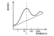
- the dotted line in FIG. 1 represents the change of the loss P with respect to the frequency f when the loss coefficient is constant with respect to the frequency f.
- a logarithmic scale is used for both the horizontal axis and the vertical axis.
- the real part ⁇ r ′ of the dielectric constant of water and the imaginary part ⁇ r ′′ of the dielectric constant of water correspond to the frequencies included in the frequency band composed of UHF, SHF, EHF, and THF.
- UHF is a frequency band from 300 MHz to 3 GHz.
- SHF is a frequency band from 3 GHz to 30 GHz.
- EHF is a frequency band from 30 GHz to 300 GHz.
- THF is a frequency band from 300 GHz to 3 THz. Therefore, the frequency band consisting of UHF, SHF, EHF, and THF is a frequency band from 300 MHz to 3 THz.
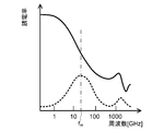
- the horizontal axis uses a logarithmic scale
- the vertical axis uses a linear scale.
- the solid line in FIG. 2 represents the real part ⁇ r ′ of the dielectric constant of water
- the dotted line in FIG. 2 represents the imaginary part ⁇ r ′′ of the dielectric constant of water.
- the inventors of the present application are dipolar with respect to the frequency in which the water loss coefficient is included in the frequency band consisting of UHF, SHF, EHF, and THF. The knowledge that it changes so that it may have a maximum value with a certain maximum frequency by a child polarization was acquired. Furthermore, the inventor of the present application has a ratio of the water loss coefficient to the maximum frequency of the water loss coefficient for the frequency of interest higher than the maximum frequency in the frequency band composed of UHF, SHF, EHF, and THF. The knowledge that the ratio of the maximum frequency to the frequency of interest is smaller.
- the loss P is smaller than the power loss with respect to the maximum frequency.
- the solid line in FIG. 1 represents a change in the signal power loss P with respect to the frequency f caused by the propagation of the signal in the water in the frequency band composed of UHF, SHF, EHF, and THF.
- the loss P changes so as to have a maximum value at the maximum value frequency f m in the frequency band composed of UHF, SHF, EHF, and THF.
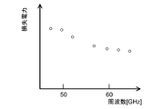
- FIG. 3 shows a signal power loss P caused by propagation of a signal in water to a frequency higher than the maximum frequency f m among the frequencies included in the frequency band composed of UHF, SHF, EHF, and THF. Represents the result measured experimentally.
- the horizontal axis uses a linear scale
- the vertical axis uses a logarithmic scale.
- the wireless device introduced into the living body is an imaginary part of the dielectric constant of water among the frequencies included in the frequency band consisting of UHF, SHF, EHF, and THF.
- a signal is wirelessly transmitted to the outside of the living body at a frequency where a loss coefficient, which is a ratio of the dielectric constant to the real part, is higher than a maximum frequency having a maximum value due to dipole polarization.
- the loss caused by the propagation of the power of the signal transmitted by the wireless device from the inside of the living body to the outside of the living body can be reduced as compared with the case where the signal is transmitted at the maximum frequency.
- the radio circuit including the antenna used for transmission can be made smaller than when the signal is transmitted at a frequency lower than the maximum frequency.
- the size of the wireless device can be made smaller than when signals are transmitted at a frequency lower than the maximum frequency. In this manner, according to the wireless device of each embodiment described later, the size of the wireless device can be reduced while reducing the loss of signal power.
- the detection system 1 of the first embodiment includes a wireless device 10, a power feeding device 20, and a detection device 30.
- the wireless device 10 is a wireless chip.
- the wireless device 10 may be a wireless tag, an IC (Integrated Circuit) tag, an RF (Radio Frequency) tag, or an RFID (Radio Frequency Identifier).
- the wireless device 10 is formed using a semiconductor.
- the wireless device 10 is introduced into the living body LB.
- the ingestion of the wireless device 10 by the living body LB is an example in which the wireless device 10 is introduced into the living body LB.
- the wireless device 10 may be ingested by the living body LB through the mouth of the living body LB.
- the wireless device 10 may be attached to medicine or food.
- wireless apparatus 10 may be mixed in a chemical
- the wireless device 10 may be directly introduced into a blood vessel or an organ via a needle or a tube. Further, the wireless device 10 may be introduced into the living body LB by being embedded in the living body LB.
- the wireless device 10 may be a device accommodated in a container such as a capsule.
- the wireless device 10 may be a capsule endoscope device.
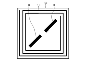
- the wireless device 10 has a flat plate shape and a square shape.
- the length of each side of the wireless device 10 is 1 mm.
- the wireless device 10 may have a shape (for example, a circular shape, an elliptical shape, or a polygonal shape) different from the square shape.
- the wireless device 10 includes a coil 11 and an antenna 12.
- the coil 11 is located at the outer edge of the wireless device 10.
- the coil 11 is wound along the outer edge of the wireless device 10 on a predetermined coil surface.
- the wireless device 10 receives the wireless signal from the outside of the living body LB and the wireless power from the outside of the living body LB in accordance with the electromagnetic induction method using the coil 11 in the state introduced into the living body LB. Receive power.
- the wireless device 10 receives and receives power from the power feeding device 20 located outside the living body LB.
- the frequency (in other words, the first frequency) used for wirelessly receiving signals from outside the living body LB and receiving power from the outside of the living body LB is wireless to the outside of the living body LB, which will be described later. Is lower than the frequency used for signal transmission (in other words, the second frequency).
- the frequency used for the reception and the power reception is 100 kHz or more and 50 MHz or less.
- the frequency used for the reception and the power reception is 13.56 MHz. Note that the frequency used for the reception may be different from the frequency used for the power reception.
- the wireless device 10 operates with the power received from the power supply device 20. Further, the wireless device 10 controls the operation of the wireless device 10 according to the signal received from the power supply device 20.
- the antenna 12 is located inside the coil 11.
- the antenna 12 is a set of dipole antennas extending along a diagonal line of the wireless device 10.
- the antenna 12 is an example of an omnidirectional antenna (in other words, an omni antenna).
- An omnidirectional antenna has a constant signal strength with respect to a direction in a specific plane.
- the antenna 12 may be two sets of dipole antennas extending along two diagonal lines of the wireless device 10.
- the antenna 12 may be an omnidirectional antenna different from the dipole antenna.
- the wireless device 10 transmits a signal wirelessly to the outside of the living body LB using the antenna 12 according to a radio wave system in a state where it is introduced into the living body LB.
- the wireless device 10 performs transmission to the detection device 30 located outside the living body LB.
- the wireless device 10 includes a memory (not shown), and transmits a signal representing information stored in advance in the memory to the outside of the living body LB.
- the information is information unique to the wireless device 10 or information for identifying the wireless device 10.
- the wireless device 10 may include a sensor and transmit a signal representing a physical quantity detected by the sensor.
- the physical quantity is temperature, pH, or the amount or concentration of a specific substance.
- the wireless device 10 may include a camera and transmit a signal representing a video or an image captured by the camera.
- the frequency used for wireless signal transmission to the outside of the living body LB is the dielectric constant of the imaginary part of the dielectric constant of water among the frequencies included in the frequency band consisting of UHF, SHF, EHF, and THF.
- the loss coefficient which is a ratio to the real part, is a frequency higher than the maximum frequency having a maximum value due to dipole polarization.
- the maximum value frequency is 22 GHz. Therefore, in this example, the frequency used for the transmission is higher than 22 GHz and lower than 3 THz. In this example, the frequency used for the transmission is 60 GHz.
- the power feeding device 20 includes a coil 21 and a control device 22.
- the coil 21 is wound around a predetermined coil surface.
- the coil surface is arranged so as to be orthogonal to the direction toward the front or back surface of the living body LB.
- the power feeding device 20 uses the coil 21 to perform wireless signal transmission to the inside of the living body LB and power transmission to the inside of the living body LB in accordance with the electromagnetic induction method. In this example, the power feeding device 20 performs transmission and power transmission to the wireless device 10 located inside the living body LB.
- the power feeding device 20 transmits a signal for controlling the wireless device 10 to the inside of the living body LB.
- a signal for controlling the wireless device 10 is a signal for starting the wireless device 10 (in other words, causing the wireless device 10 to start an operation), a signal for causing the wireless device 10 to transmit a signal, and causing the wireless device 10 to detect a physical quantity.
- the frequency used for wirelessly transmitting a signal to the inside of the living body LB and transmitting the wireless power to the inside of the living body LB is a wireless signal from the outside of the living body LB in the wireless device 10. And the frequency used for receiving electric power by radio from the outside of the living body LB.
- the control device 22 controls the current flowing through the coil 21.
- the detection device 30 includes an antenna 31 and a control device 32.
- the antenna 31 is a set of dipole antennas located on the antenna surface.
- the antenna surface is arranged so as to be orthogonal to the direction toward the surface of the living body LB.
- Detecting device 30 uses antenna 31 to receive a wireless signal from the inside of living body LB in accordance with a radio wave system. In this example, the detection device 30 performs reception from the wireless device 10 located inside the living body LB.
- the frequency used for wireless signal reception from the inside of the living body LB is the same as the frequency used in the wireless device 10 for wireless signal transmission to the outside of the living body LB.
- the control device 32 detects the position of the wireless device 10 based on the strength of the signal received using the antenna 31. In this example, when the intensity of the received signal is larger than a predetermined threshold, the control device 32 determines the position on the straight line extending from the antenna 31 in the direction orthogonal to the antenna surface as the position of the wireless device 10. Detect as.
- the threshold value is predetermined.
- the threshold value may be determined based on the strength of a signal received in a predetermined period. In this case, for example, the threshold value may be determined based on an average value of the strengths of signals received in a predetermined period.
- control device 22 and the control device 32 are realized by an integrated circuit (for example, LSI (Large Scale Integration)).
- LSI Large Scale Integration
- each of the control device 22 and the control device 32 may include a processing device and a storage device, and the processing device may implement the above functions by executing a program stored in the storage device.
- the wireless device 10 is introduced into the living body LB. Thereafter, at a predetermined timing, the power feeding device 20 transmits power to the wireless device 10 located inside the living body LB wirelessly and transmits a signal wirelessly to the wireless device 10 located inside the living body LB. Is performed using the coil 21 at the first frequency (13.56 MHz in this example).
- the wireless device 10 receives the wireless power from the power feeding device 20 located outside the living body LB using the coil 11 at the first frequency.
- the wireless device 10 receives a wireless signal from the power supply device 20 located outside the living body LB at the first frequency using the coil 11.
- the wireless device 10 operates with the received power and controls the operation of the wireless device 10 according to the received signal, thereby transmitting the signal wirelessly to the outside of the living body LB using the antenna 12. This is performed at the second frequency (60 GHz in this example).
- the detection device 30 is held by the user of the detection device 30.
- the user moves the detection device 30 so as to scan the surface of the living body LB while arranging the antenna surface of the detecting device 30 so as to be orthogonal to the direction toward the surface of the living body LB.
- the detection device 30 performs radio signal reception from the inside of the living body LB using the antenna 31 at the second frequency.
- the detection device 30 uses the antenna 31 to output a signal whose intensity is greater than the threshold value. Receive at frequency. Therefore, in this case, the detection device 30 detects a position on a straight line extending from the antenna 31 in a direction orthogonal to the antenna surface as the position of the wireless device 10.
- the wireless device 10 has the dielectric constant of the imaginary part of the dielectric constant of water among the frequencies included in the frequency band composed of UHF, SHF, EHF, and THF.
- a signal is wirelessly transmitted to the outside of the living body LB at a frequency whose loss coefficient, which is a ratio to the real part, is higher than a maximum frequency having a maximum value due to dipole polarization.
- the loss caused by the propagation of the power of the signal transmitted by the wireless device 10 from the inside of the living body LB to the outside of the living body LB can be reduced as compared with the case where the signal is transmitted at the maximum value frequency.
- the radio circuit including the antenna 12 used for transmission can be made smaller than when signal transmission is performed at a frequency lower than the maximum frequency.
- the size of the wireless device 10 can be reduced as compared with the case where signal transmission is performed at a frequency lower than the maximum frequency. In this manner, according to the wireless device 10, the size of the wireless device 10 can be reduced while reducing the loss of signal power.
- the antenna 12 used for wireless signal transmission to the outside of the living body LB is an omnidirectional antenna.
- the detection device 30 it is possible to increase the probability that the detection device 30 located outside the living body LB receives the signal transmitted by the wireless device 10. As a result, for example, the detection device 30 can detect the position of the wireless device 10 with high accuracy.
- the wireless device 10 receives the wireless signal from the outside of the living body LB at a frequency lower than the frequency used for wirelessly transmitting the signal to the outside of the living body LB, and the living body LB. Both power reception by radio from outside the LB is performed.
- the detection device 30 of the first embodiment is a ratio of the imaginary part of the dielectric constant of water to the real part of the dielectric constant of the frequencies included in the frequency band consisting of UHF, SHF, EHF, and THF.
- the position of the wireless device 10 is detected based on the intensity of the signal received at a frequency higher than the maximum frequency at which the loss coefficient is a maximum value due to the dipole polarization.
- the loss caused by the propagation of the power of the signal transmitted by the wireless device 10 from the inside of the living body LB to the outside of the living body LB can be reduced as compared with the case where the signal is received at the maximum frequency.
- the correlation between the intensity of the received signal and the position of the wireless device 10 can be increased as compared with the case where the signal is received at a frequency lower than the maximum frequency.
- the position of the wireless device 10 can be detected with higher accuracy than when the signal is received at a frequency lower than the maximum frequency.
- the position of the wireless device 10 can be detected with high accuracy.
- the detection system 1 may be configured not to perform one or both of power reception and reception from the outside of the living body LB by the wireless device 10.
- the detection system 1 may omit the power supply device 20.
- the wireless device 10 may omit the coil 11.
- the wireless device 10 may include a capacity for storing electric power. In this case, the wireless device 10 may operate with electric power stored in the capacity.
- the wireless device 10 may generate power. In this case, the wireless device 10 may operate with the generated power.
- the detection system 1 may be configured not to detect the position of the wireless device 10 by the detection device 30.
- the detection system of the second embodiment is different from the detection system of the first embodiment in that the detection device includes a power supply device.
- the difference between the detection system of the second embodiment and the first embodiment will be mainly described.
- the same reference numerals as those in the first embodiment are used.
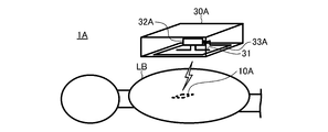
- the detection system 1 ⁇ / b> A of the second embodiment omits the power feeding device 20, and replaces the wireless device 10 and the detection device 30 of the first embodiment with the wireless device 10 ⁇ / b> A and the detection device 30 ⁇ / b> A. Is provided.
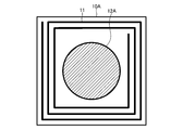
- the wireless device 10A is different from the wireless device 10 according to the first embodiment in that an antenna 12A is provided instead of the antenna 12.
- the antenna 12 ⁇ / b> A is located inside the coil 11.
- the antenna 12A is a patch antenna having a circular shape.
- the patch antenna may have a shape different from a circular shape (for example, an elliptical shape, a regular shape, or a polygonal shape).
- the antenna 12A is an example of a directional antenna.
- a directional antenna has a signal strength in a specific direction higher than the signal strength in another direction.
- the antenna 12A has a higher signal strength in a direction orthogonal to the coil surface of the wireless device 10A than in other directions.
- the antenna 12A may be a directional antenna different from the patch antenna.
- the detection device 30A is different from the detection device 30 of the first embodiment in that a control device 32A and a coil 33A are provided instead of the control device 32.
- the coil 33A is wound on a coil surface parallel to the antenna surface of the detection device 30A.
- the coil surface coincides with the antenna surface.
- the detection device 30A uses the coil 33A to perform wireless signal transmission into the living body LB and wireless power transmission into the living body LB in accordance with the electromagnetic induction method. In this example, the detection device 30A performs transmission and power transmission to the wireless device 10A located inside the living body LB.
- the frequency used for the wireless signal transmission to the inside of the living body LB and the power transmission to the inside of the living body LB is the signal used by the wireless device 10A for the wireless signal from the outside of the living body LB. And the frequency used for receiving electric power by radio from the outside of the living body LB.
- the control device 32A has a function of controlling the current flowing through the coil 33A in addition to the function of the control device 32 of the first embodiment.
- the same operation and effect as the detection system 1 of the first embodiment can be achieved.
- the antenna 12A is used for wireless signal transmission to the outside of the living body LB, and the signal strength in the direction orthogonal to the coil surface is the signal in the other direction. It is a directional antenna higher than strength.
- the detection device 30A when at least one of reception and power reception from the detection device 30A located outside the living body LB is performed, the probability that the detection device 30A receives a signal transmitted by the wireless device 10A is increased. Can do. As a result, for example, the detection device 30A can detect the position of the wireless device 10A with high accuracy.
- the detection device 30A of the second embodiment includes a coil 33A that is used both for wireless signal transmission to the inside of the living body LB and for wireless power transmission to the inside of the living body LB.
- the antenna 31 used for receiving a wireless signal from the inside of the living body LB is an omnidirectional antenna.
Landscapes
- Engineering & Computer Science (AREA)
- Computer Networks & Wireless Communication (AREA)
- Signal Processing (AREA)
- Variable-Direction Aerials And Aerial Arrays (AREA)
- Endoscopes (AREA)
- Near-Field Transmission Systems (AREA)
Abstract
無線装置(10)は、生体(LB)の内部に導入された装置である。無線装置(10)は、UHF(Ultra High Frequency)、SHF(Super High Frequency)、EHF(Extremely High Frequency)、及び、THF(Tremendously High Frequency)からなる周波数帯に含まれる周波数のうちの、水の誘電率の虚数部の、当該誘電率の実数部に対する比である損失係数が双極子分極によって極大値を有する極大値周波数よりも高い周波数にて、生体(LB)の外部へ無線による信号の送信を行なう。
Description
本発明は、無線装置、検出装置、検出システム、及び、無線通信方法に関する。
生体の内部に導入された無線装置によって無線により送信された信号を、生体の外部に位置する外部装置が受信する無線通信システムが知られている(例えば、非特許文献1及び非特許文献2を参照)。
ところで、生体は、水を相当に多く含む。従って、生体の内部から生体の外部への信号の伝搬は、水中の信号の伝搬によって十分に高い精度にて表される。また、無線装置により送信された信号の電力の、水中の伝搬によって生じる損失は、信号の周波数が高くなるほど大きくなる、と考えられている。
このため、無線通信システムは、無線装置による信号の送信に用いられる周波数として、1MHzから400MHzまでの周波数を用いる。
吉田、外2名、「人体における30MHz/400MHz帯デュアルモード通信の伝送路特性とBER評価」、信学技報、一般社団法人電子情報通信学会、平成26年12月、第114巻、第381号、p.19-24
石渡、外4名、「体内深部-体外間の容量結合型無線情報伝送~空気中及び液体模擬生体中における電圧利得特性の評価~」、信学技報、一般社団法人電子情報通信学会、平成26年5月、第114巻、第61号、p.9-12
ところで、400MHzの信号の波長は、約75cmである。また、ダイポールアンテナの長さは、波長の約4分の1である。このため、信号の送信にダイポールアンテナを用いる場合、無線装置の大きさは、相当に大きくなってしまう。
このように、上記無線装置においては、無線装置の大きさが過大になる虞があった。
このように、上記無線装置においては、無線装置の大きさが過大になる虞があった。
本発明の目的の一つは、信号の電力の損失を低減しながら、大きさを小さくすることが可能な無線装置を提供することにある。
一つの側面では、無線装置は、生体の内部に導入された装置である。
更に、この無線装置は、
UHF(Ultra High Frequency)、SHF(Super High Frequency)、EHF(Extremely High Frequency)、及び、THF(Tremendously High Frequency)からなる周波数帯に含まれる周波数のうちの、水の誘電率の虚数部の、当該誘電率の実数部に対する比である損失係数が双極子分極によって極大値を有する極大値周波数よりも高い周波数にて、上記生体の外部へ無線による信号の送信を行なう。
更に、この無線装置は、
UHF(Ultra High Frequency)、SHF(Super High Frequency)、EHF(Extremely High Frequency)、及び、THF(Tremendously High Frequency)からなる周波数帯に含まれる周波数のうちの、水の誘電率の虚数部の、当該誘電率の実数部に対する比である損失係数が双極子分極によって極大値を有する極大値周波数よりも高い周波数にて、上記生体の外部へ無線による信号の送信を行なう。
他の一つの側面では、検出装置は、生体の外部に位置する装置である。
更に、この検出装置は、
UHF、SHF、EHF、及び、THFからなる周波数帯に含まれる周波数のうちの、水の誘電率の虚数部の、当該誘電率の実数部に対する比である損失係数が双極子分極によって極大値を有する極大値周波数よりも高い周波数にて、上記生体の内部に導入された無線装置によって無線により送信された信号を受信し、上記受信した信号の強度に基づいて上記無線装置の位置を検出する。
更に、この検出装置は、
UHF、SHF、EHF、及び、THFからなる周波数帯に含まれる周波数のうちの、水の誘電率の虚数部の、当該誘電率の実数部に対する比である損失係数が双極子分極によって極大値を有する極大値周波数よりも高い周波数にて、上記生体の内部に導入された無線装置によって無線により送信された信号を受信し、上記受信した信号の強度に基づいて上記無線装置の位置を検出する。
他の一つの側面では、検出システムは、生体の内部に導入された無線装置と、上記生体の外部に位置する検出装置と、を備える。
更に、上記無線装置は、
UHF、SHF、EHF、及び、THFからなる周波数帯に含まれる周波数のうちの、水の誘電率の虚数部の、当該誘電率の実数部に対する比である損失係数が双極子分極によって極大値を有する極大値周波数よりも高い周波数にて、上記生体の外部へ無線による信号の送信を行ない、
上記検出装置は、
上記無線装置によって無線により送信された信号を受信し、上記受信した信号の強度に基づいて上記無線装置の位置を検出する。
更に、上記無線装置は、
UHF、SHF、EHF、及び、THFからなる周波数帯に含まれる周波数のうちの、水の誘電率の虚数部の、当該誘電率の実数部に対する比である損失係数が双極子分極によって極大値を有する極大値周波数よりも高い周波数にて、上記生体の外部へ無線による信号の送信を行ない、
上記検出装置は、
上記無線装置によって無線により送信された信号を受信し、上記受信した信号の強度に基づいて上記無線装置の位置を検出する。
他の一つの側面では、無線通信方法は、
無線装置を生体の内部に導入し、
上記無線装置が、UHF、SHF、EHF、及び、THFからなる周波数帯に含まれる周波数のうちの、水の誘電率の虚数部の、当該誘電率の実数部に対する比である損失係数が双極子分極によって極大値を有する極大値周波数よりも高い周波数にて、上記生体の外部へ無線による信号の送信を行なう。
無線装置を生体の内部に導入し、
上記無線装置が、UHF、SHF、EHF、及び、THFからなる周波数帯に含まれる周波数のうちの、水の誘電率の虚数部の、当該誘電率の実数部に対する比である損失係数が双極子分極によって極大値を有する極大値周波数よりも高い周波数にて、上記生体の外部へ無線による信号の送信を行なう。
信号の電力の損失を低減しながら、無線装置の大きさを小さくすることができる。
誘電体における信号の伝搬によって生じる、信号の電力の損失Pは、数式1により表される。誘電体における信号の伝搬によって生じる、信号の電力の損失Pは、損失電力とも表される。αは、信号の周波数に対して一定である係数を表す。fは、信号の周波数を表す。εr’は、誘電体の誘電率の実数部を表す。εr’’は、誘電体の誘電率の虚数部を表す。誘電率の虚数部εr’’を誘電率の実数部εr’により除した値εr’’/εr’は、損失係数、又は、誘電正接とも表される。

例えば、周波数fに対して損失係数が一定である場合、損失Pは、数式1により表されるように、周波数fに比例して増加する。図1の点線は、周波数fに対して損失係数が一定である場合における、損失Pの周波数fに対する変化を表す。図1において、横軸及び縦軸の両方は、対数目盛を用いている。
ところで、一例として、水の誘電率の実数部εr’、及び、水の誘電率の虚数部εr’’は、UHF、SHF、EHF、及び、THFからなる周波数帯に含まれる周波数に対して、図2により表されるように変化する。UHFは、300MHzから3GHzまでの周波数帯である。SHFは、3GHzから30GHzまでの周波数帯である。EHFは、30GHzから300GHzまでの周波数帯である。THFは、300GHzから3THzまでの周波数帯である。従って、UHF、SHF、EHF、及び、THFからなる周波数帯は、300MHzから3THzまでの周波数帯である。
図2において、横軸は、対数目盛を用い、縦軸は、線形目盛を用いている。図2の実線は、水の誘電率の実数部εr’を表し、図2の点線は、水の誘電率の虚数部εr’’を表す。水の誘電率の虚数部εr’’は、22GHzの近傍の周波数fmにおいて双極子分極によって極大値を有するとともに、2THzの近傍において原子分極によって極大値を有する。
図2により表される水の誘電率の変化に基づいて、本願の発明者は、水の損失係数が、UHF、SHF、EHF、及び、THFからなる周波数帯に含まれる周波数に対して、双極子分極によって、ある極大値周波数にて極大値を有するように変化する、という知見を得た。更に、本願の発明者は、UHF、SHF、EHF、及び、THFからなる周波数帯においては、極大値周波数よりも高い着目周波数に対する水の損失係数の、極大値周波数に対する水の損失係数の比が、極大値周波数の当該着目周波数に対する比よりも小さい、という知見を得た。
上記知見によれば、UHF、SHF、EHF、及び、THFからなる周波数帯に含まれる周波数のうちの、極大値周波数よりも高い周波数に対して、水中の信号の伝搬によって生じる、信号の電力の損失Pは、極大値周波数に対する電力の損失よりも小さい。
図1の実線は、UHF、SHF、EHF、及び、THFからなる周波数帯における、水中の信号の伝搬によって生じる、信号の電力の損失Pの、周波数fに対する変化を表す。損失Pは、UHF、SHF、EHF、及び、THFからなる周波数帯において、極大値周波数fmにて極大値を有するように変化する。
図3は、UHF、SHF、EHF、及び、THFからなる周波数帯に含まれる周波数のうちの、極大値周波数fmよりも高い周波数に対する、水中の信号の伝搬によって生じる、信号の電力の損失Pを実験により測定された結果を表す。図3において、横軸は、線形目盛を用い、縦軸は、対数目盛を用いている。
図3は、UHF、SHF、EHF、及び、THFからなる周波数帯に含まれる周波数のうちの、極大値周波数fmよりも高い周波数に対する、水中の信号の伝搬によって生じる、信号の電力の損失Pを実験により測定された結果を表す。図3において、横軸は、線形目盛を用い、縦軸は、対数目盛を用いている。
そこで、後述する各実施形態において、生体の内部に導入された無線装置は、UHF、SHF、EHF、及び、THFからなる周波数帯に含まれる周波数のうちの、水の誘電率の虚数部の、当該誘電率の実数部に対する比である損失係数が双極子分極によって極大値を有する極大値周波数よりも高い周波数にて、生体の外部へ無線による信号の送信を行なう。
これによれば、極大値周波数にて信号の送信が行なわれる場合よりも、無線装置により送信された信号の電力の、生体の内部から生体の外部への伝搬によって生じる損失を低減できる。更に、極大値周波数よりも低い周波数にて信号の送信が行なわれる場合よりも、送信に用いられるアンテナを含む無線回路を小さくすることができる。この結果、極大値周波数よりも低い周波数にて信号の送信が行なわれる場合よりも、無線装置の大きさを小さくすることができる。
このようにして、後述する各実施形態の無線装置によれば、信号の電力の損失を低減しながら、無線装置の大きさを小さくすることができる。
このようにして、後述する各実施形態の無線装置によれば、信号の電力の損失を低減しながら、無線装置の大きさを小さくすることができる。
以下、本発明の、無線装置、検出装置、検出システム、及び、無線通信方法、に関する各実施形態について図4乃至図7を参照しながら説明する。
<第1実施形態>
(構成)
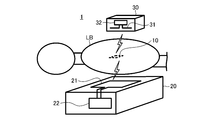
図4に表されるように、第1実施形態の検出システム1は、無線装置10と、給電装置20と、検出装置30と、を備える。
(構成)
図4に表されるように、第1実施形態の検出システム1は、無線装置10と、給電装置20と、検出装置30と、を備える。
本例では、無線装置10は、無線チップである。無線装置10は、無線タグ、IC(Integrated Circuit)タグ、RF(Radio Frequency)タグ、又は、RFID(Radio Frequency Identifier)であってもよい。例えば、無線装置10は、半導体を用いて形成される。
無線装置10は、生体LBの内部に導入される。無線装置10が生体LBによって摂取されることは、無線装置10が生体LBの内部に導入されることの一例である。例えば、無線装置10は、生体LBの口を通って生体LBによって摂取されてよい。無線装置10は、薬品又は食品に取り付けられてよい。また、無線装置10は、薬品又は食品に混入されてよい。
また、無線装置10は、血管の内部、又は、器官の内部に、針又は管等を介して直接に導入されてもよい。また、無線装置10は、生体LBの内部に埋設されることにより生体LBの内部に導入されてもよい。
また、無線装置10は、カプセル等の容器に収容された装置であってもよい。例えば、無線装置10は、カプセル内視鏡装置であってもよい。
また、無線装置10は、カプセル等の容器に収容された装置であってもよい。例えば、無線装置10は、カプセル内視鏡装置であってもよい。
無線装置10は、図5に表されるように、平板状であり且つ正方形状を有する。例えば、無線装置10の各辺の長さは、1mmである。なお、無線装置10は、正方形状と異なる形状(例えば、円形状、楕円形状、又は、多角形状等)を有してもよい。
無線装置10は、コイル11と、アンテナ12と、を備える。
コイル11は、無線装置10の外縁部に位置する。コイル11は、所定のコイル面にて、無線装置10の外縁に沿って巻回される。
コイル11は、無線装置10の外縁部に位置する。コイル11は、所定のコイル面にて、無線装置10の外縁に沿って巻回される。
無線装置10は、生体LBの内部に導入された状態において、コイル11を用いて、電磁誘導方式に従って、生体LBの外部からの無線による信号の受信、及び、生体LBの外部からの無線による電力の受電を行なう。本例では、無線装置10は、生体LBの外部に位置する給電装置20からの受信及び受電を行なう。
生体LBの外部からの無線による信号の受信、及び、生体LBの外部からの無線による電力の受電に用いられる周波数(換言すると、第1の周波数)は、後述する、生体LBの外部への無線による信号の送信に用いられる周波数(換言すると、第2の周波数)よりも低い。本例では、上記受信及び上記受電に用いられる周波数は、100kHz以上であり且つ50MHz以下である。本例では、上記受信及び上記受電に用いられる周波数は、13.56MHzである。なお、上記受信に用いられる周波数は、上記受電に用いられる周波数と異なっていてもよい。
無線装置10は、給電装置20から受電された電力によって動作する。更に、無線装置10は、給電装置20から受信された信号に従って無線装置10の動作を制御する。
アンテナ12は、コイル11の内側に位置する。本例では、アンテナ12は、無線装置10の対角線に沿って延びる1組のダイポールアンテナである。アンテナ12は、全方向性アンテナ(換言すると、オムニアンテナ)の一例である。全方向性アンテナは、特定の平面において、信号の強度が方向に対して一定である。なお、アンテナ12は、無線装置10の2つの対角線にそれぞれ沿って延びる2組のダイポールアンテナであってもよい。また、アンテナ12は、ダイポールアンテナと異なる全方向性アンテナであってもよい。
無線装置10は、生体LBの内部に導入された状態において、アンテナ12を用いて、電波方式に従って、生体LBの外部への無線による信号の送信を行なう。本例では、無線装置10は、生体LBの外部に位置する検出装置30への送信を行なう。
本例では、無線装置10は、図示しないメモリを備え、メモリに予め記憶されている情報を表す信号を生体LBの外部へ送信する。例えば、情報は、無線装置10に固有の情報、又は、無線装置10を識別する情報である。
なお、無線装置10は、センサを備え、センサにより検出された物理量を表す信号を送信してもよい。例えば、物理量は、温度、pH、又は、特定の物質の量若しくは濃度等である。また、無線装置10は、カメラを備え、カメラにより撮影された映像又は画像を表す信号を送信してもよい。
生体LBの外部への無線による信号の送信に用いられる周波数は、UHF、SHF、EHF、及び、THFからなる周波数帯に含まれる周波数のうちの、水の誘電率の虚数部の、当該誘電率の実数部に対する比である損失係数が双極子分極によって極大値を有する極大値周波数よりも高い周波数である。本例では、極大値周波数は、22GHzである。従って、本例では、上記送信に用いられる周波数は、22GHzよりも高く且つ3THz以下である。本例では、上記送信に用いられる周波数は、60GHzである。
図4に表されるように、給電装置20は、コイル21と、制御装置22と、を備える。
コイル21は、所定のコイル面にて巻回される。例えば、コイル面は、生体LBの正面又は背面に向かう方向に直交するように配置される。
コイル21は、所定のコイル面にて巻回される。例えば、コイル面は、生体LBの正面又は背面に向かう方向に直交するように配置される。
給電装置20は、コイル21を用いて、電磁誘導方式に従って、生体LBの内部への無線による信号の送信、及び、生体LBの内部への無線による電力の送電を行なう。本例では、給電装置20は、生体LBの内部に位置する無線装置10への送信及び送電を行なう。
本例では、給電装置20は、無線装置10を制御する信号を生体LBの内部へ送信する。例えば、無線装置10を制御する信号は、無線装置10を起動する(換言すると、無線装置10に動作を開始させる)信号、無線装置10に信号を送信させる信号、無線装置10に物理量を検出させる信号、又は、無線装置10に映像若しくは画像を撮影させる信号等である。
給電装置20において、生体LBの内部への無線による信号の送信、及び、生体LBの内部への無線による電力の送電に用いられる周波数は、無線装置10において、生体LBの外部からの無線による信号の受信、及び、生体LBの外部からの無線による電力の受電に用いられる周波数とそれぞれ同じである。
制御装置22は、コイル21に流れる電流を制御する。
制御装置22は、コイル21に流れる電流を制御する。
検出装置30は、アンテナ31と、制御装置32と、を備える。
アンテナ31は、アンテナ面に位置する1組のダイポールアンテナである。例えば、アンテナ面は、生体LBの表面に向かう方向に直交するように配置される。
アンテナ31は、アンテナ面に位置する1組のダイポールアンテナである。例えば、アンテナ面は、生体LBの表面に向かう方向に直交するように配置される。
検出装置30は、アンテナ31を用いて、電波方式に従って、生体LBの内部からの無線による信号の受信を行なう。本例では、検出装置30は、生体LBの内部に位置する無線装置10からの受信を行なう。
検出装置30において、生体LBの内部からの無線による信号の受信に用いられる周波数は、無線装置10において、生体LBの外部への無線による信号の送信に用いられる周波数と同じである。
制御装置32は、アンテナ31を用いて受信された信号の強度に基づいて無線装置10の位置を検出する。本例では、制御装置32は、受信された信号の強度が、所定の閾値よりも大きい場合に、アンテナ31から、アンテナ面に直交する方向に延びた直線上の位置を、無線装置10の位置として検出する。
本例では、上記閾値は、予め定められる。なお、上記閾値は、所定の期間において受信された信号の強度に基づいて定められてもよい。この場合、例えば、上記閾値は、所定の期間において受信された信号の強度の平均値に基づいて定められてよい。
本例では、制御装置22及び制御装置32は、集積回路(例えば、LSI(Large Scale Integration)等)により実現される。なお、制御装置22及び制御装置32のそれぞれは、処理装置と記憶装置とを備え、処理装置が記憶装置に記憶されたプログラムを実行することにより、上記機能を実現してもよい。
(動作)
次に、検出システム1の動作について説明する。
先ず、無線装置10は、生体LBの内部に導入される。その後、所定のタイミングにて、給電装置20は、生体LBの内部に位置する無線装置10への無線による電力の送電、及び、生体LBの内部に位置する無線装置10への無線による信号の送信を、コイル21を用いて第1の周波数(本例では、13.56MHz)にて行なう。
次に、検出システム1の動作について説明する。
先ず、無線装置10は、生体LBの内部に導入される。その後、所定のタイミングにて、給電装置20は、生体LBの内部に位置する無線装置10への無線による電力の送電、及び、生体LBの内部に位置する無線装置10への無線による信号の送信を、コイル21を用いて第1の周波数(本例では、13.56MHz)にて行なう。
これにより、無線装置10は、生体LBの外部に位置する給電装置20からの無線による電力の受電を、コイル11を用いて第1の周波数にて行なう。無線装置10は、受電された電力により動作することにより、生体LBの外部に位置する給電装置20からの無線による信号の受信を、コイル11を用いて第1の周波数にて行なう。
そして、無線装置10は、受電された電力により動作するとともに、受信された信号に従って無線装置10の動作を制御することにより、生体LBの外部への無線による信号の送信を、アンテナ12を用いて第2の周波数(本例では、60GHz)にて行なう。
本例では、検出装置30は、検出装置30のユーザによって保持される。ユーザは、検出装置30のアンテナ面を、生体LBの表面に向かう方向に直交するように配置しながら、生体LBの表面を走査するように、検出装置30を移動させる。
検出装置30は、生体LBの内部からの無線による信号の受信を、アンテナ31を用いて第2の周波数にて行なう。
アンテナ31から、アンテナ面に直交する方向に延びた直線の近傍に、無線装置10が位置している場合、検出装置30は、強度が閾値よりも大きい信号を、アンテナ31を用いて第2の周波数にて受信する。従って、この場合、検出装置30は、アンテナ31から、アンテナ面に直交する方向に延びた直線上の位置を、無線装置10の位置として検出する。
アンテナ31から、アンテナ面に直交する方向に延びた直線の近傍に、無線装置10が位置している場合、検出装置30は、強度が閾値よりも大きい信号を、アンテナ31を用いて第2の周波数にて受信する。従って、この場合、検出装置30は、アンテナ31から、アンテナ面に直交する方向に延びた直線上の位置を、無線装置10の位置として検出する。
以上、説明したように、第1実施形態の無線装置10は、UHF、SHF、EHF、及び、THFからなる周波数帯に含まれる周波数のうちの、水の誘電率の虚数部の、当該誘電率の実数部に対する比である損失係数が双極子分極によって極大値を有する極大値周波数よりも高い周波数にて、生体LBの外部へ無線による信号の送信を行なう。
これによれば、極大値周波数にて信号の送信が行なわれる場合よりも、無線装置10により送信された信号の電力の、生体LBの内部から生体LBの外部への伝搬によって生じる損失を低減できる。更に、極大値周波数よりも低い周波数にて信号の送信が行なわれる場合よりも、送信に用いられるアンテナ12を含む無線回路を小さくすることができる。この結果、極大値周波数よりも低い周波数にて信号の送信が行なわれる場合よりも、無線装置10の大きさを小さくすることができる。
このようにして、無線装置10によれば、信号の電力の損失を低減しながら、無線装置10の大きさを小さくすることができる。
このようにして、無線装置10によれば、信号の電力の損失を低減しながら、無線装置10の大きさを小さくすることができる。
更に、第1実施形態の無線装置10において、生体LBの外部への無線による信号の送信に用いられるアンテナ12は、全方向性アンテナである。
これによれば、生体LBの外部に位置する検出装置30が、無線装置10により送信された信号を受信する確率を高めることができる。この結果、例えば、検出装置30は、無線装置10の位置を高い精度にて検出できる。
加えて、第1実施形態の無線装置10は、生体LBの外部への無線による信号の送信に用いられる周波数よりも低い周波数にて、生体LBの外部からの無線による信号の受信、及び、生体LBの外部からの無線による電力の受電の両方を行なう。
これによれば、生体LBの外部から信号を受信する確率、及び、生体LBの外部からの電力を受電する確率、の両方を高めることができる。
更に、第1実施形態の検出装置30は、UHF、SHF、EHF、及び、THFからなる周波数帯に含まれる周波数のうちの、水の誘電率の虚数部の、当該誘電率の実数部に対する比である損失係数が双極子分極によって極大値を有する極大値周波数よりも高い周波数にて受信した信号の強度に基づいて無線装置10の位置を検出する。
これによれば、極大値周波数にて信号の受信が行なわれる場合よりも、無線装置10により送信された信号の電力の、生体LBの内部から生体LBの外部への伝搬によって生じる損失を低減できる。更に、極大値周波数よりも低い周波数にて信号の受信が行なわれる場合よりも、受信された信号の強度と無線装置10の位置との相関を高めることができる。この結果、極大値周波数よりも低い周波数にて信号の受信が行なわれる場合よりも、無線装置10の位置を高い精度にて検出できる。
このようにして、検出装置30によれば、無線装置10の位置を高い精度にて検出できる。
このようにして、検出装置30によれば、無線装置10の位置を高い精度にて検出できる。
なお、検出システム1は、無線装置10による、生体LBの外部からの受電及び受信の一方又は両方を行なわないように構成されていてもよい。
無線装置10による、生体LBの外部からの受電及び受信の両方が行なわれない場合、検出システム1は、給電装置20を省略してよい。更に、この場合、無線装置10は、コイル11を省略してよい。
また、無線装置10による、生体LBの外部からの受電が行なわれない場合、無線装置10は、電力を蓄電する容量を備えていてもよい。この場合、無線装置10は、容量に蓄電された電力によって動作してよい。
また、無線装置10による、生体LBの外部からの受電が行なわれない場合、無線装置10は、電力を生成してもよい。この場合、無線装置10は、生成した電力によって動作してよい。
無線装置10による、生体LBの外部からの受電及び受信の両方が行なわれない場合、検出システム1は、給電装置20を省略してよい。更に、この場合、無線装置10は、コイル11を省略してよい。
また、無線装置10による、生体LBの外部からの受電が行なわれない場合、無線装置10は、電力を蓄電する容量を備えていてもよい。この場合、無線装置10は、容量に蓄電された電力によって動作してよい。
また、無線装置10による、生体LBの外部からの受電が行なわれない場合、無線装置10は、電力を生成してもよい。この場合、無線装置10は、生成した電力によって動作してよい。
また、検出システム1は、検出装置30による、無線装置10の位置の検出を行なわないように構成されていてもよい。
<第2実施形態>
次に、第2実施形態の検出システムについて説明する。第2実施形態の検出システムは、第1実施形態の検出システムに対して、検出装置が給電装置を含む点において相違している。以下、第2実施形態の検出システムの、第1実施形態に対する相違点を中心として説明する。なお、第2実施形態の説明において、第1実施形態と共通する又は対応する符号が用いられる。
次に、第2実施形態の検出システムについて説明する。第2実施形態の検出システムは、第1実施形態の検出システムに対して、検出装置が給電装置を含む点において相違している。以下、第2実施形態の検出システムの、第1実施形態に対する相違点を中心として説明する。なお、第2実施形態の説明において、第1実施形態と共通する又は対応する符号が用いられる。
図6に表されるように、第2実施形態の検出システム1Aは、給電装置20を省略するとともに、第1実施形態の無線装置10及び検出装置30に代えて、無線装置10A及び検出装置30Aを備える。
図7に表されるように、無線装置10Aは、第1実施形態の無線装置10に対して、アンテナ12に代えて、アンテナ12Aを備える点で相違する。
アンテナ12Aは、コイル11の内側に位置する。本例では、アンテナ12Aは、円形状を有するパッチアンテナである。なお、パッチアンテナは、円形状と異なる形状(例えば、楕円形状、正角形状、又は、多角形状等)を有してもよい。
アンテナ12Aは、コイル11の内側に位置する。本例では、アンテナ12Aは、円形状を有するパッチアンテナである。なお、パッチアンテナは、円形状と異なる形状(例えば、楕円形状、正角形状、又は、多角形状等)を有してもよい。
アンテナ12Aは、指向性アンテナの一例である。指向性アンテナは、特定の方向における信号の強度が他の方向における信号の強度よりも高い。本例では、アンテナ12Aは、無線装置10Aのコイル面に直交する方向における信号の強度が他の方向における信号の強度よりも高い。なお、アンテナ12Aは、パッチアンテナと異なる指向性アンテナであってもよい。
図6に表されるように、検出装置30Aは、第1実施形態の検出装置30に対して、制御装置32に代えて、制御装置32A及びコイル33Aを備える点で相違する。
コイル33Aは、検出装置30Aのアンテナ面と平行なコイル面にて巻回される。本例では、コイル面は、アンテナ面と一致する。
検出装置30Aは、コイル33Aを用いて、電磁誘導方式に従って、生体LBの内部への無線による信号の送信、及び、生体LBの内部への無線による電力の送電を行なう。本例では、検出装置30Aは、生体LBの内部に位置する無線装置10Aへの送信及び送電を行なう。
検出装置30Aは、コイル33Aを用いて、電磁誘導方式に従って、生体LBの内部への無線による信号の送信、及び、生体LBの内部への無線による電力の送電を行なう。本例では、検出装置30Aは、生体LBの内部に位置する無線装置10Aへの送信及び送電を行なう。
検出装置30Aにおいて、生体LBの内部への無線による信号の送信、及び、生体LBの内部への無線による電力の送電に用いられる周波数は、無線装置10Aにおいて、生体LBの外部からの無線による信号の受信、及び、生体LBの外部からの無線による電力の受電に用いられる周波数とそれぞれ同じである。
制御装置32Aは、第1実施形態の制御装置32の機能に加えて、コイル33Aに流れる電流を制御する機能を有する。
制御装置32Aは、第1実施形態の制御装置32の機能に加えて、コイル33Aに流れる電流を制御する機能を有する。
第2実施形態の検出システム1Aによれば、第1実施形態の検出システム1と同様の作用及び効果を奏することができる。
更に、第2実施形態の無線装置10Aにおいて、アンテナ12Aは、生体LBの外部への無線による信号の送信に用いられ、且つ、コイル面に直交する方向における信号の強度が他の方向における信号の強度よりも高い指向性アンテナである。
これによれば、生体LBの外部に位置する検出装置30Aからの受信及び受電の少なくとも一方が行なわれた場合に、検出装置30Aが、無線装置10Aにより送信された信号を受信する確率を高めることができる。この結果、例えば、検出装置30Aは、無線装置10Aの位置を高い精度にて検出できる。
加えて、第2実施形態の検出装置30Aは、生体LBの内部への無線による信号の送信、及び、生体LBの内部への無線による電力の送電の両方に用いられるコイル33Aを備える。更に、検出装置30Aにおいて、生体LBの内部からの無線による信号の受信に用いられるアンテナ31は、全方向性アンテナである。
これによれば、生体LBの内部に導入された無線装置10Aへの送信及び送電の少なくとも一方が行なわれた場合に、無線装置10Aにより送信された信号を受信する確率を高めることができる。
なお、本発明は、上述した実施形態に限定されない。例えば、上述した実施形態に、本発明の趣旨を逸脱しない範囲内において当業者が理解し得る様々な変更が加えられてよい。例えば、本発明の趣旨を逸脱しない範囲内において、上述した実施形態の他の変形例として、上述した実施形態及び変形例の任意の組み合わせが採用されてもよい。
1,1A 検出システム
10,10A 無線装置
11 コイル
12,12A アンテナ
20 給電装置
21 コイル
22 制御装置
30,30A 検出装置
31 アンテナ
32,32A 制御装置
33A コイル
LB 生体
10,10A 無線装置
11 コイル
12,12A アンテナ
20 給電装置
21 コイル
22 制御装置
30,30A 検出装置
31 アンテナ
32,32A 制御装置
33A コイル
LB 生体
Claims (11)
- 生体の内部に導入された無線装置であって、
UHF(Ultra High Frequency)、SHF(Super High Frequency)、EHF(Extremely High Frequency)、及び、THF(Tremendously High Frequency)からなる周波数帯に含まれる周波数のうちの、水の誘電率の虚数部の、当該誘電率の実数部に対する比である損失係数が双極子分極によって極大値を有する極大値周波数よりも高い周波数にて、前記生体の外部へ無線による信号の送信を行なう、無線装置。 - 請求項1に記載の無線装置であって、
前記極大値周波数は、22GHzである、無線装置。 - 請求項1又は請求項2に記載の無線装置であって、
前記送信に用いられる全方向性アンテナを備える、無線装置。 - 請求項1又は請求項2に記載の無線装置であって、
コイル面に形成され、且つ、前記生体の外部からの無線による信号の受信、及び、前記生体の外部からの無線による電力の受電の少なくとも一方に用いられるコイルと、
前記送信に用いられ、且つ、前記コイル面に直交する方向における信号の強度が他の方向における信号の強度よりも高い指向性アンテナと、
を備える、無線装置。 - 請求項1乃至請求項4のいずれか一項に記載の無線装置であって、
前記送信に用いられる周波数よりも低い周波数にて、前記生体の外部からの無線による信号の受信、及び、前記生体の外部からの無線による電力の受電の少なくとも一方を行なう、無線装置。 - 請求項5に記載の無線装置であって、
前記受信及び前記受電の少なくとも一方に用いられる周波数は、100kHz以上であり且つ50MHz以下である、無線装置。 - 生体の外部に位置する検出装置であって、
UHF(Ultra High Frequency)、SHF(Super High Frequency)、EHF(Extremely High Frequency)、及び、THF(Tremendously High Frequency)からなる周波数帯に含まれる周波数のうちの、水の誘電率の虚数部の、当該誘電率の実数部に対する比である損失係数が双極子分極によって極大値を有する極大値周波数よりも高い周波数にて、前記生体の内部に導入された無線装置によって無線により送信された信号を受信し、前記受信した信号の強度に基づいて前記無線装置の位置を検出する、検出装置。 - 請求項7に記載の検出装置であって、
前記生体の内部への無線による信号の送信、及び、前記生体の内部への無線による電力の送電の少なくとも一方に用いられるコイルと、
前記受信に用いられる全方向性アンテナと、
を備える、検出装置。 - 生体の内部に導入された無線装置と、
前記生体の外部に位置する検出装置と、
を備える検出システムであって、
前記無線装置は、
UHF(Ultra High Frequency)、SHF(Super High Frequency)、EHF(Extremely High Frequency)、及び、THF(Tremendously High Frequency)からなる周波数帯に含まれる周波数のうちの、水の誘電率の虚数部の、当該誘電率の実数部に対する比である損失係数が双極子分極によって極大値を有する極大値周波数よりも高い周波数にて、前記生体の外部へ無線による信号の送信を行ない、
前記検出装置は、
前記無線装置によって無線により送信された信号を受信し、前記受信した信号の強度に基づいて前記無線装置の位置を検出する、検出システム。 - 無線装置を生体の内部に導入し、
前記無線装置が、UHF(Ultra High Frequency)、SHF(Super High Frequency)、EHF(Extremely High Frequency)、及び、THF(Tremendously High Frequency)からなる周波数帯に含まれる周波数のうちの、水の誘電率の虚数部の、当該誘電率の実数部に対する比である損失係数が双極子分極によって極大値を有する極大値周波数よりも高い周波数にて、前記生体の外部へ無線による信号の送信を行なう、無線通信方法。 - 請求項10に記載の無線通信方法であって、
前記生体の外部に位置する検出装置が、前記無線装置によって無線により送信された信号を受信し、
前記検出装置が、前記受信した信号の強度に基づいて前記無線装置の位置を検出する、無線通信方法。
Applications Claiming Priority (2)
| Application Number | Priority Date | Filing Date | Title |
|---|---|---|---|
| JP2015-070693 | 2015-03-31 | ||
| JP2015070693A JP6590398B2 (ja) | 2015-03-31 | 2015-03-31 | 無線装置、検出装置、検出システム、及び、無線通信方法 |
Publications (1)
| Publication Number | Publication Date |
|---|---|
| WO2016158244A1 true WO2016158244A1 (ja) | 2016-10-06 |
Family
ID=57005692
Family Applications (1)
| Application Number | Title | Priority Date | Filing Date |
|---|---|---|---|
| PCT/JP2016/057168 Ceased WO2016158244A1 (ja) | 2015-03-31 | 2016-03-08 | 無線装置、検出装置、検出システム、及び、無線通信方法 |
Country Status (2)
| Country | Link |
|---|---|
| JP (1) | JP6590398B2 (ja) |
| WO (1) | WO2016158244A1 (ja) |
Citations (4)
| Publication number | Priority date | Publication date | Assignee | Title |
|---|---|---|---|---|
| JP2006130163A (ja) * | 2004-11-08 | 2006-05-25 | Olympus Medical Systems Corp | 超音波診断医用カプセル |
| JP2010004443A (ja) * | 2008-06-23 | 2010-01-07 | Toshiba Corp | 通信システム及び通信方法 |
| JP2011130840A (ja) * | 2009-12-22 | 2011-07-07 | Olympus Corp | 生体情報取得システム |
| WO2015029741A1 (ja) * | 2013-08-28 | 2015-03-05 | オリンパスメディカルシステムズ株式会社 | カプセル型内視鏡システム |
Family Cites Families (2)
| Publication number | Priority date | Publication date | Assignee | Title |
|---|---|---|---|---|
| JP4436631B2 (ja) * | 2003-08-04 | 2010-03-24 | オリンパス株式会社 | カプセル内視鏡 |
| JP5534202B2 (ja) * | 2010-07-07 | 2014-06-25 | ソニー株式会社 | 送受信システム |
-
2015
- 2015-03-31 JP JP2015070693A patent/JP6590398B2/ja not_active Expired - Fee Related
-
2016
- 2016-03-08 WO PCT/JP2016/057168 patent/WO2016158244A1/ja not_active Ceased
Patent Citations (4)
| Publication number | Priority date | Publication date | Assignee | Title |
|---|---|---|---|---|
| JP2006130163A (ja) * | 2004-11-08 | 2006-05-25 | Olympus Medical Systems Corp | 超音波診断医用カプセル |
| JP2010004443A (ja) * | 2008-06-23 | 2010-01-07 | Toshiba Corp | 通信システム及び通信方法 |
| JP2011130840A (ja) * | 2009-12-22 | 2011-07-07 | Olympus Corp | 生体情報取得システム |
| WO2015029741A1 (ja) * | 2013-08-28 | 2015-03-05 | オリンパスメディカルシステムズ株式会社 | カプセル型内視鏡システム |
Also Published As
| Publication number | Publication date |
|---|---|
| JP6590398B2 (ja) | 2019-10-16 |
| JP2016192631A (ja) | 2016-11-10 |
Similar Documents
| Publication | Publication Date | Title |
|---|---|---|
| Yousaf et al. | Compacted conformal implantable antenna with multitasking capabilities for ingestible capsule endoscope | |
| Islam et al. | Microwave breast phantom measurement system with compact side slotted directional antenna | |
| KR102471197B1 (ko) | 안테나 장치 및 이를 포함하는 전자 장치 | |
| Kaufmann et al. | Wearable Quarter‐Wave Folded Microstrip Antenna for Passive UHF RFID Applications | |
| US20220312402A1 (en) | Method and device for performing beam searching in mobile communication system | |
| US10206603B2 (en) | Microwave transmission device and microwave transmission system | |
| Kim et al. | An ultra-wideband conformal meandered loop antenna for wireless capsule endoscopy | |
| US20210059526A1 (en) | Medical implant with wireless communication | |
| EP3238140A1 (en) | Method and apparatus for energy harvest from a proximity coupling device | |
| EP3243342B1 (en) | Beamforming to a harvesting device | |
| Govindan et al. | Design and analysis of a conformal MIMO ingestible bolus sensor antenna for wireless capsule endoscopy for animal husbandry | |
| JP5910883B2 (ja) | 無線タグ用複合アンテナ | |
| Kiani et al. | A compact multichannel implantable antenna for high-speed telemetry | |
| Pawar et al. | A comprehensive review of different antennas for IoT applications | |
| US10078127B2 (en) | Tracking spatial placement of HF RFID tag objects on a surface using multiple reception antennas | |
| JP6590398B2 (ja) | 無線装置、検出装置、検出システム、及び、無線通信方法 | |
| Waris et al. | Wearable passive UHF RFID tag based on a split ring antenna | |
| JP2007221756A (ja) | 信号伝送装置 | |
| Lim et al. | The uhf band in-body antennas for wireless capsule endoscopy | |
| Ma et al. | Wearable E-textile split ring passive UHF RFID tag: Body-worn performance evaluation | |
| Arifin et al. | Design of a miniaturized UWB ingestible antenna for Wireless Capsule Endoscopy | |
| Huang et al. | Frequency hopped wireless passive sensing system with harmonic transponder antenna sensor | |
| Ito et al. | Performance comparison between TOA-and RSSI-based localization methods for wireless capsule endoscopy systems | |
| Todtenberg et al. | Estimation of 433 MHz path loss in algae culture for biosensor capsule application | |
| Faerber et al. | Conformal meander shaped antenna for biotelemetry in endoscopic capsules |
Legal Events
| Date | Code | Title | Description |
|---|---|---|---|
| 121 | Ep: the epo has been informed by wipo that ep was designated in this application |
Ref document number: 16772128 Country of ref document: EP Kind code of ref document: A1 |
|
| NENP | Non-entry into the national phase |
Ref country code: DE |
|
| 122 | Ep: pct application non-entry in european phase |
Ref document number: 16772128 Country of ref document: EP Kind code of ref document: A1 |