WO2016157851A1 - Steering assistance control system and steering assistance control method - Google Patents
Steering assistance control system and steering assistance control method Download PDFInfo
- Publication number
- WO2016157851A1 WO2016157851A1 PCT/JP2016/001715 JP2016001715W WO2016157851A1 WO 2016157851 A1 WO2016157851 A1 WO 2016157851A1 JP 2016001715 W JP2016001715 W JP 2016001715W WO 2016157851 A1 WO2016157851 A1 WO 2016157851A1
- Authority
- WO
- WIPO (PCT)
- Prior art keywords
- torque
- steering
- assist
- warning
- rotation operation
- Prior art date
Links
Images


Classifications
-
- B—PERFORMING OPERATIONS; TRANSPORTING
- B62—LAND VEHICLES FOR TRAVELLING OTHERWISE THAN ON RAILS
- B62D—MOTOR VEHICLES; TRAILERS
- B62D5/00—Power-assisted or power-driven steering
- B62D5/04—Power-assisted or power-driven steering electrical, e.g. using an electric servo-motor connected to, or forming part of, the steering gear
- B62D5/0457—Power-assisted or power-driven steering electrical, e.g. using an electric servo-motor connected to, or forming part of, the steering gear characterised by control features of the drive means as such
- B62D5/0481—Power-assisted or power-driven steering electrical, e.g. using an electric servo-motor connected to, or forming part of, the steering gear characterised by control features of the drive means as such monitoring the steering system, e.g. failures
-
- B—PERFORMING OPERATIONS; TRANSPORTING
- B62—LAND VEHICLES FOR TRAVELLING OTHERWISE THAN ON RAILS
- B62D—MOTOR VEHICLES; TRAILERS
- B62D5/00—Power-assisted or power-driven steering
- B62D5/001—Mechanical components or aspects of steer-by-wire systems, not otherwise provided for in this maingroup
- B62D5/003—Backup systems, e.g. for manual steering
-
- B—PERFORMING OPERATIONS; TRANSPORTING
- B62—LAND VEHICLES FOR TRAVELLING OTHERWISE THAN ON RAILS
- B62D—MOTOR VEHICLES; TRAILERS
- B62D5/00—Power-assisted or power-driven steering
- B62D5/04—Power-assisted or power-driven steering electrical, e.g. using an electric servo-motor connected to, or forming part of, the steering gear
- B62D5/0457—Power-assisted or power-driven steering electrical, e.g. using an electric servo-motor connected to, or forming part of, the steering gear characterised by control features of the drive means as such
- B62D5/046—Controlling the motor
- B62D5/0463—Controlling the motor calculating assisting torque from the motor based on driver input
-
- B—PERFORMING OPERATIONS; TRANSPORTING
- B62—LAND VEHICLES FOR TRAVELLING OTHERWISE THAN ON RAILS
- B62D—MOTOR VEHICLES; TRAILERS
- B62D5/00—Power-assisted or power-driven steering
- B62D5/04—Power-assisted or power-driven steering electrical, e.g. using an electric servo-motor connected to, or forming part of, the steering gear
- B62D5/0457—Power-assisted or power-driven steering electrical, e.g. using an electric servo-motor connected to, or forming part of, the steering gear characterised by control features of the drive means as such
- B62D5/0481—Power-assisted or power-driven steering electrical, e.g. using an electric servo-motor connected to, or forming part of, the steering gear characterised by control features of the drive means as such monitoring the steering system, e.g. failures
- B62D5/0487—Power-assisted or power-driven steering electrical, e.g. using an electric servo-motor connected to, or forming part of, the steering gear characterised by control features of the drive means as such monitoring the steering system, e.g. failures detecting motor faults
-
- B—PERFORMING OPERATIONS; TRANSPORTING
- B60—VEHICLES IN GENERAL
- B60W—CONJOINT CONTROL OF VEHICLE SUB-UNITS OF DIFFERENT TYPE OR DIFFERENT FUNCTION; CONTROL SYSTEMS SPECIALLY ADAPTED FOR HYBRID VEHICLES; ROAD VEHICLE DRIVE CONTROL SYSTEMS FOR PURPOSES NOT RELATED TO THE CONTROL OF A PARTICULAR SUB-UNIT
- B60W10/00—Conjoint control of vehicle sub-units of different type or different function
- B60W10/20—Conjoint control of vehicle sub-units of different type or different function including control of steering systems
-
- B—PERFORMING OPERATIONS; TRANSPORTING
- B60—VEHICLES IN GENERAL
- B60W—CONJOINT CONTROL OF VEHICLE SUB-UNITS OF DIFFERENT TYPE OR DIFFERENT FUNCTION; CONTROL SYSTEMS SPECIALLY ADAPTED FOR HYBRID VEHICLES; ROAD VEHICLE DRIVE CONTROL SYSTEMS FOR PURPOSES NOT RELATED TO THE CONTROL OF A PARTICULAR SUB-UNIT
- B60W2510/00—Input parameters relating to a particular sub-units
- B60W2510/20—Steering systems
-
- B—PERFORMING OPERATIONS; TRANSPORTING
- B60—VEHICLES IN GENERAL
- B60W—CONJOINT CONTROL OF VEHICLE SUB-UNITS OF DIFFERENT TYPE OR DIFFERENT FUNCTION; CONTROL SYSTEMS SPECIALLY ADAPTED FOR HYBRID VEHICLES; ROAD VEHICLE DRIVE CONTROL SYSTEMS FOR PURPOSES NOT RELATED TO THE CONTROL OF A PARTICULAR SUB-UNIT
- B60W30/00—Purposes of road vehicle drive control systems not related to the control of a particular sub-unit, e.g. of systems using conjoint control of vehicle sub-units, or advanced driver assistance systems for ensuring comfort, stability and safety or drive control systems for propelling or retarding the vehicle
- B60W30/08—Active safety systems predicting or avoiding probable or impending collision or attempting to minimise its consequences
- B60W30/09—Taking automatic action to avoid collision, e.g. braking and steering
Abstract
Provided is a steering assistance control system that controls an assistance torque that assists steering in an automobile in which an information presenting device is mounted, by using actuator units of a plurality of systems. The steering assistance control system comprises: a monitoring unit that monitors the actuator unit of each system (S101); a torque control unit for controlling an assistance torque obtained by combining output torques related to the actuator units of all the systems, so that the assistance torque is lower than that before the occurrence of one system abnormality, such control performed in conjunction with the turning of a steering wheel (S105-S107, S109, S111); and a warning control unit that controls the information presenting device so as to aurally present a warning sound inside the automobile (S108, S110).
Description
本出願は、2015年4月3日に出願された日本国特許出願2015-77086号に基づくものであり、その開示をここに参照により援用する。
This application is based on Japanese Patent Application No. 2015-77086 filed on April 3, 2015, the disclosure of which is incorporated herein by reference.
本開示は、操舵アシスト制御システム及び操舵アシスト制御方法に関する。
The present disclosure relates to a steering assist control system and a steering assist control method.
従来、操舵ハンドルの回転操作に応じた操舵を補助するために、アシストトルクを制御する操舵アシスト制御技術は、自車両において広く利用されている。
Conventionally, a steering assist control technology for controlling an assist torque has been widely used in a host vehicle in order to assist steering in accordance with a rotation operation of a steering wheel.
操舵アシスト制御技術の一種として特許文献1は、複数系統のアクチュエータユニットによりアシストトルクを制御する技術を開示している。この技術では、特定一系統のアクチュエータユニットに異常が生じると、当該異常な特定一系統のアクチュエータユニットは停止させられる。しかし、こうした一系統異常時には、正常な残系統のアクチュエータユニットによりトルク出力が継続されることで、操舵の補助機能は維持される。これにより、フェイルセーフ性が高められることになる。
As a kind of steering assist control technology, Patent Literature 1 discloses a technology for controlling assist torque by a plurality of actuator units. In this technique, when an abnormality occurs in a specific one system of actuator units, the abnormal specific system of actuator units is stopped. However, when such one system abnormality occurs, the torque output is continued by the normal remaining system actuator units, so that the steering assist function is maintained. Thereby, fail-safe property will be improved.
特許文献1に開示の操舵アシスト制御技術では、操舵の補助機能が維持される一系統異常時に、全系統のアクチュエータユニットに関して出力トルクを合成したアシストトルクは、低下することになる。このときユーザは、操舵ハンドルから受ける操作反力が増大したのに気付くことで、一系統異常を認識可能となる。
In the steering assist control technique disclosed in Patent Document 1, the assist torque obtained by synthesizing the output torque with respect to the actuator units of all systems is reduced when an abnormality occurs in one system where the steering assist function is maintained. At this time, the user can recognize the one-system abnormality by noticing that the reaction force received from the steering wheel has increased.
補助機能の維持により操舵には支障がなくなることで、ユーザは、異常を気付き難く、あるいは気付いたとしても、異常をそのまま放置してしまうおそれがある。ここで、アシストトルクの低下量を大きくして、ユーザに気付き易くするという方策も考えられるが、この方策は、操舵の補助機能を大きく低下させるおそれがあるため、カーブ走行時等の安全性を確保する上で望ましくない。
<Maintenance of the auxiliary function eliminates trouble in steering, so that the user may not notice the abnormality or may leave the abnormality as it is. Here, it is possible to increase the amount of decrease in the assist torque to make it easier for the user to notice, but this measure may greatly reduce the steering assist function. It is not desirable for securing.
以上より本開示の目的は、複数系統のアクチュエータユニットを利用してフェイルセーフ性を高めることと、ユーザによる一系統異常の認識性を高めることとを両立させる、操舵アシスト制御システム及び操舵アシスト制御方法の提供にある。
As described above, an object of the present disclosure is to provide both a steering assist control system and a steering assist control method that make it possible to improve fail-safety using a plurality of systems of actuator units and to enhance the recognition of one-system abnormality by a user. Is in the provision of.
本開示の一例によれば、操舵アシスト制御システムは、情報提示装置を搭載した自車両において、操舵ハンドルの回転操作に応じた操舵を補助するアシストトルクを、複数系統のアクチュエータユニットにより制御する。操舵アシスト制御システムは、各系統のアクチュエータユニットを監視する監視部と、特定一系統のアクチュエータユニットには異常が生じ且つ残系統のアクチュエータユニットは正常であるとの判定が監視部により下された一系統異常時に、全系統のアクチュエータユニットに関して出力トルクを合成したアシストトルクを、操舵ハンドルの回転操作に伴って一系統異常前よりも低く制御するトルク制御部と、アシストトルクがトルク制御部により低く制御されるのに伴って、自車両内に警告音を聴覚提示するように、情報提示装置を制御する警告制御部とを、備える。
According to an example of the present disclosure, the steering assist control system controls the assist torque that assists the steering in accordance with the rotation operation of the steering handle in the host vehicle equipped with the information presentation device by using a plurality of actuator units. The steering assist control system includes a monitoring unit that monitors the actuator units of each system, and a monitoring unit that determines that an abnormality has occurred in one specific system of actuator units and that the remaining system of actuator units is normal. A torque control unit that controls the assist torque, which is a combination of output torques for the actuator units of all systems when the system is abnormal, to be lower than that before the one system abnormality is accompanied by the rotation operation of the steering handle, and the assist torque is controlled to be lower by the torque control unit Along with this, a warning control unit that controls the information presentation device is provided so as to audibly present a warning sound in the host vehicle.
また、本開示の別の一例によれば、操舵アシスト制御方法は、情報提示装置を搭載した自車両において、操舵ハンドルの回転操作に応じた操舵を補助するアシストトルクを、複数系統のアクチュエータユニットにより制御する。操舵アシスト制御方法は、各系統のアクチュエータユニットを監視する監視ステップと、特定一系統のアクチュエータユニットには異常が生じ且つ残系統のアクチュエータユニットは正常であるとの判定が監視ステップにより下された一系統異常時に、全系統のアクチュエータユニットに関して出力トルクを合成したアシストトルクを、回転操作に伴って一系統異常前よりも低く制御するトルク制御ステップと、アシストトルクがトルク制御ステップにより低く制御されるのに伴って、自車両内に警告音を聴覚提示するように、情報提示装置を制御する警告制御ステップとを、含む。
According to another example of the present disclosure, in the steering assist control method, the assist torque for assisting the steering according to the rotation operation of the steering handle in the host vehicle equipped with the information presentation device is obtained by a plurality of actuator units. Control. The steering assist control method includes a monitoring step for monitoring each system of actuator units, and a monitoring step for determining that an abnormality has occurred in one specific system of actuator units and that the remaining system of actuator units is normal. A torque control step for controlling the assist torque obtained by synthesizing the output torque for the actuator units of all systems when the system is abnormal is lower than that before the one system abnormality is accompanied by the rotation operation, and the assist torque is controlled to be lower by the torque control step. Accordingly, a warning control step of controlling the information presentation device so as to audibly present a warning sound in the host vehicle is included.
本開示の操舵アシスト制御システム及び操舵アシスト制御方法によると、複数系統のアクチュエータユニットのうち、特定一系統に異常が生じ且つ残系統は正常な一系統異常時には、それらの全系統に関して出力トルクを合成したアシストトルクが制御される。このとき、操舵ハンドルの回転操作に伴ってアシストトルクが一系統異常前よりも低く制御されるのに伴って、情報提示装置が制御されて警告音が聴覚提示される。これによれば、自車両内のユーザは、操舵ハンドルから受ける操作反力の増大によってだけでなく、当該提示の警告音によっても、一系統異常を認識することができる。故に、低く制御されたアシストトルクによって操舵の補助機能を維持しつつも、操舵ハンドルの回転操作の度に一系統異常をユーザへと気付かせ得る。したがって、複数系統のアクチュエータユニットを利用してフェイルセーフ性を高めることと、ユーザによる一系統異常の認識性を高めることとにつき、両立させることが可能となる。
According to the steering assist control system and the steering assist control method of the present disclosure, when an abnormality occurs in one specific system among the actuator systems of a plurality of systems and the remaining system is normal, the output torque is synthesized for all the systems. The assist torque is controlled. At this time, as the assist torque is controlled to be lower than that before the one-system abnormality in accordance with the rotation operation of the steering handle, the information presentation device is controlled to alert the user to the warning sound. According to this, the user in the own vehicle can recognize the one-system abnormality not only by the increase of the reaction force received from the steering wheel but also by the warning sound presented. Therefore, while maintaining the steering assist function with the assist torque controlled to be low, one system abnormality can be noticed to the user each time the steering handle is rotated. Therefore, it is possible to achieve both of improving the fail-safe property by using a plurality of actuator units and improving the recognition of one-system abnormality by the user.
本開示についての上記および他の目的、特徴や利点は、添付の図面を参照した下記の詳細な説明から、より明確になる。添付図面において、
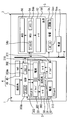
図1は、第一実施形態による操舵アシスト制御システムを示すブロック図であり、
図2は、第一実施形態によるEPS装置及び舵取り装置を示す構成図であり、
図3は、第一実施形態による操舵アシスト制御システムを搭載した自車両の車室内を示す内観図であり、
図4は、第一実施形態による視覚提示状態を示す正面図であり、
図5は、第一実施形態による視覚提示状態を示す正面図であり、
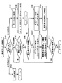
図6は、第一実施形態による操舵アシスト制御フローを示すフローチャートであり、
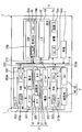
図7は、第二実施形態による操舵アシスト制御システムを示すブロック図であり、
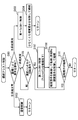
図8は、第三実施形態による操舵アシスト制御フローを示すフローチャートであり、
図9は、図1の変形例を示すブロック図であり、
図10は、図1の変形例を示すブロック図である。
The above and other objects, features and advantages of the present disclosure will become more apparent from the following detailed description with reference to the accompanying drawings. In the accompanying drawings,
FIG. 1 is a block diagram showing a steering assist control system according to the first embodiment. FIG. 2 is a configuration diagram showing the EPS device and the steering device according to the first embodiment. FIG. 3 is an interior view showing the interior of the host vehicle equipped with the steering assist control system according to the first embodiment. FIG. 4 is a front view showing a visual presentation state according to the first embodiment. FIG. 5 is a front view showing a visual presentation state according to the first embodiment. FIG. 6 is a flowchart showing a steering assist control flow according to the first embodiment. FIG. 7 is a block diagram showing a steering assist control system according to the second embodiment. FIG. 8 is a flowchart showing a steering assist control flow according to the third embodiment. FIG. 9 is a block diagram showing a modification of FIG. FIG. 10 is a block diagram showing a modification of FIG.
以下、本開示の複数の実施形態を図面に基づいて説明する。尚、各実施形態において対応する構成要素には同一の符号を付すことにより、重複する説明を省略する場合がある。各実施形態において構成の一部分のみを説明している場合、当該構成の他の部分については、先行して説明した他の実施形態の構成を適用することができる。また、各実施形態の説明において明示している構成の組み合わせばかりではなく、特に組み合わせに支障が生じなければ、明示していなくても複数の実施形態の構成同士を部分的に組み合せることができる。
Hereinafter, a plurality of embodiments of the present disclosure will be described with reference to the drawings. In addition, the overlapping description may be abbreviate | omitted by attaching | subjecting the same code | symbol to the corresponding component in each embodiment. When only a part of the configuration is described in each embodiment, the configuration of the other embodiment described above can be applied to the other part of the configuration. In addition, not only combinations of configurations explicitly described in the description of each embodiment, but also the configurations of a plurality of embodiments can be partially combined even if they are not explicitly specified unless there is a problem with the combination. .
(第一実施形態)
図1に示すように、本開示が適用される第一実施形態の操舵アシスト制御システム1は、自車両2に搭載された電動パワーステアリング(EPS)装置3及び情報提示装置5から、構成されている。これら操舵アシスト制御システム1の各装置3,5は、LAN(Local Area Network)等の車内ネットワーク6を介して互いに接続されている。ここで車内ネットワーク6には、車速センサ7が接続されている。この車速センサ7は、自車両2の車速を検知することで、当該検知に応じた車速信号を出力する。また、車内ネットワーク6には、車速以外の車両情報や、ナビゲーション情報、標識情報、障害物情報等を出力する電装品も、接続されている。 (First embodiment)
As shown in FIG. 1, the steeringassist control system 1 according to the first embodiment to which the present disclosure is applied includes an electric power steering (EPS) device 3 and an information presentation device 5 mounted on a host vehicle 2. Yes. The devices 3 and 5 of the steering assist control system 1 are connected to each other via an in-vehicle network 6 such as a LAN (Local Area Network). Here, a vehicle speed sensor 7 is connected to the in-vehicle network 6. The vehicle speed sensor 7 detects a vehicle speed of the host vehicle 2 and outputs a vehicle speed signal corresponding to the detection. The in-vehicle network 6 is also connected to electrical components that output vehicle information other than the vehicle speed, navigation information, sign information, obstacle information, and the like.
図1に示すように、本開示が適用される第一実施形態の操舵アシスト制御システム1は、自車両2に搭載された電動パワーステアリング(EPS)装置3及び情報提示装置5から、構成されている。これら操舵アシスト制御システム1の各装置3,5は、LAN(Local Area Network)等の車内ネットワーク6を介して互いに接続されている。ここで車内ネットワーク6には、車速センサ7が接続されている。この車速センサ7は、自車両2の車速を検知することで、当該検知に応じた車速信号を出力する。また、車内ネットワーク6には、車速以外の車両情報や、ナビゲーション情報、標識情報、障害物情報等を出力する電装品も、接続されている。 (First embodiment)
As shown in FIG. 1, the steering
(装置構成)
以下、各装置3,5の構成を詳細に説明する。 (Device configuration)
Hereinafter, the structure of each apparatus 3 and 5 is demonstrated in detail.
以下、各装置3,5の構成を詳細に説明する。 (Device configuration)
Hereinafter, the structure of each
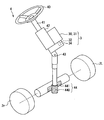
図1,2に示すようにEPS装置3は、自車両2の舵取り装置4に付設されている。ここで舵取り装置4は、操舵ハンドル40、操舵シャフト41、コラム42、ユニバーサルジョイント43、ギアボックス44、トルクセンサ45及び操舵角センサ46を備えている。
As shown in FIGS. 1 and 2, the EPS device 3 is attached to the steering device 4 of the host vehicle 2. The steering device 4 includes a steering handle 40, a steering shaft 41, a column 42, a universal joint 43, a gear box 44, a torque sensor 45, and a steering angle sensor 46.
図2,3に示すように操舵ハンドル40は、自車両2の車室2c内において運転席20よりも前方に設置され、当該運転席20上のユーザにより回転操作可能となっている。図2に示す操舵シャフト41は、操舵ハンドル40の回転操作により印加された操舵トルクを受けて、当該操舵ハンドル40と一体に回転する。コラム42は、操舵シャフト41のうち車室2c内部分を内包するハウジングである。ユニバーサルジョイント43は、操舵トルクを操舵シャフト41から受けて出力端まで伝達する。
2 and 3, the steering handle 40 is installed in front of the driver's seat 20 in the passenger compartment 2c of the host vehicle 2 and can be rotated by a user on the driver's seat 20. The steering shaft 41 shown in FIG. 2 receives the steering torque applied by the rotation operation of the steering handle 40 and rotates integrally with the steering handle 40. The column 42 is a housing that encloses a portion of the steering shaft 41 in the passenger compartment 2c. The universal joint 43 receives steering torque from the steering shaft 41 and transmits it to the output end.
ギアボックス44は、ユニバーサルジョイント43の出力端に設けられたピニオンギア440を、ラック軸441に噛合させることで構成されている。ギアボックス44は、ピニオンギア440の回転運動をラック軸441の直線運動に変換する。ラック軸441の両端は、タイロッド等を介して自車両2の左右の操舵輪2r,2lにそれぞれ連結されている。以上の構成により舵取り装置4では、操舵ハンドル40が左側へ回転操作されるのに応じて操舵輪2r,2lが左側へ操舵される一方、操舵ハンドル40が右側へ回転操作されるのに応じて操舵輪2r,2lが右側へ操舵される。
The gear box 44 is configured by meshing a pinion gear 440 provided at the output end of the universal joint 43 with the rack shaft 441. The gear box 44 converts the rotational motion of the pinion gear 440 into linear motion of the rack shaft 441. Both ends of the rack shaft 441 are connected to the left and right steering wheels 2r and 2l of the host vehicle 2 via tie rods or the like. With the configuration described above, in the steering device 4, the steering wheels 2r and 2l are steered to the left as the steering handle 40 is rotated to the left, while the steering handle 40 is rotated to the right. The steered wheels 2r and 2l are steered to the right.
図1に示すトルクセンサ45及び操舵角センサ46は、コラム42(図2参照)に設置されることで、いずれも車内ネットワーク6に接続されている。トルクセンサ45は、操舵ハンドル40の回転操作により操舵シャフト41に印加された操舵トルクを検知することで、当該検知に応じたトルク信号を出力する。操舵角センサ46は、回転操作による操舵ハンドル40の操舵角(即ち、切れ角)を検知することで、当該検知に応じた操舵角信号を出力する。ここで操舵角とは、例えば図3に示すθiのように、自車両2の直進方向に対応する零点θ0を基準として、左右のそれぞれに操舵ハンドル40が回転する回転角をいう。
The torque sensor 45 and the steering angle sensor 46 shown in FIG. 1 are both connected to the in-vehicle network 6 by being installed in the column 42 (see FIG. 2). The torque sensor 45 detects a steering torque applied to the steering shaft 41 by rotating the steering handle 40, and outputs a torque signal corresponding to the detection. The steering angle sensor 46 detects a steering angle (that is, a turning angle) of the steering handle 40 by a rotation operation, and outputs a steering angle signal corresponding to the detection. Here, the steering angle refers to a rotation angle at which the steering handle 40 rotates to the left and right with reference to the zero point θ0 corresponding to the straight traveling direction of the host vehicle 2, for example, θi shown in FIG.
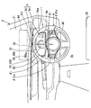
図1,2に示すようにEPS装置3は、複数系統として二系統のアクチュエータユニット30,31を備えていると共に、出力シャフト32、回転角センサ33及び減速機構34をそれら二系統に共通に備えている。ここでEPS装置3は、本実施形態ではコラム42(図2参照)に設置されるコラム式であるが、ラック軸441の周囲に設置されるラック式等であってもよい。
As shown in FIGS. 1 and 2, the EPS apparatus 3 includes two systems of actuator units 30 and 31 as a plurality of systems, and includes an output shaft 32, a rotation angle sensor 33, and a speed reduction mechanism 34 in common to the two systems. ing. Here, the EPS device 3 is a column type installed in the column 42 (see FIG. 2) in this embodiment, but may be a rack type installed around the rack shaft 441 or the like.
図1に示すように各系統のアクチュエータユニット30,31は、電動モータ300,310、駆動ドライバ301,311、電流センサ302,312及びアシストECU(Electronic Control Unit)303,313を個別に有している。
As shown in FIG. 1, the actuator units 30 and 31 of each system individually have electric motors 300 and 310, drive drivers 301 and 311, current sensors 302 and 312 and assist ECUs (Electronic Control Units) 303 and 313. Yes.
各系統の電動モータ300,310は、三相ブラシレスモータ等から構成され、通電により出力トルクを発生する。各系統の電動モータ300,310は、それぞれの出力トルクを共通の出力シャフト32に対して与える。そこで本実施形態では、全系統の電動モータ300,310に関して出力トルクを合成した合成トルクを、アシストトルクTaと定義する。両系統に共通の回転角センサ33は、かかるアシストトルクTaを受けて回転する出力シャフト32の出力回転角を検知することで、当該検知に応じた回転角信号を出力する。
The electric motors 300 and 310 of each system are composed of a three-phase brushless motor or the like, and generate output torque when energized. The electric motors 300 and 310 of each system give respective output torques to the common output shaft 32. Therefore, in the present embodiment, the combined torque obtained by combining the output torques for the electric motors 300 and 310 of all systems is defined as the assist torque Ta. The rotation angle sensor 33 common to both systems detects the output rotation angle of the output shaft 32 that rotates in response to the assist torque Ta, and outputs a rotation angle signal corresponding to the detection.
各系統の駆動ドライバ301,311は、三相インバータ回路等から構成され、同一系統の電動モータ300,310を個別に通電駆動する。各系統の電流センサ302,312は、同一系統に関して駆動ドライバ301,311による電動モータ300,310への通電電流を検知することで、当該検知に応じた電流信号を個別に出力する。各系統のアシストECU303,313は、それぞれプロセッサ303p,313p及びメモリ303m,313mを個別に有するマイクロコンピュータを主体として、構成されている。各系統のアシストECU303,313は、同一系統の駆動ドライバ301,311及び電流センサ302,312と、車内ネットワーク6及びセンサ33,45,46とに接続されている。各系統のアシストECU303,313は、同一系統の駆動ドライバ301,311に対してそれぞれ駆動指令信号を出力することで、同一系統の電動モータ300,310に対する通電駆動を制御する。このとき各系統のアシストECU303,313は、それぞれの制御状態を状態信号の相互出力により監視し合うことで、アシストトルクTaを協働して制御する。また、このとき各系統のアシストECU303,313は、車速信号の表す車速と、回転角信号の表す出力回転角と、トルク信号の表す操舵トルクと、操舵角信号の表す操舵角等に基づき、アシストトルクTaを制御する。
The drive drivers 301 and 311 of each system are constituted by a three-phase inverter circuit or the like, and individually energize and drive the electric motors 300 and 310 of the same system. The current sensors 302 and 312 of each system individually output current signals corresponding to the detection by detecting energization currents to the electric motors 300 and 310 by the drive drivers 301 and 311 for the same system. The assist ECUs 303 and 313 of each system are mainly configured by a microcomputer having processors 303p and 313p and memories 303m and 313m, respectively. The assist ECUs 303 and 313 of each system are connected to the drive drivers 301 and 311 and current sensors 302 and 312 of the same system, and the in-vehicle network 6 and the sensors 33, 45, and 46. The assist ECUs 303 and 313 in each system control the energization drive for the electric motors 300 and 310 in the same system by outputting drive command signals to the drive drivers 301 and 311 in the same system, respectively. At this time, the assist ECUs 303 and 313 of each system cooperatively control the assist torque Ta by monitoring each control state by mutual output of state signals. At this time, the assist ECUs 303 and 313 of each system assist based on the vehicle speed represented by the vehicle speed signal, the output rotation angle represented by the rotation angle signal, the steering torque represented by the torque signal, the steering angle represented by the steering angle signal, and the like. Torque Ta is controlled.
図2に示す減速機構34は、複数のギアを組み合わせて構成され、操舵シャフト41及び出力シャフト32の間に介装されている。減速機構34は、出力シャフト32のアシストトルクTaを増幅して、操舵シャフト41に伝達する。これによりアシストトルクTaは、操舵ハンドル40の回転操作に応じた操舵輪2r,2lの操舵を補助することとなる。
2 is configured by combining a plurality of gears, and is interposed between the steering shaft 41 and the output shaft 32. The speed reduction mechanism 34 amplifies the assist torque Ta of the output shaft 32 and transmits it to the steering shaft 41. As a result, the assist torque Ta assists the steering of the steered wheels 2r and 2l according to the rotation operation of the steering handle 40.
図1,3に示すように情報提示装置5は、自車両2の車室2c内において運転席20上のユーザに各種情報を提示するために、音響系5s及び表示系5dを組み合わせて構成されている。
As shown in FIGS. 1 and 3, the information presentation device 5 is configured by combining an acoustic system 5 s and a display system 5 d in order to present various types of information to the user on the driver's seat 20 in the passenger compartment 2 c of the host vehicle 2. ing.
音響系5sは、操舵ハンドル40の周囲のうち、操舵ハンドル40よりも前方のインストルメントパネル22に設置されている。音響系5sは、フルレンジスピーカ5ssに音源回路5scを組み合わせて構成され、当該音源回路5scにより車内ネットワーク6と接続されている。音響系5sは、運転席20上のユーザにより知覚可能な可聴域の警告音Swを操舵ハンドル40の周囲のフルレンジスピーカ5ssから発することで、当該警告音Swを聴覚提示する。ここで警告音Swは、EPS装置3の異常を警告する音波の他、ナビゲーション情報及び障害物情報を報知又は警告する音波等であってもよい。
The acoustic system 5 s is installed in the instrument panel 22 ahead of the steering handle 40 in the periphery of the steering handle 40. The acoustic system 5s is configured by combining a full-range speaker 5ss with a sound source circuit 5sc, and is connected to the in-vehicle network 6 by the sound source circuit 5sc. The acoustic system 5s generates an audible warning sound Sw perceivable by the user on the driver's seat 20 from the full range speaker 5ss around the steering handle 40, thereby presenting the warning sound Sw in an auditory manner. Here, the warning sound Sw may be a sound wave for notifying or warning navigation information and obstacle information, in addition to a sound wave for warning the abnormality of the EPS device 3.
表示系5dは、HUD50、コンビネーションメータ52及びHCU54を備えている。HCUはHMI(Human Machine Interface) Control Unitを表す。HUD50およびコンビネーションメータ52は表示要素とも呼ぶ。
The display system 5d includes a HUD 50, a combination meter 52, and an HCU 54. HCU represents HMI (Human Machine Interface) Control Unit. The HUD 50 and the combination meter 52 are also called display elements.
ヘッドアップディスプレイ(HUD)50は、操舵ハンドル40よりも前方のインストルメントパネル22に設置されている。HUD50は、液晶パネル又はプロジェクタ等により形成した表示画像56を、自車両2のフロントウインドシールド21のうち表示領域Adに対して投影する。このとき、フロントウインドシールド21で反射した表示画像56の光束と、フロントウインドシールド21を透過した外界風景からの光束とが、運転席20上のユーザにより知覚される。その結果、フロントウインドシールド21よりも前方に結像される表示画像56の虚像が外界風景の一部に重畳することで、それら表示画像56の虚像と外界風景の実像とが運転席20上のユーザに視覚提示される。
The head-up display (HUD) 50 is installed on the instrument panel 22 in front of the steering handle 40. The HUD 50 projects a display image 56 formed by a liquid crystal panel, a projector, or the like onto the display area Ad in the front windshield 21 of the host vehicle 2. At this time, the luminous flux of the display image 56 reflected by the front windshield 21 and the luminous flux from the outside scene transmitted through the front windshield 21 are perceived by the user on the driver's seat 20. As a result, the virtual image of the display image 56 formed in front of the front windshield 21 is superimposed on a part of the external scene, so that the virtual image of the display image 56 and the real image of the external scene are displayed on the driver seat 20. Visually presented to the user.
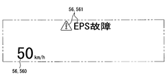
ここで表示画像56は、図3,4に示す如く車速を報知する報知表示画像560や、図4に示す如くEPS装置3の異常を警告する警告表示画像561の他、ナビゲーション情報、標識情報及び障害物情報を報知する画像等であってもよい。また、インストルメントパネル22に設置されてフロントウインドシールド21と共同して外界風景を透過させる透光性コンバイナを用いることで、当該コンバイナに表示画像56を投影して虚像表示を実現してもよい。
Here, the display image 56 includes a notification display image 560 for notifying the vehicle speed as shown in FIGS. 3 and 4, a warning display image 561 for warning the abnormality of the EPS device 3 as shown in FIG. The image etc. which alert | report obstacle information may be sufficient. Further, by using a translucent combiner that is installed on the instrument panel 22 and transmits the outside scenery in cooperation with the front windshield 21, a display image 56 may be projected onto the combiner to realize a virtual image display. .
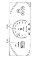
図3に示すようにコンビネーションメータ52は、操舵ハンドル40よりも前方のインストルメントパネル22に設置されている。コンビネーションメータ52は、液晶パネル等により表示画像57を形成することで、当該表示画像57の実像を運転席20上のユーザに視覚提示する。ここで表示画像57は、図3,5に示す如く車速を報知する報知表示画像570や、図5に示す如くEPS装置3の異常を警告する警告表示画像571の他、ナビゲーション情報、標識情報及び障害物情報を報知する画像等であってもよい。
As shown in FIG. 3, the combination meter 52 is installed on the instrument panel 22 in front of the steering handle 40. The combination meter 52 visually displays the real image of the display image 57 to the user on the driver's seat 20 by forming the display image 57 using a liquid crystal panel or the like. The display image 57 includes a notification display image 570 for notifying the vehicle speed as shown in FIGS. 3 and 5 and a warning display image 571 for warning the abnormality of the EPS device 3 as shown in FIG. The image etc. which alert | report obstacle information may be sufficient.
図1に示すようにHCU54は、プロセッサ54p及びメモリ54mを有するマイクロコンピュータを主体として、構成されている。HCU54は、車内ネットワーク6と、表示系5dにおける表示要素50,52とに接続されている。HCU54は、音響系5sの作動と、表示系5dにおける表示要素50,52の作動とを制御する。ここで、特に本実施形態のHCU54は、アシストECU303,313から出力される提示指令信号に基づき、音響系5sによる警告音Swの聴覚提示と、表示要素50,52による警告表示画像561,571の視覚提示とを制御する。
As shown in FIG. 1, the HCU 54 is mainly composed of a microcomputer having a processor 54p and a memory 54m. The HCU 54 is connected to the in-vehicle network 6 and the display elements 50 and 52 in the display system 5d. The HCU 54 controls the operation of the acoustic system 5s and the operations of the display elements 50 and 52 in the display system 5d. Here, in particular, the HCU 54 of this embodiment, based on the presentation command signals output from the assist ECUs 303 and 313, provides auditory presentation of the warning sound Sw by the acoustic system 5 s and warning display images 561 and 571 by the display elements 50 and 52. Control visual presentation.
(操舵アシスト制御フロー)
次に、図6に示す操舵アシスト制御フローにつき、詳細に説明する。 (Steering assist control flow)
Next, the steering assist control flow shown in FIG. 6 will be described in detail.
次に、図6に示す操舵アシスト制御フローにつき、詳細に説明する。 (Steering assist control flow)
Next, the steering assist control flow shown in FIG. 6 will be described in detail.
アシストECU303,313及びHCU54は、メモリ303m,313m,54mに個別に記憶の制御プログラムをそれぞれプロセッサ303p,313p,54pにより実行することで、「操舵アシスト制御方法」としての操舵アシスト制御フローを協働して実現する。尚、自車両2において操舵アシスト制御フローは、ユーザによるパワースイッチのオン操作に応じて開始され、同スイッチのオフ操作に応じて終了する。また、操舵アシスト制御フロー中の「S」とは、各ステップを意味する。さらにまた、操舵アシスト制御フローを実現するための制御プログラムを記憶するメモリ303m,313m,54mは、半導体メモリ、磁気媒体若しくは光学媒体等といった記憶媒体を、一つ又は複数使用してそれぞれ構成される。
The assist ECUs 303 and 313 and the HCU 54 cooperate with the steering assist control flow as a “steering assist control method” by executing the control programs stored in the memories 303m, 313m, and 54m individually by the processors 303p, 313p, and 54p, respectively. And realized. Note that the steering assist control flow in the host vehicle 2 is started in response to a power switch ON operation by the user, and is ended in response to the switch OFF operation. “S” in the steering assist control flow means each step. Furthermore, the memories 303m, 313m, and 54m that store a control program for realizing the steering assist control flow are respectively configured by using one or a plurality of storage media such as a semiconductor memory, a magnetic medium, or an optical medium. .
操舵アシスト制御フローのS101では、アシストECU303,313の協働により、各系統のアクチュエータユニット30,31を監視して、それらユニット30,31の少なくとも一系統に異常を検知したか否かを判定する。ここで、片側一系統のアクチュエータユニット30における異常とは、当該片側一系統の電動モータ300、駆動ドライバ301及びアシストECU303等のうち、少なくとも一要素に発生した異常である。また、別側一系統のアクチュエータユニット31における異常とは、当該別側一系統の電動モータ310、駆動ドライバ311及びアシストECU313等のうち、少なくとも一要素に発生した異常である。こうした異常検知は、いずれの系統にあっても、電流信号の表す通電電流や、回転角信号の表す出力回転角、状態信号の表す制御状態等に基づくことで、実現可能である。
In S101 of the steering assist control flow, by cooperation of the assist ECUs 303 and 313, the actuator units 30 and 31 of each system are monitored to determine whether or not an abnormality has been detected in at least one system of the units 30 and 31. . Here, the abnormality in the one-sided one-line actuator unit 30 is an abnormality that has occurred in at least one element of the one-sided one-line electric motor 300, the drive driver 301, the assist ECU 303, and the like. Further, the abnormality in the actuator unit 31 of the other side system is an abnormality that has occurred in at least one element among the electric motor 310, the drive driver 311, the assist ECU 313, and the like of the other side system. Such abnormality detection can be realized in any system based on an energization current represented by a current signal, an output rotation angle represented by a rotation angle signal, a control state represented by a state signal, and the like.
S101では、いずれの系統のアクチュエータユニット30,31も正常であるとの判定を下すと、S102へ移行する。こうした全系統正常時のS102では、アシストトルクTaに関する通常制御を、アシストECU303,313の協働により実行する。具体的に通電制御では、電動モータ300,310のうち自車両2の運転状況に応じた少なくとも一方を通電駆動することで、当該運転状況に適したアシストトルクTaを出力する。以上の後、S101へと戻る。
In S101, if it is determined that the actuator units 30 and 31 of any system are normal, the process proceeds to S102. In S102 when all the systems are normal, normal control related to the assist torque Ta is executed by the cooperation of the assist ECUs 303 and 313. Specifically, in the energization control, at least one of the electric motors 300 and 310 according to the driving situation of the host vehicle 2 is energized to output the assist torque Ta suitable for the driving situation. After the above, the process returns to S101.
一方でS101では、全系統のアクチュエータユニット30,31に異常が生じているとの判定を下すと、S103へ移行する。こうした全系統異常時のS103では、アシストトルクTaに関する第一フェイルセーフ制御を、アシストECU303,313の協働により実行する。具体的に第一フェイルセーフ制御では、電動モータ300,310のうち、自車両2の運転状況及び全系統異常の内容に応じた少なくとも一方を通電駆動することで、安全性を確保する上で必要最小限のアシストトルクTaを出力する。
On the other hand, if it is determined in S101 that an abnormality has occurred in the actuator units 30 and 31 of all systems, the process proceeds to S103. In S103 when all the systems are abnormal, the first failsafe control related to the assist torque Ta is executed by the cooperation of the assist ECUs 303 and 313. Specifically, in the first fail-safe control, it is necessary to ensure safety by energizing and driving at least one of the electric motors 300 and 310 according to the operation status of the host vehicle 2 and the contents of the abnormality of the entire system. The minimum assist torque Ta is output.
このようなS103の実行に伴って移行するS104では、音響系5sによる警告音Swの聴覚提示と、表示要素50,52による警告表示画像561,571の視覚提示とのうち、少なくとも視覚提示をHCU54により制御する。このとき、HCU54による制御に従った少なくとも視覚提示は、全系統異常が解消されるまで継続される。
In S104, which is shifted in accordance with the execution of S103, at least visual presentation is performed between the auditory presentation of the warning sound Sw by the acoustic system 5s and the visual presentation of the warning display images 561 and 571 by the display elements 50 and 52. Control by. At this time, at least visual presentation according to the control by the HCU 54 is continued until all system abnormalities are resolved.
また一方でS101では、アクチュエータユニット30,31のうち、特定一系統には異常が生じ且つ残系統は正常であるとの判定を下すと、S105へ移行する。こうした一系統異常時のS105では、操舵ハンドル40が回転操作されているか否かを、アシストECU303,313の協働により判定する。具体的には、操舵信号の表す操舵角と、トルク信号の表す操舵トルクとに基づくことで、操舵ハンドル40が左右のいずれかに回転操作されているか否かを判定する。
On the other hand, if it is determined in S101 that an abnormality has occurred in one specific system among the actuator units 30 and 31, and the remaining system is normal, the process proceeds to S105. In S105 at the time of such one system abnormality, it is determined by the cooperation of the assist ECUs 303 and 313 whether or not the steering handle 40 is being rotated. Specifically, based on the steering angle represented by the steering signal and the steering torque represented by the torque signal, it is determined whether or not the steering handle 40 has been rotated to the left or right.
S105では、回転操作なしとの否定判定を下す間は、同S105を繰り返して実行する。これに対し、S105にて回転操作ありとの肯定判定を下すと、S106へ移行する。S106では、零点θ0に対する左右いずれかへの操舵角が所定の間欠点θiまで進角したか否かを、アシストECU303,313の協働により判定する。具体的に間欠点θiは、図3の如く零点θ0から左右のそれぞれへと設定角度δθsずつ進角した操舵角毎に、複数設定される。設定角度δθsは、所定角度とも呼びうる。そこでS106での判定は、操舵信号の表す操舵角と、トルク信号の表す操舵トルクとに基づくことで、零点θ0又は先に到達の間欠点θiから設定角度δθs以上、操舵ハンドル40の回転操作が進行したか否かによって行われる。ここで設定角度δθsは、ユーザによる一系統異常の認識性と、ユーザの感じる煩わしさとの兼ね合い等を考慮して、例えば5度程度の角度幅に設定される。尚、図3では、零点θ0を挟んで左右両側に設定される一対の間欠点θiのみが代表的に示されており、他の間欠点θiについては図示が省略されている。
In S105, S105 is repeatedly executed while making a negative determination that there is no rotation operation. On the other hand, if it affirmation determinates that there exists rotation operation in S105, it will transfer to S106. In S106, it is determined by the cooperation of the assist ECUs 303 and 313 whether or not the steering angle to the left or right with respect to the zero point θ0 has advanced to the defect θi for a predetermined time. Specifically, a plurality of inter-defects θi are set for each steering angle advanced by a set angle δθs from the zero point θ0 to the left and right as shown in FIG. The set angle δθs can also be called a predetermined angle. Therefore, the determination in S106 is based on the steering angle represented by the steering signal and the steering torque represented by the torque signal, so that the rotation operation of the steering handle 40 is performed at the set angle δθs or more from the zero point θ0 or the defect θi while reaching first. It is done depending on whether it has progressed. Here, the set angle δθs is set to, for example, an angle width of about 5 degrees in consideration of the balance between the user's recognition of one-system abnormality and the annoyance felt by the user. In FIG. 3, only a pair of inter-defects θi set on both the left and right sides of the zero point θ0 is representatively shown, and the other inter-defects θi are not shown.
S106では、零点θ0又は先の間欠点θiから次の間欠点θiまで操舵角が進角したとの肯定判定を下すと、S107へ移行する。S107では、アシストトルクTaに関して、特に操舵ハンドル40の回転操作に伴う第二フェイルセーフ制御を、アシストECU303,313の協働により実行する。具体的に第二フェイルセーフ制御では、電動モータ300,310のうち自車両2の運転状況及び一系統異常の内容に応じた少なくとも一方を通電駆動することで、一系統異常前となるS102での通常制御時よりもアシストトルクTaを低下させて出力する。
In S106, if an affirmative determination is made that the steering angle has advanced from the zero point θ0 or the previous intermediate defect θi to the next intermediate defect θi, the process proceeds to S107. In S107, regarding the assist torque Ta, the second fail-safe control associated with the rotation operation of the steering handle 40 is executed by the cooperation of the assist ECUs 303 and 313. Specifically, in the second fail-safe control, at least one of the electric motors 300 and 310 according to the operation status of the host vehicle 2 and the content of the one-system abnormality is energized and driven, so that in S102 before the one-system abnormality occurs. The assist torque Ta is reduced and output as compared with the normal control.
このようなS107の実行に伴って移行するS108では、音響系5sによる警告音Swの聴覚提示と、表示要素50,52による警告表示画像561,571の視覚提示とを、HCU54により制御する。このとき聴覚提示及び視覚提示は、HCU54による制御に従って、後述するS111での判定終了まで継続される。
In S108, which is shifted along with the execution of S107, the HCU 54 controls the auditory presentation of the warning sound Sw by the acoustic system 5s and the visual presentation of the warning display images 561 and 571 by the display elements 50 and 52. At this time, the auditory presentation and the visual presentation are continued until the determination in S111 to be described later is completed according to the control by the HCU 54.
一方でS106では、零点θ0又は先の間欠点θiから次の間欠点θiまでは操舵角が進角していないとの否定判定を下すと、S109へ移行する。S109では、アシストトルクTaに関して、特に操舵ハンドル40の回転操作に伴う第三フェイルセーフ制御を、アシストECU303,313の協働により実行する。具体的に第三フェイルセーフ制御では、電動モータ300,310のうち自車両2の運転状況及び一系統異常の内容に応じた少なくとも一方を通電駆動することで、S107での第二フェイルセーフ制御時よりもアシストトルクTaを高めて出力する。このとき、電動モータ300,310のうち正常な一系統のみを自車両2の高速走行中に通電駆動する場合等には、一系統異常前となるS102での通常制御時と実質同一であることで第二フェイルセーフ制御時よりも高いトルクに、アシストトルクTaを制御する。これに対し、両系統の電動モータ300,310を自車両2の走行停止中に通電駆動する場合等には、一系統異常前となる通常制御時よりも低く且つ第二フェイルセーフ制御時よりも高いトルクに、アシストトルクTaを制御する。
On the other hand, in S106, if a negative determination is made that the steering angle has not advanced from the zero point θ0 or the previous shortcoming θi to the next shortcoming θi, the flow proceeds to S109. In S109, with respect to the assist torque Ta, the third fail-safe control associated with the rotation operation of the steering handle 40 is executed in cooperation with the assist ECUs 303 and 313. Specifically, in the third fail-safe control, at least one of the electric motors 300 and 310 according to the operation status of the host vehicle 2 and the content of the one-system abnormality is energized to drive the second fail-safe control in S107. The assist torque Ta is increased and output. At this time, when only one normal system of the electric motors 300 and 310 is energized and driven while the host vehicle 2 is traveling at high speed, it is substantially the same as in the normal control in S102 before one system abnormality occurs. Thus, the assist torque Ta is controlled to a torque higher than that in the second fail-safe control. On the other hand, when the electric motors 300 and 310 of both systems are energized and driven while the host vehicle 2 is stopped, it is lower than the normal control time before the one-system abnormality and than the second fail-safe control time. The assist torque Ta is controlled to a high torque.
このようなS109の実行に伴って移行するS110では、表示要素50,52による警告表示画像561,571の視覚提示を、HCU54により制御する。このとき視覚提示は、HCU54による制御に従って、S111での判定終了まで継続される。
In S110 that shifts with the execution of S109, the visual display of the warning display images 561 and 571 by the display elements 50 and 52 is controlled by the HCU 54. At this time, the visual presentation is continued until the determination in S <b> 111 ends according to the control by the HCU 54.
S108,S110の実行終了後にはいずれも、S111へと移行する。S111では、操舵ハンドル40の回転操作が継続されているか否かを、アシストECU303,313の協働により判定する。具体的には、操舵信号の表す操舵角と、トルク信号の表す操舵トルクとに基づくことで、操舵ハンドル40に対して左右いずれかへの回転操作が継続されているか否かにより判定する。
After the completion of execution of S108 and S110, the process proceeds to S111. In S111, it is determined by the cooperation of the assist ECUs 303 and 313 whether or not the rotation operation of the steering handle 40 is continued. Specifically, based on the steering angle represented by the steering signal and the steering torque represented by the torque signal, the determination is made based on whether or not the steering operation on the steering handle 40 is continued to the left or right.
S111では、回転操作が継続中との肯定判定を下すと、S106へ戻る一方、回転操作の終了に応じて否定判定を下すと、S101へ戻る。故に、以上の如くしてS105~S111が実行される一系統異常時には、操舵ハンドル40の回転操作が設定角度δθsずつ進行する毎に、アシストトルクTaが一系統異常前の通常制御時よりも繰り返し低下させられると共に、警告音Swが間欠的に発せられる。このとき、特に本実施形態のアシストトルクTaは、S107により設定角度δθ毎に一旦低下してから、S109により通常制御時に対しては実質同一又は低くなる当該低下前のトルクへと戻されるようになっている。
In S111, if an affirmative determination is made that the rotation operation is continuing, the process returns to S106, whereas if a negative determination is made in accordance with the end of the rotation operation, the process returns to S101. Therefore, at the time of one system abnormality in which S105 to S111 are executed as described above, the assist torque Ta is repeated more than the normal control before the one system abnormality every time the rotation operation of the steering handle 40 proceeds by the set angle δθs. While being lowered, the warning sound Sw is intermittently emitted. At this time, in particular, the assist torque Ta of the present embodiment is once reduced for each set angle δθ by S107 and then returned to the pre-decrease torque that is substantially the same or lower than that for normal control by S109. It has become.
尚、ここまで説明の第一実施形態では、「監視ステップ」としてのS101を実行するアシストECU303,313が、「監視部」に相当する。また、第一実施形態では、「トルク制御ステップ」としてのS105~S107,S109,S111を実行するアシストECU303,313が、「トルク制御部」に相当する。さらにまた、第一実施形態では、「警告制御ステップ」としてのS108,S110を実行するHCU54が、「警告制御部」に相当する。
In the first embodiment described so far, the assist ECUs 303 and 313 that execute S101 as the “monitoring step” correspond to the “monitoring unit”. In the first embodiment, the assist ECUs 303 and 313 that execute S105 to S107, S109, and S111 as “torque control steps” correspond to “torque control units”. Furthermore, in the first embodiment, the HCU 54 that executes S108 and S110 as the “warning control step” corresponds to the “warning control unit”.
(効果)
以上説明した第一実施形態の効果の一例を、以下に説明する。 (effect)
An example of the effect of the first embodiment described above will be described below.
以上説明した第一実施形態の効果の一例を、以下に説明する。 (effect)
An example of the effect of the first embodiment described above will be described below.
第一実施形態によると、アクチュエータユニット30,31のうち特定一系統に異常が生じ且つ残系統は正常な一系統異常時には、それらの全系統に関して出力トルクを合成したアシストトルクTaが制御される。このとき、操舵ハンドル40の回転操作に伴ってアシストトルクTaが一系統異常前よりも低く制御されるのに伴って、情報提示装置5の音響系5sが制御されて警告音Swが聴覚提示される。これよれば、自車両2内のユーザは、操舵ハンドル40から受ける操作反力の増大によってだけでなく、当該提示の警告音Swによっても、一系統異常を認識することができる。故に、低く制御されたアシストトルクTaによって操舵の補助機能を維持しつつも、操舵ハンドル40の回転操作の度に一系統異常をユーザへと気付かせ得る。したがって、複数系統のアクチュエータユニット30,31を利用してフェイルセーフ性を高めることと、ユーザによる一系統異常の認識性を高めることとにつき、両立させることが可能となる。
According to the first embodiment, when an abnormality occurs in one specific system among the actuator units 30 and 31, and the remaining system is normal, the assist torque Ta obtained by synthesizing the output torque is controlled with respect to all the systems. At this time, as the assist torque Ta is controlled to be lower than that before the one-system abnormality in accordance with the rotation operation of the steering handle 40, the acoustic system 5s of the information presentation device 5 is controlled and the warning sound Sw is presented auditorily. The According to this, the user in the host vehicle 2 can recognize the one-system abnormality not only by the increase in the reaction force received from the steering handle 40 but also by the presented warning sound Sw. Therefore, one system abnormality can be noticed to the user each time the steering handle 40 is rotated while the assist function of steering is maintained by the assist torque Ta controlled to be low. Therefore, it is possible to achieve both of improving the fail-safe property by using the actuator units 30 and 31 of a plurality of systems and enhancing the recognizability of one-system abnormality by the user.
また、第一実施形態の一系統異常時には、操舵ハンドル40の回転操作が設定角度δθsずつ進行する毎に、アシストトルクTaが一系統異常前よりも低下する。これによれば、回転操作の設定角度δθs毎に操舵ハンドル40からの操作反力が繰り返し増大することで、ユーザは、一系統異常を気付き易くなる。即ち、ユーザによる一系統異常の認識性が高められ得る。
In addition, when the one-system abnormality of the first embodiment is performed, the assist torque Ta is decreased more than before the one-system abnormality every time the rotation operation of the steering handle 40 proceeds by the set angle δθs. According to this, the operation reaction force from the steering handle 40 is repeatedly increased at each rotation operation setting angle δθs, so that the user can easily notice one-system abnormality. That is, it is possible to improve the recognizability of the one-system abnormality by the user.
さらに、第一実施形態の一系統異常時には、操舵ハンドル40の回転操作が設定角度δθsずつ進行する毎に、アシストトルクTaが一旦低下してから当該低下前のトルクまで戻ることとなる。これによれば、アシストトルクTaの低下量を必要最小限に留めて、安全性を確保しつつ、回転操作の設定角度δθs毎に操舵ハンドル40からの操作反力を繰り返し増大させて、ユーザによる一系統異常の認識性を高め得る。
Further, when one system abnormality occurs in the first embodiment, every time the rotation operation of the steering handle 40 proceeds by the set angle δθs, the assist torque Ta once decreases and then returns to the torque before the decrease. According to this, the operation reaction force from the steering handle 40 is repeatedly increased at each rotation operation setting angle δθs while the safety torque is kept low while the amount of decrease in the assist torque Ta is kept to the minimum, and the user can The recognition ability of one system abnormality can be improved.
またさらに、第一実施形態の一系統異常時には、操舵ハンドル40の回転操作が設定角度δθsずつ進行する毎に、警告音Swが間欠的に発せられる。これによれば、操舵ハンドル40からの操作反力が繰り返し増大する回転操作の設定角度δθs毎に、ユーザは、当該増大と共に警告音Swも間欠的に繰り返し受けることで、一系統異常を確実に認識し得る。即ち、ユーザによる一系統異常の認識性を高める効果につき、確実性が増す。
Furthermore, a warning sound Sw is intermittently generated every time the rotation operation of the steering handle 40 advances by the set angle δθs when the one system abnormality of the first embodiment is performed. According to this, for every set angle δθs of the rotational operation in which the operation reaction force from the steering handle 40 repeatedly increases, the user receives the warning sound Sw intermittently repeatedly along with the increase, so that one-system abnormality can be ensured. It can be recognized. That is, the certainty increases with respect to the effect of improving the recognizability of the one-system abnormality by the user.
加えて、第一実施形態の一系統異常時に情報提示装置5の音響系5sは、自車両2内のうち操舵ハンドル40の周囲から警告音Swを発するので、その警告対象が当該操舵ハンドル40に関連する一系統異常であることを、ユーザに認識させ易くなる。即ち、ユーザによる一系統異常の認識性が高められ得る。
In addition, the acoustic system 5s of the information presentation apparatus 5 emits a warning sound Sw from around the steering handle 40 in the host vehicle 2 when the one-system abnormality occurs in the first embodiment. It becomes easy for a user to recognize that it is a related one-system abnormality. That is, it is possible to improve the recognizability of the one-system abnormality by the user.
また加えて、第一実施形態の一系統異常時には、アシストトルクTaが低く制御されるのに伴って、自車両2内のユーザには、警告音Swの聴覚提示と共に警告表示画像561,571の視覚提示も実行されることになる。これによりユーザは、操舵ハンドル40からの操作反力の増大によるだけでなく、提示された警告音Sw及び警告表示画像561,571によることで、一系統異常を認識し易くなる。即ち、ユーザによる一系統異常の認識性が高められ得る。
In addition, when the one-system abnormality is in the first embodiment, the assist torque Ta is controlled to be low, and the warning display images 561 and 571 are displayed to the user in the host vehicle 2 together with the auditory presentation of the warning sound Sw. Visual presentation will also be performed. Thus, the user can easily recognize the one-system abnormality not only due to the increase in the reaction force from the steering wheel 40 but also due to the presented warning sound Sw and the warning display images 561 and 571. That is, it is possible to improve the recognizability of the one-system abnormality by the user.
(第二実施形態)
図7に示すように本開示の第二実施形態は、第一実施形態の変形例である。第二実施形態による情報提示装置2005の音響系2005sは、自車両2の車室2c内に複数点在するパラメトリックスピーカ2005ssに音源回路5scを組み合わせて構成され、当該音源回路5cにより車内ネットワーク6と接続されている。音響系2005sは、複数のパラメトリックスピーカ2005ssから超音波Suを発することで、ユーザにより知覚可能な可聴域の警告音Swを運転席20上に出現させて聴覚提示する。即ち、音響系2005sは、運転席20へと向かう指向性を警告音Swに与えることとなる。 (Second embodiment)
As shown in FIG. 7, the second embodiment of the present disclosure is a modification of the first embodiment. Theacoustic system 2005s of the information presentation device 2005 according to the second embodiment is configured by combining a sound source circuit 5sc with a plurality of parametric speakers 2005ss located in the passenger compartment 2c of the host vehicle 2, and the sound source circuit 5c and the in-vehicle network 6 are combined. It is connected. The acoustic system 2005 s emits an ultrasonic wave Su from a plurality of parametric speakers 2005 ss to cause an audible warning sound Sw that can be perceived by the user to appear on the driver's seat 20 for auditory presentation. That is, the acoustic system 2005 s gives the warning sound Sw directivity toward the driver seat 20.
図7に示すように本開示の第二実施形態は、第一実施形態の変形例である。第二実施形態による情報提示装置2005の音響系2005sは、自車両2の車室2c内に複数点在するパラメトリックスピーカ2005ssに音源回路5scを組み合わせて構成され、当該音源回路5cにより車内ネットワーク6と接続されている。音響系2005sは、複数のパラメトリックスピーカ2005ssから超音波Suを発することで、ユーザにより知覚可能な可聴域の警告音Swを運転席20上に出現させて聴覚提示する。即ち、音響系2005sは、運転席20へと向かう指向性を警告音Swに与えることとなる。 (Second embodiment)
As shown in FIG. 7, the second embodiment of the present disclosure is a modification of the first embodiment. The
このような第二実施形態においてHCU54は、音響系2005sの作動を、表示系5dにおける表示要素50,52の作動と共に制御する。故に第二実施形態では、第一実施形態の操舵アシスト制御フローにおいて音響系5sを音響系2005sと読み替えて、S104,S108を実行する。これにより、ハンドル周囲からの警告音Swによる効果を除いて、第一実施形態と同様の効果が発揮される。さらに、第二実施形態の一系統異常時に情報提示装置2005の音響系2005sは、自車両2内のうち運転席20へと向かう指向性を警告音Swに与えるので、当該運転席20上のユーザに一系統異常を確実に認識させ得る。即ち、ユーザによる一系統異常の認識性を高める効果につき、確実性が増す。
In such a second embodiment, the HCU 54 controls the operation of the acoustic system 2005s together with the operation of the display elements 50 and 52 in the display system 5d. Therefore, in the second embodiment, the acoustic system 5s is replaced with the acoustic system 2005s in the steering assist control flow of the first embodiment, and S104 and S108 are executed. As a result, the same effects as those of the first embodiment are exhibited except for the effects of the warning sound Sw from around the steering wheel. Furthermore, since the acoustic system 2005s of the information presentation apparatus 2005 gives the directivity toward the driver's seat 20 in the own vehicle 2 to the warning sound Sw when the one-system abnormality is in the second embodiment, the user on the driver's seat 20 It is possible to reliably recognize one system abnormality. That is, the certainty increases with respect to the effect of improving the recognizability of the one-system abnormality by the user.
(第三実施形態)
図8に示すように本開示の第三実施形態は、第一実施形態の変形例である。第三実施形態の操舵アシスト制御フローでは、S106,S109,S110を実行せず、またS108に代わるS3108を実行する。 (Third embodiment)
As shown in FIG. 8, the third embodiment of the present disclosure is a modification of the first embodiment. In the steering assist control flow of the third embodiment, S106, S109, and S110 are not executed, and S3108 is executed instead of S108.
こうした操舵アシスト制御フローでは、S105にて回転操作ありとの肯定判定を下すと、S107へと直接に移行することで、同S107の実行に伴ってS3108へもさらに移行する。具体的にS3108では、HCU54による制御に従って、表示要素50,52による警告表示画像561,571の視覚提示をS111での判定終了まで継続する。一方でS3108では、HCU54による制御に従って、音響系5sによる警告音Swの聴覚提示をS111での判定終了まで断続させる。このとき、警告音Swを断続的に発生させる断続周期Pwについては、S105にて肯定判定が下されてからの時間経過に従って、漸次短縮させる。
In such a steering assist control flow, if an affirmative determination is made that there is a rotation operation in S105, the process proceeds directly to S107, and further proceeds to S3108 as S107 is executed. Specifically, in S3108, according to the control by the HCU 54, the visual display of the warning display images 561 and 571 by the display elements 50 and 52 is continued until the determination in S111 is completed. On the other hand, in S3108, according to the control by the HCU 54, the auditory presentation of the warning sound Sw by the acoustic system 5s is interrupted until the determination in S111 ends. At this time, the intermittent cycle Pw for intermittently generating the warning sound Sw is gradually shortened as time elapses after the positive determination is made in S105.
このようなS3108の実行終了には、S111へと移行する。その結果としてS111では、回転操作が継続中との肯定判定を下すと、S107へ戻る一方、回転操作の終了に応じて否定判定を下すと、S101へ戻る。故に、以上の如くS105,S107,S3108,S111が実行される一系統異常時には、操舵ハンドル40の回転操作が進行する間に亘って、アシストトルクTaが一系統異常前の通常制御時よりも継続低下することとなる。それと共に、一系統異常時において操舵ハンドル40の回転操作が進行する間は、時間経過に従って短縮される断続周期Pwにて、警告音Swが断続的に発せられることとなる。
At the end of execution of S3108, the process proceeds to S111. As a result, in S111, if a positive determination is made that the rotation operation is continuing, the process returns to S107, whereas if a negative determination is made in response to the end of the rotation operation, the process returns to S101. Therefore, at the time of one system abnormality in which S105, S107, S3108, and S111 are executed as described above, the assist torque Ta is continued from the normal control before the one system abnormality during the rotation operation of the steering handle 40. Will be reduced. At the same time, while the rotation operation of the steering wheel 40 proceeds in the event of an abnormality in one system, the warning sound Sw is intermittently emitted at the intermittent period Pw that is shortened with time.
尚、ここまで説明の第一実施形態では、「トルク制御ステップ」としてのS105,S107,S111を実行するアシストECU303,313が、「トルク制御部」に相当する。また、第一実施形態では、「警告制御ステップ」としてのS3108を実行するHCU54が、「警告制御部」に相当する。
In the first embodiment described so far, the assist ECUs 303 and 313 that execute S105, S107, and S111 as “torque control steps” correspond to “torque control units”. In the first embodiment, the HCU 54 that executes S3108 as the “warning control step” corresponds to the “warning control unit”.
以上より、第三実施形態の一系統異常時には、操舵ハンドル40の回転操作が進行する間に亘って、アシストトルクTaが一系統異常前よりも低下する。これによれば、回転操作の間は操舵ハンドル40からの操作反力が増大し続けることで、ユーザは、一系統異常を気付き易くなる。即ち、ユーザによる一系統異常の認識性が高められ得る。
As described above, when the one-system abnormality is in the third embodiment, the assist torque Ta is lower than that before the one-system abnormality as the rotation operation of the steering handle 40 proceeds. According to this, the operation reaction force from the steering handle 40 continues to increase during the rotation operation, so that the user can easily notice a one-system abnormality. That is, it is possible to improve the recognizability of the one-system abnormality by the user.
また、第三実施形態の一系統異常時には、操舵ハンドル40の回転操作が進行する間、警告音Swが断続的に発せられる。これによれば、操舵ハンドル40からの操作反力が増大し続ける回転操作の間、警告音Swは断続させてユーザの感じる煩わしさを軽減しつつも、当該ユーザによる一系統異常の認識性を高め得る。ここで特に、警告音Swを断続させる断続周期Pwが時間経過に従って短縮されることによれば、ユーザは、一系統異常の重大さを直感的に認識し易くなるのである。
Further, when the one-system abnormality of the third embodiment occurs, the warning sound Sw is intermittently emitted while the rotation operation of the steering handle 40 proceeds. According to this, during the rotation operation in which the operation reaction force from the steering handle 40 continues to increase, the warning sound Sw is interrupted to reduce the annoyance felt by the user, but the user can recognize the one-system abnormality. Can increase. Here, in particular, when the intermittent period Pw for interrupting the warning sound Sw is shortened over time, the user can easily intuitively recognize the seriousness of the one-system abnormality.
(他の実施形態)
ここまで本開示の複数の実施形態について説明したが、本開示は、それらの実施形態に限定して解釈されるものではなく、本開示の要旨を逸脱しない範囲内において種々の実施形態及び組み合わせに適用することができる。 (Other embodiments)
Although a plurality of embodiments of the present disclosure have been described so far, the present disclosure is not construed as being limited to those embodiments, and various embodiments and combinations can be made without departing from the scope of the present disclosure. Can be applied.
具体的に、第一及び第二実施形態に関する変形例1の操舵アシスト制御フローでは、S109においてアシストトルクTaを、同S109の実行前と同一トルクに制御してもよい。これにより、変形例1の一系統異常時には、操舵ハンドル40の回転操作が設定角度δθsずつ進行する毎に、当該異常前の通常制御時に対してアシストトルクTaの低下量が漸次増大することとなる。
Specifically, in the steering assist control flow of the first modification relating to the first and second embodiments, the assist torque Ta may be controlled to the same torque as before the execution of S109 in S109. As a result, when an abnormality occurs in the one system of the modification 1, every time the rotation operation of the steering handle 40 proceeds by the set angle δθs, the amount of decrease in the assist torque Ta gradually increases with respect to the normal control before the abnormality. .
第一及び第二実施形態に関する変形例2の操舵アシスト制御フローでは、S110において音響系5sによる警告音Swの聴覚提示を制御して、S111での判定終了まで継続させてもよい。これにより、変形例2の一系統異常時には、操舵ハンドル40の回転操作が進行する間に亘って、警告音Swが継続的に発せられることとなる。
In the steering assist control flow of the second modification regarding the first and second embodiments, the auditory presentation of the warning sound Sw by the acoustic system 5s may be controlled in S110 and continued until the determination in S111 ends. As a result, when one system abnormality occurs in the second modification, the warning sound Sw is continuously generated while the rotation operation of the steering handle 40 proceeds.
第三実施形態に関する変形例3の操舵アシスト制御フローでは、S3108において音響系5sにより警告音Swを断続的に発生させる断続周期Pwを、一定周期に設定してもよい。またそれに代えて、第三実施形態に関する変形例4の操舵アシスト制御フローでは、S3108において音響系5sにより警告音Swを断続的に発生させる断続周期Pwを、時間経過に従って増大させてもよい。
In the steering assist control flow of the third modification related to the third embodiment, the intermittent cycle Pw in which the warning sound Sw is intermittently generated by the acoustic system 5s in S3108 may be set to a constant cycle. Alternatively, in the steering assist control flow of the fourth modification regarding the third embodiment, the intermittent period Pw in which the warning sound Sw is intermittently generated by the acoustic system 5s in S3108 may be increased as time elapses.
第三実施形態に関する変形例5の操舵アシスト制御フローでは、S3108において音響系5sによる警告音Swの聴覚提示を制御して、S111での判定終了まで継続させてもよい。これにより、変形例5の一系統異常時には、操舵ハンドル40の回転操作が進行する間に亘って、警告音Swが継続的に発せられることとなる。
In the steering assist control flow of the fifth modification related to the third embodiment, the auditory presentation of the warning sound Sw by the acoustic system 5s may be controlled in S3108 and continued until the determination in S111 ends. Thereby, when the one system abnormality of the modified example 5 occurs, the warning sound Sw is continuously emitted while the rotation operation of the steering handle 40 proceeds.
第一~第三実施形態に関する変形例6の操舵アシスト制御フローでは、表示要素50,52による警告表示画像561,571のうち少なくとも一方の視覚提示を、S108,S110,S3108において実行しなくてもよい。またそれに代えて、あるいはそれに加えて、第一~第三実施形態に関する変形例7の操舵アシスト制御フローでは、自車両2の車室2c内において表示要素50,52以外に設けられた表示部による警告表示の視覚提示を、S108,S110,S3108において実行してもよい。
In the steering assist control flow of the sixth modification regarding the first to third embodiments, visual presentation of at least one of the warning display images 561 and 571 by the display elements 50 and 52 is not executed in S108, S110, and S3108. Good. In addition, in addition to or in addition, in the steering assist control flow of the modified example 7 relating to the first to third embodiments, the display unit provided in addition to the display elements 50 and 52 in the passenger compartment 2c of the host vehicle 2 is used. Visual presentation of a warning display may be performed in S108, S110, and S3108.
第一及び第二実施形態に関する変形例8の操舵アシスト制御フローでは、表示要素50,52による警告表示画像561,571の視覚提示を、S108,S110の少なくとも一方において実行しなくてもよい。また同様に、第三実施形態に関する変形例9の操舵アシスト制御フローでは、表示要素50,52による警告表示画像561,571の視覚提示を、S3108において実行しなくてもよい。
In the steering assist control flow of the modified example 8 regarding the first and second embodiments, visual presentation of the warning display images 561 and 571 by the display elements 50 and 52 may not be executed in at least one of S108 and S110. Similarly, in the steering assist control flow of the modification 9 relating to the third embodiment, visual presentation of the warning display images 561 and 571 by the display elements 50 and 52 may not be executed in S3108.
第一及び第三実施形態に関する変形例10では、自車両2の車室2c内のうち操舵ハンドル40の周囲以外の箇所に、音響系5sを設置してもよい。またそれに代えて、第三実施形態に関する変形例11では、音響系5sに変えて、第二実施形態に準ずる音響系2005sを採用してもよい。
In the tenth modification related to the first and third embodiments, the acoustic system 5s may be installed in a portion other than the periphery of the steering handle 40 in the passenger compartment 2c of the host vehicle 2. Alternatively, in the modification 11 related to the third embodiment, an acoustic system 2005s according to the second embodiment may be adopted instead of the acoustic system 5s.
第一~第三実施形態に関する変形例12では、各系統の電動モータ300,310に個別に出力シャフト32を設けて、それら各出力シャフト32を個別の減速機構34により操舵シャフト41と連結させてもよい。またそれに代えて、あるいはそれに加えて、第一~第三実施形態に関する変形例13では、図9(同図は第一実施形態の変形例13)に示すように、EPS装置3にて各系統のアクチュエータユニット30,31に共通となる構成要素として、アシストECU303のみを設けてもよい。これにより変形例13では、各系統の電動モータ300,310に対する通電駆動を共通のアシストECU303により制御することで、S102,S103,S107,S109でのアシストトルクTaの制御を当該アシストECU303により実行してもよい。
In the twelfth modification related to the first to third embodiments, the output shafts 32 are individually provided in the electric motors 300 and 310 of each system, and the output shafts 32 are connected to the steering shaft 41 by the individual reduction mechanisms 34. Also good. In place of or in addition to that, in the modified example 13 related to the first to third embodiments, each system is used in the EPS apparatus 3 as shown in FIG. 9 (the modified example is the modified example 13 of the first embodiment). Only the assist ECU 303 may be provided as a component common to the actuator units 30 and 31. Thereby, in the modified example 13, the assist torque Ta in S102, S103, S107, and S109 is controlled by the assist ECU 303 by controlling the energization drive for the electric motors 300 and 310 of each system by the common assist ECU 303. May be.
第一~第三実施形態に関する変形例14では、図10(同図は第一実施形態の変形例14)に示すように、HCU54を設けなくてもよい。このような変形例14では、例えば表示要素50,52に設けられる表示ECUのうち一方が有するプロセッサにより、当該一方のメモリに記憶の制御プログラムを実行することで、操舵アシスト制御フローの一部を実現してもよい。尚、図10は、HUD50のうちプロセッサ54p及びメモリ54mを有したECU50eにより「警告制御部」を構築する場合の変形例14を、示している。ECU50eは表示ECUとも呼びうる。
In the modification 14 related to the first to third embodiments, the HCU 54 may not be provided as shown in FIG. 10 (the modification is the modification 14 of the first embodiment). In the modified example 14 described above, for example, one of the display ECUs provided in the display elements 50 and 52 executes a control program stored in the one memory by a processor included in one of the display ECUs. It may be realized. FIG. 10 shows a modification 14 in the case where the “warning control unit” is constructed by the ECU 50e having the processor 54p and the memory 54m in the HUD 50. The ECU 50e can also be called a display ECU.
第一~第三実施形態に関する変形例15では、二系統のアクチュエータユニット30,31に加えて、さらに少なくとも一系統のアクチュエータユニットをEPS装置3に設けてもよい。
In Modification 15 regarding the first to third embodiments, in addition to the two systems of actuator units 30 and 31, at least one system of actuator units may be provided in the EPS device 3.
なお、本出願に記載されるフローチャート、あるいは、フローチャートの処理は、複数のステップ(あるいはセクションとも言及される)から構成され、各ステップは、たとえば、S101と表現される。さらに、各ステップは、複数のサブステップに分割されることができる、一方、複数のステップが合わさって一つのステップにすることも可能である。
It should be noted that the flowchart described in the present application or the process of the flowchart is composed of a plurality of steps (also referred to as sections), and each step is expressed as, for example, S101. Further, each step can be divided into a plurality of sub-steps, while a plurality of steps can be combined into one step.
以上、本開示による操舵アシスト制御システム、操舵アシスト制御方法の実施形態および構成を例示したが、本開示に係る実施の形態および構成は、上述した各実施の形態および各構成に限定されるものではない。異なる実施の形態および構成にそれぞれ開示された技術的要素を適宜組み合わせて得られる実施の形態および構成についても本開示に係る実施の形態および構成の範囲に含まれる。
As described above, the embodiments and configurations of the steering assist control system and the steering assist control method according to the present disclosure have been illustrated, but the embodiments and configurations according to the present disclosure are not limited to the above-described embodiments and configurations. Absent. Embodiments and configurations obtained by appropriately combining technical elements disclosed in different embodiments and configurations are also included in the scope of the embodiments and configurations according to the present disclosure.
Claims (11)
- 情報提示装置(5,2005)を搭載した自車両(2)において、操舵ハンドル(40)の回転操作に応じた操舵を補助するアシストトルク(Ta)を、複数系統のアクチュエータユニット(30,31)により制御する操舵アシスト制御システム(1)であって、
各系統の前記アクチュエータユニットを監視する監視部(S101)と、
特定一系統の前記アクチュエータユニットには異常が生じ且つ残系統の前記アクチュエータユニットは正常であるとの判定が前記監視部により下された一系統異常時に、全系統の前記アクチュエータユニットに関して出力トルクを合成した前記アシストトルクを、前記操舵ハンドルの前記回転操作に伴って前記一系統異常前よりも低く制御するトルク制御部(S105~S107,S109,S111)と、
前記アシストトルクが前記トルク制御部により低く制御されるのに伴って、前記自車両内に警告音(Sw)を聴覚提示するように、前記情報提示装置を制御する警告制御部(S108,S110,S3108)とを、備える操舵アシスト制御システム。 In the host vehicle (2) equipped with the information presentation device (5, 2005), the assist torque (Ta) for assisting the steering according to the rotation operation of the steering handle (40) is supplied to the actuator units (30, 31) of a plurality of systems. A steering assist control system (1) controlled by
A monitoring unit (S101) for monitoring the actuator unit of each system;
When an abnormality occurs in the actuator unit of a specific system and the determination that the actuator unit of the remaining system is normal is made by the monitoring unit, output torque is synthesized for the actuator units of all systems A torque control unit (S105 to S107, S109, S111) that controls the assist torque that is lower than before the one-system abnormality in accordance with the rotation operation of the steering handle;
As the assist torque is controlled to be lower by the torque control unit, a warning control unit (S108, S110, S3108), a steering assist control system. - 前記トルク制御部は、前記一系統異常時において前記回転操作が設定角度(δθs)ずつ進行する毎に、前記アシストトルクを前記一系統異常前よりも低下させる請求項1に記載の操舵アシスト制御システム。 2. The steering assist control system according to claim 1, wherein the torque control unit decreases the assist torque more than before the one system abnormality every time the rotation operation proceeds by a set angle (δθs) when the one system abnormality occurs. .
- 前記トルク制御部は、前記一系統異常時において前記回転操作が前記設定角度ずつ進行する毎に、前記アシストトルクを一旦低下させてから当該低下前のトルクに戻す請求項2に記載の操舵アシスト制御システム。 3. The steering assist control according to claim 2, wherein the torque control unit temporarily reduces the assist torque and returns the torque to the torque before the decrease every time the rotation operation proceeds by the set angle when the one system is abnormal. system.
- 前記警告制御部は、前記一系統異常時において前記回転操作が前記設定角度ずつ進行する毎に、前記警告音を間欠的に発する請求項2又は3に記載の操舵アシスト制御システム。 4. The steering assist control system according to claim 2, wherein the warning control unit intermittently emits the warning sound every time the rotation operation proceeds by the set angle when the one system is abnormal.
- 前記トルク制御部は、前記一系統異常時において前記回転操作が進行する間に亘って、前記アシストトルクを前記一系統異常前よりも低下させる請求項1に記載の操舵アシスト制御システム。 2. The steering assist control system according to claim 1, wherein the torque control unit lowers the assist torque as compared to before the one-system abnormality while the rotation operation proceeds when the one-system abnormality occurs.
- 前記警告制御部は、前記一系統異常時において前記回転操作が進行する間、前記警告音を断続的に発する請求項5に記載の操舵アシスト制御システム。 6. The steering assist control system according to claim 5, wherein the warning control unit intermittently emits the warning sound while the rotation operation proceeds when the one system is abnormal.
- 前記警告制御部は、前記警告音を断続させる断続周期(Pw)を、時間経過に従って短縮させる請求項6に記載の操舵アシスト制御システム。 The steering assist control system according to claim 6, wherein the warning control unit shortens an intermittent cycle (Pw) for intermittently transmitting the warning sound as time elapses.
- 前記警告制御部は、前記自車両内のうち前記操舵ハンドルの周囲から前記警告音を発する前記情報提示装置(5)を、制御する請求項1~7のいずれか一項に記載の操舵アシスト制御システム。 The steering assist control according to any one of claims 1 to 7, wherein the warning control unit controls the information presentation device (5) that emits the warning sound from around the steering wheel in the host vehicle. system.
- 前記警告制御部は、前記自車両内のうち運転席(20)へ向かう指向性を前記警告音に与える前記情報提示装置(2005)を、制御する請求項1~7のいずれか一項に記載の操舵アシスト制御システム。 The warning control unit controls the information presentation device (2005) that gives the warning sound directivity toward the driver's seat (20) in the host vehicle. Steering assist control system.
- 前記警告制御部は、前記アシストトルクが前記トルク制御部により低く制御されるのに伴って、前記自車両内に警告表示(561,571)を視覚提示するように、前記情報提示装置を制御する請求項1~9のいずれか一項に記載の操舵アシスト制御システム。 The warning control unit controls the information presenting device to visually present a warning display (561, 571) in the host vehicle as the assist torque is controlled to be lower by the torque control unit. The steering assist control system according to any one of claims 1 to 9.
- 情報提示装置(5,2005)を搭載した自車両(2)において、操舵ハンドル(40)の回転操作に応じた操舵を補助するアシストトルク(Ta)を、複数系統のアクチュエータユニット(30,31)により制御する操舵アシスト制御方法であって、
各系統の前記アクチュエータユニットを監視する監視ステップ(S101)と、
特定一系統の前記アクチュエータユニットには異常が生じ且つ残系統の前記アクチュエータユニットは正常であるとの判定が前記監視ステップにより下された一系統異常時に、全系統の前記アクチュエータユニットに関して出力トルクを合成した前記アシストトルクを、前記回転操作に伴って前記一系統異常前よりも低く制御するトルク制御ステップ(S105~S107,S109,S111)と、
前記アシストトルクが前記トルク制御ステップにより低く制御されるのに伴って、前記自車両内に警告音(Sw)を聴覚提示するように、前記情報提示装置を制御する警告制御ステップ(S108,S110,S3108)とを、含む操舵アシスト制御方法。 In the host vehicle (2) equipped with the information presentation device (5, 2005), the assist torque (Ta) for assisting the steering according to the rotation operation of the steering handle (40) is supplied to the actuator units (30, 31) of a plurality of systems. A steering assist control method controlled by
A monitoring step (S101) for monitoring the actuator unit of each system;
When an abnormality occurs in the actuator unit of a specific system and the determination that the actuator unit of the remaining system is normal is made by the monitoring step, the output torque is synthesized for the actuator units of all systems A torque control step (S105 to S107, S109, S111) for controlling the assist torque to be lower than that before the one-system abnormality in accordance with the rotation operation;
As the assist torque is controlled to be lower by the torque control step, a warning control step (S108, S110, S110, S110, S110, S110, S110, S110, S110, S110, S110, S110, S110, S110, S110) S3108).
Priority Applications (1)
| Application Number | Priority Date | Filing Date | Title |
|---|---|---|---|
| US15/562,599 US10377412B2 (en) | 2015-04-03 | 2016-03-24 | Steering assist control system and steering assist control method |
Applications Claiming Priority (2)
| Application Number | Priority Date | Filing Date | Title |
|---|---|---|---|
| JP2015077086A JP6327190B2 (en) | 2015-04-03 | 2015-04-03 | Steering assist control system and steering assist control method |
| JP2015-077086 | 2015-04-03 |
Publications (1)
| Publication Number | Publication Date |
|---|---|
| WO2016157851A1 true WO2016157851A1 (en) | 2016-10-06 |
Family
ID=57004099
Family Applications (1)
| Application Number | Title | Priority Date | Filing Date |
|---|---|---|---|
| PCT/JP2016/001715 WO2016157851A1 (en) | 2015-04-03 | 2016-03-24 | Steering assistance control system and steering assistance control method |
Country Status (3)
| Country | Link |
|---|---|
| US (1) | US10377412B2 (en) |
| JP (1) | JP6327190B2 (en) |
| WO (1) | WO2016157851A1 (en) |
Cited By (2)
| Publication number | Priority date | Publication date | Assignee | Title |
|---|---|---|---|---|
| CN109050397A (en) * | 2018-07-27 | 2018-12-21 | 吉利汽车研究院(宁波)有限公司 | A kind of driver slips out of the hand the device and method of warning |
| CN109533007A (en) * | 2017-09-21 | 2019-03-29 | 操纵技术Ip控股公司 | Wire-controlled steering system diagnosis |
Citations (4)
| Publication number | Priority date | Publication date | Assignee | Title |
|---|---|---|---|---|
| JPH11134581A (en) * | 1997-10-28 | 1999-05-21 | Matsushita Electric Works Ltd | Warning device |
| JP2000099835A (en) * | 1998-09-25 | 2000-04-07 | Matsushita Electric Works Ltd | Burglar prevention sensor |
| JP2013251936A (en) * | 2012-05-30 | 2013-12-12 | Denso Corp | Motor drive device and electrically-driven power steering device including the same |
| JP2014010773A (en) * | 2012-07-02 | 2014-01-20 | Denso Corp | Display device for vehicle |
Family Cites Families (9)
| Publication number | Priority date | Publication date | Assignee | Title |
|---|---|---|---|---|
| JP3839358B2 (en) | 2002-06-12 | 2006-11-01 | 株式会社ジェイテクト | Vehicle steering control device and vehicle steering control method |
| JP2007210365A (en) | 2006-02-07 | 2007-08-23 | Toyota Motor Corp | Power steering control device |
| JP2008211910A (en) * | 2007-02-26 | 2008-09-11 | Jtekt Corp | Motor control device and electric power steering device |
| JP5233178B2 (en) * | 2007-06-14 | 2013-07-10 | 株式会社ジェイテクト | Motor control device and electric power steering device |
| JP4900167B2 (en) | 2007-09-27 | 2012-03-21 | 株式会社デンソー | Vehicle steering system |
| CN102781763B (en) * | 2011-02-21 | 2014-09-03 | 丰田自动车株式会社 | Electric power steering device |
| JP5896202B2 (en) | 2011-10-20 | 2016-03-30 | 株式会社ジェイテクト | Electric power steering device |
| JP6586930B2 (en) * | 2016-08-04 | 2019-10-09 | トヨタ自動車株式会社 | Vehicle travel control device |
| JP6489080B2 (en) * | 2016-08-04 | 2019-03-27 | トヨタ自動車株式会社 | Vehicle control device |
-
2015
- 2015-04-03 JP JP2015077086A patent/JP6327190B2/en not_active Expired - Fee Related
-
2016
- 2016-03-24 WO PCT/JP2016/001715 patent/WO2016157851A1/en active Application Filing
- 2016-03-24 US US15/562,599 patent/US10377412B2/en active Active
Patent Citations (4)
| Publication number | Priority date | Publication date | Assignee | Title |
|---|---|---|---|---|
| JPH11134581A (en) * | 1997-10-28 | 1999-05-21 | Matsushita Electric Works Ltd | Warning device |
| JP2000099835A (en) * | 1998-09-25 | 2000-04-07 | Matsushita Electric Works Ltd | Burglar prevention sensor |
| JP2013251936A (en) * | 2012-05-30 | 2013-12-12 | Denso Corp | Motor drive device and electrically-driven power steering device including the same |
| JP2014010773A (en) * | 2012-07-02 | 2014-01-20 | Denso Corp | Display device for vehicle |
Cited By (2)
| Publication number | Priority date | Publication date | Assignee | Title |
|---|---|---|---|---|
| CN109533007A (en) * | 2017-09-21 | 2019-03-29 | 操纵技术Ip控股公司 | Wire-controlled steering system diagnosis |
| CN109050397A (en) * | 2018-07-27 | 2018-12-21 | 吉利汽车研究院(宁波)有限公司 | A kind of driver slips out of the hand the device and method of warning |
Also Published As
| Publication number | Publication date |
|---|---|
| JP6327190B2 (en) | 2018-05-23 |
| US20180086367A1 (en) | 2018-03-29 |
| JP2016196247A (en) | 2016-11-24 |
| US10377412B2 (en) | 2019-08-13 |
Similar Documents
| Publication | Publication Date | Title |
|---|---|---|
| JP5324648B2 (en) | Vehicle control device | |
| JP3675459B2 (en) | Stabilizer control device | |
| JP5804198B2 (en) | Vehicle steering control apparatus and steering control method | |
| JP2575522Y2 (en) | Power steering device | |
| JP2005346372A (en) | Driving operation auxiliary device for vehicle and vehicle having it | |
| JP5673748B2 (en) | Vehicle control device | |
| JP6011304B2 (en) | Lane maintenance support device | |
| WO2016157851A1 (en) | Steering assistance control system and steering assistance control method | |
| JP4007200B2 (en) | Electric power steering device | |
| JP5943138B2 (en) | Collision avoidance support device and collision avoidance support method | |
| JP2012144111A (en) | Steer-by-wire system | |
| JP4014817B2 (en) | Vehicle steering control device | |
| JP2009179185A (en) | Diagnostic device and method of steer-by-wire system | |
| JP5293136B2 (en) | Vehicle steering system | |
| JP2003267249A (en) | Steering device for vehicle | |
| JP2011251640A (en) | Vehicle steering device | |
| KR101551659B1 (en) | Method and Apparatus for Generating Vibration by Using MDPS Motor | |
| JP2016196247A5 (en) | ||
| JP7312074B2 (en) | Rudder angle control device | |
| CN108216352B (en) | Vehicle auxiliary steering system with vibration function and control method thereof | |
| JP4283198B2 (en) | Vehicle steering control device | |
| JP2008265613A (en) | Electric power steering device | |
| TWI610835B (en) | Vehicle auxiliary steering system with vibration function and control method thereof | |
| JP2005053304A (en) | Electric power steering device | |
| JP2007039032A (en) | Electric power steering device |
Legal Events
| Date | Code | Title | Description |
|---|---|---|---|
| 121 | Ep: the epo has been informed by wipo that ep was designated in this application |
Ref document number: 16771741 Country of ref document: EP Kind code of ref document: A1 |
|
| WWE | Wipo information: entry into national phase |
Ref document number: 15562599 Country of ref document: US |
|
| NENP | Non-entry into the national phase |
Ref country code: DE |
|
| 122 | Ep: pct application non-entry in european phase |
Ref document number: 16771741 Country of ref document: EP Kind code of ref document: A1 |